Embed Size (px)
Citation preview

ARTICLE IN PRESS
Optimum X-plate dampers for seismic response controlof piping systems
S.V. Bakrea, R.S. Jangida,�, G.R. Reddyb
aDepartment of Civil Engineering, Indian Institute of Technology Bombay, Powai, Mumbai 400 076, IndiabReactor Safety Division, Bhabha Atomic Research Center, Anushaktinagar, Mumbai 400 058, India
Abstract
In a vibrating system, the most effective mechanism to dissipate energy is the inelastic strain of supplemental metallic elements with
plastic deforming characteristics. An X-plate damper (XPD) is one device that is capable of sustaining many cycles of stable yielding
deformation resulting in a high level of energy dissipation or damping. The present paper focuses on a numerical study to investigate the
seismic effectiveness of an XPD for piping systems in industrial units (e.g. chemical and petrochemical industries) and utilities such as
thermal and nuclear power plants. The seismic performance of piping systems is investigated under important parametric variations of
the damper properties (i.e. height, width and thickness of the XPD) under arbitrary ground motions. Investigations are reported for an
industrial piping system equipped with an XPD and the response quantities of interest are the relative displacements, absolute
accelerations and support reactions of the piping system. The response quantities of the controlled (with XPD) piping system are
compared with the corresponding uncontrolled (without XPD) piping systems, to establish the seismic effectiveness of the XPD. Seismic
energy dissipation in the piping system, which is represented by the hysteretic energy of the XPD, is also evaluated and compared. It is
observed that the XPDs are very effective in reducing the seismic response of piping systems. Moreover, for a given piping system and
ground motion, it is difficult to arrive at the optimum properties of an XPD from the parametric variation of the properties of the XPD
and by monitoring the responses of the piping system. Therefore, use of hysteretic energy dissipation by an XPD is proposed to obtain
the optimum properties of the XPD. Furthermore, the effects of the properties of an XPD on the free vibration characteristics of the
piping system are also presented, which is crucial for the design of piping systems with XPDs.
Keywords: Piping system; X-plate damper; Hysteretic; Seismic; Energy; Parametric; Optimum parameters
1. Introduction
Structural control using energy dissipating devices is anappealing alternative to the traditional earthquake-resis-tant design approaches. In this approach, a substantialportion of the vibration energy is absorbed or consumed atselected locations within a structure through protectivedevices especially designed for this purpose. In particular,passive control devices offer various advantages overfunctionally complex active and semi-active control de-vices. Devices in this class have the ability to dissipate theearthquake input energy by virtue of their nonlinear
behavior. Since these protective devices are separated fromthe main structure, they act as structural ‘fuses’ that can bereplaced, if damaged, after the occurrence of a severeseismic event. For piping systems, these devices shouldsatisfy the basic requirement of thermal expansion withoutgeneration of undesired stresses. During strong earth-quakes, it should be ensured that these devices dissipatemost of the earthquake input energy and thereby reducethe forces transferred to the piping system. At present,snubbers are used in nuclear power plants to reduce theseismic forces in the piping system. However, snubbers arevery expensive and are associated with problems of oilleakage (in the case of hydraulic snubbers) and locking (inthe case of mechanical snubbers) and as a result, requirefrequent inspection. Hence, Olson and Tang [1] and Cloud

Nomenclature
a post-to-pre-yield stiffness ratiob Wen’s model parameterg Wen’s model parametert Wen’s model parametersy yield stress of an XPDa half the height of an XPDb width of an XPDn Wen’s model parametert thickness of an XPDA Wen’s model parameter
E modulus of elasticityEd percentage energy dissipated by an XPDEh hysteretic energy in an XPDEI input energy to the piping systemF force in an XPDFy yield force of an XPDH rate of hardeningKd initial stiffness of an XPDq yield displacement of an XPDxp displacement of piping system€xp absolute acceleration of piping system_xp relative velocity of piping system
673
et al. [2] proposed the reduced use of snubbers andproposed seismic stops instead. It is very difficult tofrequently inspect snubbers in the high-radiation condi-tions that exist in nuclear power plants and there are hugecosts required for yearly maintenance of snubbers. More-over, malfunctioning of snubbers develops undesired loads[3] on the piping systems thus questioning their safefunctioning.
A variety of passive devices have been proposed for thestructural control of piping systems including the visco-elastic damper, the compact dynamic absorber, frictiondamper and X-plate damper (XPD) [4,5]. The XPDconsists of an assembly that holds either single or multiplecomponents of thin metallic or layered plates of ‘X’ or ‘V’shape. It utilizes the plastic deformation characteristics ofthe steel components to damp the input seismic energy. TheXPD can sustain many cycles of stable yielding deforma-tion without fatigue thus dissipating the input seismicenergy in the form of hysteretic deformation. Kelly et al. [6]were the first to propose the use of XPDs for seismic energydissipation in structures, and this work was extended bySkinner et al. [7] and Tyler [8]. Proposals for the use ofXPDs in piping systems was first presented, again by Kellyet al. [9]. Schneider et al. [10] performed a series ofexperimental tests on a complex spatial piping systemequipped with XPDs. Kobayashi [4] reported studies oncomposite laminated plates for a triangular plate damper.Later, several experimental and analytical studies werereported on a piping system equipped with metallic energyabsorbers [11–17]. More recently, Parulekar et al. [18] andBakre and Jangid [19] performed several component testson X-plate metallic damper and on piping systems with anXPD. In all the aforementioned studies, XPDs were foundto be very effective in seismic control of structures.However, comparatively detailed studies are not yetavailable on parametric variations of the properties ofXPD, which play an important role in the seismic analysisand design of piping systems equipped with XPD. More-over, the stiffness being added to the piping structure in theform of an XPD significantly alters the vibration char-acteristics of the system. Hence, it is important to study the
effect of the damper properties on the free vibrationcharacteristics of the piping system.The present preliminary research focuses on a numerical
study to investigate the seismic effectiveness of an XPD asa seismic protective system for industrial piping systems.The seismic performance of a piping system is studiedunder important parametric variation of the damperproperties for an industrial piping system under realearthquake ground motions. The damper parametersconsidered are height, width and thickness. It is observedthat the optimal XPD properties are very difficult to obtainby simply monitoring the piping responses. Hence, use ofhysteretic energy dissipation by the XPD is proposed toobtain the optimal properties of an XPD for a given pipingsystem and ground motion. Lastly, the effect of theproperties of an XPD on the free vibration characteristicsof the piping system is also studied.
2. Mechanism of XPD
XPDs are made of thin metallic plates that dissipateenergy through their flexural yielding deformation. Theycan sustain many cycles of stable yielding deformation[16,17], resulting in high levels of energy dissipation ordamping. The ‘X’ shape of the damper is adopted so as tohave a constant strain variation over its height, thusensuring that yielding occurs simultaneously and uniformlyover the full height of the damper. A typical XPD with theholding device used in the present work and its applicationto a piping system is shown in Fig. 1(a). A series ofexperimental tests was conducted at Bhabha AtomicResearch Centre (BARC) [18] and IIT Bombay [19] tostudy the behavior of these dampers. The followingobservations are noted from the force–deformation char-acteristics of the XPD shown in Fig. 1(b): (i) it exhibitssmoothly nonlinear hysteretic loops under plastic deforma-tion, (ii) it can sustain a large number of yielding reversals,(iii) there is no significant stiffness or strength degradationand (iv) it can be accurately modeled by Wen’s hystereticmodel [20] or as a bilinear elasto-plastic material. A

-20 -15 -10 -5 0 5 10 15 20
-600
0
600
Experimental Wen's (15 mm peak) Wen's (10 mm peak) Wen's (5 mm peak)
Dam
per
For
ce (
N)
Displacement (mm)
Connecting Lugs
a
b
x
z y
x
F
t
X-plate
(a)
(b)
Fig. 1. (a) X-plate damper and (b) force–deformation behavior of X-plate
damper.Rx
69 kg
69 kg
69 kg
69 kg
FKd
X
ZY
Anchorage
Restraint
Pipe diameter=165 mm Pipe thickness=5.5 mmElbow radius=225 mm
3.12m4.1m
3.05m
1.24
m
0.83
m 1.55
m
2.42m
2.74m
2.54m
XPD
(a)
(b)
Fig. 2. Schematic and FE model of a piping system with an XPD.
674
comparison of experimental and Wen’s representation ofthe hysteresis loop is also shown in Fig. 1(b).
Using beam theory, the elastic properties of the XPD areexpressed as
Kd ¼Ebt3
12a3, (1)
Fy ¼sybt2
6a, (2)
q ¼2sya2
Et, (3)
where Kd is the initial stiffness, Fy is the yield load and q isthe yield displacement of the XPD; E and sy are elasticmodulus and yield stress of the damper material, respec-tively; a, b and t are the height, width and thickness of theXPD as shown in Fig. 1(a).The properties of the plastically deformed XPD are
expressed as
P ¼syb
12Eað4y2
0 � 3t2ÞðH � EÞ þHt3
y0
� �, (4)
where P is the plastic force in the XPD due to givendisplacement d; H is rate of strain hardening and y0 is theelastic depth given by
y0 ¼sya2
Ed. (5)
It is to be noted here that using the above equations, theproperties of the XPD, i.e. Kd, Fy, q and a, could beobtained for a particular combination of a, b and t of anXPD. These properties are required in Wen’s hystereticmodel.
3. Modeling of piping system with XPD
The piping system considered for the present study ismade of carbon steel having Young’s modulus (E) of192.2GN/m2 and Poisson’s ratio ¼ 0.214, and is supportedon guides with its ends anchored. Fig. 2 shows a schematicand FE model of the industrial piping system with XPD.

675
All the bends in the piping system are 901 with bend radiusof 225mm. Fig. 2 also shows the location of the lumpedmasses and the XPD in the piping system.
The following assumptions are made for seismic analysisof a piping system with XPDs:
(1)
The straight members in the piping system are modeledas 3D Beam elements and the bends are modeled as 3DElbows having six degrees-of-freedom at each node.(2)
The mass of each member is assumed to be distributedbetween its two nodes as a point mass. In addition tothe mass of the piping system, the externally lumpedmasses are assumed to be effective in the threetranslational degrees-of-freedom.(3)
Only the XPD behaves nonlinearly whereas the pipingsystem remains linear.(4)
The force–deformation behavior of the XPD isconsidered as hysteretic, based on the nonlinear modelproposed by Wen [20].4. Hysteretic modeling of XPD
XPDs, when subjected to cyclic loading, show stablehysteresis loops dissipating significant amounts of energy.As noted from Fig. 1(b), the transition of this hysteresisloop from its initial value, called the initial stiffness (Kd), toits limiting value, called the post-yield stiffness, is verysmooth. For such smoothly varying hysteretic behavior,Wen has proposed a mathematical model that can be usedto represent the force in the XPD. Based on the versatilityof Wen’s smooth hysteretic model to achieve variousforce–deflection characteristics, it is adopted to representthe hysteretic force in the damper.
The restoring force (fd) in the XPD is given by
f d ¼ aKdxp þ ð1� aÞKdqZ, (6)
where Z is expressed as
dZ
dt¼ A _xp � bj _xpjjZj
n�1 � g _xpjZjn, (7)
in which A, b, g and n are dimensionless Wen’s modelparameters; and a is the post- to pre-yield stiffness ratio forthe XPD, Z is a function (whose value varies from �1 to+1) governed by Eq. (7), xp and _xp are, respectively, thedisplacement and velocity of the piping system at the XPDlocation. For the present study, Wen’s model parametersare obtained by a trial and error method to fit theexperimental hysteresis loops shown in Fig. 1(b). Theparameters obtained are A ¼ 0.545, b ¼ 0.22, g ¼ 0.22 andn ¼ 1. The shape of the hysteresis loop is controlled byadjusting Wen’s model parameters.
It is to be noted that Wen’s model parameters will onlyaffect the shape of the hysteresis loop whereas the seismicperformance of the piping systems will be controlled by thegeometrical properties of the XPD (i.e. a, b and t). It will be
interesting to investigate the effects of these (geometric)properties on the seismic performance of a piping system.Moreover, the seismic energy in the piping system isabsorbed by the hysteretic force–deformation behavior ofthe XPD. The control of the seismic energy beingtransmitted to the piping system is predominantly gov-erned by the hysteretic characteristics of the XPD, whichdepend on the properties of the XPD. The response of thepiping system is thus significantly influenced by thehysteretic loss of input energy. The rate of the hystereticenergy dissipated in any XPD in the piping system at timeT is given by
dEh
dT¼ ð1� aÞKdZ _xp (8)
and the total hysteretic energy dissipated by an XPD attime T is given by
Eh ¼ ð1� aÞKd
Z T
0
Z _xp dT . (9)
The input energy to the piping system is given by
EI ¼
Z T
0
f _ugT ½M�frg €ug dT , (10)
where [M] is the mass matrix of the controlled pipingsystem, {r} is the influence coefficient vector and €ug is theearthquake ground acceleration. The percentage energydissipated in the piping system is expressed as
Ed ¼100Eh
EI. (11)
It will also be interesting to study the effect of theproperties of XPD on the percentage seismic energy beingdissipated.
5. Governing equations of motion
The equations of motion of a piping system equippedwith an XPD, under a uni-directional component ofground motion, are expressed in the following matrix form:
½M�f €ug þ ½C�f _ug þ ½K �fug þ ½U �fFg ¼ �½M�frg €ug, (12)
fug ¼ fx1; y1; z1;x2; y2; z2; x3; y3; z3; . . . . . . ;xN ; yN ; zNgT ,
(13)
where [C] and [K] represents the damping and stiffnessmatrix, respectively, of the piping system of order 6N� 6N,where N is the number of nodes; f €ug; f _ug and {u} representacceleration, velocity and displacement vectors, respec-tively; [U] is the location matrix for the restoring force ofthe XPD; {F} is the vector containing the restoring force ofthe XPD; and x
i, y
iand z
iare the displacements of the ith
node in the piping system in X-, Y- and Z-directions,respectively. The mass matrix has a diagonal form. Thestiffness matrix of the piping system with friction support isconstructed separately and then static condensation iscarried out to eliminate the rotational degrees-of-freedom.

Table 1
Peak ground acceleration of various ground motions
Earthquake Recording station Component Peak ground
acceleration (g)
Imperial Valley, 1940 El-Centro N00E 0.348
Northridge, 1994 Sylmar Converter
Station
N00E 0.843
Loma Prieta, 1989 Loas Gatos
Presentation Center
N00E 0.57
Kobe, 1995 JMA N90E 0.629
676
With the first two natural frequencies of the piping systemknown, and the damping ratio obtained from the testmodel, the damping matrix is obtained using Rayleigh’smethod.
6. Incremental solution technique
Because of the hysteretic behavior of the XPD, thegoverning equations of motion are solved in the incre-mental form using Newmark’s time-stepping methodassuming linear variation of acceleration over a small timeinterval, Dt. The equations of motion in incremental formare expressed as
½M�fD €ug þ ½C�fD _ug þ ½K �fDug þ ½U �fDFug ¼ �½M�frgD €ug,
(14)
where {DFu} is the incremental restoring force vector of theXPD.
Following the assumption of linear variation of accel-eration over the small time interval, DT, fD €ug and fD _ugaregiven as
fD €ug ¼ a0fDug þ a1f _uT g þ a2f €u
T g, (15)
fD _ug ¼ b0fDug þ b1f _uT g þ b2f €u
Tg, (16)
where a0 ¼ 6=DT2, a1 ¼ �6=DT , a2 ¼ �3, b0 ¼ 3=DT ,b1 ¼ �3 and b2 ¼ �DT=2, and the superscript denotesthe time.
Substituting Eqs. (15) and (16) in Eq. (14), we get
½K̂�fDug ¼ fDP̂g � ½U �fDFug, (17)
where
½K̂� ¼ a0½M� þ b0½C� þ ½K � þ ½U �½K̄ f �, (18)
½DP̂� ¼ � ½M�½r�fD €ugg � ½M�ða1f _uT g þ a2f €u
T gÞ
� ½C�ðb1f _uT g þ b2f €u
T gÞ. ð19Þ
After solving for incremental displacement vector fromEq. (17), the incremental acceleration and velocity vectorsare obtained from Eqs. (15) and (16), respectively. Finally,the displacement and velocity vectors are obtained usingEqs. (20) and (21), respectively, as given below:
fuTþDT g ¼ fuT g þ fDug, (20)
f _uTþDT g ¼ f _uT g þ fD _ug. (21)
Eq. (14) can be solved by an iterative technique. Theiterations in each time step, DT, are required due todependence of the incremental damper force, fd, on theresponse of the system (see Eqs. (6) and (7)). The solutionof the first-order nonlinear differential Eq. (7) for evalua-tion of incremental damper force is carried out using theRunge–Kutta method. The DT is expressed by
DT ¼dT
Nd, (22)
where dT is the time interval at which the ground motionsare recorded and Nd are the number of divisions adoptedfor convergence of the structural responses due to thenonlinearity of frictional forces, which is based on theground motion considered and lies in the range of 140–160for the present study.
7. Numerical study
The seismic response of the piping system with an XPDis investigated under uni-directional excitation of fourcomponents of real earthquake ground motions. Thespecific components of these ground motions are indicatedin Table 1. The response quantities of interest for thepiping system under consideration are the relative dis-placements (xp), absolute accelerations ð €xpÞ of the pipingsystem at the XPD location and the support reaction (Rx)as indicated in Fig. 2(b). In addition, the percentage energydissipated (Ed) by the XPD (as expressed by Eq. (11)) isalso noted. The relative displacements and the absoluteaccelerations of the piping system are crucial from a designpoint of view of the XPD and the piping system and thereactions at the support are directly proportional to theforces exerted on the piping system. In contrast, thepercentage energy dissipated reflects the effectiveness of theXPD for seismic control of the piping system.In Table 2, the peak response quantities of the piping
system with and without an XPD are compared under allground motions. The results are tabulated for an XPD ofsize a and b ¼ 60mm and for four different thicknesses ofthe XPD (i.e. 2–5mm). The percentage energy dissipated inthe piping system is also compared for the XPD of variousthicknesses. Reduction in the peak responses of the pipingsystem is noted under all ground motions for higherthicknesses of the XPD. However, only in the case of theNorthridge earthquake is the response of the piping systemwith a 2mm thick XPD marginally increased. This isbecause of the typical frequency contents of the Northridgeearthquake motion.The time variation of the relative displacement, absolute
acceleration at the XPD location and the support reactionat the end support of the controlled piping system underthe Northridge earthquake are shown in Fig. 3 fort ¼ 2mm and 4mm along with the corresponding
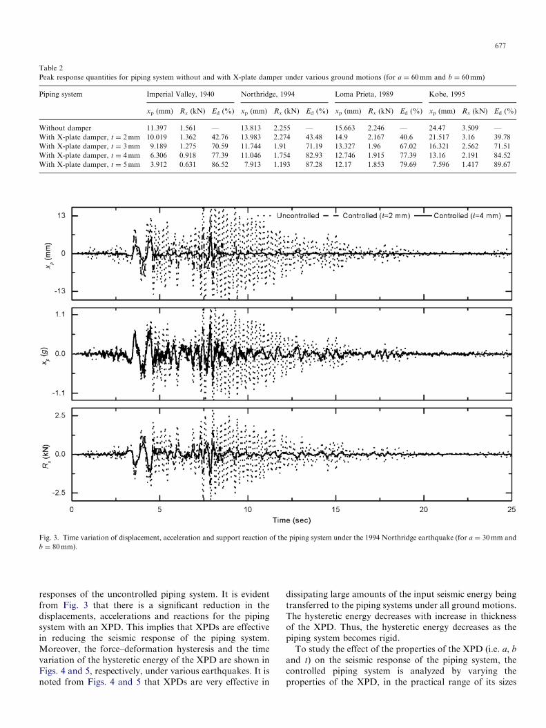
Fig. 3. Time variation of displacement, acceleration and support reaction of the piping system under the 1994 Northridge earthquake (for a ¼ 30mm and
b ¼ 80mm).
Table 2
Peak response quantities for piping system without and with X-plate damper under various ground motions (for a ¼ 60mm and b ¼ 60mm)
Piping system Imperial Valley, 1940 Northridge, 1994 Loma Prieta, 1989 Kobe, 1995
xp (mm) Rx (kN) Ed (%) xp (mm) Rx (kN) Ed (%) xp (mm) Rx (kN) Ed (%) xp (mm) Rx (kN) Ed (%)
Without damper 11.397 1.561 — 13.813 2.255 — 15.663 2.246 — 24.47 3.509 —
With X-plate damper, t ¼ 2mm 10.019 1.362 42.76 13.983 2.274 43.48 14.9 2.167 40.6 21.517 3.16 39.78
With X-plate damper, t ¼ 3mm 9.189 1.275 70.59 11.744 1.91 71.19 13.327 1.96 67.02 16.321 2.562 71.51
With X-plate damper, t ¼ 4mm 6.306 0.918 77.39 11.046 1.754 82.93 12.746 1.915 77.39 13.16 2.191 84.52
With X-plate damper, t ¼ 5mm 3.912 0.631 86.52 7.913 1.193 87.28 12.17 1.853 79.69 7.596 1.417 89.67
677
responses of the uncontrolled piping system. It is evidentfrom Fig. 3 that there is a significant reduction in thedisplacements, accelerations and reactions for the pipingsystem with an XPD. This implies that XPDs are effectivein reducing the seismic response of the piping system.Moreover, the force–deformation hysteresis and the timevariation of the hysteretic energy of the XPD are shown inFigs. 4 and 5, respectively, under various earthquakes. It isnoted from Figs. 4 and 5 that XPDs are very effective in
dissipating large amounts of the input seismic energy beingtransferred to the piping systems under all ground motions.The hysteretic energy decreases with increase in thicknessof the XPD. Thus, the hysteretic energy decreases as thepiping system becomes rigid.To study the effect of the properties of the XPD (i.e. a, b
and t) on the seismic response of the piping system, thecontrolled piping system is analyzed by varying theproperties of the XPD, in the practical range of its sizes

Fig. 4. Hysteresis loops of the XPD for the piping system under various real-earthquake ground motions.
Fig. 5. Time variation of the hysteretic energy for various thicknesses of the XPDs for the piping system under various real-earthquake ground motions.
678

Fig. 6. Effect of a, for various thicknesses of the XPDs, on the seismic responses of the piping system under various real-earthquake ground motions.
Fig. 7. Effect of b, for various thicknesses of the XPDs, on the seismic responses of the piping system under various real-earthquake ground motions.
679
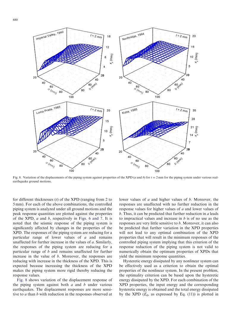
Fig. 8. Variation of the displacements of the piping system against properties of the XPD (a and b) for t ¼ 2mm for the piping system under various real-
earthquake ground motions.
680
for different thicknesses (t) of the XPD (ranging from 2 to5mm). For each of the above combinations, the controlledpiping system is analyzed under all ground motions and thepeak response quantities are plotted against the propertiesof the XPD, a and b, respectively in Figs. 6 and 7. It isnoted that the seismic response of the piping system issignificantly affected by changes in the properties of theXPD. The responses of the piping system are reducing for aparticular range of lower values of a and remainsunaffected for further increase in the values of a. Similarly,the responses of the piping system are reducing for aparticular range of b and remains unaffected for furtherincrease in the value of b. Moreover, the responses arereducing with increase in the thickness of the XPD. This isexpected because increasing the thickness of the XPDmakes the piping system more rigid thereby reducing theresponse values.
Fig. 8 shows variation of the displacement response ofthe piping system against both a and b under variousearthquakes. The displacement responses are more sensi-tive to a than b with reduction in the responses observed at
lower values of a and higher values of b. Moreover, theresponses are unaffected with no further reduction in theresponse values for higher values of a and lower values ofb. Thus, it can be predicted that further reduction in a leadsto impractical values and increase in b is of no use as theresponses are very little sensitive to b. Moreover, it can alsobe predicted that further variation in the XPD propertieswill not lead to any optimal combination of the XPDproperties that will result in the minimum responses of thecontrolled piping system implying that this criterion of theresponse reduction of the piping system is not valid tonumerically obtain the optimum properties of XPDs thatyield the minimum response quantities.Hysteretic energy dissipated by any nonlinear system can
be effectively used as a criterion to obtain the optimalproperties of the nonlinear system. In the present problem,the optimality criterion can be based upon the hystereticenergy dissipated by the XPD. For each combination of theXPD properties, the input energy and the correspondinghysteretic energy is obtained and the total energy dissipatedby the XPD (Ed, as expressed by Eq. (11)) is plotted in

Fig. 9. Effect of a on the hysteretic energy for various thicknesses of the XPDs for the piping system under various real-earthquake ground motions.
681
Figs. 9 and 10 against a and b, respectively. The dissipatedenergy is plotted for four thicknesses of the XPD. It isnoted that the hysteretic energy is significantly affected bychanges in the damper properties, a and b. Unlike thevariation of the responses of the piping system, the plot ofenergy dissipated shows a particular combination of theproperties of the XPD for which the percentage energydissipated is a maximum. It is observed that for each of thethicknesses of the XPD, the plot of percentage energydissipation against a (Fig. 9) shows a particular value of a
for which the maximum percentage energy dissipation in
the controlled piping system is obtained. Similarly, the plotof percentage energy dissipation against b (Fig. 10) shows aparticular value of b for which the maximum percentageenergy dissipation is observed. The present piping systemhas a static stiffness of 388198 kN/m at the damperlocation. For this piping system under the Imperial Valleyearthquake, Fig. 9 shows maximum energy dissipation of84.05% for an XPD of size a ¼ 30mm and b ¼ 60mm (i.e.having properties Kd ¼ 2488 kN/m, Fy ¼ 1.173 kN anda ¼ 0.0258). This implies that there exists a combination ofthe properties of XPD, which results in maximum energy

Fig. 10. Effect of b on the hysteretic energy for various thicknesses of the XPDs for the piping system under various real-earthquake ground motions.
682
dissipation in the controlled piping system. Moreover, it isobserved that the energy dissipation in the piping system ismore sensitive to the variation in a than b.
Fig. 11 shows the plot of percentage energy dissipated inthe controlled piping system against the properties of theXPD. It is confirmed from Fig. 11 that there exists a certaincombination of the properties of the XPD for which themaximum energy dissipation is obtained. However, it is tobe noted here that the optimal combination of theproperties of XPD obtained is not the global optimalsolution and varies with respect to the given piping layout.Thus, there exist different solutions dependent on the type,
layout and the earthquake excitation used for analyzing thepiping system.Application of XPDs in a piping system increases the
stiffness of the entire system depending on the number ofXPDs used. Though the stiffness of an individual XPDmay be small compared to the stiffness of the pipingsystem, it affects the free vibration characteristics of thepiping system. Moreover, using a large number of XPDs ina piping system will significantly affect the free vibrationcharacteristics of the piping system. Therefore, to study theeffect of the properties of the XPD on the free vibrationcharacteristics of the piping system, the fundamental

Fig. 11. Variation of the hysteretic energy in the XPD against properties of the XPD (a and b) for the piping system under various real-earthquake ground
motions.
683
frequency of the piping system is plotted in Fig. 12 againstthe damper properties, a and b. The frequencies are plottedfor two sizes of XPD and for four thicknesses. It is observedthat the frequency of the piping system is notably affectedby change in b and is very sensitive to a, where significantreduction in the frequency is noted with increase in a. This isexpected as increasing a makes the piping system moreflexible and reduces the natural frequency whereas increasein the thickness of the XPD makes the piping system rigidthereby increasing the natural frequency. The effect of a andb on the natural frequency of the piping system is crucial asit may bring the system into the zone of high accelerationamplitudes of the input ground motions, consequentlyattracting more earthquake forces.
8. Conclusions
A numerical study is presented in this paper thatinvestigates the seismic effectiveness of the X-plate damper(XPD) for piping systems in industrial installations. Theseismic responses of a spatial piping system are thenstudied under important parametric variation of the
damper properties under real earthquake ground motionsto obtain the optimum properties of the XPD. The damperproperties considered are height, width and thickness of theXPD. The effect of damper parameters on the responsequantities of the piping system is studied for damper widthand height in the practical range of 20–100mm for fourdifferent thicknesses of the XPD in the range of 2–5mm.However, it is observed that the criterion to obtain minimalresponse quantities with variation in the damper propertiesdoes not yield any optimal solution. Therefore, the role ofthe hysteretic energy dissipated by the XPD is also studiedby using the percentage energy dissipation in the pipingsystem as a criterion to decide the optimal combination ofthe properties of the XPD. The effect of the damperproperties on the natural frequency of the piping system isalso investigated. Based on the trends of the results, thefollowing conclusions are drawn.
(1)
XPDs are very effective in reducing the seismicresponse of piping systems.(2)
The effectiveness of the XPD increases as the percen-tage energy dissipated by the XPD increases, implying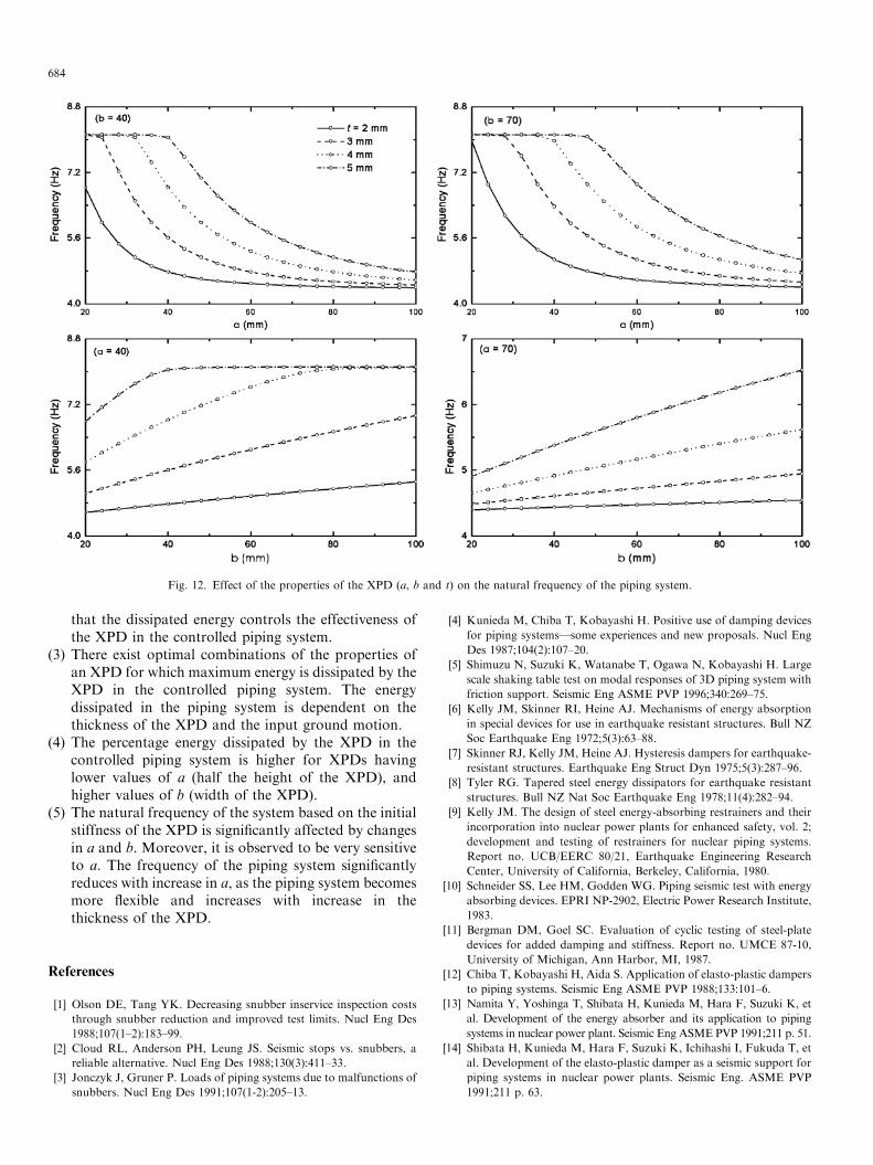
Fig. 12. Effect of the properties of the XPD (a, b and t) on the natural frequency of the piping system.
684
that the dissipated energy controls the effectiveness ofthe XPD in the controlled piping system.
(3)
There exist optimal combinations of the properties ofan XPD for which maximum energy is dissipated by theXPD in the controlled piping system. The energydissipated in the piping system is dependent on thethickness of the XPD and the input ground motion.(4)
The percentage energy dissipated by the XPD in thecontrolled piping system is higher for XPDs havinglower values of a (half the height of the XPD), andhigher values of b (width of the XPD).(5)
The natural frequency of the system based on the initialstiffness of the XPD is significantly affected by changesin a and b. Moreover, it is observed to be very sensitiveto a. The frequency of the piping system significantlyreduces with increase in a, as the piping system becomesmore flexible and increases with increase in thethickness of the XPD.References
[1] Olson DE, Tang YK. Decreasing snubber inservice inspection costs
through snubber reduction and improved test limits. Nucl Eng Des
1988;107(1–2):183–99.
[2] Cloud RL, Anderson PH, Leung JS. Seismic stops vs. snubbers, a
reliable alternative. Nucl Eng Des 1988;130(3):411–33.
[3] Jonczyk J, Gruner P. Loads of piping systems due to malfunctions of
snubbers. Nucl Eng Des 1991;107(1-2):205–13.
[4] Kunieda M, Chiba T, Kobayashi H. Positive use of damping devices
for piping systems—some experiences and new proposals. Nucl Eng
Des 1987;104(2):107–20.
[5] Shimuzu N, Suzuki K, Watanabe T, Ogawa N, Kobayashi H. Large
scale shaking table test on modal responses of 3D piping system with
friction support. Seismic Eng ASME PVP 1996;340:269–75.
[6] Kelly JM, Skinner RI, Heine AJ. Mechanisms of energy absorption
in special devices for use in earthquake resistant structures. Bull NZ
Soc Earthquake Eng 1972;5(3):63–88.
[7] Skinner RJ, Kelly JM, Heine AJ. Hysteresis dampers for earthquake-
resistant structures. Earthquake Eng Struct Dyn 1975;5(3):287–96.
[8] Tyler RG. Tapered steel energy dissipators for earthquake resistant
structures. Bull NZ Nat Soc Earthquake Eng 1978;11(4):282–94.
[9] Kelly JM. The design of steel energy-absorbing restrainers and their
incorporation into nuclear power plants for enhanced safety, vol. 2;
development and testing of restrainers for nuclear piping systems.
Report no. UCB/EERC 80/21, Earthquake Engineering Research
Center, University of California, Berkeley, California, 1980.
[10] Schneider SS, Lee HM, Godden WG. Piping seismic test with energy
absorbing devices. EPRI NP-2902, Electric Power Research Institute,
1983.
[11] Bergman DM, Goel SC. Evaluation of cyclic testing of steel-plate
devices for added damping and stiffness. Report no. UMCE 87-10,
University of Michigan, Ann Harbor, MI, 1987.
[12] Chiba T, Kobayashi H, Aida S. Application of elasto-plastic dampers
to piping systems. Seismic Eng ASME PVP 1988;133:101–6.
[13] Namita Y, Yoshinga T, Shibata H, Kunieda M, Hara F, Suzuki K, et
al. Development of the energy absorber and its application to piping
systems in nuclear power plant. Seismic Eng ASME PVP 1991;211 p. 51.
[14] Shibata H, Kunieda M, Hara F, Suzuki K, Ichihashi I, Fukuda T, et
al. Development of the elasto-plastic damper as a seismic support for
piping systems in nuclear power plants. Seismic Eng. ASME PVP
1991;211 p. 63.

685
[15] Whittaker AS, Bertero VV, Thompson CL, Alonso LJ. Seismic
testing of steel plate energy dissipation devices. Earthquake Spectra
1991;7(4):563–604.
[16] Aiken AD, Nims DK, Whittakar AS, Kelly JM. Testing of passive
energy dissipation systems. Earthquake Spectra 1993;9(3):335–70.
[17] Namita Y, Yoshinga T, Shibata H, Kunieda M, Hara F, Suzuki K, et
al. Development of energy absorber and its application to piping
system in nuclear power plants. J Press Vessel Piping Div ASME
1997;211:51–7.
[18] Parulekar YM, Reddy GR, Vaze KK, Kushwaha HS. Elasto-plastic
damper for passive control of seismic response of piping systems.
BARC Internal Report no. BARC/2003/E/028, Reactor Safety
Division, BARC, Mumbai, 2003.
[19] Bakre SV, Jangid RS. Simplified seismic analysis of piping systems
with energy dissipating devices. Project no. 2002/36/7-BRNS/469,
Indian Institute of Technology, Bombay, 2004.
[20] Wen YK. Methods of random vibration for inelastic structures. Appl
Mech Rev ASME 1989;42(2):39–52.


![Optimum seismic design of concentrically braced steel ...eprints.whiterose.ac.uk/92308/1/Optimum Seismic Design of... · pattern suggested by UBC1997 [6]. It has been concluded that:](https://img.dokumen.tips/doc/110x75/5b6a01d27f8b9a9f1b8b9cb4/optimum-seismic-design-of-concentrically-braced-steel-seismic-design-of.jpg)