Embed Size (px)
Citation preview

Viscous Fluid Dampers Shock Transmission Units Preloaded Spring Dampers
Seismic Shock Absorbers Dampers For Cable Stays
FIDH Group
FIDH Group
Viscous Fluid Dampers for Seismic & Civil Engineering Industries
Designing & ManagingHydraulic Systems Solutions

2
A family legacy, a worldwide presence
ince 1950, Douce-Hydro has designed and manufactured
hydraulic cylinders and systems for all kind of industries, from the
standard to the most technological or heavy duty cylinder.
Since 1990, the company has been a family owned business, operated
by its dynamic CEO Mr Jean-Marc Vandenbulke, which perennity
is ensured into the future with the accesssion of his son Mr. Franck
Vandenbulke at the head of the US Headquarters in 2000, and since
2009, also as the Executive Vice-President.
Within the scope of its signifi cant international expansion, the
companies Douce-Hydro Inc. and Douce-Hydro GmbH have been
created respectfully in the USA in 1996 and in Germany in 2007.
In July 2008, Douce-Hydro acquired Jarret Structures brand, trademark
and patents for viscous fl uid dampers for the seismic and civil
engineering industries, extending its range of products.
Jarret Structures offers a wide range of patented damping devices
and, by utilizing its extensive design software, test and simulation
capabilities, has the ability to create specialized products to meet
complex and unique shock absorption application requirements.
Through both internal research and research programs carried out
with large universities worldwide, Jarret Structures is able to offer
technically innovative and commercially viable solutions to most
shock absorption problems.
S
Mr Franck VandenbulkeExecutive Vice-President Douce-Hydro SAS
General Manager Douce-Hydro Inc. USAGeneral Manager Jarret Structures Inc. USA
Mr Jean-Marc VandenbulkeCEO FIDH GroupCEO Douce-Hydro SASCEO Douce-Hydro Inc. USACEO Douce-Hydro GmbH GermanyCEO Jarret Structures Inc. USA

3
EXCELLENCE EXPERIENCE EXPERTISE EFFICIENCY
Mr Jacky VandenbulkeProduction manager
Douce-Hydro SAS
Ms Anne-Frédérique LeroyExport Manager
Douce-Hydro SAS
Mr Daniel MétaisFinancial Director Douce-Hydro SAS
Mrs Marcelina CozetteSales Manager FranceDouce-Hydro SAS
Mrs Mathilde Gillet-VandenbulkeSales Manager Douce-Hydro Inc. USASales Manager Jarret Structures Inc. USA
O R G A N I S A T I O N C H A R T
FIDH GROUP
Douce-Hydro SAS (France)
Jarret Structures Division
Worldwide HeadquartersDesign and Manufacturing
Douce-Hydro Inc. (USA)
Jarret Structures Inc (USA)
North American HeadquartersSales Office, Repair & Warehouse Facility
Douce-Hydro GmbH (Germany)
German and Austrian HeadquartersSales Office

4
EXCELLENCE EXPERIENCE EXPERTISE EFFICIENCY
Engineering
WE ARE THE EXPERTSAs the world leader in design and manufacturing of custom viscous fl uid dampers, hydraulic cylinders and systems, Douce-Hydro helps its customers meet their challenges with industry leading edge solutions.
20 design engineers and technicians.
Over 60 years of technical experience and customer feedback.
CAD-CAM Siemens NX mechanical design software allowing delivery of industry-leading design
results, superior power, productivity, fl exibility, and coordination for product and design
development.
Finite Element Analysis (FEA), fatigue analysis, 2D and 3D designs.
Ability to create specialized products to meet complex and unique shock absorption application
requirements.
Cost-effective design methodology.
Research and development: diligent and highly creative research team, constantly innovating
unmatched solutions aligned with emerging requirements.
Mr André EncinasProduction Manager
Mr Adrien BrioyEngineer – Project Manager

5
PROJECT MANAGEMENT: The Douce-Hydro DifferencePre-project review.
Constant and open communication with our customers: dedicated and experienced team composed of a project manager, engineers and designers for each project.
Developing new systems and solutions: bringing integrated solutions tailored to our customer’s most demanding requirements and ensuring that our customers benefi t from solutions which are continuously evolving and improving.
Specifi cation management and project follow-up: offering the most advanced support to our customer, working hand-in-hand, from project initiation to delivery and on-site installation.
Extensive experience with third party certifying organizations such as ABS, Bureau Veritas, DNV, Germanischer Lloyd, Lloyd’s Register, TÜV and US Army Corps of Engineers, etc...
Engineering
Following customers requirements, we can manufacture according to European Norm EN15129 and have the dampers receive CE certifi cation.

6
Customer
Project Management TeamProject review
Feasibility analysisDesign proposal
Cost analysis - Project quoteProject delivery time analysis
Customer Approval – Purchase order
Project initiation – Kick off meeting
Project Requirements Project Communication
Project Management and Engineering System
EngineeringDevelopment of customized
solution and systemsAssembly drawings Detailed drawingsCalculationt notes
Finite Element Analysis (FEA)FAT testing procedureMaintenance manual
Safety review and process
QualityManagement
Inspection test planFull traceability
Materials certifi catesCommissioning
Record manufacturing data bookSafety review and process
Shipping ManagementLogistic and shipping procedures
Packing proceduresManaging domestic and international
shipmentsManaging customs worldwide
Service ManagementStart-up installation on-site support
Worldwide technical assistanceFollow-upAfter-sales
ProcessManagement
Planning/Project updateManufacturing processes
Welding procedure qualifi cation record procedure
Welding procedure specifi cationPaint procedure
7
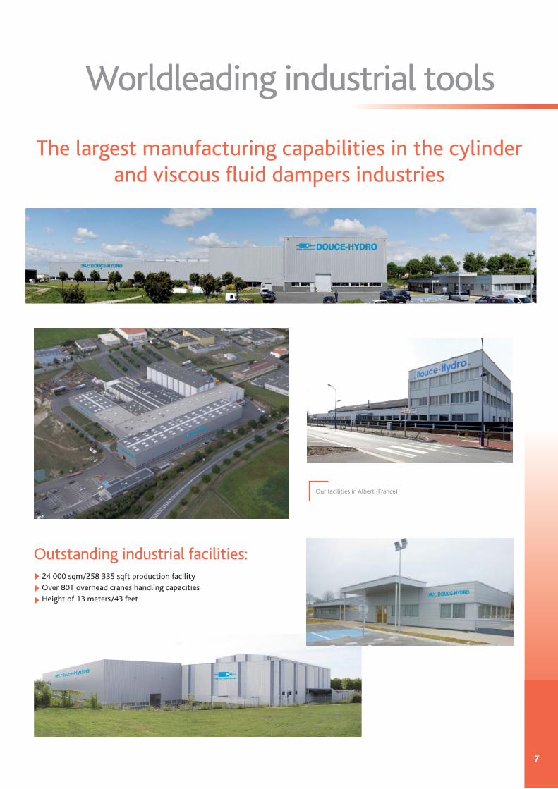
Worldleading industrial tools
The largest manufacturing capabilities in the cylinder and viscous fl uid dampers industries
Outstanding industrial facilities: 24 000 sqm/258 335 sqft production facilityOver 80T overhead cranes handling capacitiesHeight of 13 meters/43 feet
Our facilities in Albert (France)

8
Manufacturing capabilities
CNC Turning Lathe
Maximal dimensions
Turning & Boring94.5” external dia. 89 feet in length
48” inside dia.89 feet in length
57 feet in length17 feet high8 feet wide
51” diameter98 feet in length
35” diameter80 feet in length
TIG / GTAW (Gas Tungsten Arc Welding), MIG / GMAW(Gas Metal Arc Welding), SAW (Submerged Arc Welding)
2 690 sqft
Honing (vertical)
Milling & Drilling
Grinding
Polishing
Welding
Painting
Hydraulic testcapabilities
Capacity: 2 110 gallonsFlow: 124 gal/min
Power: 50 kWBooster Pump: 10 150 PSI
2,4 m external dia. 27 m in length
1,2 m inside dia.27 m in length
17 230 mm in length5 060 mm high2 350 mm wide
1 900 mm diameter27 m in length
900 mm diameter24 m in length
250 sqm
Capacity: 8 000 litresFlow: 470 litres/min
Power: 50 kWBooster Pump: 700 bar
Up to 1,2 meters/48” bore dia.Up to 2,4 meters/94.5” external dia.Up to 27 meters/89 feet in length
Grinding machine:Diameter: 900 mm/35 inchesLength: 30 000 mm/98 feetOne of the largest grinding machines in Europe !

9
State-of-the art, digitally computerized (CNC) & competitive machineries park.Douce-Hydro / Jarret Structures owns some of the largest equipment available in the world for the manufacture of hydraulic cylinders, piston accumulators and viscous fl uid dampers.
Worldleading industrial tools
5-AXIS CNC lathe/Tour CNC à 5 axesSwing over top slide: 900 mm/35 inchesMaximal center distance: 6 500 mm/21 feet
Centerless polisherDia. 60 up to 500 mmLength: 10 000 mmAllowable weight: 17 000 kg
Large dimensions vertical honing machine Automatic welding bench
Heavy duty CNC lathe
10
Improving business performance and manufacturing excellence
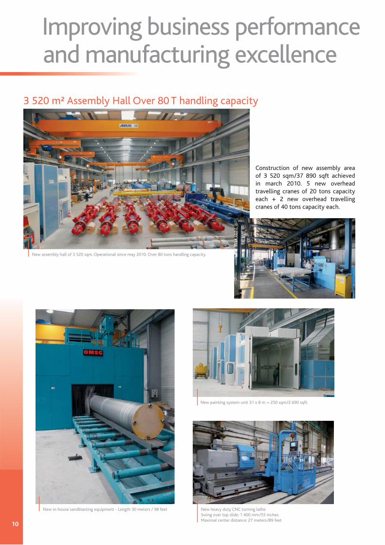
3 520 m² Assembly Hall Over 80 T handling capacity
Construction of new assembly area of 3 520 sqm/37 890 sqft achieved in march 2010. 5 new overhead travelling cranes of 20 tons capacity each + 2 new overhead travelling cranes of 40 tons capacity each.
New assembly hall of 3 520 sqm. Operational since may 2010. Over 80 tons handling capacity.
New painting system unit 31 x 8 m = 250 sqm/2 690 sqft.
New heavy duty CNC turning latheSwing over top slide: 1 400 mm/55 inchesMaximal center distance: 27 meters/89 feet
New in-house sandblasting equipment - Length 30 meters / 98 feet

11
eveloped by Douce-Hydro “Research & Development” team, KERADOUCE® is a multilayer coating, waterproof and very hard, which is applied on the rods of hydraulic cylinders and dampers, and has an excellent corrosion resistance. It is homogeneous, uninterrupted, non conducting, fl exible enough to support functional rod bending, and ecological.
Since 1990, with thousands of hydraulic cylinders and dampers in use worldwide, our KERADOUCE® coating has proved its high effi ciency and reliability.
®
VERY HIGH CORROSION RESISTANCE REPLACES NICKEL-CHROME
D
Test results after 2 000 hours in salt spray test
Corrosion resistance
Scratch resistance
Abrasion resistance
Wear resistance
Elasticity
Impact resistance
Surface finish (Ra/Rt)
Chrome NickelChrome KERADOUCE®
Standard thickness 300 µm
Ra = 0.1 to 0.2 µm
>50 Mpa = 7 250 psi
2 000 hours minimum
Corrosive environments,extreme environmental
conditions such asmarine, seaports,
offshore, steel works...
900 HV = 67 HRC(Rockwell C)Hardness
Standard surface finish
Adherence following normNFEN 582
Corrosion resistance into acetic salt spray test (ASTM B 117 & 287, NF ISO 9227,
NF ISO 3769)
Application types
Mechanical Characteristics
ASR 300 -150-230 with KERADOUCE® coatingBuilding bracing working in traction and compression
Rod coating

12
Quality control
California offi ce buildings 8 & 9, Sacramento256 viscous fl uid dampers ASR 1500-108 AHConfi guration: Double acting, double rod, internal reservoirRated Load @ velocity: 275 Kips @ 0.391ft/secCharacteristic equation: F = [362 • V0.32] Kips, (±15% tolerance)Total stroke: 4.25 inches
Quality Process: Inspection test plan, safety review and process, full traceability, material certifi cates, commissioning, record manufacturing data book.
ISO 9001: 2008 certifi ed
Tests: Static pressure test, dynamic test, fatigue cycle test, NDE testings, cushioning simulation test bench, side load dynamic test, load pressure test, traction test as per DNV lifting appliance rules, liquid penetrant, custom testing following customer specifi cations.
Electronic chart recorder.
All our welders are certifi ed.
Dynamic test: 1300 kN
Total QualityManagement
Test example - Force/Velocity Damping Forces vs Velocity275 kips Nonliner Damper w/velocity exp.=0.32, C=362 kips(ft/s)^0.32
Dam
pin
g Fo
rce
[kip
s]
Velocity [ft/sec]
Nominal
(+15%)
(-15%)

13
BEFORE
AFTER
Retrofi t / DampersWorldwide technical assistance
A complete service, 7 days/weekDouce-Hydro/Jarret Structures has long recognized that «After-Sales Service» is a key element in achieving and maintaining customer satisfaction. To this end, the company has established 2 large repair centers staffed with a team of highly skilled service technicians: a large repair center staffed and a parts warehouse in Albert, France, adjacent to its modern production facilities, as well as a repair and warehouse center located in Michigan, USA, by Douce-Hydro Inc. In addition, Douce-Hydro is dedicated to offering its customers worldwide Technical Assistance: its highly skilled technicians can be sent anytime and anywhere in the world. Douce-Hydro/Jarret Structures can also offer supervision of work or witnessing of installations.
AFTER
BEFORE
14
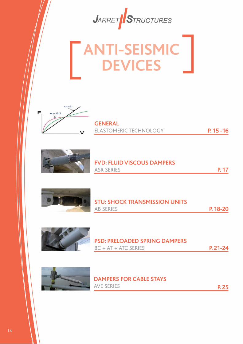
ANTI-SEISMIC DEVICES
GENERALELASTOMERIC TECHNOLOGY
FVD: FLUID VISCOUS DAMPERSASR SERIES
STU: SHOCK TRANSMISSION UNITSAB SERIES
PSD: PRELOADED SPRING DAMPERSBC + AT + ATC SERIES
DAMPERS FOR CABLE STAYSAVE SERIES
P. 15 -16
P. 17
P. 18-20
P. 21-24
P. 25

15
Technologies
Douce-Hydro/Jarret Structures' devices use special fl uids made of viscous silicon.
Our technology which has proven to be industrially successful over the
past 50 years, uses the fl uids characteristics to obtain device function.
Fluid characteristics
COMPRESSIBILITY
VISCOSITY
Device functions
SPRING Function
DAMPING Function
F = C.Vα
he force-velocity relationship of the non-linear dampers is given by F = C.Vα (C is the damping constant; V is the seismic relative velocity, and α is the damping exponent). This relationship is graphically illustrated below.
The graph above shows that, as a generalized behavior, the lower the alpha value (α), and the higher the velocity (V), the resulting force (F) will stabilize and will not increase any further, limiting structural stresses and displacements.
Thanks to the use of this silicon fl uid technology, Douce-Hydro/Jarret Structures’ is able to design for very low alpha values between 0.07 ≥ α ≥ 0.8, with alpha values in a range of 0.1 ≥ α ≥ 0.2 being the most common. Douce-Hydro/Jarret Structures’ approach allows for signifi cantly greater damping results and effi ciency.
BEHAVIOR LAW:
GEN
ERAL
FVD
: FLUID
VISC
OU
S DA
MPER
STU: SH
OC
K TRA
NSM
ISSION
UN
ITPSD
: PRELOA
D SPRIN
G D
AM
PERAV
E SERIES
T
F
V
α=0.1
α=1
16
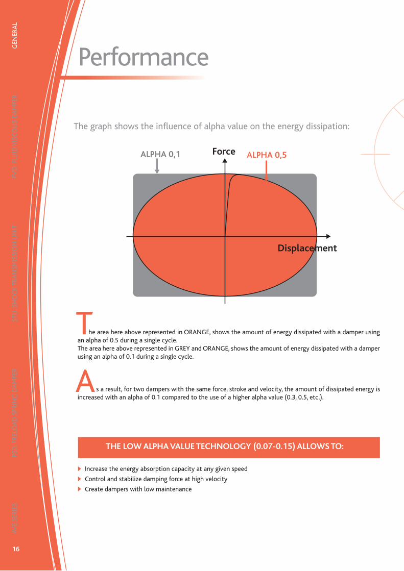
Performance
The graph shows the infl uence of alpha value on the energy dissipation:
ALPHA 0,5ALPHA 0,1
Displacement
he area here above represented in ORANGE, shows the amount of energy dissipated with a damper using an alpha of 0.5 during a single cycle.The area here above represented in GREY and ORANGE, shows the amount of energy dissipated with a damper using an alpha of 0.1 during a single cycle.
s a result, for two dampers with the same force, stroke and velocity, the amount of dissipated energy is increased with an alpha of 0.1 compared to the use of a higher alpha value (0.3, 0.5, etc.).
THE LOW ALPHA VALUE TECHNOLOGY (0.07-0.15) ALLOWS TO:
Increase the energy absorption capacity at any given speed
Control and stabilize damping force at high velocity
Create dampers with low maintenance
Force
GEN
ERA
LFV
D: F
LUID
VIS
CO
US
DA
MPE
RST
U: S
HO
CK
TRA
NSM
ISSI
ON
UN
ITPS
D: P
RELO
AD
SPR
ING
DA
MPE
RAV
E SE
RIES
T
A

17
FVD: Fluid Viscous DampersASR Series
Douce-Hydro/Jarret Structures’ damper is designed to dissipate seismic or dynamic energy on a structure. Douce-Hydro’s/Jarret Structures’ ASR series dampers work in tension and compression. The dampers can reduce longitudinal and transversal or vertical displacement of a deck. They can be installed in different type of structures, for example, longitudinally between the deck and the abutment, or in transverse between the deck and the pier structure of a bridge. They can equally be installed in a building for brace or base isolation. Seismic energy is dissipated into the damper unit instead of being dissipated in the concrete or steel structure.
F = C.VαBEHAVIOR LAW:
Working Principle:Douce-Hydro/Jarret Structures’ viscous fl uid damper works on the principle that rapid fl ow of viscous fl uid through a narrow orifi ce or port, generates high resistance, which then dissipates a large amount of energy. The energy is dissipated in heat.
Force depends on velocity
DynamicReaction
Reaction atlow velocity
x
F F = Pressure x SurfaceF = (P1-P2) x Sdiff(P1-P2) depends on fl ow into Vf, fi xed by the velocity.
P1, P2: internal pressure into the chambersVf: fl uid velocity into the gapSdiff: surface of the piston where the pressure is applied.
GEN
ERAL
FVD
: FLUID
VISC
OU
S DA
MPER
STU: SH
OC
K TRA
NSM
ISSION
UN
ITPSD
: PRELOA
D SPRIN
G D
AM
PERAV
E SERIES
A

18
Shock Transmission UnitsAB Series
Shock Transmission Unit (STU), also called Dynamic Connector, is designed to be connected between bridge structure components to form a rigid link under dynamic loads induced by forces such as vehicle braking and earthquakes. At the same time, the structure will be able to move freely under slowly applied loads such as thermal expansion and creep shrinkage.The unit is connected between elements of bridge structures at expansion joints, or near the bearings between the superstructure and the substructure.The use of STU allows the load sharing of a suddenly applied force.
A
A special valve is fi xed between the 2 chambers
F
XP1, P2 internal pressure into the chambersV<Vcut : F<10% x Fmax (thermal expansion possible)V>Vcut : F=Fmax (the structure is locked under a minimal displacement)
STU acts as a very stiff spring in dynamic loading (during earthquake or braking)
Working Principle:A STU should block the deck of a bridge during a quick motion and behave like a spring with a very high stiffness to reduce the displacement. At the same time, the Shock Transmission Unit should deliver a low reaction force during the slow displacements of thermal expansion or contraction of the deck.
GEN
ERA
LFV
D: F
LUID
VIS
CO
US
DA
MPE
RST
U: S
HO
CK
TRA
NSM
ISSI
ON
UN
ITPS
D: P
RELO
AD
SPR
ING
DA
MPE
RAV
E SE
RIES
Vcut
V>Vcut

19
Performance:The graph below shows the performance generated by an STU at low velocity, and during a dynamic event at high velocity. The Douce-Hydro/Jarret Structures' AB series are velocity dependant.
Temperature and Aging:A variation of the outside temperature, which can range from - 55ºC to + 80ºC, does not change the damper's characteristics. There is no aging of the silicone fl uid. The Douce-Hydro/Jarret Structures' AB units have been tested in very severe environmental conditions, including fi re.
GEN
ERAL
FVD
: FLUID
VISC
OU
S DA
MPER
STU: SH
OC
K TRA
NSM
ISSION
UN
ITPSD
: PRELOA
D SPRIN
G D
AM
PERAV
E SERIES
Shock Transmission UnitsAB Series
THEORETICAL FORCE / STROKE DIAGRAMME
Force (kN)
Course (mm)
Free displacement at low velocity (force <10% nominal force (Fmax)), Velocity < 0,05mm/s (thermal expansion)
Blocking Force, when the velocity increases (0,05mm/s< Velocity < 0,15mm/s), the force grows up with very high stiffness (during braking or earthquake)
Traction Rdyn
Compression Rdyn
Vcut
Fmax

20
GEN
ERA
LFV
D: F
LUID
VIS
CO
US
DA
MPE
RST
U: S
HO
CK
TRA
NSM
ISSI
ON
UN
ITPS
D: P
RELO
AD
SPR
ING
DA
MPE
RAV
E SE
RIES
FVD and STU Dimensions
Dampers Stroke Y X ØC E NxØD A / B Ea / Eb
ASR 300 Fmax = 300 kN Alpha = 0.1
ASR 300 - 100 50 961 801 140 25 4xØ20 200 150
ASR 300 - 500 250 1 961 1 801 140 25 4xØ20 200 150
ASR 650 Fmax = 650 kN Alpha = 0.1
ASR 650 - 100 50 1172 942 160 30 4xØ27 250 180
ASR 650 - 500 250 2172 1 942 180 30 4xØ27 250 180
ASR 1000 Fmax = 1 000 kN Alpha = 0.1
ASR 1000 - 100 50 1 478 1 158 200 40 4xØ33 300 220
ASR 1000 - 500 250 2 478 2 158 225 40 4xØ33 300 220
ASR 1500 Fmax = 1 500 kN Alpha = 0.1
ASR 1500 - 100 50 1 517 1 197 255 45 4xØ39 350 255
ASR 1500 - 600 300 2 767 2 447 280 45 4xØ39 350 255
ASR 2000 Fmax = 2 000 kN Alpha = 0.1
ASR 2000 - 100 50 1 740 1 330 325 55 6x44 400 290
ASR 2000 - 600 300 2 990 2 580 360 55 6x44 400 290
+-+-+-+-
+-
+-
+-
+-
+-
+-The range of dampers size is not limited, we can design dampers following your request, for example 2 000 kN, 3 000 kN, 4 000 kN, 5 000 kN...Do not hesitate to contact us to obtain more details and explanations.
Others designs :
Installation :We can provide our dampers with different accessories such as :
AnchorsSliding plates (stainless steel plates)Mounting boltsEtc.
Appuis sur chaques faces
ASRASR
Appuis sur chaques faces
mm mm mmmm mm mm mm mm

21
Preloaded Spring Dampers
GEN
ERAL
FVD
: FLUID
VISC
OU
S DA
MPER
STU: SH
OC
K TRA
NSM
ISSION
UN
ITPSD
: PRELOA
D SPRIN
G D
AM
PERAV
E SERIES
PSD Series
Working Principle:The PSD works on the principle that rapid fl ow of viscous fl uid through a narrow orifi ce or port, generates high resistance, which then dissipates a large amount of energy. The energy is dissipated in heat. In order to avoid the displacement before reaching a certain force level, Douce-Hydro/Jarret Structures can defi ne a preloaded value, F0. Before reaching this value it is not possible to compress the unit. After the dynamic compression of the PSD, the unit has the ability to return to its original position due to the integrated spring function. For example, this return force value is defi ned in order to overcome the friction force of the sliding pot bearings. In order to generate this damping and spring function in two directions, a double-acting PSD is used.
BEHAVIOR LAW:
AT10S-2000ELinkspan « Quai des Flotilles » in France.
F = F0 + KX + CV α
Staticreaction
Dynamicreaction

22
GEN
ERA
LFV
D: F
LUID
VIS
CO
US
DA
MPE
RST
U: S
HO
CK
TRA
NSM
ISSI
ON
UN
ITPS
D: P
RELO
AD
SPR
ING
DA
MPE
RAV
E SE
RIES
Preloaded Spring Dampers
Spring function
Preloaded + Spring function
Preloaded + Spring function + Damping
F = FO + K(x)
F = FO + K(x)+CVα
F = K(x)F = PXS
- We use Preloaded Spring Damper- We add a head to the piston to obtain damping
Internal Pressure Increases
Force
Displacement (X)
Force
F0
Displacement (X)
Force
F0
Displacement (X)
CVα
K(x)
K(x)
K(x)
Design layouts of the different functions:
23
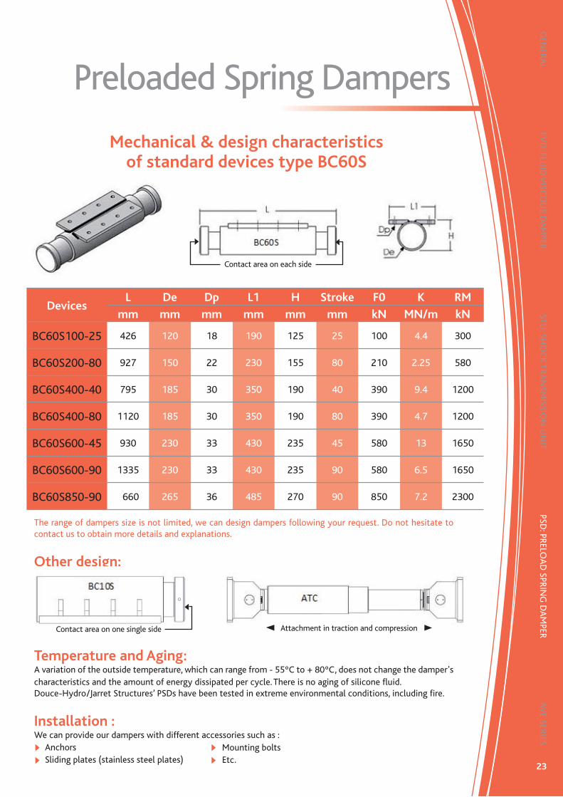
Preloaded Spring Dampers
Mechanical & design characteristics of standard devices type BC60S
DevicesL De Dp L1 H Stroke F0 K RM
mm mm mm mm mm mm kN MN/m kN
BC60S100-25 426 120 18 190 125 25 100 4.4 300
BC60S200-80 927 150 22 230 155 80 210 2.25 580
BC60S400-40 795 185 30 350 190 40 390 9.4 1200
BC60S400-80 1120 185 30 350 190 80 390 4.7 1200
BC60S600-45 930 230 33 430 235 45 580 13 1650
BC60S600-90 1335 230 33 430 235 90 580 6.5 1650
BC60S850-90 1660 265 36 485 270 90 850 7.2 2300
The range of dampers size is not limited, we can design dampers following your request. Do not hesitate to contact us to obtain more details and explanations.
Other design:
Temperature and Aging:A variation of the outside temperature, which can range from - 55ºC to + 80ºC, does not change the damper's characteristics and the amount of energy dissipated per cycle. There is no aging of silicone fl uid.Douce-Hydro/Jarret Structures’ PSDs have been tested in extreme environmental conditions, including fi re.
GEN
ERAL
FVD
: FLUID
VISC
OU
S DA
MPER
STU: SH
OC
K TRA
NSM
ISSION
UN
ITPSD
: PRELOA
D SPRIN
G D
AM
PERAV
E SERIES
Installation :We can provide our dampers with different accessories such as :
AnchorsSliding plates (stainless steel plates)
Contact area on each side
Contact area on one single side Attachment in traction and compression
Mounting boltsEtc.
24
GEN
ERA
LFV
D: F
LUID
VIS
CO
US
DA
MPE
RST
U: S
HO
CK
TRA
NSM
ISSI
ON
UN
ITPS
D: P
RELO
AD
SPR
ING
DA
MPE
RAV
E SE
RIES
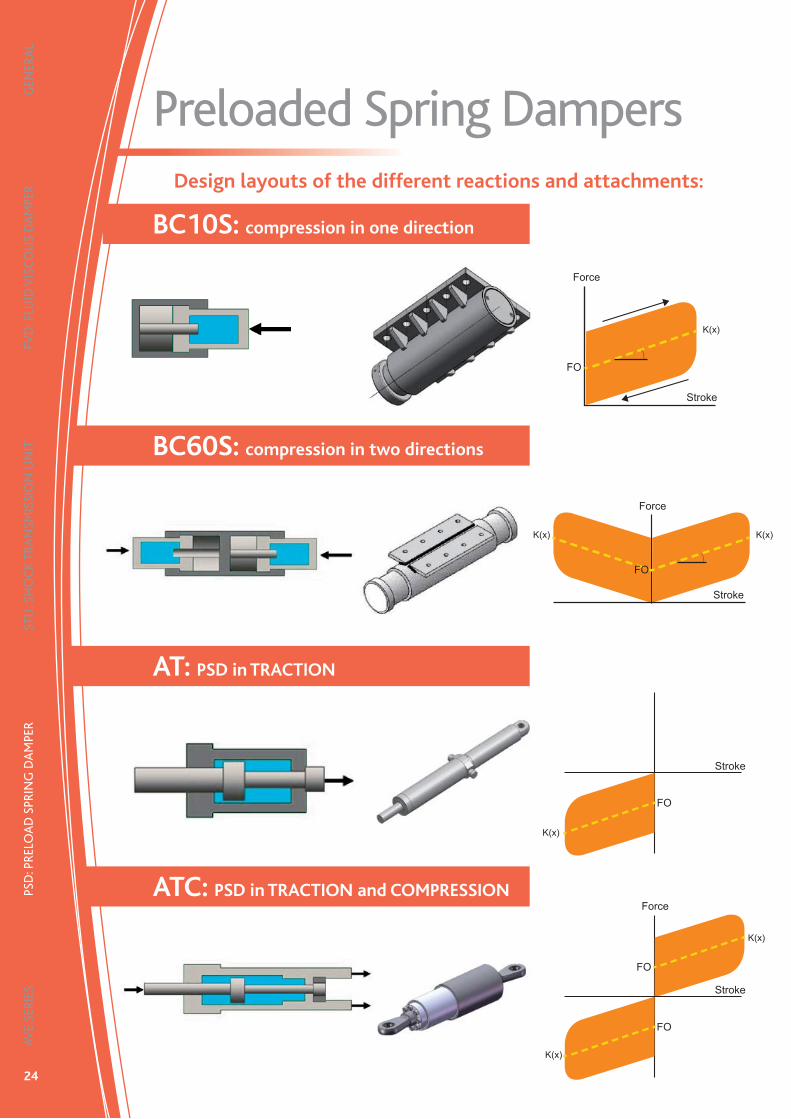
BC10S: compression in one direction
BC60S: compression in two directions
AT: PSD in TRACTION
ATC: PSD in TRACTION and COMPRESSION
Force
Force
Force
Stroke
Stroke
Stroke
Stroke
FO
K(x)
K(x)K(x)
K(x)
K(x)
K(x)
FO
FO
FO
FO
Preloaded Spring DampersDesign layouts of the different reactions and attachments:

25
GEN
ERAL
FVD
: FLUID
VISC
OU
S DA
MPER
STU: SH
OC
K TRA
NSM
ISSION
UN
ITPSD
: PRELOA
D SPRIN
G D
AM
PERAV
E SERIES
Dampers for cable staysAVE Series
Performance:The graphs below show the performance generated by the damper during a dynamic event at a frequency of 1 Hertz. The value of the velocity exponent of Douce-Hydro/Jarret Structures’ damper can vary from 0.3 to 2. As the velocity increases, the force increases.
Force
Forc
e
Displacement
Velocity
F=C.V0,4
F=C.V0,6
F=C.V2
F=C.V1
UnitsL DØ Stroke RM Mass
mm mm mm KN KgAVE5-100 525 127 100 5 50
AVE6-100 525 127 100 6 50
AVE7-100 525 127 100 7 50
AVE8-100 525 127 100 8 50
AVE9-100 525 127 100 9 50
AVE10-100 525 127 100 10 50
AVE12-100 525 127 100 12 50
AVE15-100 525 127 100 15 50
AVE20-100 525 127 100 20 50
AVE25-100 525 127 100 25 50
AVE30-100 525 127 100 30 50
AVE35-100 525 127 100 35 50
AVE40-100 525 127 100 40 50
AVE45-100 525 127 100 45 50
AVE50-100 525 127 100 50 50
AVE55-100 525 127 100 55 50
AVE60-100 525 127 100 60 50
The range of dampers size is not limited, we can design dampers following your request.Do not hesitate to contact us to obtain more details and explanations.
Installation:A cable stay damper can be installed easily with standard anchors.
Maintenance:Douce-Hydro/Jarret Structures’ Cable Stay Dampers are maintenance free. A regular visual inspection can be done on periodic basis in order to check the corrosion protection system.

26 26
BUILDINGPROTECTION
BASE ISOLATION
WIND-BRACING BETWEEN FLOORS
CABLE BRACE ISOLATION SYSTEMTECHNOLOGY (CBIST)
P. 27
P. 28
P. 29-30
Douce-Hydro/Jarret Structures’ devices are easily adapted to meet the requirements of different types of structures:
As an energy dissipation device in a base isolation systemAs a reducer of inter-story drift for fl exible structures.

27
Base isolationApplication on individual
buildings
Working Principle:The base isolation is a solution to protect individual or small buildings. This system is a combination using isolators (Elastomeric plot) and dampers. The isolators reduce the force but increase the displacements. The dampers reduce the displacements by dissipating the energy. With this combination, the building structure is protected. The force and displacement transmitted at the foundation are reduced.
Dampers
Isolators
Impact of the base isolationon response spectra
Decrease of theacceleration
Isolator Reduce the rigidity
Dampers Dissipate energy
Without Dampers, the displacement are too high Dampers allow to reduce displacement
with Dampers
without Dampers
28
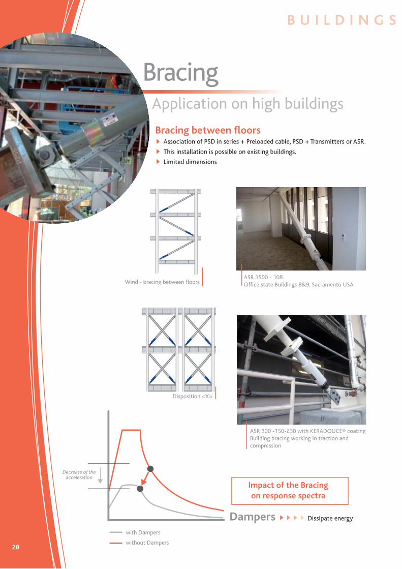
BracingApplication on high buildings
Bracing between fl oorsAssociation of PSD in series + Preloaded cable, PSD + Transmitters or ASR.
This installation is possible on existing buildings.
Limited dimensions
Wind - bracing between fl oorsASR 1500 - 108Offi ce state Buildings 8&9, Sacramento USA
Disposition «X»
ASR 300 -150-230 with KERADOUCE® coatingBuilding bracing working in traction and compression
Impact of the Bracingon response spectra
Decrease of theacceleration
Dampers Dissipate energy
with Dampers
without Dampers
B U I L D I N G S

29
CBIST:Cable Brace Isolation System Technology
New technology to protect structures
Cable Brace Isolation System (CBIST) installation Preloaded Spring Damper position at the base
Working Principle:The Cable Brace Isolation System Technology (CBIST) objective is to dissipate the energy in case of earthquake through the development of an innovative system based on a series of tension spring dampers and pre-stressed cables.
Principle Energy dissipation
1
4
5
3
2
1 retainer2 barrel3 piston4 silicon fl uid5 cable or transmitter
P R O T E C T I O N S

30
Technique applicable to new structures and when retrofi tting older buildings against earthquake risks by using:
Dampers to dissipate the energyExternal cables to limit the inter-story drift
CBIST: Cable Brace Isolation System Technology
Building protected with CBIST
Advantages:Architectural design remains the same
Design improvement and simplifi cation
No internal modifi cation to the building
Increase of safety
No maintenance
Drift per story and acceleration are reduced signifi cantly during an earthquake
Cost reduction compared to other techniques
Technology innovation
Few repair after earthquake
Floor
Displacementbetween stories(mm)
20
1
2
3
4
5
40
Building protected with CBIST
Building without CBIST

31
BRIDGESPROTECTION
DAMPERS
STU: SHOCK TRANSMISSION UNITS
PRELOADED SPRING DAMPERS
DAMPERS FOR CABLE STAYS
SPECIAL DAMPERS FOR RAILWAY BRIDGE
P. 32-33
P. 34
P. 35
P. 36
P. 39

32
Dampers
egardless of the type of construction, Douce-Hydro/Jarret Structures creates dampers which dissipate a large part of the kinetic energy, allowing the displacement of the deck without damaging the abutments and the structure.
Protection by dampers:Longitudinally and transversally on abutments and the piers
R
Longitudinal protection
Longitudinal damper (F= 3000 kN; Stroke= 650 mm)High Speed Train railway bridge of Ventabren in France.
Transversal protection
Transversal Dampers (F= 500 kN; Stroke= 260 mm) Aiton Highway A43 bridge in France.
B R I D G E S
33
Improvements by using dampers
P R O T E C T I O N S
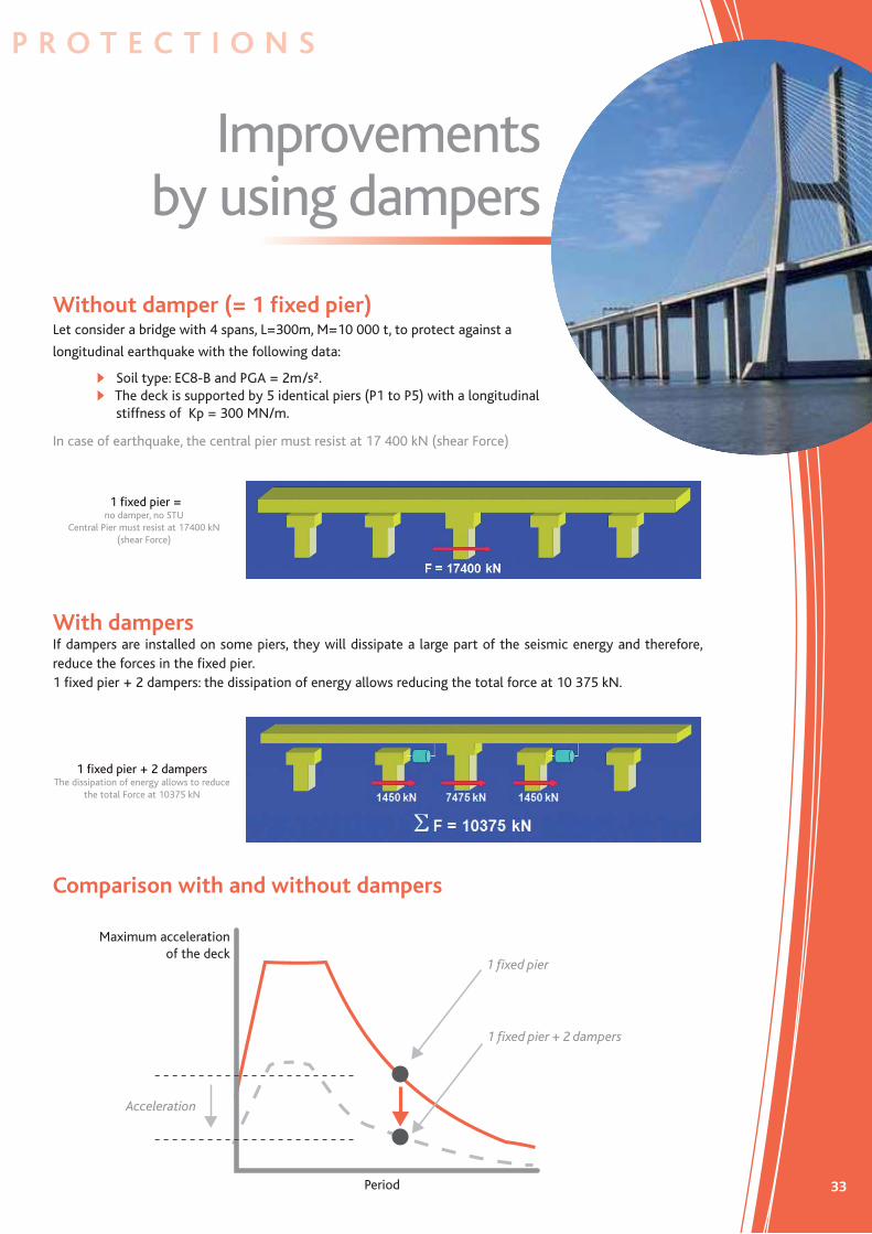
Without damper (= 1 fi xed pier)Let consider a bridge with 4 spans, L=300m, M=10 000 t, to protect against a
longitudinal earthquake with the following data:
Soil type: EC8-B and PGA = 2m/s². The deck is supported by 5 identical piers (P1 to P5) with a longitudinal stiffness of Kp = 300 MN/m.
In case of earthquake, the central pier must resist at 17 400 kN (shear Force)
With dampersIf dampers are installed on some piers, they will dissipate a large part of the seismic energy and therefore, reduce the forces in the fi xed pier.1 fi xed pier + 2 dampers: the dissipation of energy allows reducing the total force at 10 375 kN.
Comparison with and without dampers
1 fi xed pier = no damper, no STU
Central Pier must resist at 17400 kN (shear Force)
1 fi xed pier + 2 dampersThe dissipation of energy allows to reduce
the total Force at 10375 kN
Acceleration
1 fi xed pier
1 fi xed pier + 2 dampers
Maximum acceleration of the deck
Period
34
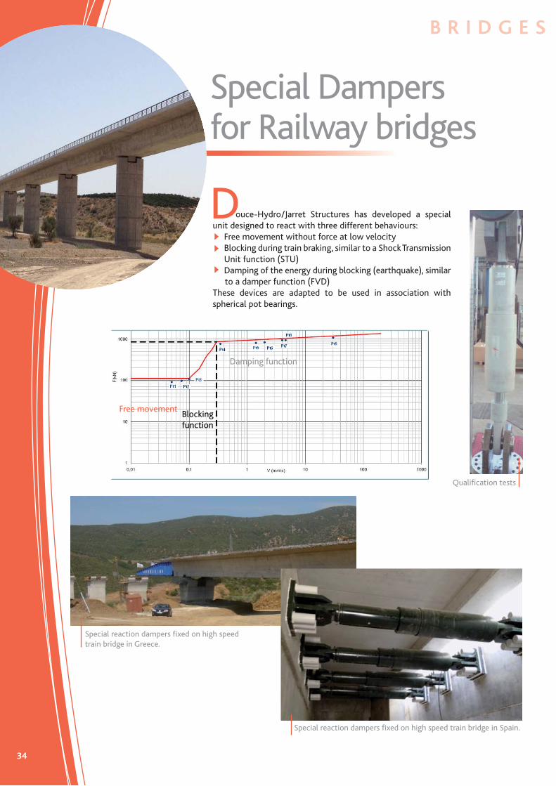
Special Dampers for Railway bridges
ouce-Hydro/Jarret Structures has developed a special unit designed to react with three different behaviours:
Free movement without force at low velocityBlocking during train braking, similar to a Shock Transmission Unit function (STU) Damping of the energy during blocking (earthquake), similar
to a damper function (FVD)These devices are adapted to be used in association with spherical pot bearings.
D
Special reaction dampers fi xed on high speed train bridge in Greece.
Free movement
Damping function
Blocking function
B R I D G E S
Special reaction dampers fi xed on high speed train bridge in Spain.
Qualifi cation tests
35
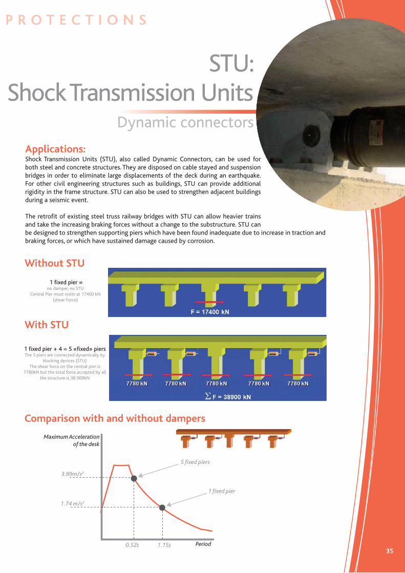
STU: Shock Transmission Units
P R O T E C T I O N S
Dynamic connectors
Without STU
With STU
Comparison with and without dampers
1 fi xed pier = no damper, no STU
Central Pier must resist at 17400 kN (shear Force)
1 fi xed pier + 4 = 5 «fi xed» piersThe 5 piers are connected dynamically by
blocking devices (STU)The shear force on the central pier is
7780kN but the total force accepted by all the structure is 38 900kN
1.74 m/s2
0.52s 1.15s
3.89m/s2
5 fi xed piers
1 fi xed pier
Period
Maximum Acceleration of the desk
Applications:Shock Transmission Units (STU), also called Dynamic Connectors, can be used for both steel and concrete structures. They are disposed on cable stayed and suspension bridges in order to eliminate large displacements of the deck during an earthquake. For other civil engineering structures such as buildings, STU can provide additional rigidity in the frame structure. STU can also be used to strengthen adjacent buildings during a seismic event.
The retrofi t of existing steel truss railway bridges with STU can allow heavier trains and take the increasing braking forces without a change to the substructure. STU can be designed to strengthen supporting piers which have been found inadequate due to increase in traction and braking forces, or which have sustained damage caused by corrosion.

36
PreloadedSpring dampers
Preloaded Spring Damper (PSD) is a unit designed to dissipate seismic energy on structures such as bridges. The PSD reduces longitudinal and transversal displacement of the deck. Douce-Hydro/Jarret Structures can provide two types of PSD: working in tension/compression, or acting only in compression. Douce-Hydro/Jarret Structures can install the PSD compression type longitudinally between the deck and the abutment, or install a PSD tension/compression unit in transversal position between the deck and the pier structure. The PSD acts as a shear key which has the possibility to regenerate itself automatically after a dynamic event. The seismic energy is dissipated in the PSD unit instead of being displaced in a steel or concrete structure. According to their position, these devices can accommodate transversal and longitudinal seismic displacement, and at the same time take into account longitudinal displacement such as creep shrinkage and thermal expansion or contraction.
A
Transversal PSD on the Deck. (F= 2200 kN, Stroke = 50mm)Motorway bridge A51, Viaduct of Monestier in France.
Transversal PSD (F= 2200 kN)St. André Viaduc, Fréjus in France
Longitudinal PSD on abutment(F = 2500 kN, Stroke = 50mm)High Speed railroad viaduct of Epenottes, France.
B R I D G E S

37
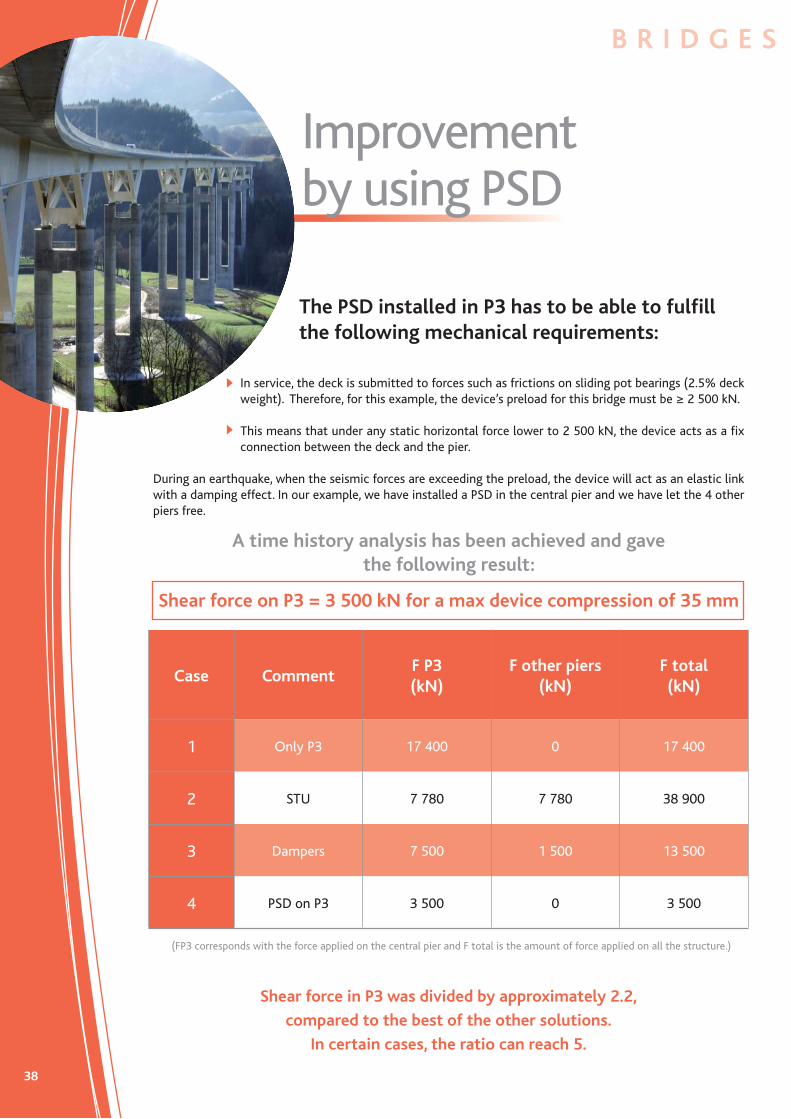
Improvement by using PSD
P R O T E C T I O N S
In the previous solutions, the central pier was fi xed.Using STU or dampers help us decrease shear in the fi xed pier but, when this pier is too stiff, their effi ciency will be very weak.If the shear of the fi xed pier has to be further decreased, and should it remains fi xed during the earthquake, the solution would be to equip that central fi xed pier with a PSD so that it can move the deck, thus providing larger shear forces in this pier (see drawing below).
In order to solve this problem, an elegant
solution is to install a PSD between the deck
and the pier.
The PSD had 3 functions:Link the pier to the deck during service. ( Preload force )
Damp energy during the earthquake ( Energy dissipation )
Align the deck after an earthquake.During earthquake
Before earthquake
After Earthquake
P3
38
Improvement by using PSD
Case CommentF P3(kN)
F other piers (kN)
F total (kN)
1 Only P3 17 400 0 17 400
2 STU 7 780 7 780 38 900
3 Dampers 7 500 1 500 13 500
4 PSD on P3 3 500 0 3 500
In service, the deck is submitted to forces such as frictions on sliding pot bearings (2.5% deck weight). Therefore, for this example, the device’s preload for this bridge must be ≥ 2 500 kN.
This means that under any static horizontal force lower to 2 500 kN, the device acts as a fi x connection between the deck and the pier.
During an earthquake, when the seismic forces are exceeding the preload, the device will act as an elastic link with a damping effect. In our example, we have installed a PSD in the central pier and we have let the 4 other piers free.
A time history analysis has been achieved and gave the following result:
Shear force on P3 = 3 500 kN for a max device compression of 35 mm
The PSD installed in P3 has to be able to fulfi ll the following mechanical requirements:
(FP3 corresponds with the force applied on the central pier and F total is the amount of force applied on all the structure.)
Shear force in P3 was divided by approximately 2.2,
compared to the best of the other solutions.
In certain cases, the ratio can reach 5.
B R I D G E S

39
Dampers for cable stays
P R O T E C T I O N S
AVE Series
he large global development of the technology for cable stays has created a need for damping. Initial attempts to adapt commercial dampers failed to meet the specifi c requirements of the bridge industry because they were not appro-priate for bridges.
ouce-Hydro/Jarret Structures has developed a new generation of dampers in order to satisfy the special requirement of damping cable stays. Because long-term vibrations due to wind and rain create fatigue stress in the cables, the idea is to offer a very reliable unit which is able to dampen vibrations without creating any additional stress to the structure.
T
D
Working Principle:The Douce-Hydro’s/Jarret Structures’ Cable Stay Dampers (CSD) work on the principle that rapid fl ow of viscous fl uid through a narrow orifi ce or port, generates high resistance, which then dissipates a large amount of energy. The energy is dissipated in heat. In order to avoid any possible leakage, the body of the unit is made of a single stainless steel part. A piston head is moving through the viscous fl uid, and the lamination of the fl uid creates the viscous damping.
The behaviour law of the viscous damper is F= C.Vα. According to the specifi cations required of a particular application, Douce-Hydro/Jarret Structures can provide a value for the coeffi cient alpha which can range from 0.3 to 2.
Viscous dampers for cable stays (CSD)

40
Reference listBUILDINGS - STRUCTURES
AUSTRIAHospital 2012 ASR 1000 6
CANADA Sky dome Toronto stadium protection of the roof 1992 BC 5A 22
CHILIApplexion seismic reinforcement for a tower 2005 ASR 20 8
CHINABeijing building Hotel Xian XI 2001 ASR 500 52Historic Museum Beijing Tien an Men Square 2000 ASR 500 36Beijing Hotel 1998 BC 10S150 125
FRANCEBuildings, Nice 2012 ASR 650 2Buildings 2011 ASR 200 4Buildings 2008 ASR 300 12Private Home Morne Rouge - Martinique 2006 ASR 50-10 4School Le Robert in Guadeloupe Island 2003 ASR 150 36Chemical Tanks storage - Lyon 2003 ASR 300 8 School Bellefontaine Caribbean Island 2001 ASR 50 1604 buildings 2001 ASR 100 160Chemical Tanks storage 2000 ASR 300 32Hotel Tsantelenia Val d’Isère 2000 BC 60S8C 6Private individual house 2000 ASR 3C 12School Ducos Martinique Caribbean Island 2000 ASR 50 160Chemical Tanks storage in Lyon 2000 ASR 300 32Tower Société Générale La Défense 1994 AMD 700-150 2
INDIAPower Plant Kaiga 4 2003 AB 500-100 80Power Plant TAPP 3 2003 AB 500-100 80Power Plant Kaiga 3 2002 AB 500-100 80Power Plant TAPP 3 2002 AB 500-100 80
ITALYGiaggiolo Building 2004 BC 0S100BF 16Olympic Stadium Rome 1990 BC 50S 32Supermarket Carugi Florence 1990 BC 1D 12
SWITZERLAND Buildings 2012 ASR 120 5Seismic isolation equipment at CERN 2005 ASR 30 4 ASR 60 4
SPAINHang Yu Building 2004 ASR 500-150 10China medical center Hospital 2002 ASR 700-150 44
TAIWANHang Yu Building 2004 ASR 500-150 10Da Ping Lin Building 2002 ASR 1000-160 32China medical center Hospital 2002 ASR 700-150 44Taipei Financial Center tuned mass damper 2001 ASR 900-1000 8
Year Product Qty
41
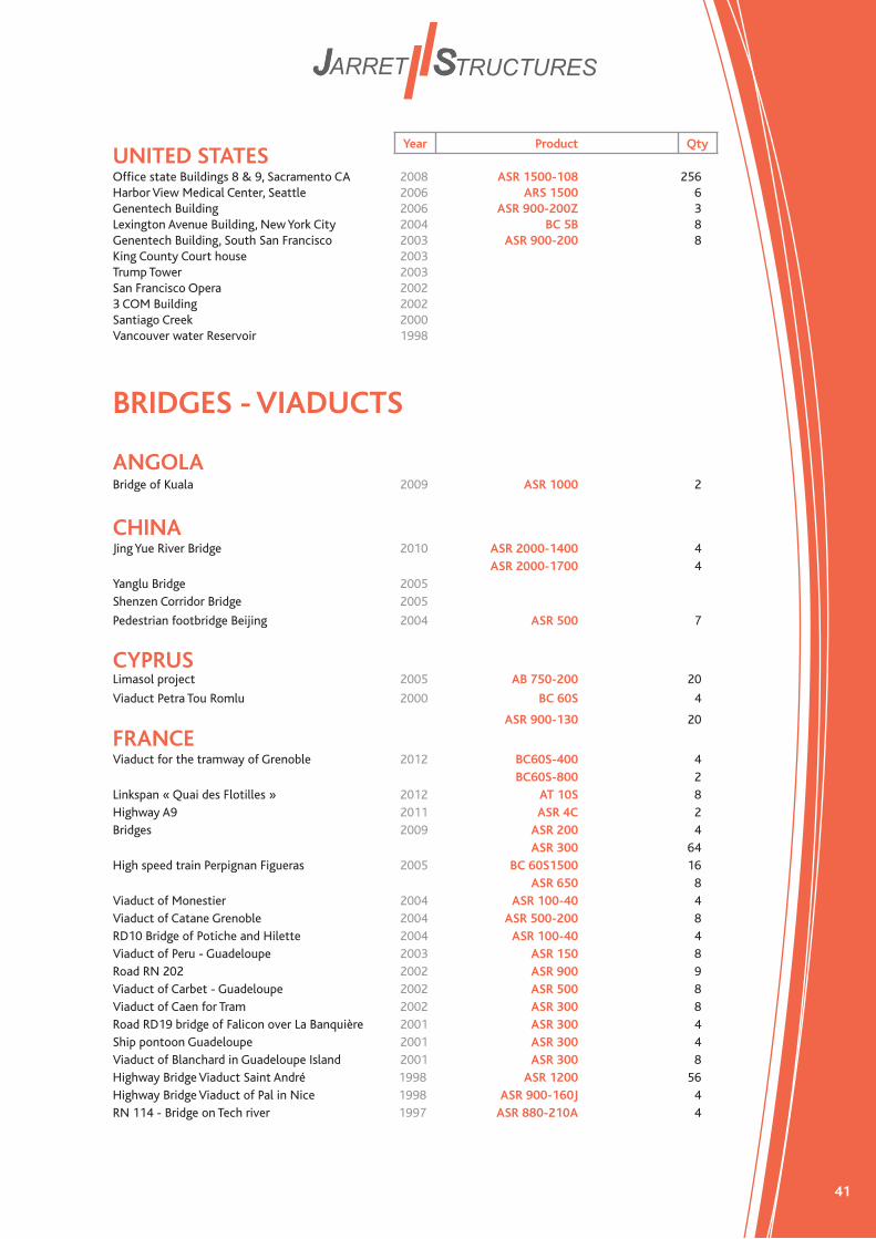
UNITED STATES Offi ce state Buildings 8 & 9, Sacramento CA 2008 ASR 1500-108 256Harbor View Medical Center, Seattle 2006 ARS 1500 6Genentech Building 2006 ASR 900-200Z 3 Lexington Avenue Building, New York City 2004 BC 5B 8Genentech Building, South San Francisco 2003 ASR 900-200 8King County Court house 2003Trump Tower 2003San Francisco Opera 20023 COM Building 2002Santiago Creek 2000Vancouver water Reservoir 1998
BRIDGES - VIADUCTS
ANGOLA Bridge of Kuala 2009 ASR 1000 2
CHINAJing Yue River Bridge 2010 ASR 2000-1400 4 ASR 2000-1700 4Yanglu Bridge 2005Shenzen Corridor Bridge 2005
Pedestrian footbridge Beijing 2004 ASR 500 7
CYPRUS Limasol project 2005 AB 750-200 20
Viaduct Petra Tou Romlu 2000 BC 60S 4
ASR 900-130 20
FRANCEViaduct for the tramway of Grenoble 2012 BC60S-400 4 BC60S-800 2Linkspan « Quai des Flotilles » 2012 AT 10S 8Highway A9 2011 ASR 4C 2Bridges 2009 ASR 200 4 ASR 300 64High speed train Perpignan Figueras 2005 BC 60S1500 16 ASR 650 8Viaduct of Monestier 2004 ASR 100-40 4Viaduct of Catane Grenoble 2004 ASR 500-200 8RD10 Bridge of Potiche and Hilette 2004 ASR 100-40 4Viaduct of Peru - Guadeloupe 2003 ASR 150 8Road RN 202 2002 ASR 900 9Viaduct of Carbet - Guadeloupe 2002 ASR 500 8Viaduct of Caen for Tram 2002 ASR 300 8Road RD19 bridge of Falicon over La Banquière 2001 ASR 300 4Ship pontoon Guadeloupe 2001 ASR 300 4Viaduct of Blanchard in Guadeloupe Island 2001 ASR 300 8Highway Bridge Viaduct Saint André 1998 ASR 1200 56Highway Bridge Viaduct of Pal in Nice 1998 ASR 900-160J 4RN 114 - Bridge on Tech river 1997 ASR 880-210A 4
Year Product Qty

42
BRIDGES - VIADUCTS
FRANCE (continuing)Railway Bridge TGV high speed train of Ventabren 1997 ASR 3000-650 8Highway A43 - Structure PS24 1996 ASR 500-100C 4Bridge PI14 1996 ASR 150-60C 8Bridge PS13 1996 ASR 300-80B 4Bridge PI09 1996 ASR 500-160D 8Bridge OH11 1996 ASR 500-100E 8Viaduct of Nantua 1995 ASR 300H 2Highway A51 - Plaine de la ReymureBridge d’Iroise Brest 1995 ASR 250-340A 8Highway A43 - Viaduct of Aiton 1995 ASR 500-260B 16HighwayA43 - Structure PS 3 1995 ASR 900-140A 4Viaduct for airport Raizet of Pointe à Pitre 1994 ASR 880-210A 28Viaduct of Reveston Perpignan 1990 ASR 50 4
Railway Bridge Busseau sur Creuse 1988 BC 10S150C 8
GREAT BRITAINBridge 2008 AB 1000 10Newark Dycke Bridge 1999 ACC 400-150 4Piff Elms Bridge 1998 ACC 300 4M5 Motor Way 1998 BC 1G 2
Baswich bridge railway bridge 1997 ACC 1100-160 8 BR 60S 2
GREECEBridge of Lionokladi-Domokos 25-52 km 2010 ASR 1500-400 4 ASR 3000-200 4 ASR 3000-400 8 ASR 1500-500 4 ASR 2000-500 2 ASR 1000-500 2 ASR 1000-500 4 ASR 3000-600 8 ASR 3000-300 6 ASR 3000-500 6Bridge of Domokos 0-14 km (SG 3, 5, 10 & 11) 2009 ASR 1500-350 8 ASR 1000-200 4 ASR 1500-350 34 ASR 1500-440 8 ASR 1500-160 8 ASR 1500-630 8Bridge of Domokos 14-28 km 2009 ASR 1000-250 8(SG12, 13, 14, 15 & 16) ASR 650-600 38 ASR 650-600 32 ASR 1000-300 16 ASR 650-300 38 ASR 650-700 12 ASR1000-200 4 ASR 650-250 8 ASR 650-900 4
INDONESIA Suramadu bridge Project 2008 ASR 1500-300 8Cikapayang Pasteur Bridge 2003 AB 3700-150 76
INDIA River Sone Bridge Bihiar 2002 AB 1200-150 16
Year Product Qty

43
ITALYViaduct of Meschio 1989 ATC 8Viaduct of Icla / Naples 1988 ATC 600 8Viaduct of Tagliamento 1988 ATC 8Bridge of Restello 1987 BC 80S 16Viaduct of San Cesaréo 1987 BC 80S 8Viaduct of Prenestino 1987 ATC 4Bridge Udine / Icop 1986 BC 80S 4
KAZAHKSTANBridge 2008 ASR 1000-300 2
LIBAN Viaducts Kaizarane 2001 ASR 300 20
MAROCCODam Al Waddah 1997 ACC 1750-150 4
PORTUGALBridge of Alto da Guerra Mitrena 2009 ASR 2000 8Viaduct of Sacavem 2008 ASR 120 120 ASR 650 30Bridge do Cuco 2008 ASR 1500 2Viaduct Ribeiro da Ponte 2005 ASR 1200 4Viaduct railway of Sintra 1998 ASR 250 2Viaduct of Colombo Lisbon 1997 ASR 900-240 9Viaduct of Luz Lisbon 1997 BC 10S600E 8Bridge on Douro Porto 1996 ASR 150-200A 12Bridge Vasco de Gamma on Tagus river Lisbon 1996 ASR 4000-700 10
SPAIN High speed railway Viaduct « Los Gallardos » 2012 ASR 1800-500 CE 16 ASR 1800-600 CE 8 ASR 1800-400 CE 4High speed railway Xativa Viaduct 2005 BC 60S1500-50 4High speed railway Viaduct Malaga 2004 ASR 1500-100 8High speed railway Rules Viaduct 2004 ASR 1500-600 12 BC 60S850-90 3High speed railway Viaduct 2001 AB 3000-100 4
TAIWAN Taiwan High speed train section 230 2002 AB 4500-100 32Taiwan High speed train Project section 220 2001 AB 4500-100 32
TURKMENISTANBridge 2011 ASR 3000 16 ASR 1500 58 ASR 3000 2
UNITED STATES Fred Hartmann Bridge, Houston 2003 ASR 140-300 176Coronado Bay Bridge 2001Vincent Thomas Bridge 1999Gerald Desmond Bridge 1997
Year Product Qty
44
ALBERT
PARIS
LONDRES
CALAIS
BRUXELLES
LUXEMBOURG
ROTTERDAM
ST QUENTIN
METZ
REIMS
STRASBOURG
FRANCFORT
HANOVRE
COLOGNE
LILLE
ROUEN
AMIENS
A13
A29-A28
A4
A4 A4
E50
E40
E30
E37
E45
E35
E40
A1
A16
A16
A1
E3 E10
E10
A26
A26
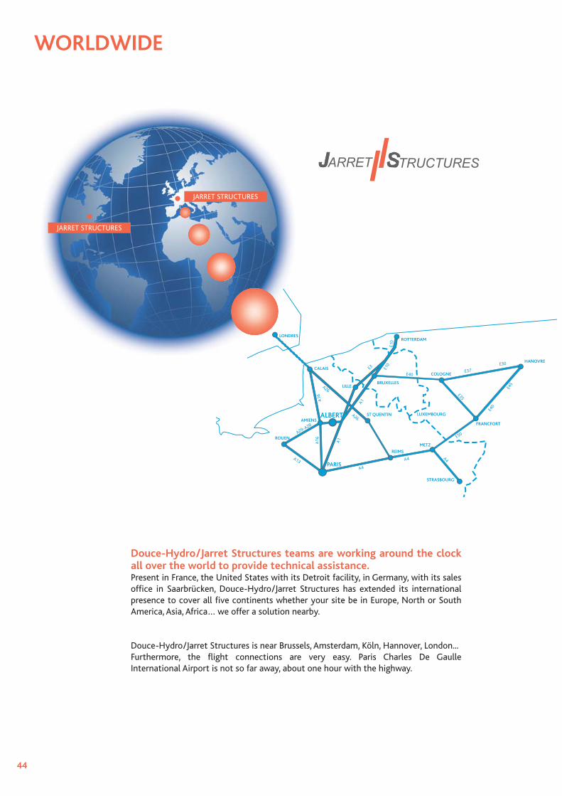
Douce-Hydro/Jarret Structures teams are working around the clock all over the world to provide technical assistance.Present in France, the United States with its Detroit facility, in Germany, with its sales offi ce in Saarbrücken, Douce-Hydro/Jarret Structures has extended its international presence to cover all fi ve continents whether your site be in Europe, North or South America, Asia, Africa… we offer a solution nearby.
Douce-Hydro/Jarret Structures is near Brussels, Amsterdam, Köln, Hannover, London...Furthermore, the fl ight connections are very easy. Paris Charles De Gaulle International Airport is not so far away, about one hour with the highway.
WORLDWIDE
JARRET STRUCTURES
JARRET STRUCTURES

45
D o u c e - H y d r o S A SD i v i s i o n J a r r e t S t r u c t u r e s Wo r l d w i d e H e a d q u a r t e r s2 rue de l'industrie - BP n° 2021380303 Albert cedex - FRANCETel. : + 33 (0)3 22 74 31 00Fax : + 33 (0)3 22 74 78 43www.doucehydro.comwww.jarretstructures.comExport : afl [email protected] [email protected]/Sales France : [email protected]
D o u c e - H y d r o I n cJ a r r e t S t r u c t u r e s I n cN o r t h A m e r i c a n H e a d q u a r t e r s
51151 CelesteShelby Township, MI 48315 - USATel. : + 1 (586) 566 47 25Fax : + 1 (212) 918 16 [email protected]@[email protected]@jarretstructures.comCommercial/Sales France : [email protected]

Douce-Hydro SASDivision Jarret Structures
2 rue de l’industrie - BP n° 2021380303 Albert cedex - FRANCE
Tél.: + 33 (0)3 22 74 31 00Fax: + 33 (0)3 22 74 78 43
Douce-Hydro Inc.Jarret Structures Inc.
51151 CelesteShelby Township, MI 48315 - USA
Tel.: + 1 (586) 566 47 25Fax: + 1 (212) 918 16 11
Websites: www.doucehydro.com - www.jarretstructures.com
Oct
ober
201
2