Embed Size (px)
Citation preview

Optimized Reflow Profiling to Minimize VoidingMB Allen, Product ManagerKIC

Outline
n Voiding – The Issuen The Causen Componentsn Challengesn Profiling as a solutionn Knowledge, tools and self-helpn Conclusion

Voiding – The Issuen Long time challenge – Voiding during reflow soldering
has been tormenting the industry for many years.
Increased challenges due to:n Lead-free assembliesn Miniaturization of componentsn Smaller & Larger, densely populated assembliesn Process Windown Reliability – Not covered in this sessionn Acceptability – Not covered in this session

‘Whether for power electronics, electronic aviation systems, medical equipment or electronic systems for the automotive industry, solder joint voids represent a significant problem. Enclosed voids can cause for displacement of electrical and thermal paths as well as local concentration of power and heat.”
Markus Walter, SehoSee ‘References 1’

The Cause
Voiding is attributed to the flux outgassing within the solder joints when the solder is at a molten state.
n Solder paste flux chemistry – Lead Freen Stenciln Placement
nProfile

Components
n BGAn CABGA, , LGA, MLFCBGA, PBGA,
CTBGA, CVBGA, DSBGA, FBGA, FCmBGA, LBGA, LFBGA, MBGA, MCM-PBGA, PBGA, SuperBGA, TABGA, TBGA, TEPBGA, TFGBA, UFBGA, UBGA, VFBGA, WFBGA
n CSPn QFN

Factors Affecting Voiding Reflow Soldering
See ‘References 2’

Challenges
1. Reduction/Elimination of voiding – How to2. PCB density and components3. Finding the right profile4. Change affects other components,
example: LED

The Art of Profiling
“.. the profiling process remains primarily as a art. Improvement in voiding control often comes out as results of extensive trial and error. Apparently, a fundamental understanding of the effect of the changing profile on voiding becomes critical for a prompt and efficient voiding reduction.” Dr. Yan Liu, Dr. Ning-Chen Lee et al, Indium Corp, reference ‘A Model Study of Profiling……………….” See ‘References 2’
“Profiling is the only real-time input variable that affects outcomes.” Tim O’Neil, AIM

Finding The Right Profile
n Soak
n RTP, RTS, Tent, Straight Ramp¨Lower Peak¨Higher Peak

Change Affects Other Components, example: LEDsn Balance reduction of voids with solder reliabilityn Must establish a profile for the entire assemblyn TC attachment on a cross of components¨ At leads¨ Under BTC¨ LED¨ Plastic connector¨ Capacitor/resistor
n Non-destructive profiling

Profiles
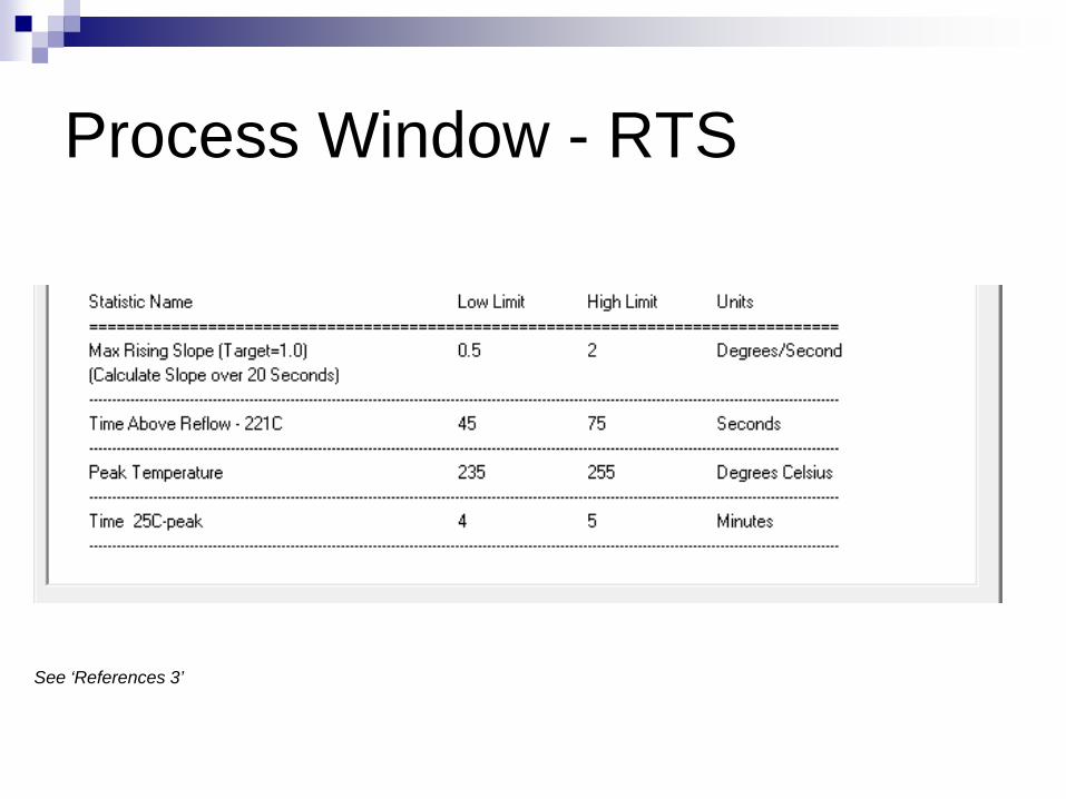
Process Window - RTS
See ‘References 3’

RTS
See ‘References 3’

Process Window – RTS Long TAL, High Peak
See ‘References 3’

RTS – Long TAL, High Peak
See ‘References 3’

Process Window Soak

Soak

Fine-tuning
n Finding the correct profile through oven parameter changes
n Optimizationn Separate Specifications By Thermocouple
Location, Location, Location¨BGA, QFN, BTC – Avoid voiding¨LED – Avoid sacrificing LEDs¨Plastic connectors – Avoid melting¨Chip/Resistors – Avoid over-heating

Profiling – Changes, Optimization +n Oven parameters¨ Setpoints¨ Belt Speed
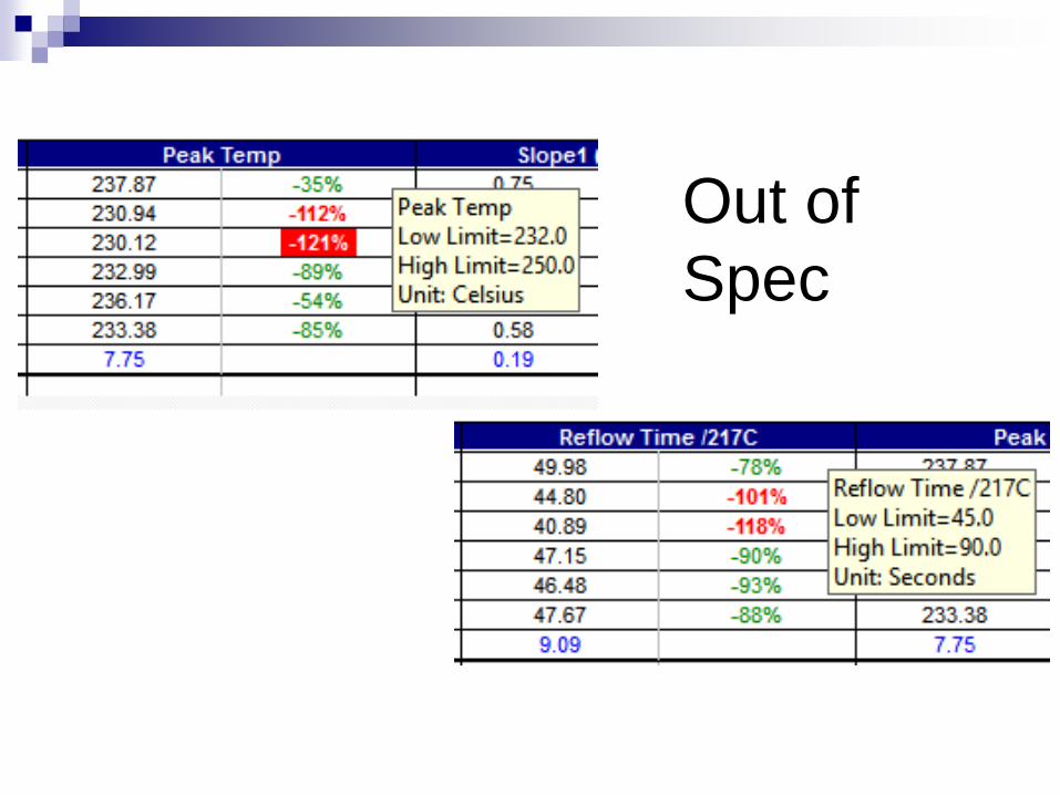
Out of Spec

Oven Changes
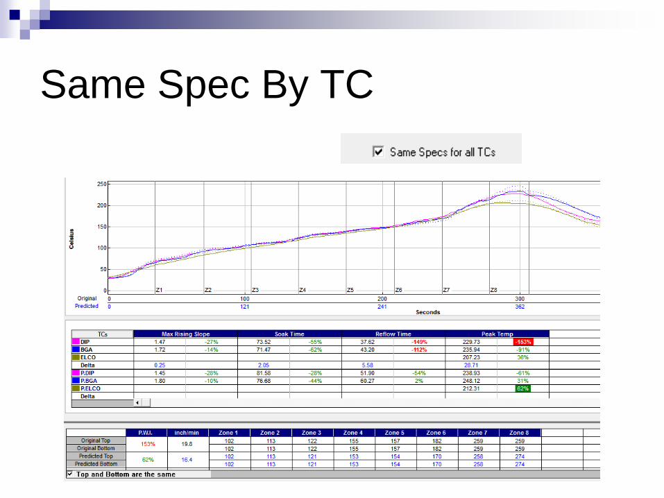
Same Spec By TC

Knowledge
n Know the specifications¨Solder Paste¨Components
n PCB layoutn Oven capabilities/limitations

Knowledgen Soak profiles are commonly used to help equalize temperatures across the circuit
board. Soak profiles are also recommended for certain solder pastes to drive off volatile materials and to fully clean and activate the metal surfaces. Extended soak times and/or high soak temperatures can cause pre-mature loss of activity in the solder paste resulting in wetting and solder balling issues.
n Linear ramp to spike profiles are also commonly used, and are typically a good starting place for most SMT processes. Linear ramp profiles provide enough time for the solder paste to activate and clean the metal surfaces while minimizing the risk of pre-mature loss of activity. The addition of a short soak can minimize the potential of defects like tombstoning. This needs to be done in a specific manner for each solder paste, because each solder paste responds differently to these type of profile changes.
Tony LentzFCT Assembly

Tools & Self-Help
n Profilern Software
n Historic data¨Problem assemblies¨Solutions¨Reference Documentation

Conclusionn Key focus to reduce/eliminate voiding is the reflow profilen Solder paste specifications are a guideline only
Excerpt from Aim Reflow Profile Supplement:“The information provided is a guideline only. Your profile will depend upon many factors including paste chemistry, customer requirements, component limitations, oven characteristics, board layout, etc. Ultimately, quality requirements should drive the process, not adherence to these guidelines.”
n Fine-tuning a profile for specific components limitations should be considered
n Include TCs on void-susceptible components when profilingn Balance TCs across components and PCB challengesn Use available tools to improve the time and accuracy of finding an optimum
profile

References
1) An interview with Markus Walter, CEO of Seho Systems GMBH. smttoday, November 2015 issue
2) A Model Study of Profiling for Voiding Control at lead-free Reflow Soldering, by Dr. Yan Liu, William Manning, Dr. Benlih Huang, Dr. Ning-Cheng Lee, Indium Corp.
3) Fill The Void by Tony Lentz & Greg Smith, FCT Assembly