Embed Size (px)
Citation preview
OPTIMIZATION OF MOLDING PARAMETER EFFECT TO WARPAGE OF CAR DASHBOARD BASED ON PLASTIC FLOW SIMULATION SOFTWARE
MOHD ZAHIRUDDIN BIN AZRI
Thesis submitted in fulfilment of the requirements for the award of the degree of
Bachelor of Mechanical Engineering with Automotive Engineering
Faculty of Mechanical EngineeringUNIVERSITI MALAYSIA PAHANG
NOVEMBER 2009
ii
SUPERVISOR DECLARATION
SUPERVISOR DECLARATION
I hereby declare that I have read this report and in my opinion this report is sufficient in term of scope and quality for the award of the degree of Bachelor of Mechanical Engineering with Manufacturing Engineering.
Signature : …………………………Name of Supervisor : MADAM SITI HARYANI BT TMADIPosition : Lecturer of Faculty Mechanical EngineeringDate : ………………………....

iii
STUDENT’S DECLARATION
I hereby declare that the work in this project is my own except for quotations and
summaries which have been duly acknowledged. The project has not been accepted for
any degree and is not concurrently submitted for award of other degree.
Signature: ..................................
Name: MOHD ZAHIRUDDIN BIN AZRI
ID Number: MH06069
Date: 20 NOVEMBER 2009

iv
DEDICATION
Another turning point,
A fork stuck in the road.
Time grabs you by the wrist,
Directs you where to go.
So make the best of this test,
And don't ask why.
It's not a question
But a lesson learned in time.
It's something unpredictable,
But in the end is right.
I hope you had the time of your life
Especially dedicated to
My beloved mother and father
v
ACKNOWLEDGEMENTS
First and foremost, I want to thank Allah S.W.T, for giving me the source of power, knowledge and strength to finish the project and dissertation for completing my Bachelor of Mechanical Engineering final year project. By gradually following the plan of optimization of molding parameter effect to warpage of car dashboard based on plastic flow simulation software, I’ve manage to fulfill my responsibility to this project.
I would like to express my gratitude to my supervisor Madam Siti Haryani Bt. Tomadi for her wisdom, endurance and encouragement during her supervision period. She motivates me about the importance of constant and gives me her outstanding professional conduct. I appreciate her consistent support from the first day I applied to graduate program to these concluding moments. I am truly grateful for her progressive vision about my training in science, his tolerance of my naive mistakes, and hercommitment to my future career. I also sincerely thanks for the time spent proofreading and correcting my many mistakes. I acknowledge my sincere indebtedness and gratitude to my parents for their love, dream and sacrifice throughout my life. My sincere thanks go to all my lab mates and members of the staff of the Mechanical Engineering Department, UMP, who helped me in many ways and made my stay at UMP pleasant and unforgettable. And also thanks to Dean Faculty of Mechanical Engineering, Associate Prof. Dr. Rosli Bin Abu Bakar for his advice and suggestion. I also sincerely thanks for the time spent proofreading and correcting my many mistakes.
I would also like to acknowledge with much appreciation the crucial role of the staff in Mechanical Laboratory, who gave a permission to use the computer laboratory to design and run the analysis and also the plastic laboratory to make mould measurement and to use all the necessary tools in the laboratory. Special thanks too goes to Mr. Azizuddin Bin Abd Aziz against as the Final Year Coordinator, who has give some advice and share his knowledge on this final year project.
Many thanks go to all the supervisors who have given their full effort in guiding the through on the project progress. I acknowledge my sincere indebtedness and gratitude to my parents for their love, dream and sacrifice throughout my life. Special thanks should be given to my committee members. I would like to acknowledge their comments and suggestions, which was crucial for the successful completion of this project.
vi
ABSTRACT
This thesis present about the optimization of molding parameter effect to warpage of car dashboard based on plastic flow simulation software. The objective of this project is to study, analyze, and optimize the parameters that effect to warpage with using plastic flow simulation software. This project using the manual measurement after the original method using 3D scanner cannot be done because of the technical report. The measurement uses the tools from the Faculty of Mechanical Engineering Laboratory such as ruler, vernier calliper, threads, and protractor. Then, draw the dashboard in SolidWork 2008. Using MoldFlow Plastics Insight (MPI) 5.0 software, the injection molding parameters are optimized to get the best parameters to minimize warpage. The small changes of molding parameters will give higher impact to the plastic characteristics. The comparison between the types of analysis will be made. The comparison is between the deflections, fill times, and volumetric shrinkage including air traps and weld lines. As the conclusion, the changes of molding parameters will affect the warpage of the car dashboard.
vii
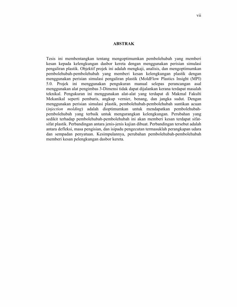
ABSTRAK
Tesis ini membentangkan tentang mengoptimumkan pembolehubah yang memberi kesan kepada kelengkungan dasbor kereta dengan menggunakan perisian simulasi pengaliran plastik. Objektif projek ini adalah mengkaji, analisis, dan mengoptimumkan pembolehubah-pembolehubah yang memberi kesan kelengkungan plastik dengan menggunakan perisian simulasi pengaliran plastik (MoldFlow Plastics Insight (MPI) 5.0. Projek ini menggunakan pengukuran manual selepas perancangan asal menggunakan alat pengimbas 3-Dimensi tidak dapat dijalankan kerana terdapat masalah teknikal. Pengukuran ini menggunakan alat-alat yang terdapat di Makmal Fakulti Mekanikal seperti pembaris, angkup vernier, benang, dan jangka sudut. Dengan menggunakan perisian simulasi plastik, pembolehubah-pembolehubah suntikan acuan (injection molding) adalah dioptimumkan untuk mendapatkan pembolehubah-pembolehubah yang terbaik untuk mengurangkan kelengkungan. Perubahan yang sedikit terhadap pembolehubah-pembolehubah ini akan memberi kesan terdapat sifat-sifat plastik. Perbandingan antara jenis-jenis kajian dibuat. Perbandingan tersebut adalah antara defleksi, masa pengisian, dan isipadu pengecutan termasuklah perangkapan udara dan sempadan penyatuan. Kesimpulannya, perubahan pembolehubah-pembolehubah memberi kesan pelengkungan dasbor kereta.
viii
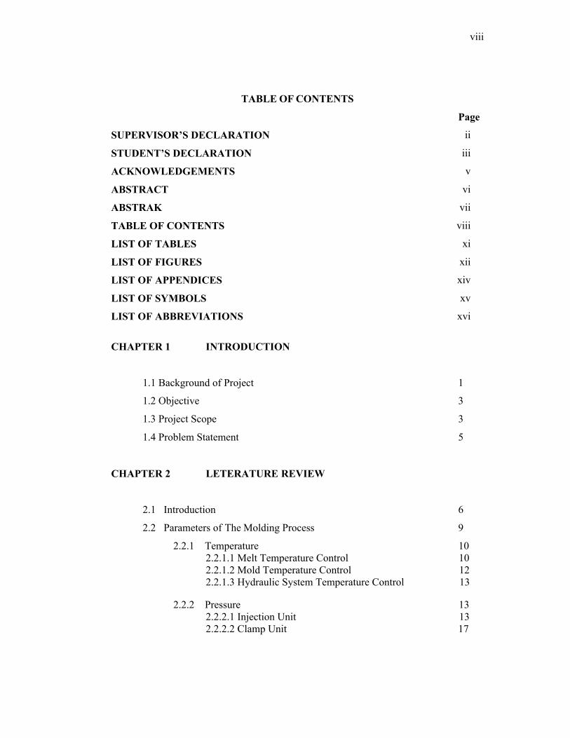
TABLE OF CONTENTS
Page
SUPERVISOR’S DECLARATION ii
STUDENT’S DECLARATION iii
ACKNOWLEDGEMENTS v
ABSTRACT vi
ABSTRAK vii
TABLE OF CONTENTS viii
LIST OF TABLES xi
LIST OF FIGURES xii
LIST OF APPENDICES xiv
LIST OF SYMBOLS xv
LIST OF ABBREVIATIONS xvi
CHAPTER 1 INTRODUCTION
1.1 Background of Project 1
1.2 Objective 3
1.3 Project Scope 3
1.4 Problem Statement 5
CHAPTER 2 LETERATURE REVIEW
2.1 Introduction 6
2.2 Parameters of The Molding Process 9
2.2.1 Temperature 102.2.1.1 Melt Temperature Control 102.2.1.2 Mold Temperature Control 122.2.1.3 Hydraulic System Temperature Control 13
2.2.2 Pressure 132.2.2.1 Injection Unit 132.2.2.2 Clamp Unit 17
ix
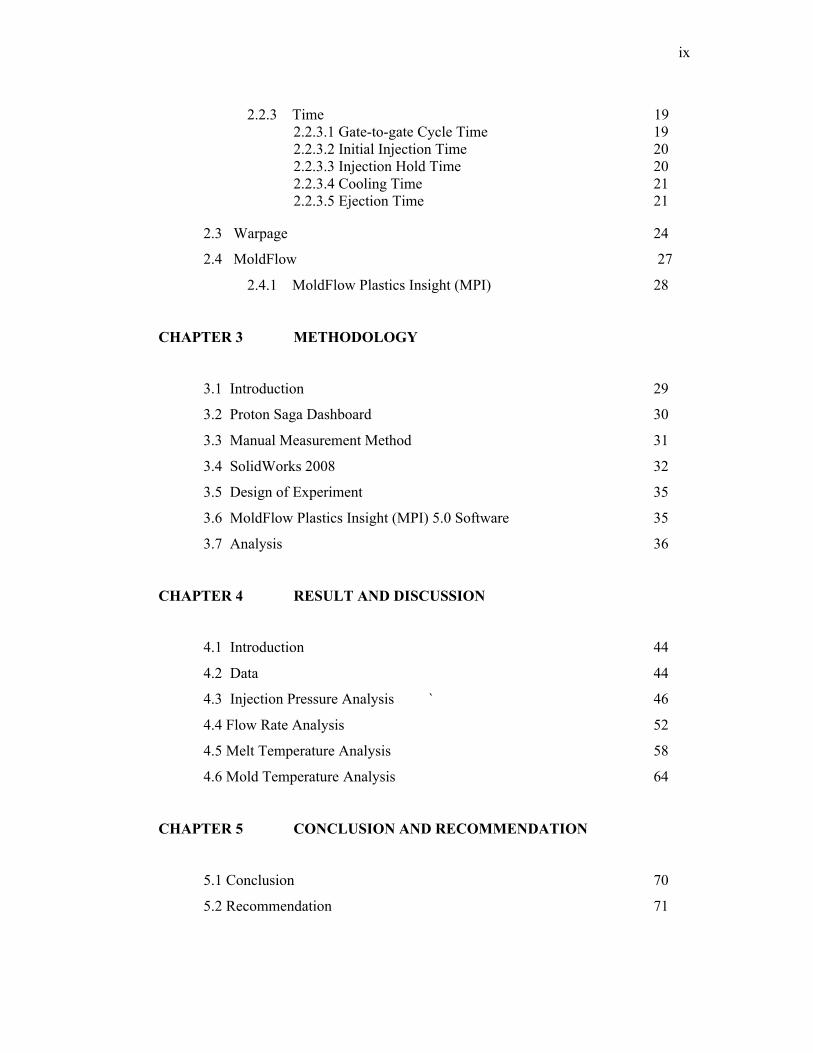
2.2.3 Time 192.2.3.1 Gate-to-gate Cycle Time 192.2.3.2 Initial Injection Time 202.2.3.3 Injection Hold Time 202.2.3.4 Cooling Time 212.2.3.5 Ejection Time 21
2.3 Warpage 24
2.4 MoldFlow 27
2.4.1 MoldFlow Plastics Insight (MPI) 28
CHAPTER 3 METHODOLOGY
3.1 Introduction 29
3.2 Proton Saga Dashboard 30
3.3 Manual Measurement Method 31
3.4 SolidWorks 2008 32
3.5 Design of Experiment 35
3.6 MoldFlow Plastics Insight (MPI) 5.0 Software 35
3.7 Analysis 36
CHAPTER 4 RESULT AND DISCUSSION
4.1 Introduction 44
4.2 Data 44
4.3 Injection Pressure Analysis ` 46
4.4 Flow Rate Analysis 52
4.5 Melt Temperature Analysis 58
4.6 Mold Temperature Analysis 64
CHAPTER 5 CONCLUSION AND RECOMMENDATION
5.1 Conclusion 70
5.2 Recommendation 71

x
REFERENCES 72
APPENDICES 75
xi
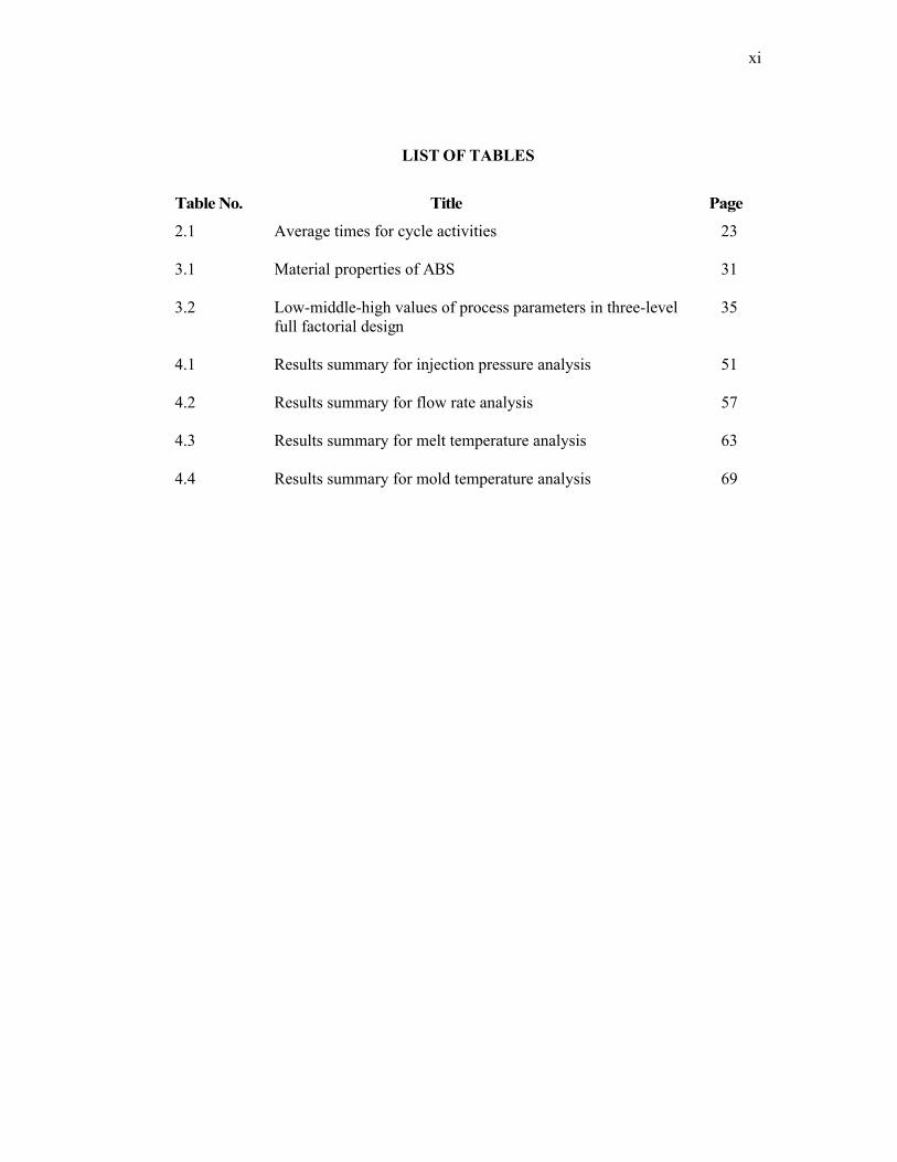
LIST OF TABLES
Table No. Title Page
2.1 Average times for cycle activities 23
3.1 Material properties of ABS 31
3.2 Low-middle-high values of process parameters in three-level 35 full factorial design
4.1 Results summary for injection pressure analysis 51
4.2 Results summary for flow rate analysis 57
4.3 Results summary for melt temperature analysis 63
4.4 Results summary for mold temperature analysis 69
xii
LIST OF FIGURES
Figure No. Title Page
2.1 Main processing parameters 10
2.2 Heating cylinder (barrel) 11
2.3 Developing injection pressure 14
2.4 Applying holding pressure 15
2.5 Applying back pressure 16
2.6 Types of shrinkage 26
3.1 Proton saga dashboard 30
3.2 Isometric view of Proton Saga Dashboard 32
3.3 Front view of Proton Saga Dashboard 33
3.4 Top view of Proton Saga Dashboard 33
3.5 Side view of Proton Saga Dashboard 34
3.6 Create new project 36
3.7 Import ‘iges’ file from CAD drawing 37
3.8 Generate the meshing entity 37
3.9 Mesh pattern appeared on Saga Dashboard (fusion) 38
3.10 Analysis sequence wizard (flow + warp analysis) 38
3.11 Toyolac 100 fom ABS family have been chosen 39
3.12 Gate location 39
3.13 Runner and gate system to set up 40
3.14 Runner and gate system be done 40
3.15 Cooling system type setup 41
3.16 Complete modelling with cooling and runner system 41
xiii
3.17 Process parameter setup 42
3.18 Perform the analysis 42
3.19 Flow chart 43
4.1 Car dashboard in MoldFlow Plastics Insight 5.0 44
4.2 Fill time for different injection pressure 46
4.3 Air traps for different injection pressure 47
4.4 Weld lines for different injection pressure 48
4.5 Deflections for different injection pressure 49
4.6 Volumetric shrinkage for different injection pressure 50
4.7 Fill time for different flow rate 52
4.8 Air traps for different flow rate 53
4.9 Weld line for different flow rate 54
4.10 Deflection for different flow rate 55
4.11 Volumetric shrinkage for different flow rate 56
4.12 Fill time for different melt temperature 58
4.13 Air trap for different melt temperature 59
4.14 Weld line for different melt temperature 60
4.15 Deflection for different melt temperature 61
4.16 Volumetric shrinkage for different melt temperature 62
4.17 Fill time for different mold temperature 64
4.18 Air trap for different mold temperature 65
4.19 Weld line for different mold temperature 66
4.20 Deflection for different mold temperature 67
4.21 Volumetric shrinkage for different mold temperature 68
xiv
LIST OF APPENDICES
Appendix Title Page
A 1 Gantt Chart For Final Year Project (FYP) 1 75 A2 Gantt Chart For Final Year Project (FYP) 2 76
B1 Dashboard Drawing 77
B2 Front View of Design 78
B3 Top View of Design 79
B4 Right View of Design 80
C MoldFlow Analysis Results 81
xv
LIST OF SYMBOLS
0C Degree Celsius
% Percent
MPa Mega Pascal
cm3/s Centimeter cubic per second
xvi
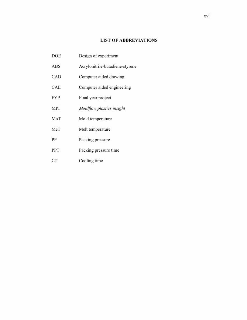
LIST OF ABBREVIATIONS
DOE Design of experiment
ABS Acrylonitrile-butadiene-styrene
CAD Computer aided drawing
CAE Computer aided engineering
FYP Final year project
MPI Moldflow plastics insight
MoT Mold temperature
MeT Melt temperature
PP Packing pressure
PPT Packing pressure time
CT Cooling time
1
CHAPTER 1
INTRODUCTION
The sole purpose of this project is to optimize molding parameter effect to
warpage of car dashboard based on plastic flow simulation software. The basic
perspective of this project is injection molding. The definition of this word is shape-
forming process in which molten metal or plastic is injected into aluminum, ceramic, or
steel molds (shaped like the end product) and squeezed under high pressure. Injection
molding is employed mainly in the production of solid objects.
Therefore, as a student of mechanical engineering of University Malaysia
Pahang, this project exposes student the field of manufacturing engineering as part of
mechanical engineering. The optimization of molding parameter is the first step to make
product better.
1.1 BACKGROUND OF PROJECT
There are several steps to finish this project. Firstly, focus on injection molding
process. Injection molding is the molten plastic is injected into the mold cavity to form
shape with high pressure and high temperature and hold it there until the parts are cool
and stiff enough to be removed from the die.
The second step is molding parameters. In this case study, focus on four (4)
molding parameters that needed in the injection molding. There are flow rate, injection
pressure, mold temperature, and melt temperature. These molding parameters will give
effect to the plastic depend on how it will be control. So, the small changes of molding
parameters will give significant impact to the plastic characteristics.
2
Warpage is a distortion where the surfaces of the molded part do not follow the
intended shape of the design. Warpage relates to the distortion induced by the
inhomogeneous shrinkage and relaxation of residual stress in the part once outside the
mold, shrinkage expresses the overall dimensional change as the unconstrained part
cool down to ambient temperature. [1-4]
There are many molding parameters effect to warpage such as mold cooling,
part and mold designs, and process conditions, injection pressure, back pressure, melt
temperature and mold temperature. In this case study, the molding parameters that
considered are stated before; flow rate, injection pressure, mold temperature, and melt
temperature. All these parameters must be calculated to get the best plastic with lowest
warpage compare than before.
In this case study, the needed is optimizing molding parameter effect to warpage
of car dashboard based on plastic flow simulation software and reverse engineering
method. Reverse engineering means that the process of duplicating an existing part,
subassembly, or product, without drawings, documentation, or a computer model. It
also defined as the process of discovering the technological principles of a device,
object or system through analysis of its structure, function and operation. It often
involves taking something apart and analyzing its workings in detail, used in
maintenance or to try to make a new device or program that does the same thing without
copying anything from the original. It’s used to make car dashboard more stable in
contain, strength, and brittle with minimum failure. [13, 14]
3
1.2 OBJECTIVES
The objectives of this case study are to:
1. Study the parameters effect in injection molding to car dashboard
2. Analyze the effect of molding parameters such as melt flow rate, injection
pressure, mould temperature and melt temperature to warpage of car dashboard.
3. Optimize the molding parameters by using plastic flow simulation software in
order to get a good result.
1.3 PROJECT SCOPES
To start of this project, a thoroughly research of review is done with the means
of the internet, books, available published articles and materials that related to the title
and supervisor’s guidance. This is a continuing progress until sufficient knowledge is
attained to complete the project.
The original idea of this project is using the reverse engineering in 3D scanning
existing product in laboratory which is car dashboard. Unfortunately, the 3D scanner in
the Faculty of Mechanical Laboratory cannot be used because of the technical problem.
Due to that problem, this project changed to the manual measurement method.
Next is modeling the product in design software. For this project, the software
called SolidWorks is chosen. SolidWorks is a 3D mechanical CAD (computer-aided
design) program that runs on Microsoft Windows and was developed by SolidWorks
Corporation. The reason using this software are solid-based solid modeler, utilizes a
parametric feature-based approach to create models and assemblies. [8, 9]
Here, parameters refer to constraints whose values determine the shape or
geometry of the car dashboard. Numeric parameters can be associated with each other
through the use of relations, which allow them to capture design intent. Building a
model in SolidWorks usually starts with a 2D sketch. The sketch consists of geometry
such as points, lines, arcs, conics, and splines. Dimensions are added to the sketch to
4
define the size and location of the geometry. Relations are used to define attributes such
as tangency, parallelism, perpendicularity, and concentricity. The parametric nature of
SolidWorks means that the dimensions and relations drive the geometry, not the other
way around. The dimensions in the sketch can be controlled independently, or by
relationships to other parameters inside or outside of the sketch. [8, 9]
After do the car dashboard shape and it will analyze by using plastic flow
software. The flow analysis software can predict the flow of plastic throughout the
injection molding cycle to ensure that acceptable parts are designed for the manufacture.
Using flow analysis, the optimizing gate locations and processing conditions assess
possible part defects, and automatically determine the dimensions for a balanced feed
system by considering the low effects resulting from differential mold-block
temperatures and asymmetries in part geometry. One can also determine the optimum
set-up for polymer valve gate timing sequences and determine whether hot or cold
runners are appropriate.
Then optimize using mold flow software. Once the plastics injection and
packing phases have been optimized, cooling circuits and a mold block- including mold
inserts- can be modeled around a part for a mold cooling analysis. The mold design can
be optimized by adjusting the size and locations of cooling circuits, as well as
modifying circuit and coolant processing parameters. All the benefits of mold cooling
analysis can be applied to gas injection molded parts as well.
Finally the molding process optimization can be done by using proper method
and processing condition. Thus, the molding process will produce better product in a
process.
5
1.4 PROBLEM STATEMENT
From research that have been done, determine optimal process parameter
settings critically influence productivity, quality, and cost of production in the plastic
injection molding industry. Previously, production engineers used trial-and-error
method to determine optimal process parameter setting for plastic injection molding.
However, this method is unsuitable in present plastic injection molding because the
increasing complexity of product design and the requirement of multi-response quality
characteristics. This research presents an approach in plastic flow software for the
optimization of the parameters effect to the car dashboard.
In this project, what is needed is to use the plastic flow simulation software. This
software includes all the information that needed in optimizing the warpage of car
dashboard. After get the best result, the values of the parameters are applied to
production line using injection molding. All these thing are very important to make sure
that product can have long life time depends on its strength, capability working with
higher temperature and vibration.
6
CHAPTER 2
LITERATURE REVIEW
2.1 INTRODUCTION
For the injection molding cycle to begin, four criteria must be met: mold open,
ejector pins retracted, shot built, and carriage forward. When these criteria are met, the
cycle begins with the mold closing. This is typically done as fast as possible with a slow
down near the end of travel. Mold safety is low speed and low pressure mold closing. It
usually begins just before the leader pins of the mold and must be set properly to
prevent accidental mold damage. When the mold halves touch clamp tonnage is built.
Next, molten plastic material is injected into the mold. The material travels into the
mold via the sprue bushing, and then the runner system delivers the material to the gate.
The gate directs the material into the mold cavity to form the desired part. This injection
usually occurs under velocity control.
When the part is nearly full, injection control is switched from velocity control
to pressure control. This is referred to as the pack/hold phase of the cycle. Pressure must
be maintained on the material until the gate solidifies to prevent material from flowing
back out of the cavity. Cooling time is dependent primarily on the wall thickness of the
part but also depends on the material being molded. Production molding usually
requires faster cooling. Water is often channeled throughout the dies to produce faster
cooling times. During the cooling portion of the cycle after the gate has solidified,
plastication takes place.
7
Plastication is the process of melting material and preparing the next shot. The
material begins in the hopper and enters the barrel through the feed throat. The feed
throat must be cooled to prevent plastic pellets from fusing together from the barrel
heat. The barrel contains a screw that primarily uses shear to melt the pellets and
consists of three sections. The first section is the feed section which conveys the pellets
forward and allows barrel heat to soften the pellets. The flight depth is uniform and
deepest in this section. The next section is the transition section and is responsible for
melting the material through shear. The flight depth continuously decreases in this
section, compressing the material. The final section is the metering section which
features a shallow flight depth, improves the melt quality and color dispersion. At the
front of the screw is the non-return valve which allows the screw to act as both an
extruder and a plunger. When the screw is moving backwards to build a shot, the non-
return assembly allows material to flow in front of the screw creating a melt pool or
shot. During injection, the non-return assembly prevents the shot from flowing back
into the screw sections.
Once the shot has been built and the cooling time has timed out, the mold opens.
Mold opening must occur slow-fast-slow. The mold must be opened slowly to release
the vacuum that is caused by the injection molding process and prevent the part from
staying on the stationary mold half. This is undesirable because the ejection system is
on the moving mold half. Then the mold is opened as far as needed, if robots are not
being used, the mold only has to open far enough for the part to be removed. A
slowdown near the end of travel must be utilized to compensate for the momentum of
the mold. Without slowing down the machine cannot maintain accurate positions and
may slam to a stop damaging the machine. Once the mold is open, the ejector pins are
moved forward, ejecting the part. When the ejector pins retract, all criteria for a molding
cycle have been met and the next cycle can begin.[11]
The basic injection cycle is as follows: Mold close – injection carriage forward – inject
plastic – metering – carriage retract – mold open – eject part(s) Some machines are run
by electric motors instead of hydraulics or a combination of both. The water-cooling
channels that assist in cooling the mold and the heated plastic solidifies into the part.
8
Improper cooling can result in distorted molding. The cycle is completed when the mold
opens and the part is ejected with the assistance of ejector pins within the mold.
The raw material for injection molding is most commonly supplied in pellet or
granule form. Pellets are poured into the feed hopper, a large open bottomed container,
which is attached to the back end of a cylindrical, horizontal barrel. A screw within this
barrel is rotated by a motor, feeding pellets up the screw's grooves. The depth of the
screw flights decreases toward the end of the screw nearest the mold, compressing the
heated plastic. As the screw rotates, the pellets are moved forward in the screw and they
undergo extreme pressure and friction which generates most of the heat needed to melt
the pellets. Electric heater bands attached to the outside of the barrel assist in the heating
and temperature control during the melting process.
The channels through which the plastic flows toward the chamber will also
solidify, forming an attached frame. This frame is composed of the sprue, which is the
main channel from the reservoir of molten resin, parallel with the direction of draw, and
runners, which are perpendicular to the direction of draw, and are used to convey
molten resin to the gate(s), or point(s) of injection. The sprue and runner system can be
cut or twisted off and recycled, sometimes being granulated next to the mold machine.
Some molds are designed so that the part is automatically stripped through action of the
mold.
Optimizing the parameters for injection molding will ensure quality products,
with minimum of molded-in-stress, at lower manufacturing cost. All parameter
adjustment will have an effect (positive or negative) on the physical and aesthetic
properties of the molded product. Understanding this relationship allows the molder to
manipulate the properties to meet specific requirement establish for the product.