Embed Size (px)
Citation preview

Optimization of high-performance monocentric lenses
Igor Stamenov,* Ilya Agurok, and Joseph E. FordDepartment of Electrical and Computer Engineering, University of California San Diego,
9500 Gilman Drive, La Jolla, California 92093-0409, USA
*Corresponding author: [email protected]
Received 23 September 2013; accepted 15 October 2013;posted 28 October 2013 (Doc. ID 198070); published 25 November 2013
The recent application of monocentric lenses for panoramic high-resolution digital imagers raises thequestion of the achievable performance limits of this lens structure and of techniques for designoptimization to approach these limits. This paper defines the important regions of the design spaceof moderate complexity monocentric lenses and describes systematic and global optimization algorithmsfor the design of monocentric objective lenses of various focal lengths, apertures, and spectral band-widths. We demonstrate the trade-off between spectral band, F-number and lens complexity, and providedesign examples of monocentric lenses for specific applications. © 2013 Optical Society of AmericaOCIS codes: (080.3620) Lens system design; (110.0110) Imaging systems; (220.4830) Systems
design.http://dx.doi.org/10.1364/AO.52.008287
1. Introduction
Monocentric imaging lenses, which are constrained tohave only spherical surfaces centered on a single pointof symmetry, can produce a high-resolution image on aspherical image surface. Since high-resolution spheri-cal detectors are not currently available, in practicalapplication this image surface is optically transferredonto multiple conventional focal planes. This can bedone by relay through multiple adjacent sets of secon-dary optics, as in monocentric multiscale imagers[1,–3]. Alternately, it can be done via imaging fiberbundles with curved input and flat output faces, asin the monocentric fiber-coupled imagers [4–9]. Thesesuccessful demonstrations motivate a more system-atic exploration of the capabilities of the monocentricimaging lens.
In a lens with centered spherical or hemisphericalsurfaces, off-axis aberrations of coma and astigma-tism are cancelled [10], but we need to correct spheri-cal and chromatic aberration and their combinationspherochromatism. Reducing spherochromatism isdifficult, especially with large apertures. But despite
the monocentric constraint, and even with a smallnumber of degrees of freedom, it is possible to obtaina number of useful designs [3,4,8,11].
In a previous paper [8], we reported the generalaberration analysis of two-glass symmetric (2GS)monocentric lenses and results of our 2GS globalsearch algorithm applied for a specific example, a12 mm focal length, F/1.7, 120° field of view lensoperating in 470–650 nm visible waveband. The al-gorithm described identified the optimum diffractionlimited design [Fig. 1(a)] and a number of additionalfamilies of high-performing solutions. However, if wesubstantially increase the lens spectrum, light collec-tion, or the scale, even after repeated 2GS globalsearch, we will not achieve desired performance[Figs. 1(b)–1(d)]. The 2GS monocentric architecturereaches its limits.
Achieving a similar level of performance withthese extended operating specifications demandsmore complex monocentric lens architectures, withmore degrees of freedom. This is especially true whenincreasing more than one of these performance met-rics. In this paper, we show methods and algorithmsfor advanced monocentric lens design. We categorizethe monocentric lens design space, provide proce-dures for optimum and near-optimum lens design
1559-128X/13/348287-18$15.00/0© 2013 Optical Society of America
1 December 2013 / Vol. 52, No. 34 / APPLIED OPTICS 8287

with complexity and performance trade-off consider-ations, and in Section 5 provide specific lens designsfor selected applications.
2. Options for Improving Monocentric Lenses
A. Review of Monocentric Lens Architectures
The simplest monocentric lens architecture is a sim-ple glass ball [12,13] with inset aperture stop. Histor-ically, the more common approach was an achromatic2GS architecture, used by Sutton in 1856, Baker in1942 [14], and more recently by Brady and co-work-ers [1,3] and Ford and co-workers [2,15]. A more com-plex three-glass symmetric structure (3GS) withthird-order aberration analysis was designed andfabricated by Oakley [16] for a panoramic sphericalretroreflector. However, high order aberrations atlarge apertures were not systematically corrected.
Our goal was to push the performance of theexisting lens and identify the limit of what monocen-tric lenses can or cannot do. We started by usingcommercial lens design software to explore the mono-centric lens design space by a systematic increase ofdegrees of freedom in the system, while maintainingthe monocentricity constraint, to identify the majorconfigurations, which showed the most promise. Weconstrained the focal length and did a lens optimiza-tion for all options with a given number of degrees offreedom (i.e., glass choice, surface radius) and com-pared performance to the diffraction limit. Glass asan optical material has at least two descriptionparameters, the index of refraction, and the Abbenumber. To model the dispersion over a broader spec-tral range would require an expression with evenmore free parameters. But since we don’t have theability to create a glass with arbitrary index anddispersion, the choice of an existing glass materialrepresents only a single degree of freedom. We usetheir accurate models described by Sellmeier,Extended, or Schott glass model formulas.
Figure 2 summarizes the result, showing 100different geometries and the seven preferred design
architectures (drawn with a larger scale). Thosepreferred architectures were labeled as
1GS: One-glass symmetric with 1 degree of free-dom (DOF)2GS: Two-glass symmetric with 3 DOF3GS: Three-glass symmetric with 5 DOF3GA-7: Three-glass asymmetric with air gapand 7 DOF4GA-8: Four-glass asymmetric with air gap and8 DOF4GA-9: Four-glass asymmetric with air gap and9 DOF5GA-10: Five-glass asymmetric with air gap and10 DOF.
The 1GS, 2GS, 3GS, and 4GA-8 geometries werechosen for rigorous analysis and investigation, be-cause they offered the best performance for theirstructural complexity.
The simplest 1GS geometry is a symmetric glassball, with only one degree of freedom (1 DOF). When
Fig. 1. MTF performance curves showing the limits of the globally optimized 2GS monocentric geometries. The examples are derivedfrom an initial high-performing lens (a), which is pushed to improve spectral bandwidth (b), numerical aperture (c), or focal length (d)[using a 3× scale change to the illustration]. For each, the resolution of the two-glass structure drops well below the diffraction limit,indicating a need for greater complexity.
Fig. 2. Monocentric lens design space showing glass only(upper half) and glass with air gap (lower half) regions dividedby the seven preferred design architectures in between.
8288 APPLIED OPTICS / Vol. 52, No. 34 / 1 December 2013

the desired monocentric system is being designed,focal-length input constrains one of the radii, sothe choice of glass in this structure remains asthe single variable. Since there is no chromatismcorrection, this architecture is suitable mostly formonochromatic imagers with a relatively largeF-number. In air, if we allow this geometry to becomeasymmetric, or increase degrees of freedom to two,the optimizer will converge back to the original1GS structure as depicted in the upper half of Fig. 2.A similar outcome results if we introduce an air gapand push up to the maximum of six degrees of free-dom (lower part of Fig. 2).
The next logical step was to make the achromaticlens with an additional glass, which yields the 2GSgeometry with three degrees of freedom. As in 1GSgeometry, optimization after lens splitting and intro-ducing an air gap will converge back to the simpler2GS geometry, while taking the upper “glass modifi-cation only” path on the chart by allowing all radii tovary will land in a 5DOF two-glass architecture thatperforms substantially the same as the simplest 2GSstructure.
Adding the third and fourth glass in the monocen-tric structure and breaking the symmetry goes deepinto the upper “glass modification only” region of thedesign space and offers only marginal improvementover 2GS and 3GS structures, not justifying the costof manufacture. Therefore, simple symmetry break-ing and glass adding is not productive. The upperhalf of the diagram is only partially populated—ifwe allow more glasses and more degrees of freedom,architecture will essentially converge to somevariant of the Luneburg lens solution [17].
On the other hand, starting from 5DOF structurewith three glasses and introducing an air gap alsodoesn’t appear to help, as we continue along the lowerpart of Fig. 2 (glass with air gap path) up to the 6thdegree of freedom. Then just a simple step over tothe 7 degrees of freedom 3GA-7 architecture gives asubstantial increase in performance, as shown withred arrow in Fig. 2. Further derivatives 4GA-8,4GA-9, and 5GA-10 just keep up with the sametrend. Out of these asymmetric structures with anair gap, 4GA-8 is the most attractive one to pursuewith an addition of 5GA-10 for larger scale lenseswhere the maximum glass slab size plays an impor-tant role.
Looking at this comprehensive monocentric lensdesign space chart, an interesting fact is that simplyadding the degrees of freedom at some point does nothelp. This is somewhat counter-intuitive. For thetwo, four, and six degrees of freedom cases, no pre-ferred monocentric lens structure exists. All sym-metry breaking attempts in this ≤6 DOF areainevitably converge back to the symmetric structureswhen the lens is designed for the use in air. A slightchange to this rule applies only when the lens has adifferent medium in object and image space (e.g., animmersed lens), where a 4 DOF two-glass structurewith symmetric core becomes the preferred design.
Our next goal was to find specific high-performance designs. To do this we developed globalsearch algorithms for symmetric geometries, andsystematic search methods for the asymmetric geom-etries with an air gap, as described in the following.
B. Review of Monocentric Lens Design Methods
Throughout the exploration of monocentric lens de-sign space, several methods and optimization algo-rithms were developed. In previous work [8], wepresented a global optimization algorithm for the2GS architecture. Now a similar approach was usedin one-glass (1GS) and three-glass (3GS) symmetricarchitectures, and a similar global search algorithmwas developed. Since all these global optimizationroutines are essentially brute force calculations(for all possible glass combinations), with further in-crease in the number of degrees of freedom the cost ofcomputing became prohibitive. Therefore, we devel-oped systematic search methods. All the methods usespectral band, focal length, and F-number as an in-put for the desired system, and a predefined pool ofcommercially available glasses. These included theSchott, Ohara, Hoya, Sumita catalogs as well asCAF2 and fused silica, totaling 604 different materi-als available as of April 2013. Hikari, CDGM, andNHG manufacturers were not used because almostall of their glasses represent duplicate replacementsof the glasses already included.
The optimization methods used, in order of in-creasing complexity and computation time, were
• 1GS global optimization algorithm (seconds tocomplete)• 2GS global optimization algorithm (minutes
to complete)• 3GS global optimization algorithm (days to
complete)• 2GS seeded Hammer search (hours to days)• 4GA-8 architecture 5-D “near global” search
(up to 3 weeks).
Preliminary results of these methods were pre-sented in [18] but will be described in more detailhere. Global optimization algorithms for 1GS, 2GS,and 3GS architectures are multithreaded exact raytrace routines implemented in MATLAB. These checkall possible glass choices (604 for 1GS, 364,816 for2GS, and more than 220 million combinations for3GS geometry). They were executed on PC worksta-tions with two Intel 3.1 GHz Xeon E5-2687 W or fourIntel 2.7 GHz Xeon E5-4650 Sandy Bridge based pro-cessors (16∕32 CPU cores systems). The 3GS globaloptimization algorithm was also rewritten and testedon Kepler based NVIDIA K20 Tesla and K5000Quadro GPU cards, with speed improvements onthe order of 70×, effectively cutting down the comput-ing time required from days to hours.
The 2GS seeded Hammer search approach usedglass combinations of the top 2GS candidates ob-tained through global search, then imported in
1 December 2013 / Vol. 52, No. 34 / APPLIED OPTICS 8289
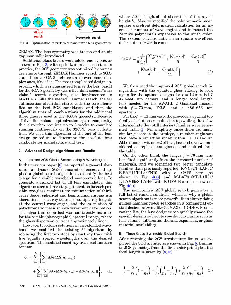
ZEMAX. The lens symmetry was broken and an airgap manually introduced.
Additional glass layers were added one by one, asshown in Fig. 3, with optimization at each step. Inpractice, the 2GS geometry was optimized by humanassistance through ZEMAX Hammer search to 3GA-7 and then to 4GA-8 architecture or even more com-plex ones, if needed. The most complicated design ap-proach, which was guaranteed to give the best resultfor the 4GA-8 geometry, was a five-dimensional “nearglobal” search algorithm, also implemented inMATLAB. Like the seeded Hammer search, the 5Doptimization algorithm starts with the core identi-fied as the best 2GS candidates, and then thealgorithm tries all combinations for the additionalthree glasses used in the 4GA-8 geometry. Becauseof five-dimensional optimization space complexity,this algorithm requires up to 3 weeks to completerunning continuously on the 32CPU core worksta-tion. We used this algorithm at the end of the lensdesign procedure to determine the absolute bestcandidate for manufacture and test.
3. Advanced Design Algorithms and Results
A. Improved 2GS Global Search Using 5 Wavelengths
In the previous paper [8] we reported a general aber-ration analysis of 2GS monocentric lenses, and ap-plied a global search algorithm to identify the bestdesign for a visible waveband monocentric lens. Togenerate a ranked list of all lens candidates, thisalgorithmuseda three-step optimization for eachpos-sible two-glass combination: minimization of third-order Seidel spherical and longitudinal chromatismaberrations, exact ray trace for multiple ray heightsat the central wavelength, and the calculation ofpolychromatic mean square wavefront deformation.The algorithm described was sufficiently accuratefor the visible (photographic) spectral range, wherethe glass dispersion curve is approximately linear.
However, to look for solutions in an extended wave-band, we modified the existing 3λ algorithm byreplacing the first two steps by exact ray trace withfive equally spaced wavelengths over the desiredspectrum. The modified exact ray trace cost functionbecame
Q �X5m�1
(X3i�1
Abs�ΔS�hi; λm��
�X3j�1
Xk≠j
Abs�ΔS�hj; λm� − ΔS�hk; λm��); (1)
where ΔS is longitudinal aberration of the ray ofheight hi. Also, we modified the polychromatic meansquare wavefront deformation calculation for an in-creased number of wavelengths and increased theZernike polynomials expansion to the ninth order.The system polychromatic mean square wavefrontdeformation �ΔΦ�2 became
�ΔΦ�2 � 15
X5i�1
��Cnew20 �λi��2
3� �C40�λi��2
5� �C60�λi��2
7
� �C80�λi��29
� �C100�λi��211
�: (2)
We then used the improved 2GS global search 5λalgorithm with the updated glass catalog to lookagain for the optimal designs for f � 12 mm F/1.7470–650 nm camera and a longer focal lengthlens needed for the AWARE 2 Gigapixel imager,with f � 70 mm, F/3.5, and a 486–656 nmspectrum.
For the f � 12 mm case, the previously optimal topfamily of solutions remained on top while quite a fewintermediate (but still inferior) families were gener-ated (Table 1). For simplicity, since there are manysimilar glasses in the catalogs, a number of glassesthat have a refraction index within �0.03 and anAbbe number within�2 of the glasses shown we con-sidered as replacement glasses and omitted fromthe table.
On the other hand, the longer f � 70 mm lensbenefited significantly from the increased number ofmaterials, and we identified two better candidatefamilies than previously reported: K-VC82/P-LAF37/S-BAH11/K-LasFN10 with a CAF2 core [asshown in Fig. 4(a)] and M-LAF81/MP-LAF81/L-LAM69/S-LAH60 with K-GFK68 core [as shown inFig. 4(b)].
The monocentric 2GS global search generates afull list of ranked solutions, which is why a globalsearch algorithm is more powerful than simply doingguided hammer/global searches in a commercial op-tical design software like ZEMAX or CODEV. From aranked list, the lens designer can quickly choose thespecific designs subject to specific constraints such aslens volume, differential thermal expansion, or glassmaterial availability.
B. Three-Glass Symmetric Global Search
After reaching the 2GS architecture limits, we ex-plored the 3GS architecture shown in Fig. 5. Similarto 2GS geometry, from the first order principles, thefocal length is given by [8,16]
1f� 2
r1
�1 −
1n2
�� 2
r2
�1n2
−
1n3
�� 2
r3
�1n3
−
1n4
�(3)
Fig. 3. Optimization of preferred monocentric lens geometries.
8290 APPLIED OPTICS / Vol. 52, No. 34 / 1 December 2013

For each chosen glass combination, one radius is afunction of the other two radii and the predefinedfocal length target value.
From the real ray-trace geometrical equations weobtained
OE � h
sinn2harcsin
�hr1
�− arcsin
�h
r1n2
�� arcsin
�h
r2n2
�− arcsin
�h
r2n3
�� arcsin
�h
r3n3
�− arcsin
�h
r3n4
�io : (4)
The longitudinal aberration for the ray with inputheight hi is given by
ΔS�hi� � OE�hi� − f (5)
Finally, we constructed the following merit func-tion for 3GS geometry optimization:
Q �X9i�1
X8j�1
pj · Abs�ΔS�hj; λi��
�X9i�1
X8j�1
pj · Abs�ΔS�pj · f ·NA; λi��; (6)
where f is the focal length of the lens, NA the numeri-cal aperture, and p � �1; 0.9; 0.8; 0.7; 0.6; 0.5; 0.4; 0.3�are the pupil zones used to calculate eight ray
heights. To allow for extended spectral bands andmaterial dispersion curves, a ray trace is done fornine equally spaced wavelengths inside the spectrumof interest. In the 3GS geometry there is around 220million glass combinations, and the optimization
problem is inherently two-dimensional. In an at-tempt to reduce the computing time to reasonablelimits, we identified and made use of an interestingfact about 3GS geometries. In the two-dimensionaloptimization space of the 3GS monocentric system,if the glass choice is viable, areas of minimum merit
Table 1. Updated List of Top Solutions for the SCENICC F/1.7 f � 12 mm 470–650 nm 120° Monocentric Lensa
Fast Exact RayTracing [mm]
ZEMAX Optim.Radii [mm]
No. Outer Glass Internal Glass R1 R2 �ΔΦ�2 R1 R2 MTF at 200 lp∕mm
1 S-LAH79 K-LaSFn9, TAF5, S-LAH59 9.060 3.781 0.00547 9.068 3.792 0.6482 TAFD55
(LASF35)K-LaFK50, S-YGH52, M-TAC60… 8.529 3.800 0.00618 8.533 3.807 0.622
3 N-LASF46A/B(TAFD25,L-LAH86)
M(C)-TAF1, TAF5, K-LaFK50(T),S-LAH59, K-LaSFn9,S-LAH65(V)…
9.057 3.614 0.00622 9.065 3.630 0.609
4 L-NBH54 K-LaFn9, S-LAM55 8.949 3.629 0.00633 8.960 3.649 0.6065 K-GIR79
(LAH80,N-LASF9)
K-LaFK50T, M(C)-TAF1,N-LAF21, K-LaSFn16, TAF4…
9.290 3.435 0.00637 9.300 3.456 0.591
6 TAFD40 M-TAFD305, L-LAH85V, L-LAH83 9.533 3.730 0.00749 9.537 3.735 0.6267 S-LAH79 M-TAF101, N-LAF21, K-LaSFn16,
TAF4, M-TAF1, TAC4, K-LaKn12…8.470 3.802 0.00757 8.477 3.814 0.626
8 K-PSFn5 N-LASF45(HT), S-LAM66 9.348 3.600 0.00793 9.357 3.617 0.6079 TAFD40 N-LAF2, K-LaF2, LAF2, S-LAM2,
K-LaFn11, S-LAM61…8.191 3.792 0.00795 8.194 3.796 0.592
10 LASF35(S-LAH79)
K-LaK9, K-LaK12, N-LAK12,S-LAL12…; K-VC80, K-LaK13,P-LAK35, L-LAL13, S-LAL13…
7.487 3.746 0.00856 7.492 3.752 0.561
11 N-LASF46A/B(TAFD25,L-LAH86)
N-LAK12, K-LaK9, N-LAK12,S-LAL12, LAC12, L-LAL12…
7.813 3.701 0.00886 7.817 3.707 0.534
aPrescriptions shown pertain to glass combinations, marked in bold.
Fig. 4. New f � 70 mm AWARE 2 2GS candidates.
1 December 2013 / Vol. 52, No. 34 / APPLIED OPTICS 8291

function (high performance) look like a long andnearly linear ravine [Fig. 6(a)].
So it is possible to fix the radius of the second glassshell at two points with some reasonable values,cross the ravine at two r2 levels to get its orientation,and then trade the two-dimensional optimizationproblem for one-dimensional track along the ravine.This increased the computational efficiency andmade it possible for the global search to run in24–48 h on a high-performance workstation(4 × 2.7 Hz Intel Xeon E5-4650). Because the ravineis substantially flat at the bottom, we had the free-dom to choose the second radius in 3GS system, andthis was helpful in avoiding excessively thin shell sol-utions, which are impractical to fabricate. Figure 6(b)shows the comparison of 2GS and 3GS top candi-dates for the 12mmF/1.7 monocentric lens operatingin the extended visible (435–850 nm) waveband.Both solutions are strong apochromats [Fig. 6(c)],but unfortunately the 3GS geometry offered onlymodest performance improvement in MTF andthe spot size. A similar result is observed whenthe global 3GS search is applied in all scenariosfor the f � 12 mm imager lens variants discussedin Section 1 of this paper. 3GS global search gener-ates a number of high-ranked solutions that havenearly identical performance, and it is difficult tosay which one is the absolute best performer. Somesolutions have slightly better MTF but worse RMSspot size, and vice versa. The candidates shown inFig. 7 are chosen by MTF performance.
An interesting fact about the 3GS geometry is thatall good solutions are always derivatives from thegood 2GS candidates. In other words, glass core ma-terials of the top candidates identified in 2GS globalsearch also form top 3GS solutions. That kind ofbehavior was observed in all design scenarios. There-fore the “quick track” to global 3GS solutions may bethe exploration of all glass combinations, constrainedonly by the limited number of materials for the core.This effectively reduces the CPU computing timefrom days to hours or, in the case of GPU computing,from hours to minutes. After a number of global 3GSsearches and comparisons, we finally concluded thatover the scale of apertures and waveband parame-ters we considered here, the 3GS architecture doesnot offer a significant performance improvementover the 2GS architecture.
C. Seeded Hammer Optimization
For the desired monocentric lens specification, as astart, a 2GS global search was performed and the fulllist of ranked candidates was created. Then, themultiple top candidate prescriptions were importedto ZEMAX and manual lens splitting and air gap in-troduction were performed: first guiding the candi-date optimization to 3GA-7 structure, and then to4GA-8 structure. All glass materials were substitu-tion variables except the core, and within hours(sometimes even minutes) Hammer search wouldfind a useful solution. We must emphasize that in or-der for that to happen, the most important thing is agood starting core material for the given design.Without 2GS global search algorithm input, bothZEMAX and CODEV may have a hard time converg-ing to the best solutions if the starting design corematerial is not close to the ideal, especially for thelow F-number cases.
The reason for that was the shape of multiple localminimums in the monocentric design space as dis-cussed in the previous paper [8]. Optimized 4GA-8structures through the ZEMAX Hammer optimiza-tion seeded from top 2GS candidates of the modified12 mm imager specification lenses are shown inFig. 8. The original lens [Fig. 8(a)] was substantially
Fig. 6. Top 12 mm F/1.7 435–850 nm 3GS monocentric lens candidate (a) optimization space, (b) MTF comparison curves with top 2GScandidate, and (c) apochromatic shaped focal shift curve.
Fig. 5. Monocentric three-glass symmetric (3GS) architecture.
8292 APPLIED OPTICS / Vol. 52, No. 34 / 1 December 2013

diffraction-limited in both the 2GS and 3GS geom-etry, so with the original design specification onlya slight improvement is seen.
For the other three cases, however, the more com-plex lens achieved substantial performance improve-ment. Hammer optimization is not global, andeven higher performance designs may exist, so the4GA-8 architecture is a promising choice for high-performance lenses. This lens is sufficiently complexthat an exhaustive and truly global optimization isimpractical, but in the following section we describea five-dimensional 4GA-8 monocentric architectureoptimizer to identify “near-global” lens designs.
D. Five-Dimensional 4GA-8 Near Global Optimization
A useful solution is to break the front/rear symmetryand introduce an asymmetric air gap between thecrown and flint glass core [5,19]. Introducing suchan air gap is a common method used for control ofspherochromatism [20–22]. This approach yieldsthe four-glass air gap asymmetric geometry, whichimproves performance on extended spectral bands,larger apertures, and longer focal length systems.The four-glass with air gap (4GA-8) lens architectureis shown in Fig. 9.
Attempts to optimize the four-glass architecturewith ZEMAX software shows that the result of opti-mization strongly depends on the initial starting
point position. Some results obtained from very dif-ferent starting points in the radii space showed goodimage quality but others were trapped in lower qual-ity pockets. Such behavior of the commercial lensdesign software indicates that the optimization space
Fig. 7. MTF performance comparison of globally optimized 2GS and 3GS monocentric lenses for extension of the original lens specifi-cations. The plots show only on-axis MTF, to allow comparison of 2GS and 3GS architectures.
Fig. 8. MTF performance curves of the 4GA-8 lens geometries derived from the original lens specifications through seeded Hammeroptimization.
Fig. 9. Four-glass asymmetric with air gap (4GA-8) monocentriclens architecture.
1 December 2013 / Vol. 52, No. 34 / APPLIED OPTICS 8293

of the 4GA-8 monocentric lenses has some specificfeatures that must be investigated and special opti-mization algorithms to be developed. As for the 2GSand 3GS architectures, for lens quality evaluation weused fast exact monocentric lens ray tracing. For theinput ray at height h it gives the value for the lengthOG (all radii values assumed positive):
OG �h∕ sin
narcsin
�hR1
�� arcsin
�h
R2n2
�� arcsin
�h
R2n4
�− arcsin
�h
R1n2
�− 2 arcsin
�h
R2n3
�� arcsin
�hR4
�− arcsin
�h
R4n4
�− arcsin
�hR5
�� arcsin
�h
R5n5
�� arcsin
�hR6
�− arcsin
�h
R6n5
�o �7�
The longitudinal aberration ΔS�hi� for this raywill be
ΔS�hi� � OG�hi� − f ; (8)
where f is the focal length. To form the optimizationcriterion, the results of fast exact ray tracing withEqs. (7) to (8) were used. The entrance heights hof these rays are
hi � NA · f · pi; (9)
where pi is an array of reduced rays heights at thepupil. The array is defined as
p��1 0.97 0.88 0.8 0.7 0.6 0.5 0.4 0.05
�:
(10)
For the optimization criterion C, the following sumwas used:
C �X9i�1
X9j�1
�pj ·
ΔS�hi�λj
�2� �ΔS�h9; λ1� − ΔS�h9; λ9��2
� �ΔS�h3; λ1� − ΔS�h3; λ9��2� �ΔS�h1; λ1� − ΔS�h1; λ9��2; (11)
where λj is the wavelength in micrometers used forweighting. The first term of the criterion C equationis a sum of squared values proportional to lateralaberrations and the following three membersare squared chromatic longitudinal aberrationsdifferences at the pupil reduced rays heights 1,0.88, and 0.05. The longitudinal chromatic differenceat the reduced pupil height 0.05 is similar to theclassical chromatic focus shift. Pupil points with re-duced pupil height 1 and 0.88 are critical for thespherochromatism correction. For optimization ofany monocentric lens operating in an extended wave-band, we used nine wavelengths. For example, forcriterion calculations for monocentric lenses de-signed to operate with a front-illuminated silicon
CMOS or CCD sensor, we used the waveband 0.4to 1.0 micrometers, divided into eight equalsegments at nine wavelength values.
This criterion demonstrated a good correlationwithmodulation transfer function (MTF) for all typesof monocentric lenses operating in extendedwavebands.
The starting point for the 4GA-8 systematic searchis to make use of the core from multiple 2GS top can-didates as seeds for further optimization. The mostpromising glass K-GFK68 was chosen as a basic coreglass for the systematic solution search, and then theother glasses were replaced in all possible combina-tions. For each glass combination, the search of mini-mum of the criterion C [Eq. (11)] was performed andthe optimized system was found. With the chosenglass combination we have five radii to optimize.In fact there are seven radii in the optical scheme,including the image surface radius (Fig. 9), but thethird radius is equal and opposite to the second ra-dius because the use of the central ball lens, and theimage surface radius must match the focal length.
Investigation of the criterion C behavior showedthe multi-extremum nature of the function being op-timized. But in our case, on top of this problem, wehave a number of linear combinations between opti-mization parameters, or in other words, lines andsurfaces in the optimization space over which thecriterion does not change or changes very slowly.The optimization process is stuck somewhere inthese ravines depending on the starting point posi-tion. Such areas are multidimensional ravines orsaddle type stationary areas.
For each glass combination, the minimum value ofthe criterion C is located at different positions in theradii space, but all glass combinations still have thecharacteristic general shape of solutions in the 5Dradii space. For every glass combination, the contoursurfaces with the constant values of criterion Caround the minimums appear as thin, “pancake-shaped” volumes in the 5D radii space. These thinpancake volumes are pierced with a net of saddletype ravines, and are connected over the main rav-ine. Applying conventional optimization methods re-sults in slow convergence to a solution trapped in thesaddle type ravines, rather than the global minimum[23,24]. The behavior of the gradient method insuch cases is illustrated in Fig. 10 (adapted from[24]). Figure 10(a) shows the gradient methodbehavior in the general case of the normal minimumshape. The gradient descent direction at any stepis directed orthogonally to the criterion contour line
8294 APPLIED OPTICS / Vol. 52, No. 34 / 1 December 2013
and straight descent is continued up to the pointwhen it reaches another lower value contour linefor which the direction of descent would betangential.
The process converges quickly to the minimum injust a few steps. In the case of a degraded (stretched)minimum with the strong linear dependencebetween optimization parameters, as shown inFig. 10(b), the gradient method begins to oscillate.In [25], the method of conjugated gradients was pro-posed. It was shown that apexes of segmented linesin the gradient method are located on the lines show-ing the direction to the minimum and after severalsteps we can create these lines by using the leastsquare method. The move along these lines willfacilitate a fast descent to the minimum.
While the method of conjugated gradients can helpin a number of degraded minimum cases, our situa-tion is more sophisticated. The minimum volume hasthe shape of a thin pancake in the 5D space, with thewalls close to being parallel, such that gradientdescent segments Xi
0Xi�10 and Xi�1
0 Xi�20 will practi-
cally coincide. The points Xi0, Xi�2
0 , Xi�40 will be
located so close to each other that we will not be ableto reliably connect them with the line. Moreover, allthe points inside the five-dimensional thin pancakeminimum area are saddle-like points. At every pointwe have Hesse matrix [23,26] having one nearly zeronegative eigenvalue, demonstrating a strong lineardependence between the first (R1) and last (R6) radii,while other eigenvalues will be strongly positive. Thesaddle type nature of the area of the minimum sol-ution is another reason that conventional optimiza-tion methods are likely to be trapped at differentpoints inside the pancake, where the specific end-point depends sensitively on the initial starting pointof the optimization. In this situation, even themethod of conjugated gradients fails.
The optimization of our lens architecture requiredthe development of special methods, which we willillustrate using the example of a lens with the follow-ing glass combination: P-LASF47, K-GFK68,K-LASFN6, and N-KZFS11. This glass combinationdemonstrated sufficiently good performance duringour search for the optimal solution and was chosen
as an example to demonstrate the optimizationprocedure.
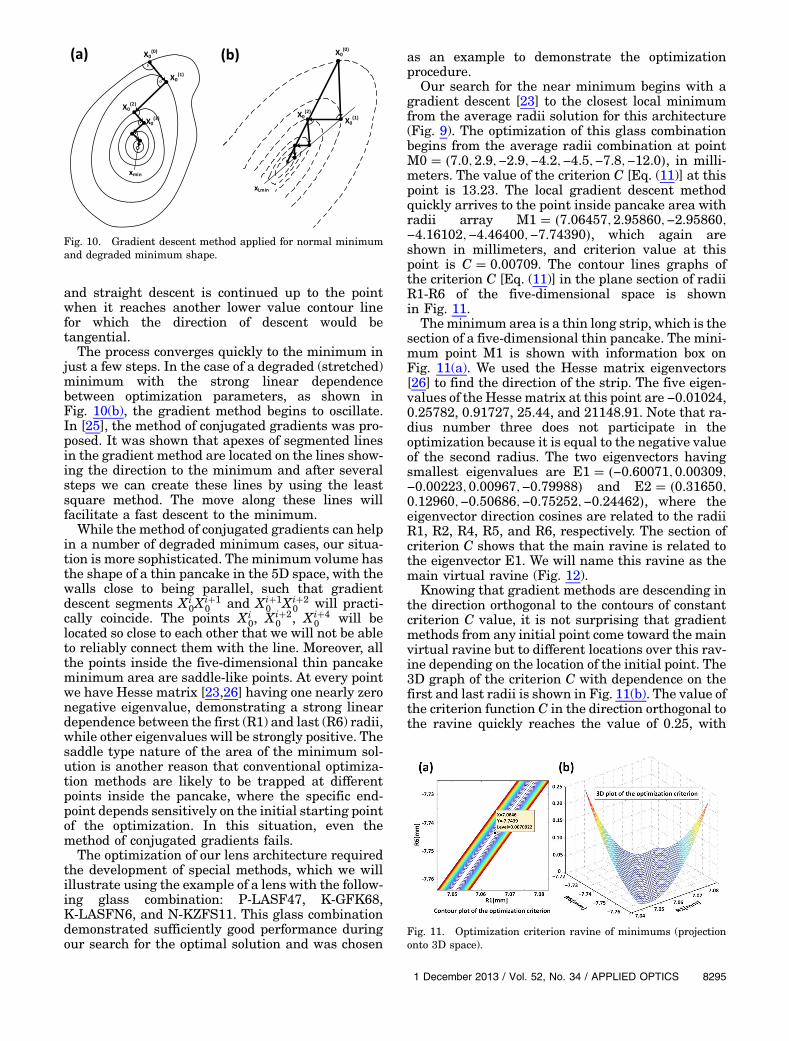
Our search for the near minimum begins with agradient descent [23] to the closest local minimumfrom the average radii solution for this architecture(Fig. 9). The optimization of this glass combinationbegins from the average radii combination at pointM0 � �7.0; 2.9;−2.9;−4.2;−4.5;−7.8;−12.0�, in milli-meters. The value of the criterion C [Eq. (11)] at thispoint is 13.23. The local gradient descent methodquickly arrives to the point inside pancake area withradii array M1 � �7.06457; 2.95860;−2.95860;−4.16102;−4.46400;−7.74390�, which again areshown in millimeters, and criterion value at thispoint is C � 0.00709. The contour lines graphs ofthe criterion C [Eq. (11)] in the plane section of radiiR1-R6 of the five-dimensional space is shownin Fig. 11.
Theminimum area is a thin long strip, which is thesection of a five-dimensional thin pancake. The mini-mum point M1 is shown with information box onFig. 11(a). We used the Hesse matrix eigenvectors[26] to find the direction of the strip. The five eigen-values of the Hesse matrix at this point are −0.01024,0.25782, 0.91727, 25.44, and 21148.91. Note that ra-dius number three does not participate in theoptimization because it is equal to the negative valueof the second radius. The two eigenvectors havingsmallest eigenvalues are E1 � �−0.60071; 0.00309;−0.00223; 0.00967;−0.79988� and E2 � �0.31650;0.12960;−0.50686;−0.75252;−0.24462�, where theeigenvector direction cosines are related to the radiiR1, R2, R4, R5, and R6, respectively. The section ofcriterion C shows that the main ravine is related tothe eigenvector E1. We will name this ravine as themain virtual ravine (Fig. 12).
Knowing that gradient methods are descending inthe direction orthogonal to the contours of constantcriterion C value, it is not surprising that gradientmethods from any initial point come toward the mainvirtual ravine but to different locations over this rav-ine depending on the location of the initial point. The3D graph of the criterion C with dependence on thefirst and last radii is shown in Fig. 11(b). The value ofthe criterion function C in the direction orthogonal tothe ravine quickly reaches the value of 0.25, with
Fig. 10. Gradient descent method applied for normal minimumand degraded minimum shape.
Fig. 11. Optimization criterion ravine of minimums (projectiononto 3D space).
1 December 2013 / Vol. 52, No. 34 / APPLIED OPTICS 8295

radii space step size as small as 0.02 mm.We will usethe main ravine as an entrance area into the pancakespace. The ravine is located very close to the straightline associated with the eigenvector E1 (the blackdotted line in Fig. 12). We travel over this straightline that is defined by the first eigenvector directionat the point of the minimum M1 and make a numberof local optimizations, which will quickly come to theactual lowest point of the ravines.
Following over the direction of eigenvector E1 wemade 17 steps with 0.05 increments in the radiispace (8 steps in the direction of lower first radiusand 8 steps in the opposite direction) and, makingthe gradient descent from each point, obtained thearray of minimums. Table 2 shows the central 10minimums (ravine bottom points) of this scan withminimum M1 over the main ravine at place number9. Table 2 shows that minimums are located over adeep and slightly curved ravine, with a strong lineardependence between the first and last radii.
The body of the pancake shaped minimum is lo-cated over the 3D sphere inside the 5D space, andthis sphere is orthogonal to the ravine, as shownin Fig. 11(b). The directions of the minimum incre-ment of the criterion C at each bottom point overthe ravine is a direction of the second eigenvectorwhile the first one is still directed over the ravine.The tunnels into the pancake (black dashed linesin Fig. 12) [26] are located over the directions ofsecond eigenvectors. These vectors are orthogonalto the ravines (blue dash-dot lines in Fig. 12).
To find the point of the criterion C minimum wecrossed the ravine structure inside the pancake areaof solutions from the point M1 in the direction of thesecond eigenvector E2. Then we initiated local gra-dient descents with the step of 0.025 mm. Valuesof C over this line after local gradient descents are0.00709 (point M1), then [0.00622, 0.00558,0.00504, 0.00470, 0.00439, 0.00412, 0.000400,0.00393. 0.00392, 0.00399]. The ravine with theminimum value of criterion C is at the point M2,having C � 0.00392 and the array of radii isM2��7.13558;2.98846;−2.98846;−4.27410;−4.63395;−7.79880�. Then we made 17 steps along eigenvectorE1 of this ravine with the short gradient descent. Thevalues of C over ravine are [0.00431, 0.00424,0.00413, 0.00405, 0.00401, 0.00399, 0.00394,0.00395, 0.00393, 0.00392, 0.00391, 0.00394,0.00395, 0.00396, 0.00404, 0.00413, 0.00418]. Theminimum value of C � 0.00391 is at the pointM3 with array of radii M3 � �7.10544; 2.98890;−2.98890;−4.27469;−4.63355;−7.83869�.
We performed this whole operation in cycles untilthe step when the minimum is located at the initialpoint of the last cycle. The whole optimization path isshown by the solid red line in Fig. 12.
Values of C around M3 are [0.00426, 0.00425,0.00405, 0.00391, 0.00385, 0.00388, 0.00394], wherethe new minimum point M4 has C � 0.00385, andarray of radii M4 � �7.09785; 2.98510;−2.98510;−4.26180;−4.61467;−7.83319�. The next step alongthis new ravine associated with the point M4gives the point M5 at one step from M4 withC � 0.00384. The array of radii at M5 isM5��7.08293;2.98531;−2.98531;−4.26206;−4.61453;−7.85324�.
The next crossing of the ravines did not succeedand the minimum C point remained at the pointM5, indicating that we had approached the limit ofthis process. The next step was to substitute the ar-ray of radii at the point M5 with C � 0.00384 intoZEMAX software, where we obtained the MTF valueof 0.54 at 200 lp∕mm frequency. After that we usedthe standard Zemax process for a local optimizationof the optical prescription to obtain the maximumMTF. The final results are shown in Table 3. Forthe MTF optimized scheme MTF at 200 lp∕mm is0.567. It is slightly better than we had at the opti-mum point of criterion C (Eq. 11). The construction
Fig. 12. Optimization procedure inside the 4GA-8 optimizationspace.
Table 2. Array of Local Minimums Over the Main Ravine in 4GA-8 Optimization Space.a
5 6 7 8 9 10 11 12 13 14
Cinitial 0.0132 0.0089 0.0074 0.0071 0.0071 0.0071 0.0075 0.0092 0.0135 0.0220r1 6.945 6.975 7.005 7.035 7.065 7.010 7.125 7.155 7.186 7.216r2 2.959 2.959 2.959 2.959 2.959 2.959 2.958 2.959 2.956 2.957r3 −2.959 −2.959 −2.959 −2.959 −2.959 −2.959 −2.959 −2.963 −2.956 −2.957r4 −4.162 −4.162 −4.161 −4.161 −4.161 −4.161 −4.161 −4.161 −4.161 −4.161r5 −4.462 −4.462 −4.463 −4.463 −4.464 −4.464 −4.465 −4.465 −4.466 −4.466r6 −7.904 −7.864 −7.824 −7.784 −7.744 −7.704 −7.664 −7.624 −7.584 −7.544Cfinal 0.0072 0.0071 0.0071 0.0071 0.0071 0.0071 0.0072 0.0073 0.0075 0.0078
aRadii shown pertain to the areas at the bottom of the ravine reached after optimization.
8296 APPLIED OPTICS / Vol. 52, No. 34 / 1 December 2013

of a low burden computer criterion from the results ofraytracing, which will perfectly correlate withMTF performance, is still an open problem [24,27].However, we consider that our criterion is in goodcorrelation with MTF, allowing us to sort the resultsof the search for 4GA-8 architecture.
The optimization process from the different initialpoint MR0 having R1 � 7.5 mm shows another solu-tion inside the neighboring pancake area on the right(Fig. 12), with the value of C � 0.00337. The opti-mized MTF at frequency 200 lp∕m for this solutionis 0.575. The optical prescription is shown in theTable 4.
Similarly, the next optimization process from theinitial point ML0 having R1 � 6.5 mm shows an-other solution inside the neighboring pancake onthe left with C � 0.00402. The optimized MTFat fre-quency 200 lp∕m for this solution is 0.562. The opti-cal prescription is shown in the Table 5. In the global
search among these three feasible solutions we pre-fer the solutions of first type shown in Table 3, asthey have the smallest weight.
The procedure described above was applied on allother glass combinations, and our near-global searchresulted in 350 top solutions that are grouped inseven distinctive families (Table 6). Glasses are con-sidered replacement glasses if their index of refrac-tion is within �0.03 range and Abbe number in �3range of glasses shown in the table.
The example solution discussed before, shown inTables 3–5, belongs to the first family of solutions.Figure 13 shows the optical layout of the lens andMTF curves of the top solution from the first familyand compares it with the seededHammer result fromFig. 8(b). The prescription of this near-global opti-mum solution is shown in Table 7. Upon inspectionof the full solutions list, the seeded Hammer solutionwas located with C � 0.006354 near-global searchcriterion value and obviously far outside the topsolutions families.
Our near global 5D search improved the MTF per-formance at 200 lp∕mm over the seeded Hammersolution by a 16% margin. Figure 14 shows graphsof sensitivities of the front and back-illuminatedsilicon sensors [28].
Our next goal was to modify the 400–1000 nm4GA-8 solution from Table 3 to operate with front-illuminated silicon sensor.
We constructed ZEMAX merit function as a func-tion keeping at minimum radii of point spread func-tions at all nine wavelengths (operators REAR),maximizing MTF at frequencies 100, 160, and200 lp∕mm and keeping the focal length at 12 mm(operator EFFL).
Substitution of the wavelength weights for thefront-illuminated silicon sensor and quick reoptim-ization in ZEMAX gave the optical prescriptionshown in Table 8.
The image quality is practically diffraction limited.The MTF of the lens is shown in the Fig. 15. At the200 lp∕mm the lens has 90% level of diffraction lim-ited resolution. Back-illuminated silicon sensors aresensitive to as low as 200 nm wavelength. We foundthat achromatization in 200–1050 nm waveband isout of ability of the 4GA-8 architecture at this scaleand aperture.
In order to avoid the use of expensive coatingswe decided to cut off the UV spectrum by usingthe mounting meniscus made from the SchottGG435 absorptive glass. Using an additionalmounting meniscus at the curved image surface isoptional and has little impact on imaging systemperformance.
The optical prescription of themonocentric lens op-erating with the back-illuminated silicon sensor isshown in Table 9. GG435 color glass refraction indi-ces were measured with Filmetrix F10-RT refrac-tometer. The MTF and the layout of the lens areshown in the Fig. 16. The image quality is close todiffraction limited.
Table 3. Optical Prescription of the 400–1000 nm F/1.7 f � 12 mmMCLens Example Solution A � 5.63 g
Radius Thickness Glass Semi-Diameter
OBJ Infinity Infinity Infinity1 7.05918 4.10337 P-LASF47 6.751212 2.95581 2.95581 K-GFK68 2.93356STO Infinity 2.95581 K-GFK68 2.209894 −2.95581 1.26426 K-LASFN6 2.916465 −4.22007 0.35576 4.055646 −4.57583 3.27037 N-KZFS11 4.341407 −7.84620 4.14501 7.12060IMA −11.9913 10.38526
Table 4. Optical Prescription of the 400–1000 nm F/1.7 f � 12 mmMCLens Example Solution B � 5.71 g
Radius Thickness Glass Semi-Diameter
OBJ Infinity Infinity Infinity1 7.26696 4.34654 P-LASF47 6.938392 2.92041 2.92041 K-GFK68 2.89944STO Infinity 2.92041 K-GFK68 2.206924 −2.92041 1.29818 K-LASFN6 2.884605 −4.21859 0.41330 4.057966 −4.63189 3.00543 N-KZFS11 4.391237 −7.63733 4.35056 6.95098IMA −11.98789 10.38221
Table 5. Optical Prescription of the 400–1000 nm F/1.7 f � 12 mmMCLens Example Solution C � 5.72 g
Radius Thickness Glass Semi-Diameter
OBJ Infinity Infinity Infinity1 6.56181 3.55968 P-LASF47 6.302322 3.00213 3.00213 K-GFK68 2.97882STO Infinity 3.00213 K-GFK68 2.217074 −3.00213 1.16917 K-LASFN6 2.957185 −4.17130 0.24397 4.004436 −4.41527 4.06139 N-KZFS11 4.198537 −8.47720 3.51334 7.62830IMA −11.99054 10.38469
1 December 2013 / Vol. 52, No. 34 / APPLIED OPTICS 8297

Both lenses have the core glass K-GFK68 with avery high coefficient of thermal expansion,TCE � 12.9, while surrounding glasses have lowTCE coefficients. For example, the front-illuminatedsilicon sensor lens shown in Table 8: P-LASF47 glasshas TCE � 6.04 and K-LASFN6 glass hasTCE � 5.9. Normally the TCE difference less than1.5 for cemented surfaces can be recommended foroutdoor optics [29]. Recently Norland Products Inc.offered extremely low psi modulus NOA 76 [30]
optical cement, which can be used for glass pairs withsuch high CTE differences.
ZEMAX thermal modeling of the schemes shownin Tables 8 and 9 with a 10 micrometer thick layerof NOA 76 optical cement for differential thermalexpansion shows that the lenses can operate in awide temperature range of −20 C to �50 C withoutimage quality degradation. Only a 0.02 mm backfocal length adjustment is required. Since monocen-tric lenses were originally designed to be usedwith refocusing [8], this procedure does not pose aproblem.
Finally, if we ask ourselves why the 4GA-8 archi-tecture has such capabilities for achieving the highperformance monocentric designs, the answer lays
Table 6. Families of Solutions for F/1.7 12 mm Monocentric 4GA-8 400–1000 nm Lens Obtained Through Near-Global Search
Family 1st Glass 2nd Glass (Core) 3rd Glass 4th Glass (Meniscus) Near-Global Search Criterion MTF at 200 lp∕mm
I P-LASF50 K-GFK68 TAF1 E-ADF10 0.003253 0.583II NBFD11 K-GFK68 TAF3 KZFS12 0.003572 0.569III L-LAM72 K-GFK68 TAF1 S-NBH53 0.003591 0.567IV TAF2 K-GFK68 P-LASF50 N-KZFS11 0.003808 0.577V L-LAH83 K-GFK68 NBF1 KZFS12 0.003958 0.555VI TAFD30 K-GFK68 P-LASF50 N-KZFS11 0.003970 0.559VII P-LASF51 K-GFK68 S-LAH58 N-KZFS11 0.003978 0.553
Fig. 13. MTF curves for 12 mm, F/1.7, 400–1000 nm lenses ob-tained through seeded Hammer search and near global five-dimensional optimization (shown on layout).
Table 7. Optical Prescription of the 400–1000 nm F/1.7 f � 12 mmMonocentric Near Global Solution
Radius Thickness Glass Semi-Diameter
OBJ Infinity Infinity Infinity1 7.05656 4.20075 P-LASF50 6.750082 2.85581 2.85581 K-GFK68 2.83814STO Infinity 2.85581 K-GFK68 2.207094 −2.85581 1.30890 TAF1 2.825075 −4.16471 0.42696 4.007446 −4.59167 3.54357 E-ADF10 4.350457 −8.13525 3.84990 7.34868IMA −11.98514 10.37980
Fig. 14. Spectral response of front and back-illuminated siliconsensor.
Table 8. Optical Prescription of the 400–1000 nm F/1.7 f � 12 mmMonocentric Lens Operating with Front-Illuminated Silicon Sensor
Radius Thickness Glass Semi-Diameter
OBJ Infinity Infinity Infinity1 7.04107 4.08409 P-LASF47 6.735082 2.95699 2.95699 K-GFK68 2.93476STO Infinity 2.95699 K-GFK68 2.211034 −2.95699 1.26003 K-LASFN6 2.917585 −4.21702 0.35134 4.052826 −4.56835 3.30232 N-KZFS11 4.334947 −7.87067 4.12587 7.14073IMA −11.99654 10.38982
8298 APPLIED OPTICS / Vol. 52, No. 34 / 1 December 2013
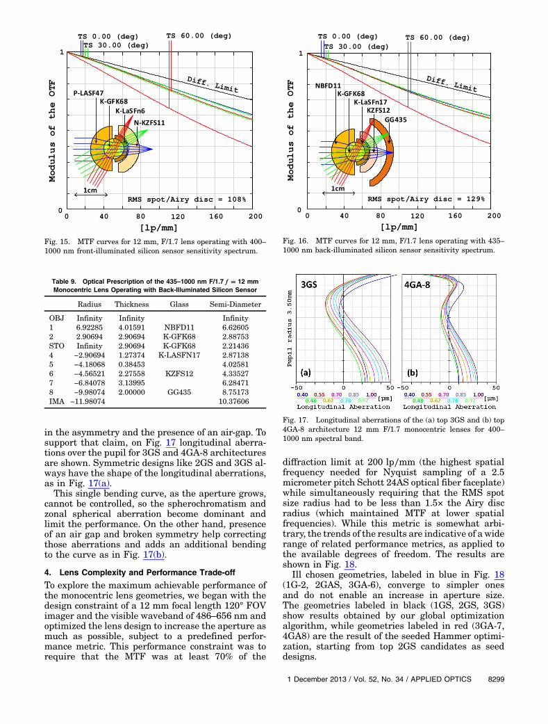
in the asymmetry and the presence of an air-gap. Tosupport that claim, on Fig. 17 longitudinal aberra-tions over the pupil for 3GS and 4GA-8 architecturesare shown. Symmetric designs like 2GS and 3GS al-ways have the shape of the longitudinal aberrations,as in Fig. 17(a).
This single bending curve, as the aperture grows,cannot be controlled, so the spherochromatism andzonal spherical aberration become dominant andlimit the performance. On the other hand, presenceof an air gap and broken symmetry help correctingthose aberrations and adds an additional bendingto the curve as in Fig. 17(b).
4. Lens Complexity and Performance Trade-off
To explore the maximum achievable performance ofthe monocentric lens geometries, we began with thedesign constraint of a 12 mm focal length 120° FOVimager and the visible waveband of 486–656 nm andoptimized the lens design to increase the aperture asmuch as possible, subject to a predefined perfor-mance metric. This performance constraint was torequire that the MTF was at least 70% of the
diffraction limit at 200 lp∕mm (the highest spatialfrequency needed for Nyquist sampling of a 2.5micrometer pitch Schott 24AS optical fiber faceplate)while simultaneously requiring that the RMS spotsize radius had to be less than 1.5× the Airy discradius (which maintained MTF at lower spatialfrequencies). While this metric is somewhat arbi-trary, the trends of the results are indicative of a widerange of related performance metrics, as applied tothe available degrees of freedom. The results areshown in Fig. 18.
Ill chosen geometries, labeled in blue in Fig. 18(1G-2, 2GAS, 3GA-6), converge to simpler onesand do not enable an increase in aperture size.The geometries labeled in black (1GS, 2GS, 3GS)show results obtained by our global optimizationalgorithm, while geometries labeled in red (3GA-7,4GA8) are the result of the seeded Hammer optimi-zation, starting from top 2GS candidates as seeddesigns.
Fig. 15. MTF curves for 12 mm, F/1.7 lens operating with 400–1000 nm front-illuminated silicon sensor sensitivity spectrum.
Table 9. Optical Prescription of the 435–1000 nm F/1.7 f � 12 mmMonocentric Lens Operating with Back-Illuminated Silicon Sensor
Radius Thickness Glass Semi-Diameter
OBJ Infinity Infinity Infinity1 6.92285 4.01591 NBFD11 6.626052 2.90694 2.90694 K-GFK68 2.88753STO Infinity 2.90694 K-GFK68 2.214364 −2.90694 1.27374 K-LASFN17 2.871385 −4.18068 0.38453 4.025816 −4.56521 2.27558 KZFS12 4.335277 −6.84078 3.13995 6.284718 −9.98074 2.00000 GG435 8.75173IMA −11.98074 10.37606
Fig. 16. MTF curves for 12 mm, F/1.7 lens operating with 435–1000 nm back-illuminated silicon sensor sensitivity spectrum.
Fig. 17. Longitudinal aberrations of the (a) top 3GS and (b) top4GA-8 architecture 12 mm F/1.7 monocentric lenses for 400–1000 nm spectral band.
1 December 2013 / Vol. 52, No. 34 / APPLIED OPTICS 8299

Adding the second glass is helpful in controllingthe chromatic aberration, so there is a large increasein achievable F-number in moving from geometry1GS to 2GS. This is equivalent to going from a singletlens to a cemented doublet achromat. Adding thethird glass in the 3GS geometry gives marginal
chromatic aberrations improvement over 2GS,whereas the other degrees of freedom (specifically,2GAS with 4 DOF, and 3GA-6 with 6 DOF) provideno improvement.
Breaking the symmetry and introducing an air gapwith the 7 DOFand 8 DOFarchitectures allows us tofurther increase the aperture, and still meet thedesired MTF performance. Similar behavior is ob-served for the longer 112 mm focal length lens, whichis also shown in Fig. 18.
The final step was to explore the design space forfour different focal length scales {f � 12 mm (theSCENICC program lens scale), 40 mm, 70 mm(AWARE2 program [1]) and 112 mm (AWARE10program [31])}, and at each scale look at the maxi-mum aperture for visible, extended visible, andvisible-NIR spectral wavebands, subject to theMTF performance constraint described above. Asbefore, we used the global optimization for thetwo-glass and three-glass symmetric systems (2GS,3GS). For the three- and four-glass air gap candi-dates (3GA-7, 4GA-8), the combination of our system-atic fifth-dimensional optimizer with ZEMAXhammer optimization was used. The entire set ofresults is summarized in Fig. 19. The clear trendis maintained over all three spectral bands and itshows the necessity of lens structure complexity
Fig. 18. Monocentric lens geometries optimization behavior fortwo different scales operating in 486–656 nm spectral range.
Fig. 19. Monocentric objective lens performance trade-off for different scales and three spectral bands (486–656 nm, 435–850 nm,400–1000 nm).
8300 APPLIED OPTICS / Vol. 52, No. 34 / 1 December 2013
increase if we wish to push the scale and/or the aper-ture size. For the time being, the area above pink4GA-8 line remains terra incognita where the com-plexity and manufacturing cost increase outweighsthe performance improvements. One exception tothat rule is 5GA-10 architecture, which can be quiteuseful for medium scale (>100 mm) and large scaledesigns and will be demonstrated in an example inSection 5. 2GS global search still remains a powerfultool in monocentric lens design, both for supplyingthe final or seed designs for the more complex archi-tectures. While the five-dimensional near-globalsearch gives substantially better results over the2GS seeded Hammer search, completing it on 32CPU cores at this point is very time consuming andshould be used only as a final attempt to squeeze outthe maximum performance capability from the lensbefore manufacturing. Implementing the code for the5D near global search on GPUs would possiblyreduce the search time by a factor of hundred cuttingit down from weeks to hours.
5. Specific Lens Design Examples
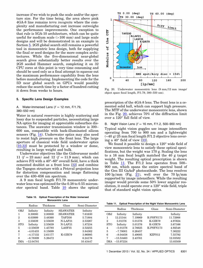
A. Water-Immersed Lens (f � 12 mm, F/1.79,380–550 nm)
Water in natural reservoirs is highly scattering andlossy due to suspended particles, necessitating largeNA optics for imaging at appreciable subsurface dis-tances. The seawater transmission window is 300–600 nm, compatible with back-illuminated siliconsensors (Fig. 14). Underwater optics may also needto resist high pressure on the front lens. The largeaperture of classical wide field underwater optics[10,32] must be protected by a window or dome,resulting in large weight and bulk.
Underwater objectives like the Gidrorussar model11 (f � 23 mm) and 12 (f � 11.9 mm), which canachieve F/2 with a 40°–60° overall field, have a thickcemented doublet as a front lens [32] and combinethe Topogon structure with a Petzval projection lensfor distortion compensation and image flatteningover the 430–656 nm spectrum.
A 9 mm focal length F/1.79 monocentric under-water lens was optimized for the 0.38 to 0.55 microm-eter spectral band. Table 10 shows the optical
prescription of the 4GA-8 lens. The front lens is a ce-mented solid ball, which can support high pressure.The MTF of the underwater monocentric lens, shownin the Fig. 20, achieves 70% of the diffraction limitover a 120° full field of view.
B. Night Vision Lens (f � 16 mm, F/1.2, 500–900 nm)
Typical night vision goggles use image intensifiersoperating from 700 to 900 nm and a lightweight(∼40 g) 25 mm focal length F/1.2 objective lens cover-ing a 40° field of view [33].
We found it possible to design a 120° wide field ofview monocentric lens to satisfy these optical speci-fications, but the weight was 170 g. Scaling the lensto a 16 mm focal length matched the 40 g targetweight. The resulting optical prescription is shownin Table 11. The F/1.2 lens operates from 500–900 nm, which spans the entire spectral band ofthe Gen III GaAsP photocathode. The lens resolves100 lp∕mm (Fig. 21), well over the 70 lp∕mmsupported by image intensifiers. While the resultingimager would provide some 50% lower angular res-olution, it could operate over a 120° wide field, triplethat of standard night vision optics.
Table 10. Optical Prescription of the Water ImmersedMonocentric Lens
Radius Thickness Glass Semi-Diameter
OBJ Infinity Infinity SEAWATER Infinity1 8.30000 2.00000 SEAWATER 7.616302 6.03999 3.48360 TAFD30 5.718843 2.55639 2.55639 N-LAF21 2.53267STO Infinity 2.55639 N-LAF21 1.872345 −2.55639 1.45793 LASF35 2.522556 −4.01433 0.15699 3.843627 −4.17132 2.61177 K-GIR79 3.969958 −6.78309 5.26472 6.24176IMA −12.04781 10.43447
Fig. 20. Underwater monocentric lens (9 mm∕12 mm image/object space focal length, F/1.79, 380–550 nm).
Table 11. Optical Prescription of the Night Vision Monocentric Lens
Radius Thickness Glass Semi-Diameter
OBJ Infinity Infinity Infinity1 12.21344 7.19969 K-PSFN173 11.729882 5.01376 5.01376 K-GIR79 4.97624STO Infinity 5.01376 K-GIR79 3.671664 −5.01376 2.76625 K-PSFN173 4.925485 −7.78001 0.26457 7.362226 −8.04458 5.49005 KZFS12 7.557927 −13.53463 2.43761 12.03582IMA −15.97224 13.83509
1 December 2013 / Vol. 52, No. 34 / APPLIED OPTICS 8301
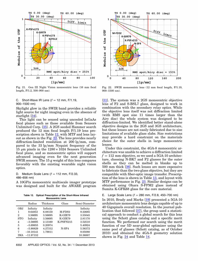
C. Short-Wave IR Lens (f � 12 mm, F/1.19,900–1500 nm)
Skylight glow in the SWIR band provides a reliablelight source for night imaging even in the absence ofstarlight [34].
This light can be sensed using uncooled InGaAsfocal planes such as those available from SensorsUnlimited Corp. [35]. A 2GS seeded Hammer searchproduced the 12 mm focal length F/1.19 lens pre-scription shown in Table 12, with MTF and lens lay-out as shown in the Fig. 22. The lens provides nearlydiffraction-limited resolution at 200 lp∕mm, com-pared to the 33 lp∕mm Nyquist frequency of the15 μm pixels in the 1280 × 1024 Sensors Unlimitedfocal plane, and so monocentric optics will supportadvanced imaging even for the next generationSWIR sensors. The 15 g weight of this lens comparesfavorably with the existing wearable night visionoptics.
D. Medium Scale Lens (f � 112 mm, F/2.33,486–656 nm)
A 10GPix monocentric multiscale imager prototypewas designed and built for the AWARE program
[31]. The system was a 2GS monocentric objectivelens of F2 and S-BSL7 glass, designed to work incombination with the secondary relay optics. Whilethe objective lens itself was not diffraction limited(with RMS spot size 11 times larger than theAiry disc) the whole system was designed to bediffraction-limited. We identified better stand-aloneobjective designs in the 2GS and 3GS architecture,but these lenses are not easily fabricated due to sizelimitations of available glass slabs. Size restrictionsmay provide a hard constraint on the materialschoice for the outer shells in large monocentriclenses.
Under this constraint, the 4GA-8 monocentric ar-chitecture was unable to achieve a diffraction limitedf � 112 mm objective, so we used a 5GA-10 architec-ture, choosing N-BK7 and F2 glasses for the outershells as they can be melted in blanks up to500 mm thick [36]. Such lenses are more expensiveto fabricate than the two-glass objective, but they arecompatible with fiber-optic image transfer. Prescrip-tion of the lens is shown in Table 13, and layout withMTF performance in Fig. 23. Similar designs can beobtained using Ohara S-FPM2 glass instead ofSumita K-GFK68 glass for the core material.
E. Large Scale Lens (f � 280 mm, F/2.8, 450–700 nm)
In 2010, Brady and Marks [19] presented a 5GA-10architecture monocentric lens design capable of up to40 Gigapixels overall resolution. In the journal pub-lication that followed [37], the group used a statisti-cal approach to conduct a global search for this lensusing the Schott glass catalog and a specific meritfunction. We performed our search using the meritfunction of our 5D near-global optimizer using thesame pool of glasses (Schott catalog, as of October2010) and obtained the 4GA-8 geometry solutionshown in Fig. 24 and Table 14.
Fig. 21. Gen III Night Vision monocentric lens (16 mm focallength, F/1.2, 500–900 nm).
Table 12. Optical Prescription of the Short-Wave InfraredMonocentric Lens
Radius Thickness Glass Semi-Diameter
OBJ Infinity Infinity Infinity1 9.64853 6.08158 M-FDS2 9.226852 3.56695 3.56695 K-GIR79 3.55045STO Infinity 3.56695 K-GIR79 2.811704 −3.56695 2.13160 K-PSFN215 3.525105 −5.69855 0.20974 5.409246 −5.90829 4.27312 N-SF4 5.563727 −10.18141 1.79011 9.05080IMA −11.97152 10.36887
Fig. 22. SWIR monocentric lens (12 mm focal length, F/1.19,900–1500 nm).
8302 APPLIED OPTICS / Vol. 52, No. 34 / 1 December 2013

The resulting 4GA-8 lens offers comparable sizeand weight, and slightly better MTF performance,than the 5GA-10 lens. It is necessary to note, how-ever, that both lenses would be difficult to fabricatedue to the physical thickness of the glass elementsrequired.
6. Summary and Conclusion
This paper describes an investigation of wide field ofview monocentric lenses using architectures withcomplexity ranging from a simple glass ball to mod-erately complex structures with up to 10 degrees ofdesign freedom following the focal length constraint.A 2GS lens structure works well for applications witha moderate spectral range, focal length, and numeri-cal aperture. However, for applications that substan-tially increase one or more of these specifications, weshow that the best performance in a moderate com-plexity lens is achieved with four-glass structureswith an air gap between meniscus elements behinda spherical glass core (the 4GA-8 architecture).
To help identify the best specific designs for such4GA-8 lenses, we presented a systematic optimiza-tion method derived from the global optimizationof a two-glass lens and demonstrate its capabilityfor several case studies. We conclude that the generalclass of monocentric objective lenses offers practicalhigh-performance options for a variety of wide-angleimaging systems.
This research was supported by the DARPA SCE-NICC program under contract W911NF-11-C-0210and by the DARPA AWARE program under contractHR0011-10C-0073.
References1. D. J. Brady, M. E. Gehm, R. A. Stack, D. L. Marks, D. S. Kittle,
D. R. Golish, E. M. Vera, and S. D. Feller, “Multiscale gigapixelphotography,” Nature 486, 386–389 (2012).
2. J. E. Ford and E. Tremblay, “Extreme form factor imagers,” inImaging Systems, OSA Technical Digest (CD) (Optical Societyof America, 2010), paper IMC2.
3. E. J. Tremblay, D. L. Marks, D. J. Brady, and J. E. Ford,“Design and scaling of monocentric multiscale imagers,” Appl.Opt. 51, 4691–4702 (2012).
4. J. A. Waidelich, Jr., “Spherical lens imaging device,” U.S.patent 3,166,623 (19 January 1965).
5. T. S. Axelrod, N. J. Colella, and A. G. Ledebuhr, “Thewide-field-of-view camera,” in Energy and TechnologyReview, (Lawrence Livermore National Laboratory, 1988).
Table 13. Optical Prescription of the f � 112 mm MonocentricLens Candidate
Radius Thickness Glass Semi-Diameter
OBJ Infinity Infinity Infinity1 70.6495 25.0385 F2 66.02622 45.6110 20.0201 N-LASF31A 43.43943 25.5910 25.5910 K-GFK68 25.0475STO Infinity 25.5910 K-GFK68 15.09005 −25.5910 11.0541 N-LASF31A 24.82566 −36.6451 5.7785 34.69247 −42.4236 34.4507 N-BK7 39.41288 −76.8743 35.0734 68.5323IMA −111.9476 96.9500
Fig. 23. Medium scale monocentric lens 5GA-10 diffraction lim-ited candidate possible to fabricate (112 mm focal length, F/2.33,486–656 nm).
Table 14. Optical Prescription of the Optimal 40GPix Monocentric4GA-8 Lens
Radius Thickness Glass Semi-Diameter
OBJ Infinity Infinity Infinity1 122.6509 65.5070 N-LAK33B 116.10512 57.1440 57.1440 CAF2 56.0001STO Infinity 57.1440 CAF2 34.89024 −57.1440 16.2656 N-LAK8 55.66735 −73.4095 11.4827 70.36376 −84.8922 31.3242 N-LAF34 80.00697 −116.2164 163.6565 107.5578IMA −279.8730 242.3780
Fig. 24. Polychromatic MTF comparison of previously reported5GA-10 optimal solution for the Gigagon 40GPix lens and a sim-pler 4GA-8 solution (280 mm focal length, F/2.8, 450–700 nm).
1 December 2013 / Vol. 52, No. 34 / APPLIED OPTICS 8303

6. C. Akerlof, M. Fatuzzo, B. Lee, R. Bionta, A. Ledebuhr, H.Park, S. Barthelmy, T. Cline, and N. Gehrels, “Gamma-rayoptical counterpart search experiment (GROCSE),” in AIPConference Proceedings (American Institute of Physics,1994), Vol. 307, pp. 633–637.
7. J. F. Kordas, I. T. Lewis, B. A. Wilson, D. P. Nielsen, H. Park,R. E. Priest, R. Hills, M. J. Shannon, A. G. Ledebuhr, and L. D.Pleasance, “Star tracker stellar compass for the Clementinemission,” Proc. SPIE 2466, 70 (1995).
8. I. Stamenov, I. Agurok, and J. Ford, “Optimization of two-glassmonocentric lenses for compact panoramic imagers: generalaberration analysis and specific designs,” Appl. Opt. 51,7648–7661 (2012).
9. J. Ford, I. Stamenov, S. Olivas, G. Schuster, N. Motamedi, I.Agurok, R. Stack, A. Johnson, and R. Morrison, “Fiber-coupledmonocentric lens imaging,” in Imaging and Applied Optics, J.Christou and D. Miller, eds. OSA Technical Digest (online)(Optical Society of America, 2013), paper CW4C.2.
10. W. Smith, Modern Lens Design, 2nd ed. (McGraw-Hill,2005).
11. J. M. Cobb, D. Kessler, and J. Agostinelli, “Optical design of amonocentric autostereoscopic immersive display,” Proc. SPIE4832, 80–90 (2002).
12. G. Krishnan and S. K. Nayar, “Towards a true sphericalcamera,” Proc. SPIE 7240, 724002 (2009).
13. O. Cossairt, D. Miau, and S. K. Nayar, “Gigapixel computa-tional imaging,” in IEEE International Conference on Compu-tational Photography (IEEE, 2011).
14. R. Kingslake, A History of the Photographic Lens (Academic,1989), pp. 49–67.
15. H. Son, D. L. Marks, E. J. Tremblay, J. Ford, J. Hahn, R. Stack,A. Johnson, P. McLaughlin, J. Shaw, J. Kim, and D. J. Brady,“A multiscale, wide field, gigapixel camera,” in ImagingSystems Applications, OSA Technical Digest (Optical Societyof America, 2011), paper JTuE2.
16. J. Oakley, “Whole-angle spherical retroreflector using concen-tric layers of homogeneous optical media,” Appl. Opt. 46,1026–1031 (2007).
17. M. Born and E. Wolf, Principles of Optics 7th ed. (CambridgeUniversity, 1999).
18. I. Stamenov, I. Agurok, and J. Ford, “Capabilities of monocen-tric objective lenses,” in Imaging and Applied Optics, J.
Christou and D. Miller, eds. OSA Technical Digest (online)(Optical Society of America, 2013), paper ITu3E.4.
19. D. Marks and D. Brady, “Gigagon: a monocentric lens designimaging 40 gigapixels,” in Imaging System OSA TechnicalDigest (CD) (Optical Society of America, 2010).
20. R. Kingslake and R. B. Johnson, Lens Design Fundamentals,2nd ed. (SPIE, 2010).
21. G. G. Slyusarev, Aberrations and Optical Design Theory, 2nded. (Adam Hilger, 1984).
22. M. M. Rusinov, Handbook of Computational Optics(Mashinostroenie, 1984), Chap. 23.
23. P. Gill, W. Murray, and M. Wright, Practical Optimization(Academic, 1981).
24. S. A. Rodionov, Computer Lens Design (Mashinostroenie,1982).
25. D. Feder, “Automatic optical design,” Appl. Opt. 2, 1209–1226(1963).
26. G. Golub and C. Van Loan, Matrix Computations (JohnHopkins, 1989).
27. R. Shannon, The Art and Science of Optical Design(Cambridge University, 1997).
28. http://www.andor.com/learning‑academy/ccd‑spectral‑response‑(qe)‑defining‑the‑qe‑of‑a‑ccd.
29. M. Kruger, B. Panov, B. Kulagin, G. Pogarev, Y. Kruger, andA. Levinson, “Handbook of opto-mechanics,” Moscow,1963.
30. www.norlandprod.com.31. D. L. Marks, H. S. Son, J. Kim, and D. Brady, “Engineering a
gigapixel monocentric multiscale camera,” Opt. Eng. 51,083202 (2012).
32. M. Rusinov, Composition of Optical Systems (Mashinostroe-nie, 1989).
33. www.morovision.com.34. D. Dayton, J. Gonglewsky, C. Arnauld, I. Mons, and D. Burns,
SWIR Sky Glow Cloud Correlation with NIR and VisibleClouds: An Urban and Rural Comparison (AFRL, 2009).
35. www.sensorsinc.com.36. www.schott.com, TIE-41 Large Optical Glass Blanks,
Technical information document.37. N. Zheng, S. C. Schmidler, D. Marks, and D. Brady, “Computer
experiment and global optimization of layered monocentriclens systems,” Optik 123, 1249–1259 (2012).
8304 APPLIED OPTICS / Vol. 52, No. 34 / 1 December 2013