Embed Size (px)
Citation preview

Liquid crystal lens focusing in monocentric multiscale imagers
Igor Stamenov*a, Eric Tremblayb, Katherine A. Bakera, Paul McLaughlinc, Joseph E. Forda
aDepartment of Electrical and Computer Engineering, University of California, San Diego, 9500 Gilman Drive, La Jolla, CA 92093-0409; bEcole Polytechnique Fédérale de Lausanne, Lausanne,
Switzerland; cRPC Photonics, 330 Clay Road, Rochester, NY 14623
*[email protected]; phone (858) 822-4406; psilab.ucsd.edu
ABSTRACT
In multiscale imagers a single objective lens is shared by multiple secondary optical systems, so that a high-resolution wide-angle image is acquired in overlapping fields sensed by multiple conventional focal planes. In the “AWARE2” 2 Gigapixel imager, F/2.4 optics cover a 120 degree field of view using a monocentric glass primary lens shared by 221 molded plastic subimagers, each with a 14 Megapixel focal plane. Such imagers can independently focus parts of the image field, allowing wide-angle imaging over relatively close and deep image fields. However, providing hundreds of independent mechanical focus adjustments has a significant system impact in terms of complexity, bulk, and cost. In this paper we explore the use of an electronically controlled liquid crystal lens for focus of multiscale imagers in general, and demonstrate use with the AWARE2 imager optics. The Lens Vector Auto Focus (LVAF) liquid crystal lens provides up to 5 diopters of optical power over a 2.2mm aperture diameter, the maximum currently available aperture. However, a custom lens using the same materials and basic structure can provide the 5 diopters power and 6.4 mm aperture required to obtain full resolution overlapping image fields in the AWARE2 imager. We characterize the LVAF lens and the optical performance of the LVAF lens in the current AWARE2 prototype, comparing the measured and optically modeled resolution, and demonstrating software control of focus from infinity to an 2m object distance.
Keywords: Monocentric imager, liquid crystal lens, Gigapixel, focusing mechanism, LC focus, Multiscale monocentric, wide field, panoramic.
1. INTRODUCTION Imagers that require the combination of wide field of view, high angular resolution and large light collection present a difficult challenge in optical system design. Geometric lens aberrations increase with aperture diameter, numerical aperture and field of view, and scale linearly with focal length. This means that for a sufficiently short focal length, it is possible to find near diffraction-limited wide angle lens designs, including lenses mass-produced for cellphone imagers. However, light collection (which is determined by entrance pupil diameter), and angular resolution (for a fixed sensor pixel pitch) both demand longer focal lengths. Conventional lens designs for longer focal length wide-angle lenses represent a tradeoff between competing factors of light collection, volume, and angular resolution. For example, conventional "fisheye" lenses provide extremely limited light collection compared to their large input aperture and overall volume1. However, the problem goes beyond the lens itself. Solving this lens design only leads to a secondary design constraint, in that the total resolution of such wide angle lenses can easily exceed 100 Megapixels. This is beyond the current spatial resolution and communications bandwidth of a single cost-effective sensor2, especially for video output at 30 frames per second or more.
1.1 Wide angle monocentric lens imaging
One early solution to wide-angle imaging was "monocentric" lenses3, using only hemispherical or spherical optical surfaces that share a single center of curvature. This symmetry yields zero coma or astigmatism over a hemispherical image surface, and on that surface provides a field of view limited only by vignetting from the central aperture stop. The challenge of using a curved image surface limited the practical application of this type of lens, but there has been a resurgence of interest in monocentric lens imaging. In 2009, Krishnan and Nayar proposed an omnidirectional imager using a spherical ball lens contained within a spherical detector shell4. In 2010 Ford and Tremblay5 proposed using a monocentric lens as the objective in a multiscale imager system6, where overlapping regions of the spherical image
Current Developments in Lens Design and Optical Engineering XIII, edited by R. Barry Johnson,Virendra N. Mahajan, Simon Thibault, Proc. of SPIE Vol. 8486, 84860V© 2012 SPIE · CCC code: 0277-786/12/$18 · doi: 10.1117/12.930249
Proc. of SPIE Vol. 8486 84860V-1

%bi144,-,''' . .
surface are relayed onto conventional image sensors, and where the mosaic of sub-images can be digitally processed to form a single aggregate image. Cossiart and Nayar demonstrated a closely related configuration using a glass ball and single element relay lenses, recording and digitally combining overlapping images from 5 adjacent image sensors7. And recently a Gigapixel monocentric multiscale AWARE-2 imager has been demonstrated which integrates a 2-dimensional mosaic of sub-images8,9, using the optical layout shown in Figure 110.
Figure 1. Optical layout of a 2.4GPix monocentric AWARE2 lens and shaded model with partially populated spherical image plane
Monocentric lenses and spherical image formation provides favorable scaling to long focal lengths, and have been shown capable of two orders of magnitude higher space-bandwidth product (number of resolvable spots) than conventional flat field systems of the same physical volume11. In early monocentric lens cameras, the vignetting and diffraction from the central lens aperture, as well as the ability of recording media to conform to a spherical image surface limited the usable field of view. However, the system aperture stop need not be located in the monocentric lens. The detailed design of the multiscale monocentric lens10 shows that locating the aperture stop within the secondary (relay) imagers enables uniform relative illumination and resolution over the full field. This AWARE2 design maintains F/2.4 light collection with near-diffraction limited resolution over a 120° field of view. With 1.4 micron pitch sensors, this yields an aggregate resolution of 2.4 Gigapixels.
AWARE2 monocentric imager utilizes 221 molded plastic subimagers, each with a 14Mpixel focal plane. Such imagers can independently focus parts of the image field, allowing wide-angle imaging over relatively close (~15m) and deep image fields. This results in capability of forming the whole field of view stitched image with all parts of the scene in focus, regardless of object distance from the system. Also, multiple users may observe different parts of the whole scene and have independent simultaneous focus control of subimagers responsible for imaging particular region of interest. However, providing hundreds of independent mechanical focus adjustments has a significant system impact in terms of complexity, bulk and cost. Since it requires substantial space volume behind and between the subimagers, it directly puts the constraint on optical design space of the subimagers’ optics. Large number of mechanical focusing devices have high
Proc. of SPIE Vol. 8486 84860V-2
objective
image surface
single microcamera
focalplanes
failure rate, so search for alternative focusing mechanisms is justified. In this paper we demonstrate the electronic focusing mechanism by incorporation and characterization of the Lens Vector Auto Focus liquid crystal lens (LVAF) inside the secondary subimager optical path. By software – controlled variation of the LVAF control voltage, optical power of the LVAF lens changes and monocentric imager is able to focus from infinity down to 2m object distance without deploying any movable parts.
2. EXPERIMENTAL SETUP AND METHODS 2.1 Lens Vector Autofocus liquid crystal lens (LVAF)
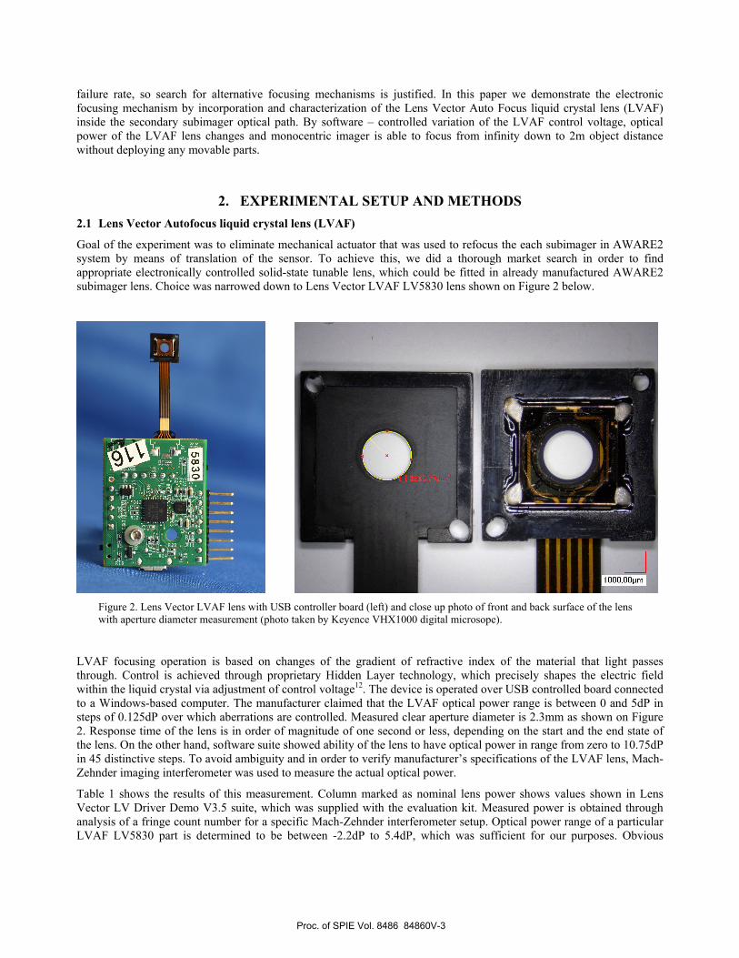
Goal of the experiment was to eliminate mechanical actuator that was used to refocus the each subimager in AWARE2 system by means of translation of the sensor. To achieve this, we did a thorough market search in order to find appropriate electronically controlled solid-state tunable lens, which could be fitted in already manufactured AWARE2 subimager lens. Choice was narrowed down to Lens Vector LVAF LV5830 lens shown on Figure 2 below.
Figure 2. Lens Vector LVAF lens with USB controller board (left) and close up photo of front and back surface of the lens with aperture diameter measurement (photo taken by Keyence VHX1000 digital microsope).
LVAF focusing operation is based on changes of the gradient of refractive index of the material that light passes through. Control is achieved through proprietary Hidden Layer technology, which precisely shapes the electric field within the liquid crystal via adjustment of control voltage12. The device is operated over USB controlled board connected to a Windows-based computer. The manufacturer claimed that the LVAF optical power range is between 0 and 5dP in steps of 0.125dP over which aberrations are controlled. Measured clear aperture diameter is 2.3mm as shown on Figure 2. Response time of the lens is in order of magnitude of one second or less, depending on the start and the end state of the lens. On the other hand, software suite showed ability of the lens to have optical power in range from zero to 10.75dP in 45 distinctive steps. To avoid ambiguity and in order to verify manufacturer’s specifications of the LVAF lens, Mach-Zehnder imaging interferometer was used to measure the actual optical power.
Table 1 shows the results of this measurement. Column marked as nominal lens power shows values shown in Lens Vector LV Driver Demo V3.5 suite, which was supplied with the evaluation kit. Measured power is obtained through analysis of a fringe count number for a specific Mach-Zehnder interferometer setup. Optical power range of a particular LVAF LV5830 part is determined to be between -2.2dP to 5.4dP, which was sufficient for our purposes. Obvious
Proc. of SPIE Vol. 8486 84860V-3

Interferogram FringeCount
Nominal lenspower [dP]
Measuredpower [dP]
5 10.75 5.4
4 8.75 4.3
Interferogram FringeCount
Nominal lenspower [dP]
Measuredpower [dP]
0 -1( ?) 1.500 -0.75
( ?)
1 1.00 -1( ?)
3 6.50 3.2
2 4.50 2.2
1 1.75 1.0
2 0.75 -2.2
2+ 0.50 -2.3 ( ?)
2+ 0.00 -2.2 ( ?)
discrepancy between actual and reported optical power is attributed to a demo version state of the software and an inability to automatically recognize the actual part model.
Table 1. LVAF inteferograms in Mach-Zehnder interferometer and measured optical power.
2.2 AWARE2 focusing and LVAF system implementation
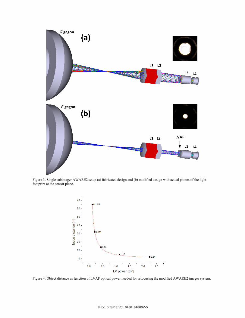
AWARE2 imager focusing is achieved by independent focusing of individual subimagers. Focusing of the individual subimager is achieved by servo motor translation of the sensor. Translation of the sensor by 0.070mm is sufficient for refocus from infinity to 15m object distance range9. AWARE2 subimager stop location is in front of L3 lens element (Figure 3) and this place was conveniently chosen as a point of insertion of LVAF lens. Subimager aperture stop diameter size is 6.4mm, which is substantially larger than LVAF 2.3mm aperture size. Therefore, use of the LVAF at aperture stop location in AWARE2 subimager blocks portion of the light beam and thus eliminates the field overlap capability of the imager. Thus, this setup can be used only to demonstrate the capability of LC lens refocusing, on expense of losing field overlapping.
Figure 3 shows the light propagation in AWARE2 system, as built, and simulated light propagation in modified system with actual light footprint at the sensor. In order to determine LVAF optical power needed to achieve refocusing of the system, Zemax simulation was done. Lens Vector directly supplied LVAF part model for Zemax. Results are shown on Figure 4.
Initially, LVAF optical power was kept at zero for infinite object distance. For each subsequent closer object distance, the LVAF Zemax model parameters were reoptimized and an effective optical power was calculated. It is obvious that for a 30m object distance the required optical power is around 0.25dP, and for 10m distance around 0.5dP was needed.
Proc. of SPIE Vol. 8486 84860V-4
LVAF
L3 L4
(dP) Jannod Al
VZz
oL so oro
z Cr
9LZL0
- o
- oI
- 09
- OL
Figure 3. Single subimager AWARE2 setup (a) fabricated design and (b) modified design with actual photos of the light footprint at the sensor plane.
Figure 4. Object distance as function of LVAF optical power needed for refocusing the modified AWARE2 imager system.
Proc. of SPIE Vol. 8486 84860V-5

Keyence VHX -1000digital microscope
1 * - . .
4.
Imatest MTF test reticle
la)
In order to test AWARE2 performance with LVAF lens in the system, two experimental setups were built. First was an indoors fixed setup built with an exploded version of a subimager lens which were not assembled in mounting barrel (Fig 5.)
Figure 5. AWARE2 exploded lens indoors system
Second, mobile system was based on already assembled and aligned subimager lens in a mounting barrel and was built for better stray light control and capability for both indoor and outdoor measurements. In order to insert the LVAF lens inside the subimager optical train, two 5.8mm slots were cut on the mounting barrel prior to assembling as shown on Figure 6. This slot was used to insert the LVAF lens just in front of the diffractive L3 element.
Figure 6. AWARE2 MC0 subimager layout and modified barrel for LVAF lens use.
Proc. of SPIE Vol. 8486 84860V-6

0.8
LL0.6
LLcd)
0.4
0.2
NW: Vertical
0 50 100 160 200 250Frequency, Cycles/mm (0.37 um/Pixel)
MTF50 = 79.1 Cy/mm
MTF30 = 113 Cy/mm
MTF10 = 228 Cy/mm
(a)
.....--, .:.300
0.8
f 0.6
0.4
0.2
MTF50 = 74.8 Cy/mm
MTF30 = 111 Cy/mm
MTF10 = 193 Cy/mm
(b)
MTF: Vertical = - -,.i i ,
50 100 150 200 250 300
Frequency, Cycles/mm (0.37 um/Pixel)
oo
Mobile version of the system was assembled inside black box and mounted on the service cart (Figure 7).
Figure 7. Mobile version of the setup taken outside on top of the CALIT2 building, Jacobs School of Engineering, UCSD.
AWARE2 imager uses Aptina MT9F002 14MPix monochrome sensors9, but in our experiment we used relay imaging with a Keyence VHX1000 digital microscope equipped with a Z20 lens.
3. RESULTS 3.1 Exploded lens indoor results
AWARE2 all-plastic MC0 subimager optics parts were individually mounted and aligned with Gigagon objective lens in front (Figure 5). A collimator was used to simulate an object at infinity, and a transparent Imatest MTF test reticle was used as an object. Images were taken by a Keyence VHX1000 digital microscope with 1600x1200 sensor resolution. Then, Imatest software was used to calculate MTF performance. The LVAF was in 0dP state. Results are shown on Figure 8.
Figure 8. MTF performance with object at infinity (a) without LVAF in system and (b) with LVAF in system in 0dP state.
Proc. of SPIE Vol. 8486 84860V-7

120
MTF50MTF30
100
80 -EC
H2
40 -
20 -
0 1/30 1/15 1/8 1/4 1/3 1/2 1/1.7
object conjugate (1 /m)
Obviously, the insertion of a LVAF lens in the system resulted in slight MTF performance drop in low and medium spatial frequencies, so it was concluded that the LVAF at zero optical power state does not contribute significantly to additional image degradation. In order to more easily deal with stray light control and to take outdoor measurements, a mobile version of setup was built.
3.2 Mobile system indoor results
The mobile system shown on Figure 7 was also tested with a Imatest MTF test reticle which simulated object distance from infinity down to 1.7m. In order to avoid ambiguity of LVAF operating near zero optical power (refer to Table 1), 1.13dP offset was introduced for the starting focusing point when an object is at infinity. Initially, after focusing to infinity, LVAF power was maintained while object distance was decreased. As expected, MTF performance dropped and is shown in Table 2 and Figure 9.
Table 2. MTF performance falloff data plotted on Figure 9.
# Object
distance [m]
MTF50 [Cyc/mm]
MTF30 [Cyc/mm]
1 Infinity 62.2 107.0 2 30 58.4 92.2 3 15 52.7 76.8 4 8 36.0 48.6 5 4 20.3 27.8 6 3 16.8 25.7 7 2 17.2 26.0 8 1.7 19.7 27.5
Figure 9. MTF falloff with object distance decrease (LVAF power kept constant at 1.13dP for optimum focus at infinity).
Proc. of SPIE Vol. 8486 84860V-8
1
-.- MTF50-*- MTF30
180 -
160 -
MTF10
140
E
ïi -H
80 -
60 -
40 -
0 1/30 1/15 1/8 1/4 1/3 1/2 1/1.7
object conjugate (1 /m)
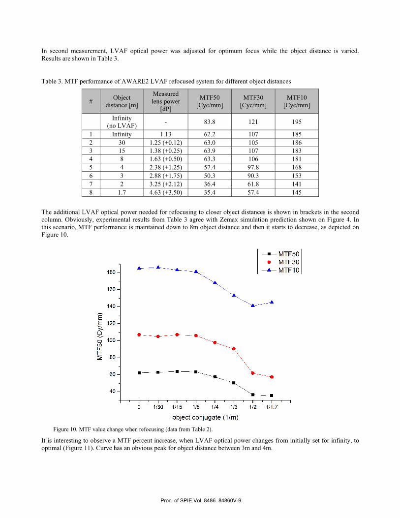
In second measurement, LVAF optical power was adjusted for optimum focus while the object distance is varied. Results are shown in Table 3.
Table 3. MTF performance of AWARE2 LVAF refocused system for different object distances
# Object distance [m]
Measured lens power
[dP]
MTF50 [Cyc/mm]
MTF30 [Cyc/mm]
MTF10 [Cyc/mm]
Infinity (no LVAF) - 83.8 121 195
1 Infinity 1.13 62.2 107 185 2 30 1.25 (+0.12) 63.0 105 186 3 15 1.38 (+0.25) 63.9 107 183 4 8 1.63 (+0.50) 63.3 106 181 5 4 2.38 (+1.25) 57.4 97.8 168 6 3 2.88 (+1.75) 50.3 90.3 153 7 2 3.25 (+2.12) 36.4 61.8 141 8 1.7 4.63 (+3.50) 35.4 57.4 145
The additional LVAF optical power needed for refocusing to closer object distances is shown in brackets in the second column. Obviously, experimental results from Table 3 agree with Zemax simulation prediction shown on Figure 4. In this scenario, MTF performance is maintained down to 8m object distance and then it starts to decrease, as depicted on Figure 10.
Figure 10. MTF value change when refocusing (data from Table 2).
It is interesting to observe a MTF percent increase, when LVAF optical power changes from initially set for infinity, to optimal (Figure 11). Curve has an obvious peak for object distance between 3m and 4m.
Proc. of SPIE Vol. 8486 84860V-9

MTF50 increase
MTF30 increase
250 -
200 -
50-
. . . . .
0 1/30 1/15 1/S 1/4 1/3 1/2 1/1 7
object conjugate (1 /m)
iObject @ (lens 1.13dP)NOT FOCUSED
Object @ -z3m (lens 2.88dP (+ 1.75dP)FOCUSED
Figure 11. MTF percent increase with LVAF refocusing
To illustrate this fact, actual image taken for an object at 3m before and after refocusing is shown on Figure 12. MTF percent increase for this object distance is around 250%.
Figure 12. Image at the sensor when object moves from infinity to 3m (a) before and (b) after LVAF refocusing.
Comparison between MTF performance for an object at infinity of the first exploded lens setup, and mobile setup shows better MTF50 and MTF10 values for first exploded lens setup which might relate to a better alignment. On the other hand, it should be noted that the plastic element quality varies from part to part because of material stress birefringence9.
3.3 Mobile system outdoor results
To test the LVAF focusing mechanism of the AWARE2 system in a real life environment, the mobile platform was taken on top of the CALIT building on the UCSD campus (Figure 7) and scenes were observed at different distances. Results are shown on Figure 13. The first object was an antennae on a building 500m away, second was a USAF test chart at 14m, and third was a chrome on glass Siemens focus test reticle 2m away from the system.
Proc. of SPIE Vol. 8486 84860V-10

Focus at 500m (LVAF @1.13dP) Focus at 14m (LVAF @1.38dP ( +0.25dP)) Focus at 2m (LVAF @3 38dP ( +2.25dP))
111
Linlo
Figure 13. Image at the sensor when object moves from infinity to 3m (a) before and (b) after LVAF refocusing.
The LVAF optical power change from 1.13dP to 3.38dP was sufficient to achieve refocusing from 500m to 2m object distance. Because of the small aperture size of the LVAF lens, large depth of field is observed and refocusing impact is more emphasized only at really close distances. Better performance might be achieved with larger LVAF lens apertures, or with other subimager designs with a smaller aperture stop size. At this stage, Lens Vector USB controller board can adjust optical power in 0.125dP steps only, which may not be enough for continuous focusing operation of current AWARE2 imager system. But, given the results shown, potential for liquid crystal lens refocusing in monocentric imaging systems is clear.
4. DISCUSSION AND FURTHER STEPS Further research efforts are aimed to test all-glass version of AWARE2 subimager with the same LVAF liquid lens. The all glass AWARE2 subimager has exactly the same aperture stop size as the Lens Vector LV5830 so we are expecting much better results than presented. Also, all glass optics doesn’t suffer from problems inherent to plastic optics so higher resolution is possible.
The Okotech OKO tunable lens14 with a larger aperture diameter (up to 7.5mm) is another interesting alternative for existing AWARE2 plastic MC0 subimager focusing (Figure 14). The Okotech tunable lens works with one polarization component of the light, so an additional polarization filter is required. Another option is two use two orthogonally oriented OKO lens parts.
Proc. of SPIE Vol. 8486 84860V-11

Parameter Value
Wavelength regionTransmittance (withoutantireflection coatings)Range of voltagesRange of frequenciesGeometrySwitching speed(for d =25 µm and D =5mm)
0.44...2 pmabout 70 %
below 10 V, typically 3...5 V1...50 kHzcylindrical or spherical780 ms from 1 to 2 in focal distance,860 ins from 2 to 1 m
Configuration 1 2 3 4
LC thickness (d), am 40 50 50 50Aperture diameter (D), mm 5 5 7.5 5External diameter, mm 10 10 12 12Fr,, cm 27.9 22.3 50.2 22.3Type spherical spherical spherical cylindrical
Figure 14.Okotech spherical adaptive LC lens.
AWARE2 monocentric imager system has 70mm focal length, and with already manufactured subimager optics is currently our first test system for LC lens focusing. Since LC lens apertures are usually very small, probably their use will probably be more pronounced in smaller scale monocentric optics. One of the current research topics of our group includes f~10mm scale F#1.7 panoramic monocentric imager which might utilize wafer level cameras on the spherical image plane. Current state of the art wafer level cameras have sufficiently small apertures, which can easily be combined with existing LVAF lenses.
5. ACKNOWLEDGMENTS This research was supported by the DARPA AWARE program under contract HR0011-10C-0073.
REFERENCES
[1] Smith, W., [Modern lens design, 2nd edition], McGraw Hills, (2005). [2] T. Yamashita, R. Funatsu, T. Yanagi, K. Mitani, Y. Nojiri, and T. Yoshida, "A Camera System Using Three 33-
megapixel CMOS Image Sensors for UHDTV2," SMPTE Mot. Imag. J. 120(8), pp. 24-31, November (2011). [3] Kingslake, R., [A history of the photographic lens], Academic Press, (1989), pp. 49-67. [4] G. Krishnan and S.K. Nayar, "Towards A True Spherical Camera," SPIE Human Vision and Electronic Imaging,
Jan, (2009). [5] J. E. Ford and E. Tremblay, "Extreme Form Factor Imagers," in Imaging Systems, OSA Technical Digest, paper
IMC2, June (2010). [6] D. J. Brady and N. Hagen, “Multiscale lens design,” Optics Express 17(13): p. 10659-10674, (2009). [7] O. Cossairt, D. Miau, S. K. Nayar, "Gigapixel Computational Imaging," IEEE International Conference on
Computational Photography (2011). [8] H. Son, D. L. Marks, E. J. Tremblay, J. Ford, J. Hahn, R. Stack, A. Johnson, P. McLaughlin, J. Shaw, J. Kim, and D.
J. Brady, "A Multiscale, Wide Field, Gigapixel Camera," in Imaging Systems Applications, OSA Technical Digest, paper JTuE2, (2011).
[9] D. J. Brady, M. E. Gehm, R. A. Stack, D. L. Marks, D. S. Kittle, D. R. Golish, E. M. Vera and S. D. Feller, "Multiscale gigapixel photography," Nature 486, 386-389, (2012).
[10] E. J. Tremblay, D. L. Marks, D. J. Brady, and J. E. Ford, "Design and Scaling of Monocentric Multiscale Imagers," Applied Optics 51(20), pp. 4691–4702, (2012).
[11] P. Milojkovic, J. Mait, “Space-bandwidth scaling for wide field-of-view imaging,”, Applied Optics, Vol.51, Issue 4, pp. A36-A47, (2012).
[12] http://www.lensvector.com/overview.html [13] I. Stamenov, I. Agurok, J. Ford, “Optimization of 2-glass monocentric lenses for compact panoramic imagers:
general aberration analysis and specific designs”, (submitted to Applied Optics) [14] http://www.okotech.com/catalogue
Proc. of SPIE Vol. 8486 84860V-12