Embed Size (px)
Citation preview

Decision Strategy Manager 7.2.2
Operations Guide
Operations Guide
Decision Strategy Manager 7.2.2 Operations Guide 2
Copyright
© 2017 by Pegasystems Inc. All rights reserved
Trademarks
For Pegasystems Inc. trademarks and registered trademarks, all rights reserved. Other brand or product names aretrademarks of their respective holders.
For information about the third-party software that is delivered with the product, refer to the third-party license file onyour installation media that is specific to your release.
Notices
This publication describes and/or represents products and services of Pegasystems Inc. It may contain trade secretsand proprietary information that are protected by various federal, state, and international laws, and distributedunder licenses restricting their use, copying, modification, distribution, or transmittal in any form without prior writtenauthorization of Pegasystems Inc.
This publication is current as of the date of publication only. Changes to the publication may be made from time totime at the discretion of Pegasystems Inc. This publication remains the property of Pegasystems Inc. and must bereturned to it upon request. This publication does not imply any commitment to offer or deliver the products or servicesdescribed herein.
This publication may include references to Pegasystems Inc. product features that have not been licensed by youor your company. If you have questions about whether a particular capability is included in your installation, pleaseconsult your Pegasystems Inc. services consultant.
Although Pegasystems Inc. strives for accuracy in its publications, any publication may contain inaccuracies ortypographical errors, as well as technical inaccuracies. Pegasystems Inc. may make improvements and/or changes tothe publication at any time.
Any references in this publication to non-Pegasystems websites are provided for convenience only and do not serveas an endorsement of these websites. The materials at these websites are not part of the material for Pegasystemsproducts, and use of those websites is at your own risk.
Any references in this publication to non-Pegasystems websites are provided for convenience only and do not serveas an endorsement of these websites. The materials at these websites are not part of the material for Pegasystemsproducts, and use of those websites is at your own risk.
This publication may contain examples used in daily business operations that include the names of people, companies,products, and other third-party publications. Such examples are fictitious and any similarity to the names or other dataused by an actual business enterprise or individual is coincidental.
This document is the property of:
Pegasystems Inc.
One Rogers St.
Cambridge, MA 02142-1209
USA
Phone: 617-374-9600
Fax: 617-374-9620
www.pega.comUpdated: July 6, 2017
Decision Strategy Manager 7.2.2 Operations Guide 1
Architecture Overview 3
D-Nodes 3
Interaction History Data Model 4
Interaction History Database Tables 4
Interaction History Properties 5
Default Fact Properties 5
Default Dimension Properties 6
Default Identity Matching Properties 7
Adaptive Decision Manager Data Model 7
Adaptive Decision Manager Database Tables 7
Adaptive Decision Manager Properties 7
Database Preparation 9
Interaction History Database Tables in a Dedicated Schema 9
Predictive Analytics Director Repository 10
Services Infrastructure 11
Hardware Recommendations 11
RAM 11
CPU 11
Disk 11
Network & Topology Recommendations 12
Services Cluster 12
Cluster Sizing 13
Network 13
Network Time Protocol 13
D-Nodes Platform Support Notes 13
Configuration 15
Service Nodes 15
Pega 7 Nodes 15
Configuration Settings 15
Logging 15
Services 16
Service Types 16
Node Operations 17
Start DSM Services 17
Performance Considerations 17
Service Configuration 18
Decision Data Store 18
Decision Strategy Manager 7.2.2 Operations Guide 2
Adaptive Decision Manager 18
Data Mart 18
Model Updates 18
Fail Safe 18
Fail Safe Mode 19
Limitations 19
Data Flow 19
Visual Business Director 19
Decision Management Enabled Applications 19
Application Dependencies 19
Organization 20
Work Pool 20
Access Group & Operators 20
Packaging 20
Proposition Cache Synchronization 21
About Proposition Caching 21
Configuring Proposition Cache Synchronization 21
Interaction History 21
Interaction History Partitions 21
Interaction History Extension 21
Interaction History Configuration 22
Extending Interaction History 22
Excluding Properties 23
Batch Simulations 23
Topology 23
Thread Pool Size 23
Simulation Runs 24
ProcessBatchJob Agent 24
About Large Simulations 24
Configuring Large Scale Simulations 24
Dynamic System Settings 24
Visual Business Director 25
Predictive Analytics Director Settings 25
Operational Guidelines 26
Optimization 26
Monitoring 26
Node Repair 26
Node Recovery 26
Data Backup & Restore 27
Disk Space 27
Troubleshooting 27
Decision Strategy Manager 7.2.2 Operations Guide 3
Architecture Overview
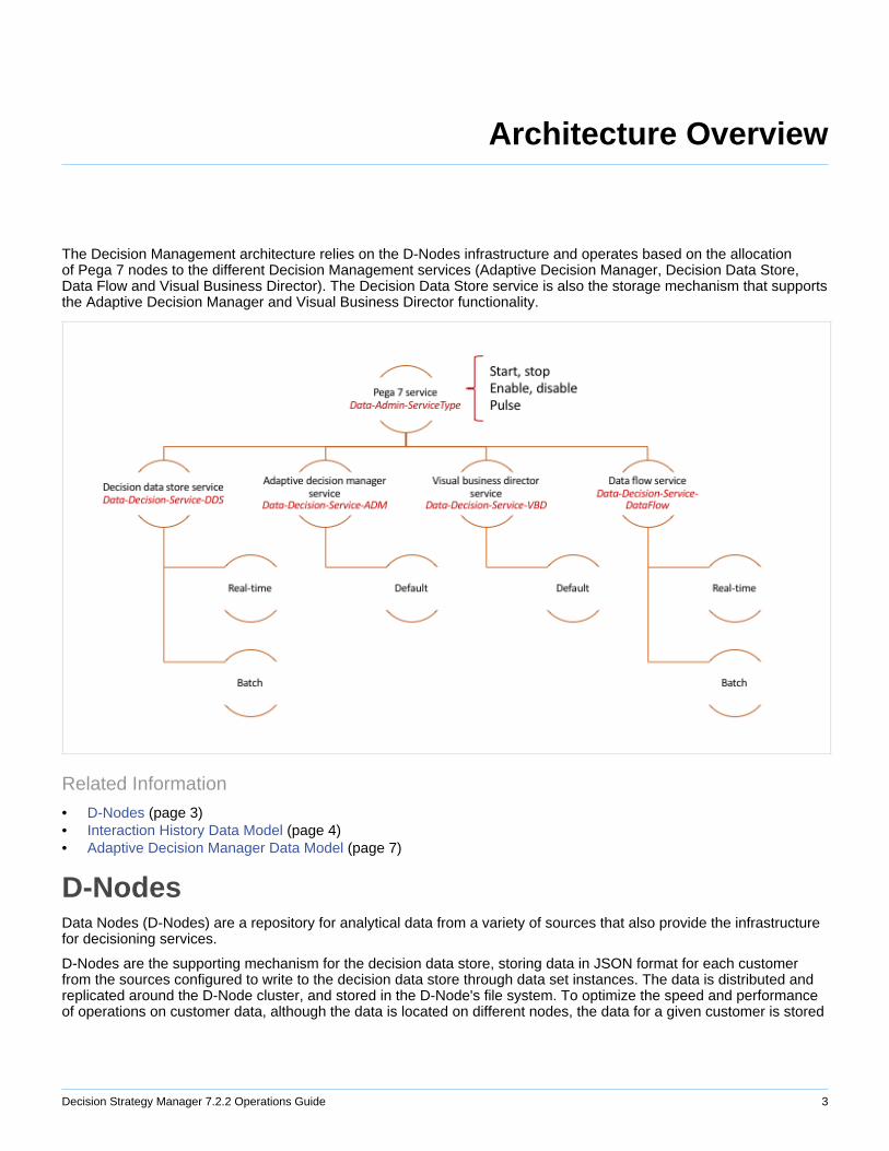
The Decision Management architecture relies on the D-Nodes infrastructure and operates based on the allocationof Pega 7 nodes to the different Decision Management services (Adaptive Decision Manager, Decision Data Store,Data Flow and Visual Business Director). The Decision Data Store service is also the storage mechanism that supportsthe Adaptive Decision Manager and Visual Business Director functionality.
Related Information
• D-Nodes (page 3)• Interaction History Data Model (page 4)• Adaptive Decision Manager Data Model (page 7)
D-NodesData Nodes (D-Nodes) are a repository for analytical data from a variety of sources that also provide the infrastructurefor decisioning services.
D-Nodes are the supporting mechanism for the decision data store, storing data in JSON format for each customerfrom the sources configured to write to the decision data store through data set instances. The data is distributed andreplicated around the D-Node cluster, and stored in the D-Node's file system. To optimize the speed and performanceof operations on customer data, although the data is located on different nodes, the data for a given customer is stored
Decision Strategy Manager 7.2.2 Operations Guide 4
on the same node. The decision data store differs from Interaction History in that it is not a stream of data over time,only the latest snapshot.
A D-Node consists of a standard Pega 7 installation augmented by a managed or an external Cassandra databaseprocess. D-Nodes rely on the Pega 7 clustering implementation and are capable of storing high volumes of data at highspeed. By creating a cluster of D-Nodes assigned to the applicable service, you can leverage Cassandra's attributes toprotect data from failure, as well as provide horizontal scalability. D-Nodes are capable of making specialized decisionsin real time, allowing you to take data from different sources that are continuously available (or not), and making itavailable for real time and batch processing. The embedded nature of the persistence solution means that it is alsooptimized for batch processing.
Interaction History Data Model• Database tables (page 4)• Properties (page 5)
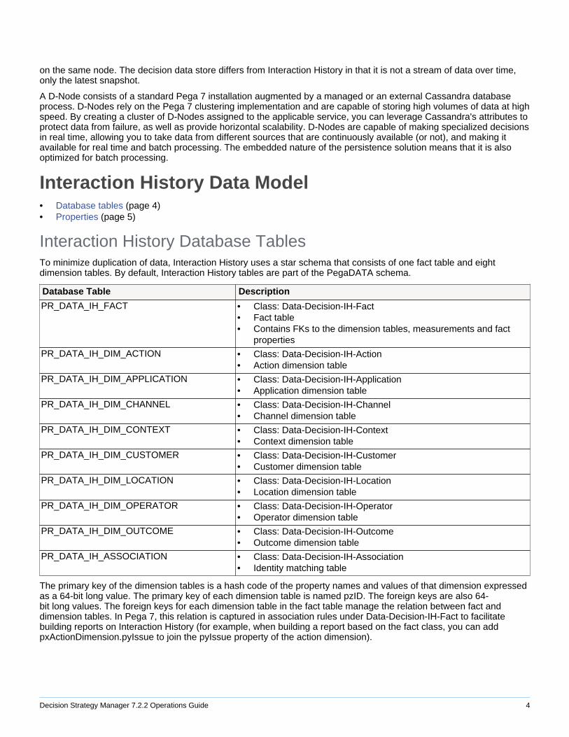
Interaction History Database TablesTo minimize duplication of data, Interaction History uses a star schema that consists of one fact table and eightdimension tables. By default, Interaction History tables are part of the PegaDATA schema.
Database Table Description
PR_DATA_IH_FACT • Class: Data-Decision-IH-Fact• Fact table• Contains FKs to the dimension tables, measurements and fact
properties
PR_DATA_IH_DIM_ACTION • Class: Data-Decision-IH-Action• Action dimension table
PR_DATA_IH_DIM_APPLICATION • Class: Data-Decision-IH-Application• Application dimension table
PR_DATA_IH_DIM_CHANNEL • Class: Data-Decision-IH-Channel• Channel dimension table
PR_DATA_IH_DIM_CONTEXT • Class: Data-Decision-IH-Context• Context dimension table
PR_DATA_IH_DIM_CUSTOMER • Class: Data-Decision-IH-Customer• Customer dimension table
PR_DATA_IH_DIM_LOCATION • Class: Data-Decision-IH-Location• Location dimension table
PR_DATA_IH_DIM_OPERATOR • Class: Data-Decision-IH-Operator• Operator dimension table
PR_DATA_IH_DIM_OUTCOME • Class: Data-Decision-IH-Outcome• Outcome dimension table
PR_DATA_IH_ASSOCIATION • Class: Data-Decision-IH-Association• Identity matching table
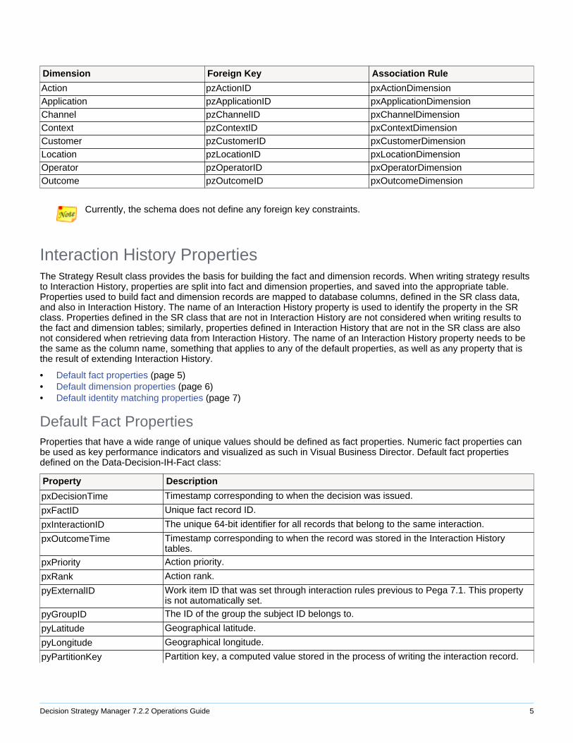
The primary key of the dimension tables is a hash code of the property names and values of that dimension expressedas a 64-bit long value. The primary key of each dimension table is named pzID. The foreign keys are also 64-bit long values. The foreign keys for each dimension table in the fact table manage the relation between fact anddimension tables. In Pega 7, this relation is captured in association rules under Data-Decision-IH-Fact to facilitatebuilding reports on Interaction History (for example, when building a report based on the fact class, you can addpxActionDimension.pyIssue to join the pyIssue property of the action dimension).
Decision Strategy Manager 7.2.2 Operations Guide 5
Dimension Foreign Key Association Rule
Action pzActionID pxActionDimensionApplication pzApplicationID pxApplicationDimensionChannel pzChannelID pxChannelDimensionContext pzContextID pxContextDimensionCustomer pzCustomerID pxCustomerDimensionLocation pzLocationID pxLocationDimensionOperator pzOperatorID pxOperatorDimensionOutcome pzOutcomeID pxOutcomeDimension
Currently, the schema does not define any foreign key constraints.
Interaction History PropertiesThe Strategy Result class provides the basis for building the fact and dimension records. When writing strategy resultsto Interaction History, properties are split into fact and dimension properties, and saved into the appropriate table.Properties used to build fact and dimension records are mapped to database columns, defined in the SR class data,and also in Interaction History. The name of an Interaction History property is used to identify the property in the SRclass. Properties defined in the SR class that are not in Interaction History are not considered when writing results tothe fact and dimension tables; similarly, properties defined in Interaction History that are not in the SR class are alsonot considered when retrieving data from Interaction History. The name of an Interaction History property needs to bethe same as the column name, something that applies to any of the default properties, as well as any property that isthe result of extending Interaction History.
• Default fact properties (page 5)• Default dimension properties (page 6)• Default identity matching properties (page 7)
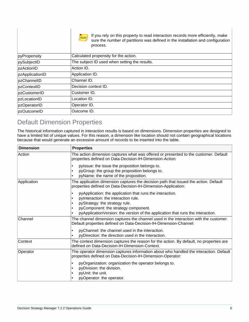
Default Fact PropertiesProperties that have a wide range of unique values should be defined as fact properties. Numeric fact properties canbe used as key performance indicators and visualized as such in Visual Business Director. Default fact propertiesdefined on the Data-Decision-IH-Fact class:
Property Description
pxDecisionTime Timestamp corresponding to when the decision was issued.
pxFactID Unique fact record ID.
pxInteractionID The unique 64-bit identifier for all records that belong to the same interaction.
pxOutcomeTime Timestamp corresponding to when the record was stored in the Interaction Historytables.
pxPriority Action priority.
pxRank Action rank.
pyExternalID Work item ID that was set through interaction rules previous to Pega 7.1. This propertyis not automatically set.
pyGroupID The ID of the group the subject ID belongs to.
pyLatitude Geographical latitude.
pyLongitude Geographical longitude.
pyPartitionKey Partition key, a computed value stored in the process of writing the interaction record.
Decision Strategy Manager 7.2.2 Operations Guide 6
If you rely on this property to read interaction records more efficiently, makesure the number of partitions was defined in the installation and configurationprocess.
pyPropensity Calculated propensity for the action.
pySubjectID The subject ID used when setting the results.
pzActionID Action ID.
pzApplicationID Application ID.
pzChannelID Channel ID.
pzContextID Decision context ID.
pzCustomerID Customer ID.
pzLocationID Location ID.
pzOperatorID Operator ID.
pzOutcomeID Outcome ID.
Default Dimension PropertiesThe historical information captured in interaction results is based on dimensions. Dimension properties are designed tohave a limited list of unique values. For this reason, a dimension like location should not contain geographical locationsbecause that would generate an excessive amount of records to be inserted into the table.
Dimension Properties
Action The action dimension captures what was offered or presented to the customer. Defaultproperties defined on Data-Decision-IH-Dimension-Action:
• pyIssue: the issue the proposition belongs to.• pyGroup: the group the proposition belongs to.• pyName: the name of the proposition.
Application The application dimension captures the decision path that issued the action. Defaultproperties defined on Data-Decision-IH-Dimension-Application:
• pyApplication: the application that runs the interaction.• pyInteraction: the interaction rule.• pyStrategy: the strategy rule.• pyComponent: the strategy component.• pyApplicationVersion: the version of the application that runs the interaction.
Channel The channel dimension captures the channel used in the interaction with the customer.Default properties defined on Data-Decision-IH-Dimension-Channel:
• pyChannel: the channel used in the interaction.• pyDirection: the direction used in the interaction.
Context The context dimension captures the reason for the action. By default, no properties aredefined on Data-Decision-IH-Dimension-Context.
Operator The operator dimension captures information about who handled the interaction. Defaultproperties defined on Data-Decision-IH-Dimension-Operator:
• pyOrganization: organization the operator belongs to.• pyDivision: the division.• pyUnit: the unit.• pyOperator: the operator.
Decision Strategy Manager 7.2.2 Operations Guide 7
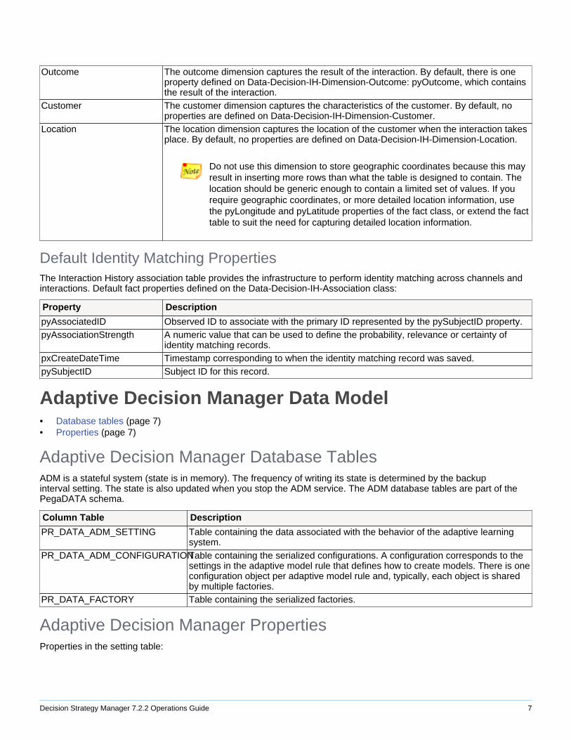
Outcome The outcome dimension captures the result of the interaction. By default, there is oneproperty defined on Data-Decision-IH-Dimension-Outcome: pyOutcome, which containsthe result of the interaction.
Customer The customer dimension captures the characteristics of the customer. By default, noproperties are defined on Data-Decision-IH-Dimension-Customer.
Location The location dimension captures the location of the customer when the interaction takesplace. By default, no properties are defined on Data-Decision-IH-Dimension-Location.
Do not use this dimension to store geographic coordinates because this mayresult in inserting more rows than what the table is designed to contain. Thelocation should be generic enough to contain a limited set of values. If yourequire geographic coordinates, or more detailed location information, usethe pyLongitude and pyLatitude properties of the fact class, or extend the facttable to suit the need for capturing detailed location information.
Default Identity Matching PropertiesThe Interaction History association table provides the infrastructure to perform identity matching across channels andinteractions. Default fact properties defined on the Data-Decision-IH-Association class:
Property Description
pyAssociatedID Observed ID to associate with the primary ID represented by the pySubjectID property.pyAssociationStrength A numeric value that can be used to define the probability, relevance or certainty of
identity matching records. pxCreateDateTime Timestamp corresponding to when the identity matching record was saved.pySubjectID Subject ID for this record.
Adaptive Decision Manager Data Model• Database tables (page 7)• Properties (page 7)
Adaptive Decision Manager Database TablesADM is a stateful system (state is in memory). The frequency of writing its state is determined by the backupinterval setting. The state is also updated when you stop the ADM service. The ADM database tables are part of thePegaDATA schema.
Column Table Description
PR_DATA_ADM_SETTING Table containing the data associated with the behavior of the adaptive learningsystem.
PR_DATA_ADM_CONFIGURATIONTable containing the serialized configurations. A configuration corresponds to thesettings in the adaptive model rule that defines how to create models. There is oneconfiguration object per adaptive model rule and, typically, each object is sharedby multiple factories.
PR_DATA_FACTORY Table containing the serialized factories.
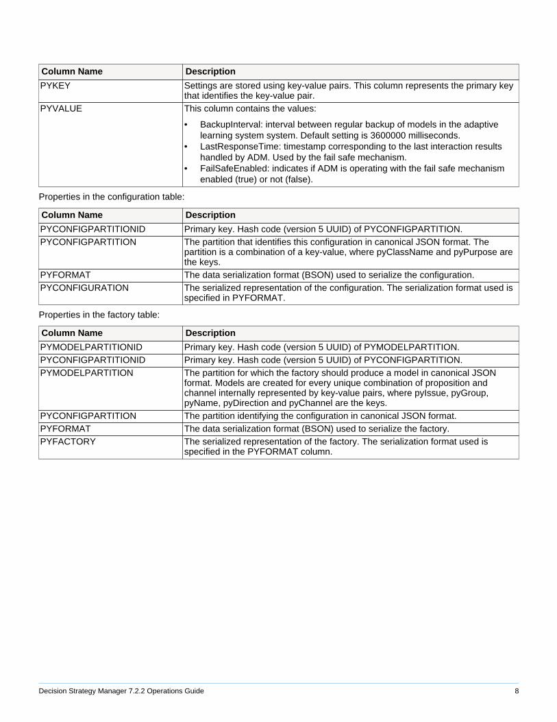
Adaptive Decision Manager PropertiesProperties in the setting table:
Decision Strategy Manager 7.2.2 Operations Guide 8
Column Name Description
PYKEY Settings are stored using key-value pairs. This column represents the primary keythat identifies the key-value pair.
PYVALUE This column contains the values:
• BackupInterval: interval between regular backup of models in the adaptivelearning system system. Default setting is 3600000 milliseconds.
• LastResponseTime: timestamp corresponding to the last interaction resultshandled by ADM. Used by the fail safe mechanism.
• FailSafeEnabled: indicates if ADM is operating with the fail safe mechanismenabled (true) or not (false).
Properties in the configuration table:
Column Name Description
PYCONFIGPARTITIONID Primary key. Hash code (version 5 UUID) of PYCONFIGPARTITION.PYCONFIGPARTITION The partition that identifies this configuration in canonical JSON format. The
partition is a combination of a key-value, where pyClassName and pyPurpose arethe keys.
PYFORMAT The data serialization format (BSON) used to serialize the configuration.PYCONFIGURATION The serialized representation of the configuration. The serialization format used is
specified in PYFORMAT.
Properties in the factory table:
Column Name Description
PYMODELPARTITIONID Primary key. Hash code (version 5 UUID) of PYMODELPARTITION.PYCONFIGPARTITIONID Primary key. Hash code (version 5 UUID) of PYCONFIGPARTITION.PYMODELPARTITION The partition for which the factory should produce a model in canonical JSON
format. Models are created for every unique combination of proposition andchannel internally represented by key-value pairs, where pyIssue, pyGroup,pyName, pyDirection and pyChannel are the keys.
PYCONFIGPARTITION The partition identifying the configuration in canonical JSON format.PYFORMAT The data serialization format (BSON) used to serialize the factory.PYFACTORY The serialized representation of the factory. The serialization format used is
specified in the PYFORMAT column.
Decision Strategy Manager 7.2.2 Operations Guide 9
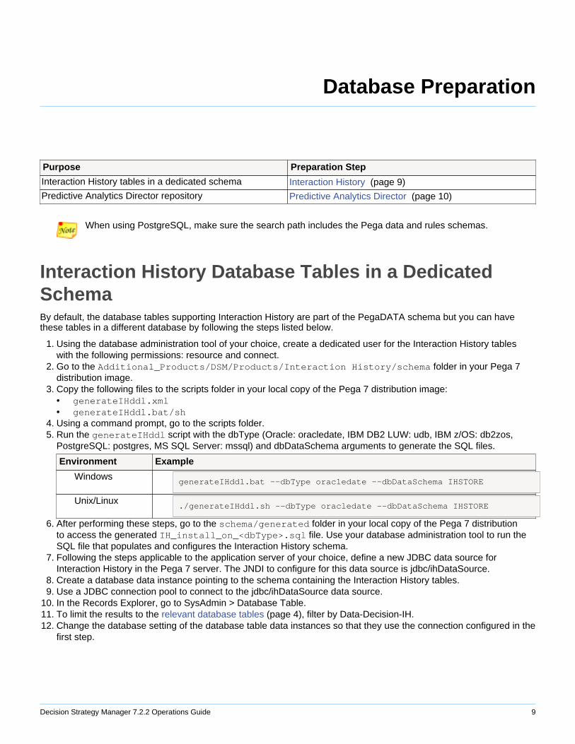
Database Preparation
Purpose Preparation Step
Interaction History tables in a dedicated schema Interaction History (page 9)
Predictive Analytics Director repository Predictive Analytics Director (page 10)
When using PostgreSQL, make sure the search path includes the Pega data and rules schemas.
Interaction History Database Tables in a DedicatedSchemaBy default, the database tables supporting Interaction History are part of the PegaDATA schema but you can havethese tables in a different database by following the steps listed below.
1. Using the database administration tool of your choice, create a dedicated user for the Interaction History tableswith the following permissions: resource and connect.
2. Go to the Additional_Products/DSM/Products/Interaction History/schema folder in your Pega 7distribution image.
3. Copy the following files to the scripts folder in your local copy of the Pega 7 distribution image:• generateIHddl.xml• generateIHddl.bat/sh
4. Using a command prompt, go to the scripts folder.5. Run the generateIHddl script with the dbType (Oracle: oracledate, IBM DB2 LUW: udb, IBM z/OS: db2zos,
PostgreSQL: postgres, MS SQL Server: mssql) and dbDataSchema arguments to generate the SQL files.
Environment Example
WindowsgenerateIHddl.bat --dbType oracledate --dbDataSchema IHSTORE
Unix/Linux./generateIHddl.sh --dbType oracledate --dbDataSchema IHSTORE
6. After performing these steps, go to the schema/generated folder in your local copy of the Pega 7 distributionto access the generated IH_install_on_<dbType>.sql file. Use your database administration tool to run theSQL file that populates and configures the Interaction History schema.
7. Following the steps applicable to the application server of your choice, define a new JDBC data source forInteraction History in the Pega 7 server. The JNDI to configure for this data source is jdbc/ihDataSource.
8. Create a database data instance pointing to the schema containing the Interaction History tables.9. Use a JDBC connection pool to connect to the jdbc/ihDataSource data source.
10. In the Records Explorer, go to SysAdmin > Database Table.11. To limit the results to the relevant database tables (page 4), filter by Data-Decision-IH.12. Change the database setting of the database table data instances so that they use the connection configured in the
first step.
Decision Strategy Manager 7.2.2 Operations Guide 10
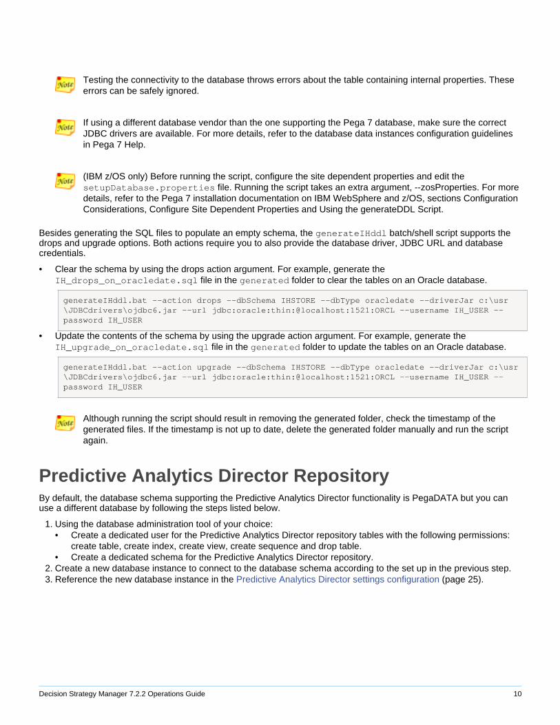
Testing the connectivity to the database throws errors about the table containing internal properties. Theseerrors can be safely ignored.
If using a different database vendor than the one supporting the Pega 7 database, make sure the correctJDBC drivers are available. For more details, refer to the database data instances configuration guidelinesin Pega 7 Help.
(IBM z/OS only) Before running the script, configure the site dependent properties and edit thesetupDatabase.properties file. Running the script takes an extra argument, --zosProperties. For moredetails, refer to the Pega 7 installation documentation on IBM WebSphere and z/OS, sections ConfigurationConsiderations, Configure Site Dependent Properties and Using the generateDDL Script.
Besides generating the SQL files to populate an empty schema, the generateIHddl batch/shell script supports thedrops and upgrade options. Both actions require you to also provide the database driver, JDBC URL and databasecredentials.
• Clear the schema by using the drops action argument. For example, generate theIH_drops_on_oracledate.sql file in the generated folder to clear the tables on an Oracle database.
generateIHddl.bat --action drops --dbSchema IHSTORE --dbType oracledate --driverJar c:\usr\JDBCdrivers\ojdbc6.jar --url jdbc:oracle:thin:@localhost:1521:ORCL --username IH_USER --password IH_USER
• Update the contents of the schema by using the upgrade action argument. For example, generate theIH_upgrade_on_oracledate.sql file in the generated folder to update the tables on an Oracle database.
generateIHddl.bat --action upgrade --dbSchema IHSTORE --dbType oracledate --driverJar c:\usr\JDBCdrivers\ojdbc6.jar --url jdbc:oracle:thin:@localhost:1521:ORCL --username IH_USER --password IH_USER
Although running the script should result in removing the generated folder, check the timestamp of thegenerated files. If the timestamp is not up to date, delete the generated folder manually and run the scriptagain.
Predictive Analytics Director RepositoryBy default, the database schema supporting the Predictive Analytics Director functionality is PegaDATA but you canuse a different database by following the steps listed below.
1. Using the database administration tool of your choice:• Create a dedicated user for the Predictive Analytics Director repository tables with the following permissions:
create table, create index, create view, create sequence and drop table.• Create a dedicated schema for the Predictive Analytics Director repository.
2. Create a new database instance to connect to the database schema according to the set up in the previous step.3. Reference the new database instance in the Predictive Analytics Director settings configuration (page 25).
Decision Strategy Manager 7.2.2 Operations Guide 11
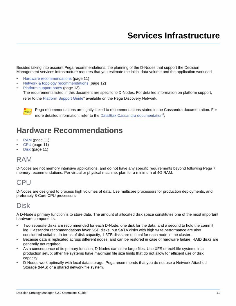
Services Infrastructure
Besides taking into account Pega recommendations, the planning of the D-Nodes that support the DecisionManagement services infrastructure requires that you estimate the initial data volume and the application workload.
• Hardware recommendations (page 11)• Network & topology recommendations (page 12)• Platform support notes (page 13)
The requirements listed in this document are specific to D-Nodes. For detailed information on platform support,
refer to the Platform Support Guide1 available on the Pega Discovery Network.
Pega recommendations are tightly linked to recommendations stated in the Cassandra documentation. For
more detailed information, refer to the DataStax Cassandra documentation2.
Hardware Recommendations• RAM (page 11)• CPU (page 11)• Disk (page 11)
RAMD-Nodes are not memory intensive applications, and do not have any specific requirements beyond following Pega 7memory recommendations. Per virtual or physical machine, plan for a minimum of 4G RAM.
CPUD-Nodes are designed to process high volumes of data. Use multicore processors for production deployments, andpreferably 8-Core CPU processors.
DiskA D-Node’s primary function is to store data. The amount of allocated disk space constitutes one of the most importanthardware components.
• Two separate disks are recommended for each D-Node: one disk for the data, and a second to hold the commitlog. Cassandra recommendations favor SSD disks, but SATA disks with high write performance are alsoconsidered suitable. In terms of disk capacity, 1-3TB disks are optimal for each node in the cluster.
• Because data is replicated across different nodes, and can be restored in case of hardware failure, RAID disks aregenerally not required.
• As a consequence of its primary function, D-Nodes can store large files. Use XFS or ext4 file systems in aproduction setup; other file systems have maximum file size limits that do not allow for efficient use of diskcapacity.
• D-Nodes work optimally with local data storage. Pega recommends that you do not use a Network AttachedStorage (NAS) or a shared network file system.
Decision Strategy Manager 7.2.2 Operations Guide 12
Network & Topology Recommendations• D-Node cluster (page 12)• Cluster sizing (page 13)• Network (page 13)• Network time protocol (page 13)
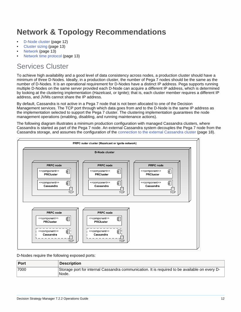
Services ClusterTo achieve high availability and a good level of data consistency across nodes, a production cluster should have aminimum of three D-Nodes. Ideally, in a production cluster, the number of Pega 7 nodes should be the same as thenumber of D-Nodes. It is an operational requirement for D-Nodes have a distinct IP address. Pega supports runningmultiple D-Nodes on the same server provided each D-Node can acquire a different IP address, which is determinedby looking at the clustering implementation (Hazelcast, or Ignite); that is, each cluster member requires a different IPaddress, and JVMs cannot share the IP address.
By default, Cassandra is not active in a Pega 7 node that is not been allocated to one of the DecisionManagement services. The TCP port through which data goes from and to the D-Node is the same IP address asthe implementation selected to support the Pega 7 cluster. The clustering implementation guarantees the nodemanagement operations (enabling, disabling, and running maintenance actions).
The following diagram illustrates a minimum production configuration with managed Cassandra clusters, whereCassandra is started as part of the Pega 7 node. An external Cassandra system decouples the Pega 7 node from theCassandra storage, and assumes the configuration of the connection to the external Cassandra cluster (page 18).
D-Nodes require the following exposed ports:
Port Description
7000 Storage port for internal Cassandra communication. It is required to be available on every D-Node.
Decision Strategy Manager 7.2.2 Operations Guide 13
7003 Default port for incoming stream communication. It is required to be available if using streamdata sets.
9042 CQL3 native transport port. It is required if the decision data store service uses an externalCassandra based on CQL3.
9160 Thrift RCP transport port. It is required if the decision data store service uses an externalCassandra based on Thrift.
5751 Communication port for the VBD instance. The port number is determined by the waythe VBD service is configured. By default, it is configured to require the 5751 port, but you canchange this setting, and it can also dynamically look for the exposed port if you configure thecluster port to auto-increment.
The Cassandra instance starts when you allocate the node to a service and on startup of a Pega 7 instance previouslyassigned to a service. The D-Node service listener is responsible for the bootstrap procedure. This listener is enabledby default, executed at server startup and can be monitored using the System Management Application. It performs aseries of operations to bootstrap the Cassandra engine:
1. Reading the Cassandra configuration as defined in the cassandra.yaml file.2. Reading the Pega 7 configuration as defined in the prconfig.xml file.3. Merging the Cassandra and Pega 7 configuration settings into a new cassandra.yaml file.4. Bootstrapping the Cassandra engine with the merged cassandra.yaml file.
Cluster SizingPega provides a sizing calculation tool in the form of an Excel spreadsheet that allows you to calculate the data sizerequirements. Use the following guidelines to estimate the number of required D-Nodes:
• Start with the recommended minimum amount of D-Nodes (three).• Compute the total required disk space and sum up the estimation for each decision data store type data set.
Use the D-Node Sizing Model spreadsheet for this purpose. Contact Pega Support for information on how to obtainthe D-Node Sizing Model spreadsheet.
• After dividing it by the number of available D-Nodes, make sure the total data size as calculated before remainswithin the 30-40% limit of available disk space for a single D-Node.
• If you use the cluster for simulations and data flow runs, add more nodes to the D-Node cluster to increaseprocessing speed.
Network• Use Gigabit Ethernet. Network bandwidth needs to be 1000 Mbit/s (gigabit), or greater.• Each D-Node requires a dedicated IP address. If multiple D-Nodes run on the same server, make sure each D-
Node has a different IP address.
Network Time ProtocolSynchronization is required between the clocks of Pega 7 nodes, server(s) hosting the application server and server(s)hosting the database. See also, Pega 7 Help, and search for "clusters (multiple-node nodes)" to find the Clusters -Concepts and terms topic.
D-Nodes Platform Support NotesFor detailed information on platform support, refer to the Platform Support Guide3 available on the Pega DiscoveryNetwork. This topic lists specific prerequisites notes for Pega 7 installations that run as D-Nodes.
• JVM version for Pega 7 installations running as D-Nodes:• Java 7 or higher• 64bit
Decision Strategy Manager 7.2.2 Operations Guide 14
• Standard JVM memory requirements:• 1024 initial Java heap size• 2048 maximum Java heap size
Stated memory settings are a generic indication. Consult the Cassandra DataStax documentation for more
details on how to tune Java resources4.• JMX needs to be configured at the application server level so that you can use the Cassandra nodetool utility and
Cassandra JMX endpoints.• A minimum configuration applies to user resources. Follow the DataStax recommendations to set the user
resource limits5.• The requirement Cassandra 2.1 applies when using external Cassandra cluster for the Decision Data Store
service.
Notes1. https://pdn.pega.com/documents/platform-support-guide
2. http://docs.datastax.com/en/cassandra/2.1/cassandra/architecture/architecturePlanningAbout_c.html
3. https://pdn.pega.com/documents/platform-support-guide
4. http://docs.datastax.com/en/cassandra/2.1/cassandra/operations/ops_tune_jvm_c.html
5. http://docs.datastax.com/en/cassandra/2.1/cassandra/troubleshooting/trblshootInsufficientResources_r.html
Decision Strategy Manager 7.2.2 Operations Guide 15
Configuration
• Service nodes (page 15)• Decision Management enabled applications (page 19)• Proposition cache synchronization (page 21)• Interaction History (page 21)• Batch simulations (page 23)• Visual Business Director (page 25)• Predictive Analytics Director settings (page 25)
Service Nodes• Pega 7 nodes (page 15)• Services infrastructure (page 16)
Pega 7 Nodes• Configuration settings (page 15)• Logging (page 15)
Configuration SettingsConfiguration settings can be applied through the prconfig.xml file. If applicable, you need to configure thesesettings individually for every node in the cluster.
Configuration Setting Description
dsm/services A comma separated list of values that configures the servicesoperating in the Pega 7 node, providing a method to automate themanual configuration done through the Services landing page. Thepossible values are DDS, DataFlow, ADM, and VBD.
dnode/yaml/commitlog_directory The directory where the D-Node commit log is stored. By default, it isassumed to be <workfolder>/<clustername>/commitlog.
dnode/yaml/data_file_directories The directory location where SSTables are stored. By default, it isassumed to be <workfolder>/<clustername>/data.
dnode/yaml/internode_compression By default, the traffic between D-Nodes is compressed. You needto turn off compression for PPC64 architecture CPUs or old Linuxdistributions where the Snappy compression library is unavailable.
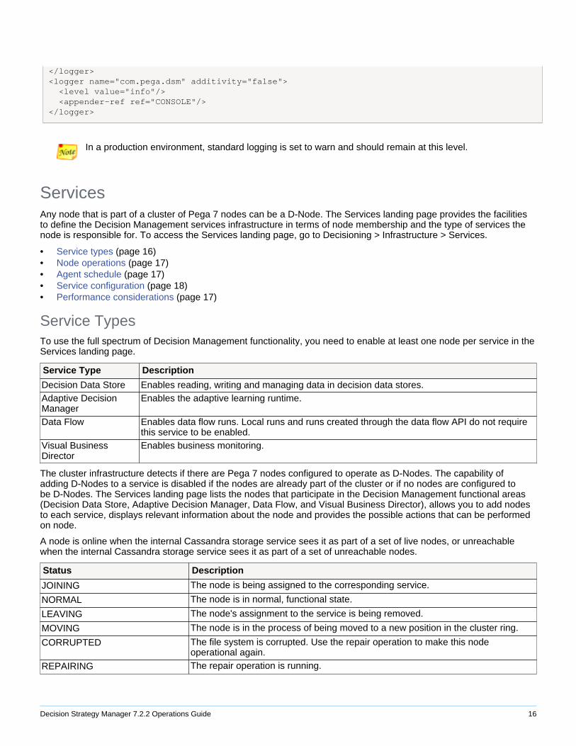
LoggingIn a development environment, you can enable Cassandra logging by adding the appropriate logger settings in theprlogging.xml file. In the example provided below, logging is set to show information messages for Cassandra andDecision Strategy Manager activity. You can control the level of logging by setting it to the another level. Refer to theApache Commons Logging documentation1 for more information on log levels.
<logger name="org.apache.cassandra" additivity="false"> <level value="info"/> <appender-ref ref="CONSOLE"/>
Decision Strategy Manager 7.2.2 Operations Guide 16
</logger><logger name="com.pega.dsm" additivity="false"> <level value="info"/> <appender-ref ref="CONSOLE"/></logger>
In a production environment, standard logging is set to warn and should remain at this level.
ServicesAny node that is part of a cluster of Pega 7 nodes can be a D-Node. The Services landing page provides the facilitiesto define the Decision Management services infrastructure in terms of node membership and the type of services thenode is responsible for. To access the Services landing page, go to Decisioning > Infrastructure > Services.
• Service types (page 16)• Node operations (page 17)• Agent schedule (page 17)• Service configuration (page 18)• Performance considerations (page 17)
Service TypesTo use the full spectrum of Decision Management functionality, you need to enable at least one node per service in theServices landing page.
Service Type Description
Decision Data Store Enables reading, writing and managing data in decision data stores.Adaptive DecisionManager
Enables the adaptive learning runtime.
Data Flow Enables data flow runs. Local runs and runs created through the data flow API do not requirethis service to be enabled.
Visual BusinessDirector
Enables business monitoring.
The cluster infrastructure detects if there are Pega 7 nodes configured to operate as D-Nodes. The capability ofadding D-Nodes to a service is disabled if the nodes are already part of the cluster or if no nodes are configured tobe D-Nodes. The Services landing page lists the nodes that participate in the Decision Management functional areas(Decision Data Store, Adaptive Decision Manager, Data Flow, and Visual Business Director), allows you to add nodesto each service, displays relevant information about the node and provides the possible actions that can be performedon node.
A node is online when the internal Cassandra storage service sees it as part of a set of live nodes, or unreachablewhen the internal Cassandra storage service sees it as part of a set of unreachable nodes.
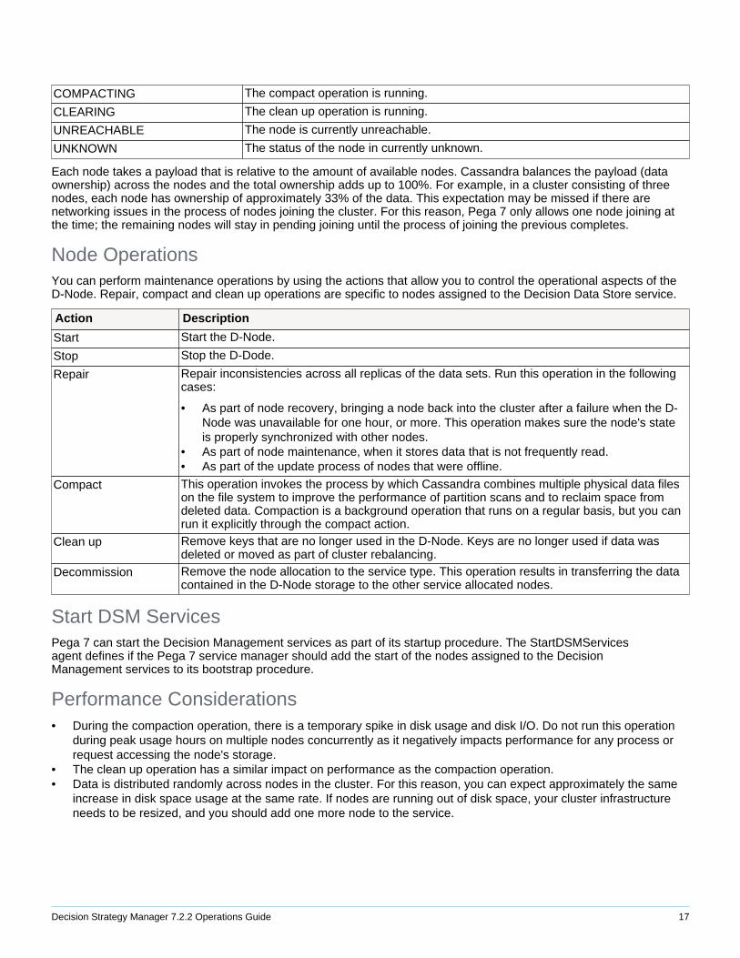
Status Description
JOINING The node is being assigned to the corresponding service.
NORMAL The node is in normal, functional state.
LEAVING The node's assignment to the service is being removed.
MOVING The node is in the process of being moved to a new position in the cluster ring.
CORRUPTED The file system is corrupted. Use the repair operation to make this nodeoperational again.
REPAIRING The repair operation is running.
Decision Strategy Manager 7.2.2 Operations Guide 17
COMPACTING The compact operation is running.
CLEARING The clean up operation is running.
UNREACHABLE The node is currently unreachable.
UNKNOWN The status of the node in currently unknown.
Each node takes a payload that is relative to the amount of available nodes. Cassandra balances the payload (dataownership) across the nodes and the total ownership adds up to 100%. For example, in a cluster consisting of threenodes, each node has ownership of approximately 33% of the data. This expectation may be missed if there arenetworking issues in the process of nodes joining the cluster. For this reason, Pega 7 only allows one node joining atthe time; the remaining nodes will stay in pending joining until the process of joining the previous completes.
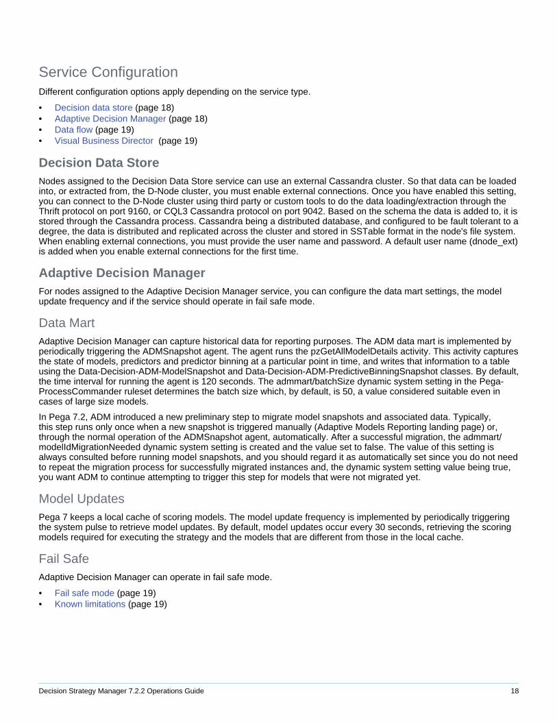
Node OperationsYou can perform maintenance operations by using the actions that allow you to control the operational aspects of theD-Node. Repair, compact and clean up operations are specific to nodes assigned to the Decision Data Store service.
Action Description
Start Start the D-Node.
Stop Stop the D-Dode.
Repair Repair inconsistencies across all replicas of the data sets. Run this operation in the followingcases:
• As part of node recovery, bringing a node back into the cluster after a failure when the D-Node was unavailable for one hour, or more. This operation makes sure the node's stateis properly synchronized with other nodes.
• As part of node maintenance, when it stores data that is not frequently read.• As part of the update process of nodes that were offline.
Compact This operation invokes the process by which Cassandra combines multiple physical data fileson the file system to improve the performance of partition scans and to reclaim space fromdeleted data. Compaction is a background operation that runs on a regular basis, but you canrun it explicitly through the compact action.
Clean up Remove keys that are no longer used in the D-Node. Keys are no longer used if data wasdeleted or moved as part of cluster rebalancing.
Decommission Remove the node allocation to the service type. This operation results in transferring the datacontained in the D-Node storage to the other service allocated nodes.
Start DSM ServicesPega 7 can start the Decision Management services as part of its startup procedure. The StartDSMServicesagent defines if the Pega 7 service manager should add the start of the nodes assigned to the DecisionManagement services to its bootstrap procedure.
Performance Considerations• During the compaction operation, there is a temporary spike in disk usage and disk I/O. Do not run this operation
during peak usage hours on multiple nodes concurrently as it negatively impacts performance for any process orrequest accessing the node's storage.
• The clean up operation has a similar impact on performance as the compaction operation.• Data is distributed randomly across nodes in the cluster. For this reason, you can expect approximately the same
increase in disk space usage at the same rate. If nodes are running out of disk space, your cluster infrastructureneeds to be resized, and you should add one more node to the service.
Decision Strategy Manager 7.2.2 Operations Guide 18
Service ConfigurationDifferent configuration options apply depending on the service type.
• Decision data store (page 18)• Adaptive Decision Manager (page 18)• Data flow (page 19)• Visual Business Director (page 19)
Decision Data StoreNodes assigned to the Decision Data Store service can use an external Cassandra cluster. So that data can be loadedinto, or extracted from, the D-Node cluster, you must enable external connections. Once you have enabled this setting,you can connect to the D-Node cluster using third party or custom tools to do the data loading/extraction through theThrift protocol on port 9160, or CQL3 Cassandra protocol on port 9042. Based on the schema the data is added to, it isstored through the Cassandra process. Cassandra being a distributed database, and configured to be fault tolerant to adegree, the data is distributed and replicated across the cluster and stored in SSTable format in the node's file system.When enabling external connections, you must provide the user name and password. A default user name (dnode_ext)is added when you enable external connections for the first time.
Adaptive Decision ManagerFor nodes assigned to the Adaptive Decision Manager service, you can configure the data mart settings, the modelupdate frequency and if the service should operate in fail safe mode.
Data MartAdaptive Decision Manager can capture historical data for reporting purposes. The ADM data mart is implemented byperiodically triggering the ADMSnapshot agent. The agent runs the pzGetAllModelDetails activity. This activity capturesthe state of models, predictors and predictor binning at a particular point in time, and writes that information to a tableusing the Data-Decision-ADM-ModelSnapshot and Data-Decision-ADM-PredictiveBinningSnapshot classes. By default,the time interval for running the agent is 120 seconds. The admmart/batchSize dynamic system setting in the Pega-ProcessCommander ruleset determines the batch size which, by default, is 50, a value considered suitable even incases of large size models.
In Pega 7.2, ADM introduced a new preliminary step to migrate model snapshots and associated data. Typically,this step runs only once when a new snapshot is triggered manually (Adaptive Models Reporting landing page) or,through the normal operation of the ADMSnapshot agent, automatically. After a successful migration, the admmart/modelIdMigrationNeeded dynamic system setting is created and the value set to false. The value of this setting isalways consulted before running model snapshots, and you should regard it as automatically set since you do not needto repeat the migration process for successfully migrated instances and, the dynamic system setting value being true,you want ADM to continue attempting to trigger this step for models that were not migrated yet.
Model UpdatesPega 7 keeps a local cache of scoring models. The model update frequency is implemented by periodically triggeringthe system pulse to retrieve model updates. By default, model updates occur every 30 seconds, retrieving the scoringmodels required for executing the strategy and the models that are different from those in the local cache.
Fail SafeAdaptive Decision Manager can operate in fail safe mode.
• Fail safe mode (page 19)• Known limitations (page 19)

Decision Strategy Manager 7.2.2 Operations Guide 19
Fail Safe ModeThe fail safe operational mode prevents data loss in case of service unavailability. This mode is configured by enablingthe fail safe mechanism. The pyADMFailSafeEnabled property reflects the configuration of the fail safe mode. Changesto this property are communicated every time model update runs. In fail safe mode:
• New models and associated response records are captured in the corresponding decision data stores through datasets: • The pzModelEventStore data set is responsible for writing the model event records. • The pzResponseEventStore data set is responsible for capturing the responses.
• When ADM comes back to normal operational mode, it proceeds to synchronizing the ADM database with themodel and response events based on the timestamp of the last known response and the entries in the Cassandraevent log. So that it remains manageable, the Cassandra event log is cleared after each backup–the backupmechanism clears all entries in the event log that are older than two hours.
Limitations
• Data loss can still happen for responses sent immediately after reading the staging table but before the client wasable to connect, and actually set the response in ADM.
• The solution does not include any monitoring or notification mechanism. Except for errors or warnings in the logfiles, there is no indication that the ADM service is not in normal mode.
• It is assumed the Decision Data Store service is always online and and in normal operational mode.
Data FlowFor nodes to participate in the pool used to distribute a data flow run, configure the number of threads for data flow runpurposes.
Visual Business DirectorThe configuration of the Visual Business Director service consists of:
• Defining the communication port for the VBD nodes. If set to auto-increment, the communication port is determinedby looking at the next higher number exposed port.
• Defining the batch size, in terms of records, to retrieve the actuals data source. • Defining the refresh rate of the VBD planner. • Defining the query timeout for client requests to the server.
Decision Management Enabled Applications• Application dependencies (page 19)• Organizational structure (page 20)• Work pool (page 20)• Access groups and operators (page 20)
Application DependenciesThe core Decision Management rulesets (Pega-DecisionEngine and Pega-DecisionArchitect) are part of thePegaRULES application. PegaDM provides the additional change management functionality.
Built on Application Description
PegaRULES Enterprise applications built on PegaRULES have access to the core runtime and design timeDecision Management functionality (rule types, landing pages, and operational configuration).PegaRULEs also includes the text analytics functionality (Pega-NLP ruleset), the predictiveanalytics functionality (Pega-DecisionScience ruleset) and the implementation supporting datasourced from Big Data stores (Pega-BigData ruleset).
Decision Strategy Manager 7.2.2 Operations Guide 20
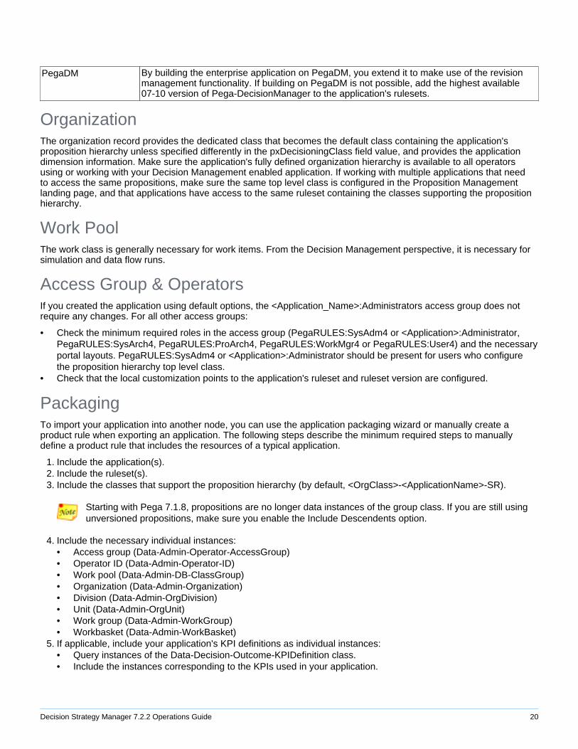
PegaDM By building the enterprise application on PegaDM, you extend it to make use of the revisionmanagement functionality. If building on PegaDM is not possible, add the highest available07-10 version of Pega-DecisionManager to the application's rulesets.
OrganizationThe organization record provides the dedicated class that becomes the default class containing the application'sproposition hierarchy unless specified differently in the pxDecisioningClass field value, and provides the applicationdimension information. Make sure the application's fully defined organization hierarchy is available to all operatorsusing or working with your Decision Management enabled application. If working with multiple applications that needto access the same propositions, make sure the same top level class is configured in the Proposition Managementlanding page, and that applications have access to the same ruleset containing the classes supporting the propositionhierarchy.
Work PoolThe work class is generally necessary for work items. From the Decision Management perspective, it is necessary forsimulation and data flow runs.
Access Group & OperatorsIf you created the application using default options, the <Application_Name>:Administrators access group does notrequire any changes. For all other access groups:
• Check the minimum required roles in the access group (PegaRULES:SysAdm4 or <Application>:Administrator,PegaRULES:SysArch4, PegaRULES:ProArch4, PegaRULES:WorkMgr4 or PegaRULES:User4) and the necessaryportal layouts. PegaRULES:SysAdm4 or <Application>:Administrator should be present for users who configurethe proposition hierarchy top level class.
• Check that the local customization points to the application's ruleset and ruleset version are configured.
PackagingTo import your application into another node, you can use the application packaging wizard or manually create aproduct rule when exporting an application. The following steps describe the minimum required steps to manuallydefine a product rule that includes the resources of a typical application.
1. Include the application(s).2. Include the ruleset(s).3. Include the classes that support the proposition hierarchy (by default, <OrgClass>-<ApplicationName>-SR).
Starting with Pega 7.1.8, propositions are no longer data instances of the group class. If you are still usingunversioned propositions, make sure you enable the Include Descendents option.
4. Include the necessary individual instances:• Access group (Data-Admin-Operator-AccessGroup)• Operator ID (Data-Admin-Operator-ID)• Work pool (Data-Admin-DB-ClassGroup)• Organization (Data-Admin-Organization)• Division (Data-Admin-OrgDivision)• Unit (Data-Admin-OrgUnit)• Work group (Data-Admin-WorkGroup)• Workbasket (Data-Admin-WorkBasket)
5. If applicable, include your application's KPI definitions as individual instances:• Query instances of the Data-Decision-Outcome-KPIDefinition class.• Include the instances corresponding to the KPIs used in your application.
Decision Strategy Manager 7.2.2 Operations Guide 21
Proposition Cache SynchronizationProposition cache works on a single Pega 7 node. Consistent handling of the proposition cache in a multinodeenvironment requires extra configuration.
• About proposition caching (page 21)• Configuring proposition cache synchronization (page 21)
About Proposition CachingWhen Pega 7 is running on multiple system nodes connected to the same database, Decision Management usesthe system pulse to ensure the consistency of propositions across all nodes. The proposition cache is invalidatedwhen a proposition is added, changed or deleted. Adding records that result in the proposition cache to becomeinvalid is done through two declare trigger rules that run the pyRefreshPropositions activity: pyPropositionSaved andpyPropositionRemoved.
Configuring Proposition Cache SynchronizationIf your installation consists of different Pega 7 nodes connected to the same database, you need to configure yourPega 7 installation to ensure the consistency of propositions across all nodes. System architects can follow these stepsto enable Pega 7 to work with the proposition cache synchronization mechanism:
1. In the Designer Studio menu, go to System > General.2. In the Systems, Nodes & Requestors landing page, locate the BATCH requestor type for the system name.3. Add the PegaDM:Administrators access group.4. Save the BATCH requestor type.
Assuming that all nodes of a cluster are on the same network, you only need to perform this configuration inone node.
Interaction History• Interaction History partitions (page 21)• Interaction History (page 21) extension (page 21)
Interaction History PartitionsTo optimize retrieving and reading records stored in the Interaction History table, the pxInteractionHistory data set candistribute read operations across nodes by using the pyPartitionKey property (page 5). This value is computed basedon the interactionHistory/numberOfPartition dynamic system setting. Pega recommends that you set this value to thedouble of available virtual CPUs. For example, if the number of virtual CPUs is eight, you should configure the numberof partitions to be 16.
Interaction History ExtensionInteraction History's extension model is database driven. Case sensitive name matching is used between properties inthe database table, SR properties and Interaction History properties. Typically, the same Interaction History is used bymultiple applications using a shared implementation. You can extend Interaction History with new properties. Numericproperties in the Interaction History's fact table can be used as key performance indicators (KPIs), in which case it isrecommended that you use values that can be summed up so that the property can be used as a KPI.
• Interaction History configuration (page 22)• Extending Interaction History (page 22)• Excluding properties (page 23)
Decision Strategy Manager 7.2.2 Operations Guide 22
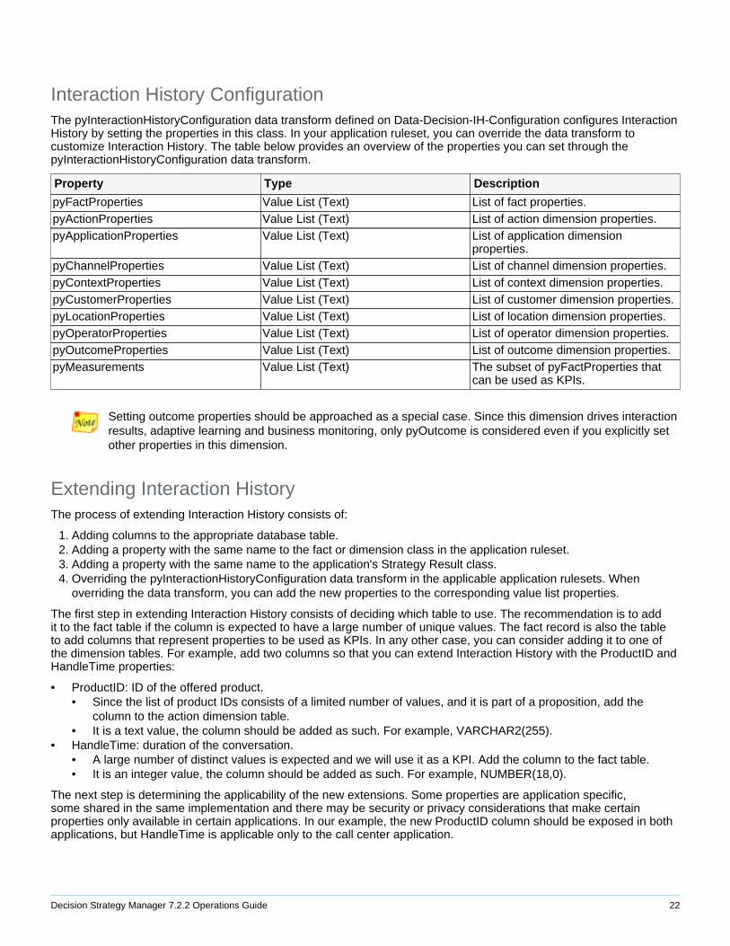
Interaction History ConfigurationThe pyInteractionHistoryConfiguration data transform defined on Data-Decision-IH-Configuration configures InteractionHistory by setting the properties in this class. In your application ruleset, you can override the data transform tocustomize Interaction History. The table below provides an overview of the properties you can set through thepyInteractionHistoryConfiguration data transform.
Property Type Description
pyFactProperties Value List (Text) List of fact properties.pyActionProperties Value List (Text) List of action dimension properties.pyApplicationProperties Value List (Text) List of application dimension
properties.pyChannelProperties Value List (Text) List of channel dimension properties.pyContextProperties Value List (Text) List of context dimension properties.pyCustomerProperties Value List (Text) List of customer dimension properties.pyLocationProperties Value List (Text) List of location dimension properties.pyOperatorProperties Value List (Text) List of operator dimension properties.pyOutcomeProperties Value List (Text) List of outcome dimension properties.pyMeasurements Value List (Text) The subset of pyFactProperties that
can be used as KPIs.
Setting outcome properties should be approached as a special case. Since this dimension drives interactionresults, adaptive learning and business monitoring, only pyOutcome is considered even if you explicitly setother properties in this dimension.
Extending Interaction HistoryThe process of extending Interaction History consists of:
1. Adding columns to the appropriate database table.2. Adding a property with the same name to the fact or dimension class in the application ruleset.3. Adding a property with the same name to the application's Strategy Result class.4. Overriding the pyInteractionHistoryConfiguration data transform in the applicable application rulesets. When
overriding the data transform, you can add the new properties to the corresponding value list properties.
The first step in extending Interaction History consists of deciding which table to use. The recommendation is to addit to the fact table if the column is expected to have a large number of unique values. The fact record is also the tableto add columns that represent properties to be used as KPIs. In any other case, you can consider adding it to one ofthe dimension tables. For example, add two columns so that you can extend Interaction History with the ProductID andHandleTime properties:
• ProductID: ID of the offered product.• Since the list of product IDs consists of a limited number of values, and it is part of a proposition, add the
column to the action dimension table.• It is a text value, the column should be added as such. For example, VARCHAR2(255).
• HandleTime: duration of the conversation.• A large number of distinct values is expected and we will use it as a KPI. Add the column to the fact table.• It is an integer value, the column should be added as such. For example, NUMBER(18,0).
The next step is determining the applicability of the new extensions. Some properties are application specific,some shared in the same implementation and there may be security or privacy considerations that make certainproperties only available in certain applications. In our example, the new ProductID column should be exposed in bothapplications, but HandleTime is applicable only to the call center application.

Decision Strategy Manager 7.2.2 Operations Guide 23
• To extend Interaction History with the ProductID property for all applications in the action dimension table:• Add a new property ProductID of type text to the Data-Decision-IH-Dimension-Action data model in the
application rulesets of the call center and the outbound marketing applications.• Add the ProductID property (same name and data type) to the Strategy Result class of both applications.• Override the pyInteractionHistoryConfiguration data transform in Data-Decision-IH-Configuration for both
application rulesets.• Add a new set action and set Primary.pyActionProperties(<APPEND>) to "ProductID". • Enable the call superclass data transform setting to make sure the default configuration is included.
• To extend Interaction History with the HandleTime property for the call center application in the fact table:• Add a new property HandleTime of type integer to the Data-Decision-IH-Fact data model in the application
ruleset of the call center application.• Add the HandleTime property (same name and data type) to the SR class of the call center application.• Override the pyInteractionHistoryConfiguration data transform in Data-Decision-IH-Configuration for the call
center ruleset.• Add a new set action and set Primary.pyFactProperties(<APPEND>) to "HandleTime". • Add another set action and set Primary.pyMeasurements(<APPEND>) to "HandleTime". This step is
necessary so that you can use it as a KPI.• Enable the call superclass data transform setting.
If the new properties are not recognized, save the corresponding database table rules, log out and log inagain.
Excluding PropertiesTo prevent issues with loading or saving instances the class, if you add a property to the fact or dimension classes butthis property is not to be considered part of Interaction History, configure the property's persistence settings so that itdoes not save property data.
Batch Simulations• Topology configuration (page 23)• ProcessBatchJob agent (page 24)• Dynamic system settings (page 24)
Starting with Pega 7.2.1, Pega is deprecating batch simulations in favor of batch data flow runs. Althoughyou can run existing simulations, you cannot create new ones.
TopologyIn distributed data flow or simulation runs, the topology configuration determines how many nodes participate in thepool used to distribute the run and the number of threads per node.
• Thread pool size (page 23)• Simulation runs (page 24)
Thread Pool SizeThe number of threads is determined by the agent/threadpoolsize and services/maxrequestorchildren environmentsettings. For example, you can select up to ten threads assuming the following configuration in the prconfig.xmlfile:
<env name="agent/threadpoolsize" value="10" />
Decision Strategy Manager 7.2.2 Operations Guide 24
<env name="services/maxrequestorchildren" value="10" />
Simulation RunsFor nodes to participate in the pool used to distribute a simulation run, make sure the ProcessBatchJob agent (page24) is running in the system node. The ProcessBatchJob agent reserves one thread for creating and waiting forrequests; the number of threads should be the number of threads for simulation work purposes, plus one (the standardthread that is reserved by the agent).
ProcessBatchJob AgentLarge scale simulation runs can execute across system nodes. This functionality requires extra configuration.
• About large scale simulations (page 24)• Configuring large scale simulations (page 24)
About Large SimulationsThe assignment, queuing and management of large scale simulations is governed by the ProcessBatchJob agentconfiguration. The agent is scheduled to run with a given regularity (in seconds) to trigger checking assignments in [email protected] workbasket. If there are assignments, they will be queued to create threads based on thethread configuration for each node. The status of the work item is updated as it progresses in this process and you canmonitor the assignment by viewing the instances in the workbasket.
Configuring Large Scale SimulationsSo that you can enable large scale simulation runs, configure the ProcessBatchJob agent in your ruleset.
1. If the agents rule instance is not present in your application's ruleset, create one.2. In the Schedule tab, add the ProcessBatchJob agent with the following settings:
• Agent Name: ProcessBatchJob• Pattern: Periodic• Interval: for example, 5• Enabled: check this option• Class: Data-Decision-StrategyExecution-BatchAgent• Activity Name: pzIntializeProcessEngine
3. In the Security tab, enable the Bypass activity authentication option and configure the application specific accessgroup.
4. Use SMA to make sure the agent is running.5. Configure the number of threads that can run in each node in the batch topology landing page.
Dynamic System SettingsIf the default system behavior that determines the transition of work items corresponding to simulation runs to resolved-failed status needs to be changed, add the corresponding system settings and set the value to the desired time intervalin minutes.
• By default, work items in open-running status without any progress for five minutes are set to resolved-failed.Default system behavior can be modified by adding the dsm/batch/autoRecoveryTimeForOpenRunningStatusdynamic system setting owned by Pega-DecisionEngine and configuring it with the desired value (for example, 10).
• By default, work items in pending-scheduled status for 30 minutes are set to resolved-failed. Default systembehavior can be modified by adding the dsm/batch/autoRecoveryTimeForPendingStatus dynamic system settingowned by Pega-DecisionEngine and configuring it with the desired value (for example, 60).
Decision Strategy Manager 7.2.2 Operations Guide 25
Visual Business DirectorWhen you open the VBD planner, the pyGetConfiguration activity under Data-Decision-VBD-Configuration gathersthe information required to render the VBD planner. This information (dimensions, properties and KPIs) is retrievedfrom Interaction History and forms the basis for visualizing decision results. To make sure that VBD is using the latestInteraction History configuration (actuals), run the pzUpdateActualsConfiguration activity under Data-Decision-VBD-Configuration to update the VBD server.
The pyGetDimensions activity under Data-Decision-VBD-DimensionDefinition provides a number of customizationpoints. The description of the property that represents the dimension determines the labels in the VBD planner. To usea different value, you can change the description of the corresponding property under Data-Decision-IH-Dimension-<DimensionName>. You can also do it by overriding the pyGetDimensions activity and changing the correspondingdimension's pyLabel. It is possible to customize how dimensions are displayed in the VBD planner by overriding thepyGetDimensions activity. You can change the default level by setting the dimension's pyDefaultLevel to another level.You can also provide a different sequence of properties for a given dimension by setting the pyLevels value list.
Predictive Analytics Director SettingsThe Predictive Analytics Director settings landing page provides the global settings that apply to the PredictiveAnalytics Director functionality.
• Entitled to use outcome inferencing: when enabled, you can create predictions with additional data analysis steps,allowing you to develop models that handle unknown behavior.
• Select internal database: the database used for the Predictive Analytics Director repository. By default, thePegaDATA database supports this repository, but you can change it to use a dedicated database.
Because the settings modified through this landing page apply to any operator using the portal, make sure youmodify Predictive Analytics Director settings when there are no operators actively using the Predictive AnalyticsDirector portal. Failing to do this means that portal users can experience unexpected behavior and projectinconsistencies.
Notes1. http://commons.apache.org/logging/guide.html#Message%20Priorities/Levels
Decision Strategy Manager 7.2.2 Operations Guide 26
Operational Guidelines
• Optimization (page 26)• Monitoring (page 26)• Node repair (page 26)• Node recovery (page 26)• Data backup and restore (page 27)• Disk space (page 27)• Troubleshooting (page 27)
OptimizationAlthough requiring administration to optimize its operations, Cassandra is largely self-managing. The servicesconfiguration (page 16) provides an overview of nodes assigned to each services, and allows you to perform to themost important optimization operations:
• Adding a new node.• Decommissioning an existing node.• Repairing inconsistencies across all replicas of the data sets.• Compacting data files.
Some of these operations cannot be performed automatically because, although they do not impact service availability,they significantly slow down system performance by 20-30%. For this reason, Pega recommends that you schedulerunning these operations in low-usage hours.
MonitoringCassandra exposes management operations via JMX. The D-Node makes these operations accessible to systemadministrators and external tools. The Cassandra nodetool utility1 allows you to manage and monitor a cluster, runcommands in order to view detailed metrics for tables, servers, network/disk/CPU utilization and read/write latencyhistograms. Monitoring tools (such as, DataStax OPSCenter, Nagios, or Monit) can be easily configured to monitor theservices infrastructure.
Node RepairIf all nodes in the services infrastructure are always available, you do not need to run repair operations. However,the reality is that nodes go down for one reason or another (for example, maintenance, hardware failures, or networkissues). The node repair operation makes data on a replica consistent with data on other nodes. This operation can betriggered by running the available actions for nodes assigned to the applicable part of the services infrastructure (page16) or by using the Cassandra nodetool utility. The following recommendations apply:
• Schedule repairs weekly.• Run repair when a node comes back after being unavailable for more than one hour.• Repair is a very I/O intensive operation and has to be scheduled in low-usage hours.
Node RecoveryRecommended node recovery procedure in case a node becomes unavailable and cannot be started anymore:
Decision Strategy Manager 7.2.2 Operations Guide 27
1. Decommission the failed node by using the corresponding action in the applicable area of the servicesinfrastructure (page 16) or by using the Cassandra nodetool utility.
2. Fix the source of the failure (for example, replace failed hardware parts or the entire node).3. Recover data.
• If the data was previously owned by the failed node and is available on replica nodes, drop the Cassandracommit log and data folders.
• If the data was previously owned by the failed node and is not available on any replica node, perform datarecovery from backup.
4. Start the node and add it back to the applicable service.5. To remove unused key ranges, run the cleanup operation on all nodes assigned to the Decision Management
services.Although not mandatory, this last step is highly recommended.
Data Backup & RestoreCassandra performs data backup by taking a snapshot of all on-disk data files (the SSTable files) stored in the datadirectory. While the system is online, you can take a snapshot of all keyspaces, a single keyspace, or a single table.Using a parallel ssh tool (for example, pssh), you can take a snapshot of the entire cluster, providing an eventuallyconsistent backup.
• Use the Cassandra nodetool utility to create and restore backups.• Data backup operations can be scheduled to run automatically.
Disk SpaceOne single D-Node running out of disk space does not affect the service availability, but the performance degrades andeventually a failure can occur. To avoid this situation, the following recommendations apply:
• D-Nodes should all have the same disk capacity (page 11).• Use standard server monitoring tools to check disk usage.• Take action if the server monitoring tool alerts about 70-80% percent of disk space usage.
Disk space can be extended by adding more nodes to the services or by adding more disk space. To add more diskspace, you bring down the node, replace/expand the existing disk and start the node. These operations do not result inservice outage as long as performed in time to avoid failures.
TroubleshootingLog entries allow you to debug D-Nodes operations by setting com.pega.dsm.dnode.impl.cassandra.Cassandra toDEBUG.
A successful start of the D-Node logs the following debug statement:
DNode finished bootstrapping
If Cassandra starts with corrupted SSTables, the log shows the following information statement:
Failed to start Cassandra. Corrupted SSTables: <CorruptSSTableException>
If the D-Node was added through the Services landing page, the following exception is displayed for nodes with anexception at start up:
Unable to enable as DNode
If the start of the D-Node fails due to an exception, the following error statement will be logged:
Decision Strategy Manager 7.2.2 Operations Guide 28
Cannot initialize DNode context and start Cassandra, PRPC continuing as non-DNode
An exception is logged if Snappy Compression support is unavailable in the platform. To address it, install Snappycompression or disable compression (page 15).
java.lang.NoClassDefFoundError: org.xerial.snappy.Snappy (initialization failure)
Data ownership is evenly distributed across the number of nodes, adding up to 100%. If data ownership is incorrectafter adding a node, you will need to perform a known sequence of steps; simply restarting the node is insufficient.You can check the data ownership through the node information, as provided in the applicable area of the servicesinfrastructure (page 16).
1. Decommission the node.2. Stop the node.3. Remove the Cassandra data files. The location of the data files is defined by the data_files_directories parameter
(page 15).4. Restart the node.5. Assign the node to the applicable service.
Notes1. http://docs.datastax.com/en/cassandra/2.1/cassandra/tools/toolsNodetool_r.html