Embed Size (px)
Citation preview

200406INK017U
For safe operation, be sure to read this OPERATION MANUAL thoroughly before using the pump to understand the “Warnings and Cautions” particularly. Be sure to keep this OPERATION MANUAL handy for future reference.
WARNING
YAMADA AMERICA, INC. 1200 NUCLEAR DRIVE WEST CHICAGO, ILLINOIS 60185 PHONE: 1-630-231-4083 FREE: 1-800-990-7867 FAX: 1-630-231-7405
Manufactured by YAMADA CORPORATION
INTERNATIONAL DEPARTMENT 1-1-3 MINAMI-MAGOME OHTA-KU, TOKYO 143-8504, JAPAN PHONE: (81) 3-3777-0241 FAX: (81) 3-3777-0584
Doc.No. INK 017 U-00
(DRUM TYPE INK SUPPLY PUMP)
Type: 200 25:1 Model No. 881032 Type: 250 20:1 Model No. 881033
OPERATION MANUAL

1
DRUM TYPE INK SUPPLY PUMP (TYPE 200, 250) Model 881032, 881033
CONTENTS
Contents...........................................................................1 Introduction ......................................................................1 For Safe Operation ..........................................................1 Warning and Cautions......................................................1 Operating Cautions ..........................................................2
1. Purpose .......................................................................3 2. Name of Each Part ......................................................3 3. Operation Mechanism .................................................3 4. Preparations before operating the pump
4.1 Selecting the appropriate installation place ...........4 4.2 Fixing the lift base..................................................4 4.3 Connecting to the ink delivery pipe........................4 4.4 Connecting to the air pipe......................................4 4.5 Adjusting the air pressure that operates the lift......4 4.6 Positioning the drum..............................................5 4.7 Adjusting the position of the lower limit switch.......5 4.8 Filling the oil container...........................................6 4.9 Preparation of an ink drum ....................................6 4.10 Setting the ink drum.............................................7 4.11 Sucking ink and removing air...............................7 4.12 Adjusting the pressure that operates the pump ...8 4.13 Cleaning the inside of the oil container and
replacing solvent.................................................8 4.14 Maintenance and inspection ................................8
5. Troubleshooting...........................................................9 6. Specifications ..............................................................10
Materials......................................................................10 Appearance and dimensions .......................................10 Performance curve ......................................................11 Life of expendable items..............................................11
7. Exploded View and Parts List 881032, 881033 Ink Supply Pump...............................12 803794 Inductor Plate Assembly .................................13 853773 Drum Lift Assembly.........................................14 804360 Operation Panel Assembly .............................15 804361 Tubing System................................................16
8. Limited warranty .....................................................END
− Introduction This OPERATION MANUAL describes the correct operation procedures and contains notes on usage, so that you can operate this pump effectively without any problems. Do not operate this pump before reading this manual. Be sure to read all of the warnings and cautions. Keep this manual handy for future reference. If you have any questions on the operation of this pump or if the pump operates improperly, contact your dealer or our office (see back page of this manual for our contact information).
◊ If your manual is damaged or lost, additional copies may be purchased from your dealer, or from Yamada directly.
− For Safe Operation
This document describes the items that are necessary to operate this product safety, correctly, and efficiently. Before operating this product, read this manual thoroughly, in particular the “Warnings and Cautions” section at the beginning of the manual. Store this manual in an easy-to-access place so that the user may refer to it whenever necessary.
− Warnings and Cautions For safe use of this product, be sure to note the following: In this document, warnings and cautions are indicated by symbols. These symbols are for those who will operate this product and for those who will be nearby, for safe operation and the prevention of personal injury and/or property damage. The following warning and caution symbols are described below.
If you ignore the warning described and operate the product in an improper manner, there is danger of serious bodily injury or death.
If you ignore the caution described and operate the product in an improper manner, there is danger of personal injury or property damage.
WARNING
CAUTION

2
DRUM TYPE INK SUPPLY PUMP (TYPE 200, 250) Model 881032, 881033
− Operating Cautions For safe use of the pump, be sure to follow the warnings and cautions described below.
CAUTION [Usage - environment and conditions] - For safe operation, read and understand all cautions
described in this manual thoroughly before operating the pump.
- An operator or maintenance person has to read this manual thoroughly until he/she is familiar with it before operating or performing maintenance of the pump and/or related pump(s).
- If you happen to lose or damage this manual, order it from your dealer or our office.
[On installation and piping] - If you detect any danger or any problem while operating
the pump, stop operating the pump, and then recover it from the dangerous or error condition.
- Before maintenance operation, be sure to stop air from being supplied to the pump, and release the internal pressure (imposed on air and any other fluid) of the pump.
- Carefully install only pipes whose material and size are appropriate as instructed in the “Cautions” so that no air/fluid can leak and no pipe can be damaged.
[When you do not use the pump or store it] - If the pump is left unused for a long time (a week or
longer), remove all fluid from the pump, clean it, and release the internal pressure of the air pipes and fluid hoses.
WARNING [On operation] - An operator or maintenance person has to read this
manual thoroughly until he/she is familiar with it before operating or performing maintenance of the pump and/or related pump(s).
[On installation]
- Use six lift base fixing holes to fix the lift with the anchors securely. If you do not fix the lift in this manner, the lift may fall down and cause injury or damage to the pump itself.
- If you do not use the pump as instructed in this manual or in accordance to the specifications, it may cause injury or damage to the pump itself.
[On disassemble, maintenance and inspection] - If you remodel the pump, it may cause injury or may
cause the pump to malfunction. Never remodel the pump. It is very dangerous.
- If you perform the maintenance operation of the pump while air is being supplied to the pump, fluid may gush out along with air. Before maintenance operation, be sure to stop air supply, stop the pump and release the internal pressure (imposed on air and fluid) of the pump.
- Fluid released form the pump may be hazardous to humans. Do not discharge such fluid to the ground directly, but put fluids into a dedicated container.
[On lifetime of consumable parts] - The lifetime of each consumable part varies depending
on the type of fluid you use and the pump operation condition. If the regulated performance decreases greatly, replace the part(s) with a new one(s).

3
Air motor
Lower pump
Piston
Connection rod
DRUM TYPE INK SUPPLY PUMP (TYPE 200, 250) Model 881032, 881033
1. Purpose This pump is a device for a 200-kg drum and consists of the compressed-air-driven lift on which the air-powered pump is attached. It is optimal for flowing and supplying ink with compressed air. This pump is designed to supply various places of a factory with ink through pipes and/or hoses. You can, therefore, obtain ink as desired by only operating the outlet valve at the workplace. 2. Name of Each Part
3. Operation Mechanism The Yamada air-powered pump is a reciprocate type pump that is driven by the compressed air. As shown in the figure to the top, this pump consists of the air motor section that drives the pump and the lower pump section that pumps up fluid. When the compressed air is supplied from the compressor to the air motor, the air piston starts moving up and down depending on the operation of the air switching mechanism built into the air piston itself. Movement of the air piston is conveyed to the piston of the lower pump via the joint rod that connects the air piston of the air motor and that of the lower pump to generate a reciprocal movement: up and down. Up/down movements of the lower pump cause fluid to be sucked up into the lower pump, and then released from the discharge port by the compressed air.
4
DRUM TYPE INK SUPPLY PUMP (TYPE 200, 250) Model 881032, 881033
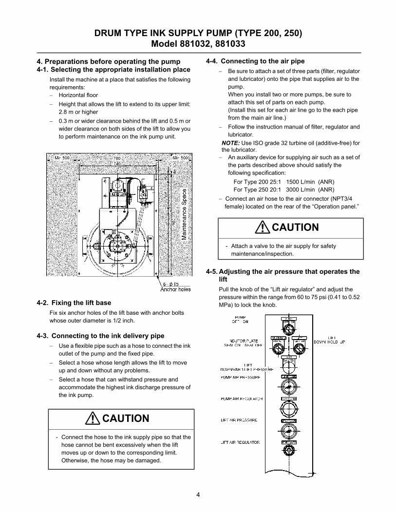
4. Preparations before operating the pump 4-1. Selecting the appropriate installation place
Install the machine at a place that satisfies the following requirements: − Horizontal floor − Height that allows the lift to extend to its upper limit:
2.8 m or higher − 0.3 m or wider clearance behind the lift and 0.5 m or
wider clearance on both sides of the lift to allow you to perform maintenance on the ink pump unit.
4-2. Fixing the lift base Fix six anchor holes of the lift base with anchor bolts whose outer diameter is 1/2 inch.
4-3. Connecting to the ink delivery pipe − Use a flexible pipe such as a hose to connect the ink
outlet of the pump and the fixed pipe. − Select a hose whose length allows the lift to move
up and down without any problems. − Select a hose that can withstand pressure and
accommodate the highest ink discharge pressure of the ink pump.
CAUTION - Connect the hose to the ink supply pipe so that the
hose cannot be bent excessively when the lift moves up or down to the corresponding limit. Otherwise, the hose may be damaged.
4-4. Connecting to the air pipe − Be sure to attach a set of three parts (filter, regulator
and lubricator) onto the pipe that supplies air to the pump. When you install two or more pumps, be sure to attach this set of parts on each pump. (Install this set for each air line go to the each pipe from the main air line.)
− Follow the instruction manual of filter, regulator and lubricator.
NOTE: Use ISO grade 32 turbine oil (additive-free) for the lubricator. − An auxiliary device for supplying air such as a set of
the parts described above should satisfy the following specification:
For Type 200 25:1 1500 L/min (ANR) For Type 250 20:1 3000 L/min (ANR)
− Connect an air hose to the air connector (NPT3/4 female) located on the rear of the “Operation panel.”
CAUTION - Attach a valve to the air supply for safety
maintenance/inspection.
4-5. Adjusting the air pressure that operates the
lift Pull the knob of the “Lift air regulator” and adjust the pressure within the range from 60 to 75 psi (0.41 to 0.52 MPa) to lock the knob.

5
DRUM TYPE INK SUPPLY PUMP (TYPE 200, 250) Model 881032, 881033
4- 6. Positioning the drum
− If you set a drum for the first time, you have to position it correctly. To position it, use a round bar or pipe whose diameter is 30 to 40 mm. The length of such a bar or pipe should be approximately 1 m.
− To position a drum, use a light-weighted empty drum you can handle easily instead of a heavy drum containing ink.
1) Set the “LIFT” switch to “UP” to move up the lift. 2) Set the “INDUCTOR PLATE” switch to “SEAL
OFF.” 3) Check the positioning parts located at three
positions of the drum base, and loosen the bolts to widen these parts in advance.
4) Feed an empty drum to almost the center of the drum base.
5) Bridge a round bar over the position approximately 1 inch back from the center of the drum.
6) Set the “LIFT” switch to “DOWN” to lay down the
inductor plate on the round bar. 7) Position the drum until the opening lines up
perfectly with the inductor plate wiper.
8) Fix the three positioning parts tightly at the position where the entire edge of the drum is aligned with the outer rubber. (If you mark these positions with a felt-tipped pen (or similar pen), it allow for an easy reset of the drum position should the positioning parts become misaligned.)
9) Move up the lift and remove the empty drum. 10) You have positioned the drum here.
Set a drum containing ink by aligning it with the three positioning parts. However, if you are to set a drum whose size is different from that of the empty drum you used, follow this procedure again to readjust the drum position.
WARNING - Check to see if the base is fixed with anchors
before operating the lift. You may be injured if you touch the lift while it is moving. Do not touch any movable part of the lift.
4-7. Adjusting the position of the lower limit
switch a) Measure the dimension of the false bottom of a
drum and add this dimension to the gap between the bottom side of the inductor plate and the drum base, that is, calculate “2 inches” to set the limit switch position.
b) To adjust the position in another way, set the
inductor plate in the “SEAL OFF” condition. Lower the pump all the way down until the inductor plate contacts the inside bottom of the drum. Loosen the bolts and move the low point sensor valve up. Raise the pump one inch and adjust the lower sensor position. Turn the pump on then move the sensor down until it engages with the block. At this point, the pump shuts off. Tighten the bolts.
6
25 cm dia.
DRUM TYPE INK SUPPLY PUMP (TYPE 200, 250) Model 881032, 881033
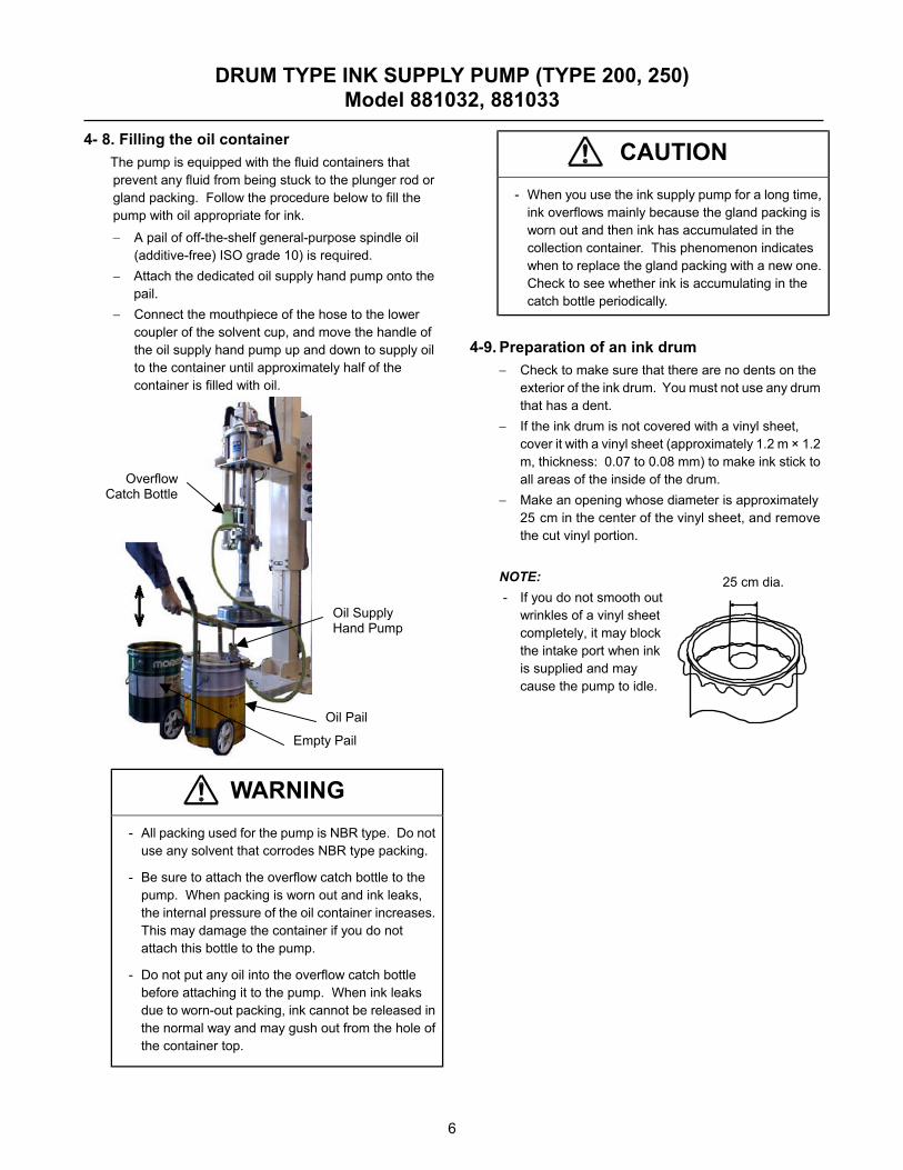
4- 8. Filling the oil container
The pump is equipped with the fluid containers that prevent any fluid from being stuck to the plunger rod or gland packing. Follow the procedure below to fill the pump with oil appropriate for ink. − A pail of off-the-shelf general-purpose spindle oil
(additive-free) ISO grade 10) is required. − Attach the dedicated oil supply hand pump onto the
pail. − Connect the mouthpiece of the hose to the lower
coupler of the solvent cup, and move the handle of the oil supply hand pump up and down to supply oil to the container until approximately half of the container is filled with oil.
WARNING - All packing used for the pump is NBR type. Do not
use any solvent that corrodes NBR type packing.
- Be sure to attach the overflow catch bottle to the pump. When packing is worn out and ink leaks, the internal pressure of the oil container increases. This may damage the container if you do not attach this bottle to the pump.
- Do not put any oil into the overflow catch bottle before attaching it to the pump. When ink leaks due to worn-out packing, ink cannot be released in the normal way and may gush out from the hole of the container top.
CAUTION - When you use the ink supply pump for a long time,
ink overflows mainly because the gland packing is worn out and then ink has accumulated in the collection container. This phenomenon indicates when to replace the gland packing with a new one. Check to see whether ink is accumulating in the catch bottle periodically.
4-9. Preparation of an ink drum
− Check to make sure that there are no dents on the exterior of the ink drum. You must not use any drum that has a dent.
− If the ink drum is not covered with a vinyl sheet, cover it with a vinyl sheet (approximately 1.2 m × 1.2 m, thickness: 0.07 to 0.08 mm) to make ink stick to all areas of the inside of the drum.
− Make an opening whose diameter is approximately 25 cm in the center of the vinyl sheet, and remove the cut vinyl portion.
NOTE: - If you do not smooth out
wrinkles of a vinyl sheet completely, it may block the intake port when ink is supplied and may cause the pump to idle.
Empty Pail
Oil Pail
Oil Supply Hand Pump
Overflow Catch Bottle
7
DRUM TYPE INK SUPPLY PUMP (TYPE 200, 250) Model 881032, 881033
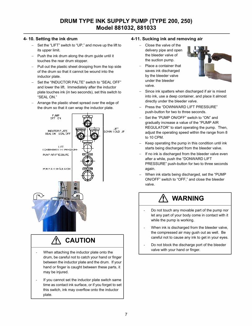
4- 10. Setting the ink drum
− Set the “LIFT” switch to “UP,” and move up the lift to its upper limit.
− Push the ink drum along the drum guide until it touches the rear drum stopper.
− Pull out the plastic sheet drooping from the top side of the drum so that it cannot be wound into the inductor plate.
− Set the “INDUCTOR PALTE” switch to “SEAL OFF” and lower the lift. Immediately after the inductor plate touches ink (in two seconds), set this switch to “SEAL ON.”
− Arrange the plastic sheet spread over the edge of the drum so that it can wrap the inductor plate.
CAUTION - When attaching the inductor plate onto the
drum, be careful not to catch your hand or finger between the inductor plate and the drum. If your hand or finger is caught between these parts, it may be injured.
- If you cannot set the inductor plate switch same time as contact ink surface, or if you forget to set this switch, ink may overflow onto the inductor plate.
4-11. Sucking ink and removing air − Close the valve of the
delivery pipe and open the bleeder valve of the suction pump.
− Place a container that saves ink discharged by the bleeder valve under the bleeder valve.
− Since ink spatters when discharged if air is mixed into ink, use a deep container, and place it almost directly under the bleeder valve.
− Press the “DOWNWARD LIFT PRESSURE” push-button for two to three seconds.
− Set the “PUMP ON/OFF” switch to “ON” and gradually increase a value of the “PUMP AIR REGULATOR” to start operating the pump. Then, adjust the operating speed within the range from 8 to 10 CPM.
− Keep operating the pump in this condition until ink starts being discharged from the bleeder valve.
− If no ink is discharged from the bleeder valve even after a while, push the “DONWARD LIFT PRESSURE” push-button for two to three seconds again.
− When ink starts being discharged, set the “PUMP ON/OFF” switch to “OFF,” and close the bleeder valve.
WARNING - Do not touch any movable part of the pump nor
let any part of your body come in contact with it while the pump is working.
- When ink is discharged from the bleeder valve, the compressed air may gush out as well. Be careful not to cause any ink to get in your eyes.
- Do not block the discharge port of the bleeder valve with your hand or finger.

8
DRUM TYPE INK SUPPLY PUMP (TYPE 200, 250) Model 881032, 881033
4- 12. Adjusting the air pressure that operates
the pump − Set the “PUMP AIR REGULATOR” to the regulated
operation air pressure, and push the knob to lock it. − Check to see how the pump plunger moves up and
down. If the pump plunger moves down clearly faster than it moves up, it means that the suction capability of the pump cannot handle this condition. So, decrease the operation air pressure to adjust the pump so that it can operate normally.
NOTES − If the plunger moves down faster than it moves up,
the pump cannot discharge sufficient ink, and but the life of the pump is shortened if you continue operating the pump under this condition.
− The range of the normal operational air pressure changes depending on the viscosity and temperature of ink.
CAUTION - The maximum available pressure of the pump is
0.7 MPa. If you try to set the higher pressure, the pump may be damaged or it may cause injury or damage the surrounding. Never increase the pressure to 0.7 MPa or higher.
- Operate the pump with the lowest possible pressure (air pressure). This reduces meaningless movements and prevents each part from being worn out.
4-13. Cleaning the inside of the oil container
and replacing solvent The plunger sliding section and oil container of the pump are sealed with packing. When the plunger slides up and down repeatedly, solvent is accumulated at the rim of the plunger. Clean the plunger periodically.
− Connect the hose mouthpiece of the dedicated oil evacuation gun to the lower coupler of the oil container, and suck oil by pulling the handle of the solvent removing device to discard it into the waste oil tank.
− Follow Section 8 “Filling the oil container” to pour new oil from the upper coupler of the oil container into the container until the container is filled half-full with oil.
− When you move the handle of the oil removing device connected to the lower coupler back and forth, oil poured into the container is stirred, and it cleans the inside of the container. When you replace the used oil with new oil and repeatedly stir the container several times, the container is cleaned.
− Finally, pour new oil into the container until approximately half of the container is filled with oil.
CAUTION - To clean the plunger, stop the pump at its upper
movable limit. If you try to clean the plunger while it is moving, your finger may be caught between the plunger and the oil container, and could result in an injury.
4-14. Maintenance and inspection
− As part of your the routine inspection, check to see how much oil has accumulated in the container due to leakage. Replace the oil with new oil according to the amount of the increased liquid.
− Further tighten each connection of the pump: (1) During the regular maintenance operation (2) If air leak or ink leak is detected during routine
inspection. − Since packing and other similar parts of the pump
are worn out depending on how frequently they are used, check them regularly and replace them with new ones when necessary.
Plunger
Oil Container
Oil Evacuation Gun
9
DRUM TYPE INK SUPPLY PUMP (TYPE 200, 250) Model 881032, 881033
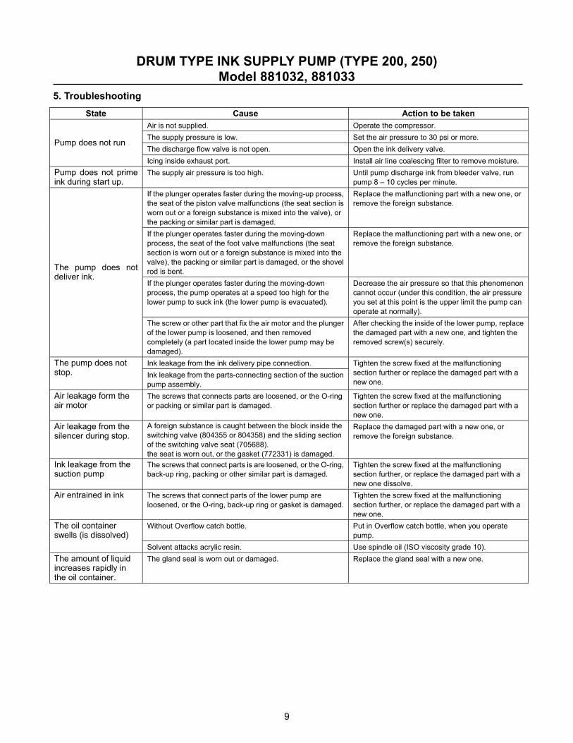
5. Troubleshooting State Cause Action to be taken
Air is not supplied. Operate the compressor. The supply pressure is low. Set the air pressure to 30 psi or more. The discharge flow valve is not open. Open the ink delivery valve.
Pump does not run
Icing inside exhaust port. Install air line coalescing filter to remove moisture. Pump does not prime ink during start up.
The supply air pressure is too high. Until pump discharge ink from bleeder valve, run pump 8 – 10 cycles per minute.
If the plunger operates faster during the moving-up process, the seat of the piston valve malfunctions (the seat section is worn out or a foreign substance is mixed into the valve), or the packing or similar part is damaged.
Replace the malfunctioning part with a new one, or remove the foreign substance.
If the plunger operates faster during the moving-down process, the seat of the foot valve malfunctions (the seat section is worn out or a foreign substance is mixed into the valve), the packing or similar part is damaged, or the shovel rod is bent.
Replace the malfunctioning part with a new one, or remove the foreign substance.
If the plunger operates faster during the moving-down process, the pump operates at a speed too high for the lower pump to suck ink (the lower pump is evacuated).
Decrease the air pressure so that this phenomenon cannot occur (under this condition, the air pressure you set at this point is the upper limit the pump can operate at normally).
The pump does not deliver ink.
The screw or other part that fix the air motor and the plunger of the lower pump is loosened, and then removed completely (a part located inside the lower pump may be damaged).
After checking the inside of the lower pump, replace the damaged part with a new one, and tighten the removed screw(s) securely.
Ink leakage from the ink delivery pipe connection. The pump does not stop. Ink leakage from the parts-connecting section of the suction
pump assembly.
Tighten the screw fixed at the malfunctioning section further or replace the damaged part with a new one.
Air leakage form the air motor
The screws that connects parts are loosened, or the O-ring or packing or similar part is damaged.
Tighten the screw fixed at the malfunctioning section further or replace the damaged part with a new one.
Air leakage from the silencer during stop.
A foreign substance is caught between the block inside the switching valve (804355 or 804358) and the sliding section of the switching valve seat (705688). the seat is worn out, or the gasket (772331) is damaged.
Replace the damaged part with a new one, or remove the foreign substance.
Ink leakage from the suction pump
The screws that connect parts is are loosened, or the O-ring, back-up ring, packing or other similar part is damaged.
Tighten the screw fixed at the malfunctioning section further, or replace the damaged part with a new one dissolve.
Air entrained in ink The screws that connect parts of the lower pump are loosened, or the O-ring, back-up ring or gasket is damaged.
Tighten the screw fixed at the malfunctioning section further, or replace the damaged part with a new one.
Without Overflow catch bottle. Put in Overflow catch bottle, when you operate pump.
The oil container swells (is dissolved)
Solvent attacks acrylic resin. Use spindle oil (ISO viscosity grade 10). The amount of liquid increases rapidly in the oil container.
The gland seal is worn out or damaged. Replace the gland seal with a new one.
10
DRUM TYPE INK SUPPLY PUMP (TYPE 200, 250) Model 881032, 881033
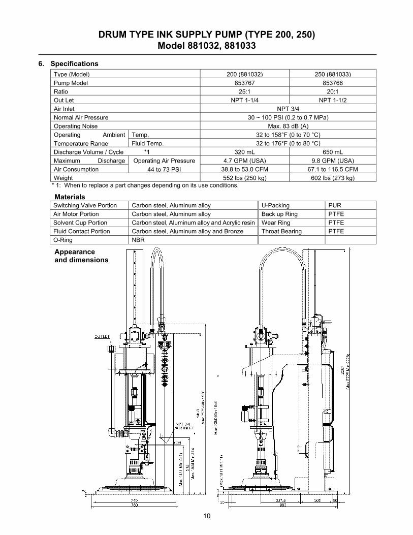
6. Specifications
Type (Model) 200 (881032) 250 (881033) Pump Model 853767 853768 Ratio 25:1 20:1 Out Let NPT 1-1/4 NPT 1-1/2 Air Inlet NPT 3/4 Normal Air Pressure 30 ~ 100 PSI (0.2 to 0.7 MPa) Operating Noise Max. 83 dB (A)
Temp. 32 to 158°F (0 to 70 °C) Operating Ambient Temperature Range Fluid Temp. 32 to 176°F (0 to 80 °C) Discharge Volume / Cycle *1 320 mL 650 mL Maximum Discharge 4.7 GPM (USA) 9.8 GPM (USA) Air Consumption
Operating Air Pressure 44 to 73 PSI 38.8 to 53.0 CFM 67.1 to 116.5 CFM
Weight 552 lbs (250 kg) 602 lbs (273 kg) * 1: When to replace a part changes depending on its use conditions.
Materials Switching Valve Portion Carbon steel, Aluminum alloy U-Packing PUR Air Motor Portion Carbon steel, Aluminum alloy Back up Ring PTFE Solvent Cup Portion Carbon steel, Aluminum alloy and Acrylic resin Wear Ring PTFE Fluid Contact Portion Carbon steel, Aluminum alloy and Bronze Throat Bearing PTFE O-Ring NBR
Appearance and dimensions
11
DRUM TYPE INK SUPPLY PUMP (TYPE 200, 250) Model 881032, 881033
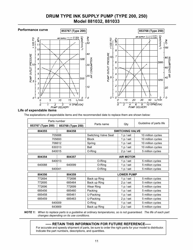
Performance curve Life of expendable items
The explanations of expendable items and the recommended date to replace them are shown below:
Parts number 853767 (Type 200) 853768 (Type 250) Parts name Qty Guideline of parts life
804355 804358 SWITCHING VALVE 705688 Switching Valve Seat 1 p / set 10 million cycles 705693 Block 1 p / set 10 million cycles 706612 Spring 1 p / set 10 million cycles 630313 Ball 1 p / set 10 million cycles 640015 O-Ring 2 p / set 5 million cycles
804354 804357 AIR MOTOR 640013 O-Ring 1 p / set 5 million cycles
640088 640099 O-Ring 1 p / set 5 million cycles 640041 O-Ring 1 p / set 5 million cycles
804356 804359 LOWER PUMP 772694 772698 Back up Ring 1 p / set 5 million cycles 772695 685464 Back up Ring 2 p / set 5 million cycles 772696 772699 Wear Ring 1 p / set 5 million cycles 685456 685460 Packing 1 p / set 5 million cycles 685458 685461 U-Packing 1 p / set 5 million cycles 685459 685463 U-Packing 2 p / set 5 million cycles
640009 O-Ring 1 p / set 5 million cycles 643669 Back up Ring 2 p / set 5 million cycles
NOTE 1: When to replace parts is a guideline at ordinary temperatures, so is not guaranteed. The life of each part changes depending on its use conditions.
----- RETAIN THIS INFORMATION FOR FUTURE REFERENCE----- For accurate and speedy shipment of parts, be sure to order the right parts for your model to distributor. Indicate the part numbers, descriptions, and quantities.
853767 (Type 200) 853768 (Type 250)
12
DRUM TYPE INK SUPPLY PUMP (TYPE 200, 250) Model 881032, 881033
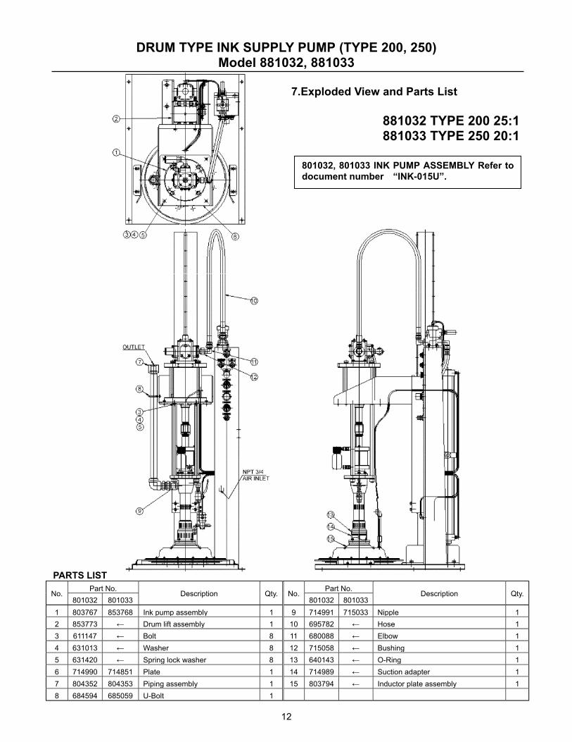
7.Exploded View and Parts List
881032 TYPE 200 25:1 881033 TYPE 250 20:1
PARTS LIST
Part No. Part No. No.
801032 801033 Description Qty. No.
801032 801033 Description Qty.
1 803767 853768 Ink pump assembly 1 9 714991 715033 Nipple 1 2 853773 ← Drum lift assembly 1 10 695782 ← Hose 1 3 611147 ← Bolt 8 11 680088 ← Elbow 1 4 631013 ← Washer 8 12 715058 ← Bushing 1 5 631420 ← Spring lock washer 8 13 640143 ← O-Ring 1 6 714990 714851 Plate 1 14 714989 ← Suction adapter 1 7 804352 804353 Piping assembly 1 15 803794 ← Inductor plate assembly 1 8 684594 685059 U-Bolt 1
801032, 801033 INK PUMP ASSEMBLY Refer todocument number “INK-015U”.
13
DRUM TYPE INK SUPPLY PUMP (TYPE 200, 250) Model 881032, 881033
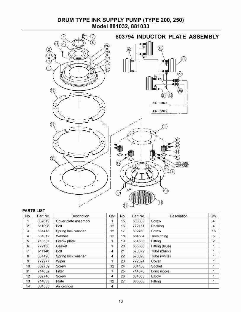
803794 INDUCTOR PLATE ASSEMBLY
PARTS LIST No. Part No. Description Qty. No. Part No. Description Qty. 1 832619 Cover plate assembly 1 15 603033 Screw 4 2 611098 Bolt 12 16 772151 Packing 4 3 631418 Spring lock washer 12 17 602760 Screw 16 4 631012 Washer 12 18 684534 Tees fitting 6 5 713587 Follow plate 1 19 684535 Fitting 2 6 772150 Gasket 1 20 685366 Fitting (blue) 1 7 611148 Bolt 4 21 570072 Tube (black) 1 8 631420 Spring lock washer 4 22 570090 Tube (white) 1 9 772277 Wiper 1 23 772624 Cover 1 10 602759 Screw 12 24 634138 Socket 1 11 714832 Filter 1 25 714870 Long nipple 1 12 602746 Screw 4 26 634003 Elbow 1 13 714833 Plate 12 27 685368 Fitting 1 14 684533 Air cylinder 4
14
DRUM TYPE INK SUPPLY PUMP (TYPE 200, 250) Model 881032, 881033
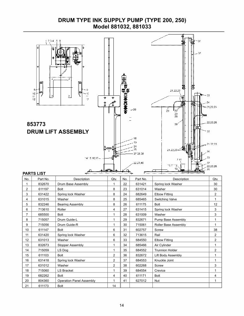
PARTS LIST No. Part No. Description Qty. No. Part No. Description Qty. 1 832670 Drum Base Assembly 1 22 631421 Spring lock Washer 30 2 611197 Bolt 8 23 631014 Washer 30 3 631422 Spring lock Washer 8 24 682649 Elbow Fitting 2 4 631015 Washer 8 25 685465 Switching Valve 1 5 832246 Bearing Assembly 8 26 611175 Bolt 12 6 713610 Roller 4 27 631415 Spring lock Washer 3 7 685500 Bolt 1 28 631009 Washer 3 8 715057 Drum Guide-L 1 29 832671 Pump Base Assembly 1 9 715056 Drum Guide-R 1 30 715061 Roller Base Assembly 1
10 611147 Bolt 6 31 602757 Screw 38 11 631420 Spring lock Washer 6 32 713615 Rail 2 12 631013 Washer 6 33 684550 Elbow Fitting 2 13 832673 Stopper Assembly 1 34 685466 Air Cylinder 1 14 715059 LS Dog 1 35 684552 Trunnion Holder 2 15 611103 Bolt 2 36 832672 Lift Body Assembly 1 16 631418 Spring lock Washer 2 37 684553 Knuckle Joint 1 17 631012 Washer 2 38 602268 Screw 3 18 715060 LS Bracket 1 39 684554 Crevice 1 19 682262 Bolt 4 40 611171 Bolt 4 20 804360 Operation Panel Assembly 1 41 627012 Nut 1 21 611173 Bolt 14
853773 DRUM LIFT ASSEMBLY
15
DRUM TYPE INK SUPPLY PUMP (TYPE 200, 250) Model 881032, 881033
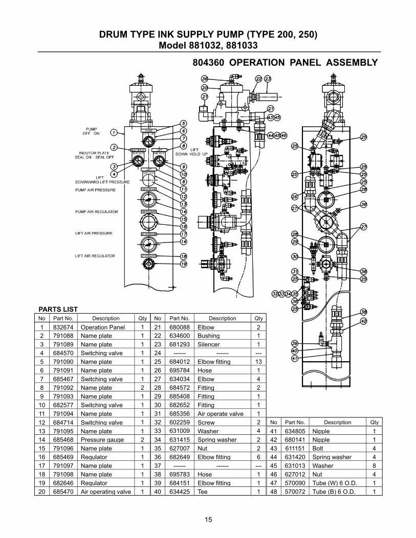
804360 OPERATION PANEL ASSEMBLY
PARTS LIST No Part No. Description Qty No Part No. Description Qty1 832674 Operation Panel 1 21 680088 Elbow 2 2 791088 Name plate 1 22 634600 Bushing 1 3 791089 Name plate 1 23 681293 Silencer 1 4 684570 Switching valve 1 24 ------ ------ --- 5 791090 Name plate 1 25 684012 Elbow fitting 13 6 791091 Name plate 1 26 695784 Hose 1 7 685467 Switching valve 1 27 634034 Elbow 4 8 791092 Name plate 2 28 684572 Fitting 2 9 791093 Name plate 1 29 685408 Fitting 1
10 682577 Switching valve 1 30 682652 Fitting 1 11 791094 Name plate 1 31 685356 Air operate valve 1 12 684714 Switching valve 1 32 602259 Screw 2 No Part No. Description Qty13 791095 Name plate 1 33 631009 Washer 4 41 634805 Nipple 1 14 685468 Pressure gauge 2 34 631415 Spring washer 2 42 680141 Nipple 1 15 791096 Name plate 1 35 627007 Nut 2 43 611151 Bolt 4 16 685469 Regulator 1 36 682649 Elbow fitting 6 44 631420 Spring washer 4 17 791097 Name plate 1 37 ------ ------ --- 45 631013 Washer 8 18 791098 Name plate 1 38 695783 Hose 1 46 627012 Nut 4 19 682646 Regulator 1 39 684151 Elbow fitting 1 47 570090 Tube (W) 6 O.D. 1 20 685470 Air operating valve 1 40 634425 Tee 1 48 570072 Tube (B) 6 O.D. 1
16
DRUM TYPE INK SUPPLY PUMP (TYPE 200, 250) Model 881032, 881033
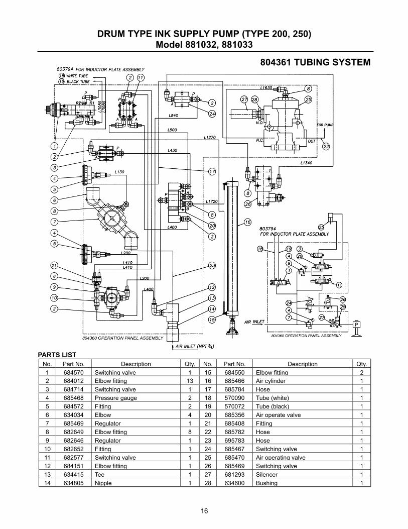
804361 TUBING SYSTEM
PARTS LIST No. Part No. Description Qty. No. Part No. Description Qty. 1 684570 Switching valve 1 15 684550 Elbow fitting 2 2 684012 Elbow fitting 13 16 685466 Air cylinder 1 3 684714 Switching valve 1 17 685784 Hose 1 4 685468 Pressure gauge 2 18 570090 Tube (white) 1 5 684572 Fitting 2 19 570072 Tube (black) 1 6 634034 Elbow 4 20 685356 Air operate valve 1 7 685469 Regulator 1 21 685408 Fitting 1 8 682649 Elbow fitting 8 22 685782 Hose 1 9 682646 Regulator 1 23 695783 Hose 1 10 682652 Fitting 1 24 685467 Switching valve 1 11 682577 Switching valve 1 25 685470 Air operating valve 1 12 684151 Elbow fitting 1 26 685469 Switching valve 1 13 634415 Tee 1 27 681293 Silencer 1 14 634805 Nipple 1 28 634600 Bushing 1