Embed Size (px)
Citation preview
1
HEAT TECH HEAT PUMPINSTALLATION &
OPERATION MANUAL
Heat Tech Heat Pump ModelsALLWH 3.2kW, 5.0kW & 7.2kW
A guide to the Installation and Operation of Heat Tech Heat PumpsPLEASE READ THIS MANUAL BEFORE INSTALLING AND OPERATING
THE HEAT PUMP
Thank you very much for purchasing our product.Before using your unit, please read this manual carefully and keep it for future reference.

2
HE
AT
T
EC
H H
EA
T P
UM
P
2
Introduction ................................................................................................1
• Features ...................................................................................................................1• About heat pumps ....................................................................................................1• Why Heat Tech..........................................................................................................2• Specifications ............................................................................................................3• Dimensions of units ..................................................................................................3• Cautions and warnings ................................................................................................4
Installation Instructions .............................................................................5
• Materials ..................................................................................................................5• Installation Diagram ..................................................................................................6• Location ...................................................................................................................7• Positioning of unit .....................................................................................................8• Plumbing: water connections .....................................................................................9• Electrical controller and thermostat connections ...................................................10-11
Start-up Process ......................................................................................12
Trial Operation ..........................................................................................13
Care, Maintenance & Service ....................................................................14
Wire Controller ....................................................................................15-17
Error Code Explanation ........................................................................18-19
About Operation Range ............................................................................20
Warranty ..............................................................................................21-22
Contact Information..................................................................................23
N.B: This Installation Manual is the property of Heat Tech Heat Pumps, and all rights of copyright are reserved. It may not be reproduced or used for any other purpose without written permission from Heat Tech. In the interests of product improvement, Heat Tech reserves the right to change specifications without prior notice. It is the responsibility of the user to ensure the relevant issue of this Manual is utilised. Heat Tech accepts no responsibility for loss or damage as a result of alleged errors, omissions or subsequent alterations to this Manual.
Content

1
HE
AT
T
EC
H H
EA
T P
UM
P
1
Features of the Heat Tech Domestic Heat Pump Water Heater
As electricity prices rise, so many more people are turning to Heat Pumps as a replacement for energy-inefficient electric element geysers. The advantages of Heat Tech Heat Pumps are:
• Heat Tech Heat Pumps use R410A refrigerant that enables water to be heated to 60ºC.• Control panel allows the consumer to conveniently set water temperature and timing to desired requirements.• High efficiency and energy-saving; thermal efficiency and Co-efficiency of performance as high as 4.0. • Heat Tech Heat pumps cut water heating costs by up to two-thirds.• Electricity savings through the use of a Heat Tech Heat Pump can repay the total investment within 1.5 to 4 years. (dependant on usage)• Capital outlay costs of purchasing and installing a Heat Tech Heat Pump are generally lower than those of other comparable water heating system.• Aesthetically pleasing and no solar panels on roof required• Effective in all weather conditions – whether cloudy or rainy & can heat at night when the electricity demand is low.• Easy operation and automatic control, with automatic start-up, shutdown and automatic defrosting which saves any manual operation.• Can be retro-fitted to an existing hot water cylinder by an Heat Tech-certified installer.• Heat Tech Heat Pumps are backed nationwide and guaranteed by Heat Tech branches in all major metropolitan areas.• For more information, visit our website: www.heattech.co.za
About Heat Pumps• It is important to ensure the size of the unit matches the lifestyle of house i.e how many people in house and how much hot water is used. • The heating process of a heat pump is that it absorbs heat from the ambient temperature and transfers it to water. Should the ambient temperature decrease so will the heating capacity and thus also the rate of heating the water. • Upsizing the unit e.g. from a 3.2kw to a 5kw is often a good solution:
• There will be less strain on the machine • Will ensure a quicker turnaround of water• Increased efficiencies of the machine
Guide TableThis is to be used as a guide only and sizing of units must take end users lifestyle and application into consideration:
Model Recommended Number of People Size of existing geyser
Turnaround time of heating water*
ALLWH3.2kW 2 100-150 2 hoursALLWH5.0kW 2 / 3 150 – 250 1hr 45ALLWH7.2kW 4 + 300- 500 2 hours
* Dependant on ambient conditions
Introduction

2
HE
AT
T
EC
H H
EA
T P
UM
P
2
Why Heat Tech
C
M
Y
CM
MY
CY
CMY
K
HT HEAT PUMP A4 FLYER FAP.pdf 1 2015/04/08 5:40 PM
3
HE
AT
T
EC
H H
EA
T P
UM
P
3
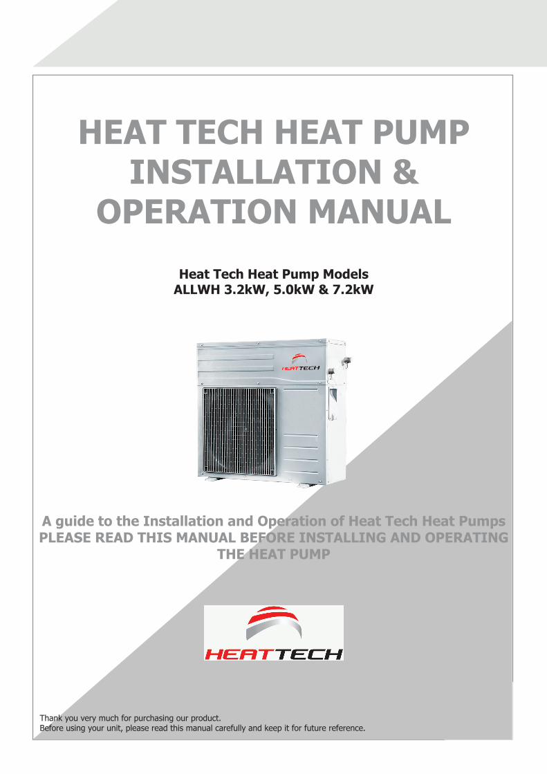
Model 32 (B) 50 (B) 72 (B)
Heating Capacity
Condition 1 3500W 5000W 7200W
Conditon 2 3200W 4400W 6500W
Condition 3 3650W 5100W 7400W
Standard power
Condition 1 1010W 1290W 2020W
Conditon 2 850W 1080W 1600W
Condition 3 1040W 1340W 2080W
Max power 1550W 1950W 2750W
Power supply 220V-240V~ 50Hz
Operation control Manual start, auto start, failure alarm etc.
Safety device High pressure protection, hydraulic protectionoverload protection, temperature protection, etc
Working substance (Charged volume) R410A(950g)
R410A(1200g)
R410A(1300g)
Water Circulate param.
Water outlet temp Default factory setting temperature 50°C
Liquid side heat exchanger Double pipe heat exchanger
Max. resisting pressure 0.7mpa
Note:Conditions 1: Outdoor ambient temperature is DB/WB 20°C/15°C, inlet water temperature of the units is 15°C, outlet water 55°C Conditions 2: Outdoor ambient temperature is DB/WB 7°C/6°C, inlet water temperature of the units is 30°C, outlet water 35°C Conditions 3: Outdoor ambient temperature is DB/WB 15°C/12°C, inlet water temperature of the units is 40°C, outlet water 45°C Actual heating output would be changed according to the change of outdoor temperature and relative humidity.
Dimensions of unit
MODEL A B C DALLWH3.2 KW 563 295 100 790ALLWH5.0 KW 563 295 100 790ALLWH7.2 KW 560 335 140 845
Specifications
B
Throu gh ho le (12 22 li nea r hole )×
A
CD

4
HE
AT
T
EC
H H
EA
T P
UM
P
4
Cautions and Warnings
Should you detect any abnormality such as a smell of fire, turn off the unit in order to avoid damage or injury, and call your supplier for instructions.!
DANGER!
All electrical connections to this Heat Tech Heat pump must be done by suitably qualified personnel, and in compliance with all applicable local and national rules and regulations. An improper electrical connection will create a hazard that could result in injury or death or damage to property. The electrical mains switch is to be switched off before working on or near the unit. As there are no user-serviceable components within the unit, only qualified Heat Tech-trained technicians should open the unit and service it; end-users must not open the unit.
!CAUTION!
Hot water can be dangerousIn keeping with international safety standards, Heat Tech have restricted maximum water temperature of the unit to 60ºC. Temperatures above this level increase the hazard of scalding. If there are infants or elderly people in the home, it is recommended that a lower outlet water temperature be selected.
!CAUTION!
Avoid water damage. Stop valve on the water inlet to be closed before undertaking work on the unit. Ensure that the geyser drip tray is in good condition to avoid damage to property.!
CAUTION!
Transport of the Heat Tech Heat Pump unit. Heat pump must always be transported in original packaging and kept upright during storage and transport as indicated on the packaging. The unit should not be leaned more than 45degrees. If unit is transported on its side or upside down, permanent damage may be caused. When removing packaging, avoid damage to evaporator fins which are easily bent, and lower gently into position.
!CAUTION!
Do not insert fingers or any object into the air inlet or outlet, as injury or damage could be caused by rotating fan. Do not allow children to play with the unit. Also do not use any flammable sprays (e.g. hair spray) near the unit to avoid possibility of fire.!
CAUTION!
Heat Pump can start at any time without prior warning.
Delay re-startDo not switch unit off and immediately on again, but wait 30 seconds for refrigerant pressure to equalise.
!CAUTION!
The water quality standard applicable for the unit
Ph value Total hardness Conductivity Sulphur ion Chlorine ion Ammonia ion6.5-8.0 <200μV/
cm(25°C)<50 ppm No <50 ppm No
Sulphate ion Silicon Iron content Sodium ion Calcium ion<50 ppm <30 ppm <0.3 ppm No requirement <50 ppm
See www.dwaf.gov.za for further information.
In areas where the water has a high lime content, it may be necessary to install a water softener or electronic de-scaler. An indication of this would be an excessive lime deposit such as on the element of a kettle. Heat Tech does not warrant against failure due to lime scale build-up in the heat exchanger.
High Lime
Content

5
HE
AT
T
EC
H H
EA
T P
UM
P
5
Installation of Heat Tech Heat Pumps may only be carried out by qualified and authorised, Heat Tech-trained installers who possess the necessary plumbing, electrical and or airconditioning certifications. Before installation, confirm model and serial number to avoid mistaken installation.The installer must be familiar with the relevant:
• SANS 10254: ‘The installation, maintenance, replacement and repair of fixed electric storage, water heating systems’,
• SANS 10252, Part 1: ‘Water supply installations for buildings’, and also all local by-laws.
• SANS 1352: The installation, maintenance, replacement and repair of domestic air source water heating heat pump systems
Many installed geysers do not conform to specifications and the end-user needs to be informed – in writing- before installation begins. When in any doubt please refer to these specification standards.
Installation Instructions
Accessories
Accessory name Qty. Shape PurposeInstallation & Owner's
Manual1 This
ManualFor installation and use
Y-shaped Filter 1 ---- To filter inlet waterWire controller assembly 1 ---- Control units and Display units
statusSeal Ring 1 ---- Discharge condensate water
Water outllet jointing pipe 1 ---- Discharge condensate waterWater tank sensor 1 ---- Detect water tank temperature
5-core shielded cable (10m)
1 ---- Connect outdoor unit and wire controller

6
HE
AT
T
EC
H H
EA
T P
UM
P
6
Installation Instructions
A - Vacuum BreakerB - Dual TP ValveC - Solar Drain Cock D - Lever Ball Valve (within 1m of HP)E - Y Strainer - ¾ Copper Piping - Armor Flex, UV protection if pipes are outside
CIRCUIT BREAKERS:
PANEL
HOT WATER SUPPLY TO
HOUSE
ELECTRICAL CABLE(2.5mm twin & earth norse)
COLD WATER SUPPLY
(PRV - valve)
CHANGEOVER SWITCH
SAFETY VALVE DISCHARGE
HEAT PUMP(not further than 8m and not lower than 3m from geyser)
DISTRIBUTION BOARD
A
B
C
D D
E
300m
m
ISOLATOR SWITCH (outside, in weather
proof box,1m from heat pump)
IN
OUT
Model Manual Switch (A) Fuse(A)
ALLWH3.2Kw 20 15
ALLWH5.0Kw 20 15
ALLWH7.2Kw 30 25
Items to be removed Replaced with New Installation
Cobra StrainerCobra Dual Draincock Cobra 3/4” Ball Valve
A
300m
m
7
HE
AT
T
EC
H H
EA
T P
UM
P
7
Installation Instructions
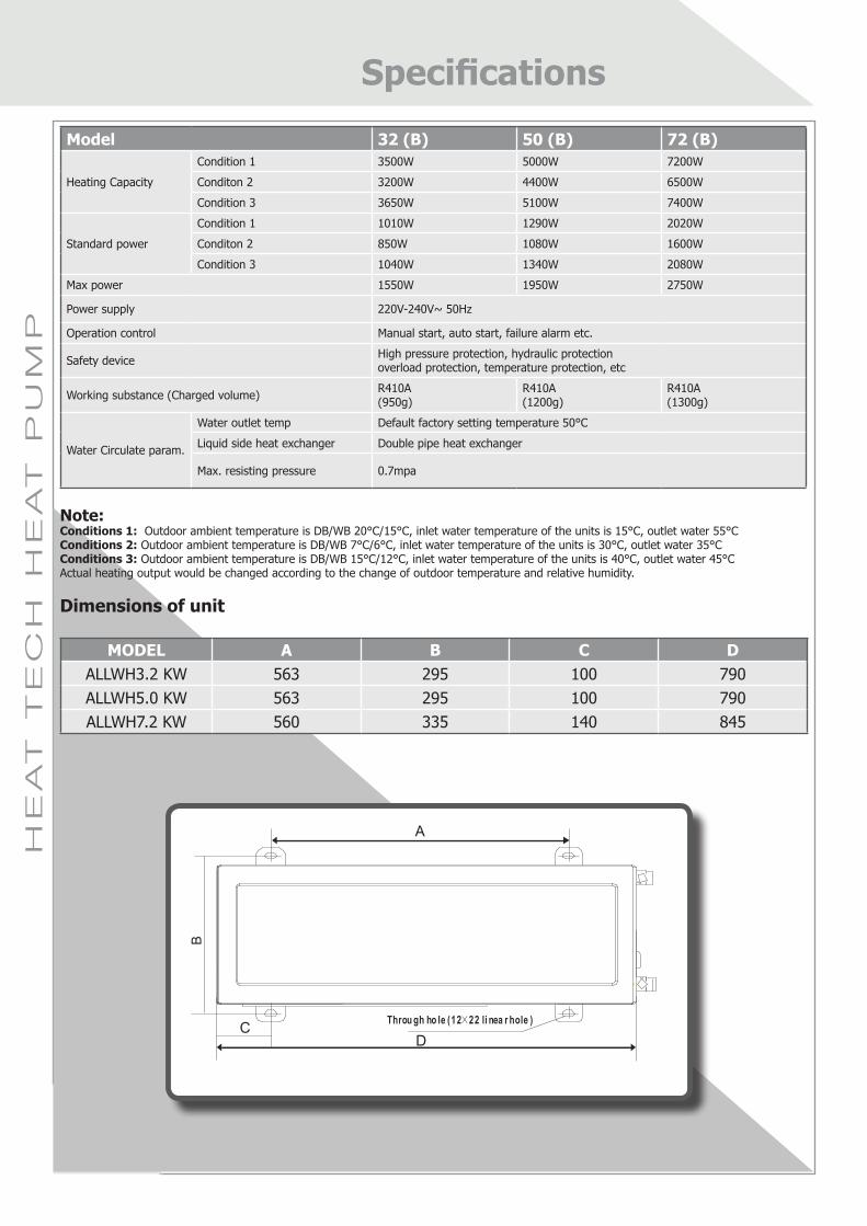
Unit Specifications
Model ALLWH3.2kW ALLWH5.0kW ALLWH7.2kWPower Supply Ph-V-Hz 1-220-50 1-220-50 1-220-50Water Heating Heating Output kW 3.65 5.1 7.4
Heating Input kW 1 1.32 1.96COP 3.7 4.2 4.4Rated Current A 3.7 6 8.5
Recommended Water Tank
Volume L 100 ~ 250 100 ~ 400 100 ~ 500
Refrigerant R410A R410A R410AOutdoor Noise Level dB(A) 49 55 55Max. Pipe Length m 8 8 8Max. Height Difference m 3 3 3Operating Conditions (Ambient Temp) 0C -7 0C~43 0C -7 0C~43 0C -7 0C~43 0CWater Outlet Temp. 0C 40~60 40~60 40~60
300m
m
200mm Main unit
Air outlet
Prohibit any blocking to the air outlet
1500
mm
600mm
>
> >
>
200mm>
Main unit 600mm>
200m
m>
500m
m>
300m
m
200mm Main unit
Air outlet
Prohibit any blocking to the air outlet
1500
mm
600mm
>
> >
>
200mm>
Main unit 600mm>
200m
m>
500m
m>
Location of unitBefore installing the unit ensure there that the air flow to the Heat Tech Heat Pump unit is not restricted. Allow enough space for the installation and maintenance. See diagram below
Fix with bolts

8
HE
AT
T
EC
H H
EA
T P
UM
P
8
Materials required for installationTo be supplied by installer:1. Plumbing connections - these can be obtained from plumbing retailers 2. Suitable outdoor electrical cable. Check rating plate for electrical specifications.3. Waterproof electrical isolator to be located close to the Heat Pump that will interrupt all electrical power to the unit.4. UV-resistant thermal insulation to insulate all water pipes.
POSITIONING OF UNIT
• The Heat Pump must be within 8 metres of geyser/storage tank, with a maximum of 3 metres difference in height. The heat pump should not be installed higher than the storage vessel
• Damage due to water on the unit or flooding is not covered by the Warranty. Unit not to be mounted where it is subject to excessive run-off from a roof or lawn sprinklers etc.
• The Heat Tech Heat Pump unit is designed for outdoor location, and should not be placed in an enclosed area such as a roof or garage, unless mechanical ventilation is provided to ensure adequate air circulation. The unit is not suited for a ducted application. If cold air is discharged and recirculated into the unit, its efficiency will be greatly reduced. Circulating air volume not to be less than 2400m³/hour.
• Although the Heat Tech Heat Pump is extremely quiet in operation, avoid placing it on walls or in areas where there is a risk of transmitting vibration or sound into rooms such as bedrooms.
• Do not place Heat Pump in locations where damage could be caused by water or condensate leakage. If necessary provide a drain pipe to divert condensate from the unit.Condensate will increase as humidity increases.
• Ensure drain holes in the base of the unit are clear of any debris that could cause blockage and subsequently cause corrosion.
N.B. As cold air is discharged from the unit in operation, avoid placing near animal enclosures, dog kennels, bird cages etc.
Wall mountingMount the Heat Tech Heat Pump using supplied brackets against a flat surface above ground level ensuring it is not subject to flood damage Brackets kits are available from Heat Tech. Inspect the quality of the brick work prior to any drilling and mounting. Always use a spirit level to ensure the unit is installed straight.
Bracket Length 3.2 kW 550mm5 kW 550mm
7.2 kW 650mm
!CAUTION!
Installation Instructions
• Installing the unit in a location where the power supply fluctuates (e.g. factories) may cause problems• Avoid placing unit in any area where flammable gas is leaked

9
HE
AT
T
EC
H H
EA
T P
UM
P
9
PLUMBING CONNECTIONS
All plumbing work is to be undertaken by an authorised and Heat Tech-approved contractor.
• Water inlet and outlet connections are clearly marked. It is very important that piping to the storage tank is correctly connected.• We recommend that all pipes be lagged before they are installed as this will ease the installation process.• A mandatory lever shut-off valve must be positioned on both pipe connections. These are required for servicing• The Y-shaped strainer supplied with the Heat Tech unit must be positioned on the inlet water pipe as near to the unit as possible. If this is not installed, the warranty becomes null and void.
Maximum/minimum water pressuresThe minimum water inlet pressure required is 0.2Mpa. The maximum water inlet pressure is 0.7Mpa. Should pressure exceed this, a pressure relief valve is to be fitted, and needs to be checked on a regular basis to remove lime deposits and ensure it is not blocked.• Water may drip from the discharge pipe of the pressure relief device, so this pipe must be left open to the atmosphere in a frost-free environment.
Piping connections to hot water cylinder
ReturnConnect the hot water outlet of the heat pump to the additional connection point situated in the middle on the side of the geyser
FlowRemove geysers drain cock and replace with a dual port drain cock. Connect the cold water inlet of the heat pump to the dual port drain cock on the geyser. Alternatively tee into the geysers cold water supply pipe between the geysers cold water shut off valve and the drain cock. Connection must be within 500mm of the drain cock.
Plumbing Connections
No. Name Connective pipe specification
a Circulating water outlet of main unit DN20b Circulating water inlet of main unit DN20c Circulating water outlet of water tank DN20d Circulating water inlet of water tank DN20e Cold water inlet DN20f Heatwater outlet DN20g Safety valve DN20
10
HE
AT
T
EC
H H
EA
T P
UM
P
10
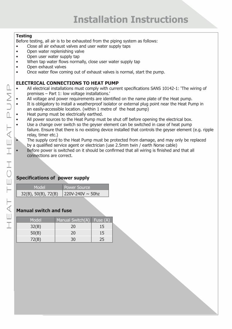
TestingBefore testing, all air is to be exhausted from the piping system as follows:• Close all air exhaust valves and user water supply taps• Open water replenishing valve• Open user water supply tap• When tap water flows normally, close user water supply tap• Open exhaust valves• Once water flow coming out of exhaust valves is normal, start the pump.
ELECTRICAL CONNECTIONS TO HEAT PUMP• All electrical installations must comply with current specifications SANS 10142-1: ‘The wiring of premises – Part 1: low voltage installations.’• All voltage and power requirements are identified on the name plate of the Heat pump.• It is obligatory to install a weatherproof isolator or external plug point near the Heat Pump in an easily-accessible location. (within 1 metre of the heat pump)• Heat pump must be electrically earthed.• All power sources to the Heat Pump must be shut off before opening the electrical box.• Use a change over switch so the geyser element can be switched in case of heat pump failure. Ensure that there is no existing device installed that controls the geyser element (e.g. ripple relay, timer etc.)• The supply cord to the Heat Pump must be protected from damage, and may only be replaced by a qualified service agent or electrician (use 2.5mm twin / earth Norse cable)• Before power is switched on it should be confirmed that all wiring is finished and that all connections are correct.
Installation Instructions
Specifications of power supply
Model Power Source32(B), 50(B), 72(B) 220V-240V ~ 50hz
Manual switch and fuse
Model Manual Switch(A) Fuse (A)32(B) 20 1550(B) 20 1572(B) 30 25

11
HE
AT
T
EC
H H
EA
T P
UM
P
11
Wire Controller
TEM
P SE
NSO
RIN
WAT
ER T
ANK
Please connect by 5-bit shielded wire in accessory bag
PLEASE CONNECTWITH THE ATTACHEDT5 TEMp SENSOR
GND
RedXP10
XS10
T5
Black
N
L
Power Cable
Power Supply
Min. wire size (mm²)(Metal pipe & synthetic
resin pipe wire)
Manual Switch (A)
RCCB ModelSize(Continuous
length ≤30m)
Ground Wire
Capacity Fuse
32(B)50(B)
220V-240V ~ 50Hz
1.5 1.5 20 1530 mA Below 0.1 sec
LBC-16-1-CP
72(B)2.5 2.5 30 25
Electric Wiring Diagram
Model
Item
Installation Instructions
12
HE
AT
T
EC
H H
EA
T P
UM
P
12
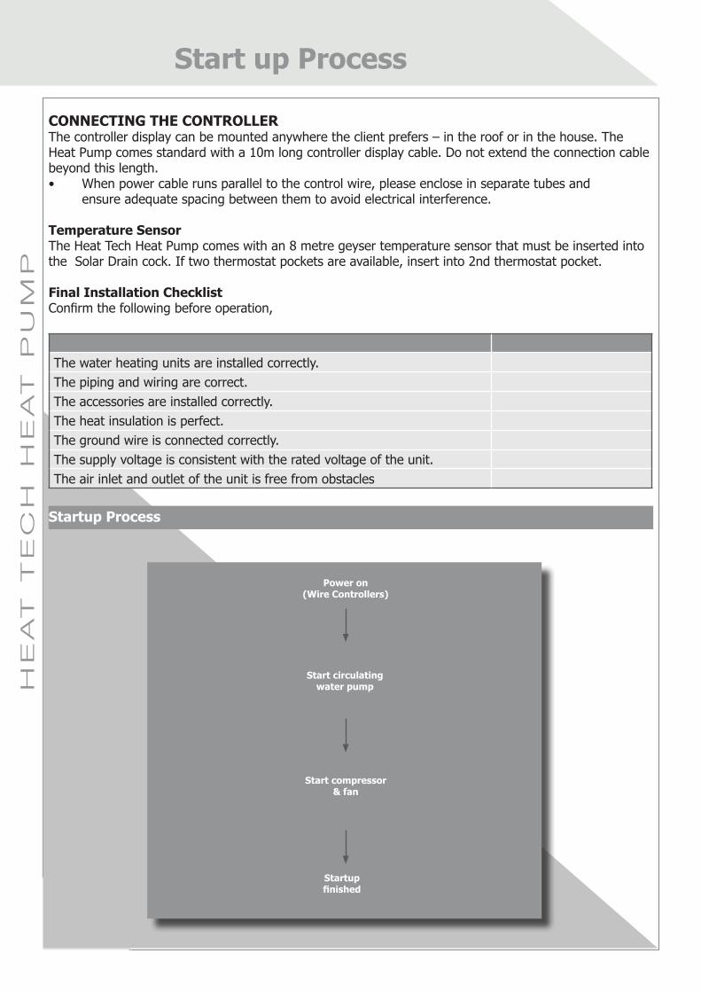
CONNECTING THE CONTROLLERThe controller display can be mounted anywhere the client prefers – in the roof or in the house. The Heat Pump comes standard with a 10m long controller display cable. Do not extend the connection cable beyond this length.• When power cable runs parallel to the control wire, please enclose in separate tubes and ensure adequate spacing between them to avoid electrical interference.
Temperature SensorThe Heat Tech Heat Pump comes with an 8 metre geyser temperature sensor that must be inserted into the Solar Drain cock. If two thermostat pockets are available, insert into 2nd thermostat pocket.
Final Installation ChecklistConfirm the following before operation,
The water heating units are installed correctly.The piping and wiring are correct.The accessories are installed correctly.The heat insulation is perfect.The ground wire is connected correctly.The supply voltage is consistent with the rated voltage of the unit.The air inlet and outlet of the unit is free from obstacles
Startup Process
Start up Process
Power on (Wire Controllers)
Start circulating water pump
Start compressor & fan
Startup finished
2 min later
60s later

13
HE
AT
T
EC
H H
EA
T P
UM
P
13
Trial Operation Check
Control the heat pump operation by using a wired controller and check the following items in accordance with the User’s Manual (If any error, please eliminate it according to the error code explanation and analysis in the end of this manual.): Check that • The wired controller switch is in working order.• The functional buttons of the wired controller are correct.• The indicator light lights up correctly.• The manual operation button operates.• The drainage is correct.• The unit operates normally in the heating mode. • The outlet water temperature is correct.• The vibration is okay or if there any abnormal sounds when operating.• There is no refrigerant leaking
Operational ExplanationsAbout the Three-minute ProtectionIf you re-run the unit or turn on the manual switch after the unit stops, the unit will not start within three minutes because of the self-protection function of the compressor.Auto Adjustment of Fan MotorIf the ambient temperature is high when the unit is operating, the fan motor of the unit might be on the low-wind operation.
Defrosting in the Air Supply OperationWhen frost occurs during the heat supply, the defrosting function will operate automatically to improve the heating effect (about 2-10 minutes).The fan motor will stop running when defrosting.
Winter Start UpIn areas where the temperature drops below 0ºC, it is essential to keep unit in operation to avoid damage through freezing. If however the heat pump is not used in this period, drain the unit to prevent the formation of ice in the condenser as this can cause damage and result in the need to replace major components. The warranty does not cover damage to the condenser and piping due to freezing.
Operating ConditionsFor the proper use of heat pump, please operate at the outdoor temperature -7 °C ~ 43°C. As there are precision electronic components inside the unit, it is strictly prohibited to use untreated water such as from a lake, river or borehole water.
Power off• All operations will stop when the power is off.• The operation indicator of the wired controller will flash slowly for several seconds to notify re-start after power off. (check)• If any malfunction occurs due to lightning surge or other electrical interference, switch off manual power switch, re-start and press On/Off button again.
Start up Process

14
HE
AT
T
EC
H H
EA
T P
UM
P
14
CARE AND MAINTENANCE
As there are no user-serviceable parts within the Heat Pump, owner maintenance simply involves ensuring that there is an unobstructed airflow through the evaporator, and that the drain holes underneath are clear. Keep foliage trimmed back away from the unit and ensure that any leaves, clippings, plastic bags etc do not restrict airflow. After the unit has been operating for a long period, and dependent on quality of water supply, dirt may accumulate in the tank which then needs to be periodically cleaned by draining the storage vessel
SERVICE
It is a specified condition of the Heat Tech Warranty that the Heat Pump is serviced by an authorised Heat Tech Service Contractor annually.
Step 1 - Electrical TerminalsThese are to be checked annually for good connection to ensure they do not become loose and result in unit malfunction or possible fire hazard.
Step 2 - Water System & Y StrainerThe water circulation pump must be checked to ensure it is operating normally. The Y water strainer is to be cleaned and heat exchanger coils checked for fouling. Dirty or fouled heat exchangers result in inefficient operation, and if fouled, a chemical cleaning treatment may be necessary.
Step 3 - Unit PerformanceDuring servicing, readings must be taken of temperature, pressure and electrical characteristics, and the overall performance of the unit assessed. Generally, a fault code will be displayed on the controller which will assist in diagnosis of the problem.
Step 4 - CleaningBecause a dirty evaporator will result in decreased efficiency, the evaporator should be cleaned whenever visibly dirty, preferably twice a year. The outer surface of the unit may be cleaned with a sponge and warm soapy water. Do not use bleach, abrasive cleaners or solvents which will damage the paintwork.
N.B. If the Heat pump is going to be shut down for an extended period, the drain valve should be left open.
Care/Maintenance and Service
!CAUTION!
!WARNING!
When the evaporator is being cleaned with a low-pressure hose, ensure that the power to the unit is switched off.
Water that is draining from the Heat Pump could be hot and result in injury by scalding.Do not allow anyone to come into contact with this water.

15
HE
AT
T
EC
H H
EA
T P
UM
P
15
WIRE CONTROLLER
Contents: 1. Set up 2. Settings a. Setting the clock b. Setting the on/off timers c. Setting desired water temperature d. Setting temperature differential 3. System Check 4. Other buttonsSet up
Feature: This controller can be used for various models of Heat Tech Heat Pumps, thus it iscritical that the controller is set to the correct heat pump model • Setting 1 - (default) is for commercial heat pumps (10,20, 38kw) • Setting 3 - for commercial swimming pool heat pumps (45, 90kw) • Setting 5 - Domestic heat pumps (3.2, 5, 7.2kW)
How do I change this? 1. Ensure the controller is powered off 2. Hold the left and right arrows buttons down simultaneously for 3 sec 3. Number will start flashing 4. Press the up/down button till the desired setting number (see above) is seen 5. Press ok
Hint: If a conflict button appears - it means that the controller has not been set correctly for the installed machine
Wire Controller
Operation icon
Mode area
Setting temperature
Timing on/off
Constrain Key
Left Right Key
Cancel key
Function Icon
On-line Unit Qty. Indication
Water Level indication
Clock
Water temp.
ON/OFF Key
Confirm Key
Left Right Key
Set KeyAdd and Reduce key

16
HE
AT
T
EC
H H
EA
T P
UM
P
16
Settings
A. Set the Clock/Time
1. Press the "SET" key 3 times to enter clock settings. The hour will flash. 2. Press the" "or" "keys to adjust and press the" "key when finished. 3. Now the minutes will flash. Press the" "or" "keys to adjust then press the "OK" key, or wait for 7 seconds, to confirm. 4. During the setting process, press the "CANCEL" key anytime to exit without saving.
B. Setting the Timer
Feature: The controller allows for 3 timing settings to be programmed
How do I do this?
1. Press "SET" key twice to enter timing 2. Now the "hour" will flash for Time period 1 3. Press the"▲" or "▼"keys to adjust the hour then press the "►" key when finished. Set the "minute" in the same way 4. Press the "►" key when finished. 5. Now set the time off in the same manner 6. Press the "►" key when finished 7. Set timers 2 & 3 in the same manner if desired 8. Press ok when completed
Check timing information: to check which time periods have been set, press the"◄ " or "►" keys under the main page. The "ON" and "OFF" times for Time period 1, Time period2 and Time period 3 will be displayed in sequence.
Cancel timing: press and hold the "CANCEL" key for 3 seconds. All the effective Time periods will be cancelled.
C. Setting tank temperature
Feature: Set what temperature of water you require in the geyserTip: Most normal geyser thermostats are set to 60°C. However 55°C is more that adequate. In winter you may want to adjust the temperature higher as users tend to shower longer and in hotter water. However please note that the heat pump is least efficient when raising the water temperature from 55 to 60°C.
How do I set the differential?
1. Press the "▲" or "▼" keys to adjust the water temperature after the controller is powered ON. 2. Alternatively, press the "SET" key once when "SET WATER TEMP" is displayed on the LCD and then press "▲" or "▼" to adjust the water temperature.
Wire Controller
17
HE
AT
T
EC
H H
EA
T P
UM
P
17
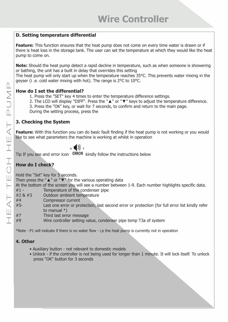
D. Setting temperature differential
Feature: This function ensures that the heat pump does not come on every time water is drawn or if there is heat loss in the storage tank. The user can set the temperature at which they would like the heat pump to come on.
Note: Should the heat pump detect a rapid decline in temperature, such as when someone is showering or bathing, the unit has a built in delay that overrides this settingThe heat pump will only start up when the temperature reaches 35°C. This prevents water mixing in the geyser (i .e. cold water mixing with hot). The range is 2°C to 10°C.
How do I set the differential? 1. Press the "SET" key 4 times to enter the temperature difference settings. 2. The LCD will display "DIFF". Press the "▲" or "▼" keys to adjust the temperature difference. 3. Press the "OK" key, or wait for 7 seconds, to confirm and return to the main page. During the setting process, press the
3. Checking the System
Feature: With this function you can do basic fault finding if the heat pump is not working or you would like to see what parameters the machine is working at whilst in operation
Tip If you see and error icon kindly follow the instructions below
How do I check?
Hold the "Set" key for 5 seconds.Then press the "▲" or "▼" for the various operating dataAt the bottom of the screen you will see a number between 1-9. Each number highlights specific data.#1 - Temperature of the condenser pipe#2 & #3 Outdoor ambient temperature#4 Compressor current#5- Last one error or protection, last second error or protection (for full error list kindly refer to manual *)#7 Third last error message#9 Wire controller setting value, condenser pipe temp T3a of system
*Note - P1 will indicate if there is no water flow - i,e the heat pump is currently not in operation 4. Other • Auxiliary button - not relevant to domestic models • Unlock - if the controller is not being used for longer than 1 minute. It will lock itself. To unlock press "OK" button for 3 seconds
Wire Controller

18
HE
AT
T
EC
H H
EA
T P
UM
P
18
ERROR CODE EXPLANATION AND ANALYSIS
Code Code Explanation Cause Analysis SolutionE1 Power phase order error
E2 Communication failure
Communication failure between the main unit and the wired controller
Connect the main unit with the A, B, P, Q and E lines of the wired controller correctly.
Electromagnetic interference because communication line is not the shielded line
Replace the communication line with the shielded line.
Damage of the sensor Replace the sensor
E3 Outlet Water Temperature Sensor Error
E4 Water temp. sensor failure in the water tank
The T5 port between the sensor and the motherboard is loose Insert the port well.
Sensor damage Replace the sensor.
E5 Condenser Temp. Sensor failure
The T3 port between the sensor and the motherboard is loose Insert the port well.
Sensor damage Replace the sensor.
E6 Outdoor ambient temp. Sensor failure
The T4 port between the sensor and the motherboard is loose Insert the port well.
Sensor damage Replace the sensor.
E7 Sensor failure at water pump outlet
The T6 port between the sensor and the motherboard is loose Insert the port well.
Sensor damage Replace the sensor.
E9 T8 Temperature Sensor Error
Error Code Explanation and Analysis

19
HE
AT
T
EC
H H
EA
T P
UM
P
19
EdSensor failure at the double-pipe refrigerant outlet
The T2 port between the sensor and the motherboard is loose Insert the port well.
Sensor damage Replace the sensor.
Leakage of refrigerantCheck the leaking place, mend by welding, exhaust the air and add refrigerant again.
P1 System high pressure protection
The circulating pipe between the water tank and the main unit is too small Use the DN 20 pipe
The circulating pipe between the water tank and the main unit is too long
The length of the connecting pipe should be ≤ 5 m
The height difference between the water tank and the main unit is too large
The height difference should be ≤ 3 m
There is air in the water pump Exhaust the air (see Chapter Three)
The water pump is not started Check whether the water pump is damaged
The capillary is blocked off (small possibility)
Weld the capillary and add refrigerant. Blow it clear by high pressure air or replace it.
No water in the water tank and the tap water supply is stopped
Shut down the unit and start until the tap water supply recovers to be normal
P2 System current protection
The circulating pipe between the water tank and the main unit is too small Use the DN 20 pipe
The height difference between the water tank and the main unit is too large
The height difference should be ≤ 3 m
There is air in the water pump Exhaust the air
The water pump is not started Check whether the water pump is damaged
The capillary is blocked off (small possibility)
Weld the capillary and add refrigerant. Blow it clear by high pressure air or replace it.
P3 N/A
P4 Tt High pressure protection
P5 Condenser high pressure protection
P8
Protection for the over-high temperature at the outlet of the condenser (T2 ≥ 60 ℃)
Water pump is not startedCut off the power supply, remove the bolt on the back of the water pump and turn the water pump axis
There is air in the water pump Exhaust the air
The water pump is not started Check whether the water pump is damaged
P9 Anti-freezing protection
Pb Anti-freezing protection Prevent PTE cracking by freezing in the winter
Normal protection, no need for treatment.
HO Indoor and outdoor units unmatched
Error Code Explanation and Analysis

20
HE
AT
T
EC
H H
EA
T P
UM
P
20
About Operation Range
-0.5
0.5
1.5
2.5
3.5
4.5
5.5
0 500 1000 1500 2000 2500 3000 3500 4000 4500 5000
-15 -10 - 5 0 5 10 1 5 20 2 5 30 3 5 40 45
CO
P(W
/W)
Cap
acity
(W)
Ambient temperature (℃) ① Capacity ②COP
①
②
32(B)Unit capacity and energy efficiency diagram
NOTE:
• Conditions1: Inlet water temperature of the units is 150C, outlet water temperature 550C
• Conditions2: Inlet water tempereature of the units is 300C, outlet water temperature 350C
60
55
-15 -7 43
Wat
er O
utle
t Te
mpe
ratu
re (
C0)
Outdoor Temperature (C0)MODEL: 32(B), 50(B), 72(B)
50576570
Wat
er O
utle
t Te
mpe
ratu
re (
C0)
Outdoor Temperature (C0)
MODEL: 32(B)
-7
45
-2 2 7 10 43
-0.5
0.5
1.5
2.5
3.5
4.5
5.5
0
1000
2000
3000
4000
5000
6000
7000
-15 -10 - 5 0 5 10 15 20 2 5 30 3 5 40 45
CO
P(W
/W)
Cap
acity
(W)
Ambient temperature (℃) ① Capacity ② COP
①
②
50(B)Unit capacity and energy efficiency diagram
-0.5
0.5
1.5
2.5
3.5
4.5
5.5
0
1000
2000
3000
4000
5000
6000
7000
8000
9000
-15 -10 -5 0 5 1 0 15 2 0 25 3 0 35 4 0 45
CO
P(W
/W)
Cap
acity
(W)
Ambient temperature( ℃) ①Capacity ② COP
①
②
72(B)Unit capacity and energy efficiency diagram

21
HE
AT
T
EC
H H
EA
T P
UM
P
21
HEAT PUMP LIMITED WARRANTY FORM
Model No: __________________________ Invoice Date ____________________
Serial No: _________________________________________________________
Customer Name: ___________________________________________________
Installation Address: ________________________________________________
Company Name of Installer: __________________________________________
The innovation and quality of Heat Tech products is assured by an extensive Research & Development programme. In South Africa, Heat Tech Water heaters are warranted by Heat Tech who warrant to the original owner of the Heat Pump that under conditions of normal use and maintenance, the product is free from defects and workmanship. The warranty is limited in duration as follows:
FULL ONE YEAR WARRANTY: During the first 12 months after purchase, Heat Tech will, through its Authorised Installers, and free of charge to the Owner, repair or replace any parts defective in material or workmanship. Replacement parts may be new or remanufactured, at the sole discretion of Heat Tech. In addition, there is a 2-year warranty on the Wilo circulation pump. (Note however that warranties are null and void should the unit leave South Africa unless prior approval is obtained from Heat Tech.)
LIMITED EXTENDED THREE YEAR COMPRESSOR WARRANTY: During the second and third year after date of invoice, the Compressor carries a parts-only limited warranty (excluding costs of labour, travel and refrigerant).
WARRANTY TERMThe Warranty Term commences on the date of the customer’s invoice and shall run for the full period specified. Thereafter, the warranty period is to be reduced pro-rata by the number of months by which the invoice date is in excess of 1 year from the unit’s date of manufacture. The warranty is limited to the original owner and is not transferable.
EXCLUSIONSThe above-mentioned Limited Warranty does not cover products damaged as a result of accident, abuse, misuse, improper installation or maintenance, or failure of piping or internal components due to freezing, rust, corrosion or scale build-up. The Warranty is rendered also null and void should units leave South Africa unless prior approval is obtained from Heat Tech. Damage caused by failure to operate the heat pump in accordance with Heat Tech's written instructions as well as damage caused by lightning, electrical surges, blown fuses, open circuit breakers, winds, corrosive environments or other.
Heat Tech Warranty

22
HE
AT
T
EC
H H
EA
T P
UM
P
22
CONDITIONS OF WARRANTY
• Should a fault occur on a new Heat Pump following installation and initial satisfactory operation, the Heat Pump will be repaired, not replaced with a new unit.• For HEAT TECH's Limited Warranty to take effect, payment must have been received in full by HEAT TECH and a faxed copy of this Warranty received by HEAT TECH for registration purposes.• HEAT TECH Heat Pumps must be installed by a technician that has received installation and maintenance training directly from HEAT TECH or their Authorised Training Agents. Any unauthorized installation, alteration or repair will void this Warranty. All repairs are to be carried out by a qualified refrigeration technician who is registered in the Safe Handling of Refrigerants. (Further information in this regard may be obtained from HEAT TECH.)• The installer must ensure that the installation fully complies with HEAT TECH’S recommendations concerning installation, water piping and electrical work including electrical earthing of the unit.• All plumbing installations must comply with the current specifications SANS 10254: ‘The installation, maintenance, replacement and repair of fixed electric storage, water heating systems’, as well as the relevant sections of SANS 10252, Part 1: ‘Water supply installations for buildings’, and also all local by-laws.• All electrical installations must comply with current specifications SANS 10142-1: ‘The wiring of premises – Part 1: low voltage installations.’• The installer must ensure that the installation fully complies with the requirements of SANS Code of Practice for Refrigerating Systems.• The size and model of the HEAT TECH Heat Pump selected must be appropriate to the specific application and hot water requirements of the User.• It is a specific condition of this Limited Warranty that the equipment receives one major service annually in accordance with the manufacturer’s recommendation by a service company authorized by HEAT TECH. Half-yearly minor services are also recommended. All non-warranty service charges are the responsibility of the original owner. Any unauthorized alteration or repairs will void this limited warranty. Refrigerant is excluded from this limited warranty. This warranty is not transferable.• Any change in ownership of equipment or change in the appointment of a maintenance contractor must be approved and accepted in writing by HEAT TECH.
Conditions of Warranty

23
HE
AT
T
EC
H H
EA
T P
UM
P
23
Heat Tech Head Office Physical Address: 294 Barolong Street, Icon Park, Sunderland Ridge Ext 1, Centurion, South Africa
Postal Address: P.O. Box 8446, Centurion 0046
Tel: 087 943 7471Fax: 087 941 7403Email: [email protected]
Monday to Friday 07h30 – 16h30Closed Saturdays, Sundays and Public Holidays
Heat Tech After-Sales Service CentreTel: 087 943 7470Email: [email protected]
Monday to Friday: 7h30 – 18h00Saturday, Sunday and Public Holidays: 07h30 – 15h30
Contact Information