Embed Size (px)
Citation preview
Operating instructionsCombined BioFresh-freezer
050614 7085674 - 01BNes/SBNes ... 6
Contents1 Appliance at a glance............................................ 21.1 Description of appliance and equipment.................. 21.2 Range of appliance use............................................ 21.3 Conformity................................................................ 31.4 External dimensions of the appliance....................... 31.5 Saving energy.......................................................... 31.6 HomeDialog............................................................. 32 General safety information................................... 33 Controls and displays........................................... 43.1 Operating and control elements............................... 43.2 Temperature display................................................. 54 Putting into operation............................................ 54.1 Transporting the appliance....................................... 54.2 Installing the appliance............................................. 54.3 Changing over the door hinges................................ 64.4 Water connection..................................................... 84.5 Insertion into a row of kitchen units........................... 94.6 Disposing of packaging............................................ 94.7 Connecting the appliance......................................... 94.8 Switching on the appliance....................................... 95 Control.................................................................... 105.1 Brightness of the temperature display...................... 105.2 Child proofing........................................................... 105.3 Door alarm................................................................ 105.4 Temperature alarm................................................... 105.5 BioFresh compartment............................................. 105.6 Freezer compartment............................................... 126 Maintenance........................................................... 146.1 Defrosting with NoFrost............................................ 146.2 Cleaning the appliance............................................. 146.3 Cleaning the IceMaker............................................. 146.4 Customer service..................................................... 157 Malfunction............................................................. 158 Decommissioning.................................................. 168.1 Switching off the appliance....................................... 168.2 Taking the appliance out of service.......................... 169 Disposing of the appliance................................... 16
The manufacturer works constantly on the further developmentof all the types and models. Therefore please understand thatwe have to reserve the right to make design, equipment andtechnical modifications.To get to know all the benefits of your new appliance, pleaseread the information contained in these instructions carefully.The instructions apply to several models. Differences mayoccur. Text relating only to specific appliances is marked withan asterisk (*).Instructions for action are marked with a , the results ofaction are marked with a .
1 Appliance at a glance1.1 Description of appliance and equip-mentNoteu Shelves, drawers and baskets are arranged for optimum
energy efficiency on delivery.
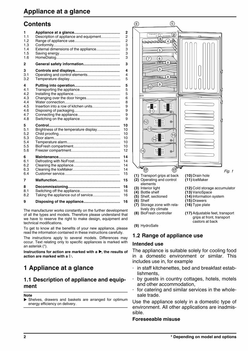
Fig. 1 (1) Transport grips at back (10) Drain hole(2) Operating and control
elements(11) IceMaker
(3) Interior light (12) Cold storage accumulator(4) Bottle shelf (13) VarioSpace(5) Shelf, sectioned (14) Information system(6) Shelf (15) Drawers(7) Storage zone with rela-
tively dry climate(16) Type plate
(8) BioFresh controller (17) Adjustable feet, transportgrips at front, transportcastors at back
(9) HydroSafe
1.2 Range of appliance useIntended useThe appliance is suitable solely for cooling foodin a domestic environment or similar. Thisincludes use in, for example- in staff kitchenettes, bed and breakfast estab-
lishments,- by guests in country cottages, hotels, motels
and other accommodation,- for catering and similar services in the whole-
sale trade.Use the appliance solely in a domestic type ofenvironment. All other applications are inadmis-sible.Foreseeable misuse
Appliance at a glance
2 * Depending on model and options
The following applications are expresslyprohibited:- Storage and cooling of medicines, blood
plasma, laboratory compounds or similarmaterials and products subject to the MedicalDevices Directive 2007/47/EC
- Use in potentially explosive areasImproper use of the appliance can lead todamage to or spoilage of the stored goods.Climate rating definitionsThe appliance is set to operate within specificambient temperature limits according to itsclimate rating. The correct climate rating foryour appliance is indicated on the type plate.NoteuCompliance with the ambient temperatures
indicated is required, otherwise the coolingperformance is reduced.
Climaterating
for ambient temperatures of
SN 10 °C to 32 °CN 16 °C to 32 °CST 16 °C to 38 °CT 16 °C to 43 °C
1.3 ConformityThe refrigerant circuit is tested for leakage. The appliancecomplies with the relevant safety regulations and EC Directives2006/95/EC, 2004/108/EC, 2009/125/EC and 2010/30/EU.The BioFresh compartment satisfies the requirements of a chillcompartment to EN ISO 15502.Note for test institutions:
Tests are to be carried out according to the applicablestandards and guidelines.Preparation and testing of the appliances must be carriedout taking the manufacturer's loading plans and thenotes in the operating manual into account.
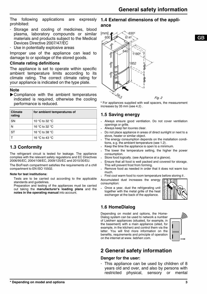
1.4 External dimensions of the appli-ance
Fig. 2 x For appliances supplied with wall spacers, the measurementincreases by 35 mm (see 4.2) .
1.5 Saving energy- Always ensure good ventilation. Do not cover ventilation
openings or grille.- Always keep fan louvres clear.- Do not place appliance in areas of direct sunlight or next to a
stove, heater or similar object.- The energy consumption depends on the installation condi-
tions, e.g. the ambient temperature (see 1.2) .- Keep the time the appliance is open to a minimum.- The lower the temperature setting, the higher the power
consumption.- Store food logically. (see Appliance at a glance).- Ensure that all food is well packed and covered for storage.
This will prevent frost from forming.- Remove food as needed in order that it does not warm too
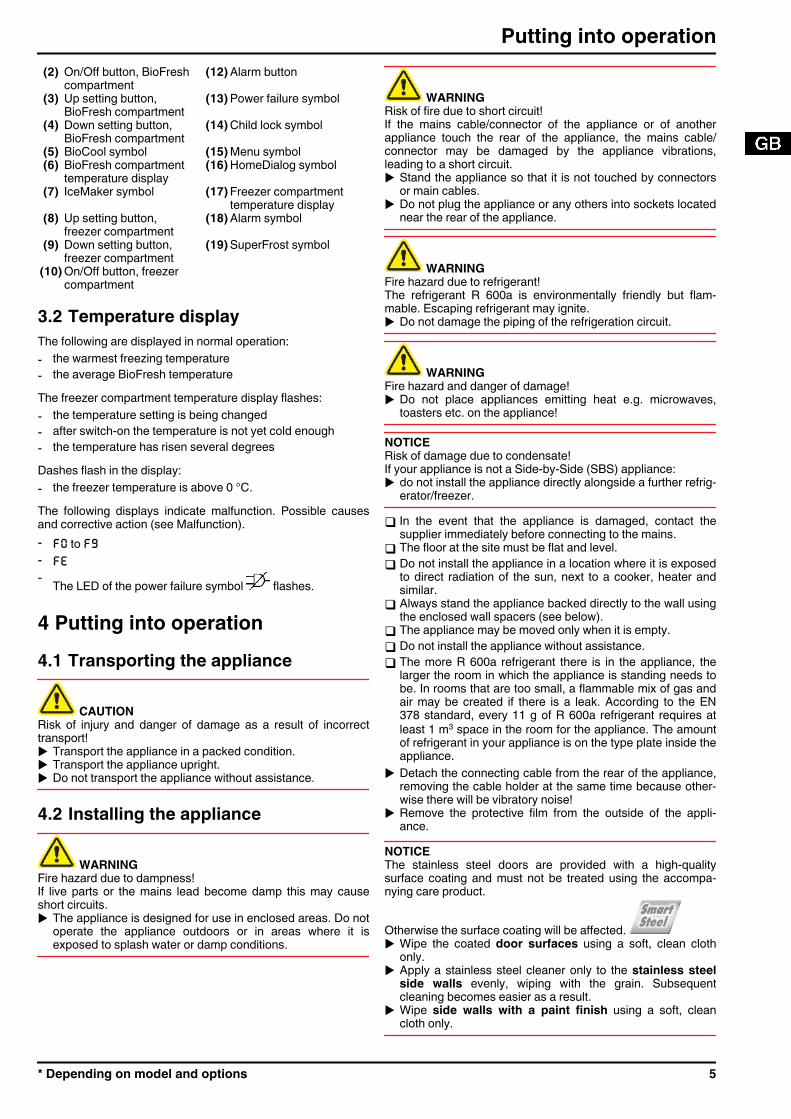
much.- First cool warm food to room temperature before storing it .Accumulated dust increases the energyconsumption:- Once a year, dust the refrigerating unit
together with the metal grille of the heatexchanger at the back of the appliance.
1.6 HomeDialogDepending on model and options, the Home-Dialog system can be used to network a numberof Liebherr appliances (situated, for example, inthe basement) with a main appliance (sited, forexample, in the kitchen) and control them via thelatter. You will find more information on thebenefits, requirements and principle of operationon the internet at www. liebherr.com.
2 General safety informationDanger for the user:- This appliance can be used by children of 8
years old and over, and also by persons withrestricted physical, sensory or mental
General safety information
* Depending on model and options 3
capacity or lack of experience and knowl-edge, if they are supervised or have beeninstructed on safe use of the appliance andunderstand the resulting risks. Children mustnot be allowed to play with the appliance.Cleaning and user maintenance must not becarried out by children without supervision.
- When disconnecting the appliance from thesupply, always take hold of the plug. Do notpull the cable.
- In the event of a fault pull out the mains plugor deactivate the fuse.
- Do not damage the mains power cable. Donot operate the appliance with a defectivemains power cable.
- Have any repairs to or intervention in theappliance, and any change of the mainspower cable, carried out by the customerservice only or by other specialised personneltrained for the purpose.
- Only assemble, connect and dispose of theappliance according to the instructions.
- Please keep these instructions in a safe placeand pass them on to any subsequent owners.
- All repairs to and intervention in the IceMakermay be carried out only by service personnelor by other skilled personnel trained for thepurpose.
- The manufacturer is not liable for damagecaused by a faulty fixed water connection.
- Special-purpose lamps (incandescent lamps,LEDs, fluorescent tubes) in the applianceserve to illuminate the appliance interior andare not suited for room illumination.
Fire hazard:- The refrigerant R 600a is environmentally
friendly but flammable. Escaping refrigerantmay ignite.• Do not damage the refrigerant circuit pipes.• Do not allow naked flames or ignition
sources to enter the appliance.• Do not use any electrical appliances in the
interior (e.g. steam cleaners, heaters, icecream maker etc.).
• If refrigerant escapes: remove any nakedflames or sources of ignition from theleakage area. Ventilate the room well.Notify the after-sales service.
- Do not store explosives or sprays usingcombustible propellants such as butane,propane, pentane, etc. in the appliance. Toidentify these spray cans, look for the list ofcontents printed on the can, or a flamesymbol. Gases possibly escaping may ignitedue to electrical components.
- Keep burning candles, lamps and other itemswith naked flames away from the applianceso that they do not set the appliance on fire.
- Please be sure to store alcoholic drinks orother packaging containing alcohol in tightlyclosed containers. Any alcohol that leaks outmay be ignited by electrical components.
Danger of tipping and falling:- Do not misuse the plinth, drawers, doors etc.
as a step or for support. This applies particu-larly to children.
Danger of food poisoning:- Do not consume food which has been stored
too long.Danger of frostbite, numbness and pain:- Avoid lasting skin contact with cold surfaces
or refrigerated/frozen food or take protectivesteps, e.g. wear gloves. Do not consume icecream, water ice or ice cubes immediatelyand do not consume them too cold.
Danger of injury and damage:- Hot steam can lead to injury. Do not use elec-
trical heating or steam cleaning equipment,open flames or defrosting sprays to defrost.
- Do not use sharp implements to remove theice.
Please observe the specific information inthe other sections:
DANGER identifies a situation involving directdanger which, if not obviated, mayresult in death or severe bodilyinjury.
WARNING identifies a dangerous situationwhich, if not obviated, may result indeath or severe bodily injury.
CAUTION identifies a dangerous situationwhich, if not obviated, may result inminor or medium bodily injury.
NOTICE identifies a dangerous situationwhich, if not obviated, may result indamage to property.
Note identifies useful information and tips.
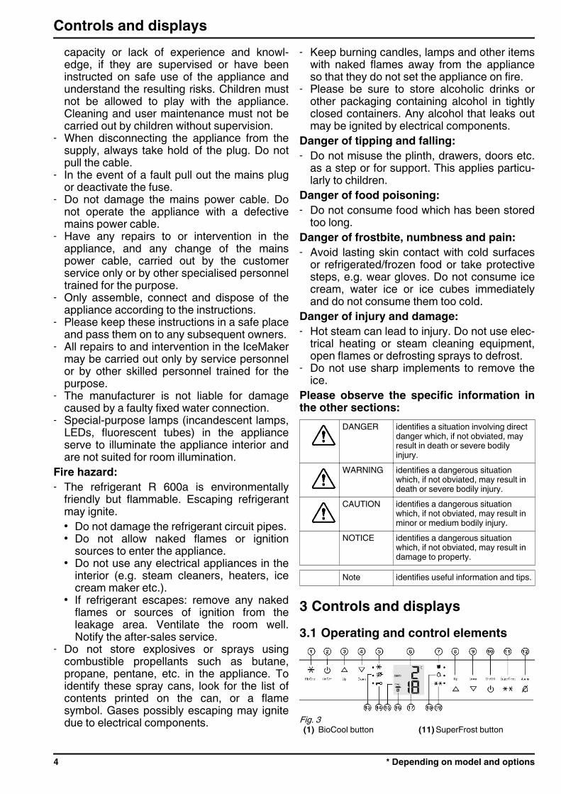
3 Controls and displays3.1 Operating and control elements
Fig. 3 (1) BioCool button (11) SuperFrost button
Controls and displays
4 * Depending on model and options
(2) On/Off button, BioFreshcompartment
(12) Alarm button
(3) Up setting button,BioFresh compartment
(13) Power failure symbol
(4) Down setting button,BioFresh compartment
(14) Child lock symbol
(5) BioCool symbol (15) Menu symbol(6) BioFresh compartment
temperature display(16) HomeDialog symbol
(7) IceMaker symbol (17) Freezer compartmenttemperature display
(8) Up setting button,freezer compartment
(18) Alarm symbol
(9) Down setting button,freezer compartment
(19) SuperFrost symbol
(10) On/Off button, freezercompartment
3.2 Temperature displayThe following are displayed in normal operation:- the warmest freezing temperature- the average BioFresh temperatureThe freezer compartment temperature display flashes:- the temperature setting is being changed- after switch-on the temperature is not yet cold enough- the temperature has risen several degreesDashes flash in the display:- the freezer temperature is above 0 °C.The following displays indicate malfunction. Possible causesand corrective action (see Malfunction).- F0 to F9- FE- The LED of the power failure symbol flashes.
4 Putting into operation4.1 Transporting the appliance
CAUTIONRisk of injury and danger of damage as a result of incorrecttransport!u Transport the appliance in a packed condition.u Transport the appliance upright.u Do not transport the appliance without assistance.
4.2 Installing the appliance
WARNINGFire hazard due to dampness!If live parts or the mains lead become damp this may causeshort circuits.u The appliance is designed for use in enclosed areas. Do not
operate the appliance outdoors or in areas where it isexposed to splash water or damp conditions.
WARNINGRisk of fire due to short circuit!If the mains cable/connector of the appliance or of anotherappliance touch the rear of the appliance, the mains cable/connector may be damaged by the appliance vibrations,leading to a short circuit.u Stand the appliance so that it is not touched by connectors
or main cables.u Do not plug the appliance or any others into sockets located
near the rear of the appliance.
WARNINGFire hazard due to refrigerant!The refrigerant R 600a is environmentally friendly but flam-mable. Escaping refrigerant may ignite.u Do not damage the piping of the refrigeration circuit.
WARNINGFire hazard and danger of damage!u Do not place appliances emitting heat e.g. microwaves,
toasters etc. on the appliance!
NOTICERisk of damage due to condensate!If your appliance is not a Side-by-Side (SBS) appliance:u do not install the appliance directly alongside a further refrig-
erator/freezer.
q In the event that the appliance is damaged, contact thesupplier immediately before connecting to the mains.
q The floor at the site must be flat and level.q Do not install the appliance in a location where it is exposed
to direct radiation of the sun, next to a cooker, heater andsimilar.
q Always stand the appliance backed directly to the wall usingthe enclosed wall spacers (see below).
q The appliance may be moved only when it is empty.q Do not install the appliance without assistance.q The more R 600a refrigerant there is in the appliance, the
larger the room in which the appliance is standing needs tobe. In rooms that are too small, a flammable mix of gas andair may be created if there is a leak. According to the EN378 standard, every 11 g of R 600a refrigerant requires atleast 1 m3 space in the room for the appliance. The amountof refrigerant in your appliance is on the type plate inside theappliance.
u Detach the connecting cable from the rear of the appliance,removing the cable holder at the same time because other-wise there will be vibratory noise!
u Remove the protective film from the outside of the appli-ance.
NOTICEThe stainless steel doors are provided with a high-qualitysurface coating and must not be treated using the accompa-nying care product.
Otherwise the surface coating will be affected. u Wipe the coated door surfaces using a soft, clean cloth
only.u Apply a stainless steel cleaner only to the stainless steel
side walls evenly, wiping with the grain. Subsequentcleaning becomes easier as a result.
u Wipe side walls with a paint finish using a soft, cleancloth only.
Putting into operation
* Depending on model and options 5
u Remove all transit supports.The spacers supplied with some appliances must be used toachieve the stated energy consumption. These will extend thedepth of the appliance by approx. 35 mm. The appliance is fullyfunctional if the spacers are not used, but does have a slightlyhigher energy consumption.u In the case of an appliance with
enclosed wall spacers, mount thewall spacers on the back of theappliance at the top left and right.
u Dispose of packaging material (see 4.6) .u Align the appliance so that it
stands firmly and on a level byapplying the accompanyingspanner to the adjustable-height feet (A) and using aspirit level.
u Then support the door: Extendthe adjustable foot at the turnhinge (B) until it rests on thefloor and then make a further90° turn.
When a Side-by-Side appliance (S…) is fitted together witha second appliance (as a SBS combination):
u Proceed according to the Side-by-Side combined fridge-freezer installation instructions. (Accessories bag of the SBSfreezer/appliance with freezer compartment)
Noteu Clean the appliance (see 6.2) .If the appliance is installed in a very damp environment,condensate may form on the outside of the appliance.u Always see to good ventilation at the installation site.
4.3 Changing over the door hingesYou can change over the door hinges if necessary.NOTICERisk of damage to side-by-side appliances due to condensa-tion!When a side-by-side appliance (S…) is fitted together with asecond appliance (as a SBS combination), the door hingesmust remain as delivered.u Do not change over the door hinges.Ensure that the following tools are to hand:q Torx® 25q Torx® 15q Screwdriverq Cordless screwdriver, if necessaryq Second person for fitting work, if neededq Accompanying Allen key size 2*
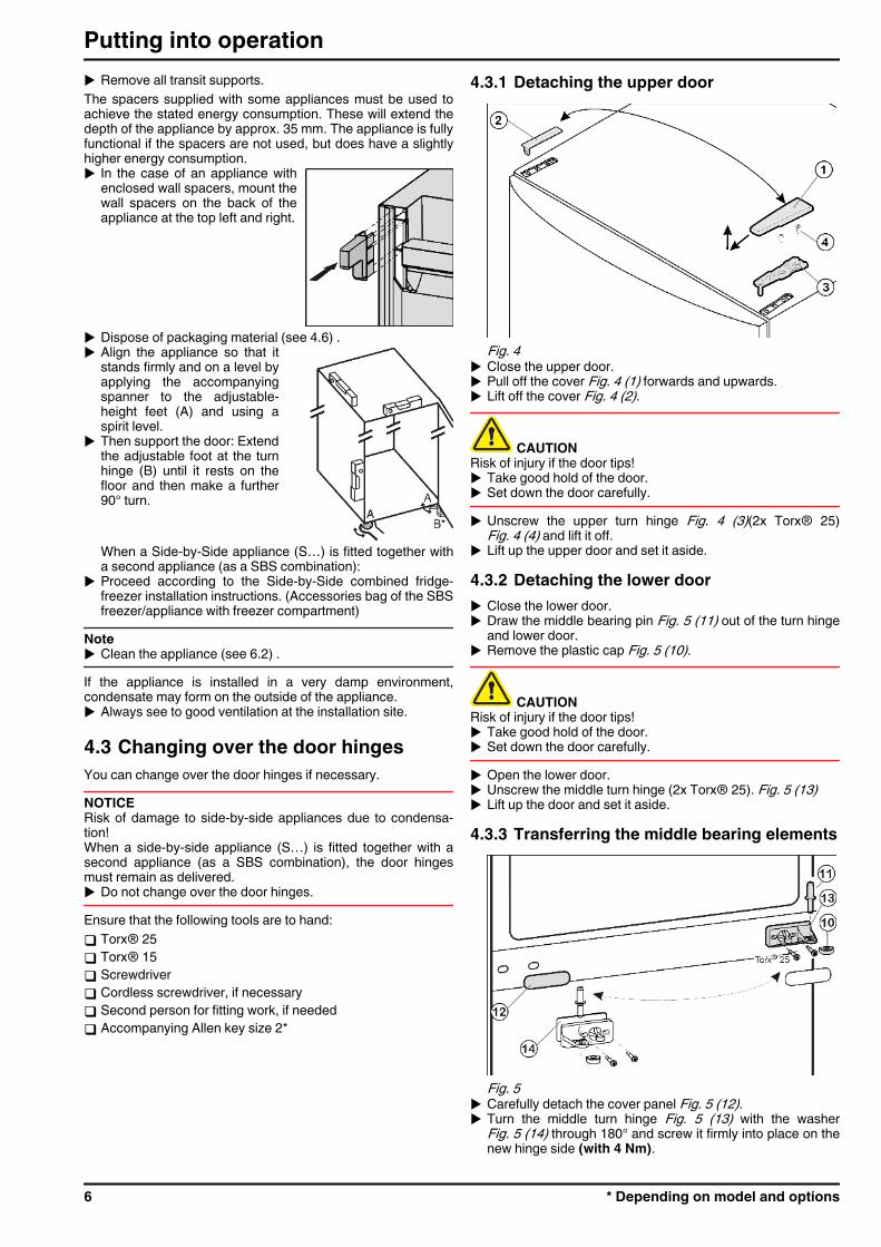
4.3.1 Detaching the upper door
Fig. 4 u Close the upper door.u Pull off the cover Fig. 4 (1) forwards and upwards.u Lift off the cover Fig. 4 (2).
CAUTIONRisk of injury if the door tips!u Take good hold of the door.u Set down the door carefully.u Unscrew the upper turn hinge Fig. 4 (3)(2x Torx® 25)
Fig. 4 (4) and lift it off.u Lift up the upper door and set it aside.
4.3.2 Detaching the lower dooru Close the lower door.u Draw the middle bearing pin Fig. 5 (11) out of the turn hinge
and lower door.u Remove the plastic cap Fig. 5 (10).
CAUTIONRisk of injury if the door tips!u Take good hold of the door.u Set down the door carefully.u Open the lower door.u Unscrew the middle turn hinge (2x Torx® 25). Fig. 5 (13)u Lift up the door and set it aside.
4.3.3 Transferring the middle bearing elements
Fig. 5 u Carefully detach the cover panel Fig. 5 (12).u Turn the middle turn hinge Fig. 5 (13) with the washer
Fig. 5 (14) through 180° and screw it firmly into place on thenew hinge side (with 4 Nm).
Putting into operation
6 * Depending on model and options
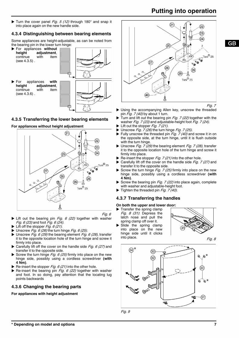
u Turn the cover panel Fig. 5 (12) through 180° and snap itinto place again on the new handle side.
4.3.4 Distinguishing between bearing elementsSome appliances are height-adjustable, as can be noted fromthe bearing pin in the lower turn hinge:u For appliances without
height adjustment,continue with item(see 4.3.5) .
u For appliances withheight adjustment,continue with item(see 4.3.6) .
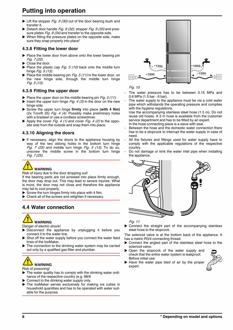
4.3.5 Transferring the lower bearing elementsFor appliances without height adjustment
Fig. 6 u Lift out the bearing pin Fig. 6 (22) together with washer
Fig. 6 (23) and foot Fig. 6 (24).u Lift off the stopper Fig. 6 (21).u Unscrew Fig. 6 (26) the turn hinge Fig. 6 (25).u Unscrew Fig. 6 (29) the bearing element Fig. 6 (28), transfer
it to the opposite location hole of the turn hinge and screw itfirmly into place.
u Carefully lift off the cover on the handle side Fig. 6 (27) andtransfer it to the opposite side.
u Screw the turn hinge Fig. 6 (25) firmly into place on the newhinge side, possibly using a cordless screwdriver (with4 Nm).
u Re-insert the stopper Fig. 6 (21) into the other hole.u Re-insert the bearing pin Fig. 6 (22) together with washer
and foot. In so doing, pay attention that the locating lugpoints backwards
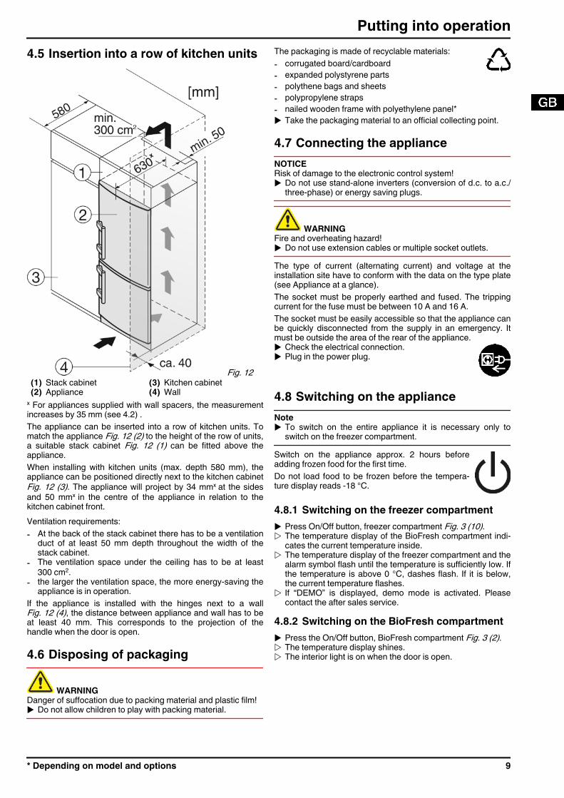
4.3.6 Changing the bearing partsFor appliances with height adjustment
Fig. 7 u Using the accompanying Allen key, unscrew the threaded
pin Fig. 7 (40) by about 1 turn.u Turn and lift out the bearing pin Fig. 7 (22) together with the
washer Fig. 7 (23) and adjustable-height foot Fig. 7 (24).u Lift out the stopper Fig. 7 (21).u Unscrew Fig. 7 (26) the turn hinge Fig. 7 (25).u Fully unscrew the threaded pin Fig. 7 (40) and screw it in on
the opposite side, at the turn hinge, until it is flush outsidewith the turn hinge.
u Unscrew Fig. 7 (29) the bearing element Fig. 7 (28), transferit to the opposite location hole of the turn hinge and screw itfirmly into place.
u Re-insert the stopper Fig. 7 (21) into the other hole.u Carefully lift off the cover on the handle side Fig. 7 (27) and
transfer it to the opposite side.u Screw the turn hinge Fig. 7 (25) firmly into place on the new
hinge side, possibly using a cordless screwdriver (with4 Nm).
u Screw the bearing pin Fig. 7 (22) into place again, completewith washer and adjustable-height foot.
u Tighten the threaded pin Fig. 7 (40).4.3.7 Transferring the handlesOn both the upper and lower door:u Transfer the spring clamp
Fig. 8 (31): Depress thelatch nose and pull thespring clamp off over it.
u Slide the spring clampinto place on the newhinge side until it clicksinto place. Fig. 8
Fig. 9
Putting into operation
* Depending on model and options 7
u Lift the stopper Fig. 9 (30) out of the door bearing bush andtransfer it.
u Detach door handle Fig. 9 (32), stopper Fig. 9 (33) and pres-sure plates Fig. 9 (34) and transfer to the opposite side.
u When fitting the pressure plates on the opposite side, makesure they snap properly into place*
4.3.8 Fitting the lower dooru Place the lower door from above onto the lower bearing pin
Fig. 7 (22).u Close the door.u Place the plastic cap Fig. 5 (10) back onto the middle turn
hinge Fig. 5 (13).u Place the middle bearing pin Fig. 5 (11) in the lower door, on
the new hinge side, through the middle turn hingeFig. 5 (13).
4.3.9 Fitting the upper dooru Place the upper door on the middle bearing pin Fig. 5 (11).u Insert the upper turn hinge Fig. 4 (3) in the door on the new
hinge side.u Screw the upper turn hinge firmly into place (with 4 Nm)
(2x Torx® 25) Fig. 4 (4). Possibly make preliminary holeswith a bradawl or use a cordless screwdriver.
u Apply the cover Fig. 4 (1) and cover Fig. 4 (2) to the oppo-site side from the outside and snap them into place.
4.3.10 Aligning the doorsu If necessary, align the doors to the appliance housing by
way of the two oblong holes in the bottom turn hingeFig. 7 (25) and middle turn hinge Fig. 5 (13). To do so,unscrew the middle screw in the bottom turn hingeFig. 7 (25).
WARNINGRisk of injury due to the door dropping out!If the bearing parts are not screwed into place firmly enough,the door may drop out. This may lead to severe injuries. Whatis more, the door may not close and therefore the appliancemay fail to cool properly.u Screw the turn hinges firmly into place with 4 Nm.u Check all of the screws and retighten if necessary.
4.4 Water connection
WARNINGDanger of electric shock!u Disconnect the appliance by unplugging it before you
connect it to the water line.u Shut off the water supply before you connect the water feed
lines of the IceMaker.u The connection to the drinking water system may be carried
out only by a qualified gas fitter and plumber.
WARNINGRisk of poisoning!u The water quality has to comply with the drinking water ordi-
nance of the respective country (e.g. 98/8u Connect to the drinking water supply only.u The IceMaker serves exclusively for making ice cubes in
household quantities and has to be operated with water suit-able for the purpose.
Fig. 10 - The water pressure has to be between 0.15 MPa and
0.6 MPa (1.5 bar - 6 bar).- The water supply to the appliance must be via a cold water
pipe which withstands the operating pressure and complieswith the hygiene regulations.Use the accompanying stainless steel hose (1.5 m). Do notreuse old hoses. A 3 m hose is available from the customerservice department and has to be fitted by an expert.In the hose connecting piece is a sieve with seal.
- Between the hose and the domestic water connection therehas to be a stopcock to interrupt the water supply in case ofneed.
- All the fixtures and fittings used for water supply have tocomply with the applicable regulations of the respectivecountry.
- Do not damage or kink the water inlet pipe when installingthe appliance.
Fig. 11 u Connect the straight part of the accompanying stainless
steel hose to the stopcock.The solenoid valve is at the bottom back of the appliance. Ithas a metric R3/4 connecting thread.u Connect the angled part of the stainless steel hose to the
solenoid valve.u Open the stopcock of the water supply and
check that the entire water system is leakproof.Before initial use:
u Have the water pipe bled of air by the properexpert.
Putting into operation
8 * Depending on model and options
4.5 Insertion into a row of kitchen units
Fig. 12 (1) Stack cabinet (3) Kitchen cabinet(2) Appliance (4) Wall
x For appliances supplied with wall spacers, the measurementincreases by 35 mm (see 4.2) .The appliance can be inserted into a row of kitchen units. Tomatch the appliance Fig. 12 (2) to the height of the row of units,a suitable stack cabinet Fig. 12 (1) can be fitted above theappliance.When installing with kitchen units (max. depth 580 mm), theappliance can be positioned directly next to the kitchen cabinetFig. 12 (3). The appliance will project by 34 mmx at the sidesand 50 mmx in the centre of the appliance in relation to thekitchen cabinet front.Ventilation requirements:- At the back of the stack cabinet there has to be a ventilation
duct of at least 50 mm depth throughout the width of thestack cabinet.
- The ventilation space under the ceiling has to be at least300 cm2.
- the larger the ventilation space, the more energy-saving theappliance is in operation.
If the appliance is installed with the hinges next to a wallFig. 12 (4), the distance between appliance and wall has to beat least 40 mm. This corresponds to the projection of thehandle when the door is open.
4.6 Disposing of packaging
WARNINGDanger of suffocation due to packing material and plastic film!u Do not allow children to play with packing material.
The packaging is made of recyclable materials:- corrugated board/cardboard- expanded polystyrene parts- polythene bags and sheets- polypropylene straps- nailed wooden frame with polyethylene panel*u Take the packaging material to an official collecting point.
4.7 Connecting the applianceNOTICERisk of damage to the electronic control system!u Do not use stand-alone inverters (conversion of d.c. to a.c./
three-phase) or energy saving plugs.
WARNINGFire and overheating hazard!u Do not use extension cables or multiple socket outlets.The type of current (alternating current) and voltage at theinstallation site have to conform with the data on the type plate(see Appliance at a glance).The socket must be properly earthed and fused. The trippingcurrent for the fuse must be between 10 A and 16 A.The socket must be easily accessible so that the appliance canbe quickly disconnected from the supply in an emergency. Itmust be outside the area of the rear of the appliance.u Check the electrical connection.u Plug in the power plug.
4.8 Switching on the applianceNoteu To switch on the entire appliance it is necessary only to
switch on the freezer compartment.Switch on the appliance approx. 2 hours beforeadding frozen food for the first time.Do not load food to be frozen before the tempera-ture display reads -18 °C.
4.8.1 Switching on the freezer compartmentu Press On/Off button, freezer compartment Fig. 3 (10).w The temperature display of the BioFresh compartment indi-
cates the current temperature inside.w The temperature display of the freezer compartment and the
alarm symbol flash until the temperature is sufficiently low. Ifthe temperature is above 0 °C, dashes flash. If it is below,the current temperature flashes.
w If “DEMO” is displayed, demo mode is activated. Pleasecontact the after sales service.
4.8.2 Switching on the BioFresh compartmentu Press the On/Off button, BioFresh compartment Fig. 3 (2).w The temperature display shines.w The interior light is on when the door is open.
Putting into operation
* Depending on model and options 9
5 Control5.1 Brightness of the temperaturedisplayYou can adjust the brightness of the temperature display to thelight conditions of the room in which the appliance is installed.
5.1.1 Adjusting the brightnessThe brightness is adjustable between h0 (no illumination) andh5 (maximum luminosity).u To activate the setting mode: press the SuperFrost button
Fig. 3 (11) for about 5 s.w The display indicates c.w The menu symbol Fig. 3 (15) shines.u Using the Up setting button, freezer compartment Fig. 3 (8)
or Down setting button, freezer compartment Fig. 3 (9),select h.
u To confirm: briefly press the SuperFrost button Fig. 3 (11).u To make the display brighter: press Up button,
freezer compartment Fig. 3 (8).u To make the display darker: press Down button,
freezer compartment Fig. 3 (9).u To confirm: press SuperFrost button Fig. 3 (11).w The brightness is adjusted to the new value.u To deactivate the set-up mode: press On/Off button, freezer
compartment Fig. 3 (10).-or-u Wait for 5 minutes.w The temperature is indicated again in the temperature
display.
5.2 Child proofingThe child-proofing function enables you to makesure that the appliance is not inadvertently switchedoff by playing children.
5.2.1 Setting the child lock functionu To activate the setting mode: press SuperFrost button
Fig. 3 (11) for about 5 s.w c flashes on the display.w The menu symbol Fig. 3 (15) shines.u Briefly press the SuperFrost button Fig. 3 (11).to confirm.
When c1 is indicated in the display:u Tto activate the child lock, briefly press the
SuperFrost button Fig. 3 (11).w The LED of the child lock symbol Fig. 3 (14) shines. c
flashes in the display.When c0 is indicated in the display:
u to deactivate the child lock, briefly press the SuperFrostbutton Fig. 3 (11).
w The LED of the child lock symbol Fig. 3 (14) goes out. cflashes in the display.
u To deactivate the set-up mode: press On/Off button, freezercompartment Fig. 3 (10).
-or-u Wait for 5 minutes.w The temperature is indicated again in the temperature
display.
5.3 Door alarmFor refrigerator / BioFresh compartment and freezer compart-ment
If the door is open for longer than 60 seconds, theaudible warning will sound.The audible alarm is automatically silenced whenthe door is closed.
5.3.1 Muting the door alarmThe audible alarm can be muted when the door is open. Thesound switch-off function is active as long as the door is leftopen.u Press alarm button Fig. 3 (12).w The door alarm is silenced.
5.4 Temperature alarmThe audible alarm sounds if the freezer temperatureis not cold enough.At the same time, the temperature display and LEDof the alarm symbol Fig. 3 (18) flashes.
The cause of the temperature being too high may be:- warm fresh food was placed inside- too much warm ambient air flowed in when rearranging and
removing food- power failure for some time- the appliance is faultyThe audible alarm is automatically silenced, the alarm symbolFig. 3 (18) goes out and the temperature display stops flashingwhen the temperature is sufficiently cold again.If the alarm status persists: (see Malfunction).NoteFood may be spoilt if the temperature is not cold enough.u Check the quality of the food. Do not consume spoiled food.
5.4.1 Muting the temperature alarmThe audible alarm can be muted. When the temperature issufficiently cold again, the alarm function is active again.u Press alarm button Fig. 3 (12).w The audible alarm is silenced.
5.5 BioFresh compartmentThe BioFresh compartment allows some types of fresh food tobe stored up to three times longer than in conventional refriger-ators, without compromising quality.For food with an indicated best before date, the date specifiedon the packaging always applies.
5.5.1 HydroSafeThe HydroSafe at the moist setting is suited for storingunwrapped salad, vegetables and fruit with high inherent mois-ture. When the drawer is well filled, a dewy climate with up to90% humidity is established. The humidity in the compartmentdepends on the moisture content of the food stored and on theopening frequency. You can set the humidity yourself.
5.5.2 Storing foodNoteu Vegetables sensitive to cold, such as cucumbers, auber-
gines, semi-ripe tomatoes, zucchinis and all tropical fruitssensitive to cold, do not belong in theBioFresh compartment.
Control
10 * Depending on model and options
u To prevent food spoilage due to transfer of germs: Storeunwrapped animal and vegetable products separate fromone another in the drawers. This also applies to differentsorts of meat.If food has to be stored together due to lack of space:
u wrap the food.
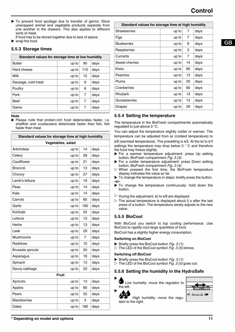
5.5.3 Storage timesStandard values for storage time at low humidity
Butter up to 90 daysHard cheese up to 110 daysMilk up to 12 daysSausage, cold meat up to 9 daysPoultry up to 6 daysPork up to 7 daysBeef up to 7 daysGame up to 7 days
Noteu Please note that protein-rich food deteriorates faster, i.e.
shellfish and crustaceans deteriorate faster than fish, fishfaster than meat.
Standard values for storage time at high humidityVegetables, salad
Artichokes up to 14 daysCelery up to 28 daysCauliflower up to 21 daysBroccoli up to 13 daysChicory up to 27 daysLamb's lettuce up to 19 daysPeas up to 14 daysKale up to 14 daysCarrots up to 80 daysGarlic up to 160 daysKohlrabi up to 55 daysLettuce up to 13 daysHerbs up to 13 daysLeek up to 29 daysMushrooms up to 7 daysRadishes up to 10 daysBrussels sprouts up to 20 daysAsparagus up to 18 daysSpinach up to 13 daysSavoy cabbage up to 20 days
FruitApricots up to 13 daysApples up to 80 daysPears up to 55 daysBlackberries up to 3 daysDates up to 180 days
Standard values for storage time at high humidityStrawberries up to 7 daysFigs up to 7 daysBlueberries up to 9 daysRaspberries up to 3 daysCurrants up to 7 daysSweet cherries up to 14 daysKiwis up to 80 daysPeaches up to 13 daysPlums up to 20 daysCranberries up to 60 daysRhubarb up to 13 daysGooseberries up to 13 daysGrapes up to 29 days
5.5.4 Setting the temperatureThe temperature in the BioFresh compartmentis automaticallyregulated to just above 0 °C.You can adjust the temperature slightly colder or warmer. Thetemperature can be adjusted from b1 (coldest temperature) tob9 (warmest temperature). The presetting is b5. At the b1 to b4settings the temperature may drop below 0 ° C and thereforethe food may freeze slightly.u For a warmer temperature adjustment: press Up setting
button, BioFresh compartment Fig. 3 (3).u For a colder temperature adjustment: press Down setting
button, BioFresh compartment Fig. 3 (4).w When pressed the first time, the BioFresh temperature
display indicates the value so far.u To change the temperature in steps: briefly press the button.-or-u To change the temperature continuously: hold down the
button.w During the adjustment, b1 to b9 are displayed.w The actual temperature is displayed about 5 s after the last
press of a button. The temperature slowly adjusts to the newvalue.
5.5.5 BioCoolWith BioCool you switch to top cooling performance. UseBioCool to rapidly cool large quantities of food.BioCool has a slightly higher energy consumption.Switching on BioCoolu Briefly press the BioCool button Fig. 3 (1).w The LED of the BioCool symbol Fig. 3 (5) shines.Switching off BioCoolu Briefly press the BioCool button Fig. 3 (1).w The LED of the BioCool symbol Fig. 3 (5) goes out.
5.5.6 Setting the humidity in the HydroSafeu
Low humidity: move the regulator tothe left.
u
High humidity: move the regu-lator to the right.
Control
* Depending on model and options 11
5.5.7 Drawers
Fig. 13 u Pull out the drawer, lift it at the back and draw it forwards for
removal.u Push the rails in again!
Fig. 14 u Pull out the rails.u Attach the drawer to the rails and push it in until it engages
audibly at the back.
5.5.8 Humidity control plate
Fig. 15 u To remove the humidity control plate: Having removed the
drawers, carefully draw the plate forwards and lower it forremoval.
u To insert the humidity control plate: Insert the cover mould-ings of the plate into the rear holder Fig. 15 (1) from under-neath and engage them in the holder Fig. 15 (2) at the front.
5.6 Freezer compartmentYou can store frozen food, make ice cubes and freeze freshfood in the freezer compartment.
5.6.1 Freezing foodThe rating plate indicates the maximum quantity of fresh foodyou can freeze within 24 hours (see Appliance at a glance)under “Freezing capacity ... kg/24h”.The maximum load of frozen food for the drawers is 25 kg eachand for the shelves 35 kg each.
CAUTIONRisk of injury due to broken glass!Bottles and cans containing drinks may burst when beingfrozen. This applies particularly to sparkling drinks.u Do not freeze bottles and cans containing drinks!In order that the food is rapidly frozen through to the core, donot exceed the following quantities per pack:- Fruit, vegetables up to 1 kg- Meat up to 2.5 kgu Pack the food in portions in freezer bags, reusable plastic,
metal or aluminium containers.
5.6.2 Thawing food- in the refrigerator compartment- in a microwave oven- in a conventional or fan oven- at room temperature
u Food once thawed should be re-frozen only in exceptionalcases.
5.6.3 Setting the temperature in the freezercompartmentThe appliance is pre-set for normal operation.The temperature can be set between -16 °C and -26 °C, therecommended temperature is -18 °C.u To set the temperature higher: press Up button, freezer
compartment Fig. 3 (8).u To set the temperature lower: press Down button, freezer
compartment Fig. 3 (9).w When the button is pressed the first time, the previous value
is indicated in the temperature display of the freezercompartment.
u To change the temperature in 1 °C steps: briefly press thebutton.
-or-u To change the temperature continuously: hold down the
button.w The value is displayed flashing during the setting operation.w The actual temperature is displayed approx. 5 seconds after
the button is last pressed. The temperature graduallyadjusts to the new value.
5.6.4 SuperFrostWith this function you can freeze fresh food quicklythrough to the core. The appliance operates withmaximum refrigeration. The noise of the refrigerationunit may be temporarily louder as a result.The maximum amount of fresh food which can be frozen in 24h is indicated on the type plate under “freezing capacity ... kg/24h”. This amount varies according to the model and climaterating.You have to activate SuperFrost in good time, depending onhow much fresh food is to be frozen: about 6 hours beforeplacing the food inside in case of small amounts and about 24hours in advance in case of the maximum amount of food to befrozen.Wrap produce and spread it out as far as possible. Do notallow produce to be frozen to touch produce that is alreadyfrozen to prevent the latter thawing.You do not have to activate SuperFrost in the following cases:- when placing frozen food in the freezer- when freezing up to approx. 2 kg fresh food dailyFreezing with SuperFrostu Briefly press the SuperFrost button Fig. 3 (11) once.w The LED of the SuperFrost symbol Fig. 3 (19) shines.w The freezing temperature drops, the appliance operates with
the maximum cooling capacity.For a smaller quantity of produce to be frozen:
u wait approx. 6 h.u Place wrapped produce in the top drawers.
For the maximum quantity of produce to be frozen:u wait approx. 24 h.w SuperFrost is automatically deactivated. Depending on the
quantity placed inside, after 30 h at the earliest, 65 h at thelatest.
w The LED on the SuperFrost symbol Fig. 3 (19) extinguishesonce freezing is completed.
w The appliance continues to operate in the energy-saving,normal mode.
Control
12 * Depending on model and options
5.6.5 DrawersNoteThe energy consumption increases and the cooling perform-ance decreases if there is insufficient ventilation.For appliances with NoFrost:u Leave the bottom drawer in the appliance!u Always keep the air slits of the fan free at the rear wall!
u To store frozen food directly on the shelves: pull the drawerforwards and lift it out.
5.6.6 Shelvesu To remove the shelf: lift up at the front
and pull out.u To put the shelf back: simply push in as
far as it will go.
5.6.7 VarioSpaceApart from being able to removethe drawers, you can alsoremove the shelves, creatingspace for large items of frozenfood. Poultry, meat, large piecesof game and high bakery prod-ucts can be frozen in one pieceand prepared.u The maximum load of frozen
food for the drawers is 25 kgeach and for the shelves35 kg each.
5.6.8 Information system
Fig. 16 (1) Ready-made meals, ice
cream(4) Sausages, bread
(2) Pork, fish (5) Game, mushrooms(3) Fruit, vegetables (6) Poultry, beef/veal
The figures indicate the storage time in months for severaltypes of frozen food in each case. Storage times given areguide times.
5.6.9 Cold storage accumulatorsThe cold storage accumulators prevent the temperature fromrising too fast in the event of power failure.
Using cold storage accumulatorsu Place the cold storage accumula-
tors in the top freezer compart-ment to save space.
u Place the frozen cold storageaccumulators on the frozen foodin the upper front area of thefreezer compartment.
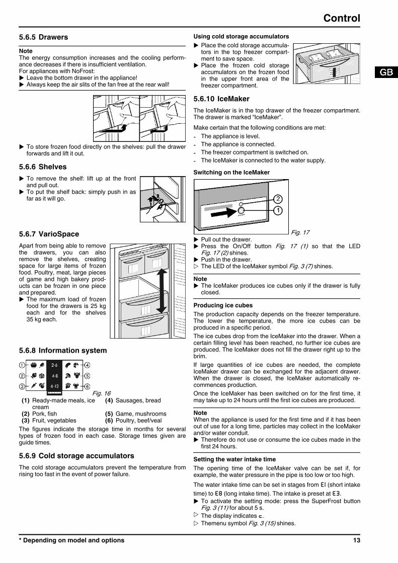
5.6.10 IceMakerThe IceMaker is in the top drawer of the freezer compartment.The drawer is marked “IceMaker”.Make certain that the following conditions are met:- The appliance is level.- The appliance is connected.- The freezer compartment is switched on.- The IceMaker is connected to the water supply.Switching on the IceMaker
Fig. 17 u Pull out the drawer.u Press the On/Off button Fig. 17 (1) so that the LED
Fig. 17 (2) shines.u Push in the drawer.w The LED of the IceMaker symbol Fig. 3 (7) shines.Noteu The IceMaker produces ice cubes only if the drawer is fully
closed.Producing ice cubesThe production capacity depends on the freezer temperature.The lower the temperature, the more ice cubes can beproduced in a specific period.The ice cubes drop from the IceMaker into the drawer. When acertain filling level has been reached, no further ice cubes areproduced. The IceMaker does not fill the drawer right up to thebrim.If large quantities of ice cubes are needed, the completeIceMaker drawer can be exchanged for the adjacent drawer.When the drawer is closed, the IceMaker automatically re-commences production.Once the IceMaker has been switched on for the first time, itmay take up to 24 hours until the first ice cubes are produced.NoteWhen the appliance is used for the first time and if it has beenout of use for a long time, particles may collect in the IceMakerand/or water conduit.u Therefore do not use or consume the ice cubes made in the
first 24 hours.Setting the water intake timeThe opening time of the IceMaker valve can be set if, forexample, the water pressure in the pipe is too low or too high.The water intake time can be set in stages from E1 (short intaketime) to E8 (long intake time). The intake is preset at E3.u To activate the setting mode: press the SuperFrost button
Fig. 3 (11) for about 5 s.w The display indicates c.w Themenu symbol Fig. 3 (15) shines.
Control
* Depending on model and options 13
u Using the Up setting button, freezer compartment Fig. 3 (8)and Down setting button, freezer compartment Fig. 3 (9)select E.
u To confirm: briefly press the SuperFrost button Fig. 3 (11).u To increase the water intake time: press the Up
setting button, freezer compartment Fig. 3 (8).u To reduce the water intake time: press the Down
setting button, freezer compartment Fig. 3 (9).u To confirm: press the SuperFrost button Fig. 3 (11).u To deactivate the setting mode: press the On/Off button,
freezer compartment Fig. 3 (10).-or-u Wait for 5 minutes.Switching off the IceMakerIf no ice cubes are needed, the IceMaker can be switched offindependently of the freezer compartment.When the IceMaker is switched off, the IceMaker drawer canalso be used for freezing and storing food.u Press the On/Off button for about 1 second until the LED
goes out.w The LED of the IceMaker symbol Fig. 3 (7) goes out.u Clean the IceMaker.w This ensures that no water or ice remains in the IceMaker.
6 Maintenance6.1 Defrosting with NoFrostThe NoFrost system automatically defrosts the appliance.BioFresh compartment:The defrost water evaporates due to the compressor heat.u Regularly clean the drain opening to allow the water to flow
away (see 6.2) .Freezer compartment:The moisture condenses on the evaporator, is periodicallydefrosted and evaporates.u The appliance does not have to be manually defrosted.
6.2 Cleaning the appliance
WARNINGRisk of injury and damage as a result of hot steam!Hot steam can lead to burns and can damage the surfaces.u Do not use any steam cleaners!
NOTICEIncorrect cleaning damages the appliance!u Do not use cleaning agents in concentrated form.u Do not use any scouring or abrasive sponges or steel wool.u Please do not use any aggressive, scouring, sand-,
chloride-, chemical- or acid-based cleaning agents.u Do not use chemical solvents.u Do not damage or remove the type plate on the inside of the
appliance. It is important for the customer service.u Do not pull off, bend or damage cables or other compo-
nents.u Do not allow any cleaning water to enter the drain channel,
ventilation grille or electrical parts.u Please use soft cleaning cloths and a universal pH-neutral
cleaning agent.u Please use cleaning and care products suitable for contact
with foodstuffs in the appliance interior.u Empty appliance.u Pull out the power plug.
u Clean plastic outer and inner surfaces with lukewarmwater and a little washing-up liquid.
Do not apply stainless steel cleaning agent to glass or plasticsurfaces to prevent them from being scratched. Darker areas atthe beginning and quite an intensive colour of the stainlesssteel surface are normal.NOTICEThe stainless steel doors are provided with a high-qualitysurface coating and must not be treated using the accompa-nying care product.
Otherwise the surface coating will be affected. u Wipe the coated door surfaces using a soft, clean cloth
only. In case of stubborn dirt, use a little water or a neutralcleaning agent. A microfibre cloth can be optionally used.
u If the stainless steel side walls are dirty, clean them usinga commercially available stainless steel cleaning agent.Then evenly apply the accompanying stainless steel careproduct, making strokes in the direction of the grain.
u Wipe side walls with a paint finish using a soft, cleancloth only. In case of stubborn dirt, use a little water or aneutral cleaning agent. A microfibre cloth can be optionallyused.
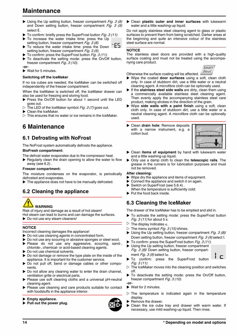
u Clean drain hole: Remove depositswith a narrow instrument, e.g. acotton bud.
u Clean items of equipment by hand with lukewarm waterand a little washing-up liquid.
u Only use a damp cloth to clean the telescopic rails. Thegrease in the runners is for lubrication purposes and mustnot be removed.
After cleaning:u Wipe dry the appliance and items of equipment.u Connect the appliance and switch it on again.u Switch on SuperFrost (see 5.6.4) .
When the temperature is sufficiently cold:u Put the food back inside.
6.3 Cleaning the IceMakerThe drawer of the IceMaker has to be emptied and slid in.u To activate the setting mode: press the SuperFrost button
Fig. 3 (11) for about 5 s.w The display indicates c.w The menu symbol Fig. 3 (15) shines.u Using the Up setting button, freezer compartment Fig. 3 (8)/
Down setting button, freezer compartment Fig. 3 (9) select I.u To confirm: press the SuperFrost button Fig. 3 (11).u Using the Up setting button, freezer compartment
Fig. 3 (8)/ Down setting button, freezer compart-ment Fig. 3 (9) select Ic.
u To confirm: press the SuperFrost buttonFig. 3 (11).
w The IceMaker moves into the cleaning position and switchesoff.
u To deactivate the setting mode: press the On/Off button,freezer compartment Fig. 3 (10).
-or-u Wait for 2 minutes.w The temperature is indicated again in the temperature
display.u Remove the drawer.u Clean the ice cube tray and drawer with warm water. If
necessary, use mild washing-up liquid. Then rinse.
Maintenance
14 * Depending on model and options
u Slide in the drawer again.If washing-up liquid was used:
u throw away the first three loads of ice cubes to get rid of anyremaining washing-up liquid.
Either leave the IceMaker switched off in this position or switchthe IceMaker on again (see 5.6.10) .
6.4 Customer serviceFirst check whether you can correct the fault yourself by refer-ence to the list (see Malfunction). If this is not the case, pleasecontact the customer service whose address is given in theenclosed customer service list.
WARNINGRisk of injury if repair work is not carried out professionally!u Have any repairs and action - not expressly specified - on
the appliance and mains cable carried out by servicepersonnel only. (see Maintenance)
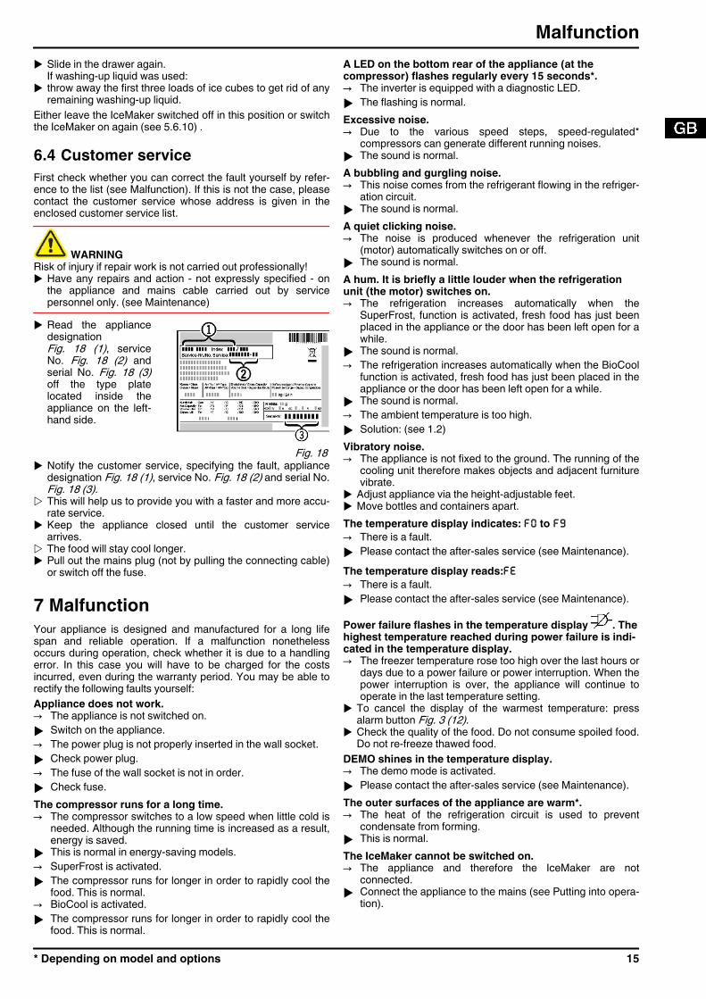
u Read the appliancedesignationFig. 18 (1), serviceNo. Fig. 18 (2) andserial No. Fig. 18 (3)off the type platelocated inside theappliance on the left-hand side.
Fig. 18 u Notify the customer service, specifying the fault, appliance
designation Fig. 18 (1), service No. Fig. 18 (2) and serial No.Fig. 18 (3).
w This will help us to provide you with a faster and more accu-rate service.
u Keep the appliance closed until the customer servicearrives.
w The food will stay cool longer.u Pull out the mains plug (not by pulling the connecting cable)
or switch off the fuse.
7 MalfunctionYour appliance is designed and manufactured for a long lifespan and reliable operation. If a malfunction nonethelessoccurs during operation, check whether it is due to a handlingerror. In this case you will have to be charged for the costsincurred, even during the warranty period. You may be able torectify the following faults yourself:Appliance does not work.→ The appliance is not switched on.u Switch on the appliance.→ The power plug is not properly inserted in the wall socket.u Check power plug.→ The fuse of the wall socket is not in order.u Check fuse.The compressor runs for a long time.→ The compressor switches to a low speed when little cold is
needed. Although the running time is increased as a result,energy is saved.
u This is normal in energy-saving models.→ SuperFrost is activated.u The compressor runs for longer in order to rapidly cool the
food. This is normal.→ BioCool is activated.u The compressor runs for longer in order to rapidly cool the
food. This is normal.
A LED on the bottom rear of the appliance (at thecompressor) flashes regularly every 15 seconds*.→ The inverter is equipped with a diagnostic LED.u The flashing is normal.Excessive noise.→ Due to the various speed steps, speed-regulated*
compressors can generate different running noises.u The sound is normal.A bubbling and gurgling noise.→ This noise comes from the refrigerant flowing in the refriger-
ation circuit.u The sound is normal.A quiet clicking noise.→ The noise is produced whenever the refrigeration unit
(motor) automatically switches on or off.u The sound is normal.A hum. It is briefly a little louder when the refrigerationunit (the motor) switches on.→ The refrigeration increases automatically when the
SuperFrost, function is activated, fresh food has just beenplaced in the appliance or the door has been left open for awhile.
u The sound is normal.→ The refrigeration increases automatically when the BioCool
function is activated, fresh food has just been placed in theappliance or the door has been left open for a while.
u The sound is normal.→ The ambient temperature is too high.u Solution: (see 1.2)Vibratory noise.→ The appliance is not fixed to the ground. The running of the
cooling unit therefore makes objects and adjacent furniturevibrate.
u Adjust appliance via the height-adjustable feet.u Move bottles and containers apart.The temperature display indicates: F0 to F9→ There is a fault.u Please contact the after-sales service (see Maintenance).The temperature display reads:FE→ There is a fault.u Please contact the after-sales service (see Maintenance).
Power failure flashes in the temperature display . Thehighest temperature reached during power failure is indi-cated in the temperature display.→ The freezer temperature rose too high over the last hours or
days due to a power failure or power interruption. When thepower interruption is over, the appliance will continue tooperate in the last temperature setting.
u To cancel the display of the warmest temperature: pressalarm button Fig. 3 (12).
u Check the quality of the food. Do not consume spoiled food.Do not re-freeze thawed food.
DEMO shines in the temperature display.→ The demo mode is activated.u Please contact the after-sales service (see Maintenance).The outer surfaces of the appliance are warm*.→ The heat of the refrigeration circuit is used to prevent
condensate from forming.u This is normal.The IceMaker cannot be switched on.→ The appliance and therefore the IceMaker are not
connected.u Connect the appliance to the mains (see Putting into opera-
tion).
Malfunction
* Depending on model and options 15
The IceMaker does not make any ice cubes.→ The IceMaker is not switched on.u Switch on the IceMaker.→ The drawer of the IceMaker is not properly closed.u Close the drawer properly.→ The water connection is not open.u Open the water connection.→ The water intake to the IceMaker has been interrupted.u Check the water connection (see Putting into operation).u Check the hosing (see Putting into operation).→ The screen located in the end piece of the water intake
hose or the screen located in the connecting piece on theappliance is blocked.
u Clean the screens.The temperature is not cold enough.→ The door of the appliance is not properly closed.u Close the door of the appliance.→ Insufficient ventilation.u Clear ventilation grilles.→ The ambient temperature is too high.u Solution: (see 1.2) .→ The appliance was opened too frequently or for too long.u Wait to see whether the appliance reaches the required
temperature by itself. If not, please contact the after salesservice (see Maintenance).
→ Too much fresh food was placed inside without SuperFrost.u Solution: (see 5.6.4)→ The temperature is incorrectly set.u Set the temperature to a colder setting and check after 24
hours.→ The appliance is too close to a source of heat (stove, heater
etc).u Change the position of the appliance or the source of heat.The interior light is not on.→ The appliance is not switched on.u Switch on the appliance.→ The door was open longer than 15 min.u The interior light automatically switches off if the door has
been open for about 15 min.→ The LED illumination is defective or the cover is damaged:
WARNINGRisk of injury due to electric shock!Live parts are located under the cover.u Have the LED interior light changed or repaired only by the
customer service or by specialized personnel trained for thepurpose.
WARNINGDanger of injury by LED lamp!The light intensity of the LED illumination corresponds to laserclass 1/1M.If the cover is defective:u Do not look into the illumination with optical lenses from the
immediate proximity. This can cause injury to the eyes.
8 Decommissioning8.1 Switching off the applianceNoteu To switch off the entire appliance it is necessary only to
switch off the freezer compartment.
8.1.1 Switching off the freezer compartmentu Press the freezer compartment On/Off button
Fig. 3 (10) for approx. 2 seconds.w The temperature displays are dark. The appli-
ance is switched off.
8.1.2 Switching off the BioFresh compartmentu Press BioFresh compartment On/Off button Fig. 3 (2) for
approx. 2 seconds.w The temperature display of the BioFresh compartment
Fig. 3 (6) is dark. The BioFresh compartment is switched off.
8.2 Taking the appliance out of serviceu Empty the appliance.u Put the IceMaker in the cleaning position (see Mainte-
nance).u Pull out the power plug.u Clean the appliance (see 6.2) .
u Leave the door open to prevent odour.
9 Disposing of the applianceThe appliance contains some reusable materialsand should be disposed of properly - not simplywith unsorted household refuse. Appliances whichare no longer needed must be disposed of in aprofessional and appropriate way, in accordancewith the current local regulations and laws.When disposing of the appliance, ensure that the refrigerationcircuit is not damaged to prevent uncontrolled escape of therefrigerant it contains (data on type plate) and oil.u Disable the appliance.u Pull out the plug.u Cut through the connecting cable.
Decommissioning
16 * Depending on model and options
Disposing of the appliance
* Depending on model and options 17

Liebherr Hausgeräte Ochsenhausen GmbH * Memminger Strasse 77-79 * D-88416 Ochsenhausen * * www.liebherr.com
Operating and installation instructionsUpright refrigerator
281013 7085582 - 01SKes/Sk/K/Kes 36...42 ... 6
Contents1 Appliance at a glance............................................ 21.1 Description of appliance and equipment.................. 21.2 Range of appliance use............................................ 21.3 Conformity................................................................ 31.4 External dimensions of the appliance....................... 31.5 Saving energy.......................................................... 31.6 HomeDialog............................................................. 42 General safety information................................... 43 Controls and displays........................................... 53.1 Operating and control elements............................... 53.2 Temperature display................................................. 54 Putting into operation............................................ 54.1 Transporting the appliance....................................... 54.2 Installing the appliance............................................. 54.3 Changing over the door hinges................................ 64.4 Insertion into a row of kitchen units........................... 84.5 Disposing of packaging............................................ 84.6 Connecting the appliance......................................... 84.7 Switching on the appliance....................................... 85 Control.................................................................... 85.1 Brightness of the temperature display...................... 85.2 Child proofing........................................................... 95.3 Door alarm................................................................ 95.4 Food refrigeration..................................................... 95.5 Setting the temperature............................................ 95.6 SuperCool................................................................ 95.7 Fan........................................................................... 105.8 Shelves.................................................................... 105.9 Using the sectioned shelf......................................... 105.10 Door racks................................................................ 105.11 Removing the bottle holder....................................... 105.12 Vegetable bins......................................................... 116 Maintenance........................................................... 116.1 Cleaning the appliance............................................. 116.2 Customer service..................................................... 117 Malfunction............................................................. 128 Decommissioning.................................................. 128.1 Switching off the appliance....................................... 128.2 Taking the appliance out of service.......................... 129 Disposing of the appliance................................... 13
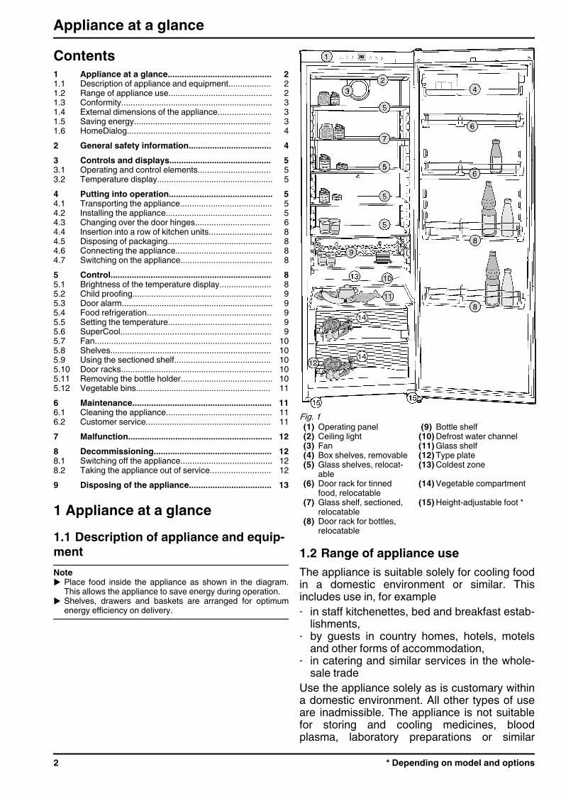
1 Appliance at a glance1.1 Description of appliance and equip-mentNoteu Place food inside the appliance as shown in the diagram.
This allows the appliance to save energy during operation.u Shelves, drawers and baskets are arranged for optimum
energy efficiency on delivery.
Fig. 1 (1) Operating panel (9) Bottle shelf(2) Ceiling light (10) Defrost water channel(3) Fan (11) Glass shelf(4) Box shelves, removable (12) Type plate(5) Glass shelves, relocat-
able(13) Coldest zone
(6) Door rack for tinnedfood, relocatable
(14) Vegetable compartment
(7) Glass shelf, sectioned,relocatable
(15) Height-adjustable foot *
(8) Door rack for bottles,relocatable
1.2 Range of appliance useThe appliance is suitable solely for cooling foodin a domestic environment or similar. Thisincludes use in, for example- in staff kitchenettes, bed and breakfast estab-
lishments,- by guests in country homes, hotels, motels
and other forms of accommodation,- in catering and similar services in the whole-
sale tradeUse the appliance solely as is customary withina domestic environment. All other types of useare inadmissible. The appliance is not suitablefor storing and cooling medicines, bloodplasma, laboratory preparations or similar
Appliance at a glance
2 * Depending on model and options
substances and products covered by the2007/47/EC Medical Devices Directive. Misuseof the appliance can result in the stored prod-ucts suffering harm or perishing. Furthermore,the appliance is not suitable for operation inpotentially explosive atmospheres.The appliance is set to operate within specificambient temperature limits according to itsclimate rating. The correct climate rating foryour appliance is indicated on the type plate.NoteuCompliance with the ambient temperatures
indicated is required, otherwise the coolingperformance is reduced.
Climaterating
for ambient temperatures of
SN 10 °C to 32 °CN 16 °C to 32 °CST 16 °C to 38 °CT 16 °C to 43 °C
1.3 ConformityThe refrigerant circuit is tested for leakage. The appliancecomplies with the relevant safety regulations and EC Directives2006/95/EC, 2004/108/EC, 2009/125/EC and 2010/30/EU.Note for test institutions:
Tests are to be carried out according to the applicablestandards and guidelines.Preparation and testing of the appliances must be carriedout taking the manufacturer's loading plans and thenotes in the operating manual into account.
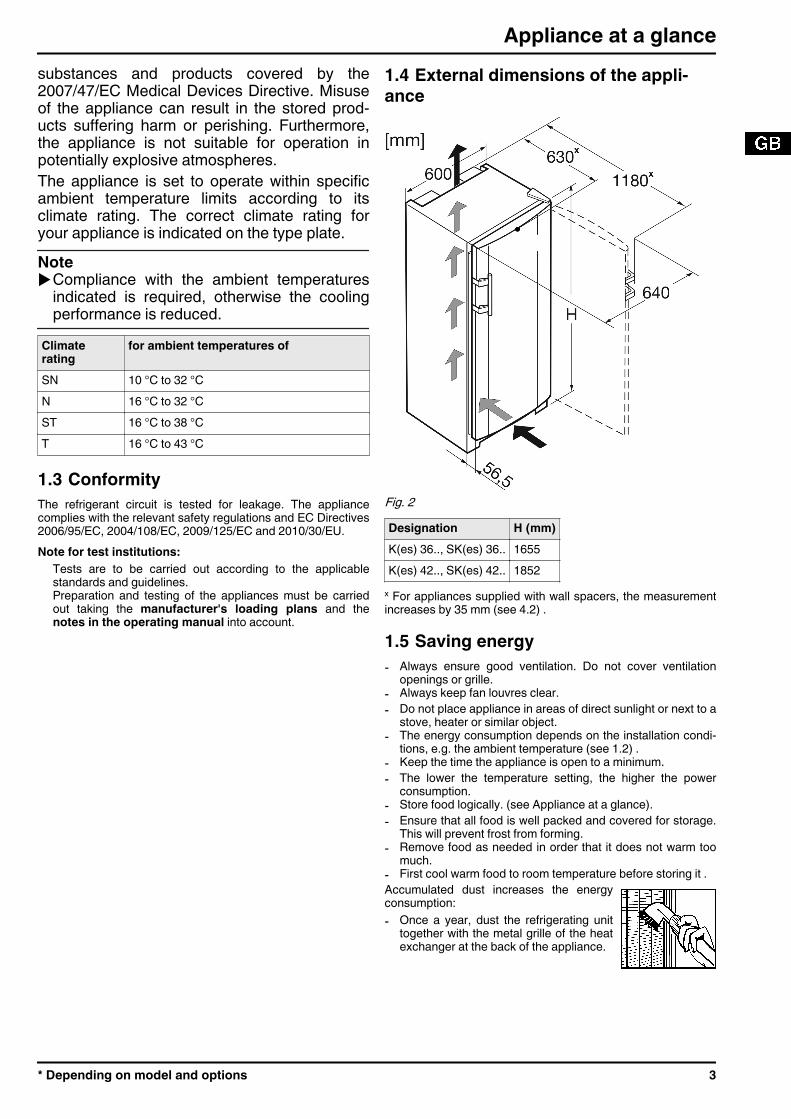
1.4 External dimensions of the appli-ance
Fig. 2 Designation H (mm)K(es) 36.., SK(es) 36.. 1655K(es) 42.., SK(es) 42.. 1852
x For appliances supplied with wall spacers, the measurementincreases by 35 mm (see 4.2) .
1.5 Saving energy- Always ensure good ventilation. Do not cover ventilation
openings or grille.- Always keep fan louvres clear.- Do not place appliance in areas of direct sunlight or next to a
stove, heater or similar object.- The energy consumption depends on the installation condi-
tions, e.g. the ambient temperature (see 1.2) .- Keep the time the appliance is open to a minimum.- The lower the temperature setting, the higher the power
consumption.- Store food logically. (see Appliance at a glance).- Ensure that all food is well packed and covered for storage.
This will prevent frost from forming.- Remove food as needed in order that it does not warm too
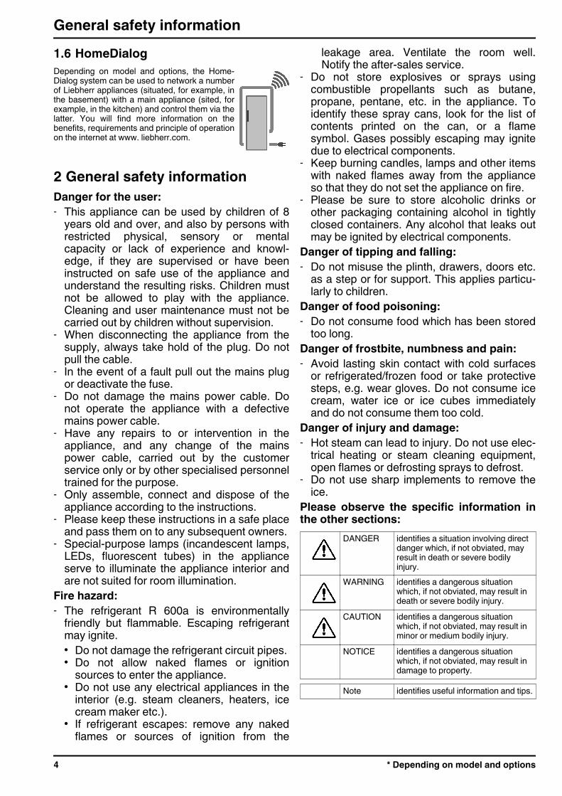
much.- First cool warm food to room temperature before storing it .Accumulated dust increases the energyconsumption:- Once a year, dust the refrigerating unit
together with the metal grille of the heatexchanger at the back of the appliance.
Appliance at a glance
* Depending on model and options 3
1.6 HomeDialogDepending on model and options, the Home-Dialog system can be used to network a numberof Liebherr appliances (situated, for example, inthe basement) with a main appliance (sited, forexample, in the kitchen) and control them via thelatter. You will find more information on thebenefits, requirements and principle of operationon the internet at www. liebherr.com.
2 General safety informationDanger for the user:- This appliance can be used by children of 8
years old and over, and also by persons withrestricted physical, sensory or mentalcapacity or lack of experience and knowl-edge, if they are supervised or have beeninstructed on safe use of the appliance andunderstand the resulting risks. Children mustnot be allowed to play with the appliance.Cleaning and user maintenance must not becarried out by children without supervision.
- When disconnecting the appliance from thesupply, always take hold of the plug. Do notpull the cable.
- In the event of a fault pull out the mains plugor deactivate the fuse.
- Do not damage the mains power cable. Donot operate the appliance with a defectivemains power cable.
- Have any repairs to or intervention in theappliance, and any change of the mainspower cable, carried out by the customerservice only or by other specialised personneltrained for the purpose.
- Only assemble, connect and dispose of theappliance according to the instructions.
- Please keep these instructions in a safe placeand pass them on to any subsequent owners.
- Special-purpose lamps (incandescent lamps,LEDs, fluorescent tubes) in the applianceserve to illuminate the appliance interior andare not suited for room illumination.
Fire hazard:- The refrigerant R 600a is environmentally
friendly but flammable. Escaping refrigerantmay ignite.• Do not damage the refrigerant circuit pipes.• Do not allow naked flames or ignition
sources to enter the appliance.• Do not use any electrical appliances in the
interior (e.g. steam cleaners, heaters, icecream maker etc.).
• If refrigerant escapes: remove any nakedflames or sources of ignition from the
leakage area. Ventilate the room well.Notify the after-sales service.
- Do not store explosives or sprays usingcombustible propellants such as butane,propane, pentane, etc. in the appliance. Toidentify these spray cans, look for the list ofcontents printed on the can, or a flamesymbol. Gases possibly escaping may ignitedue to electrical components.
- Keep burning candles, lamps and other itemswith naked flames away from the applianceso that they do not set the appliance on fire.
- Please be sure to store alcoholic drinks orother packaging containing alcohol in tightlyclosed containers. Any alcohol that leaks outmay be ignited by electrical components.
Danger of tipping and falling:- Do not misuse the plinth, drawers, doors etc.
as a step or for support. This applies particu-larly to children.
Danger of food poisoning:- Do not consume food which has been stored
too long.Danger of frostbite, numbness and pain:- Avoid lasting skin contact with cold surfaces
or refrigerated/frozen food or take protectivesteps, e.g. wear gloves. Do not consume icecream, water ice or ice cubes immediatelyand do not consume them too cold.
Danger of injury and damage:- Hot steam can lead to injury. Do not use elec-
trical heating or steam cleaning equipment,open flames or defrosting sprays to defrost.
- Do not use sharp implements to remove theice.
Please observe the specific information inthe other sections:
DANGER identifies a situation involving directdanger which, if not obviated, mayresult in death or severe bodilyinjury.
WARNING identifies a dangerous situationwhich, if not obviated, may result indeath or severe bodily injury.
CAUTION identifies a dangerous situationwhich, if not obviated, may result inminor or medium bodily injury.
NOTICE identifies a dangerous situationwhich, if not obviated, may result indamage to property.
Note identifies useful information and tips.
General safety information
4 * Depending on model and options
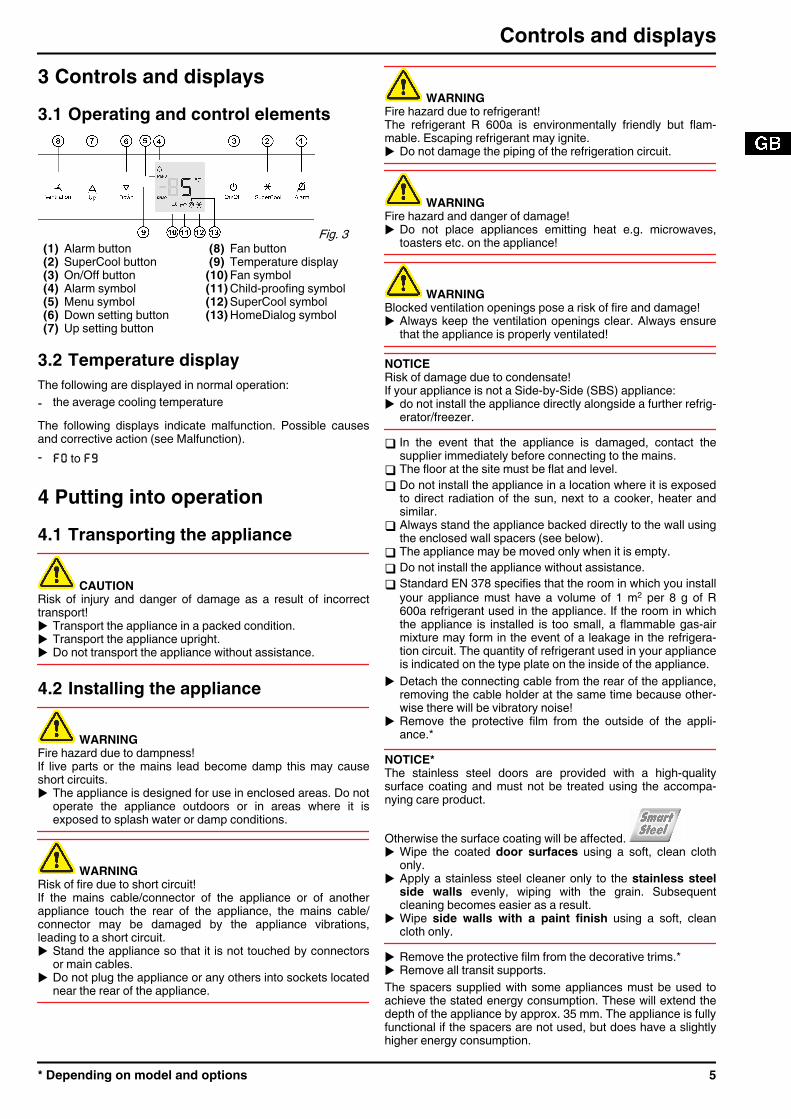
3 Controls and displays3.1 Operating and control elements
Fig. 3 (1) Alarm button (8) Fan button(2) SuperCool button (9) Temperature display(3) On/Off button (10) Fan symbol(4) Alarm symbol (11) Child-proofing symbol(5) Menu symbol (12) SuperCool symbol(6) Down setting button (13) HomeDialog symbol(7) Up setting button
3.2 Temperature displayThe following are displayed in normal operation:- the average cooling temperatureThe following displays indicate malfunction. Possible causesand corrective action (see Malfunction).- F0 to F9
4 Putting into operation4.1 Transporting the appliance
CAUTIONRisk of injury and danger of damage as a result of incorrecttransport!u Transport the appliance in a packed condition.u Transport the appliance upright.u Do not transport the appliance without assistance.
4.2 Installing the appliance
WARNINGFire hazard due to dampness!If live parts or the mains lead become damp this may causeshort circuits.u The appliance is designed for use in enclosed areas. Do not
operate the appliance outdoors or in areas where it isexposed to splash water or damp conditions.
WARNINGRisk of fire due to short circuit!If the mains cable/connector of the appliance or of anotherappliance touch the rear of the appliance, the mains cable/connector may be damaged by the appliance vibrations,leading to a short circuit.u Stand the appliance so that it is not touched by connectors
or main cables.u Do not plug the appliance or any others into sockets located
near the rear of the appliance.
WARNINGFire hazard due to refrigerant!The refrigerant R 600a is environmentally friendly but flam-mable. Escaping refrigerant may ignite.u Do not damage the piping of the refrigeration circuit.
WARNINGFire hazard and danger of damage!u Do not place appliances emitting heat e.g. microwaves,
toasters etc. on the appliance!
WARNINGBlocked ventilation openings pose a risk of fire and damage!u Always keep the ventilation openings clear. Always ensure
that the appliance is properly ventilated!
NOTICERisk of damage due to condensate!If your appliance is not a Side-by-Side (SBS) appliance:u do not install the appliance directly alongside a further refrig-
erator/freezer.
q In the event that the appliance is damaged, contact thesupplier immediately before connecting to the mains.
q The floor at the site must be flat and level.q Do not install the appliance in a location where it is exposed
to direct radiation of the sun, next to a cooker, heater andsimilar.
q Always stand the appliance backed directly to the wall usingthe enclosed wall spacers (see below).
q The appliance may be moved only when it is empty.q Do not install the appliance without assistance.q Standard EN 378 specifies that the room in which you install
your appliance must have a volume of 1 m2 per 8 g of R600a refrigerant used in the appliance. If the room in whichthe appliance is installed is too small, a flammable gas-airmixture may form in the event of a leakage in the refrigera-tion circuit. The quantity of refrigerant used in your applianceis indicated on the type plate on the inside of the appliance.
u Detach the connecting cable from the rear of the appliance,removing the cable holder at the same time because other-wise there will be vibratory noise!
u Remove the protective film from the outside of the appli-ance.*
NOTICE*The stainless steel doors are provided with a high-qualitysurface coating and must not be treated using the accompa-nying care product.
Otherwise the surface coating will be affected. u Wipe the coated door surfaces using a soft, clean cloth
only.u Apply a stainless steel cleaner only to the stainless steel
side walls evenly, wiping with the grain. Subsequentcleaning becomes easier as a result.
u Wipe side walls with a paint finish using a soft, cleancloth only.
u Remove the protective film from the decorative trims.*u Remove all transit supports.The spacers supplied with some appliances must be used toachieve the stated energy consumption. These will extend thedepth of the appliance by approx. 35 mm. The appliance is fullyfunctional if the spacers are not used, but does have a slightlyhigher energy consumption.
Controls and displays
* Depending on model and options 5
u In the case of an appliance withenclosed wall spacers, mount thewall spacers on the back of theappliance at the top left and right.
u Dispose of packaging material (see 4.5) .u Align the appliance so that it
stands firmly and on a level byapplying the accompanyingspanner to the adjustable-height feet (A) and using aspirit level.
u Then support the door: Extendthe adjustable foot at the turnhinge (B) until it rests on thefloor and then make a further90° turn.
When a Side-by-Side appliance (S…) is fitted together witha second appliance (as a SBS combination):
u Proceed according to the Side-by-Side combined fridge-freezer installation instructions. (Accessories bag of the SBSfreezer/appliance with freezer compartment)
Noteu Clean the appliance (see 6.1) .If the appliance is installed in a very damp environment,condensate may form on the outside of the appliance.u Always see to good ventilation at the installation site.
4.3 Changing over the door hingesYou can change over the door hinges if necessary.NOTICERisk of damage to side-by-side appliances due to condensa-tion!When a side-by-side appliance (S…) is fitted together with asecond appliance (as a SBS combination), the door hingesmust remain as delivered.u Do not change over the door hinges.Ensure that the following tools are to hand:q Torx® 25q Torx® 15q Screwdriverq Battery-powered screwdriver, if necessaryq Second person for fitting work, if neededq Accompanying Allen key size 2*
4.3.1 Detaching the doorNoteu Remove any food from the door racks before removing the
door, so that no food falls out.
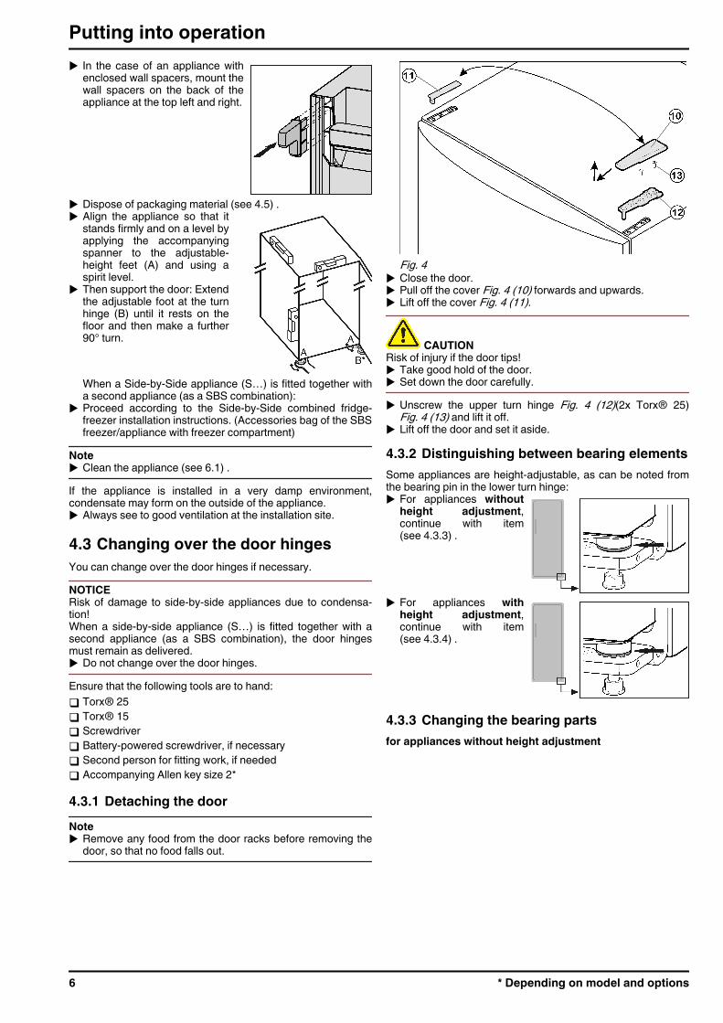
Fig. 4 u Close the door.u Pull off the cover Fig. 4 (10) forwards and upwards.u Lift off the cover Fig. 4 (11).
CAUTIONRisk of injury if the door tips!u Take good hold of the door.u Set down the door carefully.u Unscrew the upper turn hinge Fig. 4 (12)(2x Torx® 25)
Fig. 4 (13) and lift it off.u Lift off the door and set it aside.
4.3.2 Distinguishing between bearing elementsSome appliances are height-adjustable, as can be noted fromthe bearing pin in the lower turn hinge:u For appliances without
height adjustment,continue with item(see 4.3.3) .
u For appliances withheight adjustment,continue with item(see 4.3.4) .
4.3.3 Changing the bearing partsfor appliances without height adjustment
Putting into operation
6 * Depending on model and options
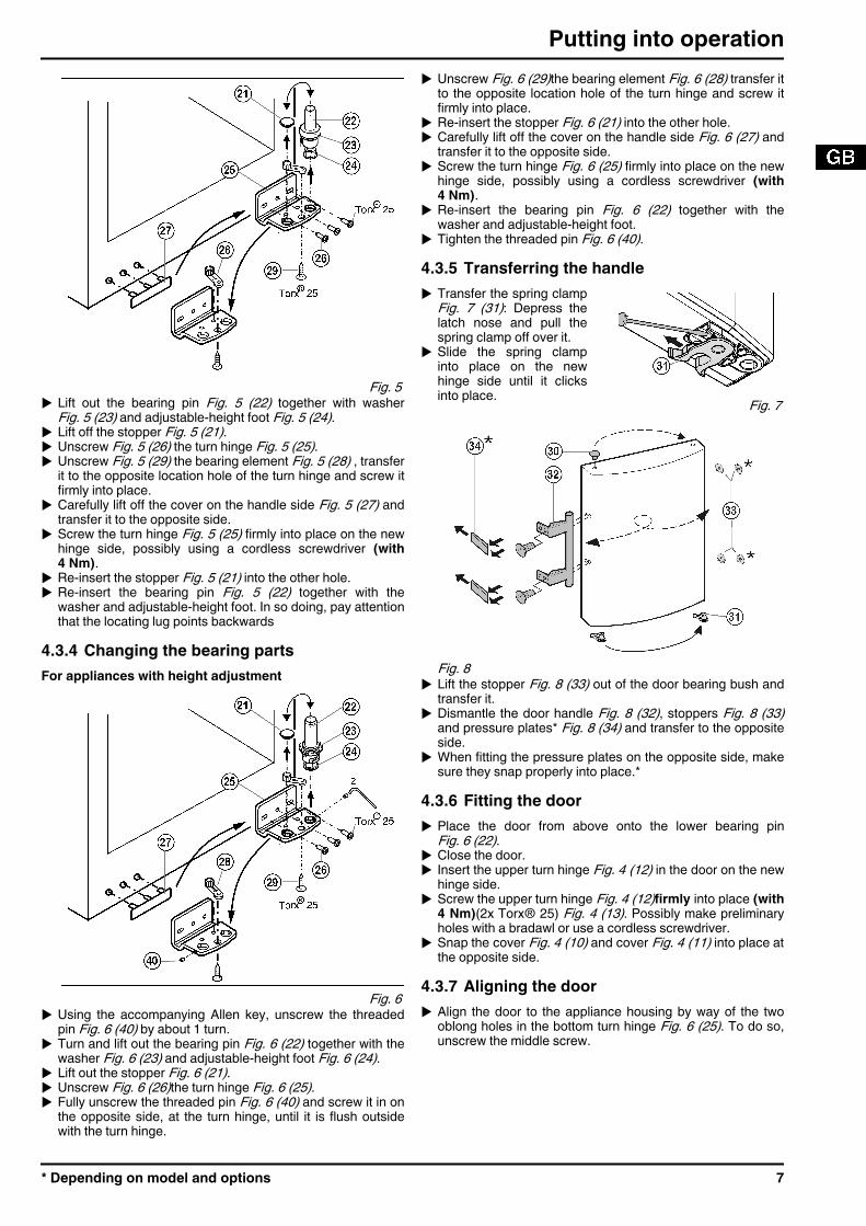
Fig. 5 u Lift out the bearing pin Fig. 5 (22) together with washer
Fig. 5 (23) and adjustable-height foot Fig. 5 (24).u Lift off the stopper Fig. 5 (21).u Unscrew Fig. 5 (26) the turn hinge Fig. 5 (25).u Unscrew Fig. 5 (29) the bearing element Fig. 5 (28) , transfer
it to the opposite location hole of the turn hinge and screw itfirmly into place.
u Carefully lift off the cover on the handle side Fig. 5 (27) andtransfer it to the opposite side.
u Screw the turn hinge Fig. 5 (25) firmly into place on the newhinge side, possibly using a cordless screwdriver (with4 Nm).
u Re-insert the stopper Fig. 5 (21) into the other hole.u Re-insert the bearing pin Fig. 5 (22) together with the
washer and adjustable-height foot. In so doing, pay attentionthat the locating lug points backwards
4.3.4 Changing the bearing partsFor appliances with height adjustment
Fig. 6 u Using the accompanying Allen key, unscrew the threaded
pin Fig. 6 (40) by about 1 turn.u Turn and lift out the bearing pin Fig. 6 (22) together with the
washer Fig. 6 (23) and adjustable-height foot Fig. 6 (24).u Lift out the stopper Fig. 6 (21).u Unscrew Fig. 6 (26)the turn hinge Fig. 6 (25).u Fully unscrew the threaded pin Fig. 6 (40) and screw it in on
the opposite side, at the turn hinge, until it is flush outsidewith the turn hinge.
u Unscrew Fig. 6 (29)the bearing element Fig. 6 (28) transfer itto the opposite location hole of the turn hinge and screw itfirmly into place.
u Re-insert the stopper Fig. 6 (21) into the other hole.u Carefully lift off the cover on the handle side Fig. 6 (27) and
transfer it to the opposite side.u Screw the turn hinge Fig. 6 (25) firmly into place on the new
hinge side, possibly using a cordless screwdriver (with4 Nm).
u Re-insert the bearing pin Fig. 6 (22) together with thewasher and adjustable-height foot.
u Tighten the threaded pin Fig. 6 (40).4.3.5 Transferring the handleu Transfer the spring clamp
Fig. 7 (31): Depress thelatch nose and pull thespring clamp off over it.
u Slide the spring clampinto place on the newhinge side until it clicksinto place. Fig. 7
Fig. 8 u Lift the stopper Fig. 8 (33) out of the door bearing bush and
transfer it.u Dismantle the door handle Fig. 8 (32), stoppers Fig. 8 (33)
and pressure plates* Fig. 8 (34) and transfer to the oppositeside.
u When fitting the pressure plates on the opposite side, makesure they snap properly into place.*
4.3.6 Fitting the dooru Place the door from above onto the lower bearing pin
Fig. 6 (22).u Close the door.u Insert the upper turn hinge Fig. 4 (12) in the door on the new
hinge side.u Screw the upper turn hinge Fig. 4 (12)firmly into place (with
4 Nm)(2x Torx® 25) Fig. 4 (13). Possibly make preliminaryholes with a bradawl or use a cordless screwdriver.
u Snap the cover Fig. 4 (10) and cover Fig. 4 (11) into place atthe opposite side.
4.3.7 Aligning the dooru Align the door to the appliance housing by way of the two
oblong holes in the bottom turn hinge Fig. 6 (25). To do so,unscrew the middle screw.
Putting into operation
* Depending on model and options 7
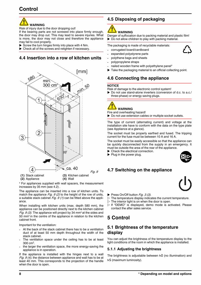
WARNINGRisk of injury due to the door dropping out!If the bearing parts are not screwed into place firmly enough,the door may drop out. This may lead to severe injuries. Whatis more, the door may not close and therefore the appliancemay fail to cool properly.u Screw the turn hinges firmly into place with 4 Nm.u Check all of the screws and retighten if necessary.
4.4 Insertion into a row of kitchen units
Fig. 9 (1) Stack cabinet (3) Kitchen cabinet(2) Appliance (4) Wall
x For appliances supplied with wall spacers, the measurementincreases by 35 mm (see 4.2) .The appliance can be inserted into a row of kitchen units. Tomatch the appliance Fig. 9 (2) to the height of the row of units,a suitable stack cabinet Fig. 9 (1) can be fitted above the appli-ance.When installing with kitchen units (max. depth 580 mm), theappliance can be positioned directly next to the kitchen cabinetFig. 9 (3). The appliance will project by 34 mmx at the sides and50 mmx in the centre of the appliance in relation to the kitchencabinet front.Important for the ventilation:- At the back of the stack cabinet there has to be a ventilation
duct of at least 50 mm depth throughout the width of thestack cabinet.
- The ventilation space under the ceiling has to be at least300 cm2.
- the larger the ventilation space, the more energy-saving theappliance is in operation.
If the appliance is installed with the hinges next to a wallFig. 9 (4), the distance between appliance and wall has to be atleast 40 mm. This corresponds to the projection of the handlewhen the door is open.
4.5 Disposing of packaging
WARNINGDanger of suffocation due to packing material and plastic film!u Do not allow children to play with packing material.The packaging is made of recyclable materials:- corrugated board/cardboard- expanded polystyrene parts- polythene bags and sheets- polypropylene straps- nailed wooden frame with polyethylene panel*u Take the packaging material to an official collecting point.
4.6 Connecting the applianceNOTICERisk of damage to the electronic control system!u Do not use stand-alone inverters (conversion of d.c. to a.c./
three-phase) or energy saving plugs.
WARNINGFire and overheating hazard!u Do not use extension cables or multiple socket outlets.The type of current (alternating current) and voltage at theinstallation site have to conform with the data on the type plate(see Appliance at a glance).The socket must be properly earthed and fused. The trippingcurrent for the fuse must be between 10 A and 16 A.The socket must be easily accessible so that the appliance canbe quickly disconnected from the supply in an emergency. Itmust be outside the area of the rear of the appliance.u Check the electrical connection.u Plug in the power plug.
4.7 Switching on the appliance
u Press On/Off button Fig. 3 (3).w The temperature display indicates the current temperature.w The interior light is on when the door is open.w If “DEMO” is displayed, demo mode is activated. Please
contact the after sales service.
5 Control5.1 Brightness of the temperaturedisplayYou can adjust the brightness of the temperature display to thelight conditions of the room in which the appliance is installed.
5.1.1 Adjusting the brightnessThe brightness is adjustable between h0 (no illumination) andh5 (maximum luminosity).
Control
8 * Depending on model and options
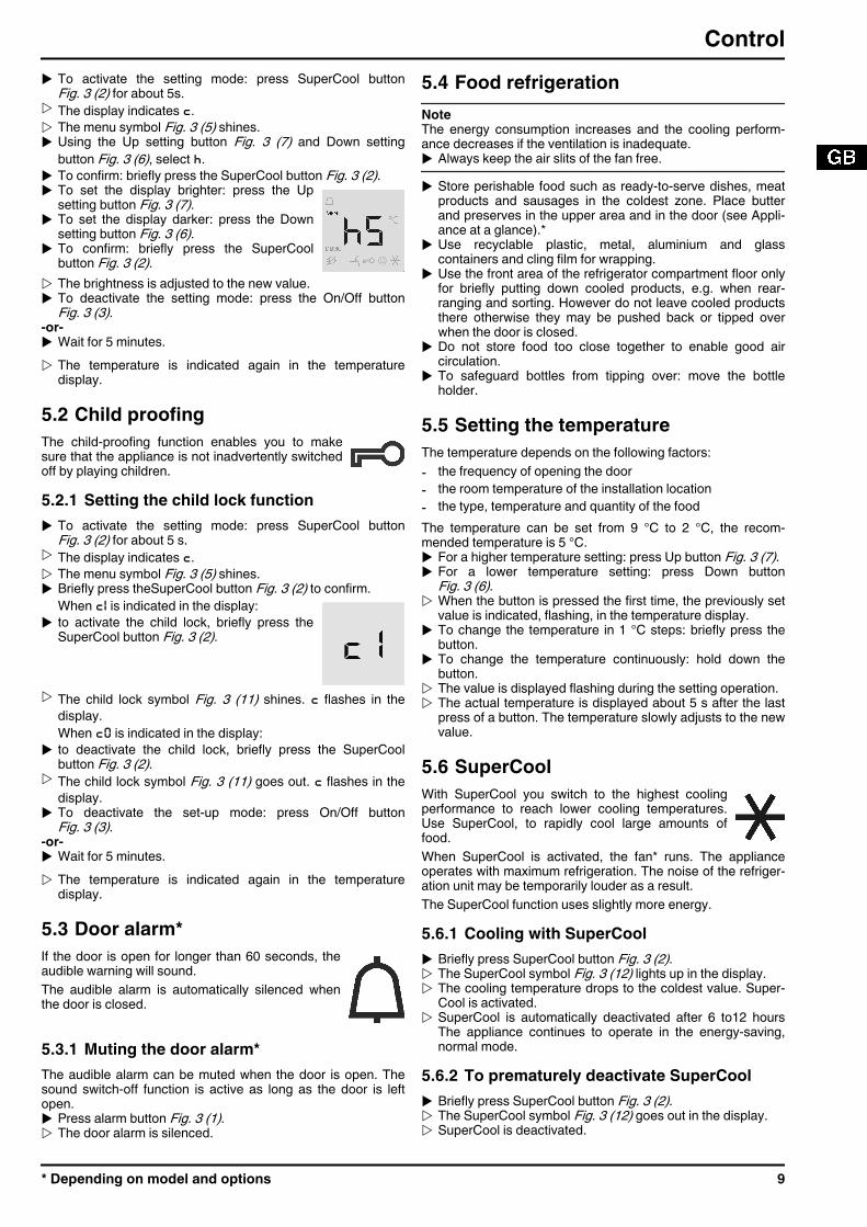
u To activate the setting mode: press SuperCool buttonFig. 3 (2) for about 5s.
w The display indicates c.w The menu symbol Fig. 3 (5) shines.u Using the Up setting button Fig. 3 (7) and Down setting
button Fig. 3 (6), select h.u To confirm: briefly press the SuperCool button Fig. 3 (2).u To set the display brighter: press the Up
setting button Fig. 3 (7).u To set the display darker: press the Down
setting button Fig. 3 (6).u To confirm: briefly press the SuperCool
button Fig. 3 (2).w The brightness is adjusted to the new value.u To deactivate the setting mode: press the On/Off button
Fig. 3 (3).-or-u Wait for 5 minutes.w The temperature is indicated again in the temperature
display.
5.2 Child proofingThe child-proofing function enables you to makesure that the appliance is not inadvertently switchedoff by playing children.
5.2.1 Setting the child lock functionu To activate the setting mode: press SuperCool button
Fig. 3 (2) for about 5 s.w The display indicates c.w The menu symbol Fig. 3 (5) shines.u Briefly press theSuperCool button Fig. 3 (2) to confirm.
When c1 is indicated in the display:u to activate the child lock, briefly press the
SuperCool button Fig. 3 (2).
w The child lock symbol Fig. 3 (11) shines. c flashes in thedisplay.When c0 is indicated in the display:
u to deactivate the child lock, briefly press the SuperCoolbutton Fig. 3 (2).
w The child lock symbol Fig. 3 (11) goes out. c flashes in thedisplay.
u To deactivate the set-up mode: press On/Off buttonFig. 3 (3).
-or-u Wait for 5 minutes.w The temperature is indicated again in the temperature
display.
5.3 Door alarm*If the door is open for longer than 60 seconds, theaudible warning will sound.The audible alarm is automatically silenced whenthe door is closed.
5.3.1 Muting the door alarm*The audible alarm can be muted when the door is open. Thesound switch-off function is active as long as the door is leftopen.u Press alarm button Fig. 3 (1).w The door alarm is silenced.
5.4 Food refrigerationNoteThe energy consumption increases and the cooling perform-ance decreases if the ventilation is inadequate.u Always keep the air slits of the fan free.u Store perishable food such as ready-to-serve dishes, meat
products and sausages in the coldest zone. Place butterand preserves in the upper area and in the door (see Appli-ance at a glance).*
u Use recyclable plastic, metal, aluminium and glasscontainers and cling film for wrapping.
u Use the front area of the refrigerator compartment floor onlyfor briefly putting down cooled products, e.g. when rear-ranging and sorting. However do not leave cooled productsthere otherwise they may be pushed back or tipped overwhen the door is closed.
u Do not store food too close together to enable good aircirculation.
u To safeguard bottles from tipping over: move the bottleholder.
5.5 Setting the temperatureThe temperature depends on the following factors:- the frequency of opening the door- the room temperature of the installation location- the type, temperature and quantity of the foodThe temperature can be set from 9 °C to 2 °C, the recom-mended temperature is 5 °C.u For a higher temperature setting: press Up button Fig. 3 (7).u For a lower temperature setting: press Down button
Fig. 3 (6).w When the button is pressed the first time, the previously set
value is indicated, flashing, in the temperature display.u To change the temperature in 1 °C steps: briefly press the
button.u To change the temperature continuously: hold down the
button.w The value is displayed flashing during the setting operation.w The actual temperature is displayed about 5 s after the last
press of a button. The temperature slowly adjusts to the newvalue.
5.6 SuperCoolWith SuperCool you switch to the highest coolingperformance to reach lower cooling temperatures.Use SuperCool, to rapidly cool large amounts offood.When SuperCool is activated, the fan* runs. The applianceoperates with maximum refrigeration. The noise of the refriger-ation unit may be temporarily louder as a result.The SuperCool function uses slightly more energy.
5.6.1 Cooling with SuperCoolu Briefly press SuperCool button Fig. 3 (2).w The SuperCool symbol Fig. 3 (12) lights up in the display.w The cooling temperature drops to the coldest value. Super-
Cool is activated.w SuperCool is automatically deactivated after 6 to12 hours
The appliance continues to operate in the energy-saving,normal mode.
5.6.2 To prematurely deactivate SuperCoolu Briefly press SuperCool button Fig. 3 (2).w The SuperCool symbol Fig. 3 (12) goes out in the display.w SuperCool is deactivated.
Control
* Depending on model and options 9

5.7 FanWith the fan you can rapidly cool large quantities offresh food or achieve a relatively even distribution oftemperature across all the storage levels.
The forced-air cooling is to be recommended:- at high room temperature (above33 °C )- at high humidityThe forced-air cooling uses slightly more energy. To saveenergy, the fan switches off automatically when the door isopen.
5.7.1 Switching on the fanu Briefly press the fan button Fig. 3 (8).w The fan symbol Fig. 3 (10) shines.w The fan is active. It switches on automatically when the
compressor runs.
5.7.2 To switch off the fanu Briefly press the fan button Fig. 3 (8).w The fan symbol Fig. 3 (10) goes out.w The fan is switched off.
5.8 Shelves5.8.1 Relocating the shelvesThe shelves have stops preventing them from being uninten-tionally pulled out.u Lift the shelf and draw it out
forwards.u Insert shelf with the raised
edge pointing upwards atthe back.*
w The food does not freezeonto the rear wall.
*5.8.2 Dismantling shelvesu The shelves can be
dismantled for cleaning.
*
5.9 Using the sectioned shelf
Fig. 10 u The glass shelf with stop face (2) has to be at the back.
5.10 Door racks5.10.1 Moving the storage racku Remove storage rack according to
illustration.
The boxes can be removedand placed on the table as asingle unit.
Three small boxes are available through the customer serviceas optional equipment instead of one wide and one small box.Either one or both the boxes can be used. If particularly tallbottles are to be stored, hang only a single box above the bottlerack.u Re-positioning the boxes:
Lift them for removal and re-position them as required.
5.10.2 Dismantling door racks
Fig. 11
u The door racks can be dismantled for cleaning.
5.11 Removing the bottle holderu Always take hold of the bottle holder
on the plastic part.
Control
10 * Depending on model and options
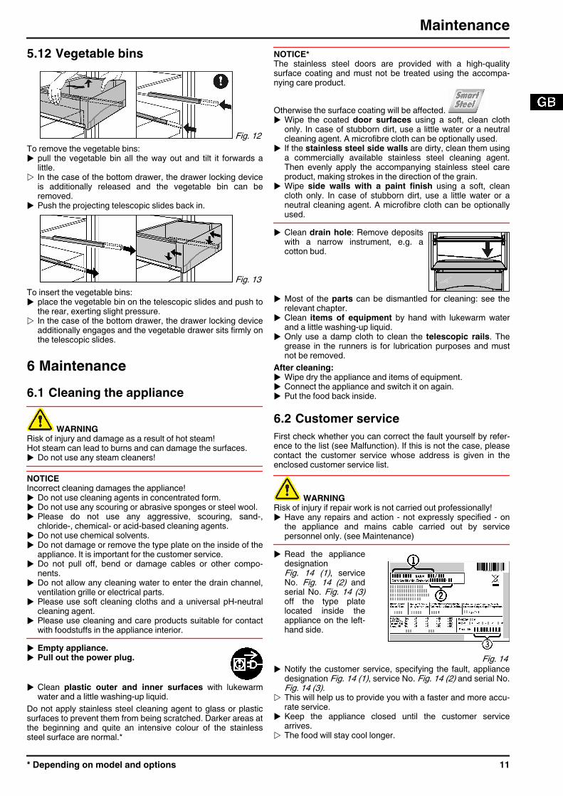
5.12 Vegetable bins
Fig. 12 To remove the vegetable bins:u pull the vegetable bin all the way out and tilt it forwards a
little.w In the case of the bottom drawer, the drawer locking device
is additionally released and the vegetable bin can beremoved.
u Push the projecting telescopic slides back in.
Fig. 13 To insert the vegetable bins:u place the vegetable bin on the telescopic slides and push to
the rear, exerting slight pressure.w In the case of the bottom drawer, the drawer locking device
additionally engages and the vegetable drawer sits firmly onthe telescopic slides.
6 Maintenance6.1 Cleaning the appliance
WARNINGRisk of injury and damage as a result of hot steam!Hot steam can lead to burns and can damage the surfaces.u Do not use any steam cleaners!
NOTICEIncorrect cleaning damages the appliance!u Do not use cleaning agents in concentrated form.u Do not use any scouring or abrasive sponges or steel wool.u Please do not use any aggressive, scouring, sand-,
chloride-, chemical- or acid-based cleaning agents.u Do not use chemical solvents.u Do not damage or remove the type plate on the inside of the
appliance. It is important for the customer service.u Do not pull off, bend or damage cables or other compo-
nents.u Do not allow any cleaning water to enter the drain channel,
ventilation grille or electrical parts.u Please use soft cleaning cloths and a universal pH-neutral
cleaning agent.u Please use cleaning and care products suitable for contact
with foodstuffs in the appliance interior.u Empty appliance.u Pull out the power plug.
u Clean plastic outer and inner surfaces with lukewarmwater and a little washing-up liquid.
Do not apply stainless steel cleaning agent to glass or plasticsurfaces to prevent them from being scratched. Darker areas atthe beginning and quite an intensive colour of the stainlesssteel surface are normal.*
NOTICE*The stainless steel doors are provided with a high-qualitysurface coating and must not be treated using the accompa-nying care product.
Otherwise the surface coating will be affected. u Wipe the coated door surfaces using a soft, clean cloth
only. In case of stubborn dirt, use a little water or a neutralcleaning agent. A microfibre cloth can be optionally used.
u If the stainless steel side walls are dirty, clean them usinga commercially available stainless steel cleaning agent.Then evenly apply the accompanying stainless steel careproduct, making strokes in the direction of the grain.
u Wipe side walls with a paint finish using a soft, cleancloth only. In case of stubborn dirt, use a little water or aneutral cleaning agent. A microfibre cloth can be optionallyused.
u Clean drain hole: Remove depositswith a narrow instrument, e.g. acotton bud.
u Most of the parts can be dismantled for cleaning: see therelevant chapter.
u Clean items of equipment by hand with lukewarm waterand a little washing-up liquid.
u Only use a damp cloth to clean the telescopic rails. Thegrease in the runners is for lubrication purposes and mustnot be removed.
After cleaning:u Wipe dry the appliance and items of equipment.u Connect the appliance and switch it on again.u Put the food back inside.
6.2 Customer serviceFirst check whether you can correct the fault yourself by refer-ence to the list (see Malfunction). If this is not the case, pleasecontact the customer service whose address is given in theenclosed customer service list.
WARNINGRisk of injury if repair work is not carried out professionally!u Have any repairs and action - not expressly specified - on
the appliance and mains cable carried out by servicepersonnel only. (see Maintenance)
u Read the appliancedesignationFig. 14 (1), serviceNo. Fig. 14 (2) andserial No. Fig. 14 (3)off the type platelocated inside theappliance on the left-hand side.
Fig. 14 u Notify the customer service, specifying the fault, appliance
designation Fig. 14 (1), service No. Fig. 14 (2) and serial No.Fig. 14 (3).
w This will help us to provide you with a faster and more accu-rate service.
u Keep the appliance closed until the customer servicearrives.
w The food will stay cool longer.
Maintenance
* Depending on model and options 11
u Pull out the mains plug (not by pulling the connecting cable)or switch off the fuse.
7 MalfunctionYour appliance is designed and manufactured for a long lifespan and reliable operation. If a malfunction nonethelessoccurs during operation, check whether it is due to a handlingerror. In this case you will have to be charged for the costsincurred, even during the warranty period. You may be able torectify the following faults yourself:Appliance does not work.→ The appliance is not switched on.u Switch on the appliance.→ The power plug is not properly inserted in the wall socket.u Check power plug.→ The fuse of the wall socket is not in order.u Check fuse.The compressor runs for a long time.→ The compressor switches to a low speed when little cold is
needed. Although the running time is increased as a result,energy is saved.
u This is normal in energy-saving models.→ SuperCool is activated.u The compressor runs for longer in order to rapidly cool the
food. This is normal.A LED on the bottom rear of the appliance (at thecompressor) flashes regularly every 15 seconds*.→ The inverter is equipped with a diagnostic LED.u The flashing is normal.Excessive noise.→ Due to the various speed steps, speed-regulated*
compressors can generate different running noises.u The sound is normal.A bubbling and gurgling noise.→ This noise comes from the refrigerant flowing in the refriger-
ation circuit.u The sound is normal.A quiet clicking noise.→ The noise is produced whenever the refrigeration unit
(motor) automatically switches on or off.u The sound is normal.A hum. It is briefly a little louder when the refrigerationunit (the motor) switches on.→ The refrigeration increases automatically when the Super-
Cool function is activated, fresh food has just been placedin the appliance or the door has been left open for a while.
u The sound is normal.→ The ambient temperature is too high.u Solution: (see 1.2)A low hum.→ The sound is produced by air flow noise of the fan.u The sound is normal.Vibratory noise.→ The appliance is not fixed to the ground. The running of the
cooling unit therefore makes objects and adjacent furniturevibrate.
u Adjust appliance via the height-adjustable feet.u Move bottles and containers apart.The temperature display indicates: F0 to F9→ There is a fault.u Please contact the after-sales service (see Maintenance).DEMO shines in the temperature display.→ The demo mode is activated.u Please contact the after-sales service (see Maintenance).
The outer surfaces of the appliance are warm*.→ The heat of the refrigeration circuit is used to prevent
condensate from forming.u This is normal.The temperature is not cold enough.→ The door of the appliance is not properly closed.u Close the door of the appliance.→ Insufficient ventilation.u Clear ventilation grilles.→ The ambient temperature is too high.u Solution: (see 1.2) .→ The appliance was opened too frequently or for too long.u Wait to see whether the appliance reaches the required
temperature by itself. If not, please contact the after salesservice (see Maintenance).
→ The temperature is incorrectly set.u Set the temperature to a colder setting and check after 24
hours.→ The appliance is too close to a source of heat (stove, heater
etc).u Change the position of the appliance or the source of heat.The interior light is not on.→ The appliance is not switched on.u Switch on the appliance.→ The door was open longer than 15 min.u The interior light automatically switches off if the door has
been open for about 15 min.→ The LED illumination is defective or the cover is damaged:
WARNINGRisk of injury due to electric shock!Live parts are located under the cover.u Have the LED interior light changed or repaired only by the
customer service or by specialized personnel trained for thepurpose.
WARNINGDanger of injury by LED lamp!The light intensity of the LED illumination corresponds to laserclass 1/1M.If the cover is defective:u Do not look into the illumination with optical lenses from the
immediate proximity. This can cause injury to the eyes.
8 Decommissioning8.1 Switching off the applianceu Press On/Off button Fig. 3 (3) for
approx. 2 seconds.w The temperature display is dark.w If the appliance cannot be switched off, the child
lock function is active (see 5.2) .
8.2 Taking the appliance out of serviceu Empty the appliance.u Pull out the power plug.u Clean the appliance (see 6.1) .
u Leave the door open to prevent odour.
Malfunction
12 * Depending on model and options
9 Disposing of the applianceThe appliance contains some reusable materialsand should be disposed of properly - not simplywith unsorted household refuse. Appliances whichare no longer needed must be disposed of in aprofessional and appropriate way, in accordancewith the current local regulations and laws.
When disposing of the appliance, ensure that the refrigerationcircuit is not damaged to prevent uncontrolled escape of therefrigerant it contains (data on type plate) and oil.u Disable the appliance.u Pull out the plug.u Cut through the connecting cable.
Disposing of the appliance
* Depending on model and options 13
Disposing of the appliance
14 * Depending on model and options
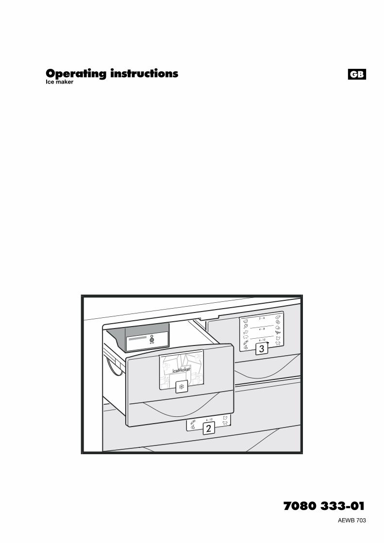
Operating instructionsIce maker
7080 333-01AEWB 703
GB
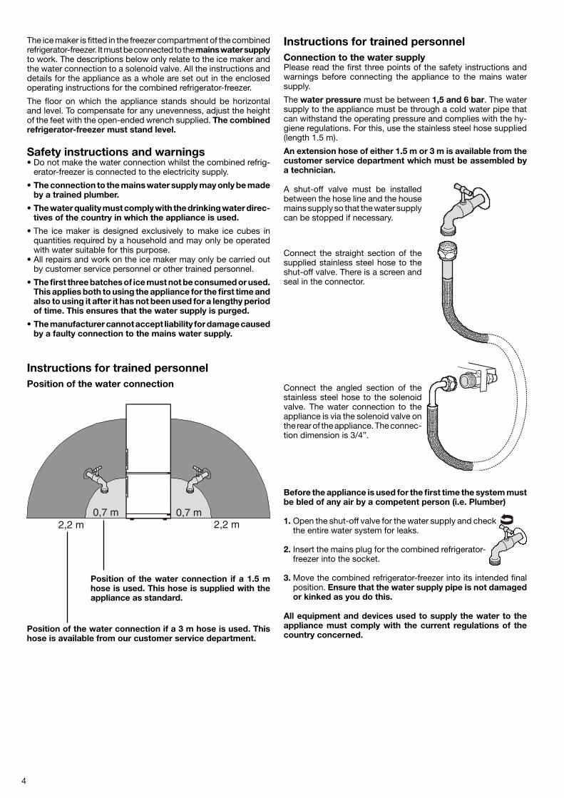
4
The ice maker is fitted in the freezer compartment of the combined refrigerator-freezer. It must be connected to the mains water supply to work. The descriptions below only relate to the ice maker and the water connection to a solenoid valve. All the instructions and details for the appliance as a whole are set out in the enclosed operating instructions for the combined refrigerator-freezer.
The floor on which the appliance stands should be horizontal and level. To compensate for any unevenness, adjust the height of the feet with the open-ended wrench supplied. The combined refrigerator-freezer must stand level.
Safety instructions and warnings• Do not make the water connection whilst the combined refrig-
erator-freezer is connected to the electricity supply.
• The connection to the mains water supply may only be made by a trained plumber.
• The water quality must comply with the drinking water direc-tives of the country in which the appliance is used.
• The ice maker is designed exclusively to make ice cubes in quantities required by a household and may only be operated with water suitable for this purpose.
• All repairs and work on the ice maker may only be carried out by customer service personnel or other trained personnel.
• The first three batches of ice must not be consumed or used. This applies both to using the appliance for the first time and also to using it after it has not been used for a lengthy period of time. This ensures that the water supply is purged.
• The manufacturer cannot accept liability for damage caused by a faulty connection to the mains water supply.
Instructions for trained personnelConnection to the water supplyPlease read the first three points of the safety instructions and warnings before connecting the appliance to the mains water supply.
The water pressure must be between 1,5 and 6 bar. The water supply to the appliance must be through a cold water pipe that can withstand the operating pressure and complies with the hy-giene regulations. For this, use the stainless steel hose supplied (length 1.5 m).
An extension hose of either 1.5 m or 3 m is available from the customer service department which must be assembled by a technician.
A shut-off valve must be installed between the hose line and the house mains supply so that the water supply can be stopped if necessary.
Before the appliance is used for the first time the system must be bled of any air by a competent person (i.e. Plumber)
1. Open the shut-off valve for the water supply and check the entire water system for leaks.
2. Insert the mains plug for the combined refrigerator-freezer into the socket.
3. Move the combined refrigerator-freezer into its intended final position. Ensure that the water supply pipe is not damaged or kinked as you do this.
All equipment and devices used to supply the water to the appliance must comply with the current regulations of the country concerned.
Connect the angled section of the stainless steel hose to the solenoid valve. The water connection to the appliance is via the solenoid valve on the rear of the appliance. The connec-tion dimension is 3/4”.
Instructions for trained personnelPosition of the water connection
Position of the water connection if a 1.5 m hose is used. This hose is supplied with the appliance as standard.
Position of the water connection if a 3 m hose is used. This hose is available from our customer service department.
Connect the straight section of the supplied stainless steel hose to the shut-off valve. There is a screen and seal in the connector.
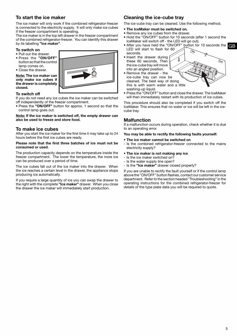
5
To start the ice makerThe ice maker will only work if the combined refrigerator-freezer is connected to the electricity supply. It will only make ice cubes if the freezer compartment is operating.The ice maker is in the top left drawer in the freezer compartment of the combined refrigerator-freezer. You can identify this drawer by its labelling ”Ice maker”.
To switch on• Pull out the drawer.• Press the ”ON/OFF”
button so that the control lamp comes on.
• Close the drawer.
Note: The ice maker can only make ice cubes if the drawer is completely closed.
To switch offIf you do not need any ice cubes the ice maker can be switched off independently of the freezer compartment.• Press the ”ON/OFF” button for approx. 1 second so that the
control lamp goes out.
Note: If the ice maker is switched off, the empty drawer can also be used to freeze and store food.
To make ice cubesAfter you start the ice maker for the first time it may take up to 24 hours before the first ice cubes are ready.
Please note that the first three batches of ice must not be consumed or used.
The production capacity depends on the temperature inside the freezer compartment. The lower the temperature, the more ice can be produced over a period of time.
The ice cubes fall out of the ice maker into the drawer. When the ice reaches a certain level in the drawer, the appliance stops producing ice automatically.
If you require a large quantity of ice you can swap the drawer to the right with the complete ”Ice maker” drawer. When you close the drawer the ice maker will immediately start production.
GB
MalfunctionIf a malfunction occurs during operation, check whether it is due to an operating error.
You may be able to rectify the following faults yourself:
• The ice maker cannot be switched on- Is the combined refrigerator-freezer connected to the mains
electricity supply?
• The ice maker is not making any ice- Is the ice maker switched on?- Is the water supply line open?- Is the ”Ice maker” drawer closed properly?
If you are unable to rectify the fault yourself or if the control lamp above the ”ON/OFF” button flashes, contact our customer service department. Refer to the section headed ”Troubleshooting” in the operating instructions for the combined refrigerator-freezer for details of the type plate data you will be required to quote.
Cleaning the ice-cube trayThe ice-cube tray can be cleaned. Use the following method.
• The IceMaker must be switched on.• Remove any ice cubes from the drawer.• Hold the ”ON/OFF” button for 10 seconds (after 1 second the
IceMaker will switch off - the LED will go out).• After you have held the ”ON/OFF” button for 10 seconds the
LED will start to flash for 60 seconds.
• Insert the drawer during these 60 seconds. Then the ice-cube tray will move into an angled position.
• Remove the drawer - the ice-cube tray can now be cleaned. The best way of doing this is with warm water and a little washing-up liquid.
• Press the ”ON/OFF” button and close the drawer. The IceMaker will then immediately restart with its production of ice cubes.
This procedure should also be completed if you switch off the IceMaker. This ensures that no water or ice will be left in the ice-cube tray.