Embed Size (px)
Citation preview

Operation (cont’d)
The Omniflo’s® modular design permits removal of theflowmeter’s sensing element (capsule) for maintenance.This feature also facilitates replacement of the capsulefor the purpose of obtaining a different flow range.
A Modulated Carrier (RF) or a Magnetic pickoff sensesthe rotation of the rotor and provides an electrical frequency output proportional to the process flow rate.The use of the RF pickoff optimizes the ability of themeter to measure minute flows since it does not produceany magnetic drag to the rotor motion, unlike magneticpickoffs.
The Omniflo’s® frequency output can be processed by complementary electronics, ranging from basic amplifiers, indicators and totalizers, to linearizers and more complex flow computers which compensatefor all measurable process parameters for ultimate volumetric or mass flow measurement accuracy.
Description
Flow Technology’s Omniflo® turbine flowmeter is a tangentialflow transducer capable of measuring very low flow rates in eitherliquid or gas with excellent speed of response and repeatability.
A high-resolution, volumetric flow sensing instrument, theOmniflo® offers repeatability which is better than ±0.1% in liquids and ±0.2% in gases. The flowmeter’s unique, tangentialrotor design allows it to operate effectively in low flow environ-ments where standard axial turbine meters cannot be used. Flow rates as low as 0.001 GPM (3.78 mLPM) in liquids and0.0015 ACFM (2.5 LPH) in gases can be measured. When pairedwith linearizing electronics, it is capable of overall accuracy of±0.25% in liquids and ±0.60% in gas.
The Omniflo’s® stainless steel construction makes it capable of withstanding pressures up to 400 BAR (5,800 psi). Optional configurations are available for higher operating pressures,dependent on end fittings.
ApplicationsThe Omniflo’s® low flow sensing capability makes it an effectiveinstrument for such low flow applications as fuel flow metering,mixing and blending of costly chemical additives, measuring of pharmaceutical products, purging of gases used in food packaging, liquid metering in automotive and aerospace applications, and numerous leak rate detection applications.
With its precision pivot sapphire bearing configuration, it canaccurately measure flow rates significantly lower than other available techniques. Ball bearing and sleeve (journal) bearingconfigurations are used for more rugged or less demanding flow rate applications.
OperationBased on its superior sensitivity to very low flows, the Omniflo®
depends on a precision orifice, located within the flowmeter sensing element (capsule), which directs fluid past the undersideof the tangential rotor. Since the rotor is freely suspended and of low mass, it responds almost instantaneously to changes in the process flow rate.
Features
• Operates in low flow ranges where standard axial turbine flowmeters cannot be used
• Accuracy of ±0.25% in liquids and ±0.60% in gas when paired with linearizing electronics
• Repeatability better than ±0.1% of reading in liquids and ±0.2% of reading in gas
• Measures flow rates as low as 0.001 GPM (3.78 mLPM)in liquids, and 0.0015 ACFM (2.5 LPH) in gas
• Standard configuration withstands pressures up to 400 BAR (5,800 psi), higher operating pressures are available, dependent on end fittings
• Compact size, 3" face-to-face with NPT or MS end connections
DimensionsSpecifications
Applicable to Both Liquid andGas FlowmetersMaterials Of Construction
Standard 316 SST Housing17-4 PH Rotor Teflon O-Ring15-7 Retaining Ring
Other materials of construction optional (see model number chart).
Operating Temp. Range Defined by bearing and pickoff selection(see below)
Bearing Type Temperature Limits:
Sapphire jewel pivot -60° F to 300° Fbearing, with tungsten (-50° C to 149° C)carbide shaft
Note: Standard maximum operating temperature of the jewel bearing is 300° F. Maximum operating temperatures up to 600° F are available as a special.
Ceramic journal -100° F to 800° Fbearing (-75° C to 425° C)
Tungsten carbide -60° F to 1200° Fjournal (-50° C to 650° C)
Ball bearing 440 C -450° F to 300° Fstainless steel (not (-270° C to 150° C)recommended forwater service)
Pickoff Type Temperature Limits:
Magnetic -430° F to 350° F(-260° C to 177° C)
High Temp. Magnetic -430° F to 750° F(-260° C to 400° C)
Modulated Carrier (RF) -300° F to 350° F(-185° C to 177° C)
High Temp. (RF) -300° F to 750° F(-185° C to 400° C)
Water CooledMag & RF Up to 1,100° F (593° C)
Pickoff Mating Electrical Connections
MS Connector2-pin, standard pickoff 15-89515-1013-pin, amplified pickoff 15-89515-1024-pin, pickoff with RTD 15-93825-01
Threaded Connection with LeadsJunction Box with Terminal 73-31836-105
Operating Pressure Range Defined by end connection selected. Pressures up to400 BAR (5,800 psi) are standard. Consult factoryfor higher pressures.
Filtration Recommendations 100 micron or better
Jewel/Journal Bearing10 micron or better Ball Bearing
Liquid ServicePerformance specifications are based on tests with waterat normal conditions (viscosity of 1.0 centistoke) withPivot Bearing.
Calibration Accuracy <±0.05% of reading or better(accuracy of primary flowcalibration standard directlytraceable to NIST)
Repeatability <±0.1% of reading
Linearity ±0.1% with linearizingelectronics
Pressure Drop Less than 700 mBAR (10 psid)at maximum flow rate
Viscosity Max. viscosity recommended 50 CST
Note: Universal viscosity calibrations may limit flow range(consult factory). Multiple viscosity calibrations available.
Gas ServicePerformance specifications are based on air at normal conditions 14.7 psia and 68° F (1 BAR and 20° C) with Pivot Bearing.
Calibration Accuracy <±0.3% of reading (accuracyof primary flow calibration standard directly traceable to NIST)
Repeatability <±0.2% of reading
Linearity ±0.1% with linearizing electronics
Pressure Drop Less than 20 mBAR (8 INWC) at maximum flow rate
Note: Universal Reynolds Number calibrations maylimit flow range (consult factory). Multiple ReynoldsNumber calibrations available.
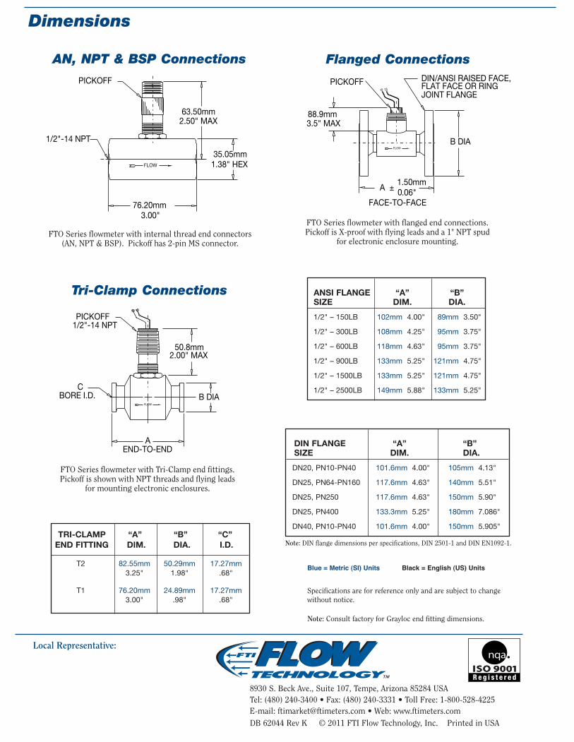
Blue = Metric (SI) Units Black = English (US) Units
DIN FLANGE “A” “B”SIZE DIM. DIA.
DN20, PN10-PN40 101.6mm 4.00" 105mm 4.13"
DN25, PN64-PN160 117.6mm 4.63" 140mm 5.51"
DN25, PN250 117.6mm 4.63" 150mm 5.90"
DN25, PN400 133.3mm 5.25" 180mm 7.086"
DN40, PN10-PN40 101.6mm 4.00" 150mm 5.905"
ANSI FLANGE “A” “B”SIZE DIM. DIA.
1/2" – 150LB 102mm 4.00" 89mm 3.50"
1/2" – 300LB 108mm 4.25" 95mm 3.75"
1/2" – 600LB 118mm 4.63" 95mm 3.75"
1/2" – 900LB 133mm 5.25" 121mm 4.75"
1/2" – 1500LB 133mm 5.25" 121mm 4.75"
1/2" – 2500LB 149mm 5.88" 133mm 5.25"
FTO Series flowmeter with flanged end connections.Pickoff is X-proof with flying leads and a 1" NPT spud
for electronic enclosure mounting.FTO Series flowmeter with internal thread end connectors
(AN, NPT & BSP). Pickoff has 2-pin MS connector.
FTO Series flowmeter with Tri-Clamp end fittings. Pickoff is shown with NPT threads and flying leads
for mounting electronic enclosures.
Omniflo®
Turbine Flowmeters
Omniflo®
Turbine Flowmeters
Local Representative:
8930 S. Beck Ave., Suite 107, Tempe, Arizona 85284 USATel: (480) 240-3400 • Fax: (480) 240-3331 • Toll Free: 1-800-528-4225E-mail: [email protected] • Web: www.ftimeters.comDB 62044 Rev K © 2011 FTI Flow Technology, Inc. Printed in USA
AN, NPT & BSP Connections Flanged Connections
Tri-Clamp Connections
TRI-CLAMP “A” “B” “C”
END FITTING DIM. DIA. I.D.
T2 82.55mm 50.29mm 17.27mm3.25" 1.98" .68"
T1 76.20mm 24.89mm 17.27mm3.00" .98" .68"
Note: Consult factory for Grayloc end fitting dimensions.
Note: DIN flange dimensions per specifications, DIN 2501-1 and DIN EN1092-1.
Specifications are for reference only and are subject to changewithout notice.

Operation (cont’d)
The Omniflo’s® modular design permits removal of theflowmeter’s sensing element (capsule) for maintenance.This feature also facilitates replacement of the capsulefor the purpose of obtaining a different flow range.
A Modulated Carrier (RF) or a Magnetic pickoff sensesthe rotation of the rotor and provides an electrical frequency output proportional to the process flow rate.The use of the RF pickoff optimizes the ability of themeter to measure minute flows since it does not produceany magnetic drag to the rotor motion, unlike magneticpickoffs.
The Omniflo’s® frequency output can be processed by complementary electronics, ranging from basic amplifiers, indicators and totalizers, to linearizers and more complex flow computers which compensatefor all measurable process parameters for ultimate volumetric or mass flow measurement accuracy.
Description
Flow Technology’s Omniflo® turbine flowmeter is a tangentialflow transducer capable of measuring very low flow rates in eitherliquid or gas with excellent speed of response and repeatability.
A high-resolution, volumetric flow sensing instrument, theOmniflo® offers repeatability which is better than ±0.1% in liquids and ±0.2% in gases. The flowmeter’s unique, tangentialrotor design allows it to operate effectively in low flow environ-ments where standard axial turbine meters cannot be used. Flow rates as low as 0.001 GPM (3.78 mLPM) in liquids and0.0015 ACFM (2.5 LPH) in gases can be measured. When pairedwith linearizing electronics, it is capable of overall accuracy of±0.25% in liquids and ±0.60% in gas.
The Omniflo’s® stainless steel construction makes it capable of withstanding pressures up to 400 BAR (5,800 psi). Optional configurations are available for higher operating pressures,dependent on end fittings.
ApplicationsThe Omniflo’s® low flow sensing capability makes it an effectiveinstrument for such low flow applications as fuel flow metering,mixing and blending of costly chemical additives, measuring of pharmaceutical products, purging of gases used in food packaging, liquid metering in automotive and aerospace applications, and numerous leak rate detection applications.
With its precision pivot sapphire bearing configuration, it canaccurately measure flow rates significantly lower than other available techniques. Ball bearing and sleeve (journal) bearingconfigurations are used for more rugged or less demanding flow rate applications.
OperationBased on its superior sensitivity to very low flows, the Omniflo®
depends on a precision orifice, located within the flowmeter sensing element (capsule), which directs fluid past the undersideof the tangential rotor. Since the rotor is freely suspended and of low mass, it responds almost instantaneously to changes in the process flow rate.
Features
• Operates in low flow ranges where standard axial turbine flowmeters cannot be used
• Accuracy of ±0.25% in liquids and ±0.60% in gas when paired with linearizing electronics
• Repeatability better than ±0.1% of reading in liquids and ±0.2% of reading in gas
• Measures flow rates as low as 0.001 GPM (3.78 mLPM)in liquids, and 0.0015 ACFM (2.5 LPH) in gas
• Standard configuration withstands pressures up to 400 BAR (5,800 psi), higher operating pressures are available, dependent on end fittings
• Compact size, 3" face-to-face with NPT or MS end connections
DimensionsSpecifications
Applicable to Both Liquid andGas FlowmetersMaterials Of Construction
Standard 316 SST Housing17-4 PH Rotor Teflon O-Ring15-7 Retaining Ring
Other materials of construction optional (see model number chart).
Operating Temp. Range Defined by bearing and pickoff selection(see below)
Bearing Type Temperature Limits:
Sapphire jewel pivot -60° F to 300° Fbearing, with tungsten (-50° C to 149° C)carbide shaft
Note: Standard maximum operating temperature of the jewel bearing is 300° F. Maximum operating temperatures up to 600° F are available as a special.
Ceramic journal -100° F to 800° Fbearing (-75° C to 425° C)
Tungsten carbide -60° F to 1200° Fjournal (-50° C to 650° C)
Ball bearing 440 C -450° F to 300° Fstainless steel (not (-270° C to 150° C)recommended forwater service)
Pickoff Type Temperature Limits:
Magnetic -430° F to 350° F(-260° C to 177° C)
High Temp. Magnetic -430° F to 750° F(-260° C to 400° C)
Modulated Carrier (RF) -300° F to 350° F(-185° C to 177° C)
High Temp. (RF) -300° F to 750° F(-185° C to 400° C)
Water CooledMag & RF Up to 1,100° F (593° C)
Pickoff Mating Electrical Connections
MS Connector2-pin, standard pickoff 15-89515-1013-pin, amplified pickoff 15-89515-1024-pin, pickoff with RTD 15-93825-01
Threaded Connection with LeadsJunction Box with Terminal 73-31836-105
Operating Pressure Range Defined by end connection selected. Pressures up to400 BAR (5,800 psi) are standard. Consult factoryfor higher pressures.
Filtration Recommendations 100 micron or better
Jewel/Journal Bearing10 micron or better Ball Bearing
Liquid ServicePerformance specifications are based on tests with waterat normal conditions (viscosity of 1.0 centistoke) withPivot Bearing.
Calibration Accuracy <±0.05% of reading or better(accuracy of primary flowcalibration standard directlytraceable to NIST)
Repeatability <±0.1% of reading
Linearity ±0.1% with linearizingelectronics
Pressure Drop Less than 700 mBAR (10 psid)at maximum flow rate
Viscosity Max. viscosity recommended 50 CST
Note: Universal viscosity calibrations may limit flow range(consult factory). Multiple viscosity calibrations available.
Gas ServicePerformance specifications are based on air at normal conditions 14.7 psia and 68° F (1 BAR and 20° C) with Pivot Bearing.
Calibration Accuracy <±0.3% of reading (accuracyof primary flow calibration standard directly traceable to NIST)
Repeatability <±0.2% of reading
Linearity ±0.1% with linearizing electronics
Pressure Drop Less than 20 mBAR (8 INWC) at maximum flow rate
Note: Universal Reynolds Number calibrations maylimit flow range (consult factory). Multiple ReynoldsNumber calibrations available.
Blue = Metric (SI) Units Black = English (US) Units
DIN FLANGE “A” “B”SIZE DIM. DIA.
DN20, PN10-PN40 101.6mm 4.00" 105mm 4.13"
DN25, PN64-PN160 117.6mm 4.63" 140mm 5.51"
DN25, PN250 117.6mm 4.63" 150mm 5.90"
DN25, PN400 133.3mm 5.25" 180mm 7.086"
DN40, PN10-PN40 101.6mm 4.00" 150mm 5.905"
ANSI FLANGE “A” “B”SIZE DIM. DIA.
1/2" – 150LB 102mm 4.00" 89mm 3.50"
1/2" – 300LB 108mm 4.25" 95mm 3.75"
1/2" – 600LB 118mm 4.63" 95mm 3.75"
1/2" – 900LB 133mm 5.25" 121mm 4.75"
1/2" – 1500LB 133mm 5.25" 121mm 4.75"
1/2" – 2500LB 149mm 5.88" 133mm 5.25"
FTO Series flowmeter with flanged end connections.Pickoff is X-proof with flying leads and a 1" NPT spud
for electronic enclosure mounting.FTO Series flowmeter with internal thread end connectors
(AN, NPT & BSP). Pickoff has 2-pin MS connector.
FTO Series flowmeter with Tri-Clamp end fittings. Pickoff is shown with NPT threads and flying leads
for mounting electronic enclosures.
Omniflo®
Turbine Flowmeters
Omniflo®
Turbine Flowmeters
Local Representative:
8930 S. Beck Ave., Suite 107, Tempe, Arizona 85284 USATel: (480) 240-3400 • Fax: (480) 240-3331 • Toll Free: 1-800-528-4225E-mail: [email protected] • Web: www.ftimeters.comDB 62044 Rev K © 2011 FTI Flow Technology, Inc. Printed in USA
AN, NPT & BSP Connections Flanged Connections
Tri-Clamp Connections
TRI-CLAMP “A” “B” “C”
END FITTING DIM. DIA. I.D.
T2 82.55mm 50.29mm 17.27mm3.25" 1.98" .68"
T1 76.20mm 24.89mm 17.27mm3.00" .98" .68"
Note: Consult factory for Grayloc end fitting dimensions.
Note: DIN flange dimensions per specifications, DIN 2501-1 and DIN EN1092-1.
Specifications are for reference only and are subject to changewithout notice.

Abbreviations for Units of Measure:
mLPM = Milliliters per MinuteGPM = Gallons per Minute
ALPH = Actual Liters per HourACFM = Actual Cubic Feet per Minute
P/L = Pulses per LiterP/G = Pulses per Gallon
P/Ft3 = Pulses per Cubic FootP/mL = Pulses per Milliliter
NORMAL 10:1FLOW RANGE
GA
SLI
QU
ID
EXTENDEDFLOW RANGE
LIQ
UID
& G
AS
Notes: 1) Some combinations may be less than 10:1.2) Meters using magnetic pickoffs may have single digit mv amplitude readings at the low flow rate.
Model Numbering System
Blue = Metric (SI) Units Black = English (US) UnitsMetric units in mLPM (liquid) English units in GPM (liquid) & ALPH (gas) & ACFM (gas)
FTO Sizing
Bearing selection will affect flow range. Refer to sizing specification table for correct flow ranges.
C = SAPPHIRE PIVOT (Sapphire pivot, Carbide shaft)A = BALL BEARING (440 C balls, 316 shaft)D = CARBIDE JOURNAL (Carbide sleeve and shaft) liquid onlyE = GRAPHITE JOURNAL (Graphite sleeve, 316 shaft) liquid onlyG = CERAMIC JOURNAL (Ceramic sleeve and shaft) liquid only
Bearings
Pickoffs-1 = Modulated Carrier, MS connector-2 = Magnetic, MS connector-3 = Magnetic, flying leads/threaded connection-5 = Modulated Carrier, flying leads/threaded connection-6 = Magnetic, MS connector, 400° C (750° F) max.-7 = Magnetic, flying leads/threaded connection, 400° C (750° F) max.-L = Modulated Carrier, MS connector, 400° C (750° F) max.-M = Modulated Carrier, flying leads/threaded connection
400° C (750° F) max.-8 = Modulated Carrier, MS connector, 11/16" thread, 330 µH coil-9 = Modulated Carrier, MS connector, 5/8" – 18 thread, 330 µH coil-Y = Modulated Carrier, CSA X-Proof -Z = Magnetic, CSA X-ProofT1 = Modulated Carrier w/RTD, MS connectorT2 = Magnetic w/RTD, MS connectorT3 = Magnetic w/RTD, flying leads/threaded connectionT5 = Modulated Carrier w/RTD, flying leads/threaded connection-X = Modulated Carrier, I.S. approved, MS connectorSS = Modulated Carrier, I.S. approved, flying leads/smooth bodyXX = Modulated Carrier, I.S. approved, flying leads/threaded body-U = Magnetic, I.S. approved, MS connectorPP = Magnetic, I.S. approved, flying leads/smooth bodyTT = Magnetic, I.S. approved, flying leads/threaded body
Notes: 1. Maximum temperature rating of pickoffs is 177° C (350° F) unless otherwise noted.
2. See Amplifier Link literature for amplified pickoff codes.
Please note:Highlighted areas indicate standard base price configuration.
* The third digit of the calibration designator is normally not used and occupied by a dash (–).
When required, the following codes are used:
U — To signify required units of measureother than GPM or ACFM
R — To signify special calibration flow rangeother than normal 10:1 or extended range
B — To signify both changes in units and special flow range
CalibrationCODE DESCRIPTION
Note: A=Air, W=Water, S=Solvent, B=Oil Blend
(Viscosity must be provided with oil blendcalibrations “B”)
NA 10-point, normal 10:1 range, in airNW 10-point, normal 10:1 range, in waterNS 10-point, normal 10:1 range, in solventNB 10-point, normal 10:1 range, in oil blend
XA 10-point, extended range, in airXW 10-point, extended range, in waterXS 10-point, extended range, in solventXB 10-point, extended range, in oil blend
TA 20-point, normal 10:1 range, in airTW 20-point, normal 10:1 range, in waterTS 20-point, normal 10:1 range, in solventTB 20-point, normal 10:1 range, in oil blend
YA 20-point, extended range, in airYW 20-point, extended range, in waterYS 20-point, extended range, in solventYB 20-point, extended range, in oil blend
End Fittings
AI = AN (MS) internal straight threads 1/2" nominal sizeNI = NPT internal threads 1/2" nominal sizeBI = British Standard tapered pipe thread pn BS21:1973C1 = 150# Raised Face Flange, 1/2"C2 = 300# Raised Face Flange, 1/2"C3 = 600# Raised Face Flange, 1/2"C4 = 900# Raised Face Flange, 1/2"J2 = 300# Ring Joint Flange, 1/2"J3 = 600# Ring Joint Flange, 1/2"J4 = 900# Ring Joint Flange, 1/2"G2 = 1GR7 Grayloc, 8179 PSIGG3 = 1GR11 Grayloc, 4334 PSIGT1 = 3/4" Clamp SizeT2 = 1.5" Clamp SizeD1 = DN20, PN10-40D3 = DN25, PN64-160D5 = DN25, PN250D7 = DN25, PN400D9 = DN40, PN10-40
Other end fittings available upon request.
Materials of Construction
GraylocFemale NPT,AN (MS)
ANSI/DINRaised Face
Flange
ANSIRing Joint Flange
Tri-Clamp
CODE DESCRIPTION
FA 15-point, extended range, in airFW 15-point, extended range, in waterFS 15-point, extended range, in solventFB 15-point, extended range, in oil blend
GA 30-point, extended range, in airGW 30-point, extended range, in waterGS 30-point, extended range, in solventGB 30-point, extended range, in oil blend
U2 Universal Viscosity Curve, 2 Viscosities (specify minimum viscosity & maximum viscosity). 10 points each viscosity
U3 Universal Viscosity Curve, 3 Viscosities (specify minimum viscosity & maximum viscosity). 10 points each viscosity
SPECIFY TEMP. & PRESSURE, MIN./MAX.,
FOR REYNOLDS NO. CALIBRATIONS
R1 10 points, 1 pressure, Reynolds No. Cal.R2 10 points, 2 pressure, Reynolds No. Cal.R3 10 points, 3 pressure, Reynolds No. Cal.
E1 20 points, 1 pressure, Reynolds No. Cal.E2 20 points, 2 pressure, Reynolds No. Cal.E3 20 points, 3 pressure, Reynolds No. Cal.
L = Liquid G = Gas– = Standard R = RangeU = Units B = Both Material Bearing PickoffCalibrationEnd FittingsSeries & Size Optional Designators
(Consult Factory)
F T O –
BEARING TYPECODE A C D E GH X X X X XU X X X
Available configurations of bearing types and materials of construction.
MATERIALS
H = STANDARD, 316 Housing, 17-4 PH rotor,Teflon O-ring
U = HIGH TEMPERATURE, 316 Housing, 17-4 PH rotor,Metal O-ring
2.55 25.5 .0015 .015
4.25 42.5 .0025 .025
8.49 84.9 .005 .05
20.39 203.9 .012 .12
33.98 339.8 .02 .20
N/A N/A N/A N/A
3.40 50.9 .002 .03
5.95 101.9 .0035 .06
13.59 339.8 .008 .20
25.49 509.7 .015 .30
MIN MAX MIN MAX MIN MAX MIN MAX
FLOW RANGE - LIQUID - JEWEL BEARING (Bearing Code C)
RF MAG RF MAGMIN MAX MIN MAX MIN MAX MIN MAX MIN MAX MIN MAX MIN MAX MIN MAX
SERIES mLPM GPM mLPM GPM mLPM GPM mLPM GPMFTO-1 7.57 75.7 .002 .02 N/A N/A 3.78 303 .001 .08 N/A N/A
FTO-2 30.3 303 .008 .08 N/A N/A 11.35 605 .003 .16 N/A N/A
FTO-3 94.6 946 .025 .25 151.4 1514 .04 .40 37.8 1514 .01 .40 N/A N/A
FTO-4 302.8 3028 .08 .80 378.5 3785 .10 1.0 75.7 4920 .02 1.3 378.5 4920 .10 1.3
FTO-5 567.7 5677 .15 1.5 567.7 5677 .15 1.5 189.2 7570 .05 2.0 567.7 7570 .15 2.0
FLOW RANGE - LIQUID - BALL BEARING (Bearing Code A)
FTO-1 7.57 75.7 .002 .02 N/A N/A 7.57 303 .002 .08 N/A N/A
FTO-2 30.3 303 .008 .08 N/A N/A 18.9 605 .005 .16 N/A N/A
FTO-3 94.6 946 .025 .25 151.4 1514 .04 .40 75.7 1514 .02 .40 N/A N/A
FTO-4 302.8 3028 .08 .80 378.5 3785 .10 1.0 189.2 4920 .05 1.3 378.5 4920 .10 1.3
FTO-5 567.7 5677 .15 1.5 567.7 5677 .15 1.5 378.5 7570 .10 2.0 567.7 7570 .15 2.0
FLOW RANGE - LIQUID - JOURNAL BEARING (Bearing Codes D, E & G)
FTO-3 151.4 1514 .04 .40 189.2 1514 .05 .40 113.5 1514 .03 .40 N/A N/A
FTO-4 492.0 4920 .13 1.3 567.7 4920 .15 1.3 378.5 4920 .10 1.3 N/A N/A
FTO-5 567.7 5677 .15 1.5 757.0 7570 .20 2.0 567.7 7570 .15 2.0 N/A N/A
FLOW RANGE - GAS - JEWEL BEARING (Bearing Code C)
RF RF
SERIES ALPH ACFM ALPH ACFMFTO-1
FTO-2
FTO-3
FTO-4
FTO-5
PULSES PER UNIT OF VOLUME AND FREQUENCY
Liquid meters Gas metersBased on normal range Based on normal range
Nominal Max. Freq. Nominal Max. Freq. K-factor Approx. K-factor Approx.
SERIES P/mL P/G Hz P/L P/Ft3 HzFTO-1 211 800K 270 170K 4800K 1200
FTO-2 119 450K 600 85K 2400K 1000
FTO-3 48 180K 750 36K 1030K 860
FTO-4 15 56K 650 14K 380K 760
FTO-5 9 33K 825 8.5K 240K 800
Operation (cont’d)
The Omniflo’s® modular design permits removal of theflowmeter’s sensing element (capsule) for maintenance.This feature also facilitates replacement of the capsulefor the purpose of obtaining a different flow range.
A Modulated Carrier (RF) or a Magnetic pickoff sensesthe rotation of the rotor and provides an electrical frequency output proportional to the process flow rate.The use of the RF pickoff optimizes the ability of themeter to measure minute flows since it does not produceany magnetic drag to the rotor motion, unlike magneticpickoffs.
The Omniflo’s® frequency output can be processed by complementary electronics, ranging from basic amplifiers, indicators and totalizers, to linearizers and more complex flow computers which compensatefor all measurable process parameters for ultimate volumetric or mass flow measurement accuracy.
Description
Flow Technology’s Omniflo® turbine flowmeter is a tangentialflow transducer capable of measuring very low flow rates in eitherliquid or gas with excellent speed of response and repeatability.
A high-resolution, volumetric flow sensing instrument, theOmniflo® offers repeatability which is better than ±0.1% in liquids and ±0.2% in gases. The flowmeter’s unique, tangentialrotor design allows it to operate effectively in low flow environ-ments where standard axial turbine meters cannot be used. Flow rates as low as 0.001 GPM (3.78 mLPM) in liquids and0.0015 ACFM (2.5 LPH) in gases can be measured. When pairedwith linearizing electronics, it is capable of overall accuracy of±0.25% in liquids and ±0.60% in gas.
The Omniflo’s® stainless steel construction makes it capable of withstanding pressures up to 400 BAR (5,800 psi). Optional configurations are available for higher operating pressures,dependent on end fittings.
ApplicationsThe Omniflo’s® low flow sensing capability makes it an effectiveinstrument for such low flow applications as fuel flow metering,mixing and blending of costly chemical additives, measuring of pharmaceutical products, purging of gases used in food packaging, liquid metering in automotive and aerospace applications, and numerous leak rate detection applications.
With its precision pivot sapphire bearing configuration, it canaccurately measure flow rates significantly lower than other available techniques. Ball bearing and sleeve (journal) bearingconfigurations are used for more rugged or less demanding flow rate applications.
OperationBased on its superior sensitivity to very low flows, the Omniflo®
depends on a precision orifice, located within the flowmeter sensing element (capsule), which directs fluid past the undersideof the tangential rotor. Since the rotor is freely suspended and of low mass, it responds almost instantaneously to changes in the process flow rate.
Features
• Operates in low flow ranges where standard axial turbine flowmeters cannot be used
• Accuracy of ±0.25% in liquids and ±0.60% in gas when paired with linearizing electronics
• Repeatability better than ±0.1% of reading in liquids and ±0.2% of reading in gas
• Measures flow rates as low as 0.001 GPM (3.78 mLPM)in liquids, and 0.0015 ACFM (2.5 LPH) in gas
• Standard configuration withstands pressures up to 400 BAR (5,800 psi), higher operating pressures are available, dependent on end fittings
• Compact size, 3" face-to-face with NPT or MS end connections
DimensionsSpecifications
Applicable to Both Liquid andGas FlowmetersMaterials Of Construction
Standard 316 SST Housing17-4 PH Rotor Teflon O-Ring15-7 Retaining Ring
Other materials of construction optional (see model number chart).
Operating Temp. Range Defined by bearing and pickoff selection(see below)
Bearing Type Temperature Limits:
Sapphire jewel pivot -60° F to 300° Fbearing, with tungsten (-50° C to 149° C)carbide shaft
Note: Standard maximum operating temperature of the jewel bearing is 300° F. Maximum operating temperatures up to 600° F are available as a special.
Ceramic journal -100° F to 800° Fbearing (-75° C to 425° C)
Tungsten carbide -60° F to 1200° Fjournal (-50° C to 650° C)
Ball bearing 440 C -450° F to 300° Fstainless steel (not (-270° C to 150° C)recommended forwater service)
Pickoff Type Temperature Limits:
Magnetic -430° F to 350° F(-260° C to 177° C)
High Temp. Magnetic -430° F to 750° F(-260° C to 400° C)
Modulated Carrier (RF) -300° F to 350° F(-185° C to 177° C)
High Temp. (RF) -300° F to 750° F(-185° C to 400° C)
Water CooledMag & RF Up to 1,100° F (593° C)
Pickoff Mating Electrical Connections
MS Connector2-pin, standard pickoff 15-89515-1013-pin, amplified pickoff 15-89515-1024-pin, pickoff with RTD 15-93825-01
Threaded Connection with LeadsJunction Box with Terminal 73-31836-105
Operating Pressure Range Defined by end connection selected. Pressures up to400 BAR (5,800 psi) are standard. Consult factoryfor higher pressures.
Filtration Recommendations 100 micron or better
Jewel/Journal Bearing10 micron or better Ball Bearing
Liquid ServicePerformance specifications are based on tests with waterat normal conditions (viscosity of 1.0 centistoke) withPivot Bearing.
Calibration Accuracy <±0.05% of reading or better(accuracy of primary flowcalibration standard directlytraceable to NIST)
Repeatability <±0.1% of reading
Linearity ±0.1% with linearizingelectronics
Pressure Drop Less than 700 mBAR (10 psid)at maximum flow rate
Viscosity Max. viscosity recommended 50 CST
Note: Universal viscosity calibrations may limit flow range(consult factory). Multiple viscosity calibrations available.
Gas ServicePerformance specifications are based on air at normal conditions 14.7 psia and 68° F (1 BAR and 20° C) with Pivot Bearing.
Calibration Accuracy <±0.3% of reading (accuracyof primary flow calibration standard directly traceable to NIST)
Repeatability <±0.2% of reading
Linearity ±0.1% with linearizing electronics
Pressure Drop Less than 20 mBAR (8 INWC) at maximum flow rate
Note: Universal Reynolds Number calibrations maylimit flow range (consult factory). Multiple ReynoldsNumber calibrations available.
Blue = Metric (SI) Units Black = English (US) Units
DIN FLANGE “A” “B”SIZE DIM. DIA.
DN20, PN10-PN40 101.6mm 4.00" 105mm 4.13"
DN25, PN64-PN160 117.6mm 4.63" 140mm 5.51"
DN25, PN250 117.6mm 4.63" 150mm 5.90"
DN25, PN400 133.3mm 5.25" 180mm 7.086"
DN40, PN10-PN40 101.6mm 4.00" 150mm 5.905"
ANSI FLANGE “A” “B”SIZE DIM. DIA.
1/2" – 150LB 102mm 4.00" 89mm 3.50"
1/2" – 300LB 108mm 4.25" 95mm 3.75"
1/2" – 600LB 118mm 4.63" 95mm 3.75"
1/2" – 900LB 133mm 5.25" 121mm 4.75"
1/2" – 1500LB 133mm 5.25" 121mm 4.75"
1/2" – 2500LB 149mm 5.88" 133mm 5.25"
FTO Series flowmeter with flanged end connections.Pickoff is X-proof with flying leads and a 1" NPT spud
for electronic enclosure mounting.FTO Series flowmeter with internal thread end connectors
(AN, NPT & BSP). Pickoff has 2-pin MS connector.
FTO Series flowmeter with Tri-Clamp end fittings. Pickoff is shown with NPT threads and flying leads
for mounting electronic enclosures.
Omniflo®
Turbine Flowmeters
Omniflo®
Turbine Flowmeters
Local Representative:
8930 S. Beck Ave., Suite 107, Tempe, Arizona 85284 USATel: (480) 240-3400 • Fax: (480) 240-3331 • Toll Free: 1-800-528-4225E-mail: [email protected] • Web: www.ftimeters.comDB 62044 Rev K © 2011 FTI Flow Technology, Inc. Printed in USA
AN, NPT & BSP Connections Flanged Connections
Tri-Clamp Connections
TRI-CLAMP “A” “B” “C”
END FITTING DIM. DIA. I.D.
T2 82.55mm 50.29mm 17.27mm3.25" 1.98" .68"
T1 76.20mm 24.89mm 17.27mm3.00" .98" .68"
Note: Consult factory for Grayloc end fitting dimensions.
Note: DIN flange dimensions per specifications, DIN 2501-1 and DIN EN1092-1.
Specifications are for reference only and are subject to changewithout notice.