Embed Size (px)
Citation preview

COMPANY
Installation, Operating & Maintenance Manual
Turbine Flow Meters
©2016 AW-Lake Company. All rights reserved. Doc ID:TURBINEMAN16

2
Description of OperationTurbine flow meters are designed with wear resistant internal components to provide trouble-free operation and a long service life. Fluid entering the flow meter is first conditioned by the inlet flow straightener which reduces turbulence in the fluid. The moving fluid causes the rotor to spin at a speed that is proportional to its flow rate. As the blades on the rotor pass through the magnetic field of the pickup, an electronic pulse is generated. This pulse train signal can then be usedto monitor the fluids actual flow rate or the total amount of fluid that has passed through the flow meter.
The number of electronic pulses generated by the meter, per unit volume, is known as its K-Factor. Each flow meter is calibrated to find its unique K-Factor, which is supplied with the flow meter when purchased.
Turbine SpecificationsOperation Limitations
CorrosionThe internal parts are constructed from stainless steels and tungsten carbide with a nickel binder. Ensure that your fluid is compatible with these materials. Incompatible fluids could deteriorate the internal parts, causing inaccurate readings. Consult the manufacturer of the fluid regarding its chemical compatibility with these materials.
PulsationSevere fluid pulsation will have a negative effect on the flow meters accuracy and may shorten the life of the flow meter.
VibrationSevere vibration may decrease the life of the flow meter.
Filter/StrainerA filter or strainer is recommended to be installed upstream of the flow meter (see Table 1 for recommended filtration). Particles entering the flow meter may cause pitting of the internal components, reducing its service life. Build up of particles on rotating parts can adversely affect the performance of the flow meter.

3
Table 1

4
Table 1 (Continued)
5
Installation ProcedureBefore installation, the flow meter should be checked for foreign material and to ensure that the rotor spins freely. All upstream fluid lines should also be cleared of any debris. Also, make sure that fluid flow has been shut off and all pressure in the lines has been released prior to installing the flow meter into an existing system.
The flow meter must be installed with the flow direction arrow pointing in the direction of fluid flow. The flow direction arrow can be found on the side of the flow meter. The flow meter is designed to work in any orientation, but the preferred orientation is to have the meter installed in horizontal piping.
The fluid to be measured is recommended to be filtered. The best location for the filter/strainer would be upstream of the flow meter, after any other system components, while maintaining straight piping requirements. Refer to Table 1.
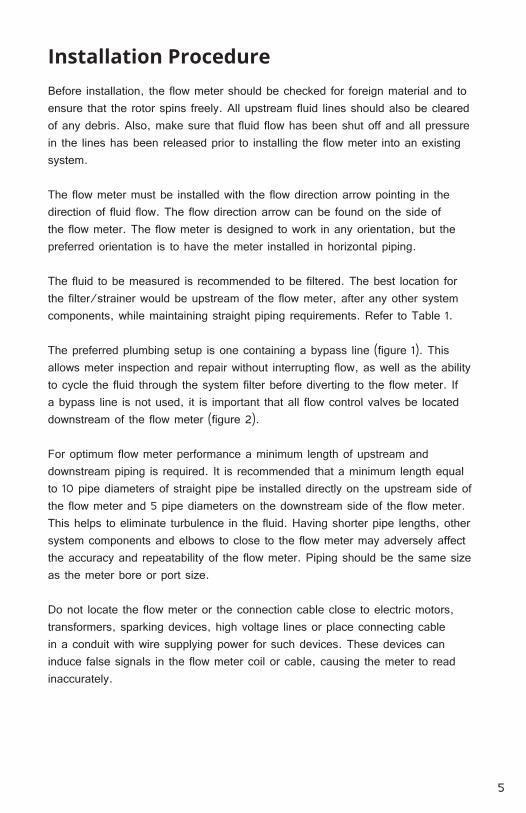
The preferred plumbing setup is one containing a bypass line (figure 1). This allows meter inspection and repair without interrupting flow, as well as the ability to cycle the fluid through the system filter before diverting to the flow meter. If a bypass line is not used, it is important that all flow control valves be located downstream of the flow meter (figure 2).
For optimum flow meter performance a minimum length of upstream and downstream piping is required. It is recommended that a minimum length equal to 10 pipe diameters of straight pipe be installed directly on the upstream side of the flow meter and 5 pipe diameters on the downstream side of the flow meter. This helps to eliminate turbulence in the fluid. Having shorter pipe lengths, other system components and elbows to close to the flow meter may adversely affect the accuracy and repeatability of the flow meter. Piping should be the same size as the meter bore or port size.
Do not locate the flow meter or the connection cable close to electric motors, transformers, sparking devices, high voltage lines or place connecting cable in a conduit with wire supplying power for such devices. These devices can induce false signals in the flow meter coil or cable, causing the meter to read inaccurately.

6
Start-Up Procedure
The following procedures should be observed when installing the flow meter and running it for the first time after installation.
1. After meter installation, close the isolation valves and open the bypass valve. Flow liquid through the system for a sufficient time to eliminate any air or gas in the flow line.
WARNING: Air and gas, running at a high velocity, can damage the internal components of the flow meter.
2. Slowly open the upstream isolating valve to fill the flow meter with liquid.3. Open the downstream isolating valve to start fluid flow through the flow
meter, permitting the flow meter to start to operate, then close the bypass valve completely.
4. If the downstream valve is used as a flow control valve, adjust the valve to provide the required flow rate through the flow meter.
WARNING: Never hit a flow meter, empty of fluid, with full fluid flow. This fluid shock or hammering effect on the internals of the flow meter can permanently damage the internal components.
If any problems with the flow meter arise, consult the Trouble Shooting Guide (Appendix A). If you cannot resolve the problems using this guide, please consult the factor for assistance.
Repair Kits and Flow Meter Maintenance
Repair kits are available if needed, see the Maintenance Guide for part numbers. The Maintenance Guide also includes important information on how to remove, clean, inspect and reinstall the repair kits into the flow meter.

7
Figure 2
Figure 1

8
Problem/Issue Possible Cause Possible FixThe flow meter is
indicating a flow
rate which is higher
than the actual flow
rate.
1. Meter cavitation.
2. Buildup of particles/debris on the rotor
support.
3. Air or gas in the fluid.
4. Upstream piping at inlet of flow meter
is smaller than recommended.
1. Increase back pressure to the flow
meter.
2. Clean rotor support & check filter
3. Purge air/gas from system or add
a gas eliminator upstream of flow
meter.
4. Change piping to recommended
size.
The flow meter is
indicating a flow
rate which is lower
than the actual flow
rate.
1. Buildup of particles/debris on the rotor.
2. Excessive wear on support bushing.
3. Fluid viscosity higher than calibration
fluid viscosity.
4. Fluid flow is leaking through to bypass
piping section.
1. Clean rotor & meter & check filter
2. Replace rotor.
3. Recalibrate flow meter with systems
fluid or a similar viscosity fluid
4. Check bypass valves are closed.
Replace if necessary.
Erratic system
indication from
remote monitor.
Flow meter itself
seems to work fine.
1. Ground loop in shielding. 1. Ground shield one place only.
2. Look for internal electronic
instrument ground.
3. Isolate cables from electrical noise.
Appendix A

9
Flow meter is
indicating fluid flow
when system is shut
off.
1. Mechanical system vibration.
2. Fluid leak somewhere in the
system.
3. Electrical RF/EMI noise.
1. Try to isolate the flow meter from the
source of vibration
2. Repair or replace leaking component
or piping.
3. Improve grounding of signal cable.
4. Locate & remove noise source.
Flow meter is
indicating no flow
when fluid is known to
be flowing.
1. Damaged internal components
due to fluid shock on initial
startup.
2. Excessive buildup of particles/
debris on shaft and/or support
bushing.
3. Actual fluid flow rate is below the
stated range of the meter.
4. Faulty sensor/pickup, wiring or
monitor.
1. Rebuild the flow meter with a new
repair kit.
2. Clean the flow meter & check the filter.
3. Increase flow rate to be within the flow
meters stated range.
4. Verify sensor is seated all the way
down.
5. Replace pickup or have it repaired by
factory
6. Verify unit is properly wired
7. Replace monitor or have it repaired by
factory.
Indicated flow rate
at lower flow rates
is erratic, but fine at
higher flow rates.
1. Actual fluid flow rate is below the
stated range of the meter.
2. Buildup of particles/debris on
internal components.
1. Increase flow rate to be within the flow
meters stated range
2. Clean the flow meters internal
components & check the filter.
Problem/Issue Possible Cause Possible Fix
Appendix A

10

11

COMPANY
262.884.9800 | www.aw-lake.com 2440 W. Corporate Preserve Dr. Suite #600, Oak Creek, WI 53154
©2016 AW-Lake Company. All rights reserved. Doc ID:TURBINEMAN16