Embed Size (px)
Citation preview

Nanoscale Advances
rsc.li/nanoscale-advances
ISSN 2516-0230
Volume 3Number 117 June 2021Pages 2963–3318
PAPERKnut Deppert et al.Continuous gas-phase synthesis of core–shell nanoparticles via surface segregation

NanoscaleAdvances
PAPER
Ope
n A
cces
s A
rtic
le. P
ublis
hed
on 1
4 A
pril
2021
. Dow
nloa
ded
on 1
2/13
/202
1 7:
59:5
1 PM
. T
his
artic
le is
lice
nsed
und
er a
Cre
ativ
e C
omm
ons
Attr
ibut
ion
3.0
Unp
orte
d L
icen
ce.
View Article OnlineView Journal | View Issue
Continuous gas-
aLund University, Department of Physics
Sweden. E-mail: [email protected] University, Department of Chemistry
Synthesis, Box 124, 22100 Lund, Sweden
† Electronic supplementary informa10.1039/d0na01061h
‡ Contributed equally to this work.
Cite this:Nanoscale Adv., 2021, 3, 3041
Received 18th December 2020Accepted 14th April 2021
DOI: 10.1039/d0na01061h
rsc.li/nanoscale-advances
© 2021 The Author(s). Published by
phase synthesis of core–shellnanoparticles via surface segregation†
Markus Snellman, ‡a Namsoon Eom, ‡a Martin Ek, b Maria E. Messing a
and Knut Deppert *a
Synthesis methods of highly functional core@shell nanoparticles with high throughput and high purity are in
great demand for applications, including catalysis and optoelectronics. Traditionally chemical synthesis has
been widely explored, but recently, gas-phase methods have attracted attention since such methods can
provide a more flexible choice of materials and altogether avoid solvents. Here, we demonstrate that
Cu@Ag core–shell nanoparticles with well-controlled size and compositional variance can be generated
via surface segregation using spark ablation with an additional heating step, which is a continuous gas-
phase process. The characterization of the nanoparticles reveals that the Cu–Ag agglomerates
generated by spark ablation adopt core–shell or quasi-Janus structures depending on the compaction
temperature used to transform the agglomerates into spherical particles. Molecular dynamics (MD)
simulations verify that the structural evolution is caused by heat-induced surface segregation. With the
incorporated heat treatment that acts as an annealing and equilibrium cooling step after the initial
nucleation and growth processes in the spark ablation, the presented method is suitable for creating
nanoparticles with both uniform size and composition and uniform bimetallic configuration. We confirm
the compositional uniformity between particles by analyzing compositional variance of individual
particles rather than presenting an ensemble-average of many particles. This gas-phase synthesis
method can be employed for generating other bi- or multi-metallic nanoparticles with the predicted
configuration of the structure from the surface energy and atomic size of the elements.
1. Introduction
Recently, a signicant amount of research effort has beendevoted to the production of core–shell nanoparticles, whichare composed of an inner core material coated by a shell ofa different material. Such attention to core–shell nanoparticlesarises from the fact that they can exhibit enhanced physicaland/or chemical properties.1–3 Furthermore, core–shell particleswith distinctly new properties compared to those of theconstituent materials can be designed by tuning, for example,their size, shell thickness, and structures.4–7 A large number ofresearch projects are underway to fabricate highly functionalcore–shell materials for applications in various elds, includingoptoelectronic devices,8,9 biomedical imaging,10,11 catalysis,12,13
and plasmonics.14,15
Currently, chemical synthesis techniques such as sol–gel,16,17
solvothermal,18 seed-mediated growth,19 and cation exchange20
and NanoLund, Box 118, 22100 Lund,
and NanoLund, Centre for Analysis and
tion (ESI) available. See DOI:
the Royal Society of Chemistry
are the most popular methods for fabricating core–shell nano-particles. However, interface and surface contaminations areoen an unavoidable issue in the multiple-step, solution-basedapproaches. These impurities inevitably make solution-basedprocesses time consuming as many steps are required toremove contaminants. The process of removing ligands alsointroduces uncertainty regarding the nal size and structure ofthe nanoparticles.21,22 Contrary to the widely popular chemicalsynthesis, signicantly less attention has been paid to solvent-freegas-phase synthesis methods, which offer high purity and highthroughput in nanoparticle production. Recently, gas-phasesynthesis techniques based on low-pressure multi-magnetrongas aggregation sources – where one target acts as the source ofthe core material and the others as one or more sources coatingmaterials – have enabled the fabrication of core–shell particleswith tunable sizes and shapes.23,24 Apart from the demanding highvacuum requirements,25 these methods oen suffer from nucle-ation of pure-element byproducts,24–26 and achieving uniformity inbimetallic morphology is challenging as the nanoparticlesgenerated by non-equilibrium, fast kinetics processes that do notinclude an additional annealing process oen include randomand unpredictable metastable phases.27,28 Having control oversize, composition, and morphology is desirable, as it enablesinvestigations of the nanoparticle properties' effects on various
Nanoscale Adv., 2021, 3, 3041–3052 | 3041

Nanoscale Advances Paper
Ope
n A
cces
s A
rtic
le. P
ublis
hed
on 1
4 A
pril
2021
. Dow
nloa
ded
on 1
2/13
/202
1 7:
59:5
1 PM
. T
his
artic
le is
lice
nsed
und
er a
Cre
ativ
e C
omm
ons
Attr
ibut
ion
3.0
Unp
orte
d L
icen
ce.
View Article Online
applications. We note that in this article we use the term ‘meta-stable’ for any nanoparticle congurations that are not in thethermodynamically stable global energy minimum.
Here, we present a continuous gas-phase process based on sparkablation29 with the capability of creating uniformly structured core–shell bimetallic nanoparticles with precisely controlled size andcomposition not containing other random metastable congura-tions. Spark ablation is a gas-phase synthesis technique with anappealingly simple design that utilizes a high voltage sparkdischarge between two electrodes acting as the material source forthe synthesized nanoparticles. It has been used to create varioustypes of materials such as semiconducting nanoparticles30 andcomposite metal nanoparticles.31 Similar to a related techniqueknown as arc discharge,32–35 it is an environmentally-friendly, inex-pensive alternative to chemical synthesis techniques and offersa continuous production route at atmospheric pressure. The tech-nique can readily be upscaled tomass-production by placing severalelectrode pairs in parallel. Recently, spark ablation has been used toproduce Ag@Au and Au@Ag core–shell nanoparticles viaa condensation mechanism which requires modication of theconventional spark ablation for a separate coating step.36
In this study, we exploit the surface segregation phenomenon ingenerating core–shell bimetallic nanoparticles using spark ablationin a continuous process without an additional coating step. Thesurface segregation phenomenon refers to the enrichment of onecomponent of a mixture in the surface region. It is generally agreedthat surface segregation depends on an interplay between theatomic radii, cohesive energy, surface energy, and electronegativityof the core and shell materials.37 As a rule of thumb, one expectsthat themetals with smaller atomic radii and larger surface energieswould tend to occupy the core region. Utilizing the surface segre-gation mechanism, one can produce core–shell nanostructures bysimply evaporating both core and shell materials simultaneously inthe gas phase, rendering the process ‘continuous’ without the needof a separate coating process.38–42 Note that in situ heat treatment ingas phase synthesis methods has been reported to be efficient forphase transformation.43 In our setup, heat-induced surface segre-gation occurs when the agglomerates of bimetallic nanoparticles,synthesized by spark ablation, pass through a tube furnace duringwhich the agglomerates become spherical core–shell structures.
In generating bimetallic core–shell nanoparticles usingspark ablation via surface segregation, we have chosen Cu–Ag asour model system as the atomic radius mismatch is relativelyhigh, and the surface energy difference is sufficient (1210 mJm�2 for Ag and 2130 mJ m�2 for Cu).44 Additionally, Cu–Ag isa well-studied immiscible material system. We have investi-gated the morphology, composition, and inter-particle hetero-geneity of the generated Cu@Ag core–shell nanoparticles byscanning transmission electron microscopy (STEM), andenergy-dispersive X-ray spectroscopy (EDX). To provide more in-depth insight into the structural evolution of Cu–Ag nano-particles during the heating and cooling processes, we alsoconducted molecular dynamics (MD) simulations. The numer-ical modeling corroborates our experimental results that thecompaction temperature inuences the nanoparticle's nalstructure and that the core–shell formation is attributed to theheat-induced surface segregation.
3042 | Nanoscale Adv., 2021, 3, 3041–3052
In addition to the capability of generating uniform core–shell nanoparticles with well-controlled size and composition,exploiting the surface segregation together with the sparkablation method is further benecial. As the core@shell nano-particles generated via the presented synthesis method havealready undergone a heating cycle, they are expected to exhibithigh structural stabilities at elevated temperatures, which issupported by the MD simulations. It is well-known that nano-particles with equilibrium shape and narrow-sized distributionsare favorable for suppressing sintering.45 The suppression ofsintering makes the method appealing for catalysis applica-tions, where the structural stability of bimetallic nanoparticlesin elevated temperatures is essential.
The gas-phase synthesis method presented here can beemployed for other bi- or multi-metallic systems with sufficientdifferences in surface energy and atomic radius of the elementsfor generating core–shell nanoparticles. However, this methodis not just limited to the production of core–shell nanoparticles.The same method can also be used to create other structures(e.g., quasi-Janus or alloy) with the only requirement to designthe desired structures being the knowledge of the surfaceenergy and atomic size of the constituent elements.
2. Experimental2.1. Nanoparticle generation
First, the spark ablation system (Fig. S1†), where spark ablationtakes place, was evacuated with a rotary pump. Aer reachinga pressure of lower than 1 mBar, N2 : H2 carrier gas (95% : 5%;purity 99.9999%; Linde) was let in at a ow rate of 1.68 L min�1,regulated with mass ow controllers (Bronkhorst, El-Flow-Select) and the pressure was kept at 1015 mBar with a pres-sure controller (Bronkhorst, El-Press-Select). A high-voltage,high power supply (Technix, Model CCR15-P-750) was used tocharge a 20 nF capacitor bank shunted to the metallic elec-trodes enclosed in a chamber ushed with the carrier gas. Theelectrodes are separated by an air gap of about 2 mm. Agrounded pure Cu electrode (GoodFellow, >99.99%) anda biased pure Ag electrode (GoodFellow, >99.95%) were used inthis work. At a specic voltage over the capacitors and electrodegap, the carrier gas in the electrode gap breaks down intoa conducting plasma, carrying an oscillating current from thedischarging capacitor bank that ablates material from theelectrodes' surfaces. The ablated material vapors nucleate intosmall (<10 nm) singlet nanoparticles that grow by full coales-cence from collisions until they reach a diameter where furthercollisions between the primary particles lead to the formation offractal-like agglomerates by coagulation and partial sintering.46
Aer a few ms, the electrode gap regains its resistive properties,and the charge cycle is repeated. The breakdown voltage wasmonitored and set to 3.0–4.0 kV implicitly by the electrode gap.
2.2. Nanoparticle compaction and size selection
Aer generation, the Cu–Ag agglomerates were carried by thecarrier gas downstream in the setup for subsequent thermaltreatment (compaction) and size selection. First, the particles
© 2021 The Author(s). Published by the Royal Society of Chemistry

Paper Nanoscale Advances
Ope
n A
cces
s A
rtic
le. P
ublis
hed
on 1
4 A
pril
2021
. Dow
nloa
ded
on 1
2/13
/202
1 7:
59:5
1 PM
. T
his
artic
le is
lice
nsed
und
er a
Cre
ativ
e C
omm
ons
Attr
ibut
ion
3.0
Unp
orte
d L
icen
ce.
View Article Online
were assigned a known charge distribution in a b emitting 63Nineutralizer. This enables subsequent size selection via electricalmobility using a tandem differential mobility analyzer (DMA)setup,47 consisting of two DMAs (DMA1: TSI 3081 Long; DMA2:custom Vienna type48) with 10 L min�1 sheath ows. Inside theDMAs, an electric eld classies particles of particular electricalmobility (mobility in an electric eld), a function of diameterand charge. The agglomerates were compacted to sphericalparticles in a tube furnace (Lenton LTF) positioned betweenDMA1 and DMA2. Aer size selection in DMA2, the particleswere either counted with an electrometer (TSI 3086B) ordeposited with an electric eld in a custom electrostaticprecipitator (ESP).49–51 The electrical mobility range of selectedparticles is proportional to Qa/Qsh where is Qa is the carrier gasow rate (1.68 L min�1) and Qsh is the DMA sheath ow rate (10L min�1), equivalent to a ow ratio of ca. 1/6 and a size distri-bution width of the size selected aerosol nanoparticles witha diameter Dp of �1/6 Dp.52 Using the tandem DMA setup, evennarrower size distributions can be obtained, as shown inFig. S2† where compacted CuAg aerosol nanoparticles weredeposited with an electrical mobility diameter of 30 nm andmeasured from SEM micrographs.
2.3. Particle characterization
Electron microscopy and elemental analysis were used to charac-terize Cu@Ag nanoparticles offline. Only DMA2 was used (DMA1was bypassed) to ensure a shorter deposition time at the cost ofa broader particle size distribution. Particles size selected withDMA2 at electrical mobility diameter of 30 nm were deposited inthe ESP set to 6–10 kV on holey carbon lm coated Au TEM grids(Agar Scientic). The ESP chamber was purged in N2 (purity99.999%) before and aer deposition. Depositing 30 nm particlesensured a sufficient stability necessary for acquiring STEM-EDXmaps with enough counts for detailed analysis. The samples werehandled in air before STEM imaging (JEOL 3000F operated at 300kV). In STEM mode, the particles were imaged with a high-angleannular dark-eld (HAADF) detector. Elemental distribution maps(EDX maps) were also obtained in STEM mode with the coupledEDX spectrometer (Oxford Instruments), and the data was analyzedand processed in the INCA soware (Oxford Instruments) and withthe Hyperspy package53 in Python to extract the composition of Ag-rich andCu-rich phases. Additional TEM-EDX statistics on 30 singleCu–Ag nanoparticles per furnace temperature at temperatures of750 �C, 850 �C and 950 �C were acquired in a 300 kV Hitachi TEM,with similar EDX spectrometer, and the data was analyzed with theassociated Aztec soware (Oxford Instruments).
2.4. Molecular dynamics simulations
Embedded-atom method (EAM)54 potentials for the Cu–Agsystem developed by Williams et al.55 were employed in themolecular dynamics simulations. Spherical Cu and Ag nano-particles were constructed from their perfect face-centeredcubic (FCC) crystals with particle diameters ranging from 2.5to 4.2 nm. The unsupported Cu and Ag nanoparticles wereequilibrated separately at 27 �C for 100 ps and were subse-quently placed next to each other in a nonperiodic vacuum cell.
© 2021 The Author(s). Published by the Royal Society of Chemistry
This initial relaxation process leads to a Cu–Ag aggregate that isa small representation of metastable aggregate created from thefast quenching process in spark ablation. The equations ofmotion were integrated by the velocity-Verlet algorithm56 witha time step of 1 fs. To simulate the compaction process in thefurnace, the aggregate of Cu and Ag were continuously heatedup to 750 �C, 850 �C, and 950 �C at a heating rate of 0.13 �C ps�1.The system was then cooled at a cooling rate of 0.13 �C ps�1 andequilibrated for 100 ps once the temperature reached 27 �C.Note that a combination of MD and Monte Carlo (force-biasmethod) simulations was employed for the nanoparticle com-pacted at 850 �C as its structure did not reach a crystalline statein the MD simulation. The canonical ensemble (i.e., NVT) wasemployed with Nose–Hoover thermostat for temperaturecontrol. Additional simulations for larger particles (6 nm and10 nm in diameter) were carried out under the same simulationsetup. All the simulations were performed using the LAMMPS57
code, and PyMOL58 and OVITO59 were used for visualizations.Crystallinity of the simulated nanoparticles were analyzed usingpolyhedral template matching.59,60
3. Results and discussion3.1 Compaction behavior of the Cu–Ag nanoparticles
The particles generated in the spark-discharge chamber arefractal-like agglomerates consisting of primary particles in thesize of 2–10 nm. It has been reported that Cu–Ag nanoparticlesgenerated from spark ablation of sintered Cu–Ag electrodesshow an increase in Cu–Ag solubility on the nanoscale despitetheir intrinsic immiscibility.61 Similarly, it has been shown thatprimary particles generated from two different immisciblemetal electrodes can form mixed crystalline phases givena sufficiently fast quenching.62 Thus, although it is challengingto correctly characterize the composition and morphology ofprimary particles due to their small size, we believe that there isa high likelihood that the primary particles in the Cu–Agnanoparticle agglomerates created in the spark ablation arebinary mixtures of Cu and Ag. And, as the agglomeratesapproach the tube furnace, segregation is expected to take placedue to increased atomic diffusion in the heating process. Wediscuss this further in the later section.
The Cu–Ag particle agglomerates become compacted tospherical particles as they pass through the tube furnace. Bykeeping DMA1 at a xed electric mobility diameter of 35 nm andscanning the electric mobility diameter of DMA2, the compac-tion behavior of the Cu@Ag nanoparticles was obtained ina tube furnace temperature range from room temperature to1000 �C (Fig. 1). Each data point in Fig. 1 corresponds to theelectric mobility diameter associated with the maximumparticle concentration for that temperature.
When the furnace was set to room temperature, the mobilitydiameter of the nanoparticles scanned by DMA2 coincides withthat of DMA1. This implies that there is no morphologicalchange in the nanoparticles at that temperature. As the furnacetemperature increases, however, the mobility diameterdecreases with more noticeable changes at 400–600 �C. At thistemperature range, the structural evolution from a clustered,
Nanoscale Adv., 2021, 3, 3041–3052 | 3043
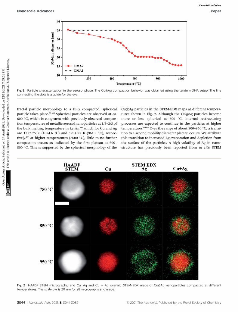
Fig. 1 Particle characterization in the aerosol phase. The Cu@Ag compaction behavior was obtained using the tandem DMA setup. The lineconnecting the dots is a guide for the eye.
Nanoscale Advances Paper
Ope
n A
cces
s A
rtic
le. P
ublis
hed
on 1
4 A
pril
2021
. Dow
nloa
ded
on 1
2/13
/202
1 7:
59:5
1 PM
. T
his
artic
le is
lice
nsed
und
er a
Cre
ativ
e C
omm
ons
Attr
ibut
ion
3.0
Unp
orte
d L
icen
ce.
View Article Online
fractal particle morphology to a fully compacted, sphericalparticle takes place.63–65 Spherical particles are observed at ca.600 �C, which is congruent with previously observed compac-tion temperatures of metallic aerosol nanoparticles at 1/3–2/3 ofthe bulk melting temperature in kelvin,66 which for Cu and Agare 1357.75 K (1084.6 �C) and 1234.95 K (961.8 �C), respec-tively.67 At higher temperatures (>600 �C), little to no furthercompaction occurs as indicated by the rst plateau at 600–800 �C. This is supported by the spherical morphology of the
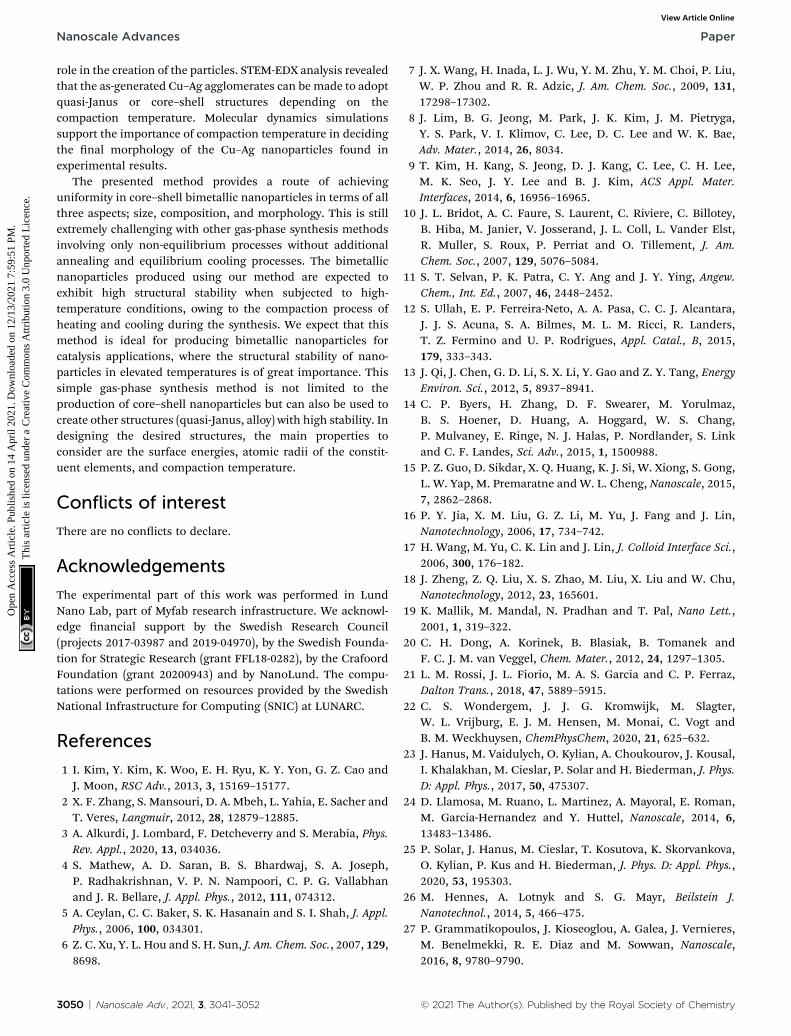
Fig. 2 HAADF STEM micrographs, and Cu, Ag and Cu + Ag overlaidtemperatures. The scale bar is 20 nm for all micrographs and maps.
3044 | Nanoscale Adv., 2021, 3, 3041–3052
Cu@Ag particles in the STEM-EDX maps at different tempera-tures shown in Fig. 2. Although the Cu@Ag particles becomemore or less spherical at 600 �C, internal restructuringprocesses are expected to continue in the particles at highertemperatures.66,68 Over the range of about 900–950 �C, a transi-tion to a second mobility diameter plateau occurs. We attributethis transition to increased Ag evaporation and depletion fromthe surface of the particles. A high volatility of Ag in nano-structure has previously been reported from in situ STEM
STEM-EDX maps of Cu@Ag nanoparticles compacted at different
© 2021 The Author(s). Published by the Royal Society of Chemistry

Paper Nanoscale Advances
Ope
n A
cces
s A
rtic
le. P
ublis
hed
on 1
4 A
pril
2021
. Dow
nloa
ded
on 1
2/13
/202
1 7:
59:5
1 PM
. T
his
artic
le is
lice
nsed
und
er a
Cre
ativ
e C
omm
ons
Attr
ibut
ion
3.0
Unp
orte
d L
icen
ce.
View Article Online
studies by Lu et al.69 Additionally, the Ag depletion is corrobo-rated qualitatively by evaporation rates predicted by the Knud-sen equation (SE1), as plotted in Fig. S3 in ESI.† Above 1000 �C,we expect the material evaporation rate of both Ag and Cu toincrease further and hence a continued reduction in the electricmobility diameter in Fig. 1. The consequent Cu enrichment willbe discussed further in connection to the compositional anal-ysis in the following section.
3.2 Morphology and composition of the Cu–Agnanoparticles
STEM-EDX maps of single nanoparticles compacted at threedifferent temperatures (750 �C, 850 �C and 950 �C) were ob-tained to determine the Cu and Ag distribution and are shownin Fig. 2. We observe two distinct morphological phases ofCu@Ag nanoparticles in the STEM-EDX maps. When com-pacted at 750 �C, the particles adopt a quasi-Janus structure.However, at 850 �C, the EDX maps clearly indicate a core@shellmorphology. In all the STEM-EDXmaps in Fig. 2, it appears thatAg is present in Cu rich parts and vice versa. Using non-negativematrix factorization (NMF) with the Python library Hyperspy,53
we were able to separate the EDX maps into Cu rich and Ag richcomponents for particles synthesized at 750 �C, 850 �C and950 �C for detailed quantication of the Cu rich and Ag richsegments (Fig. S4–S6†). The atomic composition in the Cu richand Ag rich parts of particles synthesized at 750 �C (quasi-Janusparticles), 850 �C and 950 �C (core@shell particles) are shown inTable 1. Moreover, the NMF spectral components in Fig. S4–S6†reveal little to no oxygen in the Cu rich cores, while a smalloxygen signal was detected in the Ag rich shell for the particlescompacted at 850 �C and 950 �C (Fig. S5 and S6†). This signiesa resistance to oxidation, possibly due to high surface content ofAg. Although the samples were handled in air prior to STEM-EDX, the addition of 5% H2 to the carrier gas has been shownto be benecial for reducing oxidation of particles synthesizedby SDG.70 We detected clear signs of oxidation only aer severalweeks of ambient storage.
Additionally, the average compositions, as determined byTEM-EDX of 30 particles per temperature at the same threetemperatures (750 �C, 850 �C and 950 �C), are given in Fig. 3. Itshows that the Cu–Ag particle composition range is narrow atall three temperatures, with a standard deviation of 5–7 at%.Clearly, the particles become enriched with Cu at 950 �C, whichcorrelates well with the decrease in mobility diameter observedin the compaction study above 900 �C (Fig. 1), that was attrib-uted to Ag evaporation. Typically, the composition of gas phasesynthesized nanoparticles is investigated by interrogating
Table 1 STEM-EDX composition of Cu rich and Ag rich parts of Cu@Ag nparticles (950 �C)
750 �C 850
Cu-rich phase Ag-rich phase Cu
Cu (at%) 97.9 � 3.0 11.7 � 2.2 89.Ag (at%) 2.1 � 3.0 88.3 � 2.2 10.
© 2021 The Author(s). Published by the Royal Society of Chemistry
a large number of particles simultaneously.25,26,71,72 Thisapproach provides a good sample of ensemble-averaged prop-erties of many particles, but cannot provide information oncompositional variance between particles. Indeed, to the best ofour knowledge, the compositional uniformity between indi-vidual bimetallic nanoparticles synthesized from coagulatingand/or coalescing monometallic particles in the gas-phase isnot well-documented. Krishnan et al.73 reported a very low inter-particle compositional variance on single nanoparticlessynthesized by a sectional Mo–Cu sputtering target, but did notaccount for the number of particles interrogated by EDX. This isto the best of our knowledge the rst time that compositionalvariance of individual particles synthesized by sintering ofagglomerates formed by coagulation of bimetallic species hasbeen studied, and is of relevance for multiple gas phase basedtechniques for synthesis of bimetallic nanoparticles fromcoagulating and coalescing particles. A quasi-Janus or crescentmorphology observed at a compaction temperature of 750 �Chas been previously reported for this material system74–76
although not for Cu@Ag particles synthesized in the gas phaseto the best of our knowledge. Langlois et al.75 studied theannealing of Cu@Ag core–shell nanoparticles on a substrateand observed that the structure transformed to Janus-like quasi-Janus when the amount of Ag in a particle is large. They re-ported a quasi-Janus conguration adopted beyond a critical Agshell thickness of 3–4 nm. A global optimization study on small(100 to 300 atoms) Cu–Ag particles of varying compositionsupported on MgO(001) also showed the preference of Ag tomigrate to the surface, with quasi-Janus morphologies appear-ing at higher Ag concentrations.77 Comparing with our results inFig. 2 and 3, a simple geometrical derivation for a sphericalcore–shell particle of uniform core and shell compositions (eqn(E6) in ESI†) suggests an Ag shell thickness of ca. 4.9 nm, 4.8 nmand 1.8 nm for the particles compacted at 750 �C, 850 �C and950 �C, respectively. In our study, we do not nd a clear relationbetween the element quantity and particle morphology, andhence the observation made by Langlois et al. is not supportedby our experiments. The particles studied by that group75 were,however, synthesized in a fundamentally different way viaevaporation and thermal dewetting, where the substrate mayplay a signicant role in the formation and the thermodynam-ical stability of the particles. In our study, where Cu–Agagglomerates compact directly in the gas phase, we determinethe compaction temperature to be the most crucial variable indeciding the morphology of Cu@Ag core–shell nanoparticles.
Numerous theoretical works have been reported on thephase stability of Janus, core–shell, and alloyed Cu–Ag
anoparticles determined from four particles (750 �C, 850 �C) and three
�C 950 �C
core Ag shell Cu core Ag shell
4 � 3.5 11.8 � 1.5 99.9 � 0.1 28.0 � 8.16 � 3.5 88.2 � 1.5 0.1 � 0.1 72.0 � 8.1
Nanoscale Adv., 2021, 3, 3041–3052 | 3045

Fig. 3 Ag composition distribution for Cu–Ag particles as determined by TEM-EDX for 30 individual particles at each temperature.
Nanoscale Advances Paper
Ope
n A
cces
s A
rtic
le. P
ublis
hed
on 1
4 A
pril
2021
. Dow
nloa
ded
on 1
2/13
/202
1 7:
59:5
1 PM
. T
his
artic
le is
lice
nsed
und
er a
Cre
ativ
e C
omm
ons
Attr
ibut
ion
3.0
Unp
orte
d L
icen
ce.
View Article Online
nanoparticles with differing conclusions. A model based onclassical thermodynamics predicts the Janus morphology fornanoparticles with small Cu core size and large Ag quantity.78
The same model, however, also predicts the preference of analloyed composition over the core–shell morphology for parti-cles with size and composition similar to those synthesizedhere, which we do not observe. Another thermodynamicalmodel based on surface energy differences of Ag and Cu,76
where the authors synthesized crescent (quasi-Janus) andCu@Ag core–shell nanoparticles by a solution process, suggeststhat a quasi-Janus morphology is always preferred but that theenergetic difference between the two morphologies decreaseswith increasing Ag content, making the core@shell morphologymore likely for particles with a high Ag fraction. This proposedtrend is not reected in our results as particles synthesized at750 �C and 850 �C have a similar composition yet a differentmorphology, i.e., the particles compacted at 750 �C adopta quasi-Janus structure, while the particles compacted at 850 �Cadopt a core@shell morphology. Additionally, the particlescompacted 950 �C also adopt a core@shell morphology withsignicantly less Ag content (<25 at%). We note that the modelproposed by Osowiecki et al.76 should be accompanied bymodeling of the signicant strain energy present in the Cu–Aginterface, due to the lattice mismatch of 13%,78,79 such as thecontinuum-mechanics model implemented for CdTe@CdSe80
and CdSe@CdS81 colloidal core@shell nanoparticles. Themodel in ref. 76 is further complicated by the surface energydependence on particle diameter. While several models predicta decrease of surface energy with decreasing nanoparticleradius, as compared to bulk values,82,83 experimental data onnanoparticles suspended in the gas-phase show oppositetendency.84,85 Hence, it is clear that a suitable model forsynthesis of core–shell structures via equilibrium gas-phaseprocesses is lacking, which we address in the next section.
3.3 Molecular dynamics simulations
We performed molecular dynamics simulations to obtainfurther insight into the structural evolution of Cu–Ag nano-particles during the heating and cooling processes. We carriedout simulations based on well-established MD-routines for the
3046 | Nanoscale Adv., 2021, 3, 3041–3052
Cu–Ag nanoparticle system,27,86–88 to demonstrate how quasi-Janus and core–shell structures can form from an aggregateby adjusting only compaction temperature. We mimic theexperimental conditions by including both heating and coolingprocess that corresponds to entering and exiting the tubefurnace.
First, we present the simulation results and analysis of smallparticles (�4 nm in diameter). In order to employ the MDresults in explaining the experimental results on signicantlylarger particles, later in the section, we discuss the simulationresults on larger particles (6 nm and 10 nm in diameter).
The TEM-EDX analysis shows that the atomic percentage ofthe Cu–Ag nanoparticles compacted at 750 �C was Cu : Ag ¼39 : 61 (see Fig. 3). For this atomic ratio, the compactionbetween a Cu nanoparticle with a diameter of 3.0 nm and an Agnanoparticle with a diameter of 3.9 nm was simulated.
The structural evolution of a Cu–Ag nanoparticle at thistemperature is shown in Fig. 4a and b, along with the evolutionof crystallinity (Fig. 4c) and the change in the average potentialenergy per atom (Fig. 4d). As the particles are heated from 27 �Cto 750 �C, surface atoms of Ag start diffusing to the surface of Cuas expected from the lower surface energy and cohesive energyof Ag. It was observed that the Ag atoms do not readily diffuseinto the Cu core region. At 750 �C, the system forms a quasi-Janus structure with Ag atoms on the surface of Cu. As thetemperature decreases, the Janus structure remains unchangedexcept for the continued diffusion of Ag atoms on the Cusurface. When the system is cooled back to a temperature of27 �C, an overall crystalline quasi-Janus Cu–Ag nanoparticleforms. A few Cu atoms diffuse to the Ag side. This overall quasi-Janus morphology in the MD simulation agrees with the STEMEDX maps (Fig. 2) of the Cu–Ag nanoparticles compacted at thesame temperature. It is further supported by the quanticationof the NMF of the same EDX maps (Table 1), where the Cu-richphase contains little Ag and some Cu have incorporated in theAg-rich phase. While an increased solubility of Cu in Ag hasbeen observed previously upon quenching Cu–Ag mixed nano-particles in inert gas condensation,89 this is, to the best of ourknowledge, the rst time it has been observed in a compara-tively slower cooling cycle.
© 2021 The Author(s). Published by the Royal Society of Chemistry

Fig. 4 (a) Structural evolution of Cu(red)–Ag(green) nanoparticles when heated from 27 �C to 750 �C and cooled back down to 27 �C. Here, theatomic ratio of the Cu–Ag is Cu : Ag¼ 39 : 61. (b) Cross-sectional view of the simulated nanoparticles. (c) Cross-sectional view of the crystallinityof the simulated nanoparticles during the heating and cooling. (d) Potential energy per atom of Cu (3.0 nm), Ag (3.9 nm), and Cu–Ag nano-particles during the heating process.
Paper Nanoscale Advances
Ope
n A
cces
s A
rtic
le. P
ublis
hed
on 1
4 A
pril
2021
. Dow
nloa
ded
on 1
2/13
/202
1 7:
59:5
1 PM
. T
his
artic
le is
lice
nsed
und
er a
Cre
ativ
e C
omm
ons
Attr
ibut
ion
3.0
Unp
orte
d L
icen
ce.
View Article Online
To determine the melting point of the simulated Cu–Ag nano-particles, the average potential energy per atom as a function of thetemperature is plotted (Fig. 4d). Additionally, MD simulations forsingle-particles are conducted on a single Cu and a single Agparticle to obtain references for the melting behavior of Cu–Agbimetallic particles (Fig. 4d). The melting point is generally denedto be the temperature at which the potential energy increasesabruptly due to the absorption of latent heat of fusion.90,91 It is wellknown that the melting point of nanoparticles is size-dependent,that is, it decreases as the size of nanoparticle decreases.92 Fig. 4dshows the change in potential energy of a 3.0 nm single Cu, and ofa 3.9 nm single Ag nanoparticle. The average potential energy peratom increases linearly with increasing temperature. In Fig. 4d, thepotential energy per atom of both Cu and Ag do not show anyabrupt jumps. This implies that at 750 �C, neither Cu nor Ag melts.Crystallinity analysis59,60 of the MD results also indicates that eachnanocluster remains crystalline during the heating and cooling asshown in Fig. 4c. It is clearly seen that at 750 �C, the crystallinity ofboth Cu and Ag remain FCC during the coalescence. Thus, itsupports an assumption that the quasi-Janus structure is created bysurface diffusion.
For the Cu–Ag nanoparticles compacted at 850 �C with anatomic ratio of Cu : Ag ¼ 39 : 61 (see Fig. 3), a Cu nanoparticlewith a diameter of 3.0 nm and an Ag nanoparticle witha diameter of 3.9 nm were simulated and are shown in Fig. 5a–d. At 850 �C, both the single Ag and the single Cu nanoparticlemelt as indicated by the abrupt jump in the average potentialenergy per atom (Fig. 5d) and a similar jump in the potentialenergy is also observed for a Cu–Ag nanoparticle. Melting of thenanoparticle at 850 �C was further supported by crystallinityanalysis. As shown in Fig. 5c, the initial FCC structures are nolonger observed and become amorphous at 850 �C. As thetemperature decreases at a cooling rate of 0.13 �C ps�1 the Cu–
© 2021 The Author(s). Published by the Royal Society of Chemistry
Ag nanoparticle transforms to an internally mixed nanoparticlewith an Ag shell. Note that the simulation shows that the mixingin the core is not uniform, i.e., segregation is observed withinthe core as seen in Fig. 5b, similar to what was observed inanother MD study on smaller (2.5 nm) Cu–Ag nanoparticlesheated to 327 �C.93 This core@shell morphology with a non-uniformly mixed core is consistent with the STEM-EDX obser-vations presented in Fig. 2, and explains the non-spherical andnon-homogeneous signal from the Cu core, in contrast to therelatively pure Cu-rich phase and Cu cores observed for nano-particles compacted at 750 �C and 950 �C, respectively. Anadditional simulation with a slower cooling rate of 0.0008 �Cps�1 (corresponding to 1 ms for cooling) was carried out toinvestigate the effect of the cooling rate on the mixing state ofCu–Ag system, in other words, to see whether the degree ofsegregation increases at a slower cooling rate (ESI Fig. S7†).However, even at the slow cooling rate, the nanoparticlecontains some Ag atoms in the Cu core, and they are not mixeduniformly with Cu atoms. Regarding the crystallinity, Fig. 5cshows that the nal structure of the nanoparticle at roomtemperature obtained using MD is not crystalline. Thus, wesubsequently employed Monte Carlo to determine the crystal-line structure of the nanoparticle as presented in Fig. 5c. TheMonte Carlo result also agrees with our experimental result thatin the bimetallic nanoparticles that are cooled at a much slowercooling rate (in the order of seconds), the Ag content increasesin the core compared to the lower compaction temperature. Inour results for the core@shell particles synthesized at 850 �C theCu core contains approximately 10.6% Ag (see Table 1).
The Cu–Ag nanoparticles compacted at 950 �C contain onlyapproximately 24% Ag according to the TEM-EDX analysis(Fig. 3), which we attribute to signicant Ag evaporation at thattemperature. For the Cu–Ag system with this atomic ratio,
Nanoscale Adv., 2021, 3, 3041–3052 | 3047

Fig. 5 (a) Structural evolution of Cu(red)–Ag(green) nanoparticles when heated from 27 �C to 850 �C and cooled back down to 27 �C. Here, theatomic ratio of the Cu and Ag is Cu : Ag ¼ 39 : 61. (b) Cross-sectional view of the simulated nanoparticles. Note that Monte Carlo was used toobtain the crystalline structure of the nanoparticle at room temperature (c) cross-sectional view of the evolution of crystallinity (d) potentialenergy per atomof Cu (3.0 nm), Ag (3.9 nm), and Cu–Ag nanoparticles during the heating process. The same analysis is shown in (e–h) as in (a–d)but for a furnace temperature of 950 �Cwith the atomic ratio of Cu and Ag, Cu : Ag¼ 76 : 24. (h) Potential energy per atomof Cu (3.7 nm), Ag (2.9nm), and Cu–Ag nanoparticles during the heating process.
Nanoscale Advances Paper
Ope
n A
cces
s A
rtic
le. P
ublis
hed
on 1
4 A
pril
2021
. Dow
nloa
ded
on 1
2/13
/202
1 7:
59:5
1 PM
. T
his
artic
le is
lice
nsed
und
er a
Cre
ativ
e C
omm
ons
Attr
ibut
ion
3.0
Unp
orte
d L
icen
ce.
View Article Online
compaction between a Cu nanoparticle with a diameter of3.7 nm and an Ag nanoparticle with a diameter of 2.9 nm wassimulated (Fig. 5e–h). Note that the composition of the nano-particle in the simulation is set to the one we observe in thecompacted NP aer the presumed Ag evaporation. In otherwords, the simulation does not include the evaporation process.
3048 | Nanoscale Adv., 2021, 3, 3041–3052
Fig. 5g and h show that both Cu and Ag melt at this temperatureas expected. The 2.9 nm diameter Ag nanoparticle melts ataround 750 �C, indicating an apparent melting temperaturedepression for smaller nanoparticle (Fig. 5h). Patches ofmonolayer Ag are found on the surface of melted Cu at 950 �C(Fig. 5e). Some Ag atoms diffuse into the core of the Cu.
© 2021 The Author(s). Published by the Royal Society of Chemistry

Paper Nanoscale Advances
Ope
n A
cces
s A
rtic
le. P
ublis
hed
on 1
4 A
pril
2021
. Dow
nloa
ded
on 1
2/13
/202
1 7:
59:5
1 PM
. T
his
artic
le is
lice
nsed
und
er a
Cre
ativ
e C
omm
ons
Attr
ibut
ion
3.0
Unp
orte
d L
icen
ce.
View Article Online
Quantication of the NMF loadings (Table 1) of the corre-sponding EDX map in Fig. 2 agrees well with the low Ag contentin the Cu core observed in the simulation result here. Further-more, both the simulation and the EDX analysis identifya higher Cu content in the shell compared to the lowercompaction temperatures. However, this is likely related to theissue of dening the extent of the very thin shell, leading to theinclusion of some Cu signal from the core. For the EDX maps,the size of the electron probe at the sample is also becominga limiting factor for singling out the shell for this sample.
We additionally conducted an MD simulation at an inter-mediate temperature of 790 �C for equally sized Cu and Agnanoparticles to demonstrate the possibility of optimizing thecore–shell morphology and compositions (see ESI Fig. S8†). Atthis temperature, Ag melts, but Cu does not. Thus, Ag atomsdiffuse to the surface of the solid Cu nanoparticle resulting ina core@shell structure without Ag atoms in the core region. Thisimplies that it may be possible to create well-dened Cu@Agcore–shell nanoparticles solely by choosing the right compac-tion temperature. There is also a possibility that this effect ofmelting temperature difference between Ag and Cu in nano-regime can lead to quasi-Janus structures. Given the reportedhigh volatility of Ag, one can also assume a signicant meltingtemperature depression of Ag compared to Cu. This would leadto a wide temperature range in which the compacted agglom-erate consisted of liquid Ag and solid Cu. In the case of largeagglomerates compacted in the experiment, they may formquasi-Janus (or off-center core–shell) structures as the solidi-cation proceeds.
We note that the good agreement observed in the tempera-tures of theMD simulations and the experimental results in thisstudy is somewhat coincidental. It is well known that themelting point is overestimated in MD simulations due tosuperheating.94 If simulations are performed for larger parti-cles, the melting temperatures will be higher than that of the4 nm ones, and thus the Janus structures form at highertemperatures (see ESI Fig. S9†). This implies that one needs tobe cautious when interpreting MD results for the melting pointsand the temperatures at which particular morphologies form.
However, the MD results seem to be powerful in eliciting thegeneral trend. The simulation results support that the quasi-Janus and core@shell morphologies observed in the synthe-sized Cu–Ag nanoparticles at different temperatures are attrib-uted to the immiscibility; combined effect of differences insurface energy, atomic size, and cohesive energies of Cu and Agnanoparticles.95 Even though we discussed the simulationresults carried out for small nanoparticles (�4 nm in diameter),the same trend is observed in simulations performed for largerparticles (6 nm and 10 nm in diameter) (ESI Fig. S10†). Weobserve that regardless of the particle size, quasi-Janus particlesare formed at low temperatures, and core@shell particles areformed at high temperatures. Therefore, we are condent thatthe structural evolution seen in MD simulations can explain thedifferent morphologies observed also for the larger particles inthe experiment.
According to Grammatikopoulos et al.27 who also studied theequilibrium structures of Cu–Ag NPs using combined
© 2021 The Author(s). Published by the Royal Society of Chemistry
simulation of MD and Monte Carlo, the quasi-Janus Cu–Agstructure is a metastable state and core–shell-like is an equi-librium state. We have also shown that the equilibrium struc-ture found for the composition investigated in this study(Cu : Ag ¼ 39 : 61) exhibits core–shell-like congurations, i.e.,Ag shell with a non-uniformly mixed core. The fact that noquasi-Janus structures were observed at high temperatures inour experiments indicates that quasi-Janus structures areformed mainly by coalescence and surface diffusion of theaggregates at sub-melting temperature. Thus, we conclude thatthe transition from quasi-Janus to core–shell occurs when thecompaction (heat treatment) of the Cu–Ag agglomerates iscarried out at higher temperatures. Both the experimentalobservations and the simulation results point to a likelihood ofpresence of segregated domains in the nanoparticle aggregatesin the tube furnace. Previous research in mixing of primaryparticles in spark discharge generated agglomerates showedclear alloying in the case of AuPd.96 While increased mixing ofCu–Ag primary particles is possible due to the rapid quenchingprocess, segregation likely occurs within individual primaryparticles as the agglomerates enter the tube furnace. It isnoteworthy that this synthesis method can produce bimetallicnanoparticles with different morphology (either quasi-Janus orcore–shell) by merely tuning the compaction temperature. Themore signicant observation is that “uniform” bimetallicnanoparticles with chosen morphology can be readily producedby the presented method. Without a heating step, uniformity isoen challenging to achieve with gas-phase synthesis methodsthat are good for producing various random metastable struc-tures through fast kinetics and non-equilibrium processes.27,28
With our synthesis method, we avoid the randomness in thegenerated nanoparticle morphology by adding the heat treat-ment process for the Cu–Ag agglomerates.
Another important observation from the MD simulations isthat the overall structures of the Cu–Ag nanoparticles remainconsistent as they are cooled from high temperatures. Thisimplies that the core–shell bimetallic nanoparticles generatedvia heat-induced surface segregation do not change their overallmorphology when treated at high-temperature conditions. Thisparallels the synthesis method employed in this study where thecore–shell nanoparticles generated have already undergonea heating and cooling process, i.e., the heat-induced surfacesegregation. No reconguration of the structure upon heatingindicates that the core–shell particles generated via the pre-sented method are likely to show high structural stability atelevated temperatures. Structural stability is a critical issue invarious applications, especially in catalysis, in which theprocesses oen occur in high-temperature environments.Bimetallic nanoparticles generated by our method are likely tobe resistant to a structural transformation upon heating.
4. Conclusion
Cu@Ag core–shell nanoparticles have been generated usingspark ablation, simply utilizing the surface segregationphenomenon in a continuous gas-phase process. We havedemonstrated that the compaction temperature plays a vital
Nanoscale Adv., 2021, 3, 3041–3052 | 3049
Nanoscale Advances Paper
Ope
n A
cces
s A
rtic
le. P
ublis
hed
on 1
4 A
pril
2021
. Dow
nloa
ded
on 1
2/13
/202
1 7:
59:5
1 PM
. T
his
artic
le is
lice
nsed
und
er a
Cre
ativ
e C
omm
ons
Attr
ibut
ion
3.0
Unp
orte
d L
icen
ce.
View Article Online
role in the creation of the particles. STEM-EDX analysis revealedthat the as-generated Cu–Ag agglomerates can be made to adoptquasi-Janus or core–shell structures depending on thecompaction temperature. Molecular dynamics simulationssupport the importance of compaction temperature in decidingthe nal morphology of the Cu–Ag nanoparticles found inexperimental results.
The presented method provides a route of achievinguniformity in core–shell bimetallic nanoparticles in terms of allthree aspects; size, composition, and morphology. This is stillextremely challenging with other gas-phase synthesis methodsinvolving only non-equilibrium processes without additionalannealing and equilibrium cooling processes. The bimetallicnanoparticles produced using our method are expected toexhibit high structural stability when subjected to high-temperature conditions, owing to the compaction process ofheating and cooling during the synthesis. We expect that thismethod is ideal for producing bimetallic nanoparticles forcatalysis applications, where the structural stability of nano-particles in elevated temperatures is of great importance. Thissimple gas-phase synthesis method is not limited to theproduction of core–shell nanoparticles but can also be used tocreate other structures (quasi-Janus, alloy) with high stability. Indesigning the desired structures, the main properties toconsider are the surface energies, atomic radii of the constit-uent elements, and compaction temperature.
Conflicts of interest
There are no conicts to declare.
Acknowledgements
The experimental part of this work was performed in LundNano Lab, part of Myfab research infrastructure. We acknowl-edge nancial support by the Swedish Research Council(projects 2017-03987 and 2019-04970), by the Swedish Founda-tion for Strategic Research (grant FFL18-0282), by the CrafoordFoundation (grant 20200943) and by NanoLund. The compu-tations were performed on resources provided by the SwedishNational Infrastructure for Computing (SNIC) at LUNARC.
References
1 I. Kim, Y. Kim, K. Woo, E. H. Ryu, K. Y. Yon, G. Z. Cao andJ. Moon, RSC Adv., 2013, 3, 15169–15177.
2 X. F. Zhang, S. Mansouri, D. A. Mbeh, L. Yahia, E. Sacher andT. Veres, Langmuir, 2012, 28, 12879–12885.
3 A. Alkurdi, J. Lombard, F. Detcheverry and S. Merabia, Phys.Rev. Appl., 2020, 13, 034036.
4 S. Mathew, A. D. Saran, B. S. Bhardwaj, S. A. Joseph,P. Radhakrishnan, V. P. N. Nampoori, C. P. G. Vallabhanand J. R. Bellare, J. Appl. Phys., 2012, 111, 074312.
5 A. Ceylan, C. C. Baker, S. K. Hasanain and S. I. Shah, J. Appl.Phys., 2006, 100, 034301.
6 Z. C. Xu, Y. L. Hou and S. H. Sun, J. Am. Chem. Soc., 2007, 129,8698.
3050 | Nanoscale Adv., 2021, 3, 3041–3052
7 J. X. Wang, H. Inada, L. J. Wu, Y. M. Zhu, Y. M. Choi, P. Liu,W. P. Zhou and R. R. Adzic, J. Am. Chem. Soc., 2009, 131,17298–17302.
8 J. Lim, B. G. Jeong, M. Park, J. K. Kim, J. M. Pietryga,Y. S. Park, V. I. Klimov, C. Lee, D. C. Lee and W. K. Bae,Adv. Mater., 2014, 26, 8034.
9 T. Kim, H. Kang, S. Jeong, D. J. Kang, C. Lee, C. H. Lee,M. K. Seo, J. Y. Lee and B. J. Kim, ACS Appl. Mater.Interfaces, 2014, 6, 16956–16965.
10 J. L. Bridot, A. C. Faure, S. Laurent, C. Riviere, C. Billotey,B. Hiba, M. Janier, V. Josserand, J. L. Coll, L. Vander Elst,R. Muller, S. Roux, P. Perriat and O. Tillement, J. Am.Chem. Soc., 2007, 129, 5076–5084.
11 S. T. Selvan, P. K. Patra, C. Y. Ang and J. Y. Ying, Angew.Chem., Int. Ed., 2007, 46, 2448–2452.
12 S. Ullah, E. P. Ferreira-Neto, A. A. Pasa, C. C. J. Alcantara,J. J. S. Acuna, S. A. Bilmes, M. L. M. Ricci, R. Landers,T. Z. Fermino and U. P. Rodrigues, Appl. Catal., B, 2015,179, 333–343.
13 J. Qi, J. Chen, G. D. Li, S. X. Li, Y. Gao and Z. Y. Tang, EnergyEnviron. Sci., 2012, 5, 8937–8941.
14 C. P. Byers, H. Zhang, D. F. Swearer, M. Yorulmaz,B. S. Hoener, D. Huang, A. Hoggard, W. S. Chang,P. Mulvaney, E. Ringe, N. J. Halas, P. Nordlander, S. Linkand C. F. Landes, Sci. Adv., 2015, 1, 1500988.
15 P. Z. Guo, D. Sikdar, X. Q. Huang, K. J. Si, W. Xiong, S. Gong,L. W. Yap, M. Premaratne and W. L. Cheng, Nanoscale, 2015,7, 2862–2868.
16 P. Y. Jia, X. M. Liu, G. Z. Li, M. Yu, J. Fang and J. Lin,Nanotechnology, 2006, 17, 734–742.
17 H. Wang, M. Yu, C. K. Lin and J. Lin, J. Colloid Interface Sci.,2006, 300, 176–182.
18 J. Zheng, Z. Q. Liu, X. S. Zhao, M. Liu, X. Liu and W. Chu,Nanotechnology, 2012, 23, 165601.
19 K. Mallik, M. Mandal, N. Pradhan and T. Pal, Nano Lett.,2001, 1, 319–322.
20 C. H. Dong, A. Korinek, B. Blasiak, B. Tomanek andF. C. J. M. van Veggel, Chem. Mater., 2012, 24, 1297–1305.
21 L. M. Rossi, J. L. Fiorio, M. A. S. Garcia and C. P. Ferraz,Dalton Trans., 2018, 47, 5889–5915.
22 C. S. Wondergem, J. J. G. Kromwijk, M. Slagter,W. L. Vrijburg, E. J. M. Hensen, M. Monai, C. Vogt andB. M. Weckhuysen, ChemPhysChem, 2020, 21, 625–632.
23 J. Hanus, M. Vaidulych, O. Kylian, A. Choukourov, J. Kousal,I. Khalakhan, M. Cieslar, P. Solar and H. Biederman, J. Phys.D: Appl. Phys., 2017, 50, 475307.
24 D. Llamosa, M. Ruano, L. Martinez, A. Mayoral, E. Roman,M. Garcia-Hernandez and Y. Huttel, Nanoscale, 2014, 6,13483–13486.
25 P. Solar, J. Hanus, M. Cieslar, T. Kosutova, K. Skorvankova,O. Kylian, P. Kus and H. Biederman, J. Phys. D: Appl. Phys.,2020, 53, 195303.
26 M. Hennes, A. Lotnyk and S. G. Mayr, Beilstein J.Nanotechnol., 2014, 5, 466–475.
27 P. Grammatikopoulos, J. Kioseoglou, A. Galea, J. Vernieres,M. Benelmekki, R. E. Diaz and M. Sowwan, Nanoscale,2016, 8, 9780–9790.
© 2021 The Author(s). Published by the Royal Society of Chemistry
Paper Nanoscale Advances
Ope
n A
cces
s A
rtic
le. P
ublis
hed
on 1
4 A
pril
2021
. Dow
nloa
ded
on 1
2/13
/202
1 7:
59:5
1 PM
. T
his
artic
le is
lice
nsed
und
er a
Cre
ativ
e C
omm
ons
Attr
ibut
ion
3.0
Unp
orte
d L
icen
ce.
View Article Online
28 J. G. Mattei, P. Grammatikopoulos, J. L. Zhao, V. Singh,J. Vernieres, S. Steinhauer, A. Porkoyich, E. Danielson,K. Nordlund, F. Djurabekova and M. Sowwan, Chem.Mater., 2019, 31, 2151–2163.
29 A. Schmidt-Ott, Spark Ablation: Building Blocks forNanotechnology, Jenny Stanford Publishing, New York, 1stedn, 2020.
30 S. Kala, P. Rawat and F. E. Kruis, Mater. Today: Proc., 2020,28, 96–99.
31 S. Kala and F. E. Kruis, MRS Adv., 2019, 4, 1621–1629.32 M. Stein and F. E. Kruis, Adv. Powder Technol., 2018, 29,
3138–3144.33 M. Stein and F. E. Kruis, J. Nanopart. Res., 2016, 18, 258.34 D. Kiesler, T. Bastuck, R. Theissmann and F. E. Kruis, J.
Nanopart. Res., 2015, 17, 152.35 Q. Q. Fu, M. Stein, W. Li, J. Z. Zheng and F. E. Kruis,
Nanotechnology, 2020, 31, 025302.36 T. V. Pfeiffer, P. Kedia, M. E. Messing, M. Valvo and
A. Schmidt-Ott, Materials, 2015, 8, 1027–1042.37 R. Ferrando, J. Jellinek and R. L. Johnston, Chem. Rev., 2008,
108, 845–910.38 J. L. Rousset, A. J. Renouprez and A. M. Cadrot, Phys. Rev. B:
Condens. Matter Mater. Phys., 1998, 58, 2150–2156.39 J. L. Rousset, F. J. C. S. Aires, B. R. Sekhar, P. Melinon,
B. Prevel and M. Pellarin, J. Phys. Chem. B, 2000, 104,5430–5435.
40 M. Gaudry, E. Cottancin, M. Pellarin, J. Lerme, L. Arnaud,J. R. Huntzinger, J. L. Vialle, M. Broyer, J. L. Rousset,M. Treilleux and P. Melinon, Phys. Rev. B: Condens. MatterMater. Phys., 2003, 67, 155409.
41 Y. H. Xu and J. P. Wang, Adv. Mater., 2008, 20, 994.42 M. A. Koten, P. Mukherjee and J. E. Shield, Part. Part. Syst.
Charact., 2015, 32, 848–853.43 S. Stoyanov, Y. Huang, Y. Zhang, V. Skumryev,
G. C. Hadjipanayis and D. Weller, J. Appl. Phys., 2003, 93,7190–7192.
44 L. Vitos, A. V. Ruban, H. L. Skriver and J. Kollar, Surf. Sci.,1998, 411, 186–202.
45 Y. Q. Dai, P. Lu, Z. M. Cao, C. T. Campbell and Y. N. Xia,Chem. Soc. Rev., 2018, 47, 4314–4331.
46 J. C. Feng, L. Y. Huang, L. Ludvigsson, M. E. Messing,A. Maisser, G. Biskos and A. Schmidt-Ott, J. Phys. Chem. C,2016, 120, 621–630.
47 A. Wiedensohler, J. Aerosol Sci., 1988, 19, 387–389.48 W. Winklmayr, G. P. Reischl, A. O. Lindner and A. Berner, J.
Aerosol Sci., 1991, 22(3), 289–296.49 K. Deppert, F. Schmidt, T. Krinke, J. Dixkens and H. Fissan,
J. Aerosol Sci., 1996, 27, 5151–5152.50 J. Dixkens and H. Fissan, Aerosol Sci. Technol., 1999, 30, 438–
453.51 C. Preger, N. C. Overgaard, M. E. Messing and
M. H. Magnusson, Aerosol Sci. Technol., 2020, 54, 718–728.52 L. S. Karlsson, K. Deppert and J. O. Malm, J. Nanopart. Res.,
2006, 8, 971–980.53 F. de la Pena, E. Prestat, V. T. Fauske, P. Burdet,
P. Jokubauskas, M. Nord and A. Garmannslund, hyperspy/
© 2021 The Author(s). Published by the Royal Society of Chemistry
hyperspy: HyperSpy v1.5 (Version v1.5). Zenodo, July 26,2019, DOI: 10.5281/zenodo.3352325.
54 M. S. Daw and M. I. Baskes, Phys. Rev. B: Condens. MatterMater. Phys., 1984, 29, 6443–6453.
55 P. L. Williams, Y. Mishin and J. C. Hamilton, Modell. Simul.Mater. Sci. Eng., 2006, 14, 817–833.
56 W. C. Swope, H. C. Andersen, P. H. Berens and K. R. Wilson,J. Chem. Phys., 1982, 76, 637–649.
57 S. Plimpton, J. Comput. Phys., 1995, 117, 1–19.58 W. L. DeLano, CCP4 Newsletter On Protein Crystallography,
2002, vol. 40, pp. 82–92.59 A. Stukowski, Modell. Simul. Mater. Sci. Eng., 2010, 18,
015012.60 P. M. Larsen, S. Schmidt and J. Schiotz,Modell. Simul. Mater.
Sci. Eng., 2016, 24, 055007.61 N. S. Tabrizi, Q. Xu, N. M. van der Pers and A. Schmidt-Ott, J.
Nanopart. Res., 2010, 12, 247–259.62 N. S. Tabrizi, Q. Xu, N. M. van der Pers, U. Lafont and
A. Schmidt-Ott, J. Nanopart. Res., 2009, 11, 1209–1218.63 M. L. Eggersdorfer and S. E. Pratsinis, Adv. Powder Technol.,
2014, 25, 71–90.64 P. Grammatikopoulos, M. Sowwan and J. Kioseoglou, Adv.
Theory Simul., 2019, 2, 1900013.65 B. Buesser and S. E. Pratsinis, Annu. Rev. Chem. Biomol. Eng.,
2012, 3, 103–127.66 M. N. A. Karlsson, K. Deppert, L. S. Karlsson,
M. H. Magnusson, J. O. Malm and N. S. Srinivasan, J.Nanopart. Res., 2005, 7, 43–49.
67 J. M. Arthur and M. P. Lord, Chemical and physical data,Macmillan, London, 1992.
68 M. H. Magnusson, K. Deppert, J. O. Malm, J. O. Bovin andL. Samuelson, J. Nanopart. Res., 1999, 1, 243–251.
69 P. Lu, M. Chandross, T. J. Boyle, B. G. Clark and P. Vianco,APL Mater., 2014, 2, 22107.
70 R. T. Hallberg, L. Ludvigsson, C. Preger, B. O. Meuller,K. A. Dick and M. E. Messing, Aerosol Sci. Technol., 2018,52, 347–358.
71 G. Krishnan, S. de Graaf, G. H. ten Brink, P. O. A. Persson,B. J. Kooi and G. Palasantzas, Nanoscale, 2017, 9, 8149–8156.
72 J. Vernieres, S. Steinhauer, J. L. Zhao, P. Grammatikopoulos,R. Ferrando, K. Nordlund, F. Djurabekova and M. Sowwan,Adv. Sci., 2019, 6, 1900447.
73 G. Krishnan, M. A. Verheijen, G. H. ten Brink, G. Palasantzasand B. J. Kooi, Nanoscale, 2013, 5, 5375–5383.
74 C. Langlois, D. Alloyeau, Y. L. Bouar, A. Loiseau, T. Oikawa,C. Mottet and C. Ricolleau, Faraday Discuss., 2008, 138, 375–391.
75 C. Langlois, Z. L. Li, J. Yuan, D. Alloyeau, J. Nelayah,D. Bochicchio, R. Ferrando and C. Ricolleau, Nanoscale,2012, 4, 3381–3388.
76 W. T. Osowiecki, X. Ye, P. Satish, K. C. Bustillo, E. L. Clarkand A. P. Alivisatos, J. Am. Chem. Soc., 2018, 140, 8569–8577.
77 D. Bochicchio, R. Ferrando, E. Panizon and G. Rossi, J. Phys.:Condens. Matter, 2016, 28, 064005.
78 H. C. Peng, W. H. Qi, S. Q. Li and W. H. Ji, J. Phys. Chem. C,2015, 119, 2186–2195.
Nanoscale Adv., 2021, 3, 3041–3052 | 3051
Nanoscale Advances Paper
Ope
n A
cces
s A
rtic
le. P
ublis
hed
on 1
4 A
pril
2021
. Dow
nloa
ded
on 1
2/13
/202
1 7:
59:5
1 PM
. T
his
artic
le is
lice
nsed
und
er a
Cre
ativ
e C
omm
ons
Attr
ibut
ion
3.0
Unp
orte
d L
icen
ce.
View Article Online
79 I. Atanasov, R. Ferrando and R. L. Johnston, J. Phys.:Condens. Matter, 2014, 26, 275301.
80 X. C. Cai, H. Mirafzal, K. Nguyen, V. Leppert and D. F. Kelley,J. Phys. Chem. C, 2012, 116, 8118–8127.
81 K. Gong and D. F. Kelley, J. Chem. Phys., 2014, 141, 194704.82 H. M. Lu and Q. Jiang, J. Phys. Chem. B, 2004, 108, 5617–
5619.83 G. Ouyang, X. Tan and G. W. Yang, Phys. Rev. B: Condens.
Matter Mater. Phys., 2006, 74, 195408.84 K. K. Nanda, F. E. Kruis and H. Fissan, Phys. Rev. Lett., 2002,
89, 256103.85 K. K. Nanda, A. Maisels, F. E. Kruis, H. Fissan and
S. Stappert, Phys. Rev. Lett., 2003, 91, 106102.86 M. Chandross, Modell. Simul. Mater. Sci. Eng., 2014, 22,
075012.87 O. Bystrenko and V. Kartuzov, Mater. Res. Express, 2017, 4,
126503.
3052 | Nanoscale Adv., 2021, 3, 3041–3052
88 D. Bochicchio and R. Ferrando, Eur. Phys. J. D., 2012, 66, 115.89 A. Ceylan, K. Jastrzembski and S. I. Shah, Metall. Mater.
Trans. A, 2006, 37, 2033–2038.90 P. X. Song and D. S. Wen, J. Phys. Chem. C, 2010, 114, 8688–
8696.91 J. Q. Wang, S. H. Shin and A. M. Hu, J. Phys. Chem. C, 2016,
120, 17791–17800.92 K. K. Nanda, Pramana, 2009, 72, 617–628.93 D. Nelli and R. Ferrando, Nanoscale, 2019, 11, 13040–13050.94 Y. Zhang and E. J. Maginn, J. Chem. Phys., 2012, 136, 144116.95 L. L. Wang and D. D. Johnson, J. Am. Chem. Soc., 2009, 131,
14023–14029.96 N. S. Tabrizi and A. Schmidt-Ott, 2nd International
Conference on Ultrane Grained & Nanostructured Materials,2012, vol. 5.
© 2021 The Author(s). Published by the Royal Society of Chemistry