Embed Size (px)
Citation preview
Cite this: RSC Advances, 2013, 3,13540
Nanoscale deposition of chemically functionalised filmsvia plasma polymerisation
Received 2nd April 2013,Accepted 21st May 2013
DOI: 10.1039/c3ra41563e
www.rsc.org/advances
Andrew Michelmore,*a David A. Steele,a Jason D. Whittle,a James W. Bradleyb
and Robert D. Shorta
Plasma polymerisation is a technologically important surface engineering process capable of depositing
ultra-thin functionalised films for a variety of purposes. It has many advantages over other surface
engineering processes, including that it is completely dry, can be used for complex geometries, and the
physico-chemical properties of the film can be tailored through judicious choice of processing conditions.
Despite this, the mechanisms of film growth are largely unknown, and current models are based on purely
chemical arguments. Consideration of some basic plasma physics shows that some species can arrive at
surfaces with energies greater than 1000 kJ mol21 (.10 eV), and thus open a range of surface reactions
that have not been considered previously. This review aims to close the gap between the physics and
chemistry of reactive plasma systems.
Introduction
Synthetic polymers can be used in surface engineering as thinfilm coatings, providing the surface with desirable physicaland/or chemical properties such as scratch resistance, wettingbehaviour or chemical functionality, without changing thebulk properties of the material. They are important in new andemerging technologies; for example, applications underdevelopment include flexible polymer-based substrates for
electronic displays and improved time-release and targeteddrug delivery.1,2 This progress became possible because of thesignificant effort and achievements made in understandingpolymer molecular structure and the mechanisms by whichpolymers form.3 However, the use of traditional syntheticpolymers for thin film coatings has some drawbacks.
1. Surface preparation is usually required.2. Complex geometry of the substrate may affect film
thickness.3. Processing difficulty increases as the film thickness
decreases.A niche, but technologically important type of polymer is
the plasma polymer.4 These polymers are grown from the gas-phase using plasma (electrically excited gas) and can be used
Andrew Michelmore obtained hisB.E. (Chem) from the Universityof Adelaide before starting hisPhD in Physical Chemistry at theIan Wark Research Institute,University of South Australia(UniSA). Following completionof his thesis, he worked inindustry for 4 years, before re-joining UniSA at the MawsonInstitute as a Research Fellowwhere his research interests arethe mechanisms of plasma poly-merisation, surface interactionsand surface analysis.
David Steele obtained his degreesfrom the University of Sheffield (UK)before emigrating to Australia in2001. Following positions at theUniversity of Melbourne andMonash University he joined theUniversity of South Australia in2007. He seeks to better controland direct the complex interactionbetween the synthetic (biomaterial)and natural (biological) world asmediated at surfaces.
Andrew MichelmoreDavid A. Steele
aMawson Institute, University of South Australia, Mawson Lakes, 5095, Australia.
E-mail: [email protected]; Fax: +61 8 8302 5689; Tel: +61 8 8302
5699bDepartment of Electrical Engineering and Electronics, University of Liverpool,
Brownlow Hill, Liverpool, L69 3GJ, United Kingdom
RSC Advances
REVIEW
13540 | RSC Adv., 2013, 3, 13540–13557 This journal is � The Royal Society of Chemistry 2013
to endow surfaces with ultra-thin film coatings down to a fewnanometers thick; little or no surface preparation is required,the process is solvent-free, usually conducted at ambienttemperature, and the deposited plasma polymer forms aconformal layer over complex geometries. The current value ofproducts which incorporate surface engineering duringprocessing is estimated to be in excess of $10 trillion USannually,5 and the properties of plasma polymerization makeit highly desirable for application in a wide range of industries.From the 1960s onwards plasma polymer thin films havefound applications in a range of diverse technologies. Earlyapplications included protective coatings for food packagingand clothing. Many of these applications made use of thedeposited film simply as a physical barrier.
Of particular interest since the 1980s has been thedeposition of functionalized plasma polymer films. Forexample, functionalized films are used as a means ofimproving biocompatibility for biological implants6 and for
producing super-hydrophobic coatings.7,8 They have also beenextensively employed in biomaterials for cell attachment,protein binding and as anti-fouling surfaces.9 Through the useof low power and pressure plasma, high functional retentioncan be achieved10 which has led to substantial improvementsin the biocompatibility of some products, a simple examplebeing the development of extended wear contact lenses.11 Dueto these successes, the huge potential of functional plasmapolymers is slowly being realised by workers in previouslyunrelated fields such as water treatment12 and woundmanagement.13 Emerging technologies such as nanopattern-ing,14 3D scaffolds,15 micro-channel coating16 and microen-capsulation17 are now also utilizing functionalized plasmapolymers, areas for which traditional polymers are oftenunsuitable.
Producing functionalized plasma polymer films representsa particular technological challenge, as retaining the function-ality of the monomer while achieving the desired mechanicalproperties is not trivial. Despite this, industrial uptake hassurged ahead in the last 25 years with product developmentbeing led by trial-and-error. Fragmentation of the monomer inthe plasma phase and ion bombardment or ablation of thefilm can result in low functional group retention which maylead to poor performance of the final product. To addressthese issues, functionalized films are usually produced usingspecifically designed systems which employ low pressure andlow RF power. Significant challenges remain in understandingthe fundamental physics and chemistry of the process,knowledge which has greatly lagged industrial demand.
Reactor design
The basic requirements for plasma reactor design are anenclosed chamber, a means of introducing monomer (eithervolatile liquid or gas) into the chamber, and a means ofigniting and maintaining the plasma. Generation of lowtemperature plasma can be created by use of DC or AC fields,generally at reduced pressures although pressures as high as
Jason Whittle completed his PhDin Biomaterials Engineering atthe University of Sheffield, UKand spent eight years developingsurface treatments for biomedi-cal applications in industrybefore joining the University ofSouth Australia in 2010. Hisresearch is focussed on theinteraction between engineeredsurfaces and biological mole-cules and on the developmentof plasma processes.
Jason D. Whittle
James Bradley became Chair inPlasma and Complex Systems atthe University of Liverpool UK in2004. Prior to this he waslecturer and senior lecturer atUMIST (Manchester UK) from1996. His main interests are inthe diagnosis and developmentof technological plasmas formaterials processing applica-tions. He has over 130 peer-reviewed journal paper publica-tions in experimental and mod-elling studies of low temperatureplasmas operating at both lowand high pressures.
Rob Short obtained his BSc and PhDfrom the University of Durhambefore joining the University ofSheffield in 1988 where he heldthe Chair of Material andBiomaterial Chemistry from 2001.He has worked in the field of plasmapolymerisation for 20 years, includ-ing being a founding Director of twoUniversity spin-out companies. In2006, he was appointed as Directorof the Mawson Institute at theUniversity of South Australia andis now Pro Vice Chancellor and VicePresident (Engineering).James W. Bradley
Robert D. Short
This journal is � The Royal Society of Chemistry 2013 RSC Adv., 2013, 3, 13540–13557 | 13541
RSC Advances Review
atmospheric may be used. For functionalized coatings,vacuum conditions with pressures from 0.75 mTorr (,1 Pa)to 100’s of mTorr (.100 Pa) are usually employed so thatplasma ignition occurs at reasonable input power. Excitationmethods range from DC through radio frequency (RF usuallyat 13.56 MHz) to microwave (MW at 2.45 GHz). Additionallythe excitation source may be continuous wave or pulsed. Thepower source may be coupled directly, with the electrodeswithin the plasma chamber, indirectly with the electrodesexternal to the chamber or by combination. Power is coupledto the electrons, which gain energy (are heated) from theelectric fields and in turn distribute some of this to otherspecies within the chamber.
RF offers some significant advantages in the context ofdepositing soft, functionalized polymers over DC and ACsources:
1. RF power is deposited by displacement rather thanparticle currents. This offers easier coupling through thechamber walls, which are often dielectric materials such asglass.
2. The use of glass vessels can provide lower losses and wallrecombination.
3. Generally RF-generated plasmas are more stable, and tendto have higher electrical efficiency than equivalent DC or ACplasmas.
4. RF plasmas have electrons with higher temperatures forthe same plasma densities as equivalent DC or AC plasmas.This can be beneficial where an increased number of freeradicals, plasma-chemical reactions or dissociation andionisation reactions are desired.
5. RF plasma can be used to process insulating materialswithout sputtering of the electrodes and hence, can be usedfor deposition from organic monomers.
Consequently, the majority of recent studies with functionalorganic monomers have been carried out using 13.56 MHz RFpower in glass reactor vessels with external coils or bands tocouple the power. Over the past three decades various designshave been developed by researchers for functional plasmapolymer deposition, some of which are shown in Fig. 1.18–25
Other important contributors in the field include Griesser,26
Knoll,27 Cooper,28 Badyal,29 Goeckner30 and Timmons.31
A matching network (MN) is used to match the impedanceof the generator to that of the plasma (see Fig. 1 for examples).It is important to note that the MN itself, the cables andradiation of RF power into the air give rise to considerablelosses. In a typical coil wound device, from a power balance,only 20%–50% of the power on the dial is transmitted to theplasma.32
The design in Fig. 1(a), used at Durham University since1970s18 and by Ward19 in 1989 is often known as the Clarkreactor. The powered electrode usually consists of number ofturns of sheathed wire wrapped around the dielectric glassvessel or is in the form of external copper bands.
In the coil configuration, the coil itself can be terminated atground, or left un-terminated. In the latter set-up there is noconduction path to ground and no DC currents can flow. Inthe absence of a conduction current the coupling is purelycapacitive. In almost all cases even with grounded end coilsthe plasma is capacitively coupled, as the electromagnetic skin
depth of the plasma greatly exceeds the chamber size. Animportant point is that the excitation wire passes over thechamber and the oscillating electric fields (driven at 13.56MHz) heat and sustain the plasma. The position of thesubstrate in the chamber is important. In some situations, thesubstrate is placed on the vessel floor and coupling of the RFthrough the wall and substrate may induce large (self-bias)potentials on the substrate itself. The origin of these isdescribed later.
The result of these potentials is that they can lead to ionsbombarding the substrate with high energy. For substratesmounted in the plasma bulk, the RF modulation of the plasmapotential can also give rise to self-bias conditions andenergetic ions, however these potentials are usually muchlower than when directly mounted above the coil (effectivelyon the driver electrode).
External parameters vs. intrinsic properties
What characterizes the majority of studies in the field is theirphenomenological nature. Whilst identifying the externalparameters, such as power, pressure and flow rate, whichaffect the process properties such as deposition rate andfunctional group retention, they do not provide a direct insightinto how films grow at the molecular level. Indeed, there hasbeen paucity of effort put into exploring intrinsic properties(those that properly define plasma) and linking them topolymer formation. It should be noted that in the closelyrelated field of hard, carbon and silicon plasma deposits, thisis not the case.33,34
Investigations which have considered intrinsic propertieshave focused on the bulk plasma parameters of electrontemperature (Te), density of charged species (ni) and of radicalsin plasma etc., ignoring the basic fact that where the plasmameets any surface (where the film actually grows) there isnecessarily a sheath region (a region of ‘space charge’ and anassociated electric field), which creates a ‘boundary problem’which we will later describe and which has a major influenceon how polymer films grow. External plasma parameters areoften used as quasi-substitutes for factors which affectconventional polymerization reactions; for example, RF power(as read from an external dial) for temperature, and flow-ratefor concentration. These parameters and others, such aswhether the RF power is applied continuously or pulsed, themonomer pressure and reactor geometry, are generally notcorrelated with intrinsic properties of the plasma.
Some of the monomers that have been deposited by plasmawould be considered ‘polymerizable’ in a conventional sense,as they contain a carbon–carbon double bond – the pre-requisite for most conventional polymerization; however,many compounds deposited by plasma are not ‘polymerizable’in a conventional sense, as they do not contain sites ofunsaturation. This indicates the uniqueness of the plasmaenvironment to promote polymerization, and highlights that itis highly unlikely that there is a single, ubiquitous polymer-ization pathway.
Identifying which pathways lead to film growth is important,as is establishing the site of polymer growth (plasma phase vs.the plasma–substrate interface). These represent significantscientific challenges. There are a number of possible con-
13542 | RSC Adv., 2013, 3, 13540–13557 This journal is � The Royal Society of Chemistry 2013
Review RSC Advances
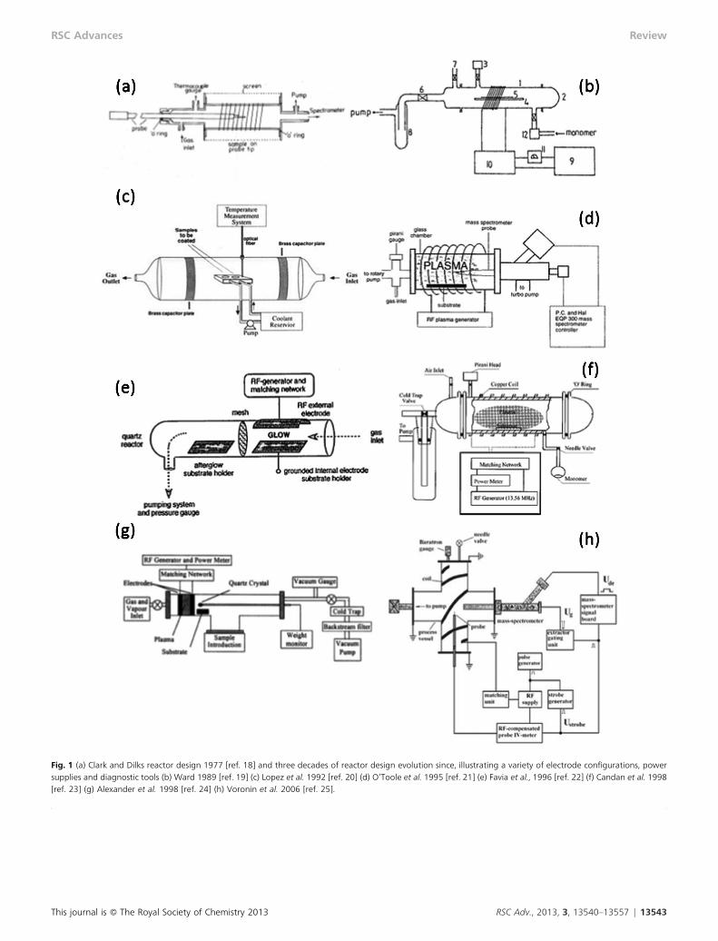
Fig. 1 (a) Clark and Dilks reactor design 1977 [ref. 18] and three decades of reactor design evolution since, illustrating a variety of electrode configurations, powersupplies and diagnostic tools (b) Ward 1989 [ref. 19] (c) Lopez et al. 1992 [ref. 20] (d) O’Toole et al. 1995 [ref. 21] (e) Favia et al., 1996 [ref. 22] (f) Candan et al. 1998[ref. 23] (g) Alexander et al. 1998 [ref. 24] (h) Voronin et al. 2006 [ref. 25].
This journal is � The Royal Society of Chemistry 2013 RSC Adv., 2013, 3, 13540–13557 | 13543
RSC Advances Review
tributing reasons for our ignorance of these in the context ofplasma-deposited functionalized films:
1. Plasma polymerization cuts across traditional disciplinaryareas of study (engineering, chemistry, physics, materialsscience, etc.) and therefore is not the preserve of any onecommunity.
2. The complexity of the problem and lack of tools to studythe problem may have been considered too daunting.
3. The technological application of these thin films hasraced ahead and generally coatings with the appropriateproperties can be obtained by trial-and-error.
4. Over simplification: studies which have been conductedto investigate the effects of the external parameters (such asdial power) on the final coating provide simple explanations,but do not take into account the physical processes takingplace within the plasma environment.
5. And finally, the erroneous perception that the mechan-isms have already been studied and adequately explained.
All of the above have led to the situation that persists today,where we believe there is an inadequate description of theprocesses leading to film formation, particularly in the contextof functionalized plasma polymer films. This is in contrast toconventional polymerization, where the pathways by whichpolymer chains grow are largely known and utilized in thedesign of new polymers; in plasma polymerization, coatings ofthe required properties are obtained by ‘trial-and-error’. Thelack of an adequate description means that researchers arerestricted in that they (i) can’t design films a priori and (ii)cannot reproduce the work of others using the sameparameters. Whilst (i) may never be entirely possible, (ii)should be and this has significantly limited exploitation ofplasma polymerization. There is also inconsistency betweenwork undertaken in different laboratories and reactors, andissues with both scaling-up and scaling-down plasma.
Since no two experimental systems are exactly the same andsmall differences in design can lead to large changes in, forexample, the coupled power, presently it is not possible todirectly cross correlate process or external parameters such asapplied power between systems. In the semi-conductor fieldthe Gaseous Electronics Conference (GEC) RF reference cellwas developed to eliminate such variation for workers usingetching plasmas.35 While this would seem to be a straightfor-ward exercise, even this proved to be non-trivial.36
This review concerns the basic principles of plasmapolymerization specifically in the context of functionalizedfilms. The most widely studied plasma polymers are thosearising from acrylic acid and its’ saturated analog propionicacid37 which can be used to produce functionalized organicfilms, in which the carboxylic acid group is ‘retained’ throughthe plasma polymerization processes and manifests in thefinal product, a thin-film coating. Other commonly producedfunctionalities of plasma polymer films include amines (e.g.allylamine38), alcohols (allyl alcohol39), fluorocarbons (hexa-fluoroethane40) and silicates (hexamethyl disiloxane41).
The following discussion is divided into three parts. In thefirst part, we consider the likely chemical processes that takeplace within the bulk of the plasma. We introduce some of thebasic concepts of plasmas, the range of chemical species
which may be encountered in plasmas, explain how they formafter ignition of the plasma and their typical properties.
In the second, we consider the physics, and relevant physicalprocesses that take place when a collecting surface is placed incontact with plasma. We investigate the processes that occur atthe plasma phase–surface interface, and introduce the conceptof formation of a sheath between these two regions. We alsodescribe a range of experimental techniques which may beused to probe the intrinsic properties of the plasma phase, andshow some experimental data demonstrating the essentialproperties of some typical plasmas.
In the third, we describe some common surface analysistechniques used to characterise plasma polymer films, anddiscuss how typical results can be reconciled with someproposed models for plasma polymer growth.
The plasma phase and chemical processes
Plasma consists of a mixture of electrons, ions, radicals,neutrals and photons. Some of these species are in localthermodynamic equilibrium, while others are not. Even forsimple gases like argon this mixture can be complex. Forplasmas of organic monomers, the complexity can rapidlyincrease as some components of the plasma fragment, whileothers interact and form larger species.
Two important concepts are the unit of energy and theaverage amount of energy that is adsorbed per molecule inplasma, Emean. An electron volt (eV) is defined as the amountof kinetic energy gained by an unbound electron when it loses1 V of electrical potential energy. This can be converted to atemperature using Boltzmann’s constant, k, giving:
1eV~1:6|10{19J
1:38|10{23JK-1~11600K (1)
For many of the charged species in plasmas, this unit ofenergy is convenient as it not only defines their temperature,but also the potential difference the species have enoughenergy to overcome.
The amount of energy absorbed per molecule is related tothe monomer flow rate, w, by eqn (2).
Emean~cP
w(2)
Where c is the duty cycle for pulsed plasmas, given by:
c~ton
tonztoff(2a)
For continuous wave plasma, this term reduces to 1.
Ignition
If we consider a gas at low pressure and ambient temperature,the gas molecules will typically be moving at 100–300 m s21. Alow degree of ionization may occur due to absorption of
13544 | RSC Adv., 2013, 3, 13540–13557 This journal is � The Royal Society of Chemistry 2013
Review RSC Advances
cosmic radiation42 and other random processes, giving rise toion-electron pairs. In the atmosphere at sea level, the electrondensity is approximately 5 6 1010 m23, or 1 ion–electron pairper 1015 neutral gas molecules;43 so under typical vacuumconditions used in plasma polymerization, the electrondensity, ne, is in the range of 105–107 m23 prior to ignitingthe plasma. When RF power is supplied to the system, themuch lighter electrons will be accelerated much more quicklythan the ions, and will gain kinetic energy (and heat) morereadily. Typically the ions will remain close to ambienttemperature, but the electrons will quickly reach temperaturesgreater than 10 000 K (y1 eV), with a very small proportionbeing in excess of 100 000 K (.10 eV). Thus the electrons arenot in thermal equilibrium with the ions and neutrals. Highenergy electrons can ionize neutral species in the gas phase bycolliding with them, producing an ion and another freeelectron. For a diatomic molecule X2, the reaction can bewritten as
e2 + X2 A 2e2 + X2+ (3)
Ionization of the molecule and release of a second electronresults in a cascade of electrons being introduced to the gasphase which in turn may lead to further ionization reactions.Of course ions and electrons may also recombine formingneutral molecules or be lost to the walls of the chamber, andeventually a steady state will be reached. As long as the RFpower is maintained, the population of ions and electrons willremain and a plasma phase will persist.
Plasma composition
Reduced pressure, low power plasmas used in the polymeriza-tion of volatile organic compounds comprise a weakly ionizedgas which is overall electrically neutral but contain positively-and negatively-charged particles, as well as neutrals andexcited state species, metastables and photons. Here we willdescribe the components of plasmas, how they arise and whatproperties they possess.
Electrons
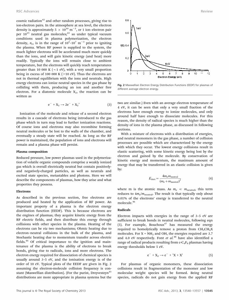
As described in the previous section, free electrons areproduced and heated by the application of RF power. Animportant property of a plasma is the electron energydistribution function (EEDF). This is because electrons arethe engines of plasmas; they acquire kinetic energy from theRF electric fields, and then distribute this energy throughcollisions with other species in the plasma. Heating of theelectrons can be via two mechanisms; Ohmic heating due toelectron–neutral collisions in the bulk of the plasma, andStochastic heating due to momentum transfer across electricfields.44 Of critical importance to the ignition and main-tenance of the plasma is the ability of electrons to breakbonds, giving rise to radicals, ions and more electrons. Theelectron energy required for dissociation of chemical species isusually around 3–5 eV, and the ionisation energy is of theorder of 10 eV. Typical plots of the EEDF are given in Fig. 2assuming the electron-molecule collision frequency is con-stant (Maxwellian distribution). (For the purist, Dreyvesteyn45
distributions are more appropriate in plasma systems but the
two are similar.) Even with an average electron temperature of4 eV, it can be seen that only a very small fraction of theelectrons have enough energy to ionize molecules, and onlyaround half have enough to dissociate molecules. For thisreason, the density of radical species is much higher than thedensity of ions in the plasma phase, as discussed in followingsections.
With a mixture of electrons with a distribution of energies,and neutral monomers in the gas phase, a number of collisionprocesses are possible which are characterized by the energywith which they occur. The lowest energy collisions result inelastic scattering, with some kinetic energy being lost by theelectron and gained by the molecule. By conservation ofkinetic energy and momentum, the maximum amount ofenergy that may be transferred in an elastic collision is givenby:
Emax~4memneutral
(mezmneutral)2
(4)
where m is the atomic mass. As me % mneutral, this termreduces to 4me/mneutral. The result is that typically only about0.01% of the electrons’ energy is transferred to the neutralmolecule.46
Radicals
Electron impacts with energies in the range of 3–5 eV aresufficient to break bonds in neutral molecules, following eqn(5). For example, Bouchoux47 has measured the energyrequired to homolytically remove a proton from CH3CH2Xmolecules. For X = NH2 and OH, the energies required are 3.7and 4.0 eV respectively. Font et al.48 have also identified arange of radical products resulting from c-C4F8 plasmas havingenergy thresholds below 5 eV.
e2 + X2 A e2 + ?X + X? (5)
For plasmas of organic monomers, these dissociationcollisions result in fragmentation of the monomer and lowmolecular weight species will be formed. Being neutralspecies, radicals do not gain energy from the applied RF
Fig. 2 Maxwellian Electron Energy Distribution Functions (EEDF) for plasmas ofdifferent average electron energy.
This journal is � The Royal Society of Chemistry 2013 RSC Adv., 2013, 3, 13540–13557 | 13545
RSC Advances Review
power, and therefore remain at or near ambient temperature.However, they are highly reactive as they have a spare electronwith which to covalently bond to other radical species, orneutral molecules containing a double bond.
The degree of fragmentation is an important considerationin plasma polymerization, particularly when the goal is to coata surface with a specific functional chemistry. For example,acrylic acid plasmas are frequently used to provide surfaceswith functional carboxylic acid groups. It has been convin-cingly shown that using low power acrylic acid plasma resultsin good retention of the carboxylic acid group.21 However, asthe RF input power is increased, fragmentation of themonomer species increases and functionality of the speciesin the plasma may be lost resulting in plasma polymers withlittle to no carboxylic acid groups.49
Radical species are of particular interest as they are thebuilding blocks in traditional polymerization. They are alsorelatively abundant in the plasma phase. Agarwal et al.50
measured the radical density of oxygen plasmas at around 1019
radicals m23, or approximately 1 for every 200 gas molecules inthe chamber. This value is probably an overestimate in thecontext of functionalized films as the power per molecule wasquite high, but demonstrates the relative abundance ofradicals in plasma. It has therefore long been assumed thatalong with neutrals, these radicals are the only species whichcontribute to plasma polymerization at surfaces. While these‘‘traditional’’ routes to forming plasma polymers are impor-tant, as we will discuss later they are not the only speciescapable of contributing mass to the plasma polymer.
Excited states, metastables and VUV
Higher energy collisions between electrons and neutral speciescan result in some kinetic energy being transferred from theelectron to the neutral molecule.46 This generally takes theform of an electron in the molecule being excited to a higherenergy orbit, as shown in eqn (6)
e2 + X2 A e2 + X2* (6)
where X2* represents an excited molecule. Excited molecules
are inherently unstable, and the electron will quickly fall backto its’ initial (ground) state in either one or more transitionsteps. Each transition step from high to low energy states isaccompanied by emission of a photon,
X2* A h0 + X23 (7)
where X23 represents a lower level excited state (not necessarilyground state), and h0 a photon of energy equal to thedifference between the two states. Some of these photons willbe in the visible region of the electromagnetic spectrum, andgive rise to the characteristic glow of the discharge. Higherenergy photons are also possible resulting in vacuum ultra-violet (VUV). VUV radiation may then also dissociate andionize molecules if the photons are of sufficient energy.
These excited molecules are typically not very long lived, andwill return to the ground state in a time of the order of 10 ns.
However, some of these molecules may reach a metastablestate which may last for 1 ms or longer.
Ions
The traditional view is that ions are created by high energycollisions between electrons and molecules, above approxi-mately 10 eV, which result in ionization of the molecules andliberation of secondary electrons as shown in eqn (3). It hasalso been shown recently in Selected Ion Flow Tube (SIFT)experiments that ionization may result from collisionsbetween neutral molecules and H3O+ ions.51 For this reactionscheme, a proton is transferred from the H3O+ ion to theneutral molecule, N.
H3O+ + N A H2O + NH+ (8)
The source of H3O+ is adsorbed water on the walls of thechamber being removed by ion bombardment which isdescribed in detail later.
Thus, overall charge neutrality is conserved but local spacecharges may develop. While ions are charged and thereforeaffected by the electric fields produced by the RF power used toignite and maintain the plasma, they are massive relative toelectrons. Consequently ions do not accelerate and gain energyin the way that electrons do, and so remain roughly inthermodynamic equilibrium with the radical and metastablespecies.
An important property of the plasma is the plasma density,which is the density of ionized species in the plasma phase, ni.The number of charged species per unit volume and thetemperature of these species is influenced by the plasmareactor design, the operating pressure, power source andmode of power coupling. Typically for the RF plasma systemsused in plasma polymerization, the plasma density is in therange of 1013–1016 ions m23.32 This compares with the neutraldensity of the plasma phase which is usually 1019–1021
molecules m23. Therefore ions are relatively scarce in theplasma phase, with typically 104–105 gas molecules for eachion particle. As a consequence, the role of ions in plasmapolymer formation has historically been discounted. Morerecently, experimental data has become available whichindicates that ions may play a much greater role in both theplasma phase and surface polymerization than has beenaccepted. Reasons for greater ion involvement are discussedlater.
Reactions in the plasma phase
Once the various species mentioned above have been initiatedin the plasma, reactions may take place between these species.The obvious candidates are the excited molecules, radicals andions. Previous textbooks and reviews of plasma, for instanceChapman46 and Lieberman and Lichtenberg,52 and of plasmapolymerization53 have considered the likely chemical specieswithin plasmas that give rise to film growth. Notwithstandingthe influence of plasma power (power in the plasma and itsdistribution) power source (usually radio frequency at 13.56MHz in the context of the functional film growth), powercoupling, gas flow rate and pressure and finally reactor design,it is believed that in the plasma there will a complex mixture of
13546 | RSC Adv., 2013, 3, 13540–13557 This journal is � The Royal Society of Chemistry 2013
Review RSC Advances
species including the starting compound, larger species builtup from the starting compound and fragments of the startingcompound. These species will be neutral (ground or excitedstate), radical or charged (cations, anions and electrons).
Below, we briefly consider the likely types of reactions thattake place within the plasma bulk, and whilst others haveascribed film growth (exclusively) to radical processes, we startfrom the premise that we should examine (again) the relativeimportance of any particular pathway in film growth offunctionalised plasma polymers.
Within the bulk of the plasma we would consider fivegeneral 2-body reactions which may occur (excluding neutral-neutral reactions). In order of decreasing cross sectional areathey are:
?R + N A ?R 2 N (radical) (9a)
?R + R?A N 2 N (neutral) or ?R 2 R? (diradical) (9b)
I + N A I 2 N (ion) (9c)
I + R? A I 2 R? (ion) (9d)
I + I A N (neutral) (9e)
where ?R = any radical species, N = any neutral species (groundstate or excited) and I = any ionic species (positively ornegatively charged).
3-body collisions are also possible, where the involvement ofthe third body allows any excess energy to be dissipated.46 Thethird body is often the walls of the chamber (which obviouslyhas a large cross sectional area relative to the molecules!) Inthe bulk of the plasma which we are considering here however,the likelihood of 3-body collisions occurring is very low.
The reaction between ?R + N (irrespective of the nature of N,unsaturated or saturated) results in a further radical, andwhere N contains a carbon double bond in some instancesthere is the possibility of ‘‘chain growth’’ polymerization.However, care is required in assigning polymerization to chaingrowth just because there is a carbon double bond, as forexample allylic compounds will not readily polymerize in thisfashion.3,54
In the case of ?R + R?, the resultant species will either be a di-radical (presumably still reactive) or the radical centrescombine and the result is a neutral, in which case for furtherreactions to occur the resultant species will need to bereactivated by the plasma. Both ?R + N and ?R + R? areexothermic and readily proceed with high rate constants. Forexample, the radical–neutral rate constant for acetyleneplasmas has been estimated at 4 6 10211 cm3 s21.55
As ions are scarce in low temperature, low pressure plasmasit has been generally accepted until recently that reactionsinvolving ions in the plasma phase could be discounted.However, given that greater than 99% of the molecules in theplasma chamber are neutral species, the cross sectional areafor I + N collisions is relatively high. It is also important to noteI + N has a very high rate constant. Indeed, O’Toole et al.39
have measured the (M–H+ + M) rate constant for allyl alcoholas being 2.1 6 1029 cm3 s21, similar to the collisional rate
coefficient. Reactions I + N and I + R? result in larger ionicspecies, while I + I may result in neutral species if the ions areof opposite charge. In this case, while the collision crosssection is extremely low, the rate constant is very high. Stoykovet al.56 have measured the ion-ion recombination rate constantat around 1 6 1027 cm3 s21 for acetylene plasmas.
As will be discussed later, there is mounting experimentalevidence that reactions involving ions occur in the plasmaphase, leading to molecular rearrangements which manifestthemselves in the plasma polymer formed on a surface.
Plasma analysis
Therefore, from the above discussion, it can be seen that theplasma phase is a complex mixture of electrons (with variousenergies), metastables, excited molecules, photons, radicalsand ions (of various molecular weights). A comprehensivedescription of the state of the plasma is therefore difficult andrequires a great deal of information. In this section we point tothe important parameters that may be measured in theplasma, and outline the techniques available for obtainingthese data.
The electrons are the workhorses of the plasma, andtherefore are an important consideration in describingplasmas. Of interest are the electron density, ne, and electrontemperature, Te. For most plasma systems, the ions that areproduced are positively charged and so the electron density isthe same as the ion density, ni. It should be noted this is notalways the case, as for example monomers containing fluorinecan produce negative ions.57 However, assuming all negativecharges in the plasma are electrons, measuring the electrondensity gives the positive charge density. As the electrons arenot in thermodynamic equilibrium with the rest of the speciesin the plasma, the electron temperature must be indepen-dently measured.
The fragmentation of species in the plasma phase is alsocritical. This is particularly so when retention of functionalgroups is important and therefore measuring the degree offragmentation and oligomerization in the plasma affordssome insight into the plasma chemistry.
Langmuir probe
In its’ simplest form, a Langmuir probe consists of anelectrode placed in contact with a plasma.58 The voltage (V)of the electrode relative to the surrounding vessel can bevaried and the resulting current (I) can be measured. From theV–I characteristic of the probe, various parameters of theplasma can be calculated, including the electron temperature,plasma density and the plasma potential (Vp, discussedlater).59
Care must be taken, as the probe draws electrons from theplasma, and therefore may affect the plasma locally. Thiseffect is usually minimized by keeping the probe area small,although it is sometimes overcome by using a doubleprobe.60,61 Geometrical effects are also known as the collectionarea of the probe is actually the sheath area surrounding theprobe (sheaths are discussed later) which depends on the
This journal is � The Royal Society of Chemistry 2013 RSC Adv., 2013, 3, 13540–13557 | 13547
RSC Advances Review
plasma density. Finally, for depositing plasmas, an insulatingdeposit quickly reduces the effective area of the probe andtherefore its’ effectiveness. This may be overcome by heatingthe probe to ‘‘burn off’’ any deposit as it forms.
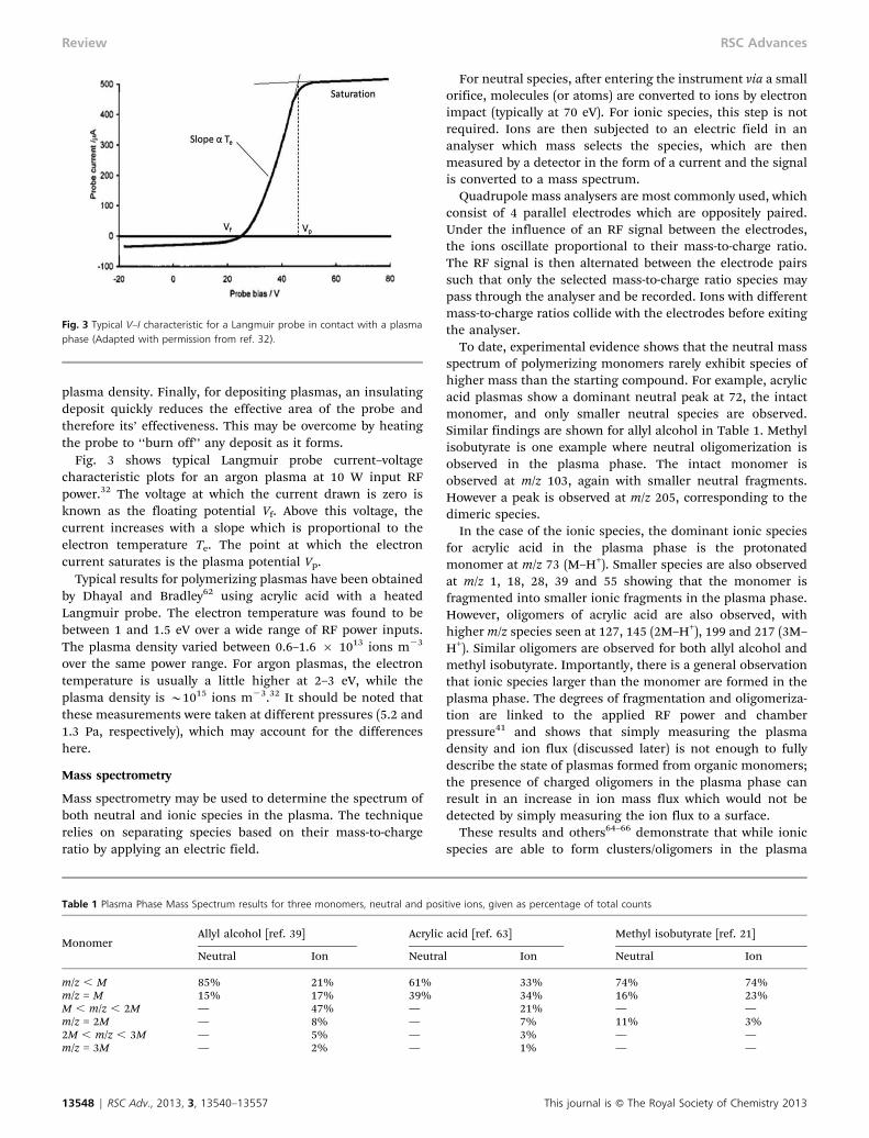
Fig. 3 shows typical Langmuir probe current–voltagecharacteristic plots for an argon plasma at 10 W input RFpower.32 The voltage at which the current drawn is zero isknown as the floating potential Vf. Above this voltage, thecurrent increases with a slope which is proportional to theelectron temperature Te. The point at which the electroncurrent saturates is the plasma potential Vp.
Typical results for polymerizing plasmas have been obtainedby Dhayal and Bradley62 using acrylic acid with a heatedLangmuir probe. The electron temperature was found to bebetween 1 and 1.5 eV over a wide range of RF power inputs.The plasma density varied between 0.6–1.6 6 1013 ions m23
over the same power range. For argon plasmas, the electrontemperature is usually a little higher at 2–3 eV, while theplasma density is y1015 ions m23.32 It should be noted thatthese measurements were taken at different pressures (5.2 and1.3 Pa, respectively), which may account for the differenceshere.
Mass spectrometry
Mass spectrometry may be used to determine the spectrum ofboth neutral and ionic species in the plasma. The techniquerelies on separating species based on their mass-to-chargeratio by applying an electric field.
For neutral species, after entering the instrument via a smallorifice, molecules (or atoms) are converted to ions by electronimpact (typically at 70 eV). For ionic species, this step is notrequired. Ions are then subjected to an electric field in ananalyser which mass selects the species, which are thenmeasured by a detector in the form of a current and the signalis converted to a mass spectrum.
Quadrupole mass analysers are most commonly used, whichconsist of 4 parallel electrodes which are oppositely paired.Under the influence of an RF signal between the electrodes,the ions oscillate proportional to their mass-to-charge ratio.The RF signal is then alternated between the electrode pairssuch that only the selected mass-to-charge ratio species maypass through the analyser and be recorded. Ions with differentmass-to-charge ratios collide with the electrodes before exitingthe analyser.
To date, experimental evidence shows that the neutral massspectrum of polymerizing monomers rarely exhibit species ofhigher mass than the starting compound. For example, acrylicacid plasmas show a dominant neutral peak at 72, the intactmonomer, and only smaller neutral species are observed.Similar findings are shown for allyl alcohol in Table 1. Methylisobutyrate is one example where neutral oligomerization isobserved in the plasma phase. The intact monomer isobserved at m/z 103, again with smaller neutral fragments.However a peak is observed at m/z 205, corresponding to thedimeric species.
In the case of the ionic species, the dominant ionic speciesfor acrylic acid in the plasma phase is the protonatedmonomer at m/z 73 (M–H+). Smaller species are also observedat m/z 1, 18, 28, 39 and 55 showing that the monomer isfragmented into smaller ionic fragments in the plasma phase.However, oligomers of acrylic acid are also observed, withhigher m/z species seen at 127, 145 (2M–H+), 199 and 217 (3M–H+). Similar oligomers are observed for both allyl alcohol andmethyl isobutyrate. Importantly, there is a general observationthat ionic species larger than the monomer are formed in theplasma phase. The degrees of fragmentation and oligomeriza-tion are linked to the applied RF power and chamberpressure41 and shows that simply measuring the plasmadensity and ion flux (discussed later) is not enough to fullydescribe the state of plasmas formed from organic monomers;the presence of charged oligomers in the plasma phase canresult in an increase in ion mass flux which would not bedetected by simply measuring the ion flux to a surface.
These results and others64–66 demonstrate that while ionicspecies are able to form clusters/oligomers in the plasma
Table 1 Plasma Phase Mass Spectrum results for three monomers, neutral and positive ions, given as percentage of total counts
MonomerAllyl alcohol [ref. 39] Acrylic acid [ref. 63] Methyl isobutyrate [ref. 21]
Neutral Ion Neutral Ion Neutral Ion
m/z , M 85% 21% 61% 33% 74% 74%m/z = M 15% 17% 39% 34% 16% 23%M , m/z , 2M — 47% — 21% — —m/z = 2M — 8% — 7% 11% 3%2M , m/z , 3M — 5% — 3% — —m/z = 3M — 2% — 1% — —
Fig. 3 Typical V–I characteristic for a Langmuir probe in contact with a plasmaphase (Adapted with permission from ref. 32).
13548 | RSC Adv., 2013, 3, 13540–13557 This journal is � The Royal Society of Chemistry 2013
Review RSC Advances
phase, generally neutral and radical species do not react toform larger molecules. It should be noted that we cannotpreclude these reactions from occurring at the surface.
Optical emission spectroscopy (OES)
OES is a non-invasive technique for probing the plasma phase,and can be used to obtain information about the plasma inreal-time,67 and has been proposed as a semi-quantitativetechnique for process control.68,69 The electron temperatureand density may also be calculated from the optical emissionspectra.70 As discussed above, excited species in the plasmaemit photons as they relax to their ground state. Some of thesephotons are in the visible part of the spectrum, and typicallyspectra are recorded for wavelengths between 200–1000 nm.There is extensive data available for transitions of neutralargon species,71,72 but the most intense peaks occur in the red/near-infrared region between 690 and 900 nm relating to thetransitions 3p54p to 3p54s.73
For depositing plasmas, the emission spectra may be quitecomplex. For example, Pappas and Hopwood74 measured thespectra of methane plasmas and observed many peaksbetween 375–525 nm assigned to various states of carbonand hydrogen. The relative intensities of these peaks changedmarkedly with applied RF power. Booth and Corr75 measuredthe spectra of CF4 plasmas and again observed a richchemistry of carbon and fluorine. They also observed thatmany of these species persisted after the plasma was turnedoff for up to 1.5 ms for some species. Similarly, Corr et al.76
measured the spectra of downstream nitrogen/trimethylgal-lium plasma and observed strong peaks associated with Gaand CN species.
Physics at the plasma–surface interface
Now we have described the components of the plasma phaseand some of their properties, we can move onto how thesecomponents interact with a surface placed in contact with theplasma.
Generation of electrical potentials
The fluxes, J, due to thermal motion of all species in theplasma phase to an imaginary plane from one side only aregiven by:
Ji = 0.25 nivi (10a)
Je = 0.25 neve (10b)
Jrad = 0.25 nradvrad (10c)
Jneutrals = 0.25 nneutralsvneutrals (10d)
where the thermal velocity of the particles, v, is given by
n~
ffiffiffiffiffiffiffiffiffi
8kT
pm
r
(10e)
and T is the absolute temperature.46 For the radical andneutral species, eqn (10c) and (10d) hold true in plasma. Ions
and electrons on the other hand obviously react to electricfields which can alter both their density and velocity. Anyinsulating or electrically isolated surface will assume apotential such that the fluxes of positive (ions) and negative(electrons) charge carriers arriving at the surface will be equal.As discussed previously, when the plasma is ignited, theelectrons gain significant kinetic energy due to the appliedelectric fields, however the ions remain relatively cold.
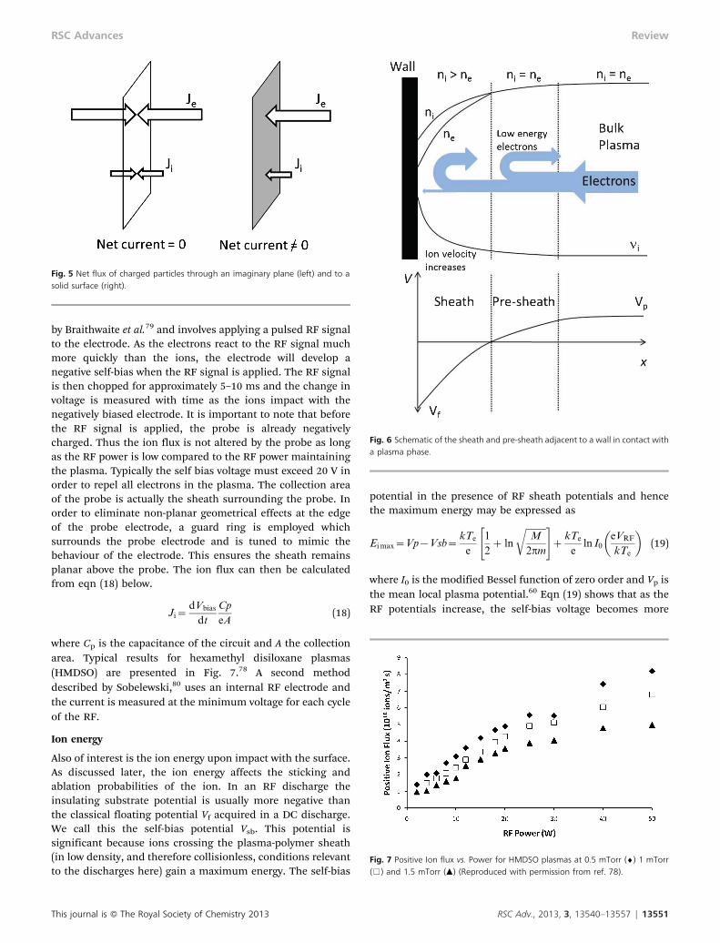
If we consider just the ions and electrons, overall electro-neutrality is conserved, ni = ne, however the electron velocity isfar greater than the ion velocity as they are both hotter andlighter. Therefore, Je & Ji. If we consider an imaginary plane inFig. 5, the flux of particles to the plane from one side isbalanced by the flux of particles from the other, and the netcurrent is zero. This is the case in the bulk of the plasma. If theimaginary plane is replaced with a solid surface (such as a wallof the chamber), the particles cannot pass through the plane,and there is a net flow of negative charge as the electron flux isgreater than the ion flux. This causes the plasma to develop apositive potential relative to ground, known as Vp, and asurface placed in contact with the plasma will develop anegative potential relative to the plasma. The negativepotential developed at the surface will then begin to attractpositive ions from the plasma (Ji increases), and simulta-neously repel electrons (Je decreases). This process willcontinue until equilibrium between the ion flux and electronflux is achieved. The potential of the surface is then known asthe floating potential, Vf, and for a DC discharge the potentialbetween the plasma and the surface is given by
Vp{Vf~kTe
e
1
2z ln
ffiffiffiffiffiffiffiffiffi
M
2pm
r
" #
(11)
The questions that remain are how the potential variesbetween the plasma bulk and the surface, and how this affectsthe various components of the plasma phase. We shall see thatthere are two regions which must be addressed; a regionadjacent to the surface called the sheath, and a region betweenthe sheath and the bulk plasma known as the pre-sheath.
The sheath
As the surface develops a negative potential, close to thesurface the electron density will be greatly reduced comparedto the bulk plasma, with only high energy electrons able toreach the surface (Fig. 6). Therefore the space adjacent to thesurface will develop a net positive charge. This space is knownas the sheath. The density of this net positive charge decreasesas we move further from the surface. At some point, theelectron and ion densities become equal and the net spacecharge is zero, which marks the outer edge of the sheath. Theelectron distribution with respect to the distance from thewall, x, in the sheath is given by the Boltzmann distribution
ne(x)~ne expeV (x)
kTe
� �
(12)
This journal is � The Royal Society of Chemistry 2013 RSC Adv., 2013, 3, 13540–13557 | 13549
RSC Advances Review
Poisson’s eqn (13) can be used in electrostatics to determinethe variation of potential in regions of space charge.
+2Q~{r
e0
(13)
where Q is the potential, r is the density, and e0 is thepermittivity of a vacuum. The important outcome though isobtained by combining this with the Boltzmann distribution,giving:
DV (x)~DV0 exp{x
lD
� �
(14)
where lD~
ffiffiffiffiffiffiffiffiffiffiffiffi
kTee0
nee2
s
(14a)
lD is known as the Debye length, and determines the lengthscale over which the voltage drops with the distance from thesurface. This sheath region usually extends between 20 and100 mm from the surface into the plasma. Once positive ionsare in the sheath, they are trapped by the negative potential ofthe surface and cannot escape unless they collide with otheratoms.
Pre-sheath
Within the sheath, ions convert electrical potential energy intokinetic energy as they approach the negatively charged surface.For ion energy conservation:
1
2Mv(x)2~
1
2Mv2{eV (x) (15)
As the positive ions accelerate, they spread out and theirdensity decreases. Electrons on the other hand are repelledfrom the surface and ejected from the sheath, and alsodecrease in density following the Boltzmann distribution.However, for the sheath to remain a stable region of positivespace charge, the local electron density must always be lessthan ion density. Also, at the sheath edge, by definition, theion and electron densities must be equal. The solution forthese conditions was identified by David Bohm in 1949 and isthat the ions must enter the sheath with a speed greater than(kTe/m)1/2, known as the Bohm velocity.77 Therefore, thereexists a region between the sheath and the bulk plasma whereions are accelerated to the Bohm velocity, known as the pre-sheath. In this region, the ion and electron densities are equal,but lower than the bulk plasma as ions are accelerated and lowenergy electrons are repelled from the surface. This is knownas the Bohm Sheath Criterion.
The Bohm Sheath Criterion has a number of consequencesfor the plasma system. The most important for low tempera-ture plasma polymerization is an increase in the flux of ions tothe surface. If we consider the ions enter the pre-sheath withnegligible energy, it can be shown that the ion flux at thesheath edge is:
Ji~ exp {1
2
� �
ni
ffiffiffiffiffiffiffiffi
kTe
mi
s
(16)
Note that the ion flux to the surface is determined by theelectron temperature, not the ion temperature. This is becausethe flux of electrons to the surface is determined by thenumber of electrons with enough energy to overcome thenegative surface potential. For charge equilibrium to bemaintained, this electron flux at the surface must be balancedby the flux of ions into the sheath.
For typical values of plasma density (1013–1015 ions m23)and electron temperature (2–4 eV), typical ion fluxes are in therange of 1–6 6 1018 ions m22 s21. This result is quite differentto the thermal ion flux of 0.25nivi, often being at least an orderof magnitude larger, an effect which has often been neglectedwhen considering plasma polymerisation.
If we calculate the ratio of the ion flux to a surface in eqn(16), to the thermal flux of ions to an imaginary plane (fromone side only, eqn (10a)), we get:
Ji
Jt
~ffiffiffiffiffiffi
2pp
exp {1
2
� �
ffiffiffiffiffi
Te
Ti
r
(17)
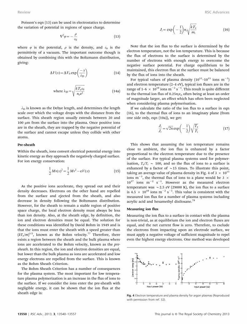
This shows that assuming the ion temperature remainsclose to ambient, the ion flux is enhanced by a factorproportional to the electron temperature due to the presenceof the surface. For typical plasma systems used for polymer-isation, Te/Ti y 100, and so the flux of ions to a surface isenhanced by a factor of y15 times. To illustrate this point,taking an average value of plasma density in Fig. 4 of 3 6 1015
ions m23, the thermal flux of ions to a plane would be 3 61017 ions m22 s21. However as the measured electrontemperature was y2.5 eV (29000 K), the ion flux to a surfaceis 4.5 6 1018 ions m22 s21. This value is consistent with themeasured ion flux for a number of plasma systems includingacrylic acid and hexamethyl disiloxane.78
Measuring ion flux
Measuring the ion flux to a surface in contact with the plasmais non-trivial, as at equilibrium the ion and electron fluxes areequal, and the net current flow is zero. Therefore, to excludethe electrons from impacting upon an electrode surface, wemust apply a negative voltage of sufficient magnitude to repeleven the highest energy electrons. One method was developed
Fig. 4 Electron temperature and plasma density for argon plasmas (Reproducedwith permission from ref. 32).
13550 | RSC Adv., 2013, 3, 13540–13557 This journal is � The Royal Society of Chemistry 2013
Review RSC Advances
by Braithwaite et al.79 and involves applying a pulsed RF signalto the electrode. As the electrons react to the RF signal muchmore quickly than the ions, the electrode will develop anegative self-bias when the RF signal is applied. The RF signalis then chopped for approximately 5–10 ms and the change involtage is measured with time as the ions impact with thenegatively biased electrode. It is important to note that beforethe RF signal is applied, the probe is already negativelycharged. Thus the ion flux is not altered by the probe as longas the RF power is low compared to the RF power maintainingthe plasma. Typically the self bias voltage must exceed 20 V inorder to repel all electrons in the plasma. The collection areaof the probe is actually the sheath surrounding the probe. Inorder to eliminate non-planar geometrical effects at the edgeof the probe electrode, a guard ring is employed whichsurrounds the probe electrode and is tuned to mimic thebehaviour of the electrode. This ensures the sheath remainsplanar above the probe. The ion flux can then be calculatedfrom eqn (18) below.
Ji~dVbias
dt
Cp
eA(18)
where Cp is the capacitance of the circuit and A the collectionarea. Typical results for hexamethyl disiloxane plasmas(HMDSO) are presented in Fig. 7.78 A second methoddescribed by Sobelewski,80 uses an internal RF electrode andthe current is measured at the minimum voltage for each cycleof the RF.
Ion energy
Also of interest is the ion energy upon impact with the surface.As discussed later, the ion energy affects the sticking andablation probabilities of the ion. In an RF discharge theinsulating substrate potential is usually more negative thanthe classical floating potential Vf acquired in a DC discharge.We call this the self-bias potential Vsb. This potential issignificant because ions crossing the plasma-polymer sheath(in low density, and therefore collisionless, conditions relevantto the discharges here) gain a maximum energy. The self-bias
potential in the presence of RF sheath potentials and hencethe maximum energy may be expressed as
Ei max~Vp{Vsb~kTe
e
1
2z ln
ffiffiffiffiffiffiffiffiffi
M
2pm
r
" #
zkTe
eln I0
eVRF
kTe
� �
(19)
where I0 is the modified Bessel function of zero order and Vp isthe mean local plasma potential.60 Eqn (19) shows that as theRF potentials increase, the self-bias voltage becomes more
Fig. 5 Net flux of charged particles through an imaginary plane (left) and to asolid surface (right).
Fig. 6 Schematic of the sheath and pre-sheath adjacent to a wall in contact witha plasma phase.
Fig. 7 Positive Ion flux vs. Power for HMDSO plasmas at 0.5 mTorr (¤) 1 mTorr(%) and 1.5 mTorr (m) (Reproduced with permission from ref. 78).
This journal is � The Royal Society of Chemistry 2013 RSC Adv., 2013, 3, 13540–13557 | 13551
RSC Advances Review
negative. Furthermore, for large RF amplitudes, (VRF & kTe/e)ln I0(x) is almost a linear function and the second term on theright-hand side of eqn (19) approximates to VRF and theexpression reduces to:
Ei max = Vp 2 Vsb = VRF (20)
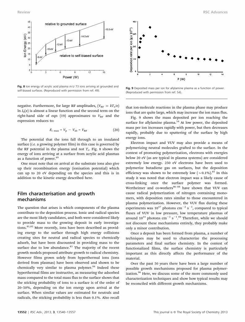
The potential that the ions fall through to an insulatedsurface (i.e. a growing polymer film) in this case is governed bythe RF potential in the plasma and not Te. Fig. 8 shows theenergy of ions arriving at a surface from acrylic acid plasmasas a function of power.49
One must note that on arrival at the substrate ions also giveup their recombination energy (ionisation potential) whichcan up to 20 eV depending on the species and this is inaddition to the kinetic energy described here.
Film characterisation and growthmechanisms
The question that arises is which components of the plasmacontribute to the deposition process. Ionic and radical speciesare the most likely candidates, and both were considered likelyto provide mass to the growing deposit in early investiga-tions.81,82 More recently, ions have been described as provid-ing energy to the surface through high energy collisionscreating sites for neutral and radical species to chemicallyadsorb, but have been discounted in providing mass to thesurface due to low abundance.83 The majority of the recentgrowth models proposed attribute growth to radical chemistry.However films grown solely from hyperthermal ions (ionsderived from plasmas) have been observed and shown to bechemically very similar to plasma polymer.84 Indeed thesehyperthermal films are instructive, as measuring the adsorbedmass compared to the total mass flux to the surface shows thatthe sticking probability of ions to a surface is of the order of20–50%, depending on the ion energy upon arrival at thesurface. When similar values are estimated for neutrals andradicals, the sticking probability is less than 0.1%. Also recall
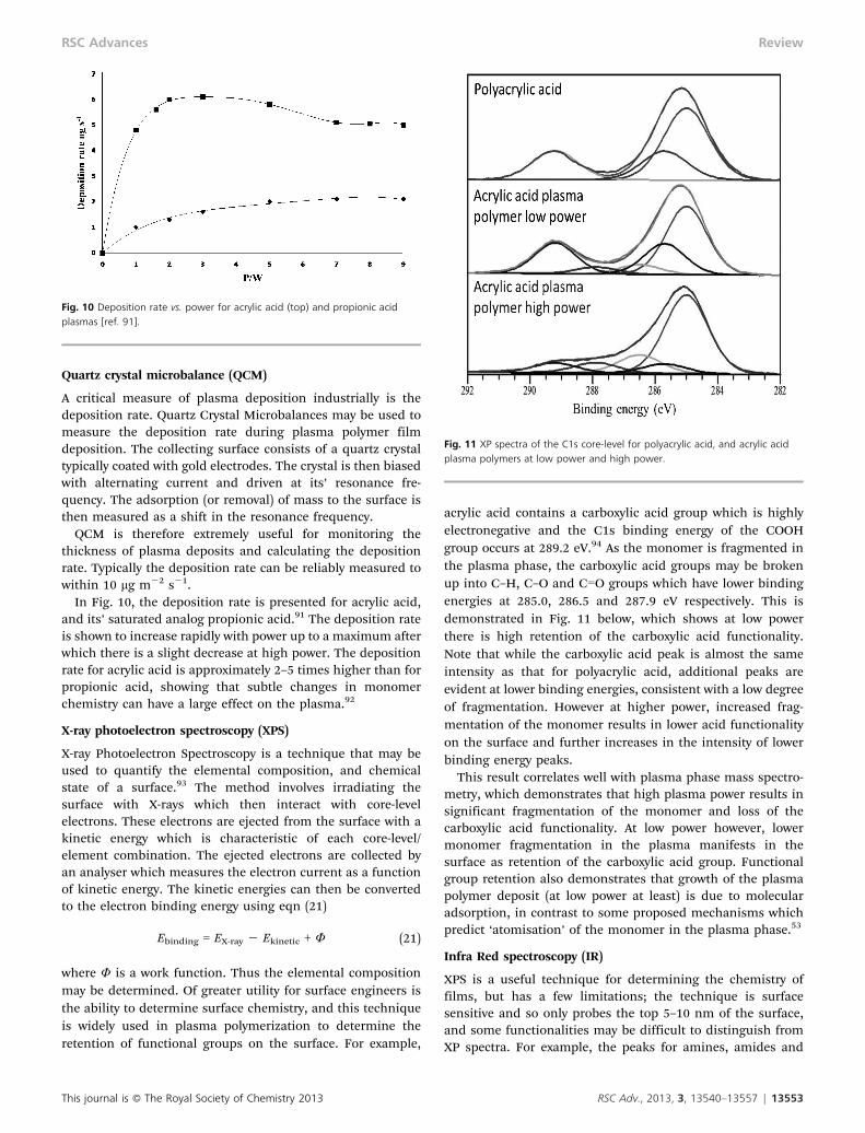
that ion-molecule reactions in the plasma phase may produceions that are quite large, which may increase the ion mass flux.
Fig. 9 shows the mass deposited per ion reaching thesurface for allylamine plasma.54 At low power, the depositedmass per ion increases rapidly with power, but then decreasesrapidly, probably due to sputtering of the surface by highenergy ions.
Electron impact and VUV may also provide a means ofpolymerizing neutral molecules grafted to the surface. In thecontext of promoting polymerization, electrons with energiesbelow 20 eV (as are typical in plasma systems) are consideredextremely low energy. 250 eV electrons have been used topolymerize butadiene gas on surfaces, but the depositionefficiency was shown to be extremely low (y0.1%).85 In thisstudy it was noted that electron impact was a likely cause ofcross-linking once the surface polymer was formed.Wertheimer and co-workers86–88 have shown that VUV cancause radical polymerization of nitrogen containing mono-mers, with deposition rates similar to those encountered inplasma polymerization. However, the VUV flux during theseexperiments was 1017 photons cm22 s21, compared to typicalfluxes of VUV in low pressure, low temperature plasmas ofaround 1014 photons cm22 s21.89 Therefore, while we shouldnot discount these mechanisms entirely, they probably makeonly a minor contribution.
Once a deposit has been formed from plasma, a number oftechniques may be used to characterize the processingparameters and final surface chemistry. In the context offunctionalized films, the surface chemistry is particularlyimportant as this directly affects the performance of thematerial.
Over the past 50 years there have been a large number ofpossible growth mechanisms proposed for plasma polymer-ization.90 Here, we discuss some of the more commonly usedcharacterization techniques and show how typical results maybe reconciled with different growth mechanisms.
Fig. 8 Ion energy of acrylic acid plasma m/z 73 ions arriving at grounded andself-biased surfaces. (Reproduced with permission from ref. 49).
Fig. 9 Deposited mass per ion for allylamine plasma as a function of power.(Reproduced with permission from ref. 54).
13552 | RSC Adv., 2013, 3, 13540–13557 This journal is � The Royal Society of Chemistry 2013
Review RSC Advances
Quartz crystal microbalance (QCM)
A critical measure of plasma deposition industrially is thedeposition rate. Quartz Crystal Microbalances may be used tomeasure the deposition rate during plasma polymer filmdeposition. The collecting surface consists of a quartz crystaltypically coated with gold electrodes. The crystal is then biasedwith alternating current and driven at its’ resonance fre-quency. The adsorption (or removal) of mass to the surface isthen measured as a shift in the resonance frequency.
QCM is therefore extremely useful for monitoring thethickness of plasma deposits and calculating the depositionrate. Typically the deposition rate can be reliably measured towithin 10 mg m22 s21.
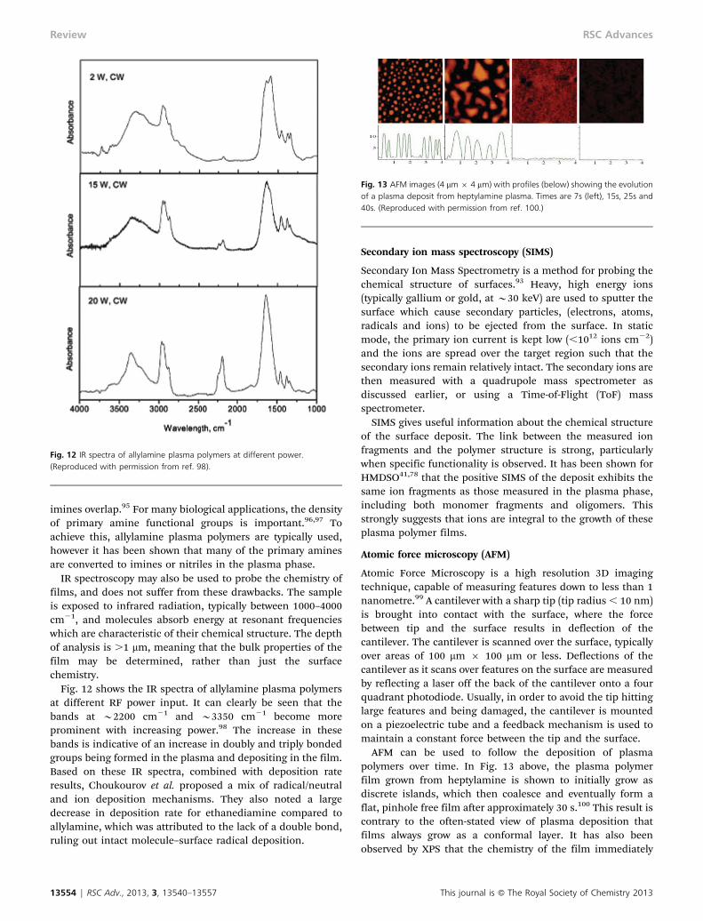
In Fig. 10, the deposition rate is presented for acrylic acid,and its’ saturated analog propionic acid.91 The deposition rateis shown to increase rapidly with power up to a maximum afterwhich there is a slight decrease at high power. The depositionrate for acrylic acid is approximately 2–5 times higher than forpropionic acid, showing that subtle changes in monomerchemistry can have a large effect on the plasma.92
X-ray photoelectron spectroscopy (XPS)
X-ray Photoelectron Spectroscopy is a technique that may beused to quantify the elemental composition, and chemicalstate of a surface.93 The method involves irradiating thesurface with X-rays which then interact with core-levelelectrons. These electrons are ejected from the surface with akinetic energy which is characteristic of each core-level/element combination. The ejected electrons are collected byan analyser which measures the electron current as a functionof kinetic energy. The kinetic energies can then be convertedto the electron binding energy using eqn (21)
Ebinding = EX-ray 2 Ekinetic + W (21)
where W is a work function. Thus the elemental compositionmay be determined. Of greater utility for surface engineers isthe ability to determine surface chemistry, and this techniqueis widely used in plasma polymerization to determine theretention of functional groups on the surface. For example,
acrylic acid contains a carboxylic acid group which is highlyelectronegative and the C1s binding energy of the COOHgroup occurs at 289.2 eV.94 As the monomer is fragmented inthe plasma phase, the carboxylic acid groups may be brokenup into C–H, C–O and CLO groups which have lower bindingenergies at 285.0, 286.5 and 287.9 eV respectively. This isdemonstrated in Fig. 11 below, which shows at low powerthere is high retention of the carboxylic acid functionality.Note that while the carboxylic acid peak is almost the sameintensity as that for polyacrylic acid, additional peaks areevident at lower binding energies, consistent with a low degreeof fragmentation. However at higher power, increased frag-mentation of the monomer results in lower acid functionalityon the surface and further increases in the intensity of lowerbinding energy peaks.
This result correlates well with plasma phase mass spectro-metry, which demonstrates that high plasma power results insignificant fragmentation of the monomer and loss of thecarboxylic acid functionality. At low power however, lowermonomer fragmentation in the plasma manifests in thesurface as retention of the carboxylic acid group. Functionalgroup retention also demonstrates that growth of the plasmapolymer deposit (at low power at least) is due to molecularadsorption, in contrast to some proposed mechanisms whichpredict ‘atomisation’ of the monomer in the plasma phase.53
Infra Red spectroscopy (IR)
XPS is a useful technique for determining the chemistry offilms, but has a few limitations; the technique is surfacesensitive and so only probes the top 5–10 nm of the surface,and some functionalities may be difficult to distinguish fromXP spectra. For example, the peaks for amines, amides and
Fig. 10 Deposition rate vs. power for acrylic acid (top) and propionic acidplasmas [ref. 91].
Fig. 11 XP spectra of the C1s core-level for polyacrylic acid, and acrylic acidplasma polymers at low power and high power.
This journal is � The Royal Society of Chemistry 2013 RSC Adv., 2013, 3, 13540–13557 | 13553
RSC Advances Review
imines overlap.95 For many biological applications, the densityof primary amine functional groups is important.96,97 Toachieve this, allylamine plasma polymers are typically used,however it has been shown that many of the primary aminesare converted to imines or nitriles in the plasma phase.
IR spectroscopy may also be used to probe the chemistry offilms, and does not suffer from these drawbacks. The sampleis exposed to infrared radiation, typically between 1000–4000cm21, and molecules absorb energy at resonant frequencieswhich are characteristic of their chemical structure. The depthof analysis is .1 mm, meaning that the bulk properties of thefilm may be determined, rather than just the surfacechemistry.
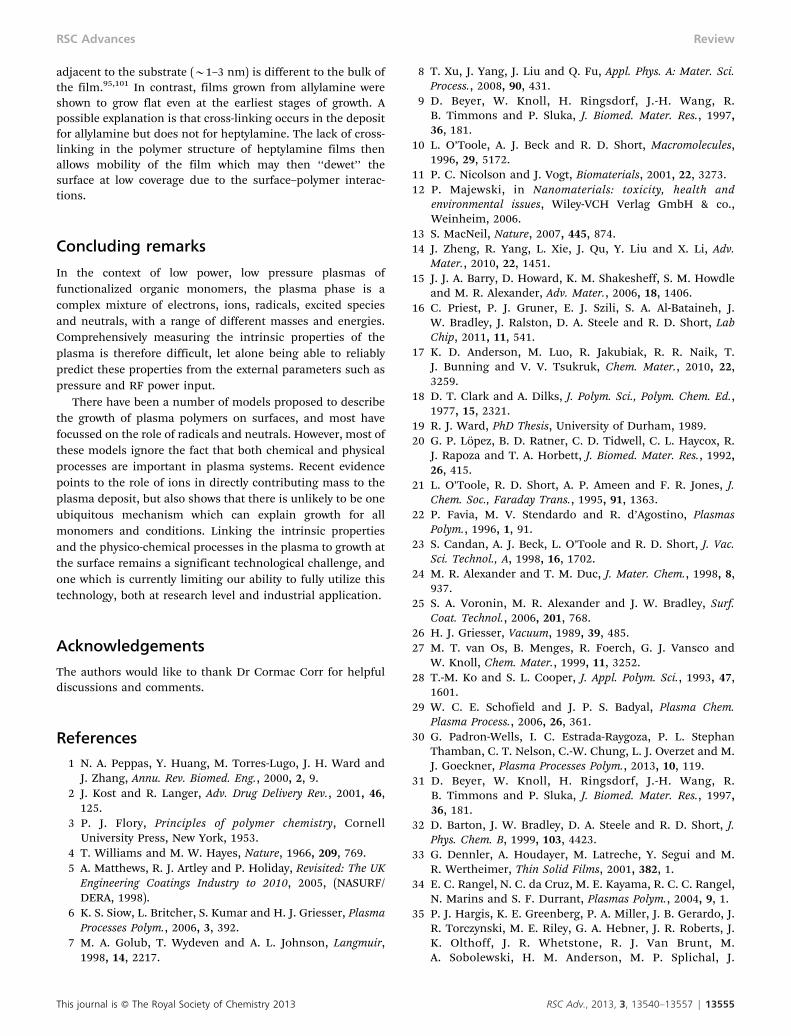
Fig. 12 shows the IR spectra of allylamine plasma polymersat different RF power input. It can clearly be seen that thebands at y2200 cm21 and y3350 cm21 become moreprominent with increasing power.98 The increase in thesebands is indicative of an increase in doubly and triply bondedgroups being formed in the plasma and depositing in the film.Based on these IR spectra, combined with deposition rateresults, Choukourov et al. proposed a mix of radical/neutraland ion deposition mechanisms. They also noted a largedecrease in deposition rate for ethanediamine compared toallylamine, which was attributed to the lack of a double bond,ruling out intact molecule–surface radical deposition.
Secondary ion mass spectroscopy (SIMS)
Secondary Ion Mass Spectrometry is a method for probing thechemical structure of surfaces.93 Heavy, high energy ions(typically gallium or gold, at y30 keV) are used to sputter thesurface which cause secondary particles, (electrons, atoms,radicals and ions) to be ejected from the surface. In staticmode, the primary ion current is kept low (,1012 ions cm22)and the ions are spread over the target region such that thesecondary ions remain relatively intact. The secondary ions arethen measured with a quadrupole mass spectrometer asdiscussed earlier, or using a Time-of-Flight (ToF) massspectrometer.
SIMS gives useful information about the chemical structureof the surface deposit. The link between the measured ionfragments and the polymer structure is strong, particularlywhen specific functionality is observed. It has been shown forHMDSO41,78 that the positive SIMS of the deposit exhibits thesame ion fragments as those measured in the plasma phase,including both monomer fragments and oligomers. Thisstrongly suggests that ions are integral to the growth of theseplasma polymer films.
Atomic force microscopy (AFM)
Atomic Force Microscopy is a high resolution 3D imagingtechnique, capable of measuring features down to less than 1nanometre.99 A cantilever with a sharp tip (tip radius , 10 nm)is brought into contact with the surface, where the forcebetween tip and the surface results in deflection of thecantilever. The cantilever is scanned over the surface, typicallyover areas of 100 mm 6 100 mm or less. Deflections of thecantilever as it scans over features on the surface are measuredby reflecting a laser off the back of the cantilever onto a fourquadrant photodiode. Usually, in order to avoid the tip hittinglarge features and being damaged, the cantilever is mountedon a piezoelectric tube and a feedback mechanism is used tomaintain a constant force between the tip and the surface.
AFM can be used to follow the deposition of plasmapolymers over time. In Fig. 13 above, the plasma polymerfilm grown from heptylamine is shown to initially grow asdiscrete islands, which then coalesce and eventually form aflat, pinhole free film after approximately 30 s.100 This result iscontrary to the often-stated view of plasma deposition thatfilms always grow as a conformal layer. It has also beenobserved by XPS that the chemistry of the film immediately
Fig. 12 IR spectra of allylamine plasma polymers at different power.(Reproduced with permission from ref. 98).
Fig. 13 AFM images (4 mm 6 4 mm) with profiles (below) showing the evolutionof a plasma deposit from heptylamine plasma. Times are 7s (left), 15s, 25s and40s. (Reproduced with permission from ref. 100.)
13554 | RSC Adv., 2013, 3, 13540–13557 This journal is � The Royal Society of Chemistry 2013
Review RSC Advances
adjacent to the substrate (y1–3 nm) is different to the bulk ofthe film.95,101 In contrast, films grown from allylamine wereshown to grow flat even at the earliest stages of growth. Apossible explanation is that cross-linking occurs in the depositfor allylamine but does not for heptylamine. The lack of cross-linking in the polymer structure of heptylamine films thenallows mobility of the film which may then ‘‘dewet’’ thesurface at low coverage due to the surface–polymer interac-tions.
Concluding remarks
In the context of low power, low pressure plasmas offunctionalized organic monomers, the plasma phase is acomplex mixture of electrons, ions, radicals, excited speciesand neutrals, with a range of different masses and energies.Comprehensively measuring the intrinsic properties of theplasma is therefore difficult, let alone being able to reliablypredict these properties from the external parameters such aspressure and RF power input.
There have been a number of models proposed to describethe growth of plasma polymers on surfaces, and most havefocussed on the role of radicals and neutrals. However, most ofthese models ignore the fact that both chemical and physicalprocesses are important in plasma systems. Recent evidencepoints to the role of ions in directly contributing mass to theplasma deposit, but also shows that there is unlikely to be oneubiquitous mechanism which can explain growth for allmonomers and conditions. Linking the intrinsic propertiesand the physico-chemical processes in the plasma to growth atthe surface remains a significant technological challenge, andone which is currently limiting our ability to fully utilize thistechnology, both at research level and industrial application.
Acknowledgements
The authors would like to thank Dr Cormac Corr for helpfuldiscussions and comments.
References
1 N. A. Peppas, Y. Huang, M. Torres-Lugo, J. H. Ward andJ. Zhang, Annu. Rev. Biomed. Eng., 2000, 2, 9.
2 J. Kost and R. Langer, Adv. Drug Delivery Rev., 2001, 46,125.
3 P. J. Flory, Principles of polymer chemistry, CornellUniversity Press, New York, 1953.
4 T. Williams and M. W. Hayes, Nature, 1966, 209, 769.5 A. Matthews, R. J. Artley and P. Holiday, Revisited: The UK
Engineering Coatings Industry to 2010, 2005, (NASURF/DERA, 1998).
6 K. S. Siow, L. Britcher, S. Kumar and H. J. Griesser, PlasmaProcesses Polym., 2006, 3, 392.
7 M. A. Golub, T. Wydeven and A. L. Johnson, Langmuir,1998, 14, 2217.
8 T. Xu, J. Yang, J. Liu and Q. Fu, Appl. Phys. A: Mater. Sci.Process., 2008, 90, 431.
9 D. Beyer, W. Knoll, H. Ringsdorf, J.-H. Wang, R.B. Timmons and P. Sluka, J. Biomed. Mater. Res., 1997,36, 181.
10 L. O’Toole, A. J. Beck and R. D. Short, Macromolecules,1996, 29, 5172.
11 P. C. Nicolson and J. Vogt, Biomaterials, 2001, 22, 3273.12 P. Majewski, in Nanomaterials: toxicity, health and
environmental issues, Wiley-VCH Verlag GmbH & co.,Weinheim, 2006.
13 S. MacNeil, Nature, 2007, 445, 874.14 J. Zheng, R. Yang, L. Xie, J. Qu, Y. Liu and X. Li, Adv.
Mater., 2010, 22, 1451.15 J. J. A. Barry, D. Howard, K. M. Shakesheff, S. M. Howdle
and M. R. Alexander, Adv. Mater., 2006, 18, 1406.16 C. Priest, P. J. Gruner, E. J. Szili, S. A. Al-Bataineh, J.
W. Bradley, J. Ralston, D. A. Steele and R. D. Short, LabChip, 2011, 11, 541.
17 K. D. Anderson, M. Luo, R. Jakubiak, R. R. Naik, T.J. Bunning and V. V. Tsukruk, Chem. Mater., 2010, 22,3259.
18 D. T. Clark and A. Dilks, J. Polym. Sci., Polym. Chem. Ed.,1977, 15, 2321.
19 R. J. Ward, PhD Thesis, University of Durham, 1989.20 G. P. Lopez, B. D. Ratner, C. D. Tidwell, C. L. Haycox, R.
J. Rapoza and T. A. Horbett, J. Biomed. Mater. Res., 1992,26, 415.
21 L. O’Toole, R. D. Short, A. P. Ameen and F. R. Jones, J.Chem. Soc., Faraday Trans., 1995, 91, 1363.
22 P. Favia, M. V. Stendardo and R. d’Agostino, PlasmasPolym., 1996, 1, 91.
23 S. Candan, A. J. Beck, L. O’Toole and R. D. Short, J. Vac.Sci. Technol., A, 1998, 16, 1702.
24 M. R. Alexander and T. M. Duc, J. Mater. Chem., 1998, 8,937.
25 S. A. Voronin, M. R. Alexander and J. W. Bradley, Surf.Coat. Technol., 2006, 201, 768.
26 H. J. Griesser, Vacuum, 1989, 39, 485.27 M. T. van Os, B. Menges, R. Foerch, G. J. Vansco and
W. Knoll, Chem. Mater., 1999, 11, 3252.28 T.-M. Ko and S. L. Cooper, J. Appl. Polym. Sci., 1993, 47,
1601.29 W. C. E. Schofield and J. P. S. Badyal, Plasma Chem.
Plasma Process., 2006, 26, 361.30 G. Padron-Wells, I. C. Estrada-Raygoza, P. L. Stephan
Thamban, C. T. Nelson, C.-W. Chung, L. J. Overzet and M.J. Goeckner, Plasma Processes Polym., 2013, 10, 119.
31 D. Beyer, W. Knoll, H. Ringsdorf, J.-H. Wang, R.B. Timmons and P. Sluka, J. Biomed. Mater. Res., 1997,36, 181.
32 D. Barton, J. W. Bradley, D. A. Steele and R. D. Short, J.Phys. Chem. B, 1999, 103, 4423.
33 G. Dennler, A. Houdayer, M. Latreche, Y. Segui and M.R. Wertheimer, Thin Solid Films, 2001, 382, 1.
34 E. C. Rangel, N. C. da Cruz, M. E. Kayama, R. C. C. Rangel,N. Marins and S. F. Durrant, Plasmas Polym., 2004, 9, 1.
35 P. J. Hargis, K. E. Greenberg, P. A. Miller, J. B. Gerardo, J.R. Torczynski, M. E. Riley, G. A. Hebner, J. R. Roberts, J.K. Olthoff, J. R. Whetstone, R. J. Van Brunt, M.A. Sobolewski, H. M. Anderson, M. P. Splichal, J.
This journal is � The Royal Society of Chemistry 2013 RSC Adv., 2013, 3, 13540–13557 | 13555
RSC Advances Review
L. Mock, P. Bletzinger, A. Garscadden, R. A. Gottscho,G. Selwyn, M. Dalvie, J. E. Heidenreich, J. W. Butterbaugh,M. L. Brake, M. L. Passow, J. Pender, A. Lujan, M. E. Elta,D. B. Graves, H. H. Sawin, M. J. Kushner, J. T. Verdeyen,R. Horwath and T. R. Turner, Rev. Sci. Instrum., 1994, 65,140.
36 M. A. Sobelewski, J. Res. Natl. Inst. Stand. Technol., 1995,100, 341.
37 D. Barton, A. G. Shard, R. D. Short and J. W. Bradley, J.Phys. Chem. B, 2005, 109, 3207.
38 A. Choukourov, H. Biederman, D. Slavinska, L. Hanley,A. Grinevich, H. Boldyryeva and A. Mackova, J. Phys. Chem.B, 2005, 109, 23086.
39 L. O’Toole, C. A. Mayhew and R. D. Short, J. Chem. Soc.,Faraday Trans., 1997, 93, 1961.
40 P. Favia, V. H. Perez-Luna, T. Boland, D. G. Castner and B.D. Ratner, Plasmas Polym., 1996, 1, 299.
41 M. R. Alexander, F. R. Jones and R. D. Short, J. Phys. Chem.B, 1997, 101, 3614.
42 E. O. Hulburt, Phys. Rev., 1931, 37, 1.43 R. A. Anthes, Atmos. Meas. Tech. Discuss., 2011, 4, 135.44 E. Kawamura, M. A. Lieberman and A. J. Lichtenberg,
Phys. Plasmas, 2006, 13, 053506.45 M. J. Druyvesteyn and F. M. Penning, Rev. Mod. Phys.,
1940, 12, 87.46 B. Chapman, Glow Discharge Processes, John Wiley and
Sons, Chichester, 1980.47 G. Bouchoux, Mass Spectrom. Rev., 2007, 26, 775.48 G. I. Font, W. L. Morgan and G. Mennenga, J. Appl. Phys.,
2002, 91, 3530.49 D. B. Haddow, R. M. France, R. D. Short, J. W. Bradley and
D. Barton, Langmuir, 2000, 16, 5654.50 S. Agarwal, G. W. W. Quax, M. C. M. van de Senden,
D. Maroudas and E. S. Aydil, J. Vac. Sci. Technol., A, 2004,22, 71.
51 D. A. Steele, R. D. Short, P. Brown and C. A. Mayhew,Plasma Processes Polym., 2011, 8, 287.
52 M. A. Lieberman and A. J. Lichtenberg, Principles ofPlasma Discharges and Materials Processing, John Wileyand Sons, Chicester, 1994.
53 H. Yasuda, Plasma Polymerization, Academic Press,Orlando, 1985.
54 A. J. Beck, S. Candan, R. D. Short, A. Goodyear and N. St.J. Braithwaite, J. Phys. Chem. B, 2001, 105, 5730.
55 J. R. Doyle, J. Appl. Phys., 1997, 82, 4763.56 S. Stoykov, C. Eggs and U. Kortshagen, J. Phys. D: Appl.
Phys., 2001, 34, 2160.57 N. Plihon, C. S. Corr and P. Chabert, Appl. Phys. Lett.,
2005, 86, 091501.58 H. M. Mott-Smith and I. Langmuir, Phys. Rev., 1926, 28,
727.59 B. M. Annaratone and N. St. J. Braithwaite, Meas. Sci.
Technol., 1991, 2, 795.60 B. M. Annaratone, G. F. Counsell, H. Kawano and J.
E. Allen, Plasma Sources Sci. Technol., 1992, 1, 232.61 F. F. Chen, in Plasma Diagnostic Techniques, ed. R. H.
Huddlestone and S. L. Leonard, Academic Press, NewYork, 1965.
62 M. Dhayal and J. W. Bradley, Surf. Coat. Technol., 2004,184, 116.
63 S. Candan, A. J. Beck, L. O’Toole, R. D. Short, A. Goodyearand N. St. J. Braithwaite, Phys. Chem. Chem. Phys., 1999, 1,3117.
64 Ch. Hollenstein, A. A. Howling, C. Courteille, D. Magni, S.M. Scholz, G. M. W. Kroesen, N. Simons, W. de Zeeuw andW. Schwarzenbach, J. Phys. D: Appl. Phys., 1998, 31, 74.
65 D. Magni, Ch. Deschenaux, Ch. Hollenstein, A. Creatoreand P. Fayet, J. Phys. D: Appl. Phys., 2001, 34, 87.
66 Ch. Deschenaux, A. Affolter, D. Magni, Ch. Hollensteinand P. Fayet, J. Phys. D: Appl. Phys., 1999, 32, 1876.
67 A. J. M. Mackus, S. B. S. Heil, E. Langereis, H. C.M. Knoops, M. C. M. van de Sanden and W. M. M. Kessels,J. Vac. Sci. Technol., A, 2010, 28, 77.
68 P. Favia, M. Creatore, F. Palumbo, V. Colaprico andR. d’Agostino, Surf. Coat. Technol., 2001, 142–144, 1.
69 P. Rossini, P. Colpo, G. Ceccone, K. D. Jandt and F. Rossi,Mater. Sci. Eng., C, 2003, 23, 353.
70 X.-M. Zhu and Y.-K. Pu, J. Phys. D: Appl. Phys., 2010, 43,403001.
71 W. L. Wiese, J. W. Brault, K. Danzmann, V. Helbig andM. Kock, Phys. Rev. A: At., Mol., Opt. Phys., 1989, 39, 2461.
72 E. C. Rangel, N. C. da Cruz, M. E. Kayama, R. C. C. Rangel,N. Marins and S. F. Durrant, Plasmas Polym., 2004, 9, 1.
73 D. L. Crintea, U. Czarnetzki, S. Iordanova, I. Koleva andD. Luggenholscher, J. Phys. D: Appl. Phys., 2009, 42,045208.
74 D. L. Pappas and J. Hopwood, J. Vac. Sci. Technol., A, 1994,12, 1576.
75 J.-P. Booth and C. Corr, Plasma Sources Sci. Technol., 2006,15, 112.
76 C. Corr, R. Boswell and R. Carman, J. Phys. D: Appl. Phys.,2011, 44, 045201.
77 D. Bohm, In The Characteristics of Electrical Discharges inMagnetic Fields, ed. A. Guthrie and R. K. Wakerling,McGraw Hill, New York and London, 1949.
78 A. Michelmore, P. M. Bryant, D. A. Steele, K. Vasilev, J.W. Bradley and R. D. Short, Langmuir, 2011, 27, 11943.
79 N. St. J. Braithwaite, J. P. Booth and G. Cunge, PlasmaSources Sci. Technol., 1996, 5, 677.
80 M. A. Sobelewski, Appl. Phys. Lett., 1998, 72, 1146.81 A. R. Westwood, Eur. Polym. J., 1971, 7, 363.82 A. R. Denaro, P. A. Owens and A. Crawshaw, Eur. Polym. J.,
1969, 5, 471.83 M. Shen and T. Bell, ACS Symp. Ser., 1979, 108, 1.84 P. N. Brookes, S. Fraser, R. D. Short, L. Hanley, E. Fuoco,
A. Roberts and S. Hutton, J. Electron Spectrosc. Relat.Phenom., 2001, 121, 281.
85 I. Haller and P. White, J. Phys. Chem., 1963, 67, 1784.86 J.-C. Ruiz, A. St-Georges-Roubillard, C. Theresy, S. Lerouge
and M. R. Wertheimer, Plasma Processes Polym., 2010, 7,737.
87 J.-C. Ruiz, P.-L. Girard-Lauriault, F. Truica-Marasescu andM. R. Wertheimer, Radiat. Phys. Chem., 2010, 79, 310.
88 F. Truica-Marasescu and M. R. Wertheimer, Macromol.Chem. Phys., 2008, 209, 1043.
89 M. J. Titus, D. Nest and D. B. Graves, Appl. Phys. Lett.,2009, 94, 171501.
90 J. Friedrich, Plasma Processes Polym., 2011, 8, 783.91 L. O’Toole, A. J. Beck, A. P. Ameen, F. R. Jones and R.
D. Short, J. Chem. Soc., Faraday Trans., 1995, 91, 3907.
13556 | RSC Adv., 2013, 3, 13540–13557 This journal is � The Royal Society of Chemistry 2013
Review RSC Advances

92 A. Michelmore, P. Gross-Kosche, S. A. Al-Bataineh, J.D. Whittle and R. D. Short, Langmuir, 2013, 29, 2595.
93 D. Briggs, Surface analysis of polymers by XPS and staticSIMS, Cambridge University Press, Cambridge, 1998.
94 G. Beamson and D. Briggs, High Resolution XPS of OrganicPolymers: The Scienta ESCA300 Database, John Wiley andSons, Chichester, 1992.
95 K. Vasilev, A. Michelmore, P. Martinek, J. Chan, V. Sah, H.J. Griesser and R. D. Short, Plasma Processes Polym., 2010,7, 824.
96 F. Truica-Marasescu and M. R. Wertheimer, PlasmaProcesses Polym., 2008, 5, 44.
97 F. Fally, I. Virlet, J. Riga and J. J. Verbist, J. Appl. Polym.Sci., 1995, 59, 1569.
98 A. Choukourov, H. Biederman, D. Slavinska, L. Hanley,A. Grinevich, H. Boldyryeva and A. Mackova, J. Phys. Chem.B, 2005, 109, 23086.
99 G. Binning, C. F. Quate and Ch. Gerber, Phys. Rev. Lett.,1986, 56, 930.
100 A. Michelmore, P. Martinek, V. Sah, R. D. Short andK. Vasilev, Plasma Processes Polym., 2011, 8, 367.
101 R. T. Chen, B. W. Muir, L. Thomsen, A. Tadich, B. C.C. Cowie, G. K. Such, A. Postma, K. M. McLean andF. Caruso, J. Phys. Chem. B, 2011, 115, 6495.
This journal is � The Royal Society of Chemistry 2013 RSC Adv., 2013, 3, 13540–13557 | 13557
RSC Advances Review


![[16]RSC Advances QDs](https://img.dokumen.tips/doc/110x75/577cc0491a28aba7118f8b29/16rsc-advances-qds.jpg)
