Embed Size (px)
Citation preview
J2X1-7677-06ENZ0(07)December 2016
Windows/Linux
FUJITSU SoftwareServerView Resource Orchestrator Cloud Edition V3.2.0
NS Option Instruction

Preface
Purpose of This Document
This manual explains the overview, setup, and operation of NS Option (*1), an optional product of FUJITSU Software ServerViewResource Orchestrator Cloud Edition (ROR CE).
*1: NS is the abbreviation of Network Service.
This manual focuses on explaining how to set up NS Option and make it available for use on systems where FUJITSU Software ServerViewResource Orchestrator Cloud Edition will be installed. Therefore, for content that is explained in FUJITSU Software ServerView ResourceOrchestrator Cloud Edition manuals, only items are listed in this manual.
Intended Readers
This manual is written for system administrators who will use Resource Orchestrator to operate the infrastructure in private cloud or datacenter environments.When using NS Option, it is assumed that readers have basic knowledge about FUJITSU Software ServerView Resource OrchestratorCloud Edition.
Structure of This Document
This manual is composed as follows:
Chapter 1 Overview
Provides an overview of NS Option.
Chapter 2 Design and Preparations
Explains how to design and prepare for NS Option installation.
Chapter 3 Setup
Explains the setup necessary for using NS Option.
Chapter 4 Operation
Explains how to operate NS Option.
Chapter 5 Maintenance
Explains the maintenance of the NS option.
Appendix A Commands
Provides an overview of the commands available in NS Option.
Appendix B Port List
Explains the ports used by NS Option.
Appendix C Pre-configuration Method for NS Appliances
Explains the preparations for performing auto-configuration for NS Option.
Web Site URLs
URLs provided as reference sources within the main text are correct as of December 2016.
Document Conventions
The notation in this manual conforms to the following conventions.
- When there is different information for the different versions of Resource Orchestrator, it is indicated as follows:
- i -
[All Editions] Sections relevant for all editions
[Cloud Edition] Sections related to Cloud Edition
[Virtual Edition] Sections related to Virtual Edition
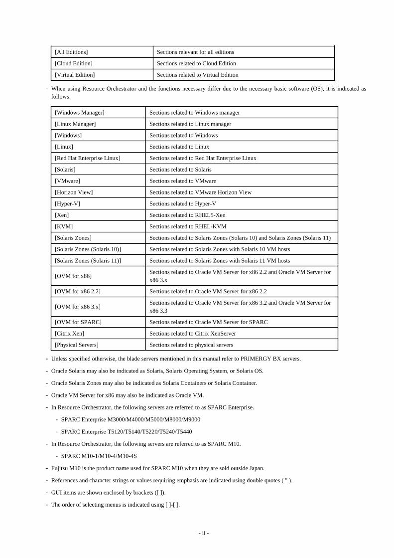
- When using Resource Orchestrator and the functions necessary differ due to the necessary basic software (OS), it is indicated asfollows:
[Windows Manager] Sections related to Windows manager
[Linux Manager] Sections related to Linux manager
[Windows] Sections related to Windows
[Linux] Sections related to Linux
[Red Hat Enterprise Linux] Sections related to Red Hat Enterprise Linux
[Solaris] Sections related to Solaris
[VMware] Sections related to VMware
[Horizon View] Sections related to VMware Horizon View
[Hyper-V] Sections related to Hyper-V
[Xen] Sections related to RHEL5-Xen
[KVM] Sections related to RHEL-KVM
[Solaris Zones] Sections related to Solaris Zones (Solaris 10) and Solaris Zones (Solaris 11)
[Solaris Zones (Solaris 10)] Sections related to Solaris Zones with Solaris 10 VM hosts
[Solaris Zones (Solaris 11)] Sections related to Solaris Zones with Solaris 11 VM hosts
[OVM for x86]Sections related to Oracle VM Server for x86 2.2 and Oracle VM Server forx86 3.x
[OVM for x86 2.2] Sections related to Oracle VM Server for x86 2.2
[OVM for x86 3.x]Sections related to Oracle VM Server for x86 3.2 and Oracle VM Server forx86 3.3
[OVM for SPARC] Sections related to Oracle VM Server for SPARC
[Citrix Xen] Sections related to Citrix XenServer
[Physical Servers] Sections related to physical servers
- Unless specified otherwise, the blade servers mentioned in this manual refer to PRIMERGY BX servers.
- Oracle Solaris may also be indicated as Solaris, Solaris Operating System, or Solaris OS.
- Oracle Solaris Zones may also be indicated as Solaris Containers or Solaris Container.
- Oracle VM Server for x86 may also be indicated as Oracle VM.
- In Resource Orchestrator, the following servers are referred to as SPARC Enterprise.
- SPARC Enterprise M3000/M4000/M5000/M8000/M9000
- SPARC Enterprise T5120/T5140/T5220/T5240/T5440
- In Resource Orchestrator, the following servers are referred to as SPARC M10.
- SPARC M10-1/M10-4/M10-4S
- Fujitsu M10 is the product name used for SPARC M10 when they are sold outside Japan.
- References and character strings or values requiring emphasis are indicated using double quotes ( " ).
- GUI items are shown enclosed by brackets ([ ]).
- The order of selecting menus is indicated using [ ]-[ ].
- ii -
- Text to be entered by the user is indicated using bold text.
- Variables are indicated using italic text and underscores.
- The ellipses ("...") in menu names, indicating settings and operation window startup, are not shown.
- The ">" used in Windows is included in usage examples. When using Linux, read ">" as meaning "#".
- When using Resource Orchestrator on Windows 8 and Windows Server 2012, please note the following.When OS operations are explained in this manual, the examples assume OSs up to Windows 7 and Windows Server 2008. When usingResource Orchestrator on Windows 8 or Windows Server 2012, take explanations regarding the [Start] menu as indicating the [Apps]screen.The [Apps] screen can be displayed by right-clicking on the [Start] screen and then right-clicking [All apps].
- When using Resource Orchestrator on Windows 8.1 and Windows Server 2012 R2, please note the following.When OS operations are explained in this manual, the examples assume OSs up to Windows 7 and Windows Server 2008. When usingResource Orchestrator on Windows 8.1 or Windows Server 2012 R2, take explanations regarding the [Start] menu as indicating the[Apps] screen.The [Apps] screen can be displayed by swiping the [Start] screen from bottom to top, or clicking the downward facing arrow on thelower-left of the [Start] screen.
Menus in the ROR console
Operations on the ROR console can be performed using either the menu bar or pop-up menus.
By convention, procedures described in this manual only refer to pop-up menus.
Regarding Installation Folder Paths
The installation folder path may be given as C:\Fujitsu\ROR in this manual.
Replace it as shown below.
[Virtual Edition]
- When using Windows 64-bit (x64)
C:\Program Files (x86)\Resource Orchestrator
- When using Windows 32-bit (x86)
C:\Program Files\Resource Orchestrator
[Cloud Edition]
C:\Program Files (x86)\Resource Orchestrator
Command Examples
The paths used in command examples may be abbreviated. When using commands, execute them using the paths in the "Name" columnin the "Reference Guide (Command) VE" and the "Reference Guide (Command/XML) CE".
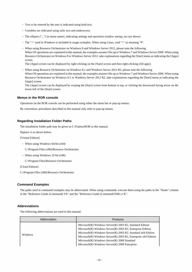
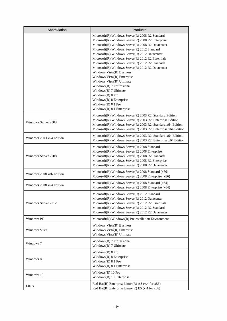
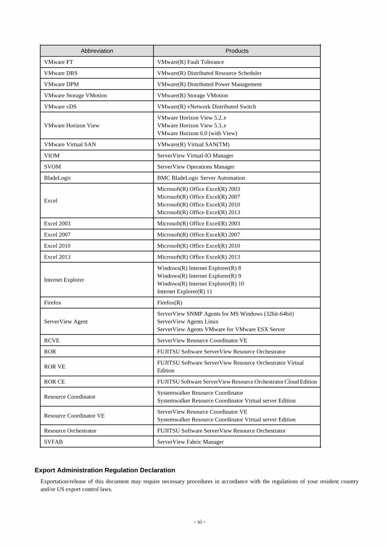
Abbreviations
The following abbreviations are used in this manual:
Abbreviation Products
Windows
Microsoft(R) Windows Server(R) 2003 R2, Standard EditionMicrosoft(R) Windows Server(R) 2003 R2, Enterprise EditionMicrosoft(R) Windows Server(R) 2003 R2, Standard x64 EditionMicrosoft(R) Windows Server(R) 2003 R2, Enterprise x64 EditionMicrosoft(R) Windows Server(R) 2008 StandardMicrosoft(R) Windows Server(R) 2008 Enterprise
- iii -
Abbreviation Products
Microsoft(R) Windows Server(R) 2008 R2 StandardMicrosoft(R) Windows Server(R) 2008 R2 EnterpriseMicrosoft(R) Windows Server(R) 2008 R2 DatacenterMicrosoft(R) Windows Server(R) 2012 StandardMicrosoft(R) Windows Server(R) 2012 DatacenterMicrosoft(R) Windows Server(R) 2012 R2 EssentialsMicrosoft(R) Windows Server(R) 2012 R2 StandardMicrosoft(R) Windows Server(R) 2012 R2 DatacenterWindows Vista(R) BusinessWindows Vista(R) EnterpriseWindows Vista(R) UltimateWindows(R) 7 ProfessionalWindows(R) 7 UltimateWindows(R) 8 ProWindows(R) 8 EnterpriseWindows(R) 8.1 ProWindows(R) 8.1 Enterprise
Windows Server 2003
Microsoft(R) Windows Server(R) 2003 R2, Standard EditionMicrosoft(R) Windows Server(R) 2003 R2, Enterprise EditionMicrosoft(R) Windows Server(R) 2003 R2, Standard x64 EditionMicrosoft(R) Windows Server(R) 2003 R2, Enterprise x64 Edition
Windows 2003 x64 EditionMicrosoft(R) Windows Server(R) 2003 R2, Standard x64 EditionMicrosoft(R) Windows Server(R) 2003 R2, Enterprise x64 Edition
Windows Server 2008
Microsoft(R) Windows Server(R) 2008 StandardMicrosoft(R) Windows Server(R) 2008 EnterpriseMicrosoft(R) Windows Server(R) 2008 R2 StandardMicrosoft(R) Windows Server(R) 2008 R2 EnterpriseMicrosoft(R) Windows Server(R) 2008 R2 Datacenter
Windows 2008 x86 EditionMicrosoft(R) Windows Server(R) 2008 Standard (x86)Microsoft(R) Windows Server(R) 2008 Enterprise (x86)
Windows 2008 x64 EditionMicrosoft(R) Windows Server(R) 2008 Standard (x64)Microsoft(R) Windows Server(R) 2008 Enterprise (x64)
Windows Server 2012
Microsoft(R) Windows Server(R) 2012 StandardMicrosoft(R) Windows Server(R) 2012 DatacenterMicrosoft(R) Windows Server(R) 2012 R2 EssentialsMicrosoft(R) Windows Server(R) 2012 R2 StandardMicrosoft(R) Windows Server(R) 2012 R2 Datacenter
Windows PE Microsoft(R) Windows(R) Preinstallation Environment
Windows VistaWindows Vista(R) BusinessWindows Vista(R) EnterpriseWindows Vista(R) Ultimate
Windows 7Windows(R) 7 ProfessionalWindows(R) 7 Ultimate
Windows 8
Windows(R) 8 ProWindows(R) 8 EnterpriseWindows(R) 8.1 ProWindows(R) 8.1 Enterprise
Windows 10Windows(R) 10 ProWindows(R) 10 Enterprise
LinuxRed Hat(R) Enterprise Linux(R) AS (v.4 for x86)Red Hat(R) Enterprise Linux(R) ES (v.4 for x86)
- iv -
Abbreviation Products
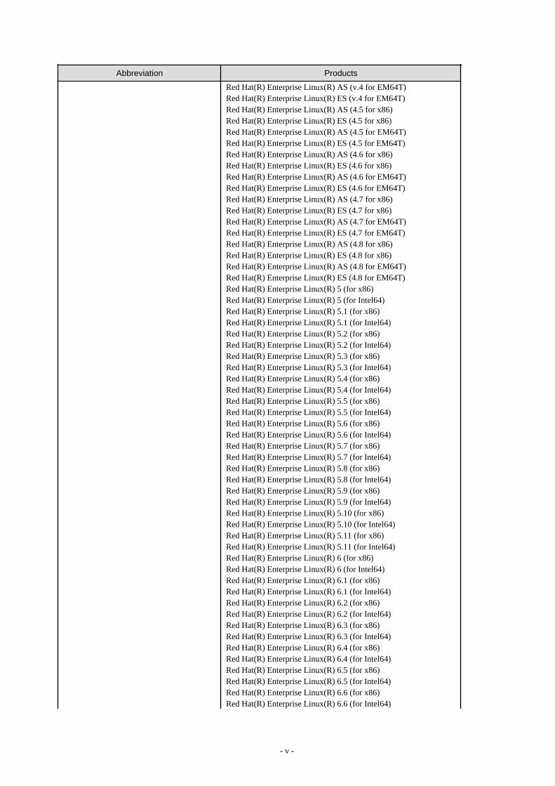
Red Hat(R) Enterprise Linux(R) AS (v.4 for EM64T)Red Hat(R) Enterprise Linux(R) ES (v.4 for EM64T)Red Hat(R) Enterprise Linux(R) AS (4.5 for x86)Red Hat(R) Enterprise Linux(R) ES (4.5 for x86)Red Hat(R) Enterprise Linux(R) AS (4.5 for EM64T)Red Hat(R) Enterprise Linux(R) ES (4.5 for EM64T)Red Hat(R) Enterprise Linux(R) AS (4.6 for x86)Red Hat(R) Enterprise Linux(R) ES (4.6 for x86)Red Hat(R) Enterprise Linux(R) AS (4.6 for EM64T)Red Hat(R) Enterprise Linux(R) ES (4.6 for EM64T)Red Hat(R) Enterprise Linux(R) AS (4.7 for x86)Red Hat(R) Enterprise Linux(R) ES (4.7 for x86)Red Hat(R) Enterprise Linux(R) AS (4.7 for EM64T)Red Hat(R) Enterprise Linux(R) ES (4.7 for EM64T)Red Hat(R) Enterprise Linux(R) AS (4.8 for x86)Red Hat(R) Enterprise Linux(R) ES (4.8 for x86)Red Hat(R) Enterprise Linux(R) AS (4.8 for EM64T)Red Hat(R) Enterprise Linux(R) ES (4.8 for EM64T)Red Hat(R) Enterprise Linux(R) 5 (for x86)Red Hat(R) Enterprise Linux(R) 5 (for Intel64)Red Hat(R) Enterprise Linux(R) 5.1 (for x86)Red Hat(R) Enterprise Linux(R) 5.1 (for Intel64)Red Hat(R) Enterprise Linux(R) 5.2 (for x86)Red Hat(R) Enterprise Linux(R) 5.2 (for Intel64)Red Hat(R) Enterprise Linux(R) 5.3 (for x86)Red Hat(R) Enterprise Linux(R) 5.3 (for Intel64)Red Hat(R) Enterprise Linux(R) 5.4 (for x86)Red Hat(R) Enterprise Linux(R) 5.4 (for Intel64)Red Hat(R) Enterprise Linux(R) 5.5 (for x86)Red Hat(R) Enterprise Linux(R) 5.5 (for Intel64)Red Hat(R) Enterprise Linux(R) 5.6 (for x86)Red Hat(R) Enterprise Linux(R) 5.6 (for Intel64)Red Hat(R) Enterprise Linux(R) 5.7 (for x86)Red Hat(R) Enterprise Linux(R) 5.7 (for Intel64)Red Hat(R) Enterprise Linux(R) 5.8 (for x86)Red Hat(R) Enterprise Linux(R) 5.8 (for Intel64)Red Hat(R) Enterprise Linux(R) 5.9 (for x86)Red Hat(R) Enterprise Linux(R) 5.9 (for Intel64)Red Hat(R) Enterprise Linux(R) 5.10 (for x86)Red Hat(R) Enterprise Linux(R) 5.10 (for Intel64)Red Hat(R) Enterprise Linux(R) 5.11 (for x86)Red Hat(R) Enterprise Linux(R) 5.11 (for Intel64)Red Hat(R) Enterprise Linux(R) 6 (for x86)Red Hat(R) Enterprise Linux(R) 6 (for Intel64)Red Hat(R) Enterprise Linux(R) 6.1 (for x86)Red Hat(R) Enterprise Linux(R) 6.1 (for Intel64)Red Hat(R) Enterprise Linux(R) 6.2 (for x86)Red Hat(R) Enterprise Linux(R) 6.2 (for Intel64)Red Hat(R) Enterprise Linux(R) 6.3 (for x86)Red Hat(R) Enterprise Linux(R) 6.3 (for Intel64)Red Hat(R) Enterprise Linux(R) 6.4 (for x86)Red Hat(R) Enterprise Linux(R) 6.4 (for Intel64)Red Hat(R) Enterprise Linux(R) 6.5 (for x86)Red Hat(R) Enterprise Linux(R) 6.5 (for Intel64)Red Hat(R) Enterprise Linux(R) 6.6 (for x86)Red Hat(R) Enterprise Linux(R) 6.6 (for Intel64)
- v -

Abbreviation Products
Red Hat(R) Enterprise Linux(R) 6.7 (for x86)Red Hat(R) Enterprise Linux(R) 6.7 (for Intel64)Red Hat(R) Enterprise Linux(R) 6.8 (for x86)Red Hat(R) Enterprise Linux(R) 6.8 (for Intel64)Red Hat(R) Enterprise Linux(R) 7.0 (for Intel64)SUSE(R) Linux Enterprise Server 10 Service Pack 2 for x86SUSE(R) Linux Enterprise Server 10 Service Pack 2 for EM64TSUSE(R) Linux Enterprise Server 10 Service Pack 3 for x86SUSE(R) Linux Enterprise Server 10 Service Pack 3 for EM64TSUSE(R) Linux Enterprise Server 11 for x86SUSE(R) Linux Enterprise Server 11 for EM64TSUSE(R) Linux Enterprise Server 11 Service Pack 1 for x86SUSE(R) Linux Enterprise Server 11 Service Pack 1 for EM64TOracle Enterprise Linux Release 6.7 for x86 (32bit)Oracle Enterprise Linux Release 6.7 for 86_64 (64bit)Oracle Enterprise Linux Release 7.2 for x86 (32bit)Oracle Enterprise Linux Release 7.2 for x86_64 (64bit)
Red Hat Enterprise Linux
Red Hat(R) Enterprise Linux(R) AS (v.4 for x86)Red Hat(R) Enterprise Linux(R) ES (v.4 for x86)Red Hat(R) Enterprise Linux(R) AS (v.4 for EM64T)Red Hat(R) Enterprise Linux(R) ES (v.4 for EM64T)Red Hat(R) Enterprise Linux(R) AS (4.5 for x86)Red Hat(R) Enterprise Linux(R) ES (4.5 for x86)Red Hat(R) Enterprise Linux(R) AS (4.5 for EM64T)Red Hat(R) Enterprise Linux(R) ES (4.5 for EM64T)Red Hat(R) Enterprise Linux(R) AS (4.6 for x86)Red Hat(R) Enterprise Linux(R) ES (4.6 for x86)Red Hat(R) Enterprise Linux(R) AS (4.6 for EM64T)Red Hat(R) Enterprise Linux(R) ES (4.6 for EM64T)Red Hat(R) Enterprise Linux(R) AS (4.7 for x86)Red Hat(R) Enterprise Linux(R) ES (4.7 for x86)Red Hat(R) Enterprise Linux(R) AS (4.7 for EM64T)Red Hat(R) Enterprise Linux(R) ES (4.7 for EM64T)Red Hat(R) Enterprise Linux(R) AS (4.8 for x86)Red Hat(R) Enterprise Linux(R) ES (4.8 for x86)Red Hat(R) Enterprise Linux(R) AS (4.8 for EM64T)Red Hat(R) Enterprise Linux(R) ES (4.8 for EM64T)Red Hat(R) Enterprise Linux(R) 5 (for x86)Red Hat(R) Enterprise Linux(R) 5 (for Intel64)Red Hat(R) Enterprise Linux(R) 5.1 (for x86)Red Hat(R) Enterprise Linux(R) 5.1 (for Intel64)Red Hat(R) Enterprise Linux(R) 5.2 (for x86)Red Hat(R) Enterprise Linux(R) 5.2 (for Intel64)Red Hat(R) Enterprise Linux(R) 5.3 (for x86)Red Hat(R) Enterprise Linux(R) 5.3 (for Intel64)Red Hat(R) Enterprise Linux(R) 5.4 (for x86)Red Hat(R) Enterprise Linux(R) 5.4 (for Intel64)Red Hat(R) Enterprise Linux(R) 5.5 (for x86)Red Hat(R) Enterprise Linux(R) 5.5 (for Intel64)Red Hat(R) Enterprise Linux(R) 5.6 (for x86)Red Hat(R) Enterprise Linux(R) 5.6 (for Intel64)Red Hat(R) Enterprise Linux(R) 5.7 (for x86)Red Hat(R) Enterprise Linux(R) 5.7 (for Intel64)Red Hat(R) Enterprise Linux(R) 5.8 (for x86)Red Hat(R) Enterprise Linux(R) 5.8 (for Intel64)Red Hat(R) Enterprise Linux(R) 5.9 (for x86)
- vi -
Abbreviation Products
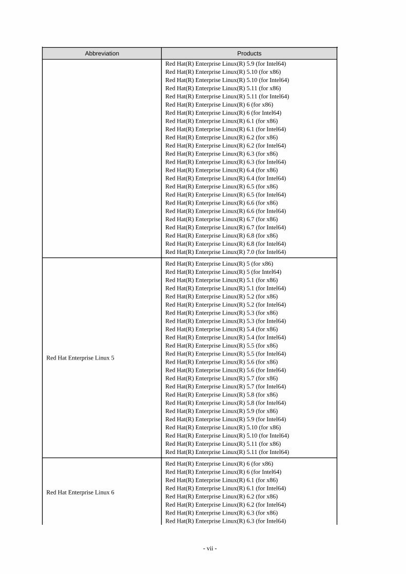
Red Hat(R) Enterprise Linux(R) 5.9 (for Intel64)Red Hat(R) Enterprise Linux(R) 5.10 (for x86)Red Hat(R) Enterprise Linux(R) 5.10 (for Intel64)Red Hat(R) Enterprise Linux(R) 5.11 (for x86)Red Hat(R) Enterprise Linux(R) 5.11 (for Intel64)Red Hat(R) Enterprise Linux(R) 6 (for x86)Red Hat(R) Enterprise Linux(R) 6 (for Intel64)Red Hat(R) Enterprise Linux(R) 6.1 (for x86)Red Hat(R) Enterprise Linux(R) 6.1 (for Intel64)Red Hat(R) Enterprise Linux(R) 6.2 (for x86)Red Hat(R) Enterprise Linux(R) 6.2 (for Intel64)Red Hat(R) Enterprise Linux(R) 6.3 (for x86)Red Hat(R) Enterprise Linux(R) 6.3 (for Intel64)Red Hat(R) Enterprise Linux(R) 6.4 (for x86)Red Hat(R) Enterprise Linux(R) 6.4 (for Intel64)Red Hat(R) Enterprise Linux(R) 6.5 (for x86)Red Hat(R) Enterprise Linux(R) 6.5 (for Intel64)Red Hat(R) Enterprise Linux(R) 6.6 (for x86)Red Hat(R) Enterprise Linux(R) 6.6 (for Intel64)Red Hat(R) Enterprise Linux(R) 6.7 (for x86)Red Hat(R) Enterprise Linux(R) 6.7 (for Intel64)Red Hat(R) Enterprise Linux(R) 6.8 (for x86)Red Hat(R) Enterprise Linux(R) 6.8 (for Intel64)Red Hat(R) Enterprise Linux(R) 7.0 (for Intel64)
Red Hat Enterprise Linux 5
Red Hat(R) Enterprise Linux(R) 5 (for x86)Red Hat(R) Enterprise Linux(R) 5 (for Intel64)Red Hat(R) Enterprise Linux(R) 5.1 (for x86)Red Hat(R) Enterprise Linux(R) 5.1 (for Intel64)Red Hat(R) Enterprise Linux(R) 5.2 (for x86)Red Hat(R) Enterprise Linux(R) 5.2 (for Intel64)Red Hat(R) Enterprise Linux(R) 5.3 (for x86)Red Hat(R) Enterprise Linux(R) 5.3 (for Intel64)Red Hat(R) Enterprise Linux(R) 5.4 (for x86)Red Hat(R) Enterprise Linux(R) 5.4 (for Intel64)Red Hat(R) Enterprise Linux(R) 5.5 (for x86)Red Hat(R) Enterprise Linux(R) 5.5 (for Intel64)Red Hat(R) Enterprise Linux(R) 5.6 (for x86)Red Hat(R) Enterprise Linux(R) 5.6 (for Intel64)Red Hat(R) Enterprise Linux(R) 5.7 (for x86)Red Hat(R) Enterprise Linux(R) 5.7 (for Intel64)Red Hat(R) Enterprise Linux(R) 5.8 (for x86)Red Hat(R) Enterprise Linux(R) 5.8 (for Intel64)Red Hat(R) Enterprise Linux(R) 5.9 (for x86)Red Hat(R) Enterprise Linux(R) 5.9 (for Intel64)Red Hat(R) Enterprise Linux(R) 5.10 (for x86)Red Hat(R) Enterprise Linux(R) 5.10 (for Intel64)Red Hat(R) Enterprise Linux(R) 5.11 (for x86)Red Hat(R) Enterprise Linux(R) 5.11 (for Intel64)
Red Hat Enterprise Linux 6
Red Hat(R) Enterprise Linux(R) 6 (for x86)Red Hat(R) Enterprise Linux(R) 6 (for Intel64)Red Hat(R) Enterprise Linux(R) 6.1 (for x86)Red Hat(R) Enterprise Linux(R) 6.1 (for Intel64)Red Hat(R) Enterprise Linux(R) 6.2 (for x86)Red Hat(R) Enterprise Linux(R) 6.2 (for Intel64)Red Hat(R) Enterprise Linux(R) 6.3 (for x86)Red Hat(R) Enterprise Linux(R) 6.3 (for Intel64)
- vii -
Abbreviation Products
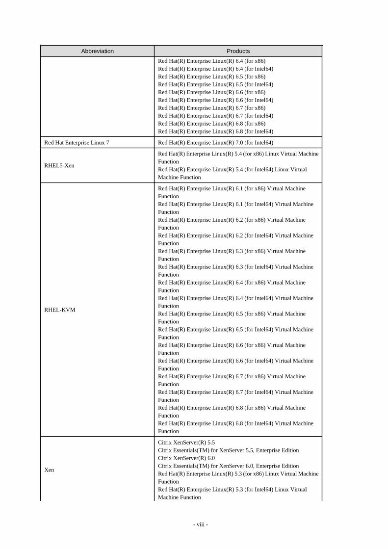
Red Hat(R) Enterprise Linux(R) 6.4 (for x86)Red Hat(R) Enterprise Linux(R) 6.4 (for Intel64)Red Hat(R) Enterprise Linux(R) 6.5 (for x86)Red Hat(R) Enterprise Linux(R) 6.5 (for Intel64)Red Hat(R) Enterprise Linux(R) 6.6 (for x86)Red Hat(R) Enterprise Linux(R) 6.6 (for Intel64)Red Hat(R) Enterprise Linux(R) 6.7 (for x86)Red Hat(R) Enterprise Linux(R) 6.7 (for Intel64)Red Hat(R) Enterprise Linux(R) 6.8 (for x86)Red Hat(R) Enterprise Linux(R) 6.8 (for Intel64)
Red Hat Enterprise Linux 7 Red Hat(R) Enterprise Linux(R) 7.0 (for Intel64)
RHEL5-Xen
Red Hat(R) Enterprise Linux(R) 5.4 (for x86) Linux Virtual MachineFunctionRed Hat(R) Enterprise Linux(R) 5.4 (for Intel64) Linux VirtualMachine Function
RHEL-KVM
Red Hat(R) Enterprise Linux(R) 6.1 (for x86) Virtual MachineFunctionRed Hat(R) Enterprise Linux(R) 6.1 (for Intel64) Virtual MachineFunctionRed Hat(R) Enterprise Linux(R) 6.2 (for x86) Virtual MachineFunctionRed Hat(R) Enterprise Linux(R) 6.2 (for Intel64) Virtual MachineFunctionRed Hat(R) Enterprise Linux(R) 6.3 (for x86) Virtual MachineFunctionRed Hat(R) Enterprise Linux(R) 6.3 (for Intel64) Virtual MachineFunctionRed Hat(R) Enterprise Linux(R) 6.4 (for x86) Virtual MachineFunctionRed Hat(R) Enterprise Linux(R) 6.4 (for Intel64) Virtual MachineFunctionRed Hat(R) Enterprise Linux(R) 6.5 (for x86) Virtual MachineFunctionRed Hat(R) Enterprise Linux(R) 6.5 (for Intel64) Virtual MachineFunctionRed Hat(R) Enterprise Linux(R) 6.6 (for x86) Virtual MachineFunctionRed Hat(R) Enterprise Linux(R) 6.6 (for Intel64) Virtual MachineFunctionRed Hat(R) Enterprise Linux(R) 6.7 (for x86) Virtual MachineFunctionRed Hat(R) Enterprise Linux(R) 6.7 (for Intel64) Virtual MachineFunctionRed Hat(R) Enterprise Linux(R) 6.8 (for x86) Virtual MachineFunctionRed Hat(R) Enterprise Linux(R) 6.8 (for Intel64) Virtual MachineFunction
Xen
Citrix XenServer(R) 5.5Citrix Essentials(TM) for XenServer 5.5, Enterprise EditionCitrix XenServer(R) 6.0Citrix Essentials(TM) for XenServer 6.0, Enterprise EditionRed Hat(R) Enterprise Linux(R) 5.3 (for x86) Linux Virtual MachineFunctionRed Hat(R) Enterprise Linux(R) 5.3 (for Intel64) Linux VirtualMachine Function
- viii -

Abbreviation Products
Red Hat(R) Enterprise Linux(R) 5.4 (for x86) Linux Virtual MachineFunctionRed Hat(R) Enterprise Linux(R) 5.4 (for Intel64) Linux VirtualMachine FunctionRed Hat(R) Enterprise Linux(R) 5.5 (for x86) Linux Virtual MachineFunctionRed Hat(R) Enterprise Linux(R) 5.5 (for Intel64) Linux VirtualMachine FunctionRed Hat(R) Enterprise Linux(R) 5.6 (for x86) Linux Virtual MachineFunctionRed Hat(R) Enterprise Linux(R) 5.6 (for Intel64) Linux VirtualMachine FunctionRed Hat(R) Enterprise Linux(R) 5.7 (for x86) Linux Virtual MachineFunctionRed Hat(R) Enterprise Linux(R) 5.7 (for Intel64) Linux VirtualMachine FunctionRed Hat(R) Enterprise Linux(R) 5.8 (for x86) Linux Virtual MachineFunctionRed Hat(R) Enterprise Linux(R) 5.8 (for Intel64) Linux VirtualMachine FunctionRed Hat(R) Enterprise Linux(R) 5.9 (for x86) Linux Virtual MachineFunctionRed Hat(R) Enterprise Linux(R) 5.9 (for Intel64) Linux VirtualMachine FunctionRed Hat(R) Enterprise Linux(R) 5.10 (for x86) Linux VirtualMachine FunctionRed Hat(R) Enterprise Linux(R) 5.10 (for Intel64) Linux VirtualMachine FunctionRed Hat(R) Enterprise Linux(R) 5.11 (for x86) Linux VirtualMachine FunctionRed Hat(R) Enterprise Linux(R) 5.11 (for Intel64) Linux VirtualMachine Function
XenServer 6Citrix XenServer(R) 6.0Citrix Essentials(TM) for XenServer 6.0, Enterprise Edition
DOS Microsoft(R) MS-DOS(R) operating system, DR DOS(R)
SUSE Linux Enterprise Server
SUSE(R) Linux Enterprise Server 10 Service Pack 2 for x86SUSE(R) Linux Enterprise Server 10 Service Pack 2 for EM64TSUSE(R) Linux Enterprise Server 10 Service Pack 3 for x86SUSE(R) Linux Enterprise Server 10 Service Pack 3 for EM64TSUSE(R) Linux Enterprise Server 11 for x86SUSE(R) Linux Enterprise Server 11 for EM64TSUSE(R) Linux Enterprise Server 11 Service Pack 1 for x86SUSE(R) Linux Enterprise Server 11 Service Pack 1 for EM64T
Oracle Enterprise Linux
Oracle Enterprise Linux Release 6.7 for x86 (32bit)Oracle Enterprise Linux Release 6.7 for 86_64 (64bit)Oracle Enterprise Linux Release 7.2 for x86 (32bit)Oracle Enterprise Linux Release 7.2 for x86_64 (64bit)
Solaris
Oracle Solaris 10 05/09 (Update7)Oracle Solaris 11 11/11Oracle Solaris 11.1Oracle Solaris 11.2
OVM for x86 2.2 Oracle(R) VM Server for x86 2.2
OVM for x86 3.x OVM for x86 3.2 Oracle VM Server for x86 v3.2.x
- ix -
Abbreviation Products
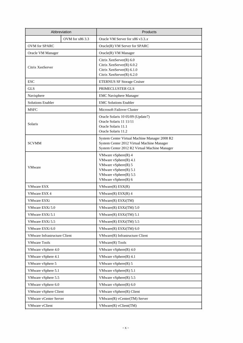
OVM for x86 3.3 Oracle VM Server for x86 v3.3.x
OVM for SPARC Oracle(R) VM Server for SPARC
Oracle VM Manager Oracle(R) VM Manager
Citrix XenServer
Citrix XenServer(R) 6.0Citrix XenServer(R) 6.0.2Citrix XenServer(R) 6.1.0Citrix XenServer(R) 6.2.0
ESC ETERNUS SF Storage Cruiser
GLS PRIMECLUSTER GLS
Navisphere EMC Navisphere Manager
Solutions Enabler EMC Solutions Enabler
MSFC Microsoft Failover Cluster
Solaris
Oracle Solaris 10 05/09 (Update7)Oracle Solaris 11 11/11Oracle Solaris 11.1Oracle Solaris 11.2
SCVMMSystem Center Virtual Machine Manager 2008 R2System Center 2012 Virtual Machine ManagerSystem Center 2012 R2 Virtual Machine Manager
VMware
VMware vSphere(R) 4VMware vSphere(R) 4.1VMware vSphere(R) 5VMware vSphere(R) 5.1VMware vSphere(R) 5.5VMware vSphere(R) 6
VMware ESX VMware(R) ESX(R)
VMware ESX 4 VMware(R) ESX(R) 4
VMware ESXi VMware(R) ESXi(TM)
VMware ESXi 5.0 VMware(R) ESXi(TM) 5.0
VMware ESXi 5.1 VMware(R) ESXi(TM) 5.1
VMware ESXi 5.5 VMware(R) ESXi(TM) 5.5
VMware ESXi 6.0 VMware(R) ESXi(TM) 6.0
VMware Infrastructure Client VMware(R) Infrastructure Client
VMware Tools VMware(R) Tools
VMware vSphere 4.0 VMware vSphere(R) 4.0
VMware vSphere 4.1 VMware vSphere(R) 4.1
VMware vSphere 5 VMware vSphere(R) 5
VMware vSphere 5.1 VMware vSphere(R) 5.1
VMware vSphere 5.5 VMware vSphere(R) 5.5
VMware vSphere 6.0 VMware vSphere(R) 6.0
VMware vSphere Client VMware vSphere(R) Client
VMware vCenter Server VMware(R) vCenter(TM) Server
VMware vClient VMware(R) vClient(TM)
- x -
Abbreviation Products
VMware FT VMware(R) Fault Tolerance
VMware DRS VMware(R) Distributed Resource Scheduler
VMware DPM VMware(R) Distributed Power Management
VMware Storage VMotion VMware(R) Storage VMotion
VMware vDS VMware(R) vNetwork Distributed Switch
VMware Horizon ViewVMware Horizon View 5.2.xVMware Horizon View 5.3.xVMware Horizon 6.0 (with View)
VMware Virtual SAN VMware(R) Virtual SAN(TM)
VIOM ServerView Virtual-IO Manager
SVOM ServerView Operations Manager
BladeLogic BMC BladeLogic Server Automation
Excel
Microsoft(R) Office Excel(R) 2003Microsoft(R) Office Excel(R) 2007Microsoft(R) Office Excel(R) 2010Microsoft(R) Office Excel(R) 2013
Excel 2003 Microsoft(R) Office Excel(R) 2003
Excel 2007 Microsoft(R) Office Excel(R) 2007
Excel 2010 Microsoft(R) Office Excel(R) 2010
Excel 2013 Microsoft(R) Office Excel(R) 2013
Internet Explorer
Windows(R) Internet Explorer(R) 8Windows(R) Internet Explorer(R) 9Windows(R) Internet Explorer(R) 10Internet Explorer(R) 11
Firefox Firefox(R)
ServerView AgentServerView SNMP Agents for MS Windows (32bit-64bit)ServerView Agents LinuxServerView Agents VMware for VMware ESX Server
RCVE ServerView Resource Coordinator VE
ROR FUJITSU Software ServerView Resource Orchestrator
ROR VEFUJITSU Software ServerView Resource Orchestrator VirtualEdition
ROR CE FUJITSU Software ServerView Resource Orchestrator Cloud Edition
Resource CoordinatorSystemwalker Resource CoordinatorSystemwalker Resource Coordinator Virtual server Edition
Resource Coordinator VEServerView Resource Coordinator VESystemwalker Resource Coordinator Virtual server Edition
Resource Orchestrator FUJITSU Software ServerView Resource Orchestrator
SVFAB ServerView Fabric Manager
Export Administration Regulation Declaration
Exportation/release of this document may require necessary procedures in accordance with the regulations of your resident countryand/or US export control laws.
- xi -
Trademark Information
- BMC, BMC Software, and the BMC Software logo are the exclusive properties of BMC Software, Inc., are registered with the U.S.Patent and Trademark Office, and may be registered or pending registration in other countries.
- Citrix(R), Citrix XenServer(R), Citrix Essentials(TM), and Citrix StorageLink(TM) are trademarks of Citrix Systems, Inc. and/or oneof its subsidiaries, and may be registered in the United States Patent and Trademark Office and in other countries.
- EMC, EMC2, CLARiiON, Symmetrix, and Navisphere are trademarks or registered trademarks of EMC Corporation.
- HP is a registered trademark of Hewlett-Packard Company.
- Linux is a trademark or registered trademark of Linus Torvalds in the United States and other countries.
- Microsoft, Windows, MS-DOS, Windows Server, Windows Vista, Excel, Active Directory, and Internet Explorer are either registeredtrademarks or trademarks of Microsoft Corporation in the United States and other countries.
- Firefox is a trademark or registered trademark of the Mozilla Foundation in the United States and other countries.
- NetApp is a registered trademark of Network Appliance, Inc. in the US and other countries. Data ONTAP, Network Appliance, andSnapshot are trademarks of Network Appliance, Inc. in the US and other countries.
- Oracle and Java are registered trademarks of Oracle and/or its affiliates in the United States and other countries.
- Oracle is a registered trademark of Oracle Corporation and/or its affiliates.
- Red Hat, RPM and all Red Hat-based trademarks and logos are trademarks or registered trademarks of Red Hat, Inc. in the UnitedStates and other countries.
- SUSE is a registered trademark of SUSE LINUX AG, a Novell business.
- VMware, the VMware "boxes" logo and design, Virtual SMP, and VMotion are registered trademarks or trademarks of VMware, Inc.in the United States and/or other jurisdictions.
- ServerView and Systemwalker are registered trademarks of FUJITSU LIMITED.
- All other brand and product names are trademarks or registered trademarks of their respective owners.
Notices
- The contents of this manual shall not be reproduced without express written permission from FUJITSU LIMITED.
- The contents of this manual are subject to change without notice.
Revision History
Month/Year Issued, Edition Manual Code
July 2012, First Edition J2X1-7677-01ENZ0(00)
October 2012, Second Edition J2X1-7677-02ENZ0(00)
December 2012, Third Edition J2X1-7677-03ENZ0(00)
January 2013, Fourth Edition J2X1-7677-04ENZ0(00)
June 2013, Edition 4.1 J2X1-7677-04ENZ0(01)
August 2013, Edition 4.2 J2X1-7677-04ENZ0(02)
December 2013, Fifth Edition J2X1-7677-05ENZ0(00)
April 2014, Edition 5.1 J2X1-7677-05ENZ0(01)
June 2014, Edition 5.2 J2X1-7677-05ENZ0(02)
April 2015, Sixth Edition J2X1-7677-06ENZ0(00)
- xii -
Month/Year Issued, Edition Manual Code
May 2015, Edition 6.1 J2X1-7677-06ENZ0(01)
July 2015, Edition 6.2 J2X1-7677-06ENZ0(02)
December 2015, Edition 6.3 J2X1-7677-06ENZ0(03)
January 2016, Edition 6.4 J2X1-7677-06ENZ0(04)
June 2016, Edition 6.5 J2X1-7677-06ENZ0(05)
September 2016, Edition 6.6 J2X1-7677-06ENZ0(06)
December 2016, Edition 6.7 J2X1-7677-06ENZ0(07)
Copyright
Copyright 2012-2016 FUJITSU LIMITED
- xiii -
ContentsChapter 1 Overview..................................................................................................................................................................1
1.1 Merits of Installation............................................................................................................................................................................21.2 Function Overview.............................................................................................................................................................................. 3
1.2.1 Access Control Function...............................................................................................................................................................31.2.2 Network Address Translation Function........................................................................................................................................41.2.3 Anomaly-based IPS Function....................................................................................................................................................... 61.2.4 Routing Function.......................................................................................................................................................................... 71.2.5 Server Load Balancer Function.................................................................................................................................................... 8
1.2.5.1 Server Distribution Method................................................................................................................................................... 81.2.5.2 Server Failure Monitoring..................................................................................................................................................... 91.2.5.3 Web Acceleration................................................................................................................................................................ 101.2.5.4 Session Maintenance (Guarantee of Uniqueness)............................................................................................................... 101.2.5.5 Access Limitation................................................................................................................................................................ 111.2.5.6 SSL Accelerator...................................................................................................................................................................12
1.2.6 High-availability Function..........................................................................................................................................................131.3 Software Environment....................................................................................................................................................................... 14
1.3.1 Software Organization................................................................................................................................................................ 141.3.2 Software Requirements...............................................................................................................................................................15
1.3.2.1 Basic Software..................................................................................................................................................................... 151.3.2.2 Required Software............................................................................................................................................................... 151.3.2.3 Exclusive Software.............................................................................................................................................................. 151.3.2.4 Disk Space for Cloning Images........................................................................................................................................... 15
1.4 Hardware Environment......................................................................................................................................................................151.4.1 Hardware Environment...............................................................................................................................................................151.4.2 Specifications Required for Servers Dedicated to NS Appliance...............................................................................................171.4.3 Admin LAN NIC Configuration.................................................................................................................................................18
1.5 High Availability............................................................................................................................................................................... 181.5.1 When Using SAN Storage.......................................................................................................................................................... 191.5.2 When Using Internal Disks of a Server...................................................................................................................................... 19
Chapter 2 Design and Preparations....................................................................................................................................... 202.1 Design................................................................................................................................................................................................ 20
2.1.1 Designing the Server and Storage Environment.........................................................................................................................202.1.1.1 Blade servers........................................................................................................................................................................222.1.1.2 Rack mount servers..............................................................................................................................................................23
2.1.2 Designing the Network Environment......................................................................................................................................... 242.1.3 Designing the L-Platform Network Environment...................................................................................................................... 25
2.1.3.1 When Performing Auto-configuration Using User Customization Mode........................................................................... 262.1.3.2 When Performing Auto-configuration Using Simple Configuration Mode........................................................................ 28
2.1.4 Resource Pools............................................................................................................................................................................302.2 Preparations....................................................................................................................................................................................... 30
2.2.1 Required License Confirmation..................................................................................................................................................302.2.2 Preparations for NS Appliance................................................................................................................................................... 312.2.3 Creating Definition Files............................................................................................................................................................ 31
2.2.3.1 Configuration information pre-definition file......................................................................................................................312.2.3.2 Definition files combining ports of SAN storage................................................................................................................ 312.2.3.3 Network Configuration Information Files........................................................................................................................... 312.2.3.4 NS Appliance Pre-configuration File.................................................................................................................................. 332.2.3.5 Network Device Configuration File Management Function Definition..............................................................................342.2.3.6 Configuration Files for Creating Dedicated Physical L-Servers for NS Appliance............................................................ 35
2.2.4 Creating an Environment for Network Device Automatic Configuration..................................................................................382.2.4.1 Creating Rulesets................................................................................................................................................................. 382.2.4.2 Creating a Folder for Registering Rulesets and Registering Rulesets................................................................................. 392.2.4.3 Creating a Network Device Interface Configuration File....................................................................................................40
2.2.5 Preparations for the Network......................................................................................................................................................40
- xiv -

2.2.5.1 Preparations for LAN Switch Blades...................................................................................................................................402.2.5.2 Preparations for L2 Switches...............................................................................................................................................42
2.2.6 Preparations for Managed Servers..............................................................................................................................................442.2.6.1 Pre-configurations when using storage................................................................................................................................442.2.6.2 Pre-configurations when using an internal disk of a server.................................................................................................44
Chapter 3 Setup..................................................................................................................................................................... 463.1 Confirming Resource Registration States..........................................................................................................................................463.2 Registering Resources to Resource Pools..........................................................................................................................................463.3 Creating Dedicated Servers for NS Appliance.................................................................................................................................. 48
3.3.1 Registering Cloning Images for NS Option................................................................................................................................483.3.2 Creating Physical L-Servers (When Using Storage).................................................................................................................. 49
3.3.2.1 Creating Physical L-Servers................................................................................................................................................ 493.3.2.2 Configuring the Maximum Number of NS Appliances that Operate.................................................................................. 513.3.2.3 Set FC Multi-path Configuration.........................................................................................................................................51
3.3.3 Creating Physical Servers (When Using the Internal Disk of a Server).....................................................................................513.3.3.1 Create Physical Servers....................................................................................................................................................... 523.3.3.2 Configure the Maximum Number of NS Appliances that Operate..................................................................................... 52
3.4 License Setup.....................................................................................................................................................................................523.5 Creating NS Appliances.....................................................................................................................................................................523.6 Configuring NS Appliances...............................................................................................................................................................553.7 Registering NS Appliances as Resources.......................................................................................................................................... 57
Chapter 4 Operation...............................................................................................................................................................604.1 Operation of NS Appliances.............................................................................................................................................................. 60
4.1.1 Pre-configuration of NS Appliances...........................................................................................................................................604.1.2 Configuring Settings for LAN Switch Blades............................................................................................................................ 604.1.3 Configuring Settings for L2 Switches........................................................................................................................................ 624.1.4 Registering NS Appliances to a Network Pool...........................................................................................................................644.1.5 Creating L-Platform Templates.................................................................................................................................................. 64
4.2 Operation........................................................................................................................................................................................... 644.2.1 Starting NS Appliances...............................................................................................................................................................654.2.2 Stopping NS Appliances.............................................................................................................................................................654.2.3 Restarting NS Appliances...........................................................................................................................................................654.2.4 Batch Starting of L-Servers........................................................................................................................................................ 654.2.5 Batch Stopping of L-Servers.......................................................................................................................................................654.2.6 Batch Restarting of L-Servers.....................................................................................................................................................664.2.7 Modifying Basic Information..................................................................................................................................................... 664.2.8 Confirming Server Status............................................................................................................................................................674.2.9 Confirming Network Device Type and Status............................................................................................................................674.2.10 Confirming Network Device Versions..................................................................................................................................... 694.2.11 Deleting (Deleting NS Appliances).......................................................................................................................................... 694.2.12 Cloning Image Operations........................................................................................................................................................ 704.2.13 Adding NS Appliances............................................................................................................................................................. 704.2.14 Reuse of NS Appliances........................................................................................................................................................... 71
4.2.14.1 Reuse Procedure when it is Unnecessary to Recreate the NS Appliance..........................................................................714.2.14.2 Reuse Procedure when it is Necessary to Recreate the NS Appliance..............................................................................72
4.2.15 Modifying FC Path Configurations.......................................................................................................................................... 734.2.16 Increasing the Number of NS Appliances Allowed to Operate................................................................................................744.2.17 Modifying Admin LAN Networks........................................................................................................................................... 74
4.2.17.1 Modifying Admin LAN Networks (NS Appliance).......................................................................................................... 754.2.17.2 Modifying Admin LAN Networks (Dedicated Servers for NS Appliance)...................................................................... 78
4.3 Disaster Recovery Operations........................................................................................................................................................... 79
Chapter 5 Maintenance.......................................................................................................................................................... 805.1 Preparations for Maintenance............................................................................................................................................................ 805.2 Application of Updates for NS Option.............................................................................................................................................. 80
5.2.1 Application of Patches for NS Appliance...................................................................................................................................81
- xv -
5.2.1.1 Patch Application Procedure............................................................................................................................................... 815.2.1.2 Store Patch Files.................................................................................................................................................................. 825.2.1.3 Announce the Start of Maintenance Operations.................................................................................................................. 825.2.1.4 Set Maintenance Mode........................................................................................................................................................ 825.2.1.5 Back up the Environment Definition Information...............................................................................................................825.2.1.6 Stop NS Appliances............................................................................................................................................................. 825.2.1.7 Apply Patches...................................................................................................................................................................... 835.2.1.8 Start NS Appliances.............................................................................................................................................................835.2.1.9 Restore the Environment Definition Information................................................................................................................835.2.1.10 Release Maintenance Mode............................................................................................................................................... 845.2.1.11 Announce the Completion of Maintenance Operations.....................................................................................................84
5.2.2 Applying the NS Option Media Pack......................................................................................................................................... 845.2.2.1 Patch Application Procedure............................................................................................................................................... 845.2.2.2 Announce the Start of Maintenance Operations.................................................................................................................. 855.2.2.3 Set Maintenance Mode on NS Appliances.......................................................................................................................... 855.2.2.4 Back up the Environment Definition Information...............................................................................................................855.2.2.5 Stop NS Appliances............................................................................................................................................................. 865.2.2.6 Delete Dedicated Servers for NS Appliances...................................................................................................................... 865.2.2.7 Recreate Dedicated Servers for NS Appliances.................................................................................................................. 865.2.2.8 Create NS Appliances..........................................................................................................................................................865.2.2.9 Restore the Environment Definition Information................................................................................................................865.2.2.10 Release the Maintenance Mode of NS Appliances............................................................................................................865.2.2.11 Announce the Completion of Maintenance Operations.....................................................................................................87
5.3 Maintenance When Failure Occurs on Dedicated Servers for NS Appliances..................................................................................875.4 Collection of Maintenance Data for NS Appliances......................................................................................................................... 88
5.4.1 Collecting Log Data....................................................................................................................................................................885.4.2 Collecting Packet Traces............................................................................................................................................................ 895.4.3 Collecting Maintenance Information.......................................................................................................................................... 905.4.4 Collecting Environment Definition Information........................................................................................................................ 905.4.5 Collecting Dump Data................................................................................................................................................................ 90
5.5 Maintenance Operations.................................................................................................................................................................... 915.5.1 Confirming Redundancy Configuration Status...........................................................................................................................915.5.2 Switchover of Redundancy Status.............................................................................................................................................. 915.5.3 Exporting Data to an FTP Server................................................................................................................................................91
Appendix A Commands..........................................................................................................................................................92A.1 rcxnetworkservice............................................................................................................................................................................. 92A.2 rcxadm nsoptctl...............................................................................................................................................................................101
Appendix B Port List.............................................................................................................................................................104
Appendix C Pre-configuration Method for NS Appliances....................................................................................................106C.1 Connection Method.........................................................................................................................................................................106C.2 Pre-configuration.............................................................................................................................................................................106
C.2.1 Pre-configuration to Use Simple Configuration Mode............................................................................................................ 106C.2.2 Pre-configuration to Use User Customization Mode............................................................................................................... 109
C.3 Server Certificate and CA Certificate Operations...........................................................................................................................109C.3.1 Registering Server Certificates and CA Certificates................................................................................................................109C.3.2 Updating Server Certificates and CA Certificates................................................................................................................... 112C.3.3 Deleting Server Certificates and CA Certificates.................................................................................................................... 115
C.4 Error Page Response File Operations............................................................................................................................................. 117C.4.1 Registering Error Page Response Files.................................................................................................................................... 117C.4.2 Updating Error Page Response Files........................................................................................................................................120C.4.3 Deleting Error Page Response Files.........................................................................................................................................120
Index.....................................................................................................................................................................................122
- xvi -

Chapter 1 OverviewThis chapter provides an overview of NS Option.
NS Appliance is a virtual appliance for dividing multiple layers included in multiple systems, ensuring network security, distributing theserver access in an L-Platform, and avoiding response delay due to inaccessibility or access concentration caused by server failure.Hereinafter this function is referred to as "NS Appliance".
By using NS Appliance, the security of each network segment on an L-Platform, or load leveling of a server which is deployed to an L-Platform, can be ensured easily and flexibly. In order to use NS Appliance, an NS Option license is required. Up to 20 NS Appliances canbe created on a single server.
Figure 1.1 Image of Deployment on a Server
NS Appliances can be deployment targets as network devices in the same way as other firewall and server load balancer units, whenselecting an L-Platform template which includes firewalls and server load balancers. When NS Appliance is deployed on an L-Platform,it controls communications with the server according to the operation rules configured for NS Appliance.
- 1 -
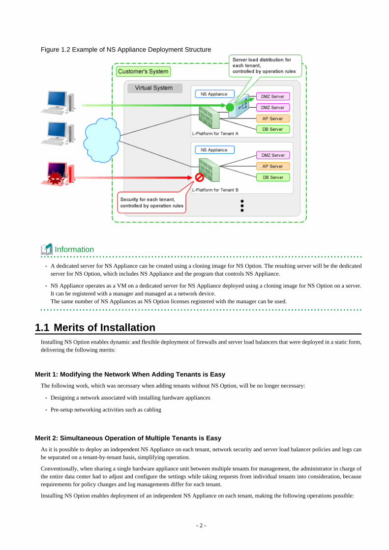
Figure 1.2 Example of NS Appliance Deployment Structure
Information
- A dedicated server for NS Appliance can be created using a cloning image for NS Option. The resulting server will be the dedicatedserver for NS Option, which includes NS Appliance and the program that controls NS Appliance.
- NS Appliance operates as a VM on a dedicated server for NS Appliance deployed using a cloning image for NS Option on a server.It can be registered with a manager and managed as a network device.The same number of NS Appliances as NS Option licenses registered with the manager can be used.
1.1 Merits of InstallationInstalling NS Option enables dynamic and flexible deployment of firewalls and server load balancers that were deployed in a static form,delivering the following merits:
Merit 1: Modifying the Network When Adding Tenants is Easy
The following work, which was necessary when adding tenants without NS Option, will be no longer necessary:
- Designing a network associated with installing hardware appliances
- Pre-setup networking activities such as cabling
Merit 2: Simultaneous Operation of Multiple Tenants is Easy
As it is possible to deploy an independent NS Appliance on each tenant, network security and server load balancer policies and logs canbe separated on a tenant-by-tenant basis, simplifying operation.
Conventionally, when sharing a single hardware appliance unit between multiple tenants for management, the administrator in charge ofthe entire data center had to adjust and configure the settings while taking requests from individual tenants into consideration, becauserequirements for policy changes and log managements differ for each tenant.
Installing NS Option enables deployment of an independent NS Appliance on each tenant, making the following operations possible:
- 2 -
- Each tenant administrator can change the policy without affecting other tenants.
- As the log can be separated on a tenant-by-tenant basis, management is simplified.
1.2 Function OverviewThis section explains the security functions provided by NS Appliance.
NS Appliance provides the following security functions:
- Access Control Function
- Network Address Translation Function
- Anomaly-based IPS Function
- Routing Function
- Server Load Balancer Function
- High-availability Function
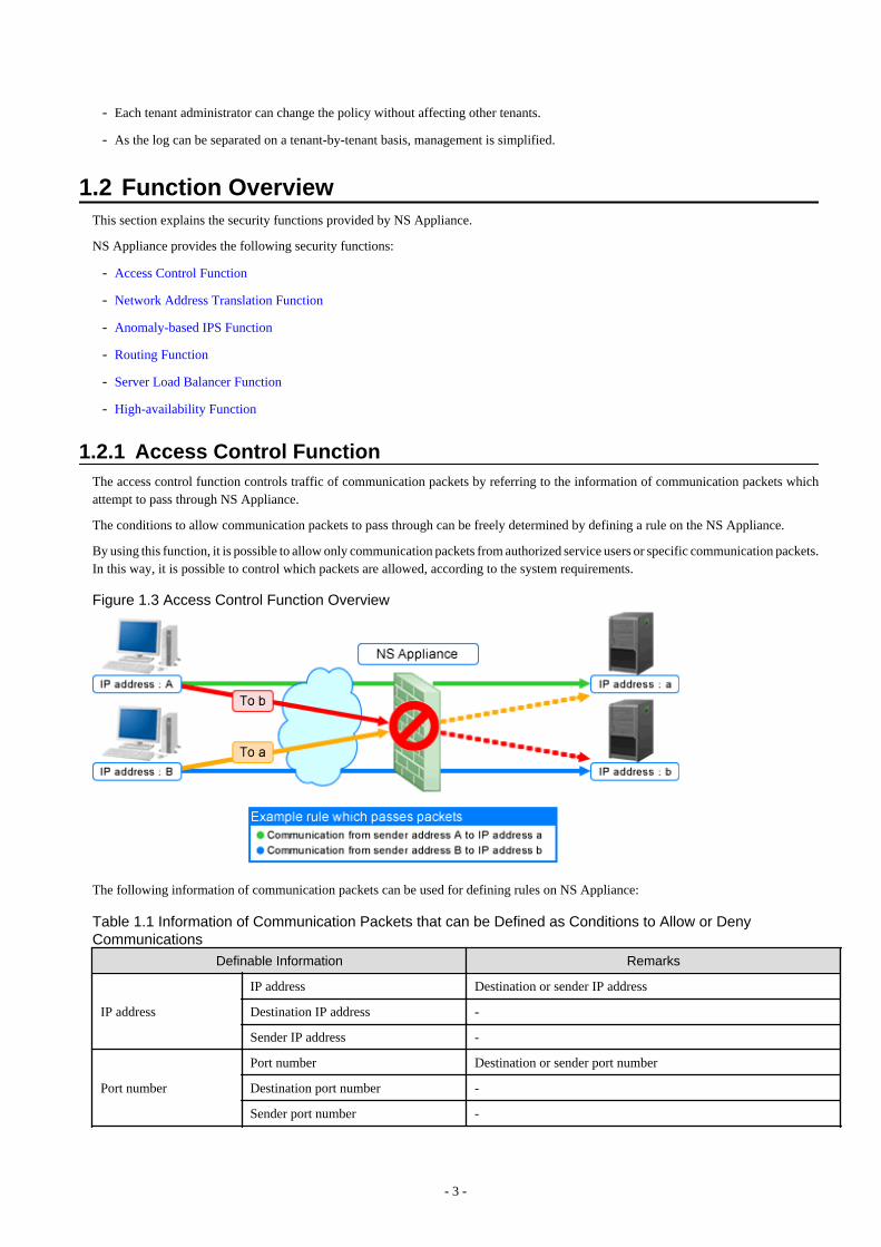
1.2.1 Access Control FunctionThe access control function controls traffic of communication packets by referring to the information of communication packets whichattempt to pass through NS Appliance.
The conditions to allow communication packets to pass through can be freely determined by defining a rule on the NS Appliance.
By using this function, it is possible to allow only communication packets from authorized service users or specific communication packets.In this way, it is possible to control which packets are allowed, according to the system requirements.
Figure 1.3 Access Control Function Overview
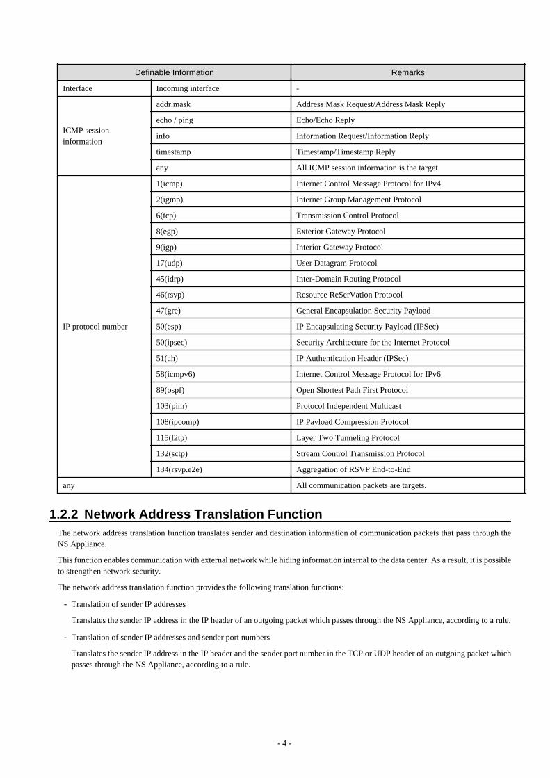
The following information of communication packets can be used for defining rules on NS Appliance:
Table 1.1 Information of Communication Packets that can be Defined as Conditions to Allow or DenyCommunications
Definable Information Remarks
IP address
IP address Destination or sender IP address
Destination IP address -
Sender IP address -
Port number
Port number Destination or sender port number
Destination port number -
Sender port number -
- 3 -
Definable Information Remarks
Interface Incoming interface -
ICMP sessioninformation
addr.mask Address Mask Request/Address Mask Reply
echo / ping Echo/Echo Reply
info Information Request/Information Reply
timestamp Timestamp/Timestamp Reply
any All ICMP session information is the target.
IP protocol number
1(icmp) Internet Control Message Protocol for IPv4
2(igmp) Internet Group Management Protocol
6(tcp) Transmission Control Protocol
8(egp) Exterior Gateway Protocol
9(igp) Interior Gateway Protocol
17(udp) User Datagram Protocol
45(idrp) Inter-Domain Routing Protocol
46(rsvp) Resource ReSerVation Protocol
47(gre) General Encapsulation Security Payload
50(esp) IP Encapsulating Security Payload (IPSec)
50(ipsec) Security Architecture for the Internet Protocol
51(ah) IP Authentication Header (IPSec)
58(icmpv6) Internet Control Message Protocol for IPv6
89(ospf) Open Shortest Path First Protocol
103(pim) Protocol Independent Multicast
108(ipcomp) IP Payload Compression Protocol
115(l2tp) Layer Two Tunneling Protocol
132(sctp) Stream Control Transmission Protocol
134(rsvp.e2e) Aggregation of RSVP End-to-End
any All communication packets are targets.
1.2.2 Network Address Translation FunctionThe network address translation function translates sender and destination information of communication packets that pass through theNS Appliance.
This function enables communication with external network while hiding information internal to the data center. As a result, it is possibleto strengthen network security.
The network address translation function provides the following translation functions:
- Translation of sender IP addresses
Translates the sender IP address in the IP header of an outgoing packet which passes through the NS Appliance, according to a rule.
- Translation of sender IP addresses and sender port numbers
Translates the sender IP address in the IP header and the sender port number in the TCP or UDP header of an outgoing packet whichpasses through the NS Appliance, according to a rule.
- 4 -
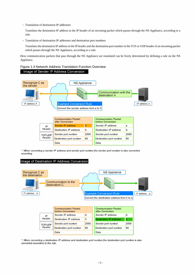
- Translation of destination IP addresses
Translates the destination IP address in the IP header of an incoming packet which passes through the NS Appliance, according to arule.
- Translation of destination IP addresses and destination port numbers
Translates the destination IP address in the IP header and the destination port number in the TCP or UDP header of an incoming packetwhich passes through the NS Appliance, according to a rule.
How communication packets that pass through the NS Appliance are translated can be freely determined by defining a rule on the NSAppliance.
Figure 1.4 Network Address Translation Function Overview
- 5 -
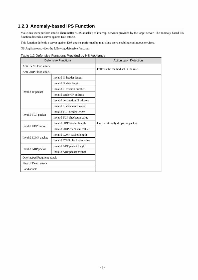
1.2.3 Anomaly-based IPS FunctionMalicious users perform attacks (hereinafter "DoS attacks") to interrupt services provided by the target server. The anomaly-based IPSfunction defends a server against DoS attacks.
This function defends a server against DoS attacks performed by malicious users, enabling continuous services.
NS Appliance provides the following defensive functions:
Table 1.2 Defensive Functions Provided by NS Appliance
Defensive Functions Action upon Detection
Anti SYN Flood attackFollows the method set in the rule.
Anti UDP Flood attack
Invalid IP packet
Invalid IP header length
Unconditionally drops the packet.
Invalid IP data length
Invalid IP version number
Invalid sender IP address
Invalid destination IP address
Invalid IP checksum value
Invalid TCP packetInvalid TCP header length
Invalid TCP checksum value
Invalid UDP packetInvalid UDP header length
Invalid UDP checksum value
Invalid ICMP packetInvalid ICMP packet length
Invalid ICMP checksum value
Invalid ARP packetInvalid ARP packet length
Invalid ARP packet format
Overlapped Fragment attack
Ping of Death attack
Land attack
- 6 -

Figure 1.5 Anti SYN Flood Attack Function Overview
1.2.4 Routing FunctionRouting information is the function to control the destination to send the communication packets based on the route information. Thereare two types of functions. One of which is statistic routing for configuring the route information in advance, and the other is dynamicrouting for dynamically updating the route information.
NS appliances provide the following routing functions:
Table 1.3 Routing Functions Provided by NS Appliance
Functions Remarks
Static routing
Dynamic routing RIPv1 The version of RIP to use can be specified.
Triggered update or split horizon are always valid.
- Differences between RIPv1 and RIPv2
RIPv1 is a prerequisite for using the same subnet mask in the same networkaddress.
Sends RIP messages using IP broadcast addresses.
More than two types of subnet masks can be used for RIPv2.
Use the IP multicast address (224.0.0.9) in order to send RIP messages.
Variable Length Subnet Mask (VLSM) and Classless Inter-DomainRouting (CIDR) are supported.
When using NS appliances, the following functions are not supported.
RIPv2
- 7 -
Functions Remarks
- Unicast RIP (limited to adjacent routers)
- Silent RIP (RIP, not published)
- Metric value manipulation
- RIPv2 authentication
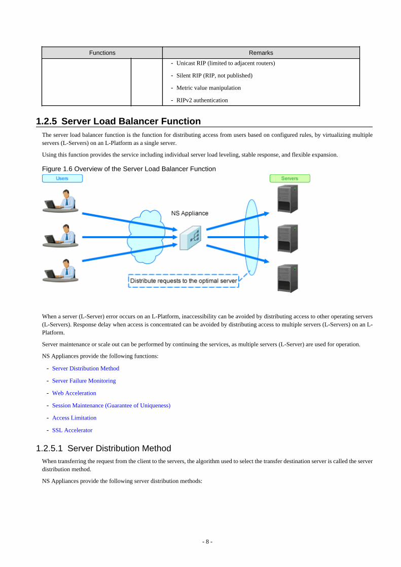
1.2.5 Server Load Balancer FunctionThe server load balancer function is the function for distributing access from users based on configured rules, by virtualizing multipleservers (L-Servers) on an L-Platform as a single server.
Using this function provides the service including individual server load leveling, stable response, and flexible expansion.
Figure 1.6 Overview of the Server Load Balancer Function
When a server (L-Server) error occurs on an L-Platform, inaccessibility can be avoided by distributing access to other operating servers(L-Servers). Response delay when access is concentrated can be avoided by distributing access to multiple servers (L-Servers) on an L-Platform.
Server maintenance or scale out can be performed by continuing the services, as multiple servers (L-Server) are used for operation.
NS Appliances provide the following functions:
- Server Distribution Method
- Server Failure Monitoring
- Web Acceleration
- Session Maintenance (Guarantee of Uniqueness)
- Access Limitation
- SSL Accelerator
1.2.5.1 Server Distribution MethodWhen transferring the request from the client to the servers, the algorithm used to select the transfer destination server is called the serverdistribution method.
NS Appliances provide the following server distribution methods:
- 8 -

Table 1.4 List of Server Distribution Methods Provided by NS AppliancesServer Distribution Method Description
Round robin Transfers requests from the client to the server in order, regardless of the load of eachdistribution target server.
Simple number of minimum connections Transfers the access from the client to the server with the minimum number of connections,based on the number of connections being processed by each distribution target server.
1.2.5.2 Server Failure MonitoringMonitors the operating statuses of servers, and when a failure is detected the failed server or application is excluded from the targets oftransfer of requests from clients.
Figure 1.7 Overview of the Server Failure Monitoring
NS appliances provide the following server failure monitoring:
Table 1.5 List of Server Failure Monitoring Provided by NS Appliances
Server Failure Monitoring Description
Device monitoring(Layer 3 level health check)
Monitors server failure depending on whether a response is received, by sending PINGs(ICMP Echo requests) at specified intervals
Service monitoring(Layer 4 level health check)
Monitors the operating status of applications based on the response for the TCP port andthe UDP port of the applications operating on each server.
Checks if a TCP connection is established for the TCP port.
When a UDP probe packet is sent to the UDP port, if there is no response, it is regardedas normal. When ICMP unreachable packets are received, it is regarded as an error.
Application monitoring(Layer 7 level health check)
Supports the operation status of applications by monitoring their responses to requestssent to the application layers.
Supports monitoring of the following application:
- HTTP
Issues the HEAD or GET requests using the specified URL path names, and monitorsthe response codes.
The following functions are provided as the option functions of server failure monitoring.
- 9 -
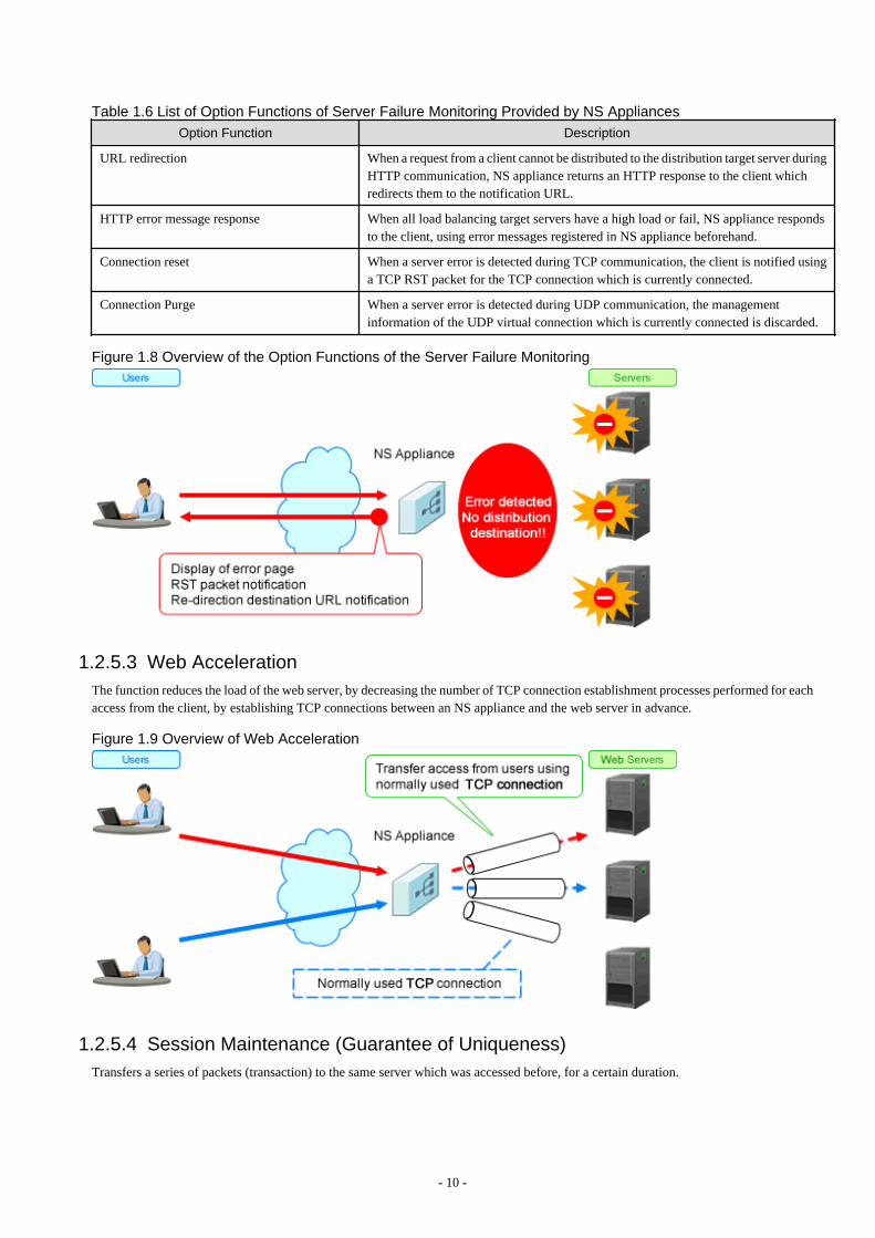
Table 1.6 List of Option Functions of Server Failure Monitoring Provided by NS AppliancesOption Function Description
URL redirection When a request from a client cannot be distributed to the distribution target server duringHTTP communication, NS appliance returns an HTTP response to the client whichredirects them to the notification URL.
HTTP error message response When all load balancing target servers have a high load or fail, NS appliance respondsto the client, using error messages registered in NS appliance beforehand.
Connection reset When a server error is detected during TCP communication, the client is notified usinga TCP RST packet for the TCP connection which is currently connected.
Connection Purge When a server error is detected during UDP communication, the managementinformation of the UDP virtual connection which is currently connected is discarded.
Figure 1.8 Overview of the Option Functions of the Server Failure Monitoring
1.2.5.3 Web AccelerationThe function reduces the load of the web server, by decreasing the number of TCP connection establishment processes performed for eachaccess from the client, by establishing TCP connections between an NS appliance and the web server in advance.
Figure 1.9 Overview of Web Acceleration
1.2.5.4 Session Maintenance (Guarantee of Uniqueness)Transfers a series of packets (transaction) to the same server which was accessed before, for a certain duration.
- 10 -
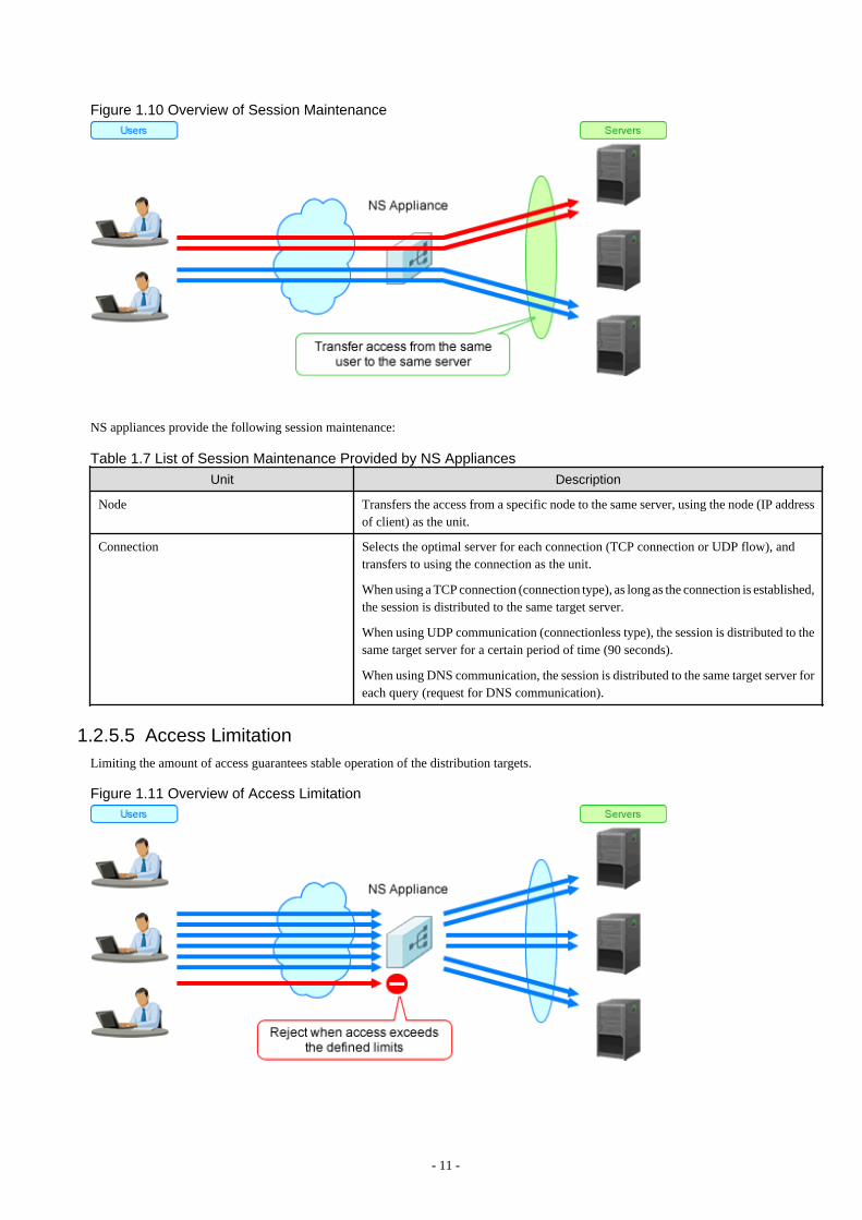
Figure 1.10 Overview of Session Maintenance
NS appliances provide the following session maintenance:
Table 1.7 List of Session Maintenance Provided by NS Appliances
Unit Description
Node Transfers the access from a specific node to the same server, using the node (IP addressof client) as the unit.
Connection Selects the optimal server for each connection (TCP connection or UDP flow), andtransfers to using the connection as the unit.
When using a TCP connection (connection type), as long as the connection is established,the session is distributed to the same target server.
When using UDP communication (connectionless type), the session is distributed to thesame target server for a certain period of time (90 seconds).
When using DNS communication, the session is distributed to the same target server foreach query (request for DNS communication).
1.2.5.5 Access LimitationLimiting the amount of access guarantees stable operation of the distribution targets.
Figure 1.11 Overview of Access Limitation
- 11 -

NS Appliance provides the following access limitation:
Table 1.8 List of Access Limitation Provided by NS Appliances
Limitation Target Description
Number of nodes Limits clustered servers based on the number of the nodes.
When the access limit is exceeded, packets received from the client are discarded.
Number of connections Limits clustered servers based on the number of connections.
When the access limit is exceeded, packets received from the client are discarded.
1.2.5.6 SSL AcceleratorThis function enables load distribution by converting HTTPS to HTTP communication, and improves the high availability of web servers(L-Servers).
Figure 1.12 Overview of SSL Accelerator
SSL encryption and decryption during HTTP communication by NS appliance makes it possible to show the communication as the HTTPcommunication of a web server (L-Server). It is not necessary to prepare the encryption function for each web server (L-Server).
NS Appliance supports the following protocols and allows for their customization:
- SSLv3.0
- TLSv1.0
NS Appliance supports the following cipher suites and allows for their customization:
For a CA certificate, the key length can be up to 4,096 bits, and for a server certificate, the key length can be up to 2,048 bits.
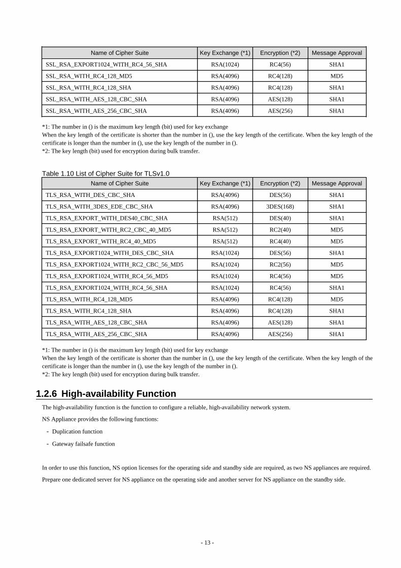
Table 1.9 List of Cipher Suite for SSLv3.0
Name of Cipher Suite Key Exchange (*1) Encryption (*2) Message Approval
SSL_RSA_WITH_DES_CBC_SHA RSA(4096) DES(56) SHA1
SSL_RSA_WITH_3DES_EDE_CBC_SHA RSA(4096) 3DES(168) SHA1
SSL_RSA_EXPORT_WITH_DES40_CBC_SHA RSA(512) DES(40) SHA1
SSL_RSA_EXPORT_WITH_RC2_CBC_40_MD5 RSA(512) RC2(40) MD5
SSL_RSA_EXPORT_WITH_RC4_40_MD5 RSA(512) RC4(40) MD5
SSL_RSA_EXPORT1024_WITH_DES_CBC_SHA RSA(1024) DES(56) SHA1
SSL_RSA_EXPORT1024_WITH_RC2_CBC_56_MD5 RSA(1024) RC2(56) MD5
SSL_RSA_EXPORT1024_WITH_RC4_56_MD5 RSA(1024) RC4(56) MD5
- 12 -
Name of Cipher Suite Key Exchange (*1) Encryption (*2) Message Approval
SSL_RSA_EXPORT1024_WITH_RC4_56_SHA RSA(1024) RC4(56) SHA1
SSL_RSA_WITH_RC4_128_MD5 RSA(4096) RC4(128) MD5
SSL_RSA_WITH_RC4_128_SHA RSA(4096) RC4(128) SHA1
SSL_RSA_WITH_AES_128_CBC_SHA RSA(4096) AES(128) SHA1
SSL_RSA_WITH_AES_256_CBC_SHA RSA(4096) AES(256) SHA1
*1: The number in () is the maximum key length (bit) used for key exchangeWhen the key length of the certificate is shorter than the number in (), use the key length of the certificate. When the key length of thecertificate is longer than the number in (), use the key length of the number in ().*2: The key length (bit) used for encryption during bulk transfer.
Table 1.10 List of Cipher Suite for TLSv1.0
Name of Cipher Suite Key Exchange (*1) Encryption (*2) Message Approval
TLS_RSA_WITH_DES_CBC_SHA RSA(4096) DES(56) SHA1
TLS_RSA_WITH_3DES_EDE_CBC_SHA RSA(4096) 3DES(168) SHA1
TLS_RSA_EXPORT_WITH_DES40_CBC_SHA RSA(512) DES(40) SHA1
TLS_RSA_EXPORT_WITH_RC2_CBC_40_MD5 RSA(512) RC2(40) MD5
TLS_RSA_EXPORT_WITH_RC4_40_MD5 RSA(512) RC4(40) MD5
TLS_RSA_EXPORT1024_WITH_DES_CBC_SHA RSA(1024) DES(56) SHA1
TLS_RSA_EXPORT1024_WITH_RC2_CBC_56_MD5 RSA(1024) RC2(56) MD5
TLS_RSA_EXPORT1024_WITH_RC4_56_MD5 RSA(1024) RC4(56) MD5
TLS_RSA_EXPORT1024_WITH_RC4_56_SHA RSA(1024) RC4(56) SHA1
TLS_RSA_WITH_RC4_128_MD5 RSA(4096) RC4(128) MD5
TLS_RSA_WITH_RC4_128_SHA RSA(4096) RC4(128) SHA1
TLS_RSA_WITH_AES_128_CBC_SHA RSA(4096) AES(128) SHA1
TLS_RSA_WITH_AES_256_CBC_SHA RSA(4096) AES(256) SHA1
*1: The number in () is the maximum key length (bit) used for key exchangeWhen the key length of the certificate is shorter than the number in (), use the key length of the certificate. When the key length of thecertificate is longer than the number in (), use the key length of the number in ().*2: The key length (bit) used for encryption during bulk transfer.
1.2.6 High-availability FunctionThe high-availability function is the function to configure a reliable, high-availability network system.
NS Appliance provides the following functions:
- Duplication function
- Gateway failsafe function
In order to use this function, NS option licenses for the operating side and standby side are required, as two NS appliances are required.
Prepare one dedicated server for NS appliance on the operating side and another server for NS appliance on the standby side.
- 13 -
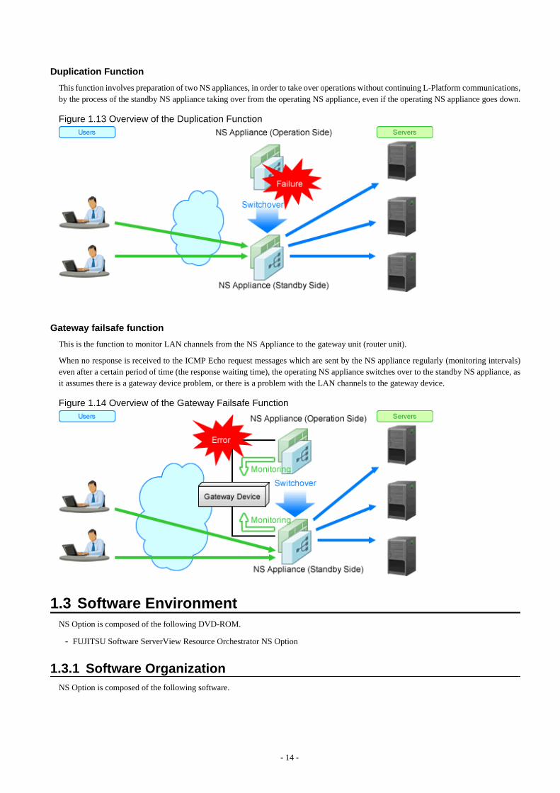
Duplication Function
This function involves preparation of two NS appliances, in order to take over operations without continuing L-Platform communications,by the process of the standby NS appliance taking over from the operating NS appliance, even if the operating NS appliance goes down.
Figure 1.13 Overview of the Duplication Function
Gateway failsafe function
This is the function to monitor LAN channels from the NS Appliance to the gateway unit (router unit).
When no response is received to the ICMP Echo request messages which are sent by the NS appliance regularly (monitoring intervals)even after a certain period of time (the response waiting time), the operating NS appliance switches over to the standby NS appliance, asit assumes there is a gateway device problem, or there is a problem with the LAN channels to the gateway device.
Figure 1.14 Overview of the Gateway Failsafe Function
1.3 Software EnvironmentNS Option is composed of the following DVD-ROM.
- FUJITSU Software ServerView Resource Orchestrator NS Option
1.3.1 Software OrganizationNS Option is composed of the following software.
- 14 -
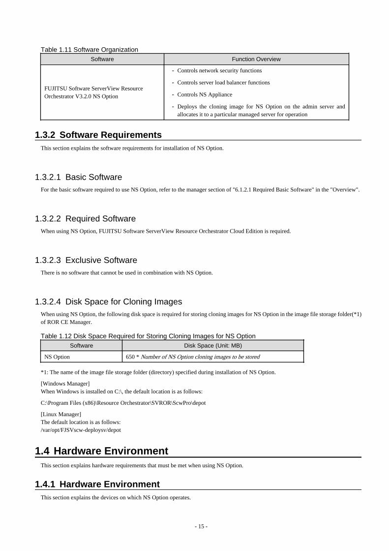
Table 1.11 Software OrganizationSoftware Function Overview
FUJITSU Software ServerView ResourceOrchestrator V3.2.0 NS Option
- Controls network security functions
- Controls server load balancer functions
- Controls NS Appliance
- Deploys the cloning image for NS Option on the admin server andallocates it to a particular managed server for operation
1.3.2 Software RequirementsThis section explains the software requirements for installation of NS Option.
1.3.2.1 Basic SoftwareFor the basic software required to use NS Option, refer to the manager section of "6.1.2.1 Required Basic Software" in the "Overview".
1.3.2.2 Required SoftwareWhen using NS Option, FUJITSU Software ServerView Resource Orchestrator Cloud Edition is required.
1.3.2.3 Exclusive SoftwareThere is no software that cannot be used in combination with NS Option.
1.3.2.4 Disk Space for Cloning ImagesWhen using NS Option, the following disk space is required for storing cloning images for NS Option in the image file storage folder(*1)of ROR CE Manager.
Table 1.12 Disk Space Required for Storing Cloning Images for NS Option
Software Disk Space (Unit: MB)
NS Option 650 * Number of NS Option cloning images to be stored
*1: The name of the image file storage folder (directory) specified during installation of NS Option.
[Windows Manager]When Windows is installed on C:\, the default location is as follows:
C:\Program Files (x86)\Resource Orchestrator\SVROR\ScwPro\depot
[Linux Manager]The default location is as follows:/var/opt/FJSVscw-deploysv/depot
1.4 Hardware EnvironmentThis section explains hardware requirements that must be met when using NS Option.
1.4.1 Hardware EnvironmentThis section explains the devices on which NS Option operates.
- 15 -

Table 1.13 Required Hardware Conditions
Hardware Remarks
Blade servers
Chassis PRIMERGY BX900 chassis -
Server bladesPRIMERGY BX924 S2PRIMERGY BX924 S3PRIMERGY BX924 S4
- Only on-board NICs can be used.(Do not mount a LAN expansion card.)
- Disable the UMC(Universal Multi-Channel) function of on-board NICs.
- NIC1 and NIC2 are used as the NICs of theadmin LAN and public LAN by performingredundancy.
- When using SAN storage, VIOM isnecessary.
- When using SAN storage, use an EmulexFibre Channel card.
LAN switch blades
PY-SWB104(PG-SW109) Mount this on CB1 and CB2.
Fujitsu PRIMERGY ConvergedFabric Switch Blade (10Gbps18/8+2)
- Mount this on CB1 and CB2.
- Only the default VFAB or a single virtualfabric configuration can be used.
Rack mount serversPRIMERGY RX300 S7PRIMERGY RX300 S8
- An on-board or LAN expansion card can beused.
- NIC1 and NIC2 of the on-board NICs areused as the NICs of the admin LAN andpublic LAN by performing redundancy.Also, NIC3 and NIC4 of a LAN expansioncard NIC are used by performingredundancy.
- Only one Dual port LAN card can be usedas a LAN expansion card. Do not mount twoor more Dual port LAN cards, or other LANexpansion cards.
- When using SAN storage, VIOM isnecessary.
- When using SAN storage, use an EmulexFibre Channel card.
Storage SAN StorageStorage device that can beconnected with Physical L-Server.
Necessary when deploying the physical L-Server of an NS appliance on SAN storage.Do not mount an internal disk on a server.
- When Using FC Multi-path Configuration
Use the following storage units:
- ETERNUS DX8000 Series
- ETERNUS DX8000 S2 Series
- ETERNUS DX600 S3
- ETERNUS DX500 S3
- ETERNUS DX400 Series
- ETERNUS DX400 S2 Series
- 16 -

Hardware Remarks
- ETERNUS DX200 S3
- ETERNUS DX200F
- ETERNUS DX100 S3
- ETERNUS DX90 S2
- ETERNUS DX90
- ETERNUS DX80 S2
- ETERNUS DX80
- ETERNUS DX60 S2
- ETERNUS DX60
The following multi-path configurations aresupported:
- Dual Path Configuration
- Failover Configuration
- When Using FC Single-path Configuration
Use the storage units that can be connectedwith physical L-Servers.
For the storage that can be connected tophysical L-Servers, refer to "6.2.3 CloudEdition" in the "Overview".
Internal Disk of aServer
SAS SSDSAS HDD
An internal disk with an SAS connection can beused.Necessary when deploying the physical serverof an NS appliance on the internal disk of aserver.Do not connect with SAN storage.
For the L2 switches that can be used with this product, refer to "6.2.3 Cloud Edition" in the "Overview".
1.4.2 Specifications Required for Servers Dedicated to NS ApplianceSpecifications required for dedicated servers for NS Appliance are as follow:
CPU
A dual core CPU or higher is required.
Memory Size
The required memory size is as follows:
Table 1.14 Required Memory Size
Item Memory Size (Unit: MB)
Server 6,144 or larger
Estimate the memory size required for the server, using the following formula:
- 17 -

Memory size necessary for a server = 4096 + 2048 * Number of NS appliances created asfirewalls(*1) + 4096 * Number of NS appliances created as integrated network devices (*1)
*1: A total of 10 instances of NS Appliance can be created on each dedicated server for NS Appliance.
Disk Space
The disk space required for deploying a dedicated server for NS Appliance is shown below:
Table 1.15 Disk Space Required for Deploying a Dedicated Server for NS Appliance
Item Disk Space (Unit: GB) (*1) Remarks
A dedicated server for NS Appliance
100When operating up to 10 instances of NS Applianceon each dedicated server for NS Appliances
175When operating up to 20 instances of NS Applianceon each dedicated server for NS Appliances
*1: The static disk space required regardless of the number of NS Appliances created on a dedicated server.
Information
When using rack mount servers, and also when using the internal disk in the storage, other devices (example: DVDs) connected using"SATA" cannot be used.
1.4.3 Admin LAN NIC ConfigurationThis section explains the admin LAN NIC configuration of physical L-Servers for NS Appliance.
It is necessary to configure the NICs which are used for the admin LAN of the physical L-Server for NS Appliance in a redundantconfiguration.
If NICs are not in a redundant configuration, NS Appliance creation will fail.
The combinations of NICs that can be configured in redundant configurations are as follows:
Table 1.16 When Using PRIMERGY BX900 Chassis
Blade Server NIC in Redundant Configuration(Physical Network Adapter Number)
Remarks
PRIMERGY BX924 S2PRIMERGY BX924 S3PRIMERGY BX924 S4
1, 2 NIC1 and NIC2 of the on-board NICs areused as the NICs of the admin LAN andpublic LAN by performing redundancy.
Table 1.17 When Using Rack Mount Servers
Rack Mount Server NIC in Redundant Configuration(Physical Network Adapter Number)
Remarks
PRIMERGY RX300 S7PRIMERGY RX300 S8
2 arbitrary NICs NIC1 and NIC2 of the on-board NICs areused as the NICs of the admin LAN andpublic LAN by performing redundancy.Also, NIC3 and NIC4 of a LAN expansioncard NIC are used by performingredundancy.
1.5 High AvailabilityThis section explains high availability of NS Appliance.
- 18 -

1.5.1 When Using SAN StorageThis section explains high availability when using the storage used in the environment on which the NS appliance is deployed.
- High Availability as a Resource
- Physical L-Server redundancy
When server recovery is specified during creation of a physical L-Server for NS Appliance, if an error is detected on the serverwhere the physical L-Server is deployed, it is possible to switch to its spare server for automatic switchover.
- Server switchover when a chassis fails
If a chassis in a configuration where ROR CE manages multiple chassis fails, operations can be re-started by starting the physicalL-Server on a chassis that operational.
- Switchover of operating or standby status of storage
Realizes the switchover between operating and standby disks in configurations in which replication of the operating storage volumeused by a physical L-Server to a standby storage volume is configured.
- Redundant Storage and FC Path Configuration
After creation of a physical L-Server for NS Appliance, making the FC path configuration redundant enables multi-pathconfiguration between the physical L-Server and storage. By enabling the multi-path configuration, it is possible to prevent anoperation from stopping due to a path error during operation.
- Redundancy Function of NS Appliance
This function is to take over operations without continuing L-Platform communications, by the process of a standby NS Appliancetaking over from the operating NS Appliance, even if the operating NS Appliance goes down.For details on the redundancy function of NS Appliance, refer to "1.2.6 High-availability Function".
See
For details on high availability of managed resources, refer to "Chapter 18 High Availability of Managed Resources" in the "OperationGuide CE".
- Disaster Recovery
Physical L-Servers for NS Appliances are targets of Disaster Recovery.
For details, refer to "4.3 Disaster Recovery Operations".
1.5.2 When Using Internal Disks of a ServerThis section explains high availability when using the internal disk of the server used in the environment on which the NS appliance isdeployed.
- High Availability as a Resource
- Redundancy Function of NS Appliance
This function is to take over operations without continuing L-Platform communications, by the process of a standby NS Appliancetaking over from the operating NS Appliance, even if the operating NS Appliance goes down.For details on the redundancy function of NS Appliance, refer to "1.2.6 High-availability Function".
- Disaster Recovery
Physical servers for NS Appliances are not the targets of Disaster Recovery.When taking over the settings of an NS Appliance being used by a primary site to the backup site, perform the following procedure:
1. Regularly back up the definition of the NS Appliance of the primary site.For details, refer to "10.2.2 Backup of Network Devices" in the "Operation Guide CE".
2. Restore the definition backed up in step 1 to an NS Appliance when migrating to the backup site.For details, refer to "10.2.3 Restoration of Network Devices" in the "Operation Guide CE".
- 19 -
Chapter 2 Design and PreparationsThis chapter explains the design and preparations necessary for using NS Option.
2.1 DesignWhen using an NS Appliance, decide the following information from within the system to be created using ROR CE.For the configuration of an entire ROR CE system, refer to "2.6 System Configuration" in the "Design Guide CE".
- Designing the Server and Storage Environment
Decide the number of servers and storage required to use the NS Appliance.
- Designing the Network Environment
Design the network configuration for the environment using NS Appliance.
- Designing the L-Platform Network Environment
Decide the information necessary to design the network environment of the L-Platform where the NS Appliance will be used.
- Resource Pools
Define the usage method of resource pools associated with NS Appliance.
2.1.1 Designing the Server and Storage EnvironmentDefine the servers and storage required to use an NS Appliance.
How to Define Servers
Define the servers to be used for NS Appliances.
1. Determine how many NS Appliances are necessary.
When using the redundancy function of NS Appliances, design the environment with two NS Appliances (one for active and anotherfor stand-by).
2. Determine how many servers are necessary.
Based on the specifications (CPU and memory size) of the dedicated servers for NS Appliances, determine how many NS Applianceswill operate on each server, and then determine how many servers are required to operate the same number of NS Appliancecalculated in step 1.Note the following points:
- For details on required specifications for servers that can be used for NS Option, refer to "1.4.2 Specifications Required forServers Dedicated to NS Appliance".
- When using the redundancy function of NS Appliances, it is necessary to configure active NS Appliances and stand-by NSAppliances on separate dedicated servers.
- A total of 20 instances of NS Appliance can operate on each dedicated server for NS Appliances.The required memory size and disk space differ depending on the maximum number of NS Appliances that will be operated.For details, refer to "1.4.2 Specifications Required for Servers Dedicated to NS Appliance".
3. Determine the servers to use.
Determine as many servers as the number of the servers for NS Appliances estimated in step 2.
- When installing NS Option at the same time as ROR CE
Define the servers and specification of the system to be created using ROR CE, including the servers to be used for NS Option.
- When installing NS Option on a system with ROR CE installed
Define the servers to be used for NS Option from among the servers in the system.If no servers satisfy the requirements, add servers that satisfy the requirements.
- 20 -

How to Define Storage
Define the storage to be used for NS Appliances.
1. Define the required disk space based on the number of servers estimated in "How to Define Servers".
2. Define the storage to use.
- When installing NS Option at the same time as ROR CE
Define the storage and specifications (FC path connection configuration, etc.) of the system to be created using ROR CE,including the storage to be used for NS Option.For details on the storage that can be used for NS Option, refer to "1.4 Hardware Environment".
- When installing NS Option on a system with ROR CE installed
Define the storage and its connection configuration to be used for NS Option from among the storage in the system that meetsthe requirements described in "1.4 Hardware Environment".If no storage satisfies the requirements, add storage that satisfies the requirements.
An example of estimating the number of servers and disk space of the storage is given below:
Example
In this example, two servers are required because the CPU and disk size meet the requirements for servers dedicated to NS Appliancesbut the memory size is insufficient.
For details on specifications required for servers, refer to "1.4.2 Specifications Required for Servers Dedicated to NS Appliance".
- Number of NS Appliances: 6
- For use as firewalls: 4 (Required memory size: 8 GB)
- For use as integrated network devices: 2 (Required memory size: 8 GB)
- Server specifications (Common to all servers)
- CPU: Intel(R) Xeon(R) Processor L5609
- Memory size: 12 GB
- Disk space: 300 GB
Figure 2.1 Example Estimate of Required Number of Servers
- 21 -

2.1.1.1 Blade serversThis section explains system configuration using NS Appliance with blade servers. "Figure 2.2 Example of Blade Server SystemConfiguration" is an example of a system configuration using SAN storage. For details on the hardware that can be used, refer to "1.4Hardware Environment".
Figure 2.2 Example of Blade Server System Configuration
ROR Manager
Software required for the use of NS Option operating on the admin server. A CE license is required.
ServerView Operations Manager
Software that monitors the hardware status of servers (PRIMERGY) and sends notification of any errors detected via the network.
ServerView Virtual-IO Manager
Software that provides I/O virtualization technology which changes WWNs retained by server HBAs and MAC addresses retained byNICs.This software is necessary when using SAN storage.
ETERNUS SF Storage Cruiser
Software used for management of configurations, relationships, troubles, and performance of storage related resources such asETERNUS.This software is necessary when using SAN storage.
Blade Server (for L-Servers)
The blade server for deploying L-Servers during L-Platform creation.
ROR Agent
An ROR CE program that operates on a managed server.
Blade Server (Dedicated to NS Option)
A dedicated server for NS Option, on which a physical L-Server is deployed using a cloning image for NS Option to operate NSAppliance.
- 22 -
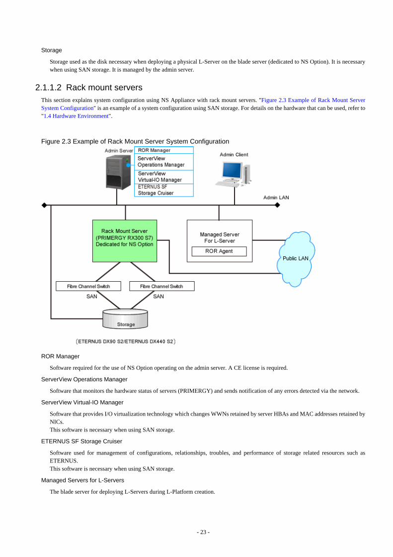
Storage
Storage used as the disk necessary when deploying a physical L-Server on the blade server (dedicated to NS Option). It is necessarywhen using SAN storage. It is managed by the admin server.
2.1.1.2 Rack mount serversThis section explains system configuration using NS Appliance with rack mount servers. "Figure 2.3 Example of Rack Mount ServerSystem Configuration" is an example of a system configuration using SAN storage. For details on the hardware that can be used, refer to"1.4 Hardware Environment".
Figure 2.3 Example of Rack Mount Server System Configuration
ROR Manager
Software required for the use of NS Option operating on the admin server. A CE license is required.
ServerView Operations Manager
Software that monitors the hardware status of servers (PRIMERGY) and sends notification of any errors detected via the network.
ServerView Virtual-IO Manager
Software that provides I/O virtualization technology which changes WWNs retained by server HBAs and MAC addresses retained byNICs.This software is necessary when using SAN storage.
ETERNUS SF Storage Cruiser
Software used for management of configurations, relationships, troubles, and performance of storage related resources such asETERNUS.This software is necessary when using SAN storage.
Managed Servers for L-Servers
The blade server for deploying L-Servers during L-Platform creation.
- 23 -
ROR Agent
An ROR CE program that operates on a managed server.
Rack Mount Server (Dedicated to NS Option)
A dedicated server for NS Option, on which a physical L-Server is deployed using a cloning image for NS Option to operate NSAppliance.
Storage
Storage used as the disk necessary when deploying a physical L-Server on the rack mount server (dedicated to NS Option). It isnecessary when using SAN storage. It is managed by the admin server.
2.1.2 Designing the Network EnvironmentIn order to design the network configuration for using NS Appliance, define the following information:
The information defined here will be used when configuring the environment of NS Appliance and when registering network devices.
- Host name (equivalent to the device name for a network device)
- SNMP community
- Administrator information (user name, password, and privileged administrator password)
- Management method (PING, SNMP)
- Admin IP address, VLAN ID
- Define the IP address and VLAN ID of the network used by dedicated servers for NS Appliances and individual NS Appliances.In the following cases, use different VLANs for the dedicated servers for NS Appliances and individual NS Appliances.
- When ensuring the security of the admin LAN of each tenant individually
- When there are not enough IP addresses on the admin LAN
In the example network configuration shown below, "100" is used for the VLAN ID and the same VLAN is used for the dedicatedservers for NS Appliances and individual NS Appliances.
- Admin LAN settings
- When using the same VLAN for the dedicated servers for NS Appliances and individual NS Appliances
For the admin LAN for the NS Appliances, configure a VLAN (untagged).
- When using different VLANs for the dedicated servers for NS Appliances and individual NS Appliances
For the admin LAN for the NS Appliances, configure a VLAN (tagged).
- Communication Route (NIC)
- For the NICs to be used, refer to "1.4.3 Admin LAN NIC Configuration".
- NICs are shared between the public LAN and the admin LAN.
- Admin LAN routing information (routing information)
Define the following items during "2.1.3 Designing the L-Platform Network Environment".
- NS Appliance type (firewall or integrated network device) and automatic configuration modes
- Public LAN IP address, VLAN ID
- Public LAN routing information (routing information)
- Number of L-Platforms which can be deployed on an NS appliance
For the same content as the one applied for ROR CE, refer to "Chapter 9 Defining and Configuring the Network Environment" in the"Design Guide CE", as that content is omitted from this manual.
- 24 -
2.1.3 Designing the L-Platform Network EnvironmentDecide the following information to design the network environment of the L-Platform where NS Appliances will be used.
- Public IP address, VLAN ID
There are the following two types of public IP addresses:
- The IP address of the interface set by the Automatic Configuration Function
In the example network configuration shown below,"20", "30", and "40" are used for the VLAN IDs.
- The IP address of the interface that requires pre-configuration
In the example of network configuration shown below, "10" is used for the VLAN ID for internet connection and "15" is used forthe intranet connection (using automatic configuration using simple configuration mode).
- Public LAN routing information (routing information)
- Mode for auto-configuration of NS Appliances
The following two modes can be used for auto-configuration of NS appliances.
- User customization mode
- Simple configuration mode
When performing auto-configuration of NS Appliances, it is recommended to use simple configuration mode. To use configurationslike those below that are not supported by simple configuration mode, or when you want to use unused functions or perform detailedtuning of setting parameters, it is recommended to use user customization mode.
- Network Configuration
- Auto-configuration of configurations that use the high availability function (redundancy function) of NS Appliances
- Firewalls
- Detailed tuning of the detection parameters of the anomaly-based IPS function
- Detailed settings of the filter conditions of the access control function
- Server Load Balancers
- Use of the web acceleration function
- Failure monitoring of servers using HTTP application monitoring
- Detailed customization of cipher suites of the SSL accelerator function
See
- For details on the auto-configuration function, refer to "2.2.7.4 Network Device Automatic Configuration" in the "Design GuideCE".
- For details on the logical network configuration which enables simple configuration mode and the configuration information,refer to "Appendix I Auto-configuration and Operations of Network Devices Using Simple Configuration Mode" in the "DesignGuide CE".
- NS Appliance type (firewall or integrated network device)
If there is a possibility the server load balancer function will be used when scaling out an L-Server on an L-Platform, ensure the NSAppliance is designed as an integrated network device.
- Maximum Number of L-Platforms when Deploying Multiple L-Platforms in a Single NS Appliance
When using simple configuration mode during automatic network device configuration, define "1", "5", or "9" as the maximum numberof L-Platforms to be deployed in one NS Appliance.The value defined here determines the maximum number of rules that can be configured for the L-Platforms to be deployed.For details of the maximum number of L-Platforms and the number of rules which can be configured, refer to "I.2.2 Usage Conditionsfor Standard Model Configuration" in the "Design Guide CE".
- 25 -
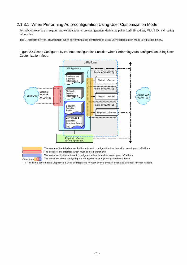
2.1.3.1 When Performing Auto-configuration Using User Customization ModeFor public networks that require auto-configuration or pre-configuration, decide the public LAN IP address, VLAN ID, and routinginformation.
The L-Platform network environment when performing auto-configuration using user customization mode is explained below.
Figure 2.4 Scope Configured by the Auto-configuration Function when Performing Auto-configuration Using UserCustomization Mode
- 26 -

Figure 2.5 Example Network Configuration of Blade Servers when Performing Auto-configuration Using UserCustomization Mode
Figure 2.6 Example Network Configuration of Rack Mount Servers when Performing Auto-configuration UsingUser Customization Mode
- 27 -
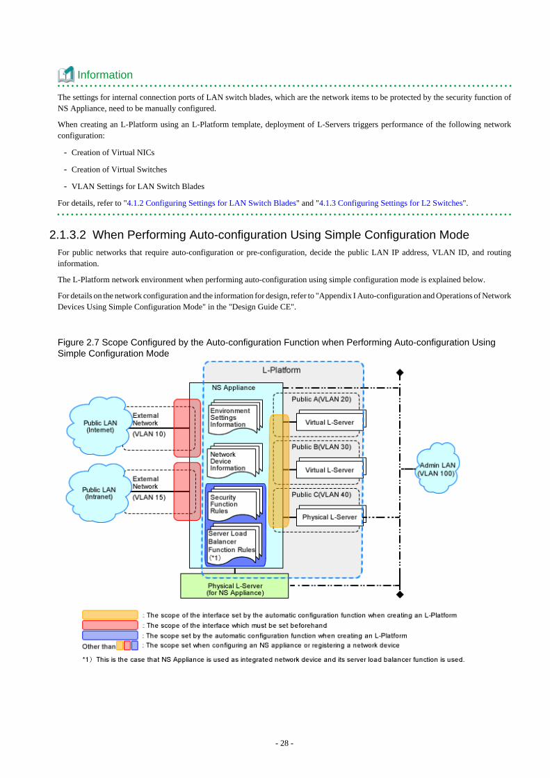
Information
The settings for internal connection ports of LAN switch blades, which are the network items to be protected by the security function ofNS Appliance, need to be manually configured.
When creating an L-Platform using an L-Platform template, deployment of L-Servers triggers performance of the following networkconfiguration:
- Creation of Virtual NICs
- Creation of Virtual Switches
- VLAN Settings for LAN Switch Blades
For details, refer to "4.1.2 Configuring Settings for LAN Switch Blades" and "4.1.3 Configuring Settings for L2 Switches".
2.1.3.2 When Performing Auto-configuration Using Simple Configuration ModeFor public networks that require auto-configuration or pre-configuration, decide the public LAN IP address, VLAN ID, and routinginformation.
The L-Platform network environment when performing auto-configuration using simple configuration mode is explained below.
For details on the network configuration and the information for design, refer to "Appendix I Auto-configuration and Operations of NetworkDevices Using Simple Configuration Mode" in the "Design Guide CE".
Figure 2.7 Scope Configured by the Auto-configuration Function when Performing Auto-configuration UsingSimple Configuration Mode
- 28 -

Figure 2.8 Example Network Configuration of Blade Servers when Performing Auto-configuration Using SimpleConfiguration Mode
Figure 2.9 Example Network Configuration of Rack Mount Servers when Performing Auto-configuration UsingSimple Configuration Mode
- 29 -
Information
The settings for internal connection ports of LAN switch blades, which are the network items to be protected by the security function ofNS Appliance, need to be manually configured.
When creating an L-Platform using an L-Platform template, deployment of L-Servers triggers performance of the following networkconfiguration:
- Creation of Virtual NICs
- Creation of Virtual Switches
- VLAN Settings for LAN Switch Blades
For details, refer to "4.1.2 Configuring Settings for LAN Switch Blades" and "4.1.3 Configuring Settings for L2 Switches".
2.1.4 Resource PoolsUse resource pools in order to deploy the following two resources:
- The resources used by the dedicated server for NS Appliances
- NS Appliances
Define the organization of the resource pools, according to the following guideline for creating resource pools.
- The resources used by the dedicated server for NS Appliances
- Image poolStore the cloning images for NS Option in a dedicated image pool to make them inaccessible to anyone except infrastructureadministrators, and isolate them from tenant administrators and tenant users.
- Server, storage, network, and address poolsAlthough the resources can be deployed in any of these pools, it is recommended to place them in the dedicated pool accessibleonly by infrastructure administrators so that it will be easy to monitor the consumption of the resources in that pool.
- NS Appliances
- Network poolRegister each NS Appliance as a network device and place it in the network pool for the tenant which will use it.
2.2 PreparationsThis section explains the preparations necessary for setup of NS Appliance.
The necessary preparations are as follows:
- Preparations for admin servers, admin clients, and storage
Use the same procedure as for ROR CE.For details, refer to "9.2 Defining Configuration Settings for Devices" and "9.3 Pre-configuring Devices" in the "Design Guide CE".
- Preparations for the network
The preparation necessary for the network is explained in "2.2.5 Preparations for the Network".
- Managed Servers
Necessary preparations for managed servers are explained in "2.2.6 Preparations for Managed Servers".
2.2.1 Required License ConfirmationConfirm that the CE licenses required for using NS Appliance are registered.
For details on how to confirm the CE licenses registered with the manager, refer to "Chapter 4 License Setup and Confirmation" in the"Setup Guide CE".
- 30 -
2.2.2 Preparations for NS ApplianceWhen using an NS Appliance as an integrated network device, perform preparations depending on the functions that will be used.
- When using the SSL accelerator function
Obtain the server certificate (PKCS#12 format) and CA certificate (PEM format) acquired from the certificate authority, from thetenant user.NS Appliance supports server certificates with up to 2,048-bit long keys and CA certificates with up to 4,096-bit long keys.
- When using an error page
The error page file (html file)When using simple configuration mode, it is recommended to create an error page response file using the sample error page responsefile (unmslb-default-slb.html).For details, refer to "C.4 Error Page Response File Operations".
2.2.3 Creating Definition FilesCreate the necessary definition files.
This section explains how to create the following definition files:
- Configuration information pre-definition file
Specify when using rack mount servers.
- Definition files combining ports of SAN storage
Create definition files combining ports of SAN storage.
- Network configuration information files
Create the network configuration information file necessary for registering NS Appliance as a network device.
- NS Appliance Pre-configuration File
Create the NS Appliance pre-configuration file which is necessary for pre-configuring the external network that is a prerequisite foruse of the auto-configuration function during L-Platform creation.
- Network Device Configuration File Management Function Definition
Define it when using the network device configuration file management functions.
- Configuration Files for Creating Dedicated Physical L-Servers for NS Appliance
Create the configuration file when creating a dedicated physical L-Server for NS Appliances using the rcxnetworkservice createcommand.
2.2.3.1 Configuration information pre-definition fileSpecify when using rack mount servers.
For details, refer to "7.1.6 Configuration when Creating a Physical L-Server without Specifying a Model Name in the L-Server Template"in the "Setup Guide CE".
2.2.3.2 Definition files combining ports of SAN storageCreate definition files combining ports of SAN storage.
For details, refer to "7.1 Creating Definition Files" in the "Setup Guide CE".
2.2.3.3 Network Configuration Information FilesCreate the network configuration information file necessary for registering NS Appliance as a network device.
In the network configuration information file, specify the information defined when "2.1.2 Designing the Network Environment".
- 31 -

For details on creating network configuration information files and their definition content, refer to "15.7 Network ConfigurationInformation" in the "Reference Guide (Command/XML) CE".
A tool for quickly creating network configuration information (XML definitions) is available on the FUJITSU Software ServerViewResource Orchestrator Web site. This tool makes it easy to create network configuration information (XML definitions).
When creating network configuration information files for NS Appliance, be sure to specify the following elements:
Admin IP address (Netdevice ip)
Specify an IPv4 address.
Netdevice subnetmask (Netdevice subnetmask)
Specify in the IPv4 format.
Device name (name) (Netdevice name)
Specify a character string containing up to 32 alphanumeric characters, periods ("."), and hyphens ("-").
Type (Type)
When using it as a firewall, specify "Firewall".
Specify "Firewall" and "SLB", when using it as an integrated network device.
Type of Appliance (ApplianceType)
Specify "virtual".
IP Address of Management Host (ManagementHost)
Specify the IP address of the dedicated server for NS Appliance in IPv4 format.
Vendor Name (Vendor)
Specify "Fujitsu".
Model Name (ModelName)
Specify "NSAppliance".
Community name (ReadCommunity)
Specify a character string containing up to 32 alphanumeric characters, underscores ("_"), and hyphens ("-").
Administrator Privileges (LoginInfo authority)
Specify "user".
Account (User)
Specify a character string containing up to 32 alphanumeric characters, underscores ("_"), and hyphens ("-").
Password (Password)
Specify a character string containing between 6 and 64 alphanumeric characters and symbols (!$%()_-~^[]:+,).
Administrator password (PrivilegedPassword)
Specify a character string containing between 6 and 64 alphanumeric characters and symbols (!$%()_-~^[]:+,).
Elements to Specify in the Network Configuration Information File for NS Appliances depending on the Admin LAN NetworkConfiguration of NS Appliances
VLAN IDs of Admin LANs (Netdevice vlanid)
For network configuration using the same VLAN ID (same network) as the admin LAN of dedicated servers for deployment ofNS Appliances, omit this element.For network configuration using different VLAN IDs from the admin LAN of dedicated servers for NS Appliances, specify theVLAN ID of the admin LAN of NS Appliances.
- 32 -
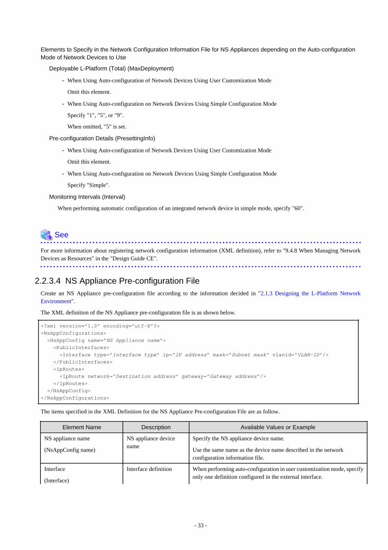
Elements to Specify in the Network Configuration Information File for NS Appliances depending on the Auto-configurationMode of Network Devices to Use
Deployable L-Platform (Total) (MaxDeployment)
- When Using Auto-configuration of Network Devices Using User Customization Mode
Omit this element.
- When Using Auto-configuration on Network Devices Using Simple Configuration Mode
Specify "1", "5", or "9".
When omitted, "5" is set.
Pre-configuration Details (PresettingInfo)
- When Using Auto-configuration of Network Devices Using User Customization Mode
Omit this element.
- When Using Auto-configuration on Network Devices Using Simple Configuration Mode
Specify "Simple".
Monitoring Intervals (Interval)
When performing automatic configuration of an integrated network device in simple mode, specify "60".
See
For more information about registering network configuration information (XML definition), refer to "9.4.8 When Managing NetworkDevices as Resources" in the "Design Guide CE".
2.2.3.4 NS Appliance Pre-configuration FileCreate an NS Appliance pre-configuration file according to the information decided in "2.1.3 Designing the L-Platform NetworkEnvironment".
The XML definition of the NS Appliance pre-configuration file is as shown below.
<?xml version="1.0" encoding="utf-8"?>
<NsAppConfigurations>
<NsAppConfig name="NS Appliance name"> <PublicInterfaces>
<Interface type="Interface type" ip="IP address" mask="Subnet mask" vlanid="VLAN-ID"/> </PublicInterfaces>
<IpRoutes>
<IpRoute network="Destination address" gateway="Gateway address"/> </IpRoutes>
</NsAppConfig>
</NsAppConfigurations>
The items specified in the XML Definition for the NS Appliance Pre-configuration File are as follow.
Element Name Description Available Values or Example
NS appliance name
(NsAppConfig name)
NS appliance devicename
Specify the NS appliance device name.
Use the same name as the device name described in the networkconfiguration information file.
Interface
(Interface)
Interface definition When performing auto-configuration in user customization mode, specifyonly one definition configured in the external interface.
- 33 -

Element Name Description Available Values or Example
When performing auto-configuration in simple configuration mode,specify the definition configured in the interface for the internet side andfor the intranet side respectively, based on the network design.
Interface type
(Interface type)
Type of interface Specify the interface type configured in the external interface of the NSappliance.
Specify one of the following, only when performing auto-configuration insimple configuration mode.
- Internet
- Intranet
IP address
(Interface ip)
IP address of interface Specify an IPv4 address.
Subnet mask
(Interface mask)
Subnet mask of interface
Subnet mask
Specify the subnet mask.
Specify the subnet mask using a value between 128.0.0.0 and255.255.255.252.
VLAN-ID
(Interface vlanid)
VLAN-ID of interface
VLAN-ID
Specify the VLAN-ID.
Specify an integer between 1 and 4094.
Route information
(IpRoute)
Route information Specify the route information.
Specify one or multiple sets of route information.
Destination address
(IpRoute network)
Network Address/MaskLength
Specify the address using the IPv4 prefix format.
When specifying it as the default gateway, specify "0.0.0.0/0".
Gateway Address
(IpRoute gateway)
Gateway Address Specify the gateway address.
Example
<?xml version="1.0" encoding="utf-8"?>
<NsAppConfigurations>
<NsAppConfig name="NS01">
<PublicInterfaces>
<Interface type="Internet" ip="192.168.10.10" mask="255.255.255.0" vlanid="10"/>
<Interface type="Intranet" ip="192.168.15.10" mask="255.255.255.0" vlanid="15"/>
</PublicInterfaces>
<IpRoutes>
<IpRoute network="0.0.0.0/0" gateway="192.168.10.1"/>
</IpRoutes>
</NsAppConfig>
</NsAppConfigurations>
2.2.3.5 Network Device Configuration File Management Function DefinitionDefine it when using the network device configuration file management functions.
When using an internal disk of a dedicated server for an NS Appliance, the network device file management functions make it easier torecover from server failure.
For details on the network device configuration file management functions, refer to the following:
- 34 -

- Usage method
"9.4.8.2 When Using the Network Device File Management Function" in the "Design Guide CE"
- Operation method
"10.2 Backup and Restoration of Network Devices" in the "Operation Guide CE"
When using the network device file management function, note the following points:
- The network device configuration file management function creates a temporary file in NS Appliances.
For this reason, do not create the following files in NS Appliances:
- ror-running-config.cli
- ror-startup-config.cli
- When performing the following on an NS Appliance, back up the network device configuration file using the rcxadm netdevicecfbackup command.
- Preparations for NS Appliances
- Pre-configuration of NS Appliances
For details on the rcxadm netdevice command, refer to "3.8 rcxadm netdevice" in the "Reference Guide (Command/XML) CE".
2.2.3.6 Configuration Files for Creating Dedicated Physical L-Servers for NS ApplianceCreate the configuration file when creating a dedicated physical L-Server for NS Appliances using the rcxnetworkservice create command.
It can be created using commands when the following conditions are satisfied. When the conditions are not met or when performingcreation using the GUI (operation from the ROR console), it is not necessary to create this file.
- When creating a dedicated server for NS appliances using SAN storage
- When using an admin LAN in which NIC1 and NIC2 are in a redundant configuration
Format
- State one item on each line as follows:
"item name" = value
- Be aware that character strings are case-sensitive.
- When omitting optional items, do not state the entire line.
- Save the file using the UTF-8 encoding format.
Configuration Items
Specify the following information:
Item Name Description Expected Values
FOLDER Destination resource folder
The folder to which the L-Server will be deployed
To specify the level, use the following format:
Resource_folder_name/Resource_folder_name
Tenant_folder_name/Resource_folder_name
Resource_folder_name/Tenant_folder_name
LSERVER L-Server name The name of the L-Server to be deployed
IMAGE Image A cloning image for NS Option to use for deployment
- 35 -
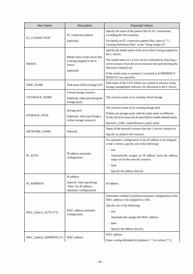
Item Name Description Expected Values
FC_CONNECTIONFC connection pattern
(optional)
Specify the name of the pattern file for FC connections,excluding the file extension.
For details on FC connection pattern files, refer to "7.1Creating Definition Files" in the "Setup Guide CE".
MODEL
Model name of the server thatis being assigned to the L-Server
(optional)
Specify the model name of the server that is being assigned tothe L-Server.
The model name of a server can be confirmed by selecting aserver resource from the server resource tree and checking the[Resource Details] tab.
If the model name is omitted, it is treated as if PRIMERGYBX924 S2 was specified.
DISK_NAME Disk name of the existing LUNDisk name of the LUN which was created in advance usingstorage management software, for allocation to the L-Server
VSTORAGE_NAME
Virtual storage resource
(Optional, when specifying thestorage pool)
The resource name of an existing virtual storage
STORAGE_POOL
Storage pool
(Optional, when specifying avirtual storage resource)
The resource name of an existing storage pool
If there are storage pools with the same name on differentlevels, the level must also be specified to enable identification.
Resource_folder_name/Resource_pool_name
NETWORK_NAME NetworkName of the network resource that the L-Server connects to
Specify an admin LAN resource.
IP_AUTOIP address automaticconfiguration
For automatic configuration of the IP address to be assignedto the L-Server, specify one of the following:
- true
Automatically assigns an IP address from the addressrange set for the network resource.
- false
Specify the address directly.
IP_ADDRESS
IP address
(Specify when specifying"false" for IP addressautomatic configuration)
IP address
MAC_[index]_AUTO (*1)MAC address automaticconfiguration
Determines whether to perform automatic configuration of theMAC address to be assigned to a NIC.
Specify one of the following:
- true
Automatically assigns the MAC address.
- false
Specify the address directly.
MAC_[index]_ADDRESS (*1) MAC addressMAC address
Enter a string delimited by hyphens ("-") or colons (":").
- 36 -

Item Name Description Expected Values
(Specify when specifying"false" for MAC addressautomatic configuration)
MAC_[index]_RESOURCE(*1)
MAC address set resource
(Specify when specifying"true" for MAC addressautomatic configurationNot usable when specifying aMAC address pool)
Address set resource from which the MAC address is assigned
MAC_[index]_POOL (*1)
MAC address pool
(Specify when specifying"true" for MAC addressautomatic configurationNot usable, when specifying aMAC address set resource)
Address pool from which the MAC address is assigned
HBA HBA count The number of HBAs to allocate to the L-Server
WWN_[index]_AUTO (*2)
WWN automaticconfiguration
(Specify the same number asthe HBA count)
Determines whether to allocate a WWN automatically.
Specify one of the following:
- true
Automatic configuration
- false
Manual configuration
WWN_[index] (*2)
WWN
(Specify when specifying"false" for WWN automaticconfiguration)
WWN
Specify the WWN in colon (":") delimited form.
WWN_[index]_RESOURCE(*2)
WWN address set resource
(Specify when specifying"true" for WWN automaticconfigurationNot usable, when specifying aWWN address pool)
Address set resource from which the WWN is assigned
WWN_[index]_POOL (*2)
WWN address pool
(Specify when specifying"true" for WWN automaticconfigurationNot usable, when specifying aWWN address set resource)
Address pool from which the WWN is assigned
ADDRESS_POOL Address pool
Address pool to allocate to the L-Server
If there are storage pools with the same name on differentlevels, the level must also be specified to enable identification.
To specify the level, use the following format:
Resource_folder_name/Resource_pool_name
REDUNDANCY RedundancySpecify the server redundancy to be assigned to the L-Server.
Specify one of the following:
- 37 -
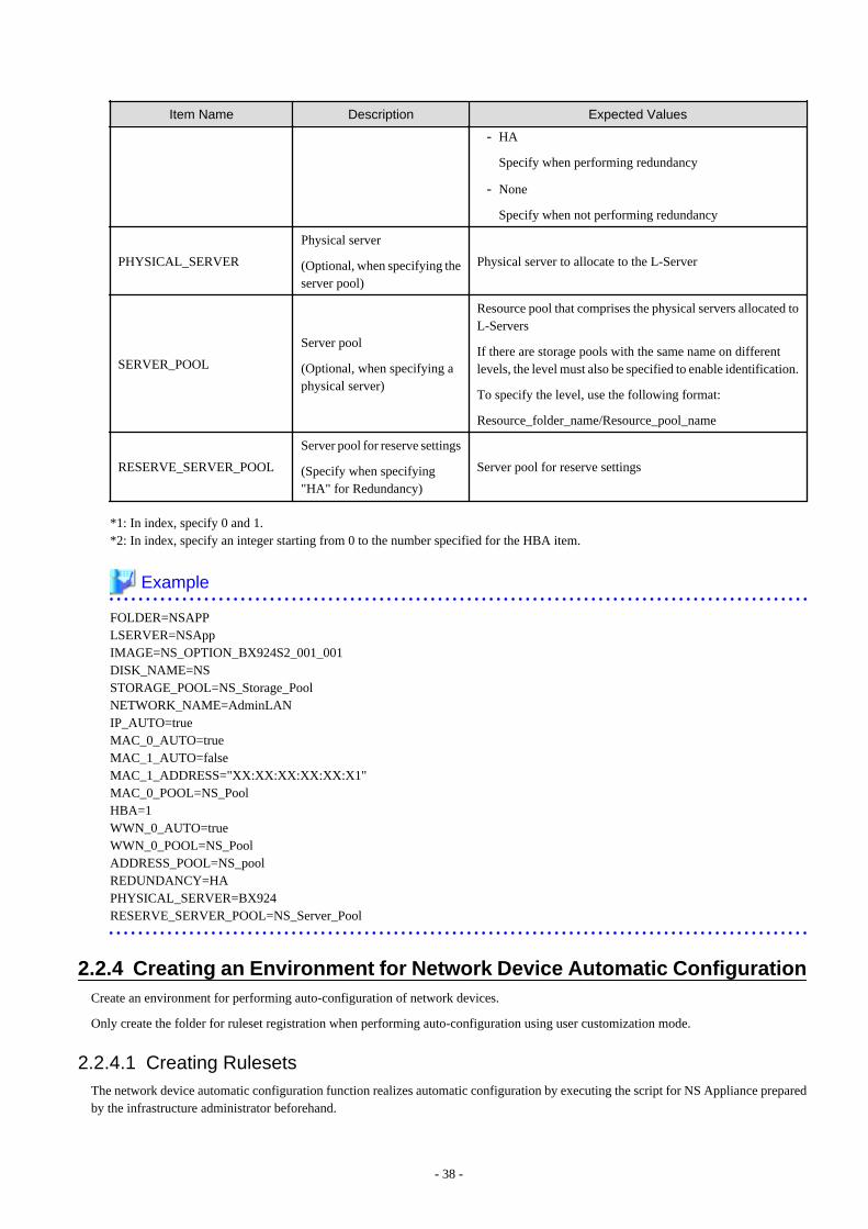
Item Name Description Expected Values
- HA
Specify when performing redundancy
- None
Specify when not performing redundancy
PHYSICAL_SERVER
Physical server
(Optional, when specifying theserver pool)
Physical server to allocate to the L-Server
SERVER_POOL
Server pool
(Optional, when specifying aphysical server)
Resource pool that comprises the physical servers allocated toL-Servers
If there are storage pools with the same name on differentlevels, the level must also be specified to enable identification.
To specify the level, use the following format:
Resource_folder_name/Resource_pool_name
RESERVE_SERVER_POOL
Server pool for reserve settings
(Specify when specifying"HA" for Redundancy)
Server pool for reserve settings
*1: In index, specify 0 and 1.*2: In index, specify an integer starting from 0 to the number specified for the HBA item.
Example
FOLDER=NSAPPLSERVER=NSAppIMAGE=NS_OPTION_BX924S2_001_001DISK_NAME=NSSTORAGE_POOL=NS_Storage_PoolNETWORK_NAME=AdminLANIP_AUTO=trueMAC_0_AUTO=trueMAC_1_AUTO=falseMAC_1_ADDRESS="XX:XX:XX:XX:XX:X1"MAC_0_POOL=NS_PoolHBA=1WWN_0_AUTO=trueWWN_0_POOL=NS_PoolADDRESS_POOL=NS_poolREDUNDANCY=HAPHYSICAL_SERVER=BX924RESERVE_SERVER_POOL=NS_Server_Pool
2.2.4 Creating an Environment for Network Device Automatic ConfigurationCreate an environment for performing auto-configuration of network devices.
Only create the folder for ruleset registration when performing auto-configuration using user customization mode.
2.2.4.1 Creating RulesetsThe network device automatic configuration function realizes automatic configuration by executing the script for NS Appliance preparedby the infrastructure administrator beforehand.
- 38 -
To configure different settings for individual services being provided, register each pattern as a rule for management.
This management unit is referred to as the ruleset.
- This operation is not necessary when using sample scripts provided with Resource Orchestrator.
- When creating a ruleset, it is recommended to use the sample scripts provided with Resource Orchestrator.
For details, refer to "Appendix F Preparing for Automatic Configuration and Operation of Network Devices" and "Appendix G SampleScript for Automatic Configuration and Operation of Network Devices" in the "Design Guide CE".
2.2.4.2 Creating a Folder for Registering Rulesets and Registering RulesetsCreate a folder for registering rulesets and register rulesets.
1. Create a folder for registering scripts, etc. for each ruleset.
[Windows Manager]Installation_folder\SVROR\Manager\etc\scripts\Fujitsu\NSAppliance\rulesets\ruleset_name\
[Linux Manager]/etc/opt/FJSVrcvmr/scripts/Fujitsu/NSAppliance/rulesets/ruleset_name/
2. Store the files that comprise the rulesets in the folder created above.
Information
- Specify the folder name of "ruleset name" using up to 32 characters, including alphanumeric characters, underscores ("_"), and hyphens("-"). This name should start with an alphabetical character.Set a unique name for the folder name of "ruleset name", excluding the following folders in which sample scripts are registered.
[Windows Manager]Installation_folder\SVROR\Manager\etc\scripts\
[Linux Manager]/etc/opt/FJSVrcvmr/scripts/
- When using the sample scripts provided by NS Option, the following operations will be performed during the operations explainedin "3.7 Registering NS Appliances as Resources".
- Creating a Folder for Registering Rulesets
- Copying of Sample Scripts into Rulesets
The sample script for the system configuration using only a firewall is copied.
- When using a sample script or when creating a ruleset using a sample script, change the ruleset name from the one in the sample scriptto a different name.
- Ruleset names are determined by the registered folder name.
- Specify the ruleset name that was changed to the ruleset name (Ruleset name) in the parameter file (for scripts).
For details on parameter files (for scripts), refer to "15.16 Parameter Files (for Scripts)" in the "Reference Guide (Command/XML)CE".
- When using a sample script (SLB_with_SSL-ACC--NSApp1) or when creating a ruleset based on a sample script, SSLv3/tls1.0 isenabled for the SSL protocol being used. When the SSL protocol to be used is limited to SSLv3 or tls1.0, edit the command file usingthe following procedure:
- File to edit
ipcom_modify_cmd2.cli
- How to edit
Under "rule ssl-accel", add the following definitions:
- 39 -
- When limiting to SSLv3, specify "protocol.ssl3".
- When limiting to tls1.0, specify "protocol.tls1".
Example
The "rule ssl-accel definition" when limited to tls1.0 is as follows:
rule ssl-accel server 1%%SLB-Netdevice_ID%%0
server-address %Slb-VServer-IPv4% %Slb-VServer-SSLPort%
cert %Slb-Certificate%
connection-limit %Slb-Access-Limit%
name Server_%Slb-VServer-IPv4%
protocol tls1
cipher-suites -LOW -SSL2
unsafe-renegotiation disable
http-proxy redirect auto
http-proxy secure-cookie
!
2.2.4.3 Creating a Network Device Interface Configuration FileSpecify the network resource name and IP address corresponding to the interfaces of NS Appliances during auto-configuration of networkdevices.
For details on network device interface configuration files, refer to "15.17 Network Device Interface Configuration File" in the "ReferenceGuide (Command/XML) CE".
2.2.5 Preparations for the NetworkThis section explains the preparations for setting up the network.
In order to use NS Appliance on a network, it is necessary to perform the following preparations:
- Preparations for LAN Switch Blades
- Preparations for L2 Switches
2.2.5.1 Preparations for LAN Switch BladesThis operation is necessary when using LAN switch blades.
For preparations for LAN switch blades, define and configure the following information:
- VLAN ID of the admin LAN used to communicate with the admin server
Point
Configure the VLAN for the internal connection ports to connect to the dedicated servers for NS Appliances for creating NS Appliancesas follows:
- For Physical L-Servers
- When using the same VLAN for the physical L-Server and NS Appliance
Untagged-VLAN is configured automatically.
- When using different VLANs for the physical L-Server and NS Appliance
- For the VLAN used by physical L-Servers, Untagged-VLAN is configured automatically.
- For the VLAN used by NS Appliances, configure a Tagged-VLAN.
- 40 -

- For Physical servers
- When using the same VLAN for the physical server and NS Appliances
Configure an untagged VLAN.
- When using different VLANs for the physical server and NS Appliances
- For the VLANs used by physical servers, configure Untagged VLANs.
- For the VLAN used by NS Appliances, configure a Tagged-VLAN.
- IP address of the managed network device for management
- SNMP community name
- Administrator information (user name, password, and privileged administrator password)
- SNMP trap destination
For configuration information details and configuration instructions, refer to LAN switch blade manuals.
Figure 2.10 Configuration Targets of LAN Switch Blades and Network Configuration after Completing Preparationwhen Performing Auto-configuration Using User Customization Mode
- 41 -
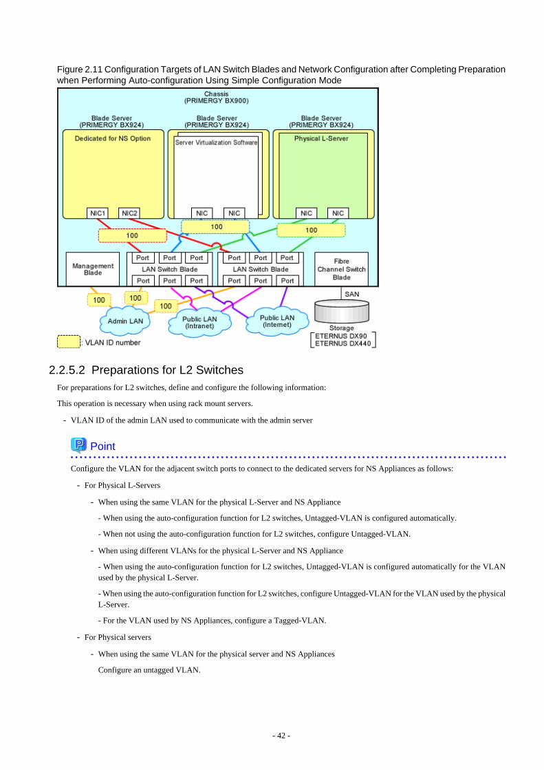
Figure 2.11 Configuration Targets of LAN Switch Blades and Network Configuration after Completing Preparationwhen Performing Auto-configuration Using Simple Configuration Mode
2.2.5.2 Preparations for L2 SwitchesFor preparations for L2 switches, define and configure the following information:
This operation is necessary when using rack mount servers.
- VLAN ID of the admin LAN used to communicate with the admin server
Point
Configure the VLAN for the adjacent switch ports to connect to the dedicated servers for NS Appliances as follows:
- For Physical L-Servers
- When using the same VLAN for the physical L-Server and NS Appliance
- When using the auto-configuration function for L2 switches, Untagged-VLAN is configured automatically.
- When not using the auto-configuration function for L2 switches, configure Untagged-VLAN.
- When using different VLANs for the physical L-Server and NS Appliance
- When using the auto-configuration function for L2 switches, Untagged-VLAN is configured automatically for the VLANused by the physical L-Server.
- When using the auto-configuration function for L2 switches, configure Untagged-VLAN for the VLAN used by the physicalL-Server.
- For the VLAN used by NS Appliances, configure a Tagged-VLAN.
- For Physical servers
- When using the same VLAN for the physical server and NS Appliances
Configure an untagged VLAN.
- 42 -

- When using different VLANs for the physical server and NS Appliances
- For the VLANs used by physical servers, configure Untagged VLANs.
- For the VLAN used by NS Appliances, configure a Tagged-VLAN.
- IP address of the managed network device for management
- SNMP community name
- Administrator information (user name, password, and privileged administrator password)
- SNMP trap destination
For configuration information details and configuration instructions, refer to L2 switch manuals.
Figure 2.12 Configuration Targets of L2 Switches and Network Configuration after Completing Preparation whenPerforming Auto-configuration Using User Customization Mode
- 43 -
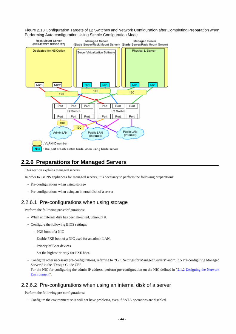
Figure 2.13 Configuration Targets of L2 Switches and Network Configuration after Completing Preparation whenPerforming Auto-configuration Using Simple Configuration Mode
2.2.6 Preparations for Managed ServersThis section explains managed servers.
In order to use NS appliances for managed servers, it is necessary to perform the following preparations:
- Pre-configurations when using storage
- Pre-configurations when using an internal disk of a server
2.2.6.1 Pre-configurations when using storagePerform the following pre-configurations:
- When an internal disk has been mounted, unmount it.
- Configure the following BIOS settings:
- PXE boot of a NIC
Enable PXE boot of a NIC used for an admin LAN.
- Priority of Boot devices
Set the highest priority for PXE boot.
- Configure other necessary pre-configurations, referring to "9.2.5 Settings for Managed Servers" and "9.3.5 Pre-configuring ManagedServers" in the "Design Guide CE". For the NIC for configuring the admin IP address, perform pre-configuration on the NIC defined in "2.1.2 Designing the NetworkEnvironment".
2.2.6.2 Pre-configurations when using an internal disk of a serverPerform the following pre-configurations:
- Configure the environment so it will not have problems, even if SATA operations are disabled.
- 44 -
- When a Fibre Channel card is mounted on the server, disconnect it from SAN storage.
- Configure RAID for internal disks.For details on how to configure RAID, refer to the manual for the internal disk.
- Configure the following BIOS settings:
- PXE boot of a NIC
Enable PXE boot of a NIC used for an admin LAN.
- Priority of Boot devices
Set the highest priority for PXE boot.
- SATA operations
Disable SATA operations.
- Configure other necessary pre-configurations, referring to "9.2.5 Settings for Managed Servers" and "9.3.5 Pre-configuring ManagedServers" in the "Design Guide CE". For the NIC for configuring the admin IP address, perform pre-configuration on the NIC defined in "2.1.2 Designing the NetworkEnvironment".
- 45 -

Chapter 3 SetupThis chapter explains the setup for using NS Appliance.
In order to use NS Appliance, the following setup operations must be performed:
- Confirming Resource Registration States
- Registering Resources to Resource Pools
- Creating Dedicated Servers for NS Appliance
- License Setup
- Creating NS Appliances
- Configuring NS Appliances
- Registering NS Appliances as Resources
3.1 Confirming Resource Registration StatesOn the ROR console, confirm that the following resources associated with NS Appliance have been registered:
- VIOM
- Storage
When using an internal disk, NS appliance does not require storage resources.
- Managed Servers (Blade Servers)
- Chassis
- Server Blade
For the server blades used for a dedicated server for NS Appliance, ensure they are registered with a redundant NIC configurationfor the admin LAN.
- LAN Switch Blade
- Managed Servers (Rack Mount Servers)
- Rack Mount Server
For the rack mount server used for a dedicated server for NS Appliance, ensure it is registered with a redundant NIC configurationfor the admin LAN.
- L2 Switch
If these resources have not been registered, register them.
For details on how to register resources, refer to "Chapter 5 Registering Resources" in the "User's Guide for Infrastructure Administrators(Resource Management) CE".
If there are any mistakes in the settings of the registered resources, modify the resources.
For details on how to change resources, refer to "Chapter 7 Changing Resources" in the "User's Guide for Infrastructure Administrators(Resource Management) CE".
3.2 Registering Resources to Resource PoolsIf the resources necessary for the system on which NS Appliances are to be deployed have not been registered in resource pools, registerthem in the resource pools. Registration destinations are those defined in "2.1.4 Resource Pools".
Registering Server Resources
Register the servers to which physical L-Servers (for NS Appliance) are deployed to in the server pool.
- 46 -
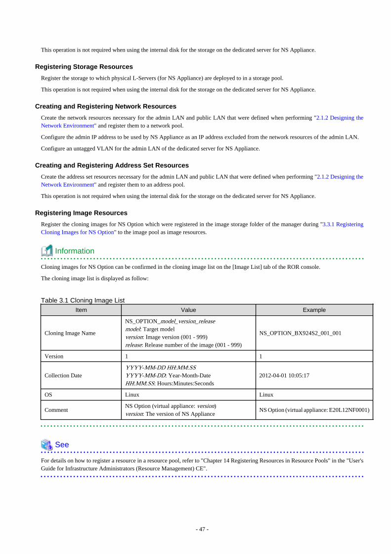
This operation is not required when using the internal disk for the storage on the dedicated server for NS Appliance.
Registering Storage Resources
Register the storage to which physical L-Servers (for NS Appliance) are deployed to in a storage pool.
This operation is not required when using the internal disk for the storage on the dedicated server for NS Appliance.
Creating and Registering Network Resources
Create the network resources necessary for the admin LAN and public LAN that were defined when performing "2.1.2 Designing theNetwork Environment" and register them to a network pool.
Configure the admin IP address to be used by NS Appliance as an IP address excluded from the network resources of the admin LAN.
Configure an untagged VLAN for the admin LAN of the dedicated server for NS Appliance.
Creating and Registering Address Set Resources
Create the address set resources necessary for the admin LAN and public LAN that were defined when performing "2.1.2 Designing theNetwork Environment" and register them to an address pool.
This operation is not required when using the internal disk for the storage on the dedicated server for NS Appliance.
Registering Image Resources
Register the cloning images for NS Option which were registered in the image storage folder of the manager during "3.3.1 RegisteringCloning Images for NS Option" to the image pool as image resources.
Information
Cloning images for NS Option can be confirmed in the cloning image list on the [Image List] tab of the ROR console.
The cloning image list is displayed as follow:
Table 3.1 Cloning Image List
Item Value Example
Cloning Image Name
NS_OPTION_model_version_releasemodel: Target modelversion: Image version (001 - 999)release: Release number of the image (001 - 999)
NS_OPTION_BX924S2_001_001
Version 1 1
Collection DateYYYY-MM-DD HH:MM:SSYYYY-MM-DD: Year-Month-DateHH:MM:SS: Hours:Minutes:Seconds
2012-04-01 10:05:17
OS Linux Linux
CommentNS Option (virtual appliance: version)version: The version of NS Appliance
NS Option (virtual appliance: E20L12NF0001)
See
For details on how to register a resource in a resource pool, refer to "Chapter 14 Registering Resources in Resource Pools" in the "User'sGuide for Infrastructure Administrators (Resource Management) CE".
- 47 -
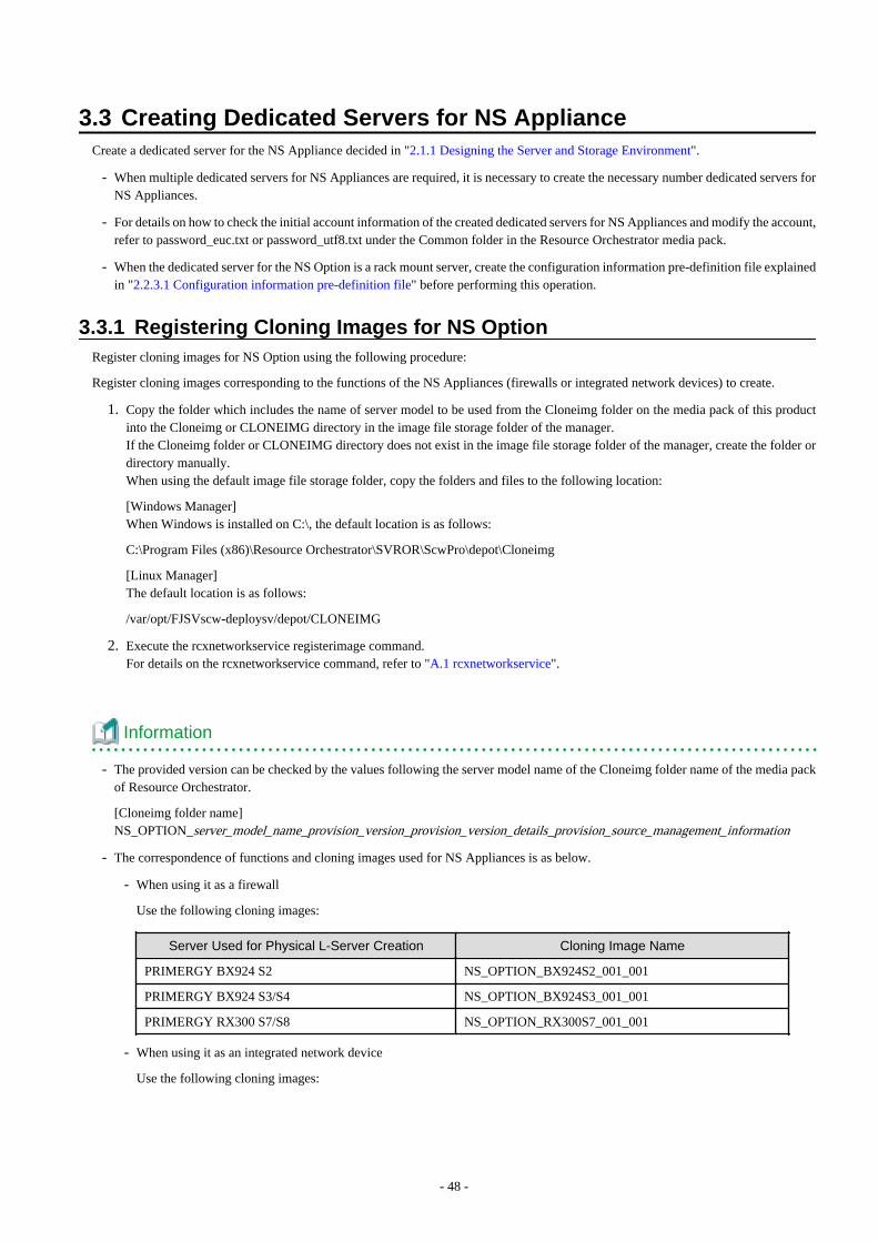
3.3 Creating Dedicated Servers for NS ApplianceCreate a dedicated server for the NS Appliance decided in "2.1.1 Designing the Server and Storage Environment".
- When multiple dedicated servers for NS Appliances are required, it is necessary to create the necessary number dedicated servers forNS Appliances.
- For details on how to check the initial account information of the created dedicated servers for NS Appliances and modify the account,refer to password_euc.txt or password_utf8.txt under the Common folder in the Resource Orchestrator media pack.
- When the dedicated server for the NS Option is a rack mount server, create the configuration information pre-definition file explainedin "2.2.3.1 Configuration information pre-definition file" before performing this operation.
3.3.1 Registering Cloning Images for NS OptionRegister cloning images for NS Option using the following procedure:
Register cloning images corresponding to the functions of the NS Appliances (firewalls or integrated network devices) to create.
1. Copy the folder which includes the name of server model to be used from the Cloneimg folder on the media pack of this productinto the Cloneimg or CLONEIMG directory in the image file storage folder of the manager.If the Cloneimg folder or CLONEIMG directory does not exist in the image file storage folder of the manager, create the folder ordirectory manually.When using the default image file storage folder, copy the folders and files to the following location:
[Windows Manager]When Windows is installed on C:\, the default location is as follows:
C:\Program Files (x86)\Resource Orchestrator\SVROR\ScwPro\depot\Cloneimg
[Linux Manager]The default location is as follows:
/var/opt/FJSVscw-deploysv/depot/CLONEIMG
2. Execute the rcxnetworkservice registerimage command.For details on the rcxnetworkservice command, refer to "A.1 rcxnetworkservice".
Information
- The provided version can be checked by the values following the server model name of the Cloneimg folder name of the media packof Resource Orchestrator.
[Cloneimg folder name]NS_OPTION_server_model_name_provision_version_provision_version_details_provision_source_management_information
- The correspondence of functions and cloning images used for NS Appliances is as below.
- When using it as a firewall
Use the following cloning images:
Server Used for Physical L-Server Creation Cloning Image Name
PRIMERGY BX924 S2 NS_OPTION_BX924S2_001_001
PRIMERGY BX924 S3/S4 NS_OPTION_BX924S3_001_001
PRIMERGY RX300 S7/S8 NS_OPTION_RX300S7_001_001
- When using it as an integrated network device
Use the following cloning images:
- 48 -
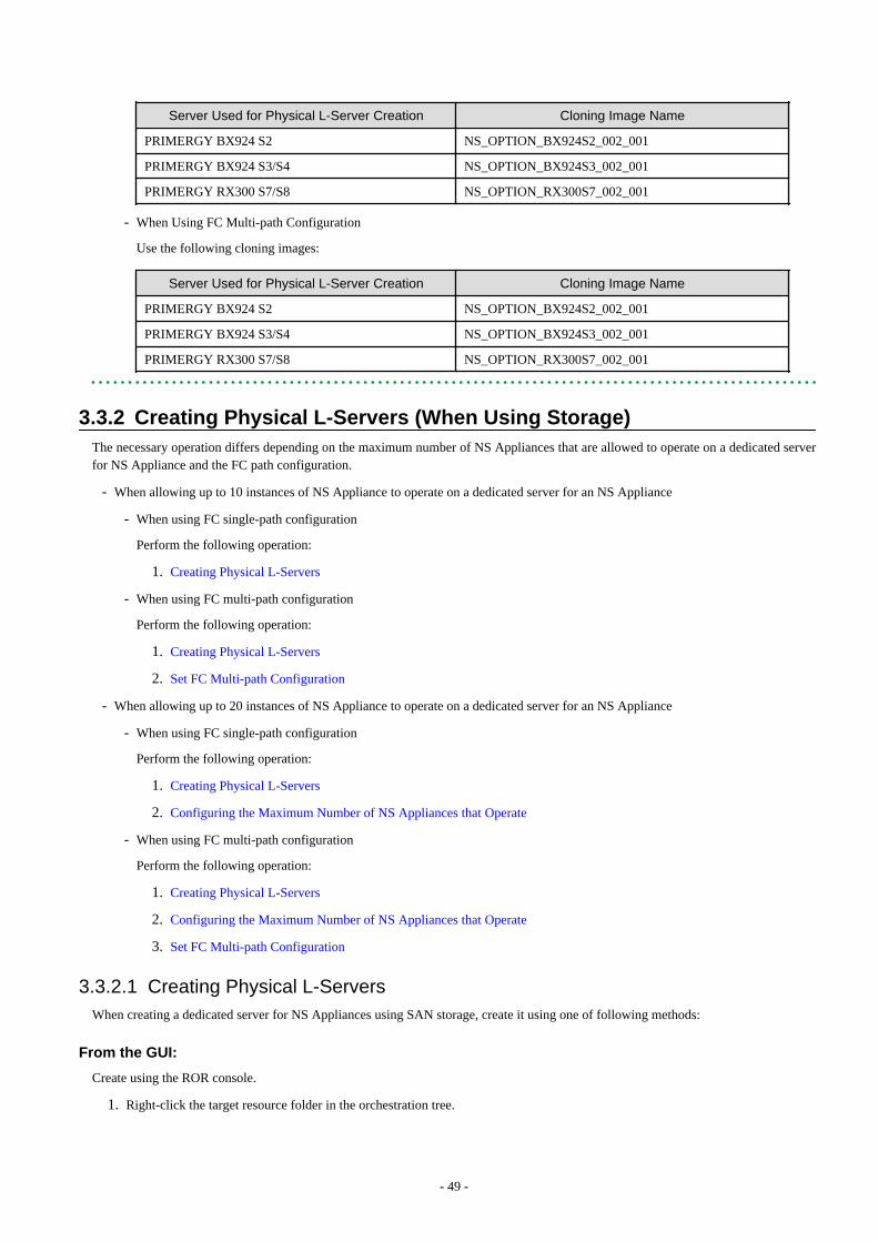
Server Used for Physical L-Server Creation Cloning Image Name
PRIMERGY BX924 S2 NS_OPTION_BX924S2_002_001
PRIMERGY BX924 S3/S4 NS_OPTION_BX924S3_002_001
PRIMERGY RX300 S7/S8 NS_OPTION_RX300S7_002_001
- When Using FC Multi-path Configuration
Use the following cloning images:
Server Used for Physical L-Server Creation Cloning Image Name
PRIMERGY BX924 S2 NS_OPTION_BX924S2_002_001
PRIMERGY BX924 S3/S4 NS_OPTION_BX924S3_002_001
PRIMERGY RX300 S7/S8 NS_OPTION_RX300S7_002_001
3.3.2 Creating Physical L-Servers (When Using Storage)The necessary operation differs depending on the maximum number of NS Appliances that are allowed to operate on a dedicated serverfor NS Appliance and the FC path configuration.
- When allowing up to 10 instances of NS Appliance to operate on a dedicated server for an NS Appliance
- When using FC single-path configuration
Perform the following operation:
1. Creating Physical L-Servers
- When using FC multi-path configuration
Perform the following operation:
1. Creating Physical L-Servers
2. Set FC Multi-path Configuration
- When allowing up to 20 instances of NS Appliance to operate on a dedicated server for an NS Appliance
- When using FC single-path configuration
Perform the following operation:
1. Creating Physical L-Servers
2. Configuring the Maximum Number of NS Appliances that Operate
- When using FC multi-path configuration
Perform the following operation:
1. Creating Physical L-Servers
2. Configuring the Maximum Number of NS Appliances that Operate
3. Set FC Multi-path Configuration
3.3.2.1 Creating Physical L-ServersWhen creating a dedicated server for NS Appliances using SAN storage, create it using one of following methods:
From the GUI:
Create using the ROR console.
1. Right-click the target resource folder in the orchestration tree.
- 49 -

2. Select [Create]-[L-Server] from the displayed menu.
3. The [Create an L-Server] dialog is displayed.
4. Configure each item using the relevant tabs.
5. Click [OK].The L-Server is created.
The values to specify when creating the physical L-Server for NS Appliance are explained below:
For the items not explained here, specify arbitrary values.
Table 3.2 Specified Values on the [General] Tab
Item Specified Value
Template Specify "None".
Server type Specify "Physical".
ImageSpecify "Cloning image for NS Option".Specify the cloning image for the server model to be used.
Resource allocation Uncheck the checkbox.
Network (NIC)Select only the admin LAN.Configure admin LAN NICs in a redundant configuration as explained in "2.1.2 Designingthe Network Environment".
Table 3.3 Specified Values on the [Server] Tab
Item Specified Value
Server Specification Methods Select "Model" and specify server models supported by NS Option.
Resource release Uncheck the checkbox.
FC path Specify "Single path mode".
Boot Mode Specify "Default".
Table 3.4 Specified Values on the [Disk] Tab
Item Specified Value
Disk type Specify "SAN".
Disk
- When allowing up to 10 instances of NS Appliance to operate
Specify "100G*1".
- When allowing up to 20 instances of NS Appliance to operate
Specify "175G*1"
Table 3.5 Specified Values on the [Network] Tab
Item Specified Value
NIC/Network
Select only the admin LAN.
Configure admin LAN NICs in a redundant configuration as explained in "2.1.2 Designingthe Network Environment".
IP address (Optional) Specify the IP address for the admin LAN.
For details on specified items and how to create physical L-Servers, refer to "16.2 Creation of Physical L-Servers Using Parameters" inthe "User's Guide for Infrastructure Administrators (Resource Management) CE".
- 50 -
From the Command-line:
Create a physical L-Server for NS Appliance using the rcxnetworkservice lserver command.
L-Servers can be created using commands when the following conditions are satisfied.
If these conditions are not satisfied, create them using the GUI.
- When creating a dedicated server for NS Appliances using SAN storage
- When using an admin LAN in which NIC1 and NIC2 are in a redundant configuration
For details on this command, refer to "A.1 rcxnetworkservice".
3.3.2.2 Configuring the Maximum Number of NS Appliances that OperateA physical L-Server for NS Appliance is created using the configuration that allows up to 10 NS Appliances to operate.
To allow up to 20 NS Appliances to operate, it is necessary to change the configuration of the physical L-Server for NS Appliance usingthe rcxnetworkservice appext command.
For details on this command, refer to "A.1 rcxnetworkservice".
3.3.2.3 Set FC Multi-path ConfigurationA physical L-Server for NS Appliance is created using an FC single path configuration.
To perform an FC multi-path configuration of a physical L-Server for NS Appliance, use the following procedure:
1. Stop the physical L-Server for NS Appliance.For details on how to stop physical L-Servers, refer to "17.1.2 Stopping an L-Server" in the "User's Guide for InfrastructureAdministrators (Resource Management) CE".
2. Right-click the target physical L-Server in the orchestration tree.
3. In the displayed menu, select [Modify]-[Modify Specification].
4. In the displayed menu, select [Indicates the settings for when the server starts]-[FC path] and uncheck the single path mode checkbox.
5. Click the [OK] button.
6. Start a physical L-Server for NS Appliance.For details on how to start physical L-Servers, refer to "17.1.1 Starting an L-Server" in the "User's Guide for InfrastructureAdministrators (Resource Management) CE".
7. Execute the rcxnetworkservice fcctl command.Executing this command restarts the physical L-Server for NS Appliance.For details on this command, refer to "A.1 rcxnetworkservice".
3.3.3 Creating Physical Servers (When Using the Internal Disk of a Server)The necessary operation differs depending on the maximum number of NS Appliances that are allowed to operate on a dedicated serverfor NS Appliance.
- When allowing up to 10 instances of NS Appliance to operate on a dedicated server for an NS Appliance
Perform the following operation:
1. Create Physical Servers
- When allowing up to 20 instances of NS Appliance to operate on a dedicated server for an NS Appliance
Perform the following operation:
1. Create Physical Servers
2. Configure the Maximum Number of NS Appliances that Operate
- 51 -
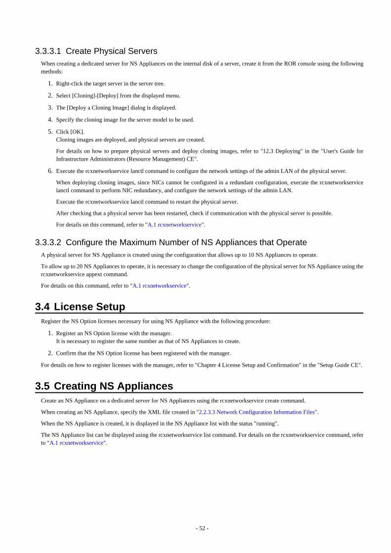
3.3.3.1 Create Physical ServersWhen creating a dedicated server for NS Appliances on the internal disk of a server, create it from the ROR console using the followingmethods:
1. Right-click the target server in the server tree.
2. Select [Cloning]-[Deploy] from the displayed menu.
3. The [Deploy a Cloning Image] dialog is displayed.
4. Specify the cloning image for the server model to be used.
5. Click [OK].Cloning images are deployed, and physical servers are created.
For details on how to prepare physical servers and deploy cloning images, refer to "12.3 Deploying" in the "User's Guide forInfrastructure Administrators (Resource Management) CE".
6. Execute the rcxnetworkservice lanctl command to configure the network settings of the admin LAN of the physical server.
When deploying cloning images, since NICs cannot be configured in a redundant configuration, execute the rcxnetworkservicelanctl command to perform NIC redundancy, and configure the network settings of the admin LAN.
Execute the rcxnetworkservice lanctl command to restart the physical server.
After checking that a physical server has been restarted, check if communication with the physical server is possible.
For details on this command, refer to "A.1 rcxnetworkservice".
3.3.3.2 Configure the Maximum Number of NS Appliances that OperateA physical server for NS Appliance is created using the configuration that allows up to 10 NS Appliances to operate.
To allow up to 20 NS Appliances to operate, it is necessary to change the configuration of the physical server for NS Appliance using thercxnetworkservice appext command.
For details on this command, refer to "A.1 rcxnetworkservice".
3.4 License SetupRegister the NS Option licenses necessary for using NS Appliance with the following procedure:
1. Register an NS Option license with the manager.It is necessary to register the same number as that of NS Appliances to create.
2. Confirm that the NS Option license has been registered with the manager.
For details on how to register licenses with the manager, refer to "Chapter 4 License Setup and Confirmation" in the "Setup Guide CE".
3.5 Creating NS AppliancesCreate an NS Appliance on a dedicated server for NS Appliances using the rcxnetworkservice create command.
When creating an NS Appliance, specify the XML file created in "2.2.3.3 Network Configuration Information Files".
When the NS Appliance is created, it is displayed in the NS Appliance list with the status "running".
The NS Appliance list can be displayed using the rcxnetworkservice list command. For details on the rcxnetworkservice command, referto "A.1 rcxnetworkservice".
- 52 -

Figure 3.1 Example of Network Configuration after Creation of NS Appliance when Using User CustomizationMode (Blade Servers)
Figure 3.2 Example of Network Configuration after Creation of NS Appliance when Using User CustomizationMode (Rack Mount Servers)
- 53 -

Figure 3.3 Example of Network Configuration after Creation of NS Appliance when Using Simple ConfigurationMode (Blade Servers)
Figure 3.4 Example of Network Configuration after Creation of NS Appliance when Using Simple ConfigurationMode (Rack Mount Servers)
- 54 -
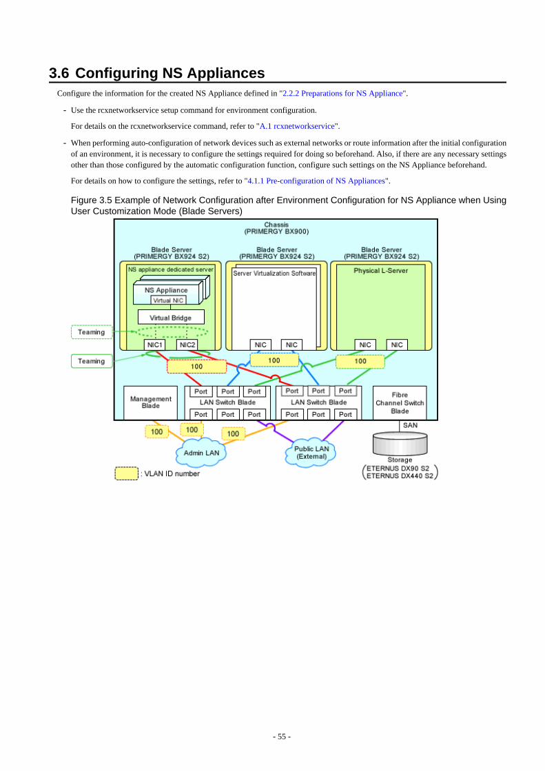
3.6 Configuring NS AppliancesConfigure the information for the created NS Appliance defined in "2.2.2 Preparations for NS Appliance".
- Use the rcxnetworkservice setup command for environment configuration.
For details on the rcxnetworkservice command, refer to "A.1 rcxnetworkservice".
- When performing auto-configuration of network devices such as external networks or route information after the initial configurationof an environment, it is necessary to configure the settings required for doing so beforehand. Also, if there are any necessary settingsother than those configured by the automatic configuration function, configure such settings on the NS Appliance beforehand.
For details on how to configure the settings, refer to "4.1.1 Pre-configuration of NS Appliances".
Figure 3.5 Example of Network Configuration after Environment Configuration for NS Appliance when UsingUser Customization Mode (Blade Servers)
- 55 -
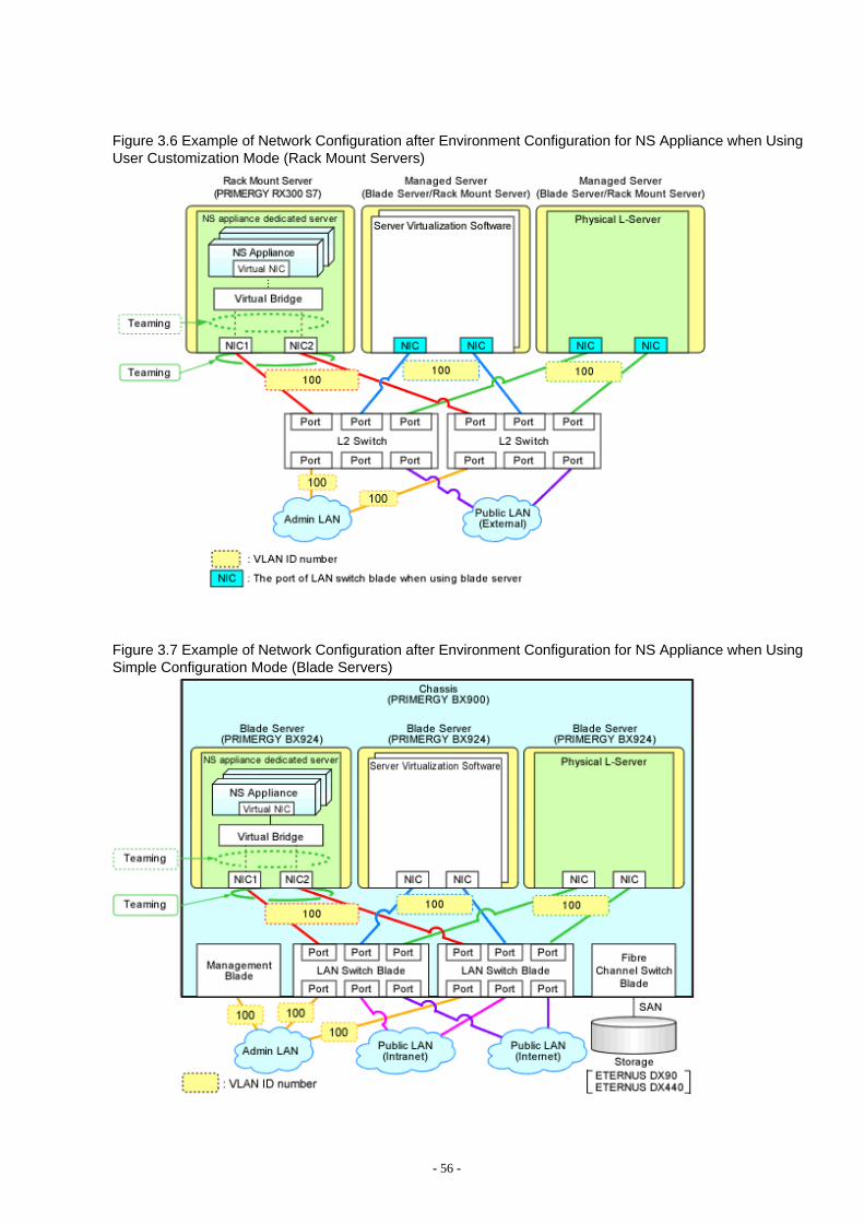
Figure 3.6 Example of Network Configuration after Environment Configuration for NS Appliance when UsingUser Customization Mode (Rack Mount Servers)
Figure 3.7 Example of Network Configuration after Environment Configuration for NS Appliance when UsingSimple Configuration Mode (Blade Servers)
- 56 -
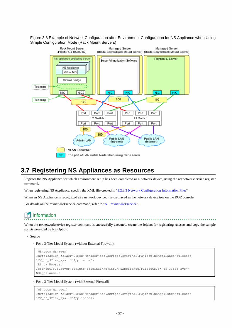
Figure 3.8 Example of Network Configuration after Environment Configuration for NS Appliance when UsingSimple Configuration Mode (Rack Mount Servers)
3.7 Registering NS Appliances as ResourcesRegister the NS Appliance for which environment setup has been completed as a network device, using the rcxnetworkservice registercommand.
When registering NS Appliance, specify the XML file created in "2.2.3.3 Network Configuration Information Files".
When an NS Appliance is recognized as a network device, it is displayed in the network device tree on the ROR console.
For details on the rcxnetworkservice command, refer to "A.1 rcxnetworkservice".
Information
When the rcxnetworkservice register command is successfully executed, create the folders for registering rulesets and copy the samplescripts provided by NS Option.
- Source
- For a 3-Tier Model System (without External Firewall)
[Windows Manager]
Installation_folder\SVROR\Manager\etc\scripts\original\Fujitsu\NSAppliance\rulesets\FW_of_3Tier_sys--NSAppliance2\
[Linux Manager]
/etc/opt/FJSVrcvmr/scripts/original/Fujitsu/NSAppliance/rulesets/FW_of_3Tier_sys--
NSAppliance2/
- For a 3-Tier Model System (with External Firewall)
[Windows Manager]
Installation_folder\SVROR\Manager\etc\scripts\original\Fujitsu\NSAppliance\rulesets\FW_of_3Tier_sys--NSAppliance1\
- 57 -

[Linux Manager]
/etc/opt/FJSVrcvmr/scripts/original/Fujitsu/NSAppliance/rulesets/FW_of_3Tier_sys--
NSAppliance1/
- Destination
- For a 3-Tier Model System (without External Firewall)
[Windows Manager]
Installation_folder\SVROR\Manager\etc\scripts\Fujitsu\NSAppliance\rulesets\FW_of_3Tier_sys--NSAppliance2\
[Linux Manager]
/etc/opt/FJSVrcvmr/scripts/Fujitsu/NSAppliance/rulesets/FW_of_3Tier_sys--NSAppliance2/
- For a 3-Tier Model System (with External Firewall)
[Windows Manager]
Installation_folder\SVROR\Manager\etc\scripts\Fujitsu\NSAppliance\rulesets\FW_of_3Tier_sys--NSAppliance1\
[Linux Manager]
/etc/opt/FJSVrcvmr/scripts/Fujitsu/NSAppliance/rulesets/FW_of_3Tier_sys--NSAppliance1/
The default model configuration for a sample script is shown below:
Figure 3.9 Default Model Configuration for a Sample Script (Blade Servers)
- 58 -
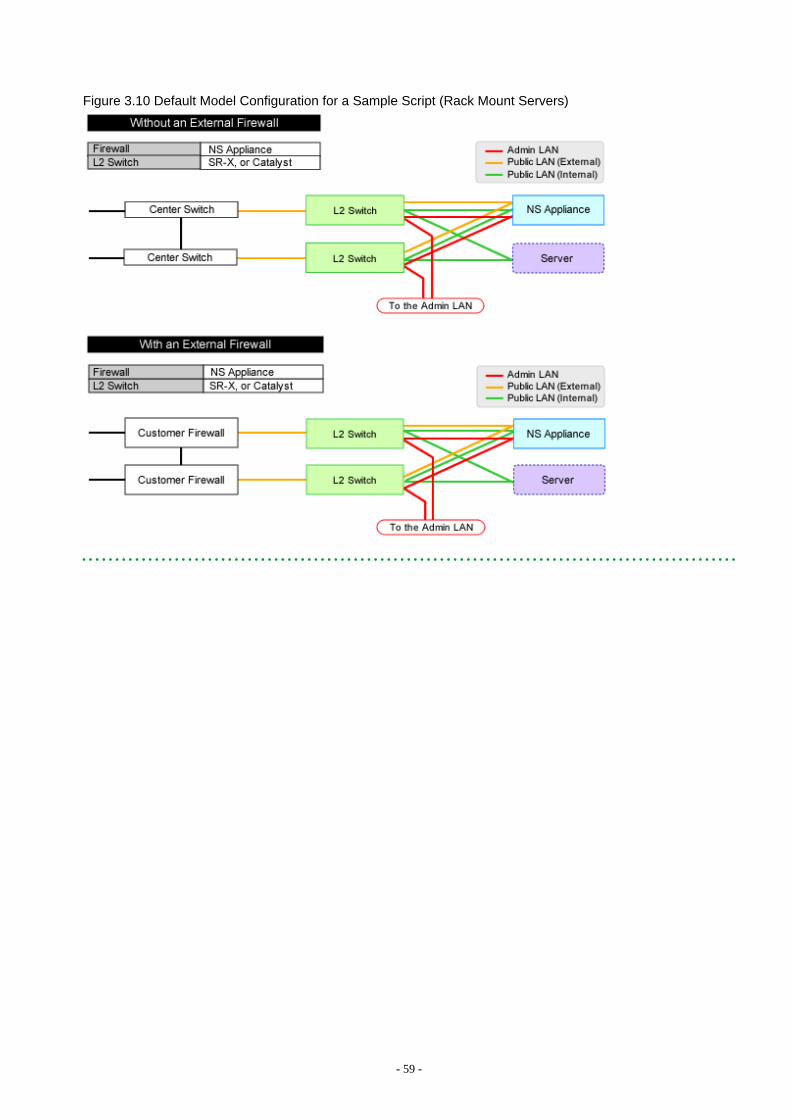
Figure 3.10 Default Model Configuration for a Sample Script (Rack Mount Servers)
- 59 -

Chapter 4 OperationThis chapter explains how to operate NS Appliances.
4.1 Operation of NS AppliancesThis section explains how to operate NS Appliances.
4.1.1 Pre-configuration of NS AppliancesIn order to use NS Appliances, it is necessary to configure the settings and store the certificates in advance.
It is not necessary to configure the account information to access to the necessary NS Appliances in advance for the following cases, asthe information is configured when configuring NS Appliances (when executing the rcxnetworkservice setup command or thercxnetworkservice deploy command).
- When using the network device file management function
- When performing auto-configuration of network devices
- When performing operations of network devices
When Performing Auto-configuration and Operation of NS Appliances Using User Customization Mode
Check the specification of scripts for automatic configuration, and configure the pre-definition of the NS Appliance (the pre-configurationof an NS Appliance necessary to execute scripts).Register the certificates and the error page response files required for automatic configuration of the server load balancer in the NSAppliance.
When Performing Auto-configuration and operation of NS Appliances Using Simple Configuration Mode
Use the NS Appliance pre-configuration file created in preparations to perform configuration using the rcxnetworkservice preconfigcommand.
For details on the procedure, refer to "Appendix C Pre-configuration Method for NS Appliances".
When using the network device file management function, back up the file after this operation is completed. For details on the networkdevice file management function, refer to "10.2 Backup and Restoration of Network Devices" in the "Operation Guide CE".
4.1.2 Configuring Settings for LAN Switch BladesConfigure the VLAN IDs of all network resources used on the L-Platform on the internal connection ports of the LAN switch bladesconnected to the NIC of the dedicated server for NS Appliances.
This operation is necessary when using blade servers.
- From the GUI:
1. Right-click the server the dedicated server for NS Appliance was created on from the ROR console server resource tree.
2. In the displayed menu, select [Modify]-[Network Settings].
3. In the displayed [Network Settings] window, configure the VLAN IDs to use.
- Command
Execute VLAN configuration of switch blade using the rcxadm nsoptctl addvlan command.For details on the rcxadm nsoptctl command, refer to "A.2 rcxadm nsoptctl".
For details, refer to "5.4.4.2 Configuring VLANs on Internal Connection Ports" in the "User's Guide for Infrastructure Administrators(Resource Management) CE".
- 60 -
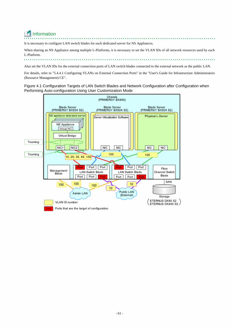
Information
It is necessary to configure LAN switch blades for each dedicated server for NS Appliances.
When sharing an NS Appliance among multiple L-Platforms, it is necessary to set the VLAN IDs of all network resources used by eachL-Platform.
Also set the VLAN IDs for the external connection ports of LAN switch blades connected to the external network as the public LAN.
For details, refer to "5.4.4.1 Configuring VLANs on External Connection Ports" in the "User's Guide for Infrastructure Administrators(Resource Management) CE".
Figure 4.1 Configuration Targets of LAN Switch Blades and Network Configuration after Configuration whenPerforming Auto-configuration Using User Customization Mode
- 61 -
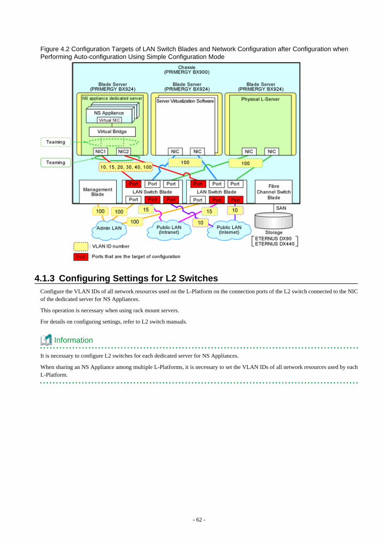
Figure 4.2 Configuration Targets of LAN Switch Blades and Network Configuration after Configuration whenPerforming Auto-configuration Using Simple Configuration Mode
4.1.3 Configuring Settings for L2 SwitchesConfigure the VLAN IDs of all network resources used on the L-Platform on the connection ports of the L2 switch connected to the NICof the dedicated server for NS Appliances.
This operation is necessary when using rack mount servers.
For details on configuring settings, refer to L2 switch manuals.
Information
It is necessary to configure L2 switches for each dedicated server for NS Appliances.
When sharing an NS Appliance among multiple L-Platforms, it is necessary to set the VLAN IDs of all network resources used by eachL-Platform.
- 62 -
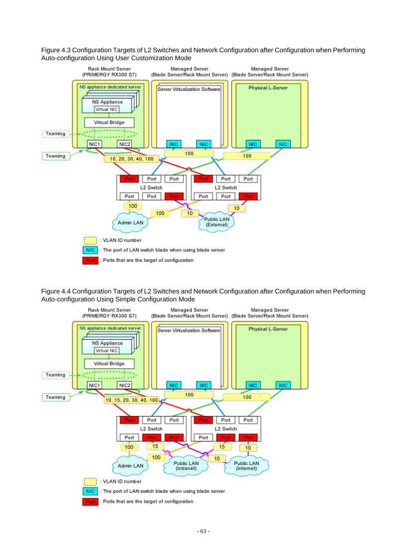
Figure 4.3 Configuration Targets of L2 Switches and Network Configuration after Configuration when PerformingAuto-configuration Using User Customization Mode
Figure 4.4 Configuration Targets of L2 Switches and Network Configuration after Configuration when PerformingAuto-configuration Using Simple Configuration Mode
- 63 -
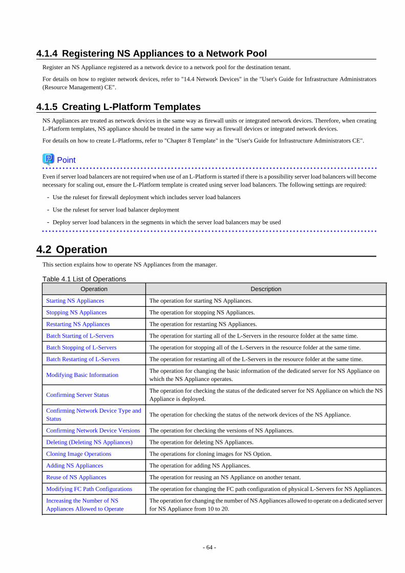
4.1.4 Registering NS Appliances to a Network PoolRegister an NS Appliance registered as a network device to a network pool for the destination tenant.
For details on how to register network devices, refer to "14.4 Network Devices" in the "User's Guide for Infrastructure Administrators(Resource Management) CE".
4.1.5 Creating L-Platform TemplatesNS Appliances are treated as network devices in the same way as firewall units or integrated network devices. Therefore, when creatingL-Platform templates, NS appliance should be treated in the same way as firewall devices or integrated network devices.
For details on how to create L-Platforms, refer to "Chapter 8 Template" in the "User's Guide for Infrastructure Administrators CE".
Point
Even if server load balancers are not required when use of an L-Platform is started if there is a possibility server load balancers will becomenecessary for scaling out, ensure the L-Platform template is created using server load balancers. The following settings are required:
- Use the ruleset for firewall deployment which includes server load balancers
- Use the ruleset for server load balancer deployment
- Deploy server load balancers in the segments in which the server load balancers may be used
4.2 OperationThis section explains how to operate NS Appliances from the manager.
Table 4.1 List of Operations
Operation Description
Starting NS Appliances The operation for starting NS Appliances.
Stopping NS Appliances The operation for stopping NS Appliances.
Restarting NS Appliances The operation for restarting NS Appliances.
Batch Starting of L-Servers The operation for starting all of the L-Servers in the resource folder at the same time.
Batch Stopping of L-Servers The operation for stopping all of the L-Servers in the resource folder at the same time.
Batch Restarting of L-Servers The operation for restarting all of the L-Servers in the resource folder at the same time.
Modifying Basic InformationThe operation for changing the basic information of the dedicated server for NS Appliance onwhich the NS Appliance operates.
Confirming Server StatusThe operation for checking the status of the dedicated server for NS Appliance on which the NSAppliance is deployed.
Confirming Network Device Type andStatus
The operation for checking the status of the network devices of the NS Appliance.
Confirming Network Device Versions The operation for checking the versions of NS Appliances.
Deleting (Deleting NS Appliances) The operation for deleting NS Appliances.
Cloning Image Operations The operations for cloning images for NS Option.
Adding NS Appliances The operation for adding NS Appliances.
Reuse of NS Appliances The operation for reusing an NS Appliance on another tenant.
Modifying FC Path Configurations The operation for changing the FC path configuration of physical L-Servers for NS Appliances.
Increasing the Number of NSAppliances Allowed to Operate
The operation for changing the number of NS Appliances allowed to operate on a dedicated serverfor NS Appliance from 10 to 20.
- 64 -
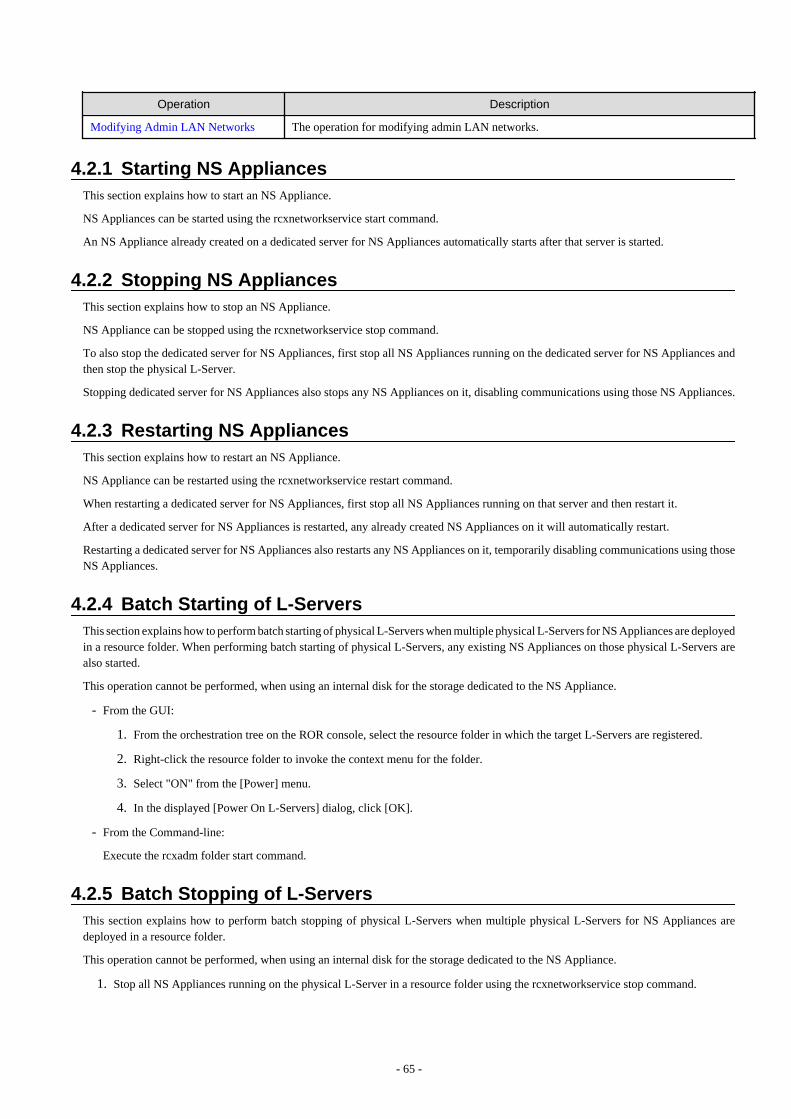
Operation Description
Modifying Admin LAN Networks The operation for modifying admin LAN networks.
4.2.1 Starting NS AppliancesThis section explains how to start an NS Appliance.
NS Appliances can be started using the rcxnetworkservice start command.
An NS Appliance already created on a dedicated server for NS Appliances automatically starts after that server is started.
4.2.2 Stopping NS AppliancesThis section explains how to stop an NS Appliance.
NS Appliance can be stopped using the rcxnetworkservice stop command.
To also stop the dedicated server for NS Appliances, first stop all NS Appliances running on the dedicated server for NS Appliances andthen stop the physical L-Server.
Stopping dedicated server for NS Appliances also stops any NS Appliances on it, disabling communications using those NS Appliances.
4.2.3 Restarting NS AppliancesThis section explains how to restart an NS Appliance.
NS Appliance can be restarted using the rcxnetworkservice restart command.
When restarting a dedicated server for NS Appliances, first stop all NS Appliances running on that server and then restart it.
After a dedicated server for NS Appliances is restarted, any already created NS Appliances on it will automatically restart.
Restarting a dedicated server for NS Appliances also restarts any NS Appliances on it, temporarily disabling communications using thoseNS Appliances.
4.2.4 Batch Starting of L-ServersThis section explains how to perform batch starting of physical L-Servers when multiple physical L-Servers for NS Appliances are deployedin a resource folder. When performing batch starting of physical L-Servers, any existing NS Appliances on those physical L-Servers arealso started.
This operation cannot be performed, when using an internal disk for the storage dedicated to the NS Appliance.
- From the GUI:
1. From the orchestration tree on the ROR console, select the resource folder in which the target L-Servers are registered.
2. Right-click the resource folder to invoke the context menu for the folder.
3. Select "ON" from the [Power] menu.
4. In the displayed [Power On L-Servers] dialog, click [OK].
- From the Command-line:
Execute the rcxadm folder start command.
4.2.5 Batch Stopping of L-ServersThis section explains how to perform batch stopping of physical L-Servers when multiple physical L-Servers for NS Appliances aredeployed in a resource folder.
This operation cannot be performed, when using an internal disk for the storage dedicated to the NS Appliance.
1. Stop all NS Appliances running on the physical L-Server in a resource folder using the rcxnetworkservice stop command.
- 65 -

2. Stop all L-Servers in a resource folder.
- From the GUI:
a. From the orchestration tree on the ROR console, select the resource folder in which the target physical L-Servers areregistered.
b. Right-click the resource folder to invoke the context menu for the folder.
c. Select "OFF" from the [Power] menu.
d. In the displayed [Power OFF L-Servers] dialog, click [OK].
- From the Command-line:
Execute the rcxadm folder stop command.
Stopping a physical L-Server also stops any NS Appliances on it, disabling communications using those NS Appliances.
4.2.6 Batch Restarting of L-ServersThis section explains how to perform batch restart of physical L-Servers when multiple physical L-Servers for NS Appliances are deployedin a resource folder. When performing batch restarting of physical L-Servers, any existing NS Appliances on those physical L-Servers arealso started.
This operation cannot be performed, when using an internal disk for the storage dedicated to the NS Appliance.
1. Stop all NS Appliances running on the physical L-Server in a resource folder using the rcxnetworkservice stop command.
2. Restart all L-Servers in a resource folder.
- From the GUI:
a. From the orchestration tree on the ROR console, select the resource folder in which the target physical L-Servers areregistered.
b. Right-click the resource folder to invoke the context menu for the folder.
c. Select "Reboot" from the [Power] menu.
d. In the displayed [Reboot L-Servers] dialog, click [OK].
- From the Command-line:
Execute the rcxadm folder restart command.
Restarting a physical L-Server also restarts any NS Appliances on it, temporarily disabling communications using those NS Appliances.
4.2.7 Modifying Basic InformationThis section explains the operation for changing the basic information of physical L-Servers on which NS Appliances operate.
This operation cannot be performed, when using an internal disk for the storage dedicated to the NS Appliance.
Basic Information that can be Modified
It is possible to modify the following information for physical L-Servers on which NS Appliances operate:
- L-Server Name
- Label
- Comment
Note
Do not modify any basic information other than the above.
If other information is modified, proper operation cannot be guaranteed.
- 66 -
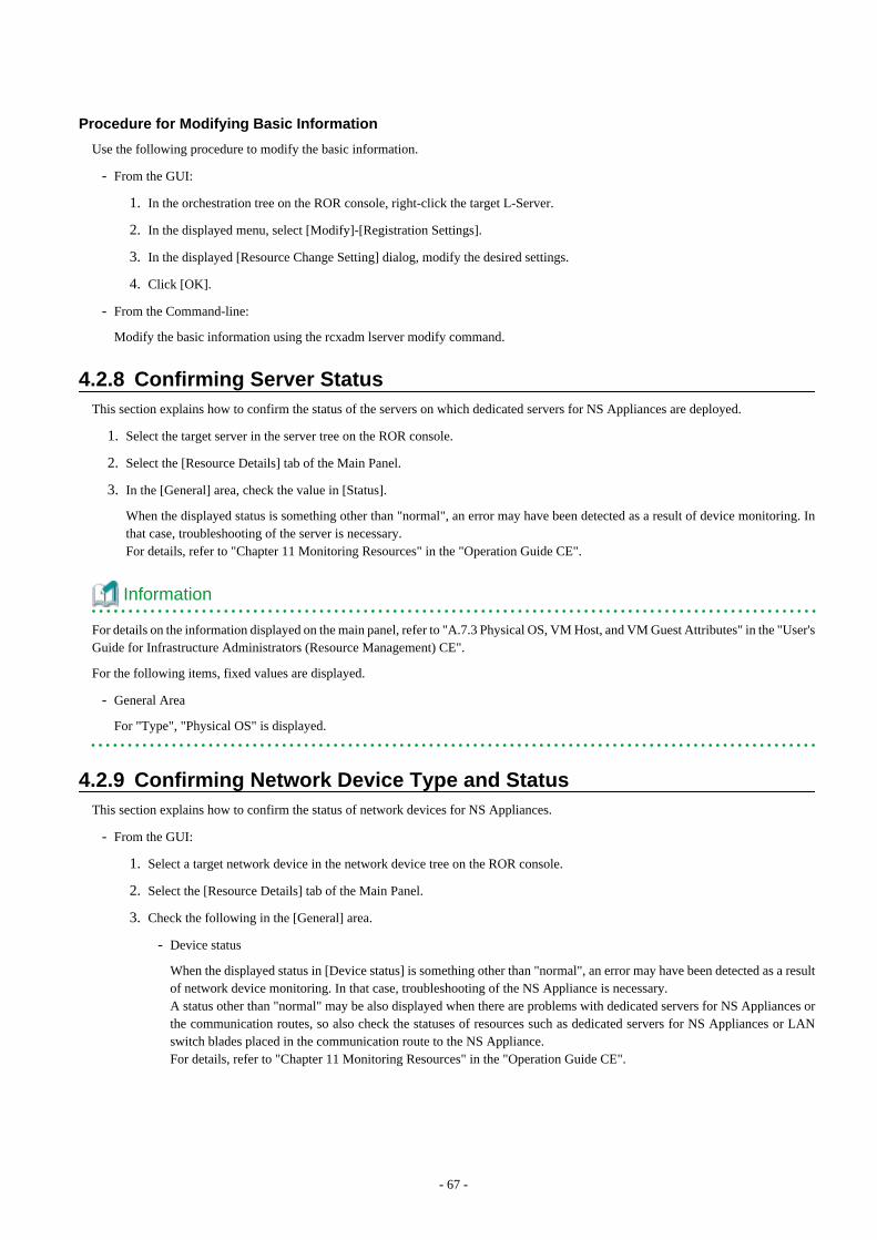
Procedure for Modifying Basic Information
Use the following procedure to modify the basic information.
- From the GUI:
1. In the orchestration tree on the ROR console, right-click the target L-Server.
2. In the displayed menu, select [Modify]-[Registration Settings].
3. In the displayed [Resource Change Setting] dialog, modify the desired settings.
4. Click [OK].
- From the Command-line:
Modify the basic information using the rcxadm lserver modify command.
4.2.8 Confirming Server StatusThis section explains how to confirm the status of the servers on which dedicated servers for NS Appliances are deployed.
1. Select the target server in the server tree on the ROR console.
2. Select the [Resource Details] tab of the Main Panel.
3. In the [General] area, check the value in [Status].
When the displayed status is something other than "normal", an error may have been detected as a result of device monitoring. Inthat case, troubleshooting of the server is necessary.For details, refer to "Chapter 11 Monitoring Resources" in the "Operation Guide CE".
Information
For details on the information displayed on the main panel, refer to "A.7.3 Physical OS, VM Host, and VM Guest Attributes" in the "User'sGuide for Infrastructure Administrators (Resource Management) CE".
For the following items, fixed values are displayed.
- General Area
For "Type", "Physical OS" is displayed.
4.2.9 Confirming Network Device Type and StatusThis section explains how to confirm the status of network devices for NS Appliances.
- From the GUI:
1. Select a target network device in the network device tree on the ROR console.
2. Select the [Resource Details] tab of the Main Panel.
3. Check the following in the [General] area.
- Device status
When the displayed status in [Device status] is something other than "normal", an error may have been detected as a resultof network device monitoring. In that case, troubleshooting of the NS Appliance is necessary.A status other than "normal" may be also displayed when there are problems with dedicated servers for NS Appliances orthe communication routes, so also check the statuses of resources such as dedicated servers for NS Appliances or LANswitch blades placed in the communication route to the NS Appliance.For details, refer to "Chapter 11 Monitoring Resources" in the "Operation Guide CE".
- 67 -
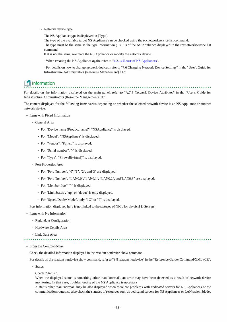
- Network device type
The NS Appliance type is displayed in [Type].The type of the available target NS Appliance can be checked using the rcxnetworkservice list command.The type must be the same as the type information (TYPE) of the NS Appliance displayed in the rcxnetworkservice listcommand.If it is not the same, re-create the NS Appliance or modify the network device.
- When creating the NS Appliance again, refer to "4.2.14 Reuse of NS Appliances".
- For details on how to change network devices, refer to "7.6 Changing Network Device Settings" in the "User's Guide forInfrastructure Administrators (Resource Management) CE".
Information
For details on the information displayed on the main panel, refer to "A.7.5 Network Device Attributes" in the "User's Guide forInfrastructure Administrators (Resource Management) CE".
The content displayed for the following items varies depending on whether the selected network device is an NS Appliance or anothernetwork device.
- Items with Fixed Information
- General Area
- For "Device name (Product name)", "NSAppliance" is displayed.
- For "Model", "NSAppliance" is displayed.
- For "Vendor", "Fujitsu" is displayed.
- For "Serial number", "-" is displayed.
- For "Type", "Firewall(virtual)" is displayed.
- Port Properties Area
- For "Port Number", "0","1", "2", and"3" are displayed.
- For "Port Number", "LAN0.0","LAN0.1", "LAN0.2", and"LAN0.3" are displayed.
- For "Member Port", "-" is displayed.
- For "Link Status", "up" or "down" is only displayed.
- For "Speed/DuplexMode", only "1G" or "0" is displayed.
Port information displayed here is not linked to the statuses of NICs for physical L-Servers.
- Items with No Information
- Redundant Configuration
- Hardware Details Area
- Link Data Area
- From the Command-line:
Check the detailed information displayed in the rcxadm netdevice show command.
For details on the rcxadm netdevice show command, refer to "3.8 rcxadm netdevice" in the "Reference Guide (Command/XML) CE".
- Status
Check "Status:".When the displayed status is something other than "normal", an error may have been detected as a result of network devicemonitoring. In that case, troubleshooting of the NS Appliance is necessary.A status other than "normal" may be also displayed when there are problems with dedicated servers for NS Appliances or thecommunication routes, so also check the statuses of resources such as dedicated servers for NS Appliances or LAN switch blades
- 68 -
placed in the communication route to the NS Appliance.For details, refer to "Chapter 11 Monitoring Resources" in the "Operation Guide CE".
- Network device type
The type of the NS Appliance is displayed in "NetdeviceTypes:".The type of the available target NS Appliance can be checked using the rcxnetworkservice list command.The type must be the same as the type information (TYPE) of the NS Appliance displayed in the rcxnetworkservice list command.If it is not the same, re-create the NS Appliance or modify the network device.
- When creating the NS Appliance again, refer to "4.2.14 Reuse of NS Appliances".
- For details on how to change network devices, refer to "7.6 Changing Network Device Settings" in the "User's Guide forInfrastructure Administrators (Resource Management) CE".
4.2.10 Confirming Network Device VersionsThis section explains how to check the versions of NS Appliances used as network devices.
- From the GUI:
1. Select a target network device in the network device tree on the ROR console.
2. Select the [Resource Details] tab of the Main Panel.
3. Check the value in [Firmware versions] in the [General] area.
- From the Command-line:
Check the firmware versions of the detailed information displayed in the rcxadm netdevice show command.
For details on the rcxadm netdevice show command, refer to "3.8 rcxadm netdevice" in the "Reference Guide (Command/XML) CE".
Information
The available functions can be checked using the NS Appliance version.
- For firewalls
E20L12 NF0103 or later
- For integrated network devices
E20L21 NF0201 or later
4.2.11 Deleting (Deleting NS Appliances)This section explains how to delete NS Appliances.
1. Confirm that the NS Appliance to be deleted is not being used on the L-Platform.Execute the rcxadm netdevice show command. If the line for "AllocatedResources[XXX]:" is blank, the corresponding NS Applianceis not being used on the L-Platform.When the NS Appliance is being used, request release of the L-Platform by the tenant administrator or the tenant user using thetarget L-Platform.The tenant administrator or tenant user requests release of the L-Platform, and after infrastructure administrator approves the requestthe L-Platform can be released.For details on the rcxadm netdevice show command, refer to "3.8 rcxadm netdevice" in the "Reference Guide (Command/XML)CE".
2. Unregister the network device resource for the NS Appliance from the network pool.For details on how to unregister network devices for NS Appliances from a network pool, refer to "19.4 Unregistration" in the"User's Guide for Infrastructure Administrators (Resource Management) CE".
3. Unregister the network device resource for NS Appliance from a resource pool using the rcxnetworkservice unregister command.
- 69 -

4. Stop the NS Appliance using the rcxnetworkservice stop command.
5. Delete the NS Appliance using the rcxnetworkservice delete command.
4.2.12 Cloning Image OperationsThis section explains operations for the cloning images for NS Option.
The following operations can be performed on the cloning images for NS Option.
- Viewing a Cloning Image
- Unregistering a Cloning Image
- Deleting a Cloning Image
The procedures are the same as those for ROR CE.
For the details, refer to "Chapter 12 Cloning [Physical Servers]" in the "User's Guide for Infrastructure Administrators (ResourceManagement) CE".
4.2.13 Adding NS AppliancesThis section explains how to add an NS Appliance.
1. Confirm that the required license has been registered with the manager.For details on how to confirm registered licenses, refer to "Chapter 4 License Setup and Confirmation" in the "Setup Guide CE".
2. Create a network configuration information file.For details, refer to "2.2.3.3 Network Configuration Information Files".
3. Confirm resource registration states.For details, refer to "3.1 Confirming Resource Registration States".
4. Register resources in a resource pool.This operation is performed when the new dedicated servers for NS Appliances are required to add the NS Appliances.For details, refer to "3.1 Confirming Resource Registration States" and "3.2 Registering Resources to Resource Pools".
5. Create a dedicated server for NS Appliances.Perform this operation only when adding an NS Appliance to a dedicated server the new NS Appliance.For details, refer to "3.3 Creating Dedicated Servers for NS Appliance".
6. Increase the number of NS Appliance allowed to operate on a dedicated server for NS Appliances.Perform this operation only when increasing the number of NS Appliances allowed to operate on a dedicated server for NS Appliance.For details, refer to "4.2.16 Increasing the Number of NS Appliances Allowed to Operate".
7. Create an NS Appliance.Create an NS Appliance on a server dedicated to the NS Appliance using the rcxnetworkservice create command.For details, refer to "3.5 Creating NS Appliances".
8. Set up the environment for the newly created NS Appliance.Set up the environment for the newly created NS Appliance using the rcxnetworkservice setup command.For details, refer to "3.6 Configuring NS Appliances".
9. Register the new NS Appliance as a resource.Execute the rcxnetworkservice register command to register the new NS Appliance with the manager as a network device.For details, refer to "3.7 Registering NS Appliances as Resources".
10. Configure settings for LAN switch blades or L2 switches.Perform this operation only when adding an NS Appliance to a newly created dedicated server for NS Appliances.For details, refer to "4.1.2 Configuring Settings for LAN Switch Blades" or "4.1.3 Configuring Settings for L2 Switches".
11. Register the new NS Appliance in the network pool.Register the NS Appliance which was registered as a network device resource in 8. in the network pool for the tenant to which it isto be deployed.
- 70 -
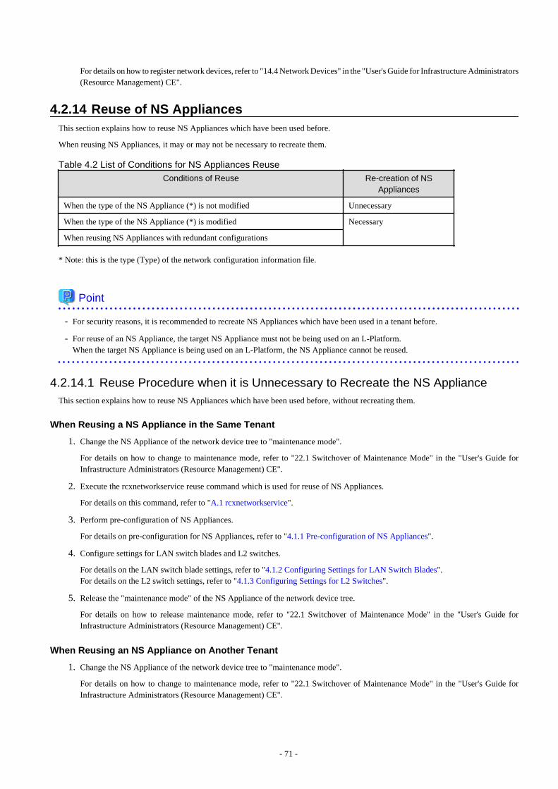
For details on how to register network devices, refer to "14.4 Network Devices" in the "User's Guide for Infrastructure Administrators(Resource Management) CE".
4.2.14 Reuse of NS AppliancesThis section explains how to reuse NS Appliances which have been used before.
When reusing NS Appliances, it may or may not be necessary to recreate them.
Table 4.2 List of Conditions for NS Appliances Reuse
Conditions of Reuse Re-creation of NSAppliances
When the type of the NS Appliance (*) is not modified Unnecessary
When the type of the NS Appliance (*) is modified Necessary
When reusing NS Appliances with redundant configurations
* Note: this is the type (Type) of the network configuration information file.
Point
- For security reasons, it is recommended to recreate NS Appliances which have been used in a tenant before.
- For reuse of an NS Appliance, the target NS Appliance must not be being used on an L-Platform.When the target NS Appliance is being used on an L-Platform, the NS Appliance cannot be reused.
4.2.14.1 Reuse Procedure when it is Unnecessary to Recreate the NS ApplianceThis section explains how to reuse NS Appliances which have been used before, without recreating them.
When Reusing a NS Appliance in the Same Tenant
1. Change the NS Appliance of the network device tree to "maintenance mode".
For details on how to change to maintenance mode, refer to "22.1 Switchover of Maintenance Mode" in the "User's Guide forInfrastructure Administrators (Resource Management) CE".
2. Execute the rcxnetworkservice reuse command which is used for reuse of NS Appliances.
For details on this command, refer to "A.1 rcxnetworkservice".
3. Perform pre-configuration of NS Appliances.
For details on pre-configuration for NS Appliances, refer to "4.1.1 Pre-configuration of NS Appliances".
4. Configure settings for LAN switch blades and L2 switches.
For details on the LAN switch blade settings, refer to "4.1.2 Configuring Settings for LAN Switch Blades".For details on the L2 switch settings, refer to "4.1.3 Configuring Settings for L2 Switches".
5. Release the "maintenance mode" of the NS Appliance of the network device tree.
For details on how to release maintenance mode, refer to "22.1 Switchover of Maintenance Mode" in the "User's Guide forInfrastructure Administrators (Resource Management) CE".
When Reusing an NS Appliance on Another Tenant
1. Change the NS Appliance of the network device tree to "maintenance mode".
For details on how to change to maintenance mode, refer to "22.1 Switchover of Maintenance Mode" in the "User's Guide forInfrastructure Administrators (Resource Management) CE".
- 71 -
2. Unregister the network device resource for the NS Appliance from the network pool.
For details, refer to "19.4 Unregistration" in the "User's Guide for Infrastructure Administrators (Resource Management) CE".
3. Execute the rcxnetworkservice reuse command which is used for reuse of NS Appliances.
For details on this command, refer to "A.1 rcxnetworkservice".
4. Perform pre-configuration of NS Appliances.
For details, refer to "4.1.1 Pre-configuration of NS Appliances".
5. Configure settings for LAN switch blades and L2 switches.
For details on the LAN switch blade settings, refer to "4.1.2 Configuring Settings for LAN Switch Blades".For details on the L2 switch settings, refer to "4.1.3 Configuring Settings for L2 Switches".
6. Register the network device for the NS Appliance in the network pool.
For details on how to register network devices to the network pool for the network devices, refer to "14.4 Network Devices" in the"User's Guide for Infrastructure Administrators (Resource Management) CE".
7. Release the "maintenance mode" of the NS Appliance of the network device tree.
For details on how to release maintenance mode, refer to "22.1 Switchover of Maintenance Mode" in the "User's Guide forInfrastructure Administrators (Resource Management) CE".
4.2.14.2 Reuse Procedure when it is Necessary to Recreate the NS ApplianceThis section explains how to recreate and reuse NS Appliances which have been used before.
When Using a Re-created NS Appliance on the Same Tenant
1. Change the NS Appliance of the network device tree to "maintenance mode".
For details on how to change to maintenance mode, refer to "22.1 Switchover of Maintenance Mode" in the "User's Guide forInfrastructure Administrators (Resource Management) CE".
2. Stop an NS Appliance.
For details on how to stop an NS Appliance, refer to "4.2.2 Stopping NS Appliances".
3. Delete an NS Appliance.
For details on how to delete an NS Appliance, refer to "4.2.11 Deleting (Deleting NS Appliances)".
4. Create an NS Appliance.
For details on how to create an NS Appliance, refer to "3.5 Creating NS Appliances".
5. Perform environment setup for the NS Appliance.
For details on environment setup for NS Appliances, refer to "3.6 Configuring NS Appliances".
6. Perform pre-configuration of NS Appliances.
For details on pre-configuration for NS Appliances, refer to "4.1.1 Pre-configuration of NS Appliances".
7. Configure settings for LAN switch blades and L2 switches.
For details on the LAN switch blade settings, refer to "4.1.2 Configuring Settings for LAN Switch Blades". For details on the L2switch settings, refer to "4.1.3 Configuring Settings for L2 Switches".
8. Release the "maintenance mode" of the NS Appliance of the network device tree.
For details on how to release maintenance mode, refer to "22.1 Switchover of Maintenance Mode" in the "User's Guide forInfrastructure Administrators (Resource Management) CE".
- 72 -

When Using a Re-created NS Appliance on Another Tenant
1. Change the NS Appliance of the network device tree to "maintenance mode".
For details on how to change to maintenance mode, refer to "22.1 Switchover of Maintenance Mode" in the "User's Guide forInfrastructure Administrators (Resource Management) CE".
2. Unregister the network device resource for the NS Appliance from the network pool.
For details on how to unregister network devices, refer to "19.4 Unregistration" in the "User's Guide for Infrastructure Administrators(Resource Management) CE".
3. Stop an NS Appliance.
For details on how to stop an NS Appliance, refer to "4.2.2 Stopping NS Appliances".
4. Delete an NS Appliance.
For details on how to delete an NS Appliance, refer to "4.2.11 Deleting (Deleting NS Appliances)".
5. Create an NS Appliance.
For details on how to create an NS Appliance, refer to "3.5 Creating NS Appliances".
6. Perform environment setup for the NS Appliance.
For details on environment setup for NS Appliances, refer to "3.6 Configuring NS Appliances".
7. Perform pre-configuration of NS Appliances.
For details on pre-configuration for NS Appliances, refer to "4.1.1 Pre-configuration of NS Appliances".
8. Release the "maintenance mode" of the NS Appliance of the network device tree.
For details on how to release maintenance mode, refer to "22.1 Switchover of Maintenance Mode" in the "User's Guide forInfrastructure Administrators (Resource Management) CE".
9. Configure settings for LAN switch blades and L2 switches.
For details on the LAN switch blade settings, refer to "4.1.2 Configuring Settings for LAN Switch Blades".For details on the L2 switch settings, refer to "4.1.3 Configuring Settings for L2 Switches".
10. Register the network device for the NS Appliance in the network pool.
For details on how to register network devices to the network pool for the network devices, refer to "14.4 Network Devices" in the"User's Guide for Infrastructure Administrators (Resource Management) CE".
4.2.15 Modifying FC Path ConfigurationsThis section explains the operation for modifying FC path configurations of physical L-Servers for NS Appliance.
This operation is only possible when physical L-Servers for NS Appliances are created using SAN storage.
1. Stop all the NS Appliances on the physical L-Server for NS Appliance.
For details on how to stop an NS Appliance, refer to "4.2.2 Stopping NS Appliances".
2. Stop the physical L-Server for NS Appliance.
For details on how to stop physical L-Servers, refer to "17.1.2 Stopping an L-Server" in the "User's Guide for InfrastructureAdministrators (Resource Management) CE".
3. Right-click the target L-Server in the orchestration tree.
4. In the displayed menu, select [Modify]-[Modify Specification].
5. In the displayed menu, select [Indicates the settings for when the server starts]-[FC path].
- When changing the FC path configuration from a single path configuration to a multi-path configuration
Uncheck the "single path-mode" checkbox.
- 73 -
- When changing the FC path configuration from a multi-path configuration to a single path configuration
Check the "single path-mode" checkbox.
6. Click the [OK] button.
7. Start a physical L-Server for NS Appliance.
For details on how to start physical L-Servers, refer to "17.1.1 Starting an L-Server" in the "User's Guide for InfrastructureAdministrators (Resource Management) CE".
8. Execute the rcxnetworkservice fcctl command.
Executing this command restarts the physical L-Server for NS Appliance.For details on this command, refer to "A.1 rcxnetworkservice".
9. Starts an NS Appliance.
For details on how to start an NS Appliance, refer to "4.2.1 Starting NS Appliances".
4.2.16 Increasing the Number of NS Appliances Allowed to OperateThis section explains the operation for changing the number of NS Appliances allowed to operate on a dedicated server for NS Appliancefrom 10 to 20.
This operation is not possible when physical L-Servers for NS Appliances have been created using SAN storage and FC multi-pathconfiguration has been set. Change the configuration to a FC single-path configuration before performing this operation.For details on modifying FC path configurations, refer to "4.2.15 Modifying FC Path Configurations".
1. Announce that maintenance operations will be performed.
Check the NS Appliances operating on the target dedicated server for NS Appliances, and if the target NS Appliance is being usedon the L-Platform, announce the start of maintenance operations to the tenant administrators and tenant users who use that L-Platform.For details, refer to "5.2.1.3 Announce the Start of Maintenance Operations".
2. Place all NS Appliances running on the target dedicated server for NS Appliances into maintenance mode.
For details on placing devices into maintenance mode, refer to "22.1 Switchover of Maintenance Mode" in the "User's Guide forInfrastructure Administrators (Resource Management) CE".
3. Stop all NS Appliances running on the target dedicated server for NS Appliances to perform maintenance on.
For details on how to stop an NS Appliance, refer to "4.2.2 Stopping NS Appliances".
4. Execute the rcxnetworkservice appext command to increase the number of NS Appliances that can be created.
Executing the rcxnetworkservice appext command restarts the physical L-Server for NS Appliance.For details on this command, refer to "A.1 rcxnetworkservice".
5. Release all of the NS Appliances running on the target dedicated server for NS Appliances from maintenance mode.
For details of how to release devices from maintenance mode, refer to "22.1 Switchover of Maintenance Mode" in the "User's Guidefor Infrastructure Administrators (Resource Management) CE".
6. Announce the end of maintenance.
Check the NS Appliances operating on the target dedicated server for NS Appliances, and if the target NS Appliance is being usedon the L-Platform, announce the end of maintenance operations to the tenant administrators and tenant users who use that L-Platform.For details, refer to "5.2.1.11 Announce the Completion of Maintenance Operations".
4.2.17 Modifying Admin LAN NetworksThis section explains modification of admin LAN networks.
Target resources of admin LAN networks for modification and the availability of modification are shown below.
- 74 -
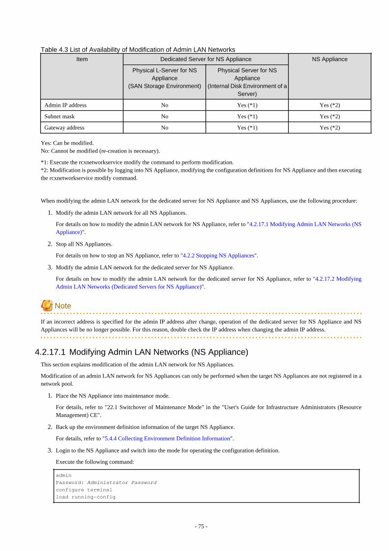
Table 4.3 List of Availability of Modification of Admin LAN NetworksItem Dedicated Server for NS Appliance NS Appliance
Physical L-Server for NSAppliance
(SAN Storage Environment)
Physical Server for NSAppliance
(Internal Disk Environment of aServer)
Admin IP address No Yes (*1) Yes (*2)
Subnet mask No Yes (*1) Yes (*2)
Gateway address No Yes (*1) Yes (*2)
Yes: Can be modified.No: Cannot be modified (re-creation is necessary).
*1: Execute the rcxnetworkservice modify the command to perform modification.*2: Modification is possible by logging into NS Appliance, modifying the configuration definitions for NS Appliance and then executingthe rcxnetworkservice modify command.
When modifying the admin LAN network for the dedicated server for NS Appliance and NS Appliances, use the following procedure:
1. Modify the admin LAN network for all NS Appliances.
For details on how to modify the admin LAN network for NS Appliance, refer to "4.2.17.1 Modifying Admin LAN Networks (NSAppliance)".
2. Stop all NS Appliances.
For details on how to stop an NS Appliance, refer to "4.2.2 Stopping NS Appliances".
3. Modify the admin LAN network for the dedicated server for NS Appliance.
For details on how to modify the admin LAN network for the dedicated server for NS Appliance, refer to "4.2.17.2 ModifyingAdmin LAN Networks (Dedicated Servers for NS Appliance)".
Note
If an incorrect address is specified for the admin IP address after change, operation of the dedicated server for NS Appliance and NSAppliances will be no longer possible. For this reason, double check the IP address when changing the admin IP address.
4.2.17.1 Modifying Admin LAN Networks (NS Appliance)This section explains modification of the admin LAN network for NS Appliances.
Modification of an admin LAN network for NS Appliances can only be performed when the target NS Appliances are not registered in anetwork pool.
1. Place the NS Appliance into maintenance mode.
For details, refer to "22.1 Switchover of Maintenance Mode" in the "User's Guide for Infrastructure Administrators (ResourceManagement) CE".
2. Back up the environment definition information of the target NS Appliance.
For details, refer to "5.4.4 Collecting Environment Definition Information".
3. Login to the NS Appliance and switch into the mode for operating the configuration definition.
Execute the following command:
admin
Password: Administrator Passwordconfigure terminal
load running-config
- 75 -
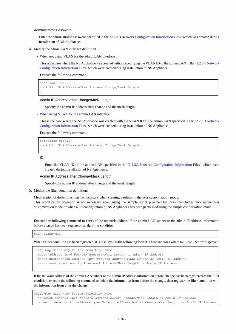
Administrator Password
Enter the administrator password specified in the "2.2.3.3 Network Configuration Information Files" which was created duringinstallation of NS Appliance.
4. Modify the admin LAN interface definition.
- When not using VLAN for the admin LAN interface
This is the case where the NS Appliance was created without specifying the VLAN ID of the admin LAN in the "2.2.3.3 NetworkConfiguration Information Files" which were created during installation of NS Appliance.
Execute the following command:
interface lan0.3
ip Admin IP Address after Address Change/Mask Length!
Admin IP Address after Change/Mask Length
Specify the admin IP address after change and the mask length.
- When using VLAN for the admin LAN interface
This is the case where the NS Appliance was created with the VLAN ID of the admin LAN specified in the "2.2.3.3 NetworkConfiguration Information Files" which were created during installation of NS Appliance.
Execute the following command:
interface vlanIDip Admin IP Address after Address Change/Mask Length!
ID
Enter the VLAN ID of the admin LAN specified in the "2.2.3.3 Network Configuration Information Files" which werecreated during installation of NS Appliance.
Admin IP Address after Change/Mask Length
Specify the admin IP address after change and the mask length.
5. Modify the filter condition definition.
Modification of definitions may be necessary when creating a ruleset in the user customization mode.This modification operation is not necessary when using the sample script provided by Resource Orchestrator in the usercustomization mode or when auto-configuration of NS Appliances has been performed using the simple configuration mode.
Execute the following command to check if the network address of the admin LAN subnet or the admin IP address informationbefore change has been registered as the filter condition.
show class-map
When a filter condition has been registered, it is displayed in the following format. There are cases where multiple lines are displayed.
class-map match-any Filter Condition Name match address ipv4 Network Address/Mask Length or Admin IP Address match destination-address ipv4 Network Address/Mask Length or Admin IP Address match source-address ipv4 Network Address/Mask Length or Admin IP Address!
If the network address of the admin LAN subnet or the admin IP address information before change has been registered as the filtercondition, execute the following command to delete the information from before the change, then register the filter condition withthe information from after the change.
class-map match-any Filter Condition Name no match address ipv4 Network Address before Change/Mask Length or Admin IP Address no match destination-address ipv4 Network Address before Change/Mask Length or Admin IP Address
- 76 -

no match source-address ipv4 Network Address before Change/Mask Length or Admin IP Address match address ipv4 Network Address after Change/Mask Length or Admin IP Address match destination-address ipv4 Network Address after Change/Mask Length or Admin IP Address match source--address ipv4 Network Address after Change/Mask Length or Admin IP Address!
Filter Condition Name
Specify the same character string as the filter condition name displayed when checking using show class-map.
Network Address before Change/Mask Length or Admin IP Address
Specify the network address and mask length of the admin LAN subnet or the admin IP address of NS appliance from beforethe change.
Network Address after Change/Mask Length or Admin IP Address
Specify the network address and mask length of the admin LAN subnet or the admin IP address of NS appliance from after thechange.
6. Modify the definition of the route information (routing).
Modify the definition of the route information when the network configuration is different before and after changing the admin IPaddress of the NS Appliance.
Execute the following command to check if the route information for communication with the admin server has been registered.
show ip route
When the route information has been registered, it is displayed in the following format. There are cases where multiple lines aredisplayed.
ip route Network Address/Mask Length Gateway Address
Check the displayed registration information to see if the same network address as that of admin LAN subnet has been registered.If the same network address is registered, execute the following command to delete the route information.
no ip route Network Address of the Admin LAN Subnet for the Admin Server/Mask Length Gateway Address
Network Address of the Admin LAN Subnet for the Admin Server/Mask Length
Specify the network address and mask length of the admin LAN subnet for the admin server.
Gateway Address
Specify a gateway address that can be used to access the admin LAN subnet of the admin server.
If the network after changing the admin IP address of the NS Appliance is different from the network of the admin LAN subnet ofthe admin server, execute the following command to register the route information:
ip route Network Address of the Admin LAN Subnet for the Admin Server/Mask Length Gateway Address
Network Address of the Admin LAN Subnet for the Admin Server/Mask Length
Specify the network address and mask length of the admin LAN subnet for the admin server.
Gateway Address
Specify a gateway address that can be used to access the admin LAN subnet of the admin server.
7. Save the configuration definition on the NS Appliance.
Execute the following command:
save startup-config
After executing the command, when the following message is displayed, enter "y".
- 77 -

Do you overwrite "startup-config" by the current configuration? (y|[n]):y
8. Stop an NS Appliance.
Execute the following command:
poweroff
After executing the command, when the following message is displayed, enter "y".
A power off of the system disconnects all communications. Are you sure?(y|[n]):y
9. Execute the rcxnetworkservice list command to check that the NS Appliance has stopped.
For details on this command, refer to "A.1 rcxnetworkservice".Before the NS Appliance management information is updated by execution of the rcxnetworkservice modify command, the IPaddress displayed with the rcxnetworkservice list command is the same address as the IP address before changing.
10. Execute the rcxnetworkservice modify command to update the management information of the NS Appliance.
For details on this command, refer to "A.1 rcxnetworkservice".
11. Modify the network device information.
Reflect the admin IP address of the NS Appliance after change on the network device information.For the change operation, use the network configuration information created during installation of the NS Appliance.Modifying the admin IP address for multiple network devices at the same time is not possible. Perform the modification for onedevice at a time.For details on how to modify network device information, refer to "7.6 Changing Network Device Settings" in the "User's Guidefor Infrastructure Administrators (Resource Management) CE".
12. Starts the target NS Appliance.
For details on how to start an NS Appliance, refer to "4.2.1 Starting NS Appliances".
13. Release the NS Appliance from maintenance mode.
For details of how to release devices from maintenance mode, refer to "22.1 Switchover of Maintenance Mode" in the "User's Guidefor Infrastructure Administrators (Resource Management) CE".
4.2.17.2 Modifying Admin LAN Networks (Dedicated Servers for NS Appliance)This section explains modification of the admin LAN network of physical servers (environments for built-in disks of the server) for NSAppliances.
1. Announce that maintenance operations will be performed.
Check the NS Appliances operating on the target dedicated physical server for NS Appliances, and if the target NS Appliance isbeing used on the L-Platform, announce the start of maintenance operations to the tenant administrators and tenant users who usethat L-Platform.For details, refer to "3.2 Editing the Home Messages" in the "User's Guide for Infrastructure Administrators CE".
2. Place all of the NS Appliances running on the target physical server for NS Appliances into maintenance mode.
For details, refer to "22.1 Switchover of Maintenance Mode" in the "User's Guide for Infrastructure Administrators (ResourceManagement) CE".
3. Back up the environment definition information for all of the NS Appliances that are running on the target physical server for NSAppliances.
For details, refer to "5.4.4 Collecting Environment Definition Information".
4. Stop all of the NS Appliances running on the target physical server for NS Appliances.
For details on how to stop an NS Appliance, refer to "4.2.2 Stopping NS Appliances".
- 78 -
5. Execute the rcxnetworkservice modify command to change the admin IP address of the physical server for NS Appliances.
Executing the rcxnetworkservice modify command restarts the physical server for NS Appliance.For details on this command, refer to "A.1 rcxnetworkservice".
6. In the server resource tree of the ROR console, right-click the target physical server for NS Appliances, and select [Modify]-[Registration Settings] from the displayed popup menu.
The [Modify Server Settings] dialog is displayed.
7. Change the value of [Admin LAN (IP address)].
Specify the admin IP address from after the change specified at step 5.
8. Click the [OK] button.
The admin IP address of the managed server is changed.
9. Release all of the NS Appliances running on the target physical server for NS Appliances from maintenance mode.
For details on how to release maintenance mode, refer to "22.1 Switchover of Maintenance Mode" in the "User's Guide forInfrastructure Administrators (Resource Management) CE".
10. Announce the end of maintenance.
Check the NS Appliances operating on the target dedicated physical server for NS Appliances, and if the target NS Appliance isbeing used on the L-Platform, announce the end of maintenance operations to the tenant administrators and tenant users who usethat L-Platform.For details, refer to "3.2 Editing the Home Messages" in the "User's Guide for Infrastructure Administrators CE".
Information
- When changing to an IP address different from the admin LAN subnet IP address of the admin server, it is necessary to register theadmin LAN subnet that the IP address after change belongs to, in advance.For details, refer to "5.11 Registering Admin LAN Subnets" in the "User's Guide for Infrastructure Administrators (ResourceManagement) CE".
- Changing of the IP address of the management host (ManagementHost) is not necessary even when it has been specified and registeredas a resource in the network configuration information file which was created during installation of the NS Appliance.It is reflected when the admin IP address of the physical server for NS Appliance is changed.
When managing the information specified when registering the NS Appliance as a resource using the network configurationinformation file, change the IP address of the management host (ManagementHost) in the network configuration information file.
4.3 Disaster Recovery OperationsPhysical L-Servers for NS Appliances are targets of Disaster Recovery.
However, note the following points:
- When using NS Appliances as network devices, prepare physical L-Servers for NS Appliances based on the units in which switchoverwill be performed.
- Specify the name of the physical server used to create the physical L-Server of NS Appliance. Use the same physical server namesbetween sites.
- As was done for the other network devices, create an NS Appliance at the backup site and register it as a network device beforehand.
- "backup of configurations" and "copying of configurations", both of which are performed for firewall units, are not necessary.
For details, refer to "DR Option Instruction".
- 79 -
Chapter 5 MaintenanceThis chapter explains how to operate NS Appliances.
5.1 Preparations for MaintenanceThis section explains the preparations and information necessary for maintenance.
- Maintenance work requires a FTP server. Set up the FTP server environment beforehand.
- During maintenance operations, there are cases where the operator's device needs to connect to NS Appliances.Default ports used for connection in these cases differ depending on the connection protocol as follow:
- When connecting from a Telnet client device
23/tcp
- When connecting from a SSHv2 client device
22/tcp
5.2 Application of Updates for NS OptionThis section explains how to apply updates for NS Option.
There are two methods to provide updates for NS Option:
- Patches for NS Appliance
Update image files for NS Appliance.Use this type of update to apply updates to NS Appliances.
- NS Option Media Pack
Cloning images for NS Option.This type of update contains update images for NS Appliance and the program which controls NS Appliances on dedicated L-Servers.Use them for the following cases:
- When creating a dedicated server for NS Appliance on which the latest NS Appliance and the control program operate
- When updating the NS Appliance and the control program on a dedicated server for the NS Appliance which has been alreadyinstalled
Note
- An L-Platform with NS Appliances being updated cannot be used until the maintenance of NS Option is completed.
- Applying updates deletes the log data for the NS Appliance. If there is any necessary log data, such as session logs, collect the logdata before applying updates. For details on how to collect log data, refer to "5.4.1 Collecting Log Data".
- When applying updates using the "NS Option Media Pack", it is necessary to re-create the dedicated server for NS Appliance.
- Apply updates using the "NS Option Media Pack" in the following cases:
- If no NS Appliance has been created on a dedicated server for NS Appliances
- When an L-Platform using a created NS Appliance has not been created
- If updates are applied using "patches for NS Appliance", any new NS Appliances created after that will be as follows:
- If created on the same dedicated server as an NS Appliance with the patches applied
NS Appliances with the "patches for NS Appliance" applied will be created.
- 80 -

- If created on a dedicated server which does not have any NS Appliances with the patches applied
NS Appliances without the "patches for NS Appliance" applied will be created.To create an NS Appliance with the "patches for NS Appliance" applied, perform either of the following operations:
- Apply the "patches for NS Appliance" to an existing NS Appliance which is up and running.
- Use the "NS Option Media Pack" and re-create the dedicated server for the NS Appliance.
5.2.1 Application of Patches for NS ApplianceThis section explains how to apply updates to NS Appliances.
5.2.1.1 Patch Application ProcedureThe procedure to apply patches is as follows:
Unless otherwise stated, the following operations should be performed by the infrastructure administrator.
1. Store Patch Files
2. Announce the Start of Maintenance Operations
3. Set the Maintenance Mode
4. Back up the Environment Definition Information
5. Stop NS Appliances
6. Apply Patches
7. Start NS Appliances
8. Restore the Environment Definition Information
9. Release the Maintenance Mode
10. Announce the Completion of Maintenance Operations
Point
When using NS Appliances with redundant configurations, use the following procedure to apply patches:
a. Apply patches to NS Appliances in stand-by mode.Perform step 3 - step 9 of the patch application procedure.
b. Perform switchover of redundant NS Appliances.
c. After switchover, apply patches to the NS Appliance placed in stand-by mode.Perform step 3 - step 9 of the patch application procedure.
d. After performing the above operations, confirm the following:
- The NS Appliance that had patches applied is in the correct status.The statuses of NS Appliances can be confirmed using the rcxnetworkservice list command.
- That each device of the redundant pair is configured as a primary device and a secondary device, respectively.
For details on how to check the operating statuses of redundant NS Appliances, refer to "5.5.1 Confirming Redundancy ConfigurationStatus".For details on how to switchover the operating status of redundant NS Appliances, refer to "5.5.2 Switchover of Redundancy Status".For details on the rcxnetworkservice command, refer to "A.1 rcxnetworkservice".
- 81 -

5.2.1.2 Store Patch FilesStore the downloaded patch files for NS Appliance (image files for NS Appliance) in the location of your choosing on the system wherethe ROR manager is installed.
However, do not store the image files for NS Appliance using the installation path of the ROR manager.
5.2.1.3 Announce the Start of Maintenance OperationsAnnounce the start of maintenance operations to the tenant administrators and tenant users who are using the L-Platform on which targetNS Appliances are deployed.
Operation Target
None
Operation
Edit the information displayed on the Home window of the ROR console to announce the start of maintenance operations to tenantadministrators and tenant users.For details, refer to "3.2 Editing the Home Messages" in the "User's Guide for Infrastructure Administrators CE".
Point
Wait for the tenant administrators and tenant users to complete necessary actions in response to the announcement of the start ofmaintenance before proceeding to the next step.
5.2.1.4 Set Maintenance ModePlace the NS Appliance to maintenance on into "maintenance mode".
Operation Target
The network device corresponding to the NS Appliance to maintain
Operation
Place the network device corresponding to the NS Appliance to perform maintenance on into "maintenance mode" from the RORconsole or the command line.For the procedure to place devices into maintenance mode, refer to "22.1 Switchover of Maintenance Mode" in the "User's Guide forInfrastructure Administrators (Resource Management) CE".
5.2.1.5 Back up the Environment Definition InformationBack up the environment definition information of the NS Appliance to apply the patches to.
Operation Target
The NS Appliance to maintain
Operation
Log in to the "admin-LAN IP address" of the NS Appliance to perform maintenance on from a Telnet or SSHv2 client and then backup the environment definition information.For details, refer to "5.4.4 Collecting Environment Definition Information".
5.2.1.6 Stop NS AppliancesStop the NS Appliance to maintain.
Operation Target
The NS Appliance to maintain
- 82 -
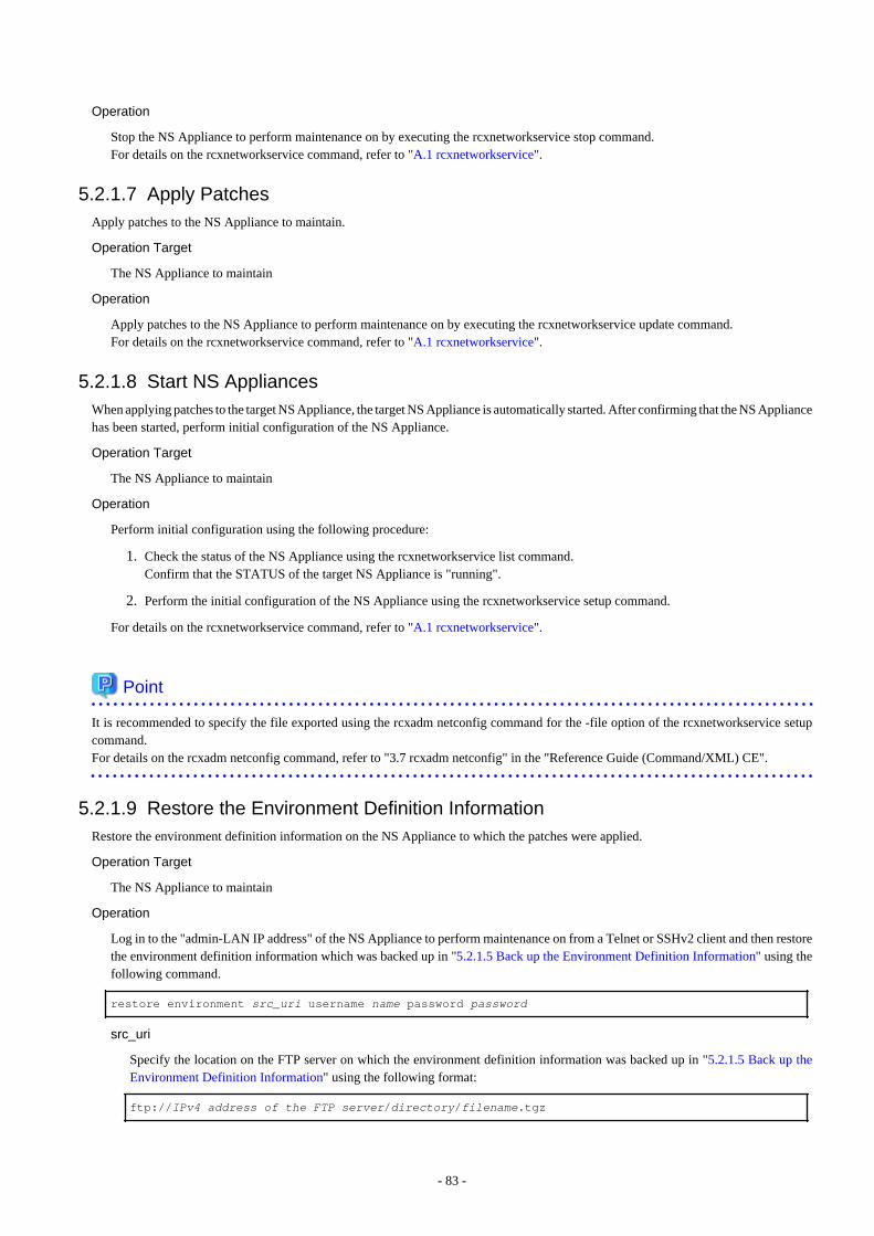
Operation
Stop the NS Appliance to perform maintenance on by executing the rcxnetworkservice stop command.For details on the rcxnetworkservice command, refer to "A.1 rcxnetworkservice".
5.2.1.7 Apply PatchesApply patches to the NS Appliance to maintain.
Operation Target
The NS Appliance to maintain
Operation
Apply patches to the NS Appliance to perform maintenance on by executing the rcxnetworkservice update command.For details on the rcxnetworkservice command, refer to "A.1 rcxnetworkservice".
5.2.1.8 Start NS AppliancesWhen applying patches to the target NS Appliance, the target NS Appliance is automatically started. After confirming that the NS Appliancehas been started, perform initial configuration of the NS Appliance.
Operation Target
The NS Appliance to maintain
Operation
Perform initial configuration using the following procedure:
1. Check the status of the NS Appliance using the rcxnetworkservice list command.Confirm that the STATUS of the target NS Appliance is "running".
2. Perform the initial configuration of the NS Appliance using the rcxnetworkservice setup command.
For details on the rcxnetworkservice command, refer to "A.1 rcxnetworkservice".
Point
It is recommended to specify the file exported using the rcxadm netconfig command for the -file option of the rcxnetworkservice setupcommand.For details on the rcxadm netconfig command, refer to "3.7 rcxadm netconfig" in the "Reference Guide (Command/XML) CE".
5.2.1.9 Restore the Environment Definition InformationRestore the environment definition information on the NS Appliance to which the patches were applied.
Operation Target
The NS Appliance to maintain
Operation
Log in to the "admin-LAN IP address" of the NS Appliance to perform maintenance on from a Telnet or SSHv2 client and then restorethe environment definition information which was backed up in "5.2.1.5 Back up the Environment Definition Information" using thefollowing command.
restore environment src_uri username name password password
src_uri
Specify the location on the FTP server on which the environment definition information was backed up in "5.2.1.5 Back up theEnvironment Definition Information" using the following format:
ftp://IPv4 address of the FTP server/directory/filename.tgz
- 83 -
name
Specify the login ID for the FTP server using a character string containing between 1 and 64 characters.
password
Specify the password for the login ID for the FTP server using a character string containing between 1 and 64 characters.
5.2.1.10 Release Maintenance ModeRelease "maintenance mode" on the NS Appliance to which the patches were applied.
Operation Target
The network device corresponding to the NS Appliance to maintain
Operation
Release "maintenance mode" of the network device corresponding to the NS Appliance using the ROR console or the command line.For details on how to release maintenance mode, refer to "22.1 Switchover of Maintenance Mode" in the "User's Guide for InfrastructureAdministrators (Resource Management) CE".
5.2.1.11 Announce the Completion of Maintenance OperationsAnnounce the completion of maintenance operations to the tenant administrators and tenant users who are using the L-Platform on whichtarget NS Appliances are deployed.
Operation Target
None
Operation
Edit the information displayed on the Home window of the ROR console to announce the completion of maintenance operations totenant administrators and tenant users.
For details, refer to "3.2 Editing the Home Messages" in the "User's Guide for Infrastructure Administrators CE".
Point
The maintenance process is regarded as complete when the tenant administrators and tenant users complete any necessary actions inresponse to the announcement of the end of maintenance operations.
5.2.2 Applying the NS Option Media PackThis section explains how to apply the updates for NS Appliance and the program which controls NS Appliances on dedicated servers forNS Appliances.
When applying updates using the NS Option Media Pack, it is necessary to re-create the dedicated server for NS Appliances.
5.2.2.1 Patch Application ProcedureThe procedure to apply patches is as follows:
Unless otherwise stated, the following operations should be performed by the infrastructure administrator.
1. Announce the Start of Maintenance Operations
2. Set the Maintenance Mode
3. Back up the Environment Definition Information
4. Stop NS Appliances
5. Delete Dedicated Servers for NS Appliances
6. Create Dedicated Servers for NS Appliances
- 84 -

7. Create NS Appliances
8. Restore the Environment Definition Information
9. Release the Maintenance Mode
10. Announce the Completion of Maintenance Operations
Point
When using NS Appliances with redundant configurations, use the following procedure to apply patches:
a. Switch all of the NS Appliances operating on the dedicated server for NS Appliances on which patches are to be applied, into stand-by mode.
1. Check the status of redundancy configurations of NS Appliances.
2. If the target NS Appliances are in primary mode, switch them into stand-by mode.
b. Apply patches to the dedicated server for NS Appliances operated in step a.Perform step 2 - step 9 of the patch application procedure.Before releasing maintenance mode, confirm the following:
- The NS Appliance that had patches applied is in the correct status.The statuses of NS Appliances can be confirmed using the rcxnetworkservice list command.
- That the redundancy configuration status is in stand-by mode.
c. Switch all of the NS Appliances operating on the dedicated server for NS Appliances on which patches were applied, into primarymode.
d. Apply patches to the rest of the dedicated servers for NS Appliances that are used to configure redundancy.Use the same procedure as step b.
e. After performing the above operations, confirm the following:
- That all NS Appliances with patches applied are in the correct status.The statuses of NS Appliances can be confirmed using the rcxnetworkservice list command.
- That each device of the redundant pair is configured as a primary device and a secondary device, respectively.
For details on how to check the operating statuses of redundant NS Appliances, refer to "5.5.1 Confirming Redundancy ConfigurationStatus".For details on how to switchover the operating status of redundant NS Appliances, refer to "5.5.2 Switchover of Redundancy Status".For details on the rcxnetworkservice command, refer to "A.1 rcxnetworkservice".
5.2.2.2 Announce the Start of Maintenance OperationsAnnounce the start of maintenance operations to the tenant administrators and tenant users who are using the L-Platform on which targetNS Appliances are deployed.
For details, refer to "5.2.1.3 Announce the Start of Maintenance Operations".
5.2.2.3 Set Maintenance Mode on NS AppliancesSet "maintenance mode" on all of the NS Appliances on the dedicated servers for NS Appliances to perform maintenance on.
For details, refer to "5.2.1.4 Set Maintenance Mode".
5.2.2.4 Back up the Environment Definition InformationBack up the environment definition information for all of the NS Appliances that are running on the dedicated server for NS Appliancesto perform maintenance on.
For details, refer to "5.2.1.5 Back up the Environment Definition Information".
- 85 -
5.2.2.5 Stop NS AppliancesStop all of the NS Appliances running on the dedicated server for NS Appliances to perform maintenance on.
For details, refer to "5.2.1.6 Stop NS Appliances".
5.2.2.6 Delete Dedicated Servers for NS AppliancesDelete the dedicated server for NS Appliances to perform maintenance on.
Operation Target
The dedicated server for NS Appliances and all of the NS Appliances running on it
Operation
Delete the dedicated server for NS Appliances using the following procedure:
1. Delete NS Appliances.For details, refer to "4.2.11 Deleting (Deleting NS Appliances)".
2. Delete the dedicated server for NS Appliances.
Confirm that there are no NS Appliances on the target dedicated server for NS Appliances using the rcxnetworkservice listcommand, and then delete the dedicated server for NS Appliances.
- When the dedicated server for NS Appliances is a physical L-Server
For details, refer to "17.4 Deleting" of the "User's Guide for Infrastructure Administrators (Resource Management) CE".
- When the dedicated server for NS Appliances is a physical server
For details, refer to "9.2 Deleting Managed Servers" of the "User's Guide for Infrastructure Administrators (ResourceManagement) CE".
For details on the rcxnetworkservice command, refer to "A.1 rcxnetworkservice".
5.2.2.7 Recreate Dedicated Servers for NS AppliancesRecreate the dedicated server for NS Appliances.For details, refer to "3.3 Creating Dedicated Servers for NS Appliance".
When the dedicated server for NS Appliances is a physical server, it is necessary to register the managed server as a resource.For details on how to register resources, refer to "Chapter 5 Registering Resources" in the "User's Guide for Infrastructure Administrators(Resource Management) CE".
5.2.2.8 Create NS AppliancesCreate the same number of NS Appliances as those before patches were applied, on the recreated dedicated server for NS Appliances.
For details, refer to "3.5 Creating NS Appliances".
5.2.2.9 Restore the Environment Definition InformationRestore the environment definition information for all of the NS Appliances that were running on the dedicated server for NS Appliancesto perform maintenance on.
For details, refer to "5.2.1.9 Restore the Environment Definition Information".
5.2.2.10 Release the Maintenance Mode of NS AppliancesRelease "maintenance mode" of all of the NS Appliances on the recreated dedicated server for NS Appliances.
For details, refer to "5.2.1.10 Release Maintenance Mode".
- 86 -
5.2.2.11 Announce the Completion of Maintenance OperationsAnnounce the completion of maintenance operations to the tenant administrators and tenant users who are using the L-Platform on whichtarget NS Appliances are deployed.
For details, refer to "5.2.1.11 Announce the Completion of Maintenance Operations".
5.3 Maintenance When Failure Occurs on Dedicated Servers for NSAppliances
This section explains the recovery procedure for when a dedicated server dedicated for NS Appliances used in a single configuration fails.
When using an internal disk, it is necessary to back up the network device file for NS Appliances using the network device file managementfunctions before performing the recovery operation.
For details on the network device file management function, refer to "10.2 Backup and Restoration of Network Devices" in the "OperationGuide CE".
1. Change the status of the NS Appliance to maintenance mode
On the ROR console, change the status of all NS Appliances on the failed physical server to maintenance mode.
2. Maintain hardware
Replace failed servers.
- When using the BX series
Refer to "9.2 Blade Server Maintenance" in the "Operation Guide CE".
- When using the RX series
Refer to "9.3 Maintenance for Servers Other Than Blade Servers" in the "Operation Guide CE".
3. Recover NS Appliances
It is not necessary to perform recovery operations of NS Appliances when using SAN storage.
It is necessary to create physical servers for NS Appliances again when using an internal disk.
- Create a physical server for NS Appliance
Refer to "3.3.3 Creating Physical Servers (When Using the Internal Disk of a Server)".
- Create an NS Appliance on a physical server using the rcxnetworkservice create command
Refer to "3.5 Creating NS Appliances".
- Configure the environment for the created NS Appliance using the rcxnetworkservice setup command
Refer to "3.6 Configuring NS Appliances".
- Restore NS Appliance configuration files
Refer to "10.2.3 Restoration of Network Devices" in the "Operation Guide CE".
4. Release the maintenance mode of NS Appliances
On the ROR console, release the statuses of all NS Appliances on the failed physical server from maintenance mode.
For the procedure to change or release maintenance mode, refer to "22.1 Switchover of Maintenance Mode" in the "User's Guidefor Infrastructure Administrators (Resource Management) CE".
Information
When using a redundancy configuration, it is necessary to synchronize the definitions of the NS Appliances that compose the redundancyconfiguration pair before releasing the NS Appliance to perform maintenance on from maintenance mode, using the following procedure:
1. Connect to the NS Appliances which compose the redundancy pair using a Telnet or SSHv2 client.
- 87 -
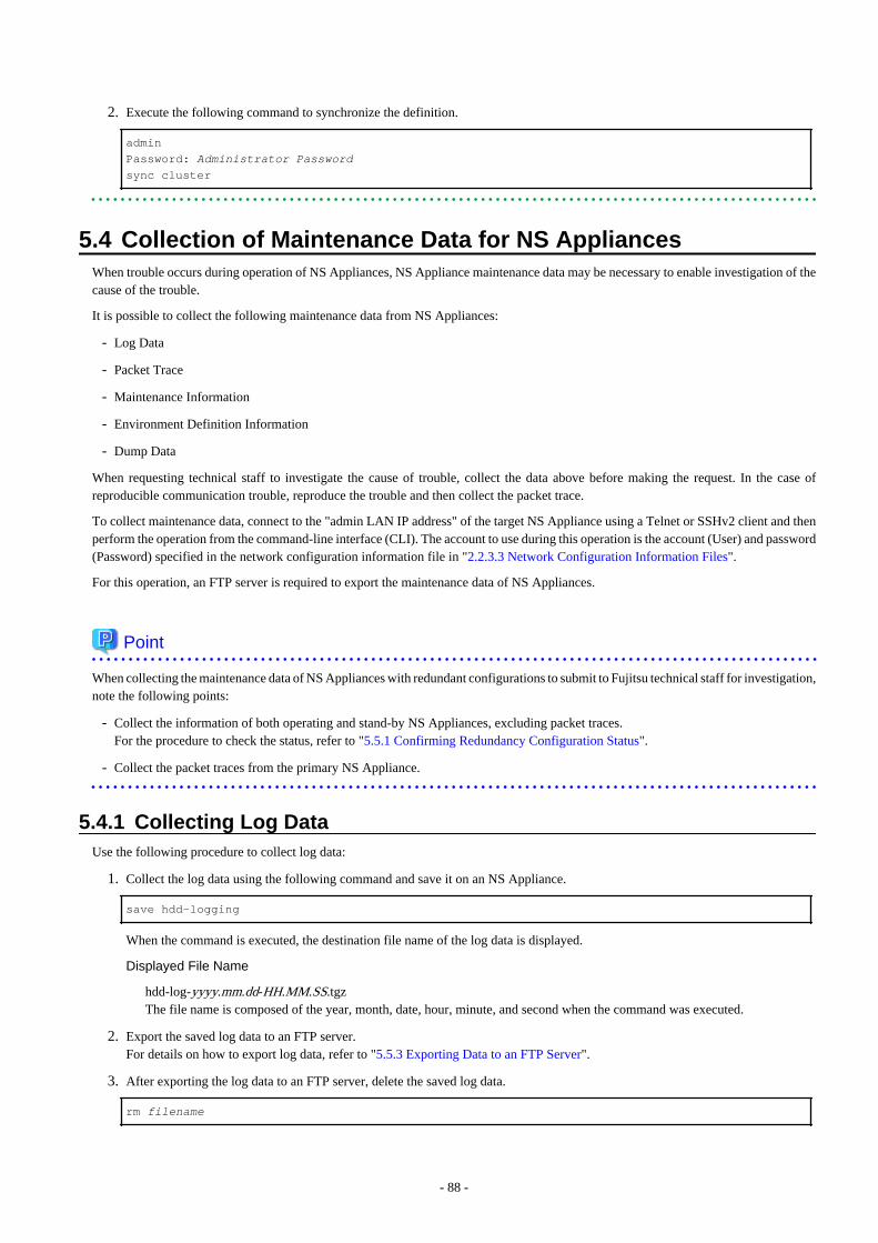
2. Execute the following command to synchronize the definition.
admin
Password: Administrator Passwordsync cluster
5.4 Collection of Maintenance Data for NS AppliancesWhen trouble occurs during operation of NS Appliances, NS Appliance maintenance data may be necessary to enable investigation of thecause of the trouble.
It is possible to collect the following maintenance data from NS Appliances:
- Log Data
- Packet Trace
- Maintenance Information
- Environment Definition Information
- Dump Data
When requesting technical staff to investigate the cause of trouble, collect the data above before making the request. In the case ofreproducible communication trouble, reproduce the trouble and then collect the packet trace.
To collect maintenance data, connect to the "admin LAN IP address" of the target NS Appliance using a Telnet or SSHv2 client and thenperform the operation from the command-line interface (CLI). The account to use during this operation is the account (User) and password(Password) specified in the network configuration information file in "2.2.3.3 Network Configuration Information Files".
For this operation, an FTP server is required to export the maintenance data of NS Appliances.
Point
When collecting the maintenance data of NS Appliances with redundant configurations to submit to Fujitsu technical staff for investigation,note the following points:
- Collect the information of both operating and stand-by NS Appliances, excluding packet traces.For the procedure to check the status, refer to "5.5.1 Confirming Redundancy Configuration Status".
- Collect the packet traces from the primary NS Appliance.
5.4.1 Collecting Log DataUse the following procedure to collect log data:
1. Collect the log data using the following command and save it on an NS Appliance.
save hdd-logging
When the command is executed, the destination file name of the log data is displayed.
Displayed File Name
hdd-log-yyyy.mm.dd-HH.MM.SS.tgzThe file name is composed of the year, month, date, hour, minute, and second when the command was executed.
2. Export the saved log data to an FTP server.For details on how to export log data, refer to "5.5.3 Exporting Data to an FTP Server".
3. After exporting the log data to an FTP server, delete the saved log data.
rm filename
- 88 -
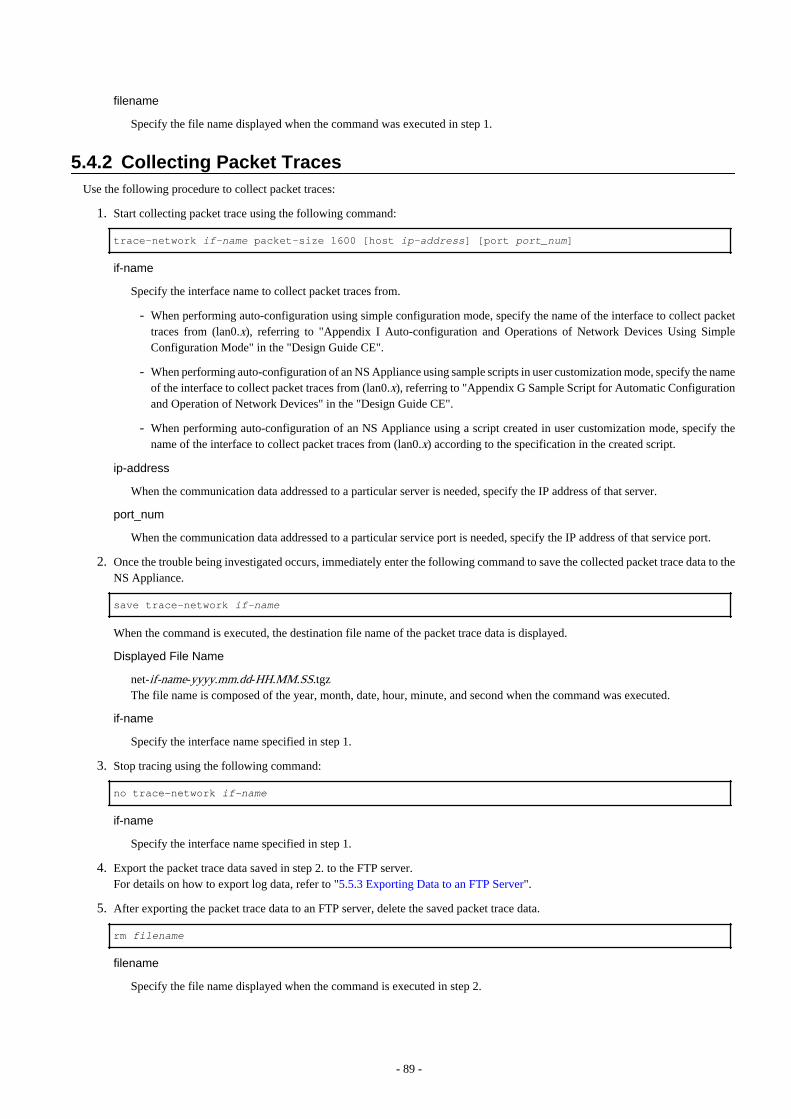
filename
Specify the file name displayed when the command was executed in step 1.
5.4.2 Collecting Packet TracesUse the following procedure to collect packet traces:
1. Start collecting packet trace using the following command:
trace-network if-name packet-size 1600 [host ip-address] [port port_num]
if-name
Specify the interface name to collect packet traces from.
- When performing auto-configuration using simple configuration mode, specify the name of the interface to collect packettraces from (lan0.x), referring to "Appendix I Auto-configuration and Operations of Network Devices Using SimpleConfiguration Mode" in the "Design Guide CE".
- When performing auto-configuration of an NS Appliance using sample scripts in user customization mode, specify the nameof the interface to collect packet traces from (lan0.x), referring to "Appendix G Sample Script for Automatic Configurationand Operation of Network Devices" in the "Design Guide CE".
- When performing auto-configuration of an NS Appliance using a script created in user customization mode, specify thename of the interface to collect packet traces from (lan0.x) according to the specification in the created script.
ip-address
When the communication data addressed to a particular server is needed, specify the IP address of that server.
port_num
When the communication data addressed to a particular service port is needed, specify the IP address of that service port.
2. Once the trouble being investigated occurs, immediately enter the following command to save the collected packet trace data to theNS Appliance.
save trace-network if-name
When the command is executed, the destination file name of the packet trace data is displayed.
Displayed File Name
net-if-name-yyyy.mm.dd-HH.MM.SS.tgzThe file name is composed of the year, month, date, hour, minute, and second when the command was executed.
if-name
Specify the interface name specified in step 1.
3. Stop tracing using the following command:
no trace-network if-name
if-name
Specify the interface name specified in step 1.
4. Export the packet trace data saved in step 2. to the FTP server.For details on how to export log data, refer to "5.5.3 Exporting Data to an FTP Server".
5. After exporting the packet trace data to an FTP server, delete the saved packet trace data.
rm filename
filename
Specify the file name displayed when the command is executed in step 2.
- 89 -

5.4.3 Collecting Maintenance InformationUse the following procedure to collect maintenance information:
1. Collect debugging information for the NS Appliance using the following commands:
show tech-support
save slb persistence
Execute the "save slb persistence" command only when using server load balancing functions.
When the command is executed, the destination file name of the debugging information is displayed.
File Name Displayed When Executing the show tech-support Command
tech-hostname-yyyy.mm.dd-HH.MM.SS.tgzThe file name is composed of the year, month, date, hour, minute, and second when the command was executed.
File Name Displayed When Executing the save slb persistence Command
slb-persist-info-yyyy.mm.dd-HH.MM.SS.tgzThe file name is composed of the year, month, date, hour, minute, and second when the command was executed.
2. Export the saved debugging information to an FTP server.To transfer multiple files to an FTP server, execute the command for each file.For details on how to export the debugging information, refer to "5.5.3 Exporting Data to an FTP Server".
3. After exporting the debugging information to an FTP server, delete the saved debugging information.To delete multiple files, execute the command for each file.
rm filename
filename
Specify the file name displayed when the command is executed in step 1.
5.4.4 Collecting Environment Definition InformationUse the following procedure to collect the environment definition information:
1. Back up the environment definition information for the NS Appliance using the following command:
backup environment dst_uri username name password password
dst_uri
Specify the location on the FTP server to which the information will be backed up.
ftp://IPv4 address of the FTP server/directory/filename.tgz
For "filename.tgz", specify a character string containing between 5 and 128 characters, including the extension ".tgz".
name
Specify the login ID for the FTP server using a character string containing between 1 and 64 characters.
password
Specify the password for the login ID for the FTP server using a character string containing between 1 and 64 characters.
5.4.5 Collecting Dump DataUse the following procedure to collect dump data:
1. Check whether dump data exists using the following command:
ls
If dump data exists, one of the following files exists:
- 90 -
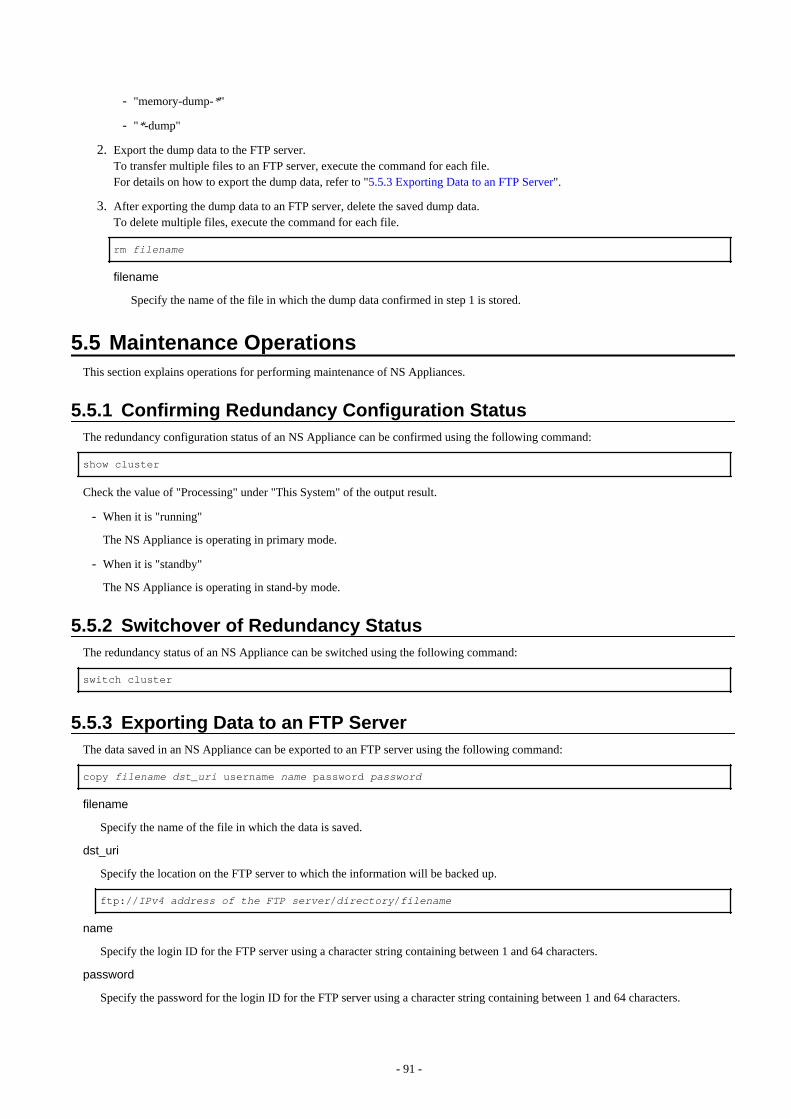
- "memory-dump-*"
- "*-dump"
2. Export the dump data to the FTP server.To transfer multiple files to an FTP server, execute the command for each file.For details on how to export the dump data, refer to "5.5.3 Exporting Data to an FTP Server".
3. After exporting the dump data to an FTP server, delete the saved dump data.To delete multiple files, execute the command for each file.
rm filename
filename
Specify the name of the file in which the dump data confirmed in step 1 is stored.
5.5 Maintenance OperationsThis section explains operations for performing maintenance of NS Appliances.
5.5.1 Confirming Redundancy Configuration StatusThe redundancy configuration status of an NS Appliance can be confirmed using the following command:
show cluster
Check the value of "Processing" under "This System" of the output result.
- When it is "running"
The NS Appliance is operating in primary mode.
- When it is "standby"
The NS Appliance is operating in stand-by mode.
5.5.2 Switchover of Redundancy StatusThe redundancy status of an NS Appliance can be switched using the following command:
switch cluster
5.5.3 Exporting Data to an FTP ServerThe data saved in an NS Appliance can be exported to an FTP server using the following command:
copy filename dst_uri username name password password
filename
Specify the name of the file in which the data is saved.
dst_uri
Specify the location on the FTP server to which the information will be backed up.
ftp://IPv4 address of the FTP server/directory/filename
name
Specify the login ID for the FTP server using a character string containing between 1 and 64 characters.
password
Specify the password for the login ID for the FTP server using a character string containing between 1 and 64 characters.
- 91 -
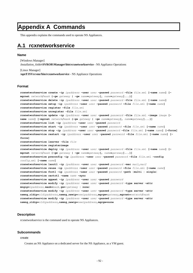
Appendix A CommandsThis appendix explains the commands used to operate NS Appliances.
A.1 rcxnetworkservice
Name
[Windows Manager]Installation_folder\SVROR\Manager\bin\rcxnetworkservice - NS Appliance Operations
[Linux Manager]/opt/FJSVrcvmr/bin/rcxnetworkservice - NS Appliance Operations
Format
rcxnetworkservice create -ip ipaddress -user user -passwd password -file file.xml [-name name] [-
mgrnet network/mask {-gw gateway | -gw name=gateway[, name=gateway]...}]
rcxnetworkservice delete -ip ipaddress -user user -passwd password -file file.xml [-name name]
rcxnetworkservice setup -ip ipaddress -user user -passwd password -file file.xml [-name name]
rcxnetworkservice register -file file.xml
rcxnetworkservice unregister -file file.xml
rcxnetworkservice update -ip ipaddress -user user -passwd password -file file.xml -image image [-
name name] [-mgrnet network/mask {-gw gateway | -gw name=gateway[, name=gateway]...}]
rcxnetworkservice list -ip ipaddress -user user -passwd password
rcxnetworkservice start -ip ipaddress -user user -passwd password -file file.xml [-name name]
rcxnetworkservice stop -ip ipaddress -user user -passwd password -file file.xml [-name name] [-force]
rcxnetworkservice restart -ip ipaddress -user user -passwd password -file file.xml [-name name] [-
force]
rcxnetworkservice lserver -file filercxnetworkservice registerimage
rcxnetworkservice deploy -ip ipaddress -user user -passwd password -file file.xml [-name name] [-
mgrnet network/mask {-gw gateway | -gw name=gateway[, name=gateway]...}]
rcxnetworkservice preconfig -ip ipaddress -user user -passwd password -file file.xml -config
config.xml [-name name]
rcxnetworkservice lanctl -ip ipaddress -user user -passwd password -mac mac1,mac2
rcxnetworkservice reuse -ip ipaddress -user user -passwd password -file file.xml [-name name]
rcxnetworkservice fcctl -ip ipaddress -user user -passwd password -path {multi | single}
rcxnetworkservice certctl -name name -sync
rcxnetworkservice appext -ip ipaddress -user user -passwd password
rcxnetworkservice modify -ip ipaddress -user user -passwd password -type server -attr
mngip=ipaddress,mask=mask,gw={gateway | none}
rcxnetworkservice modify -ip ipaddress -user user -passwd password -type server -attr
nsmng_oldip=oldipaddress,nsmng_newip=newipaddress,mgrgw=gateway,mgrnet=network/mask
rcxnetworkservice modify -ip ipaddress -user user -passwd password -type server -attr
nsmng_oldip=oldipaddress,nsmng_newip=newipaddress,mgrgw=none
Description
rcxnetworkservice is the command used to operate NS Appliances.
Subcommands
create
Creates an NS Appliance on a dedicated server for the NS Appliance, as a VM guest.
- 92 -
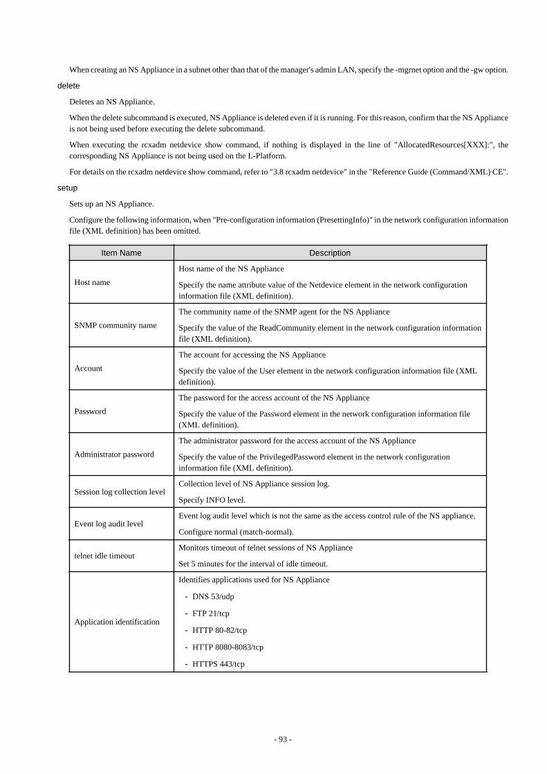
When creating an NS Appliance in a subnet other than that of the manager's admin LAN, specify the -mgrnet option and the -gw option.
delete
Deletes an NS Appliance.
When the delete subcommand is executed, NS Appliance is deleted even if it is running. For this reason, confirm that the NS Applianceis not being used before executing the delete subcommand.
When executing the rcxadm netdevice show command, if nothing is displayed in the line of "AllocatedResources[XXX]:", thecorresponding NS Appliance is not being used on the L-Platform.
For details on the rcxadm netdevice show command, refer to "3.8 rcxadm netdevice" in the "Reference Guide (Command/XML) CE".
setup
Sets up an NS Appliance.
Configure the following information, when "Pre-configuration information (PresettingInfo)" in the network configuration informationfile (XML definition) has been omitted.
Item Name Description
Host name
Host name of the NS Appliance
Specify the name attribute value of the Netdevice element in the network configurationinformation file (XML definition).
SNMP community name
The community name of the SNMP agent for the NS Appliance
Specify the value of the ReadCommunity element in the network configuration informationfile (XML definition).
Account
The account for accessing the NS Appliance
Specify the value of the User element in the network configuration information file (XMLdefinition).
Password
The password for the access account of the NS Appliance
Specify the value of the Password element in the network configuration information file(XML definition).
Administrator password
The administrator password for the access account of the NS Appliance
Specify the value of the PrivilegedPassword element in the network configurationinformation file (XML definition).
Session log collection levelCollection level of NS Appliance session log.
Specify INFO level.
Event log audit levelEvent log audit level which is not the same as the access control rule of the NS appliance.
Configure normal (match-normal).
telnet idle timeoutMonitors timeout of telnet sessions of NS Appliance
Set 5 minutes for the interval of idle timeout.
Application identification
Identifies applications used for NS Appliance
- DNS 53/udp
- FTP 21/tcp
- HTTP 80-82/tcp
- HTTP 8080-8083/tcp
- HTTPS 443/tcp
- 93 -
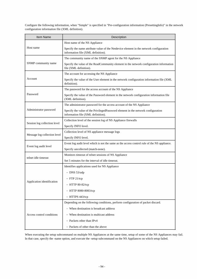
Configure the following information, when "Simple" is specified in "Pre-configuration information (PresettingInfo)" in the networkconfiguration information file (XML definition).
Item Name Description
Host name
Host name of the NS Appliance
Specify the name attribute value of the Netdevice element in the network configurationinformation file (XML definition).
SNMP community name
The community name of the SNMP agent for the NS Appliance
Specify the value of the ReadCommunity element in the network configuration informationfile (XML definition).
Account
The account for accessing the NS Appliance
Specify the value of the User element in the network configuration information file (XMLdefinition).
Password
The password for the access account of the NS Appliance
Specify the value of the Password element in the network configuration information file(XML definition).
Administrator password
The administrator password for the access account of the NS Appliance
Specify the value of the PrivilegedPassword element in the network configurationinformation file (XML definition).
Session log collection levelCollection level of the session log of NS Appliance firewalls
Specify INFO level.
Message log collection levelCollection level of NS appliance message logs
Specify INFO level.
Event log audit levelEvent log audit level which is not the same as the access control rule of the NS appliance.
Specify uncollected (match-none).
telnet idle timeoutMonitors timeout of telnet sessions of NS Appliance
Set 5 minutes for the interval of idle timeout.
Application identification
Identifies applications used for NS Appliance
- DNS 53/udp
- FTP 21/tcp
- HTTP 80-82/tcp
- HTTP 8080-8083/tcp
- HTTPS 443/tcp
Access control conditions
Depending on the following conditions, perform configuration of packet discard.
- When destination is broadcast address
- When destination is multicast address
- Packets other than IPv4
- Packets of other than the above
When executing the setup subcommand on multiple NS Appliances at the same time, setup of some of the NS Appliances may fail.In that case, specify the -name option, and execute the -setup subcommand on the NS Appliances on which setup failed.
- 94 -
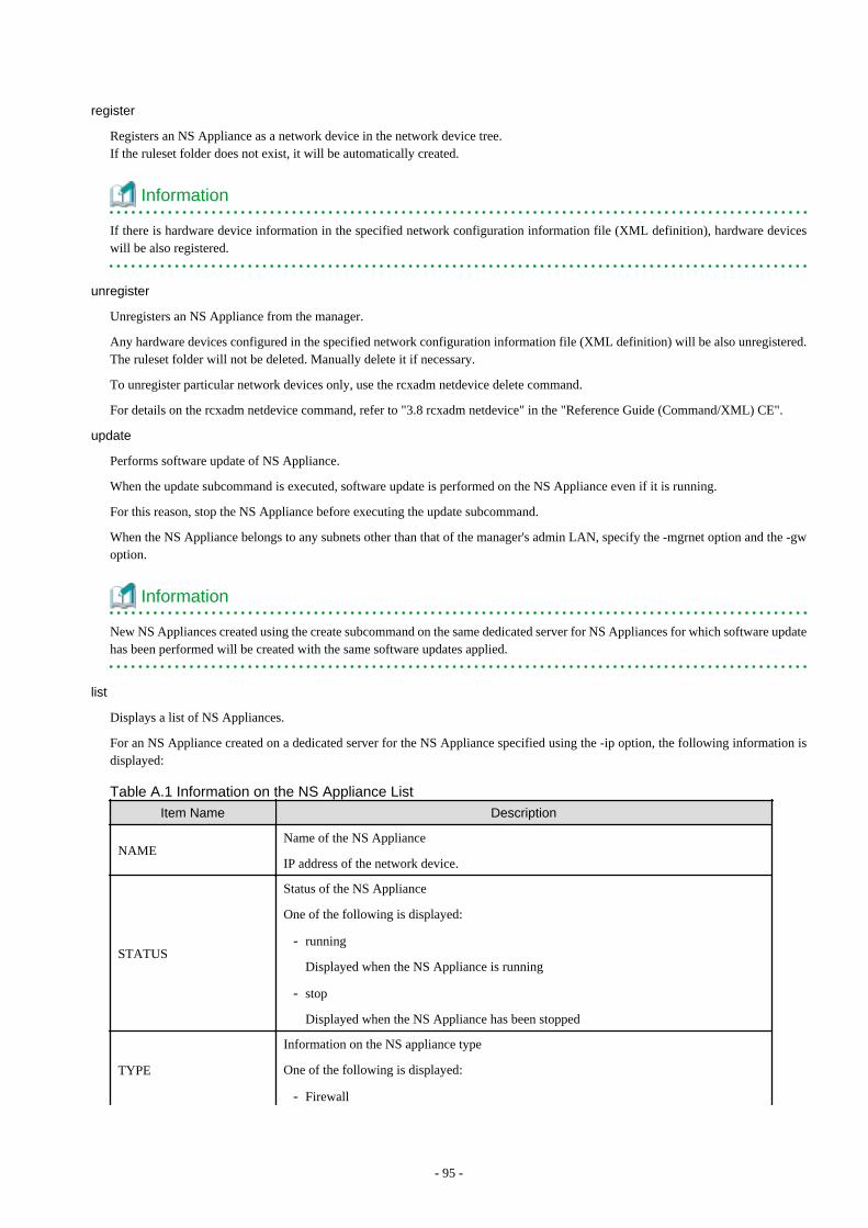
register
Registers an NS Appliance as a network device in the network device tree.If the ruleset folder does not exist, it will be automatically created.
Information
If there is hardware device information in the specified network configuration information file (XML definition), hardware deviceswill be also registered.
unregister
Unregisters an NS Appliance from the manager.
Any hardware devices configured in the specified network configuration information file (XML definition) will be also unregistered.The ruleset folder will not be deleted. Manually delete it if necessary.
To unregister particular network devices only, use the rcxadm netdevice delete command.
For details on the rcxadm netdevice command, refer to "3.8 rcxadm netdevice" in the "Reference Guide (Command/XML) CE".
update
Performs software update of NS Appliance.
When the update subcommand is executed, software update is performed on the NS Appliance even if it is running.
For this reason, stop the NS Appliance before executing the update subcommand.
When the NS Appliance belongs to any subnets other than that of the manager's admin LAN, specify the -mgrnet option and the -gwoption.
Information
New NS Appliances created using the create subcommand on the same dedicated server for NS Appliances for which software updatehas been performed will be created with the same software updates applied.
list
Displays a list of NS Appliances.
For an NS Appliance created on a dedicated server for the NS Appliance specified using the -ip option, the following information isdisplayed:
Table A.1 Information on the NS Appliance List
Item Name Description
NAMEName of the NS Appliance
IP address of the network device.
STATUS
Status of the NS Appliance
One of the following is displayed:
- running
Displayed when the NS Appliance is running
- stop
Displayed when the NS Appliance has been stopped
TYPE
Information on the NS appliance type
One of the following is displayed:
- Firewall
- 95 -

Item Name Description
When using a firewall
- Firewall/SLB
When using an integrated network device
start
Starts an NS Appliance.
stop
Stops an NS Appliance.
When executing the stop subcommand for the NS Appliance which has not been set up using the rcxnetworkservice setup command,specify the -force option.
If the stop subcommand is executed without the -force option specified, an error will occur.
restart
Restarts an NS Appliance.
The restart subcommand cannot be used on an NS Appliance which has not been set up using the rcxnetworkservice setup command.Stop the NS Appliance using the -force option of the stop subcommand, and then start it using the start subcommand.
lserver
Creates a physical L-Server for NS Appliance.
L-Servers can be created using commands when the following conditions are satisfied. If these conditions are not satisfied, create themusing the GUI.
- When creating a dedicated server for NS Appliances using SAN storage
- When using an admin LAN in which NIC1 and NIC2 are in a redundant configuration
Information
The XML file specified when creating the dedicated server for NS Appliances is saved using the following filename in the same folderas the specified file:
NS_XML_filename.xml
Example
Specified file: /root/ns_server
File to be saved: /root/NS_ns_server.xml
registerimage
Registers the cloning image for NS option that is stored in the image file storage folder with ROR CE manager.
deploy
Deploys (creates or configures) NS appliances
When creating an NS Appliance in a subnet other than that of the manager's admin LAN, specify the -mgrnet option and the -gw option.
preconfig
Performs pre-configuration of NS appliances.
Specify the following information:
- 96 -

Item Name Description
Interface definition on the publicLAN
Interface on the NS appliance public LAN
Configure the following items based on the information in the NS appliance pre-configuration file (XML definition).
- VLAN
- IP address
- IP routing
- Access control
- RIP routing
Definition of the route information(routing).
NS appliance route information
Configure the values of the gateway element in the NS appliance pre-configurationfile (XML definition).
For details on the pre-configuration settings, refer to "C.2 Pre-configuration".
lanctl
Configures the network settings of the physical server for NS appliance.
Only specify it when using the internal disk of the physical server for NS appliance.
After executing this command, the physical server for an NS appliance restarts.
reuse
Initializes and reconfigures an NS Appliance.
The following settings are initialized:
- Configuration definitions
The following information is deleted:
- Logs
- Certificates
- SLB error response files
For details on the information reconfigured, refer to the setup subcommand.
fcctl
Sets the FC path configuration of a physical L-Server for NS Appliances.
Specify only when using the SAN storage on which the physical L-Server for NS Appliances operates.
After executing this command, the physical L-Server for an NS Appliance restarts.
certctl
Performs management of certificate information for NS Appliances.
appext
Changes the maximum number of NS Appliances that operate on the dedicated server for NS Option from 10 to 20.
After executing this command, the dedicated server for NS Appliance is restarted.
modify
Changes the settings of the dedicated server for NS Option.
- 97 -

Options
-ip ipaddress
In ipaddress, specify an IP address to access the dedicated server for NS Appliances used for NS Appliance creation.
-user user
In user, specify a user ID to use to access the dedicated server for NS Appliances used for NS Appliance creation.
-passwd password
In password, specify the password for the user ID to use to access the dedicated server for NS Appliances used for NS Appliancecreation.
-file file.xml
In file.xml, specify the network configuration information file (XML definition).
When using a network configuration information file (XML definition) in which batch creation of multiple network devices is defined,the operation will be performed on all defined NS Appliances.
Up to 10 NS Appliances (or 20 when expanded) can be created on a single dedicated server for NS Appliances.
Up to 10 (or 20 when expanded) different pieces of information can be specified for NS Appliances in the network configurationinformation file (XML definition) for NS Appliance operations.
When creating multiple dedicated servers for NS Appliances, create the same number of network configuration information files (XMLdefinitions) as the number of dedicated servers.
-config config.xml
In config.xml, specify the pre-configuration file (XML definition) of the NS appliance.
It is necessary to define the information corresponding to the NS appliance defined in the network configuration information file (XMLdefinition) specified using the -file option.
For details on the NS appliance pre-configuration file (XML definition), refer to "2.2.3.4 NS Appliance Pre-configuration File".
-name name
In name, specify the device name of the target NS Appliance.
The operation will be only performed on NS Appliances with device names specified in the network configuration information file(XML definition).
-mgrnet network/mask
In network/mask, specify the network address and mask value of the admin LAN of the manager.
In network, specify the address in the IPv4 address format.
In mask, specify a number between 1 and 32.
Example
When the admin LAN network address is 192.168.1.0 with a 24-bit mask
-mgrnet 192.168.1.0/24
-gw gateway
In gateway, specify the IP address of the gateway used by the NS Appliance to access the admin LAN of the manager, in the IPv4address format.
When multiple NS Appliances are defined in the network configuration information file (XML definition) specified using the -fileoption, the gateway for all NS Appliances to be created will have the IP address specified in gateway. To configure different gatewaysfor individual NS Appliances, specify the -gw option using the name=gateway format.
- 98 -
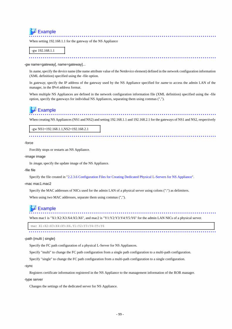
Example
When setting 192.168.1.1 for the gateway of the NS Appliance
-gw 192.168.1.1
-gw name=gateway[, name=gateway]...
In name, specify the device name (the name attribute value of the Netdevice element) defined in the network configuration information(XML definition) specified using the -file option.
In gateway, specify the IP address of the gateway used by the NS Appliance specified for name to access the admin LAN of themanager, in the IPv4 address format.
When multiple NS Appliances are defined in the network configuration information file (XML definition) specified using the -fileoption, specify the gateways for individual NS Appliances, separating them using commas (",").
Example
When creating NS Appliances (NS1 and NS2) and setting 192.168.1.1 and 192.168.2.1 for the gateways of NS1 and NS2, respectively
-gw NS1=192.168.1.1,NS2=192.168.2.1
-force
Forcibly stops or restarts an NS Appliance.
-image image
In image, specify the update image of the NS Appliance.
-file file
Specify the file created in "2.2.3.6 Configuration Files for Creating Dedicated Physical L-Servers for NS Appliance".
-mac mac1.mac2
Specify the MAC addresses of NICs used for the admin LAN of a physical server using colons (":") as delimiters.
When using two MAC addresses, separate them using commas (",").
Example
When mac1 is "X1:X2:X3:X4:X5:X6", and mac2 is "Y1:Y2:Y3:Y4:Y5:Y6" for the admin LAN NICs of a physical server.
-mac X1:X2:X3:X4:X5:X6,Y1:Y2:Y3:Y4:Y5:Y6
-path {multi | single}
Specify the FC path configuration of a physical L-Server for NS Appliances.
Specify "multi" to change the FC path configuration from a single path configuration to a multi-path configuration.
Specify "single" to change the FC path configuration from a multi-path configuration to a single configuration.
-sync
Registers certificate information registered in the NS Appliance to the management information of the ROR manager.
-type server
Changes the settings of the dedicated server for NS Appliance.
- 99 -
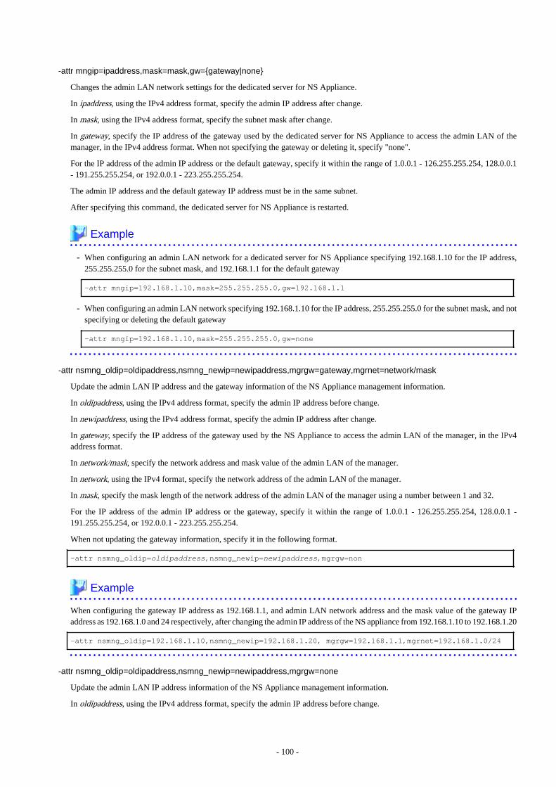
-attr mngip=ipaddress,mask=mask,gw={gateway|none}
Changes the admin LAN network settings for the dedicated server for NS Appliance.
In ipaddress, using the IPv4 address format, specify the admin IP address after change.
In mask, using the IPv4 address format, specify the subnet mask after change.
In gateway, specify the IP address of the gateway used by the dedicated server for NS Appliance to access the admin LAN of themanager, in the IPv4 address format. When not specifying the gateway or deleting it, specify "none".
For the IP address of the admin IP address or the default gateway, specify it within the range of 1.0.0.1 - 126.255.255.254, 128.0.0.1- 191.255.255.254, or 192.0.0.1 - 223.255.255.254.
The admin IP address and the default gateway IP address must be in the same subnet.
After specifying this command, the dedicated server for NS Appliance is restarted.
Example
- When configuring an admin LAN network for a dedicated server for NS Appliance specifying 192.168.1.10 for the IP address,255.255.255.0 for the subnet mask, and 192.168.1.1 for the default gateway
-attr mngip=192.168.1.10,mask=255.255.255.0,gw=192.168.1.1
- When configuring an admin LAN network specifying 192.168.1.10 for the IP address, 255.255.255.0 for the subnet mask, and notspecifying or deleting the default gateway
-attr mngip=192.168.1.10,mask=255.255.255.0,gw=none
-attr nsmng_oldip=oldipaddress,nsmng_newip=newipaddress,mgrgw=gateway,mgrnet=network/mask
Update the admin LAN IP address and the gateway information of the NS Appliance management information.
In oldipaddress, using the IPv4 address format, specify the admin IP address before change.
In newipaddress, using the IPv4 address format, specify the admin IP address after change.
In gateway, specify the IP address of the gateway used by the NS Appliance to access the admin LAN of the manager, in the IPv4address format.
In network/mask, specify the network address and mask value of the admin LAN of the manager.
In network, using the IPv4 format, specify the network address of the admin LAN of the manager.
In mask, specify the mask length of the network address of the admin LAN of the manager using a number between 1 and 32.
For the IP address of the admin IP address or the gateway, specify it within the range of 1.0.0.1 - 126.255.255.254, 128.0.0.1 -191.255.255.254, or 192.0.0.1 - 223.255.255.254.
When not updating the gateway information, specify it in the following format.
-attr nsmng_oldip=oldipaddress,nsmng_newip=newipaddress,mgrgw=non
Example
When configuring the gateway IP address as 192.168.1.1, and admin LAN network address and the mask value of the gateway IPaddress as 192.168.1.0 and 24 respectively, after changing the admin IP address of the NS appliance from 192.168.1.10 to 192.168.1.20
-attr nsmng_oldip=192.168.1.10,nsmng_newip=192.168.1.20, mgrgw=192.168.1.1,mgrnet=192.168.1.0/24
-attr nsmng_oldip=oldipaddress,nsmng_newip=newipaddress,mgrgw=none
Update the admin LAN IP address information of the NS Appliance management information.
In oldipaddress, using the IPv4 address format, specify the admin IP address before change.
- 100 -
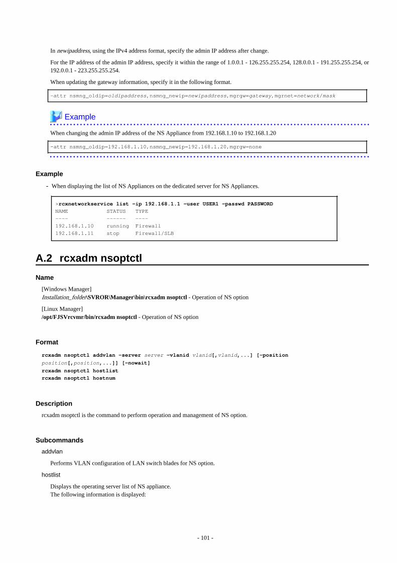
In newipaddress, using the IPv4 address format, specify the admin IP address after change.
For the IP address of the admin IP address, specify it within the range of 1.0.0.1 - 126.255.255.254, 128.0.0.1 - 191.255.255.254, or192.0.0.1 - 223.255.255.254.
When updating the gateway information, specify it in the following format.
-attr nsmng_oldip=oldipaddress,nsmng_newip=newipaddress,mgrgw=gateway,mgrnet=network/mask
Example
When changing the admin IP address of the NS Appliance from 192.168.1.10 to 192.168.1.20
-attr nsmng_oldip=192.168.1.10,nsmng_newip=192.168.1.20,mgrgw=none
Example
- When displaying the list of NS Appliances on the dedicated server for NS Appliances.
>rcxnetworkservice list -ip 192.168.1.1 -user USER1 -passwd PASSWORD
NAME STATUS TYPE
---- ------ ----
192.168.1.10 running Firewall
192.168.1.11 stop Firewall/SLB
A.2 rcxadm nsoptctl
Name
[Windows Manager]Installation_folder\SVROR\Manager\bin\rcxadm nsoptctl - Operation of NS option
[Linux Manager]/opt/FJSVrcvmr/bin/rcxadm nsoptctl - Operation of NS option
Format
rcxadm nsoptctl addvlan -server server -vlanid vlanid[,vlanid,...] [-position
position[,position,...]] [-nowait]
rcxadm nsoptctl hostlist
rcxadm nsoptctl hostnum
Description
rcxadm nsoptctl is the command to perform operation and management of NS option.
Subcommands
addvlan
Performs VLAN configuration of LAN switch blades for NS option.
hostlist
Displays the operating server list of NS appliance.The following information is displayed:
- 101 -
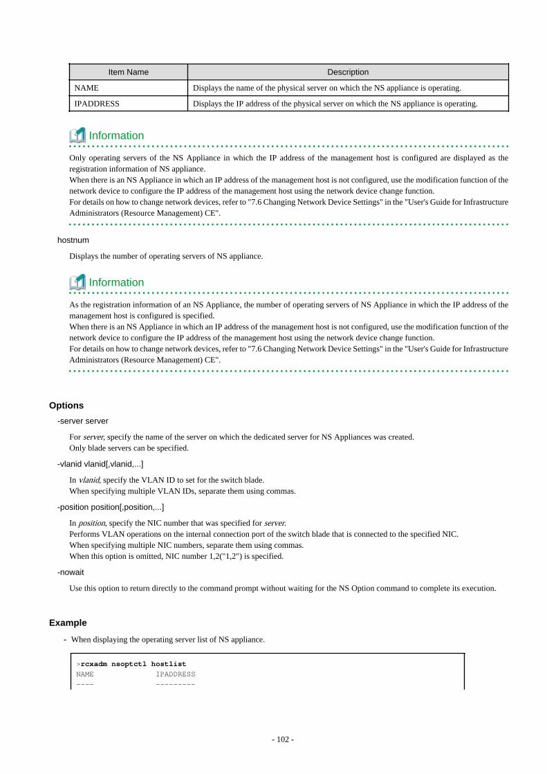
Item Name Description
NAME Displays the name of the physical server on which the NS appliance is operating.
IPADDRESS Displays the IP address of the physical server on which the NS appliance is operating.
Information
Only operating servers of the NS Appliance in which the IP address of the management host is configured are displayed as theregistration information of NS appliance.When there is an NS Appliance in which an IP address of the management host is not configured, use the modification function of thenetwork device to configure the IP address of the management host using the network device change function.For details on how to change network devices, refer to "7.6 Changing Network Device Settings" in the "User's Guide for InfrastructureAdministrators (Resource Management) CE".
hostnum
Displays the number of operating servers of NS appliance.
Information
As the registration information of an NS Appliance, the number of operating servers of NS Appliance in which the IP address of themanagement host is configured is specified.When there is an NS Appliance in which an IP address of the management host is not configured, use the modification function of thenetwork device to configure the IP address of the management host using the network device change function.For details on how to change network devices, refer to "7.6 Changing Network Device Settings" in the "User's Guide for InfrastructureAdministrators (Resource Management) CE".
Options
-server server
For server, specify the name of the server on which the dedicated server for NS Appliances was created.Only blade servers can be specified.
-vlanid vlanid[,vlanid,...]
In vlanid, specify the VLAN ID to set for the switch blade.When specifying multiple VLAN IDs, separate them using commas.
-position position[,position,...]
In position, specify the NIC number that was specified for server.Performs VLAN operations on the internal connection port of the switch blade that is connected to the specified NIC.When specifying multiple NIC numbers, separate them using commas.When this option is omitted, NIC number 1,2("1,2") is specified.
-nowait
Use this option to return directly to the command prompt without waiting for the NS Option command to complete its execution.
Example
- When displaying the operating server list of NS appliance.
>rcxadm nsoptctl hostlist
NAME IPADDRESS
---- ---------
- 102 -

NS-SERVER01 192.168.1.10
NS-SERVER02 192.168.1.11
- When displaying the number of operating servers of NS appliance.
>rcxadm nsoptctl hostnum
2
- 103 -

Appendix B Port ListThis appendix explains the ports used by NS Option.
The following figure shows the connection configuration of NS Option components.
Figure B.1 Connection Configuration
The following tables show the port numbers used by NS Option. Communications should be allowed for each of these ports in order forNS Option to operate properly.
Table B.1 Admin Server
FunctionOverview
Source Destination
ProtocolServer Service Port
Modificatio
nServer Service Port
Modificatio
n
Monitoringand controllingresources
Adminserver
-Variablevalue
Notpossible
A dedicatedserver for NSAppliance
ssh 22Notpossible
tcp
-Variablevalue
Notpossible
rpcbind 111Notpossible
tcp
-Variablevalue
Notpossible
NFSVariablevalue
Notpossible
tcp
-Variablevalue
Notpossible
- (*1) 3172Notpossible
tcp
-Variablevalue
Notpossible
teradataordbms
8002Notpossible
tcp
-Variablevalue
Notpossible
nfagent
rcvat (*2)23458
Notpossible
tcp
-Variablevalue
Notpossible
rpcbind 111Notpossible
udp
-Variablevalue
Notpossible
ntp 123Notpossible
udp
-Variablevalue
Notpossible
snmp 161Notpossible
udp
-Variablevalue
Notpossible
avahi 5353Notpossible
udp
- 104 -
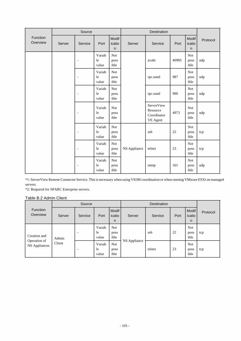
FunctionOverview
Source Destination
ProtocolServer Service Port
Modificatio
nServer Service Port
Modificatio
n
-Variablevalue
Notpossible
avahi 40985Notpossible
udp
-Variablevalue
Notpossible
rpc.statd 987Notpossible
udp
-Variablevalue
Notpossible
rpc.statd 990Notpossible
udp
-Variablevalue
Notpossible
ServerViewResourceCoordinatorVE Agent
4973Notpossible
udp
-Variablevalue
Notpossible
NS Appliance
ssh 22Notpossible
tcp
-Variablevalue
Notpossible
telnet 23Notpossible
tcp
-Variablevalue
Notpossible
snmp 161Notpossible
udp
*1: ServerView Remote Connector Service. This is necessary when using VIOM coordination or when running VMware ESXi on managedservers.*2: Required for SPARC Enterprise servers.
Table B.2 Admin Client
FunctionOverview
Source Destination
ProtocolServer Service Port
Modificatio
nServer Service Port
Modificatio
n
Creation andOperation ofNS Appliances
AdminClient
-Variablevalue
Notpossible
NS Appliance
ssh 22Notpossible
tcp
-Variablevalue
Notpossible
telnet 23Notpossible
tcp
- 105 -
Appendix C Pre-configuration Method for NS AppliancesThis appendix explains how to perform pre-configuration of NS appliances when using automatic configuration.
- Pre-configuration
Configure the definitions required for auto-configuration of NS Appliances.
- Server Certificate and CA Certificate Operations
Register or update certificates necessary for use of the SSL accelerator of the server load balancing function.
For these operations, the following information must be obtained from tenant users beforehand.
- When using simple configuration mode
- Server certificate
- The registration number of the server certificate
- CA certificate (*1)
- When using user customization mode
- Server certificate
- The registration number of the server certificate
- CA certificate (*1)
*1: Necessary when using a server certificate issued by a CA for which the CA certificate has not been registered on the client side.
- Error Page Response File Operations
- When using simple configuration mode
Register or update the error page response file.
- When using user customization mode
Register or update the error page response file when using an HTTP error message response as an optional function of serverfailure monitoring of the server load balancer function.
C.1 Connection MethodWhen connecting with NS appliances, use Telnet (23/tcp) or SSHv2 (22/tcp) clients, and connect with the "admin LAN IP address" of theNS appliance to operate.
The account to use at this time is the user ID and password created in the network configuration information file in "2.2.3.3 NetworkConfiguration Information Files".
C.2 Pre-configurationThis section explains how to perform pre-configuration of NS appliances.
C.2.1 Pre-configuration to Use Simple Configuration ModeExplains the pre-configuration necessary to use simple configuration mode.
For details on the logical network configuration which can be configured using simple configuration mode, refer to "Appendix I Auto-configuration and Operations of Network Devices Using Simple Configuration Mode" in the "Design Guide CE".
Procedure for Configuration Creating the NS Appliance Pre-configuration File
Use the NS Appliance pre-configuration file created in preparations to perform configuration using the rcxnetworkservice preconfigcommand.
- 106 -
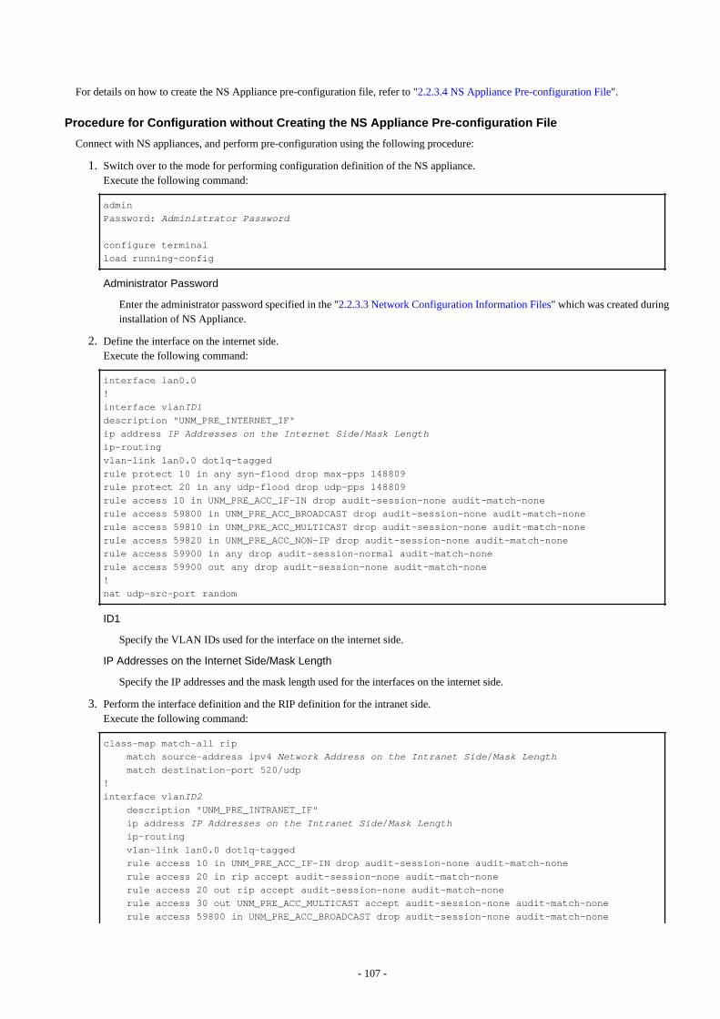
For details on how to create the NS Appliance pre-configuration file, refer to "2.2.3.4 NS Appliance Pre-configuration File".
Procedure for Configuration without Creating the NS Appliance Pre-configuration File
Connect with NS appliances, and perform pre-configuration using the following procedure:
1. Switch over to the mode for performing configuration definition of the NS appliance.Execute the following command:
admin
Password: Administrator Password
configure terminal
load running-config
Administrator Password
Enter the administrator password specified in the "2.2.3.3 Network Configuration Information Files" which was created duringinstallation of NS Appliance.
2. Define the interface on the internet side.Execute the following command:
interface lan0.0
!
interface vlanID1description "UNM_PRE_INTERNET_IF"
ip address IP Addresses on the Internet Side/Mask Lengthip-routing
vlan-link lan0.0 dot1q-tagged
rule protect 10 in any syn-flood drop max-pps 148809
rule protect 20 in any udp-flood drop udp-pps 148809
rule access 10 in UNM_PRE_ACC_IF-IN drop audit-session-none audit-match-none
rule access 59800 in UNM_PRE_ACC_BROADCAST drop audit-session-none audit-match-none
rule access 59810 in UNM_PRE_ACC_MULTICAST drop audit-session-none audit-match-none
rule access 59820 in UNM_PRE_ACC_NON-IP drop audit-session-none audit-match-none
rule access 59900 in any drop audit-session-normal audit-match-none
rule access 59900 out any drop audit-session-none audit-match-none
!
nat udp-src-port random
ID1
Specify the VLAN IDs used for the interface on the internet side.
IP Addresses on the Internet Side/Mask Length
Specify the IP addresses and the mask length used for the interfaces on the internet side.
3. Perform the interface definition and the RIP definition for the intranet side.Execute the following command:
class-map match-all rip
match source-address ipv4 Network Address on the Intranet Side/Mask Length match destination-port 520/udp
!
interface vlanID2 description "UNM_PRE_INTRANET_IF"
ip address IP Addresses on the Intranet Side/Mask Length ip-routing
vlan-link lan0.0 dot1q-tagged
rule access 10 in UNM_PRE_ACC_IF-IN drop audit-session-none audit-match-none
rule access 20 in rip accept audit-session-none audit-match-none
rule access 20 out rip accept audit-session-none audit-match-none
rule access 30 out UNM_PRE_ACC_MULTICAST accept audit-session-none audit-match-none
rule access 59800 in UNM_PRE_ACC_BROADCAST drop audit-session-none audit-match-none
- 107 -
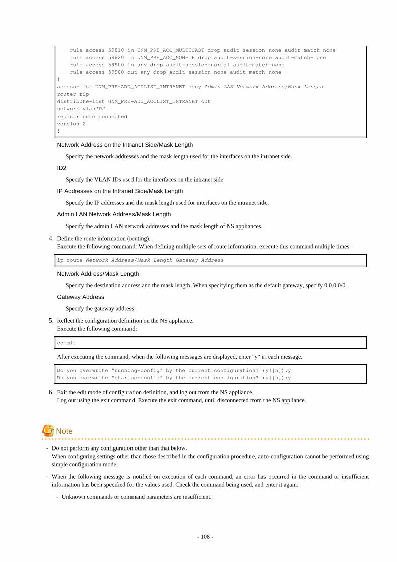
rule access 59810 in UNM_PRE_ACC_MULTICAST drop audit-session-none audit-match-none
rule access 59820 in UNM_PRE_ACC_NON-IP drop audit-session-none audit-match-none
rule access 59900 in any drop audit-session-normal audit-match-none
rule access 59900 out any drop audit-session-none audit-match-none
!
access-list UNM_PRE-ADD_ACCLIST_INTRANET deny Admin LAN Network Address/Mask Lengthrouter rip
distribute-list UNM_PRE-ADD_ACCLIST_INTRANET out
network vlanID2redistribute connected
version 2
!
Network Address on the Intranet Side/Mask Length
Specify the network addresses and the mask length used for the interfaces on the intranet side.
ID2
Specify the VLAN IDs used for the interfaces on the intranet side.
IP Addresses on the Intranet Side/Mask Length
Specify the IP addresses and the mask length used for interfaces on the intranet side.
Admin LAN Network Address/Mask Length
Specify the admin LAN network addresses and the mask length of NS appliances.
4. Define the route information (routing).Execute the following command: When defining multiple sets of route information, execute this command multiple times.
ip route Network Address/Mask Length Gateway Address
Network Address/Mask Length
Specify the destination address and the mask length. When specifying them as the default gateway, specify 0.0.0.0/0.
Gateway Address
Specify the gateway address.
5. Reflect the configuration definition on the NS appliance.Execute the following command:
commit
After executing the command, when the following messages are displayed, enter "y" in each message.
Do you overwrite "running-config" by the current configuration? (y|[n]):y
Do you overwrite "startup-config" by the current configuration? (y|[n]):y
6. Exit the edit mode of configuration definition, and log out from the NS appliance.Log out using the exit command. Execute the exit command, until disconnected from the NS appliance.
Note
- Do not perform any configuration other than that below.When configuring settings other than those described in the configuration procedure, auto-configuration cannot be performed usingsimple configuration mode.
- When the following message is notified on execution of each command, an error has occurred in the command or insufficientinformation has been specified for the values used. Check the command being used, and enter it again.
- Unknown commands or command parameters are insufficient.
- 108 -

- Command incomplete.
C.2.2 Pre-configuration to Use User Customization ModeFor pre-configuration to use user customization mode, perform pre-configuration of the NS Appliance according to the specification ofscripts for automatic configuration (the pre-configuration of a NS Appliance to execute scripts).
When using sample scripts without change, configure the NS Appliance easily using the following procedure:
1. Create an NS appliance pre-configuration file.
For details on the NS appliance pre-configuration file, refer to "2.2.3.4 NS Appliance Pre-configuration File".
2. Execute the rcxnetworkservice preconfig command.
When using the following sample scripts, connect an NS appliance, check control of access from the external network, and modifyconfiguration definitions if necessary.
- Standard model 2 (FW_of_3Tier_sys--NSAppliance2) for firewall deployment
- Standard model 2 (FW_of_sys_inc_SLB_or_not--NSApp1) for firewall and server load balancer deployment
C.3 Server Certificate and CA Certificate OperationsThis section explains the operations necessary for certificates when using an SSL accelerator of the server load balancer function.
When using the SSL accelerator on an NS Appliance whose type is set to integrated network device, register the server certificate and theCA certificate.
NS Appliance supports CA certificates with up to 4,096-bit long keys and server certificates with up to 2,048-bit long keys.
C.3.1 Registering Server Certificates and CA CertificatesThis section explains how to register the certificates necessary when using an SSL accelerator of the server load balancer function.
The tenant user prepares a certificate based on the business system to configure, and the infrastructure administrator registers this certificatein the NS Appliance.
- 109 -
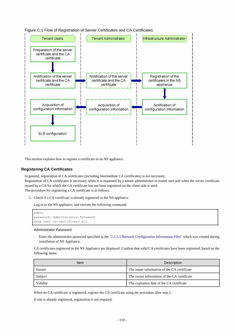
Figure C.1 Flow of Registration of Server Certificates and CA Certificates
This section explains how to register a certificate in an NS appliance.
Registering CA Certificates
In general, registration of CA certificates (including intermediate CA certificates) is not necessary.Registration of CA certificates is necessary when it is requested by a tenant administrator or tenant user and when the server certificateissued by a CA for which the CA certificate has not been registered on the client side is used.The procedure for registering a CA certificate is as follows.
1. Check if a CA certificate is already registered in the NS appliance.
Log in to the NS appliance, and execute the following command:
admin
password: Administrator Passwordshow cert ca-certificate all
Administrator Password
Enter the administrator password specified in the "2.2.3.3 Network Configuration Information Files" which was created duringinstallation of NS Appliance.
CA certificates registered in the NS Appliance are displayed. Confirm that valid CA certificates have been registered, based on thefollowing items:
Item Description
Issuser The issuer information of the CA certificate
Subject The owner information of the CA certificate
Validity The expiration date of the CA certificate
When no CA certificate is registered, register the CA certificate using the procedure after step 2.
If one is already registered, registration is not required.
- 110 -
2. Store the CA certificate in the NS appliance.
Store the certificate in the NS appliance, by transferring an FTP server file to the NS appliance.Store the certificate on the FTP server in advance.Execute the following command:
copy src_uri [ username name [ password password ] ] [ dst_filename ]
src_uri
Specify the certificate on the FTP server as the copy source, in order to copy it to the NS appliance.
ftp://IPv4 address of the FTP server/directory/filename
name
Specify the login ID for the FTP server using a character string containing between 1 and 64 characters.
password
Specify the password for the login ID for the FTP server using a character string containing between 1 and 64 characters.
dst_filename
Specify the file name as "ca-cert.incom.pem".
3. Register the CA certificate in the NS appliance.Execute the following command:
cert entry peer-ca-certificate ca-certificate-group-entry-num
ca-certificate-group-entry-num
Configure the CA certificate number. This number is the number of the peer and the certificate of its own device.A value between 1 and 2048 can be specified.0 has a specific meaning, and certificates from other CA authorities cannot be registered, as the number is allocated to thecertificate created by Resource Orchestrator. Also, the numbers between 1 and 18 are registered for the CA certificates ofSymantec Website Security (formerly VeriSign) installed by default, so use another number.
Registering Server Certificates
1. Store the server certificate in the NS appliance.
Store the certificate in the NS appliance, by transferring an FTP server file to the NS appliance.Store the certificate on the FTP server in advance.Execute the following command:
copy src_uri [ username name [ password password ] ] [ dst_filename ]
src_uri
Specify the certificate on the FTP server as the copy source, in order to copy it to the NS appliance.
ftp://IPv4 address of the FTP server/directory/filename
name
Specify the login ID for the FTP server using a character string containing between 1 and 64 characters.
password
Specify the password for the login ID for the FTP server using a character string containing between 1 and 64 characters.
dst_filename
Specify the file name as "certXXX.imp.pkcs12".
XXX
Entry number
- 111 -
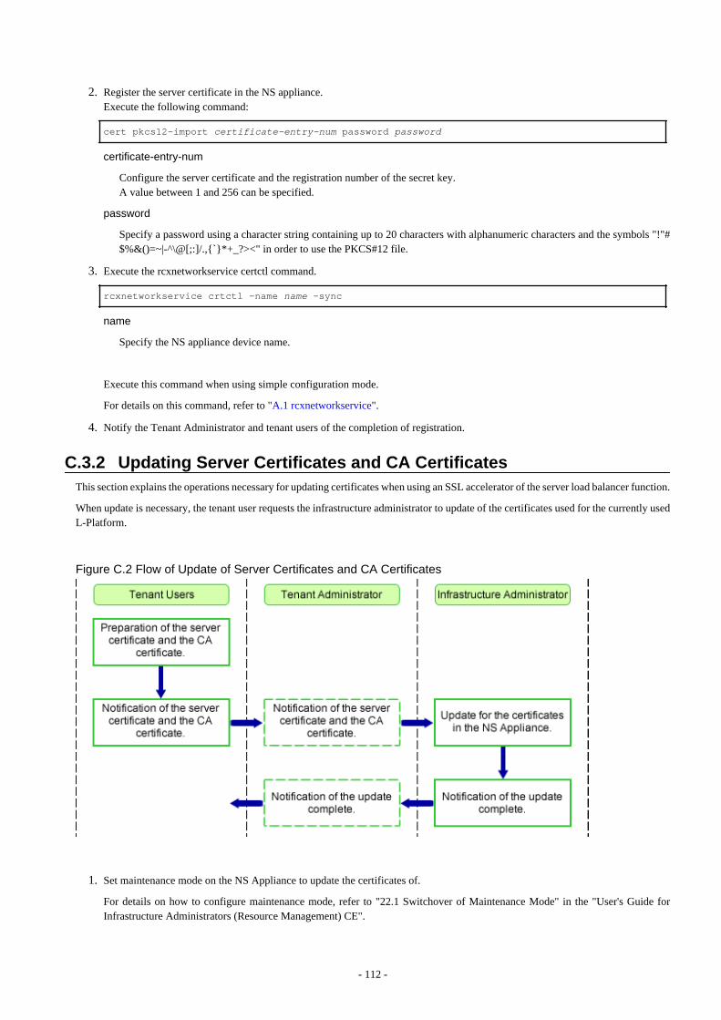
2. Register the server certificate in the NS appliance.Execute the following command:
cert pkcs12-import certificate-entry-num password password
certificate-entry-num
Configure the server certificate and the registration number of the secret key.A value between 1 and 256 can be specified.
password
Specify a password using a character string containing up to 20 characters with alphanumeric characters and the symbols "!"#$%&()=~|-^\@[;:]/.,{`}*+_?><" in order to use the PKCS#12 file.
3. Execute the rcxnetworkservice certctl command.
rcxnetworkservice crtctl -name name -sync
name
Specify the NS appliance device name.
Execute this command when using simple configuration mode.
For details on this command, refer to "A.1 rcxnetworkservice".
4. Notify the Tenant Administrator and tenant users of the completion of registration.
C.3.2 Updating Server Certificates and CA CertificatesThis section explains the operations necessary for updating certificates when using an SSL accelerator of the server load balancer function.
When update is necessary, the tenant user requests the infrastructure administrator to update of the certificates used for the currently usedL-Platform.
Figure C.2 Flow of Update of Server Certificates and CA Certificates
1. Set maintenance mode on the NS Appliance to update the certificates of.
For details on how to configure maintenance mode, refer to "22.1 Switchover of Maintenance Mode" in the "User's Guide forInfrastructure Administrators (Resource Management) CE".
- 112 -

2. Connect to the NS Appliance, and check the CA certificate corresponding to the server certificate of the update target.
This operation is performed when updating the CA certificate.Execute the following command:
admin
password: Administrator Passwordshow cert certificate
show cert certificate Server Certificate Number chain
Administrator Password
Enter the administrator password specified in the "2.2.3.3 Network Configuration Information Files" which was created duringinstallation of NS Appliance.
Server Certificate Number
- When performing auto-configuration using user customization mode
Specify the number of the certificate which is used on the active L-Platform, as notified by the tenant user or tenantadministrator.
- When performing auto-configuration using simple configuration mode
Check and specify the number of the certificate corresponding to the "owner information (CN name)" which was providedby the tenant user or tenant administrator, referring to the results of "show cert certificate".
Confirm that the CA certificate corresponds to the server certificate, using the following item:
Item Description
Chain The certificate chain of the certificate.The registration number of the CA certificate corresponding to the server certificate on the NS Appliance isdisplayed.
3. Delete the server certificate of the update target.
Execute the following command:
cert zeroize cert all Server Certificate Number
Server Certificate Number
Specify the number of the certificate which is used on the active L-Platform, as notified by the tenant user or tenant administrator.
After executing the command, respond with "y" to the output reply message.
4. Register the server certificate of the update target.
Refer to "Registering Server Certificates" in "C.3.1 Registering Server Certificates and CA Certificates".Specify the same certificate number for registration as the server certificate number deleted in step 3.
5. Delete the CA certificate of the update target.
Execute the following command and determine whether updating of the CA certificate corresponding to the server certificate (i.e.the CA certificate with the number confirmed in step 2 is necessary, based on the expiration date.Execute the following command:
show cert certificate Server Certificate Numbershow cert ca-certificate
Server Certificate Number
Specify the number of the CA certificate registered in step 4.
- 113 -
Information
In general, updating of CA certificates is not necessary in the following cases:
- When the issuer information is the same
- When the expiration period of the CA certificate is longer than that of the server certificate to be updated
When updating of the CA certificate is necessary, delete the target CA certificate.For the number of the CA certificate to be deleted, specify the number of the CA certificate for which it was determined that updatingis necessary.When the registration number is between 1 and 18, do not delete the CA certificate.Execute the following command:
cert zeroize ca CA Certificate Number
CA Certificate Number
Specify the number of the CA certificate confirmed in step 2.
After executing the command, respond with "y" to the output reply message.
6. Register the CA certificate of the update target.
Refer to "Registering CA Certificates" in "C.3.1 Registering Server Certificates and CA Certificates". This operation is performedwhen updating the CA certificate.The certificate numbers specified when registering are as follow:
- Specify the same number as the CA certificate deleted in step 5., when deleting the CA certificate (the number of the target CAcertificate is something other than 1 to 18).
- When not deleting the CA certificate (the number of the target CA certificate is 1 to 18), register a new CA certificate.
7. Reflect the update of the certificate on the operating NS Appliance.
Execute the following command:
configure terminal
load running-config
commit
exit
exit
After executing the command, respond with "y" to the output reply message.
8. Execute the rcxnetworkservice certctl command.
rcxnetworkservice crtctl -name name -sync
name
Specify the NS appliance device name.
Execute this command when using the simple configuration mode.
For details on this command, refer to "A.1 rcxnetworkservice".
9. Release the maintenance mode configured when starting operations.
For details on how to release maintenance mode, refer to "22.1 Switchover of Maintenance Mode" in the "User's Guide forInfrastructure Administrators (Resource Management) CE".
- 114 -
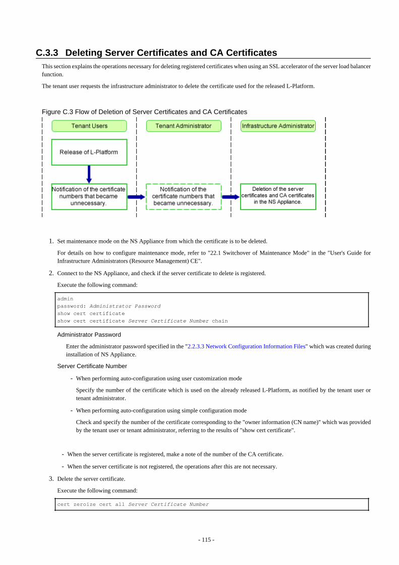
C.3.3 Deleting Server Certificates and CA CertificatesThis section explains the operations necessary for deleting registered certificates when using an SSL accelerator of the server load balancerfunction.
The tenant user requests the infrastructure administrator to delete the certificate used for the released L-Platform.
Figure C.3 Flow of Deletion of Server Certificates and CA Certificates
1. Set maintenance mode on the NS Appliance from which the certificate is to be deleted.
For details on how to configure maintenance mode, refer to "22.1 Switchover of Maintenance Mode" in the "User's Guide forInfrastructure Administrators (Resource Management) CE".
2. Connect to the NS Appliance, and check if the server certificate to delete is registered.
Execute the following command:
admin
password: Administrator Passwordshow cert certificate
show cert certificate Server Certificate Number chain
Administrator Password
Enter the administrator password specified in the "2.2.3.3 Network Configuration Information Files" which was created duringinstallation of NS Appliance.
Server Certificate Number
- When performing auto-configuration using user customization mode
Specify the number of the certificate which is used on the already released L-Platform, as notified by the tenant user ortenant administrator.
- When performing auto-configuration using simple configuration mode
Check and specify the number of the certificate corresponding to the "owner information (CN name)" which was providedby the tenant user or tenant administrator, referring to the results of "show cert certificate".
- When the server certificate is registered, make a note of the number of the CA certificate.
- When the server certificate is not registered, the operations after this are not necessary.
3. Delete the server certificate.
Execute the following command:
cert zeroize cert all Server Certificate Number
- 115 -
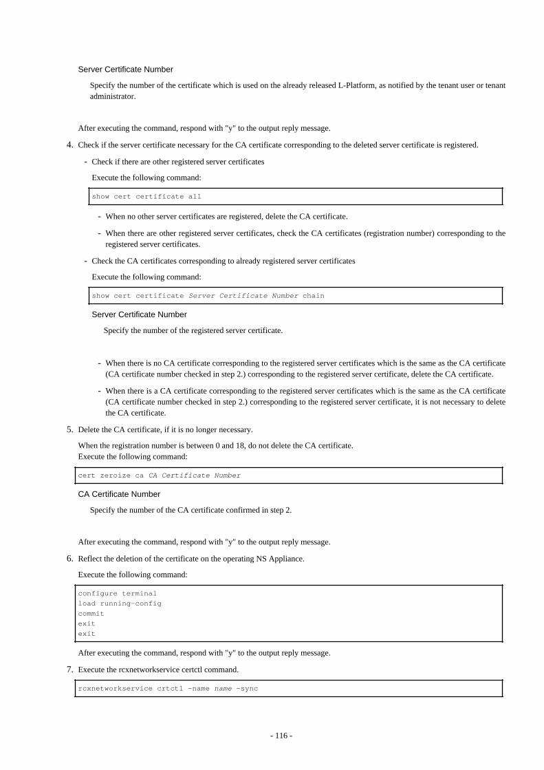
Server Certificate Number
Specify the number of the certificate which is used on the already released L-Platform, as notified by the tenant user or tenantadministrator.
After executing the command, respond with "y" to the output reply message.
4. Check if the server certificate necessary for the CA certificate corresponding to the deleted server certificate is registered.
- Check if there are other registered server certificates
Execute the following command:
show cert certificate all
- When no other server certificates are registered, delete the CA certificate.
- When there are other registered server certificates, check the CA certificates (registration number) corresponding to theregistered server certificates.
- Check the CA certificates corresponding to already registered server certificates
Execute the following command:
show cert certificate Server Certificate Number chain
Server Certificate Number
Specify the number of the registered server certificate.
- When there is no CA certificate corresponding to the registered server certificates which is the same as the CA certificate(CA certificate number checked in step 2.) corresponding to the registered server certificate, delete the CA certificate.
- When there is a CA certificate corresponding to the registered server certificates which is the same as the CA certificate(CA certificate number checked in step 2.) corresponding to the registered server certificate, it is not necessary to deletethe CA certificate.
5. Delete the CA certificate, if it is no longer necessary.
When the registration number is between 0 and 18, do not delete the CA certificate.Execute the following command:
cert zeroize ca CA Certificate Number
CA Certificate Number
Specify the number of the CA certificate confirmed in step 2.
After executing the command, respond with "y" to the output reply message.
6. Reflect the deletion of the certificate on the operating NS Appliance.
Execute the following command:
configure terminal
load running-config
commit
exit
exit
After executing the command, respond with "y" to the output reply message.
7. Execute the rcxnetworkservice certctl command.
rcxnetworkservice crtctl -name name -sync
- 116 -
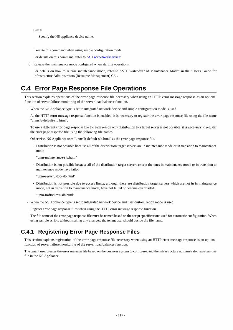
name
Specify the NS appliance device name.
Execute this command when using simple configuration mode.
For details on this command, refer to "A.1 rcxnetworkservice".
8. Release the maintenance mode configured when starting operations.
For details on how to release maintenance mode, refer to "22.1 Switchover of Maintenance Mode" in the "User's Guide forInfrastructure Administrators (Resource Management) CE".
C.4 Error Page Response File OperationsThis section explains operations of the error page response file necessary when using an HTTP error message response as an optionalfunction of server failure monitoring of the server load balancer function.
- When the NS Appliance type is set to integrated network device and simple configuration mode is used
As the HTTP error message response function is enabled, it is necessary to register the error page response file using the file name"unmslb-default-slb.html".
To use a different error page response file for each reason why distribution to a target server is not possible. it is necessary to registerthe error page response file using the following file names.
Otherwise, NS Appliance uses "unmslb-default-slb.html" as the error page response file.
- Distribution is not possible because all of the distribution target servers are in maintenance mode or in transition to maintenancemode
"unm-maintenance-slb.html"
- Distribution is not possible because all of the distribution target servers except the ones in maintenance mode or in transition tomaintenance mode have failed
"unm-server_stop-slb.html"
- Distribution is not possible due to access limits, although there are distribution target servers which are not in in maintenancemode, not in transition to maintenance mode, have not failed or become overloaded
"unm-trafficlimit-slb.html"
- When the NS Appliance type is set to integrated network device and user customization mode is used
Register error page response files when using the HTTP error message response function.
The file name of the error page response file must be named based on the script specifications used for automatic configuration. Whenusing sample scripts without making any changes, the tenant user should decide the file name.
C.4.1 Registering Error Page Response FilesThis section explains registration of the error page response file necessary when using an HTTP error message response as an optionalfunction of server failure monitoring of the server load balancer function.
The tenant user creates the error message file based on the business system to configure, and the infrastructure administrator registers thisfile in the NS Appliance.
- 117 -

Figure C.4 Registration Flow of Error Page Files
Registration of Error Page Files
1. Connect to the NS Appliance and store the error page file on the NS appliance.
Store the error page file of the NS appliance by transferring it to the NS applianceStore the error page file on the FTP server beforehand.Execute the following command:
copy src_uri [ username name [ password password ] ] [ dst_filename ]
src_uri
Specify the file on the FTP server as the copy source, in order to copy it to the NS appliance.
ftp://IPv4 address of the FTP server/directory/filename
name
Specify the login ID for the FTP server using a character string containing between 1 and 64 characters.
password
Specify the password for the login ID for the FTP server using a character string containing between 1 and 64 characters.
dst_filename
When using simple configuration mode
According to the content of the error page response file, specify the following file name:
[Default Error Page Response File]
Specify the file name as "unmslb-default-slb.html".
[The error page response file used when distribution is not possible because all of the distribution target servers are inmaintenance mode or in transition to maintenance mode]
Specify the file name as "unm-maintenance-slb.html".
- 118 -
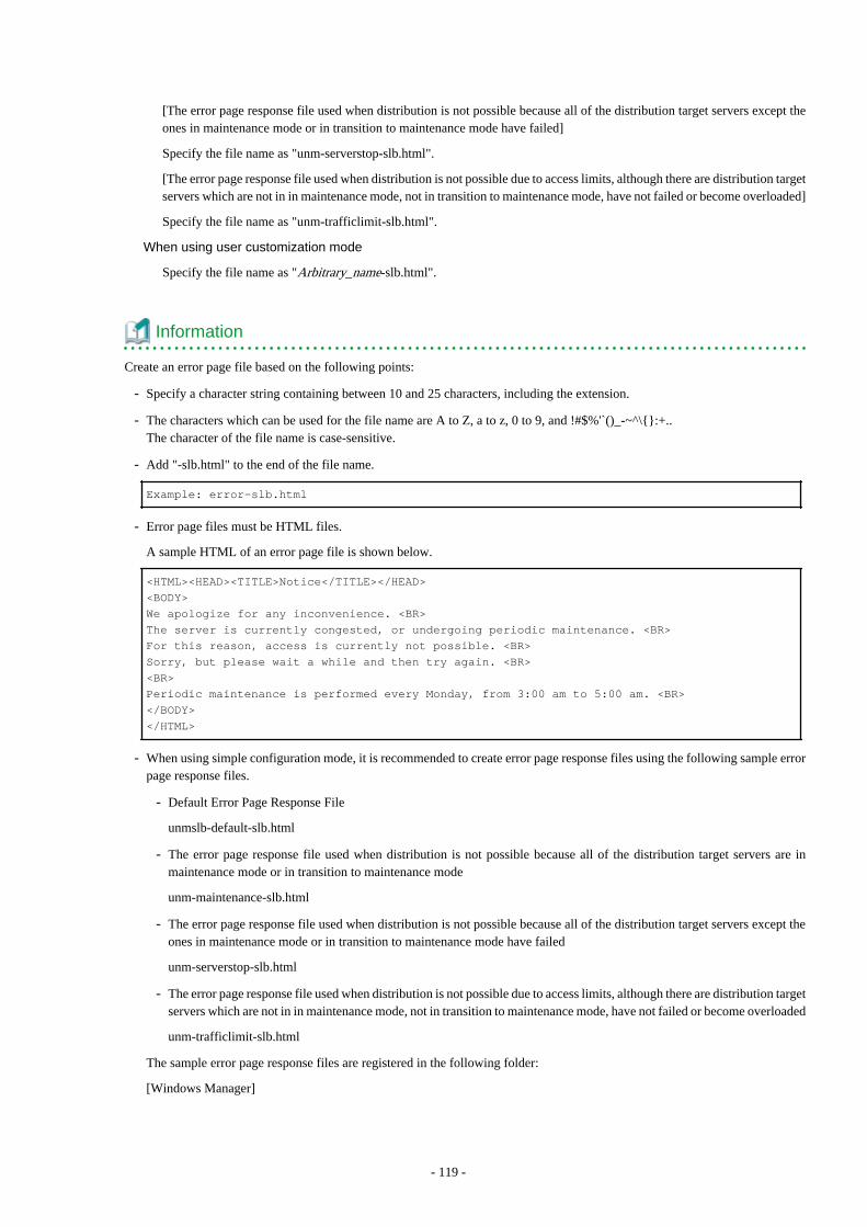
[The error page response file used when distribution is not possible because all of the distribution target servers except theones in maintenance mode or in transition to maintenance mode have failed]
Specify the file name as "unm-serverstop-slb.html".
[The error page response file used when distribution is not possible due to access limits, although there are distribution targetservers which are not in in maintenance mode, not in transition to maintenance mode, have not failed or become overloaded]
Specify the file name as "unm-trafficlimit-slb.html".
When using user customization mode
Specify the file name as "Arbitrary_name-slb.html".
Information
Create an error page file based on the following points:
- Specify a character string containing between 10 and 25 characters, including the extension.
- The characters which can be used for the file name are A to Z, a to z, 0 to 9, and !#$%'`()_-~^\{}:+..The character of the file name is case-sensitive.
- Add "-slb.html" to the end of the file name.
Example: error-slb.html
- Error page files must be HTML files.
A sample HTML of an error page file is shown below.
<HTML><HEAD><TITLE>Notice</TITLE></HEAD>
<BODY>
We apologize for any inconvenience. <BR>
The server is currently congested, or undergoing periodic maintenance. <BR>
For this reason, access is currently not possible. <BR>
Sorry, but please wait a while and then try again. <BR>
<BR>
Periodic maintenance is performed every Monday, from 3:00 am to 5:00 am. <BR>
</BODY>
</HTML>
- When using simple configuration mode, it is recommended to create error page response files using the following sample errorpage response files.
- Default Error Page Response File
unmslb-default-slb.html
- The error page response file used when distribution is not possible because all of the distribution target servers are inmaintenance mode or in transition to maintenance mode
unm-maintenance-slb.html
- The error page response file used when distribution is not possible because all of the distribution target servers except theones in maintenance mode or in transition to maintenance mode have failed
unm-serverstop-slb.html
- The error page response file used when distribution is not possible due to access limits, although there are distribution targetservers which are not in in maintenance mode, not in transition to maintenance mode, have not failed or become overloaded
unm-trafficlimit-slb.html
The sample error page response files are registered in the following folder:
[Windows Manager]
- 119 -
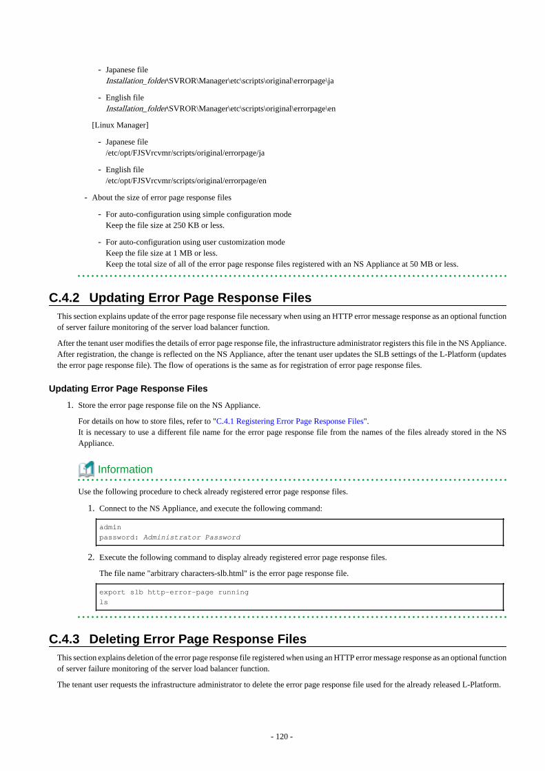
- Japanese fileInstallation_folder\SVROR\Manager\etc\scripts\original\errorpage\ja
- English fileInstallation_folder\SVROR\Manager\etc\scripts\original\errorpage\en
[Linux Manager]
- Japanese file/etc/opt/FJSVrcvmr/scripts/original/errorpage/ja
- English file/etc/opt/FJSVrcvmr/scripts/original/errorpage/en
- About the size of error page response files
- For auto-configuration using simple configuration modeKeep the file size at 250 KB or less.
- For auto-configuration using user customization modeKeep the file size at 1 MB or less.Keep the total size of all of the error page response files registered with an NS Appliance at 50 MB or less.
C.4.2 Updating Error Page Response FilesThis section explains update of the error page response file necessary when using an HTTP error message response as an optional functionof server failure monitoring of the server load balancer function.
After the tenant user modifies the details of error page response file, the infrastructure administrator registers this file in the NS Appliance.After registration, the change is reflected on the NS Appliance, after the tenant user updates the SLB settings of the L-Platform (updatesthe error page response file). The flow of operations is the same as for registration of error page response files.
Updating Error Page Response Files
1. Store the error page response file on the NS Appliance.
For details on how to store files, refer to "C.4.1 Registering Error Page Response Files".It is necessary to use a different file name for the error page response file from the names of the files already stored in the NSAppliance.
Information
Use the following procedure to check already registered error page response files.
1. Connect to the NS Appliance, and execute the following command:
admin
password: Administrator Password
2. Execute the following command to display already registered error page response files.
The file name "arbitrary characters-slb.html" is the error page response file.
export slb http-error-page running
ls
C.4.3 Deleting Error Page Response FilesThis section explains deletion of the error page response file registered when using an HTTP error message response as an optional functionof server failure monitoring of the server load balancer function.
The tenant user requests the infrastructure administrator to delete the error page response file used for the already released L-Platform.
- 120 -
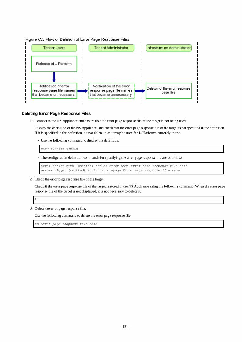
Figure C.5 Flow of Deletion of Error Page Response Files
Deleting Error Page Response Files
1. Connect to the NS Appliance and ensure that the error page response file of the target is not being used.
Display the definition of the NS Appliance, and check that the error page response file of the target is not specified in the definition.If it is specified in the definition, do not delete it, as it may be used for L-Platforms currently in use.
- Use the following command to display the definition.
show running-config
- The configuration definition commands for specifying the error page response file are as follows:
error-action http (omitted) action error-page Error page response file nameerror-trigger (omitted) action error-page Error page response file name
2. Check the error page response file of the target.
Check if the error page response file of the target is stored in the NS Appliance using the following command: When the error pageresponse file of the target is not displayed, it is not necessary to delete it.
ls
3. Delete the error page response file.
Use the following command to delete the error page response file.
rm Error page response file name
- 121 -

Index[R]
rcxadm nsoptctl.......................................................................101rcxnetworkservice.....................................................................92
- 122 -


![Overview - Fujitsusoftware.fujitsu.com/jp/manual/manualfiles/m170000/j2x17770/03enz...[Citrix Xen] Sections related to ... the examples assume OSs up to Windows 7 and Windows Server](https://img.dokumen.tips/doc/110x75/5b02ccf77f8b9a2e228b6efa/overview-citrix-xen-sections-related-to-the-examples-assume-oss-up-to-windows.jpg)