Embed Size (px)
Citation preview

Printed in Canada
Service Bulletin No. 3059MODEL TYPE SECTION/GROUP DATE
SUBJECT
CONDITIONS
MAY 31, 2011D Series Coaches Service Information 7--Electrical
ACTIA MULTIPLEX SYSTEM (MUX)
Parts may be purchased from MCI Service Parts, Louisville, Kentucky.
Description:MCI is now offering the Actia Multiplex System as an option on 2010 Dmodel coaches, beginning with unit 59587. Themultiplex system increases the harness reliability, decreasing the number of circuits, electrical connectors, terminals,and splices. Actia Multiplex System also features a 7-inch LCD monitor installed in multiple locations based on coachconfiguration for technicians to use for onboard system diagnostics and repair. This Service Bulletin providesillustrations anddescriptions related to the systemcomponents, location, operation, anddiagnostics. For further systeminformation refer to applicable maintenance manual.
NOTICEAcronym definitions are found in the Glossary at the end of this document.
PartsQty. New P/N Description1 07---08---3291 Gauge--- Speedometer, 85 MPH1 07---08---3292 Gauge --- Four-In-One1 07---08---3293 Gauge--- Gauge --- Voltmeter1 07---08---3294 Gauge --- Transmission Temp1 07---08---3295 Gauge --- Fuel1 07---08---3296 Lamp --- Warning, Left Hand1 07---08---3297 Lamp --- Warning, Right Hand1 07---08---3301 Switch --- Hazard4 07---08---3316 Fuse --- Marine Rated Battery Fuse (MRBF) 75A2 07---08---3317 Fuse --- Marine Rated Battery Fuse (MRBF) 100A1 07---08---3303 Switch --- Start3 07---08---3832 Box --- Fuse, Dual Vehicle Electrical Center (DVEC)1 07---13---2394 Light Emitting Diode (LED) --- Red, 24VDC, Front Panel Mounted1 07---08---3952 Switch --- Kneeling1 07---08---3353 Switch --- Entrance Door2 07---08---3377 Circuit Breaker (CB) --- Manual Reset --- 80 A4 07---08---3520 Module --- Power Management Module (PMM)1 07---08---3552 Display --- 7” Liquid Crystal Display (LCD), Diagnostics1 07---12---3507 Harness---P/R Interface, Actia1 07---08---3573 Switch ---Chime1 07---08---3577 Switch---Engine Brake---Fast Idle1 07---08---3578 Switch---Parcel Rack Blowers---Aux Heat1 07---08---3579 Switch---LH Blind---RH Blind---Parcel Rack Blowers---Aux Heat1 07---08---3575 Switch---Engine Brake---Fast Idle

Printed in Canada
PAGEDATE 2MAY 31, 2011Service Bulletin No. 3059Parts (CONT.)Qty. New P/N Description1 07---08---3577 Switch---Engine Brake---Fast Idle1 07---08---3589 Switch---Engine Brake---Fast Idle1 07---08---3569 Switch--- Interior Lights, Front Lights, Reading Lights, Dimmer Reading Lights1 07---08---3570 Switch---Panel Lights, Driver Light, Dome Light1 07---08---3571 Switch---Panel Lights, Driver Light, Dome Light, Fog Lights1 07---08---3572 Switch---Tag Axle, Rear Rise, Automatic Traction Control (ATC)1 07---80---3574 Switch---110V---Chime---External Speaker1 07---08---3575 Switch---Engine Brake---Fast Idle1 07---08---3576 Switch---Cruise On/Off---Cruise Set/Resume---Engine Brake---Fast Idle1 07---08---3745 Switch---110 Volt ---Chime1 07---08---3789 Switch---Cruise On/Off---Cruise Set/Resume---Retarder---Fast Idle1 07---08---3576 Switch---Rear Rise---Automatic Traction Control (ATC)
Service Information:1. New parts will be available for service replacement.
Service Procedure:
General notesThis bulletin is for information only.
Use Safe Shop Practices At All Times.
System and Components
The ACTIA system consists of the following:
S PMM (Power Management Modules)
S Multiplexed Dash Switches
S Multiplexed Dash Gauges
S Multiplexed Left Hand and Right Hand Telltale Clusters
S LCD (Liquid Crystal Display) Diagnostic Interface
S DVEC (Dual Voltage Electrical Center) Modules

Printed in Canada
PAGEDATE 3MAY 31, 2011Service Bulletin No. 3059
Figure 1. Power Management Module (PMM1), Left Front Service Door
Figure 2. ESC ECU, PMM2, DVEC, Right Front Baggage Bay
Item Description
1 ESC (Electronic Stability Control ECU (Electronic Control Unit)
2 PMM2 (Power Management Module 2)
3 DVEC (Dual Vehicle Electrical Center)

Printed in Canada
PAGEDATE 4MAY 31, 2011Service Bulletin No. 3059
Figure 3. Diagnostic Plug, Ignition Bypass, PMM 3 and 4, Left Rear Baggage Bay
Item Description
1 Diagnostic Plug, Ignition Bypass Switch
2 PMM 4, HVAC Controller
3 PMM 3, Transmission ECU (Electronic Control Unit), DVEC Module
4 DVEC (Dual Vehicle Electrical Center)

Printed in Canada
PAGEDATE 5MAY 31, 2011Service Bulletin No. 3059
Battery Compartment Updates
Figure 4. Battery Compartment and Manual Reset Breakers
Item Description
1 Battery Rotary Disconnect Switch
2 Manual Reset Circuit Breaker
Figure 5. New Rear Remote J Box, Engine Compartment
Item Description
1 LED Generator Lamps
2 Diagnostic Connector

Printed in Canada
PAGEDATE 6MAY 31, 2011Service Bulletin No. 3059
Figure 6. Front J Box
Item Description
1 LCD Diagnostic Interface
2 DVEC Module
Circuit Numbering
Description Ckt # range Old ckt # rangeEngine --- Trans 00000 --- 09999 0 --- 1999Starting and Charging 20000 --- 24999 2000 --- 2999HVAC & Aux Heaters 30000 --- 49999 3000 --- 4999Systems --- ABS, Kneeling,WCL
50000 --- 69999 5000 --- 6999
Lighting --- Exterior, Interior 70000 --- 84999 7000 --- 8499Accessories---Mirrors,Entertainment
85000 --- 89999 8500 --- 8999
Accessories --- ParcelRack Entertainment
90000 --- 99999 9000 --- 9999
Circuit numbers follow the following rules:1. Base of circuit number is 5 digits.2. Adding a letter designation to circuit for supply wires (1999A).3. Adding a numerical designation for ground wires (199991).4. All wires follow the following color coding:
S Chassis Ground --- White (WH)S Isolated Ground --- Brown (BR)S 24V --- Red (RD)S 12V --- Blue (BL)S Signal --- Black (BK)

Printed in Canada
PAGEDATE 7MAY 31, 2011Service Bulletin No. 30595. All wires going to transmission and engine connectors follow vendor specification for circuit numberlabeling.
6. Wire gauge and color are specified on the schematic.7. A prefix indicating which harness the wire is in will precede the circuit number. (ex. CT 1999A).8. J1939 cables include the CAN bus they are a part of, as well as, the cable number within that bus. (ex. acable 1 on can 2 should be labeled CBL01_02).
9. CAN bus takeoffs are color coded for quick reference to the CAN bus they belong to:S Orange---CAN 0S Yellow---CAN 1S Green---CAN 2
Figure 7. Typical New Instrument Panel Layout
Note: Switch layout and features are subject to change based on coach configuration.
Item Description Item Description
1 INTERIOR LIGHTS 17 COOLANT TEMP
2 FRONT ENTRANCE LIGHTS 18 VENT
3 READING LIGHTS 19 DRIVER’S FAN (DEFROST)
4 DIMMER READING LIGHTS (VAR) 20 HVAC CONTROL PANEL
5 ENGINE BRAKE 21 REAR AIR PRESSURE
6 FAST IDLE 22 FRONT AIR PRESSURE
7 TAG AXLE (Option) 23 PROVISION FOR OPTION
8 REAR RISE 24 VOLTMETER
9 ATC (AUTOMATIC TRACTION CONTROL) 25 TRANSMISSION TEMP (Option)
10 CRUISE CONTROL (Option for D Commuter Coach) 26 KEYED IGNITION PROVISION
11 SET/COAST RESUME/ACCEL (Option for D CommuterCoach)
27 DEF GAUGE
12 WCL MASTER 28 FUEL GAUGE (Option)
13 LIGHTER 29 PA SYSTEM
14 WARNING BANKS (Telltales) 30 SMART TIRE (Option)
15 SPEEDOMETER 31 NotShown
WINDSHIELD WIPERS & WASHER(Moved to the steering column stalk)
16 OIL PRESSURE 32 NotShown
AUTO TRANS SHIFT SELECTOR(Moved to the LH console)
Printed in Canada
PAGEDATE 8MAY 31, 2011Service Bulletin No. 3059
Figure 8. Typical Driver’s Console Switch Layout
Note: Switch layout and features are subject to change based on coach configuration.
Item Description Item Description
1 ENGINE OVERRIDE 14 CHIME
2NotShown
FAST IDLE (Moved to Dash) 15 NotShown
READING LIGHT DIMMER (Moved to Dash)
3 ENGINE START 16 EXTERNAL SPEAKER (Option)
4 AUXILIARY HEAT (Option) 17 NotShown
REAR RISE (Moved to Dash)
5 HAZARD 18 NotShown
TAG AXLE (Moved to Dash)---(Option)
6 KNEEL 19 PANEL ILLUMINATION
7 DOME LIGHTS 20 110 VOLT SWITCH (Option)
8 NotShown
INTERIOR LIGHTS (Moved to Dash) 21 ENTRANCE DOOR SWITCH
9 DRIVER’S LIGHT 22 PROVISION FOR OPTION
10 PARCEL RACK BLOWERS 23 MIRROR CONTROL PAD
11 NotShown
FRONT ENTRANCE LIGHTS (Moved to Dash) 24 MASTER RUN
12 NotShown
TEST---READING LIGHTS (Moved to Dash) 25 BEVERAGE HOLDER
13 NotShown
ENGINE BRAKE (Moved to Dash) 26 BLANK SWITCH
There are three toggle switches, Entrance Door, Kneel, and Engine Override.
Printed in Canada
PAGEDATE 9MAY 31, 2011Service Bulletin No. 3059
Actia Multiplexed Components
Figure 9. Power Management Module (PMM)
The Power Management Module (PMM) performs the load switching.
Figure 10. Multiplexed Dash Switches
The rocker switches use optical interrupts and therefore require no contacts.Powered by 12V, the icons are amber andthe slits are green. The panel assembly is waterproof.

Printed in Canada
PAGEDATE 10MAY 31, 2011Service Bulletin No. 3059
Figure 11. Multiplexed Dash Switches
Poweredby 12V, the icons are amber and the slits are green. Eachmodule has its ownsource address on theCAN2Chassisdata bus. The ON/OFF switch status of each switch is sent on the data bus once each second and at any switch change.

Printed in Canada
PAGEDATE 11MAY 31, 2011Service Bulletin No. 3059
Figure 12. Multiplexed Dash Gauges
Item Description
1 Speedometer
2 4 in 1 Gauge
3 Transmission Temperature Gauge
4 Voltmeter
Multiplexed J1939 Gauges, Standard Gauge sizes 117mm and 52mm,117mm Master gauge with built--in messagecenter. 117mmmulti--gauge; a 4 in 1 (shown), 52mm individual gauges for Fuel, Transmission Temp, Voltmeter, DEF level(2010 EPA).

Printed in Canada
PAGEDATE 12MAY 31, 2011Service Bulletin No. 3059
Figure 13. Multiplexed LH and RH Telltale Clusters
The telltale modules are data driven slave devices controlled by the speedometer.
Figure 14. LCD (Liquid Crystal Display) Diagnostic Interface
Diagnostic Display gives one location to view operation of many systems on the coach. The 7” diagonal color LCDtouch screen with display 800 x 480 screen resolution is capable of 262,144 colors. The LCD has a CAN J1939Multiplexed controller with master programmer and controller functionality, monitoring Powertrain CAN 1 and ChassisCAN 2.

Printed in Canada
PAGEDATE 13MAY 31, 2011Service Bulletin No. 3059
Figure 15. DVEC Module
Dual Vehicle Electrical Centers (DVEC) are the power distribution modules. The D--coach has 3 DVECmodules and allare identical. DVEC accepts standard automotive components including fuses, relays, circuit breakers, diodes, and otherdevices that have 2.8mm wide terminals on 8.1mm centerline spacing. The inputs (connector or stud) and outputs(connector) of the DVEC are color--coded and keyed, and provide quick installation and ease of service.
Figure 16. Actia Multiplexing Network Architecture CAN 0
CAN 0 is proprietary and is used exclusively for inter-module communication.

Printed in Canada
PAGEDATE 14MAY 31, 2011Service Bulletin No. 3059
Figure 17. Actia Multiplexing Network Architecture CAN 1
CAN 1 is the power train CAN channel. Corresponds to pins C and D on the round, diagnostic connector.
Figure 18. Actia Multiplexing Network Architecture CAN 2
CAN 2 is the chassis CAN channel used for communication among the PMM’s, MUX switch, speedometer, and otherdevices. Corresponds to pins H and J on the round, diagnostic connector. Each PMM has a gateway built in and PMM3serves as the gateway between the power train and coach CAN lines.
Printed in Canada
PAGEDATE 15MAY 31, 2011Service Bulletin No. 3059
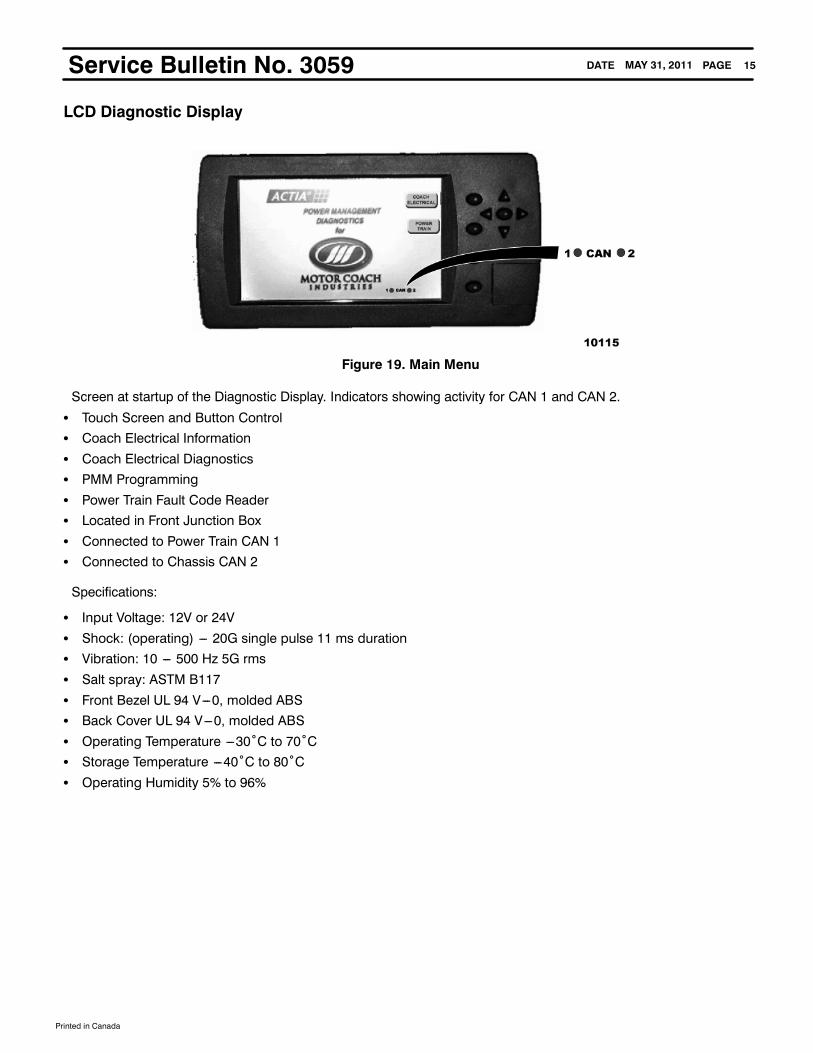
LCD Diagnostic Display
Figure 19. Main Menu
Screen at startup of the Diagnostic Display. Indicators showing activity for CAN 1 and CAN 2.
S Touch Screen and Button ControlS Coach Electrical InformationS Coach Electrical DiagnosticsS PMM ProgrammingS Power Train Fault Code ReaderS Located in Front Junction BoxS Connected to Power Train CAN 1S Connected to Chassis CAN 2
Specifications:
S Input Voltage: 12V or 24VS Shock: (operating) --- 20G single pulse 11 ms durationS Vibration: 10 --- 500 Hz 5G rmsS Salt spray: ASTM B117S Front Bezel UL 94 V---0, molded ABSS Back Cover UL 94 V---0, molded ABSS Operating Temperature ---30˚C to 70˚CS Storage Temperature ---40˚C to 80˚CS Operating Humidity 5% to 96%
Printed in Canada
PAGEDATE 16MAY 31, 2011Service Bulletin No. 3059
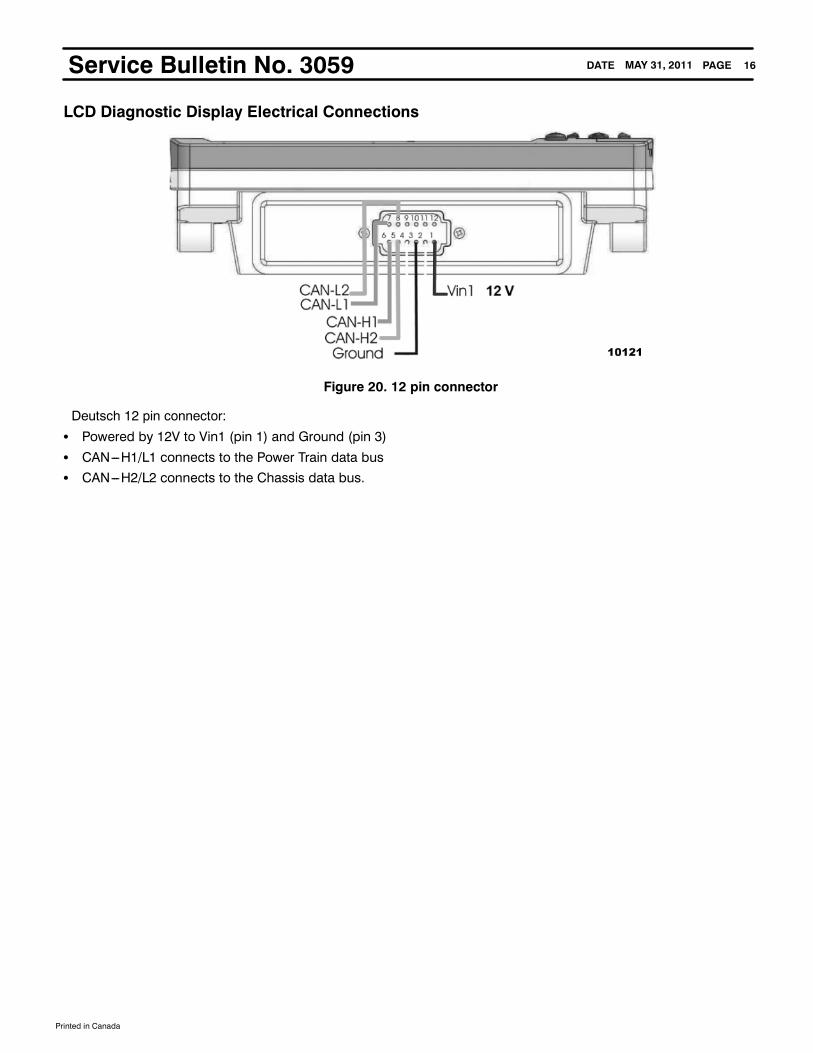
LCD Diagnostic Display Electrical Connections
Figure 20. 12 pin connector
Deutsch 12 pin connector:
S Powered by 12V to Vin1 (pin 1) and Ground (pin 3)S CAN---H1/L1 connects to the Power Train data busS CAN---H2/L2 connects to the Chassis data bus.

Printed in Canada
PAGEDATE 17MAY 31, 2011Service Bulletin No. 3059
Figure 21. View PMM Information
Selecting COACH ELECTRICAL displays information from the four PMMs:
S The Serial number is listed next.S A description of the PMM location.S The bottom line shows the V1 and V2 voltages seen at each PMM.S Note: PMM2 has V1 = 12V while V2 = 24. All other PMMs have V1 and V2 = 24V.
Figure 22. View PMM I/O
This screen shows all inputs and output status for the selected PMM. V1 andV2 voltages are also shown as is CANdatabus status. Each PMM can be selected using the buttons across the top. Selecting INPUT and OUTPUT gives additionalinformation for the INPUTS and OUTPUTS.

Printed in Canada
PAGEDATE 18MAY 31, 2011Service Bulletin No. 3059
Figure 23. View PMM I/O Inputs
This screen shows the INPUT detail. The voltage or resistance seen by the input is displayed. The logic status is shownby the green or gray icon.
The INPUT’s configuration:
S SP = Special --- Address input.S HS = High side input V>4V for logic green.S LS = Low side input V<4V for logic green.S AN = Analog; could have a voltage indication or ohm; If built-in current source is selected then resistance will be shown.
Use the scroll buttons to view all 29 of the inputs. The OUTPUT screen can be directly selected or BACK goes to theVIEW PMM I/O screen.
Figure 24. View PMM I/O
Back to the View screen and selecting OUTPUTS goes to the OUTPUT DETAIL screen.
Printed in Canada
PAGEDATE 19MAY 31, 2011Service Bulletin No. 3059
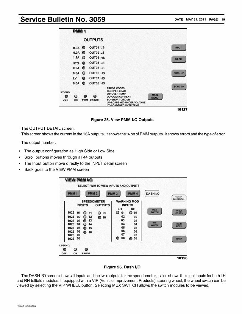
Figure 25. View PMM I/O Outputs
The OUTPUT DETAIL screen.This screen shows the current in the13Aoutputs. It shows the%onof PMMoutputs. It shows errors and the type of error.
The output number:
S The output configuration as High Side or Low SideS Scroll buttons moves through all 44 outputsS The Input button move directly to the INPUT detail screenS Back goes to the VIEW PMM screen
Figure 26. Dash I/O
TheDASH I/O screen shows all inputs and the twooutputs for the speedometer, it also shows theeight inputs for both LHand RH telltale modules. If equipped with a VIP (Vehicle Improvement Products) steering wheel, the wheel switch can beviewed by selecting the VIP WHEEL button. Selecting MUX SWITCH allows the switch modules to be viewed.

Printed in Canada
PAGEDATE 20MAY 31, 2011Service Bulletin No. 3059
Figure 27. Mux Switch View
Item Description
1 Switch Source Address
2 Gray (Indicator Color)---OFF
3 Green (Indicator Color)---ON
4 Red (Indicator Color)---ERROR NOTE: In this example, there are no ERROR indicators displayed.
This screen indicates the status of eachmultiplex switch found on the data bus. The green indicator color represents thesideof the rocker that is pressed. Additional informationgiven is the sourceaddress of each switchmodule. There are 16SAavailable in the system and all switchmodulesmay not appear onONE screen. To viewadditional modules, pressMORE toadvance to thenext screen. Inactive switcheswill haveall eight round icons gray. Flippinga switch is theeasiest way to findaparticular switch module. The SA can be found on the switch module label or in the application program.
Power Train Fault Codes
Figure 28. Power Train Faults
Printed in Canada
PAGEDATE 21MAY 31, 2011Service Bulletin No. 3059
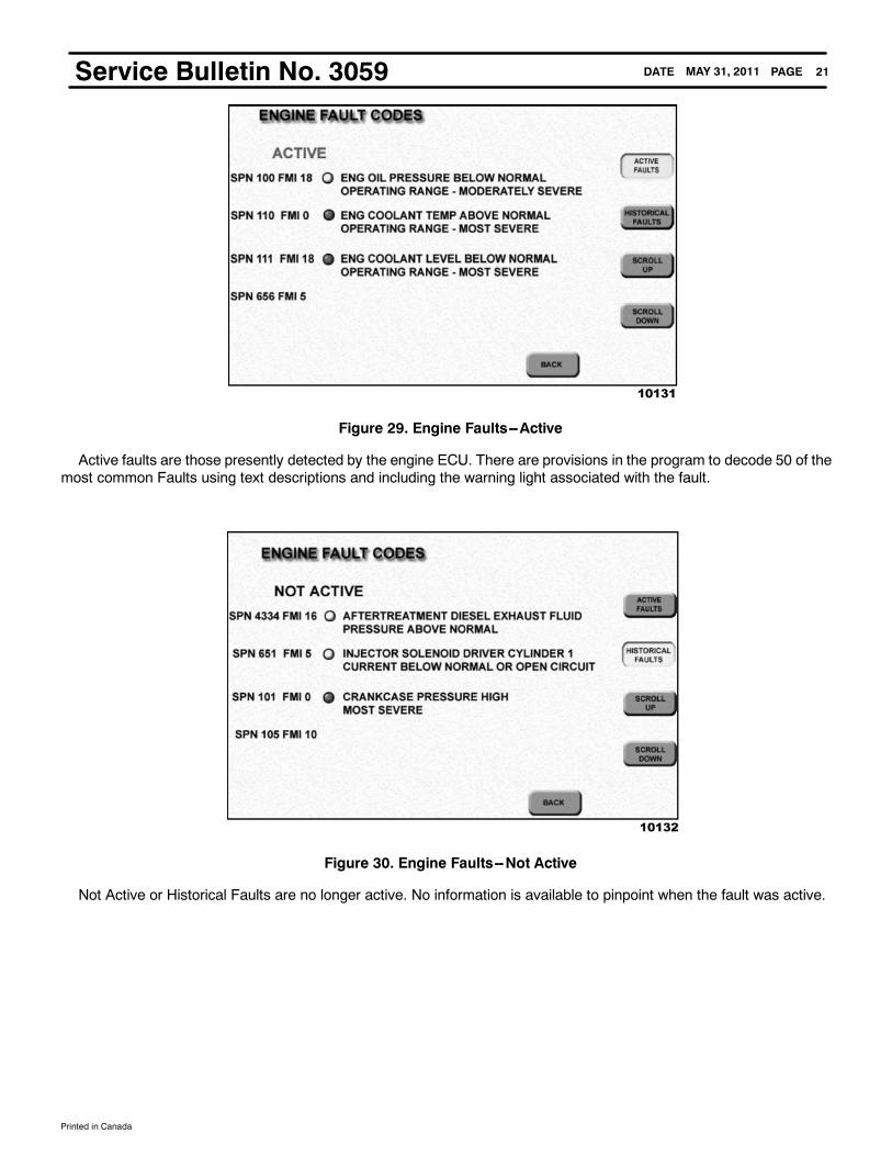
Figure 29. Engine Faults--Active
Active faults are those presently detected by the engine ECU. There are provisions in the program to decode 50 of themost common Faults using text descriptions and including the warning light associated with the fault.
Figure 30. Engine Faults--Not Active
Not Active or Historical Faults are no longer active. No information is available to pinpoint when the fault was active.

Printed in Canada
PAGEDATE 22MAY 31, 2011Service Bulletin No. 3059
Figure 31. Power Train Faults
Transmission faults display much like Engine faults as do ABS and Tire Pressure faults.
Figure 32. Transmission Faults--Active
Active Transmission faults.
Printed in Canada
PAGEDATE 23MAY 31, 2011Service Bulletin No. 3059
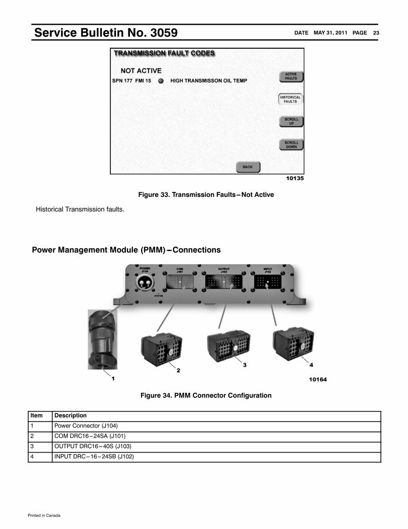
Figure 33. Transmission Faults--Not Active
Historical Transmission faults.
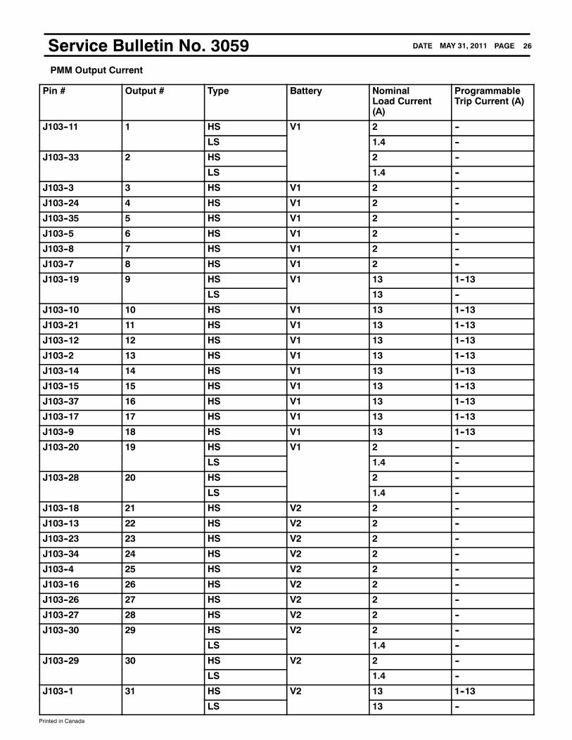
Power Management Module (PMM)---Connections
Figure 34. PMM Connector Configuration
Item Description
1 Power Connector (J104)
2 COM DRC16---24SA (J101)
3 OUTPUT DRC16---40S (J103)
4 INPUT DRC---16---24SB (J102)

Printed in Canada
PAGEDATE 24MAY 31, 2011Service Bulletin No. 3059Connectors 2 and 4 are both 24 pin and each is keyed so they cannot be swapped (SA & SB). Connector 3 is a 40 pin
connector. Connector 1 is the power connector and has a bayonet latch. While each connector is labeled with its primaryfunction, only the output connector contain purely outputs as seen in the pinout charts.
PMM Pinout Connectors 2, 4, and 1
POWER COM INPUT
J104 J101 J102
Pin Name Pin Name Pin Name Address
A V1 1 CAN 0 -- 1 Input 1 1
B V2 2 CAN 0 + 2 Input 2 2
3 CAN 0 shield 3 Input 3 3
4 CAN 1 -- 4 Input 4 4
5 CAN 1 + 5 Input 5 5
6 CAN 1 shield 6 Input 6 6
7 CAN 2 -- 7 Input 7 7
8 CAN 2 + 8 Input 8 8
9 CAN 2 shield 9 Input 9
10 RS485 +(J1708 +)
10 Input 10
11 Input 24 11 Input 11
12 Input 25 12 Input 12
13 Input 26 13 Input 13
14 Input 27 14 Input 14
15 Input 28 15 Input 15
16 RS485 --(J1708 --)
16 Input 16
17 Input 29 17 Input 17
18 GND 18 Input 18
19 + 5V 19 Input 19
20 GND 20 Input 20
21 GND 21 Input 21
22 Output 41 22 Input 22
23 Output 42 23 Input 23
24 Output 43 24 Address Out

Printed in Canada
PAGEDATE 25MAY 31, 2011Service Bulletin No. 3059PMM Pinout Connector 3
OUTPUT
J103
Pin Name Pin Name
1 Output 31 21 Output 11
2 Output 13 22 Output 33
3 Output 3 23 Output 23
4 Output 25 24 Output 4
5 Output 6 25 Output 35
6 Output 36 26 Output 27
7 Output 8 27 Output 28
8 Output 7 28 Output 20
9 Output 18 29 Output 30
10 Output 10 30 Output 29
11 Output 1 31 Output 32
12 Output 12 32 Output 34
13 Output 22 33 Output 2
14 Output 14 34 Output 24
15 Output 15 35 Output 5
16 Output 26 36 Output 37
17 Output 17 37 Output 16
18 Output 21 38 Output 38
19 Output 9 39 Output 39
20 Output 19 40 Output 40
Printed in Canada
PAGEDATE 26MAY 31, 2011Service Bulletin No. 3059PMM Output Current
Pin # Output # Type Battery NominalLoad Current(A)
ProgrammableTrip Current (A)
J103--11 1 HS V1 2 --
LS 1.4 --
J103--33 2 HS 2 --
LS 1.4 --
J103--3 3 HS V1 2 --
J103--24 4 HS V1 2 --
J103--35 5 HS V1 2 --
J103--5 6 HS V1 2 --
J103--8 7 HS V1 2 --
J103--7 8 HS V1 2 --
J103--19 9 HS V1 13 1--13
LS 13 --
J103--10 10 HS V1 13 1--13
J103--21 11 HS V1 13 1--13
J103--12 12 HS V1 13 1--13
J103--2 13 HS V1 13 1--13
J103--14 14 HS V1 13 1--13
J103--15 15 HS V1 13 1--13
J103--37 16 HS V1 13 1--13
J103--17 17 HS V1 13 1--13
J103--9 18 HS V1 13 1--13
J103--20 19 HS V1 2 --
LS 1.4 --
J103--28 20 HS 2 --
LS 1.4 --
J103--18 21 HS V2 2 --
J103--13 22 HS V2 2 --
J103--23 23 HS V2 2 --
J103--34 24 HS V2 2 --
J103--4 25 HS V2 2 --
J103--16 26 HS V2 2 --
J103--26 27 HS V2 2 --
J103--27 28 HS V2 2 --
J103--30 29 HS V2 2 --
LS 1.4 --
J103--29 30 HS V2 2 --
LS 1.4 --
J103--1 31 HS V2 13 1--13
LS 13 --

Printed in Canada
PAGEDATE 27MAY 31, 2011Service Bulletin No. 3059
Pin # Output # Type Battery NominalLoad Current(A)
ProgrammableTrip Current (A)
J103--31 32 HS V2 13 1--13
J103--22 33 HS V2 13 1--13
J103--32 34 HS V2 13 1--13
J103--25 35 HS V2 13 1--13
J103--6 36 HS V2 13 1--13
J103--36 37 HS V2 13 1--13
J103--38 38 HS V2 13 1--13
J103--39 39 HS V2 13 1--13
J103--40 40 HS V2 13 1--13
J101--22 41 LS -- 0.5 --
J101--23 42 LS -- 0.5 --
J101--24 43 LS -- 0.5 --
J102--24 44 Address -- -- --
Instruments --- OperationThe Local Interconnect Network (LIN)The Local Interconnect Network (LIN) data bus is linked from device to device. Each slave has two LIN connectors and
either can be used to make connection with the LIN harness. For troubleshooting, it should be noted that since the LINharness is “daisy chained” if some slave devices are getting data and others are not, there is likely an open in the harnessjust after the last working device. When a slave gauge does not receive LIN data the gauge needle wags and the built--inwarning light flashes. If the gauge needle is wagging but the warning light is not flashing then the LIN data bus is connectedbut the J1939 data for the gauge is not available.
Figure 35. Dash Panel Architecture(Local Interconnect Network)
Item Description
1 Left Warning Bank
2 Right Warning Bank
3 Orange --- 7.6V Power (White --- Ground, Violet --- LIN)
4 CAN 2 Data bus

Printed in Canada
PAGEDATE 28MAY 31, 2011Service Bulletin No. 3059The speedometer is connected to the Chassis CAN 2 data bus. The Local Interconnect Network (LIN) data bus
uses the 4 pin connectors on the speedometer.
The LIN harness has 3 wires:
S White for groundS Orange for +7.6V powerS Violet for LIN communications
Figure 36. Inputs
Item Description
1 Left Warning Bank
2 Right Warning Bank
3 8 Binary Inputs
4 6 Binary Inputs / 8 Analog Inputs
5 8 Binary Inputs
The speedometer has analog and binary inputs for external senders and switches to be converted to data bus. Both theleft and right telltale (warning bank) modules have 8 binary inputs for external switch signals to be used by the electricalsystem.

Printed in Canada
PAGEDATE 29MAY 31, 2011Service Bulletin No. 3059
Figure 37. Instrument Power
Item Description
1 Left Warning Bank
2 Right Warning Bank
3 Orange --- 7.6V Power (White --- Ground)
4 24V Switched Battery Power
Speedometer
The speedometer is supplied 24V switched power. The speedometer contains the system power supply which provides7.6V to each of the slave devices. As mention previously, the LIN harness carries power and ground to each of the slavedevices. For troubleshooting it should be noted that since the LIN harness is “daisy chained” if some slave devices arepowered and others are not, there is likely an open in the harness just after the last working device.
Figure 38. Speedometer
Specifications:
S 117mm (4.6 inches)S Black through--- lit dial faceS Lit pointer

Printed in Canada
PAGEDATE 30MAY 31, 2011Service Bulletin No. 3059
Two button user interface:
S Left button is M (Mode)S Right button is T (Trip)S Pressing both buttons is “select”.
System Master Gauge
S Speedometer; reads J1939 data bus.S Connected to Chassis CAN 2.S Gets speed information from engine via the gateway in PMM 3.
8 Analog Inputs
Figure 39. Speedometer (Backside View)
Item Description
1 Speaker
2 Left Connector
3 Center 16 Pin
4 Right Connector 4 Pin
This backside view of the speedometer shows the three Tyco connectors and the speaker opening. The speakergenerates audible alarms associated with warning lights and is under the control of the PMM application program. The leftconnector has the switched battery power input and CAN H & L. The center 16 pin connector has Analog Inputs, BinaryInputs, and Binary Outputs. The 8 analog inputs are in pins 1--8 on the 16 pin connector.6 Binary InputsThere are 6 binary inputs for switch type inputs; theseare pins 11--16 in the center 16 pin connector. Onebinary input, pin
12 wakes the speedometer up when it is grounded. The system master gauge has two binary outputs in the centerconnector at pins 9 & 10. These presently are not being used.

Printed in Canada
PAGEDATE 31MAY 31, 2011Service Bulletin No. 3059LIN Communication MasterThe right side 4 pin connector is the LIN communication, power, and ground for all slave devices. Standard LIN wiring
harnesses are supplied which have three wires:
S White for groundS Orange for +7.6V powerS Violet for LIN communications (Local Interconnect Network)
Figure 40. Speedometer Pinout (16 Pin Connector)Controls Other Gauges
The speedometer is the master gauge controlling the other gauges via the LIN communications bus.
Controls Warning LightsThe speedometer also controls the telltale (warning light) modules.

Printed in Canada
PAGEDATE 32MAY 31, 2011Service Bulletin No. 3059Message Center
Figure 41. Speedometer -- Message Center
The speedometer contains a 122 X 32 pixel graphic message center with a two-button user interface. The left button isMODE and the right button is TRIP.
Displays Odometer
Figure 42. Display
Odometer is displayed on the top line.
S Pressing T gives you the trip odometer.S There is a Trip A and a Trip B.S Toggle between the two using the T button.S To clear the trip odometer, press and hold the T button until “0.0” displays.

Printed in Canada
PAGEDATE 33MAY 31, 2011Service Bulletin No. 3059Displays Comm Error Messages
Figure 43. Comm Error Messages
If no J1939messages from the Engine (SA 0) are received, theCOMMERRORENGmessage is displayed. If no J1939messages from the Transmission (SA 3) are received, the COMM ERROR TRANS message is displayed.
Displays Other Informational Messages
Figure 44. Other Informational Messages
The PMM application can request Priority Messages to be displayed on the Message Center.These include:Trailer ABS, Baggage Door Open, Fast Idle, Backup Alarm, Check F Brake Pads, Check R Brake Pads, Show Mode
The Check Info telltale should be active when these are displayed, it is under PMM Application control.
Printed in Canada
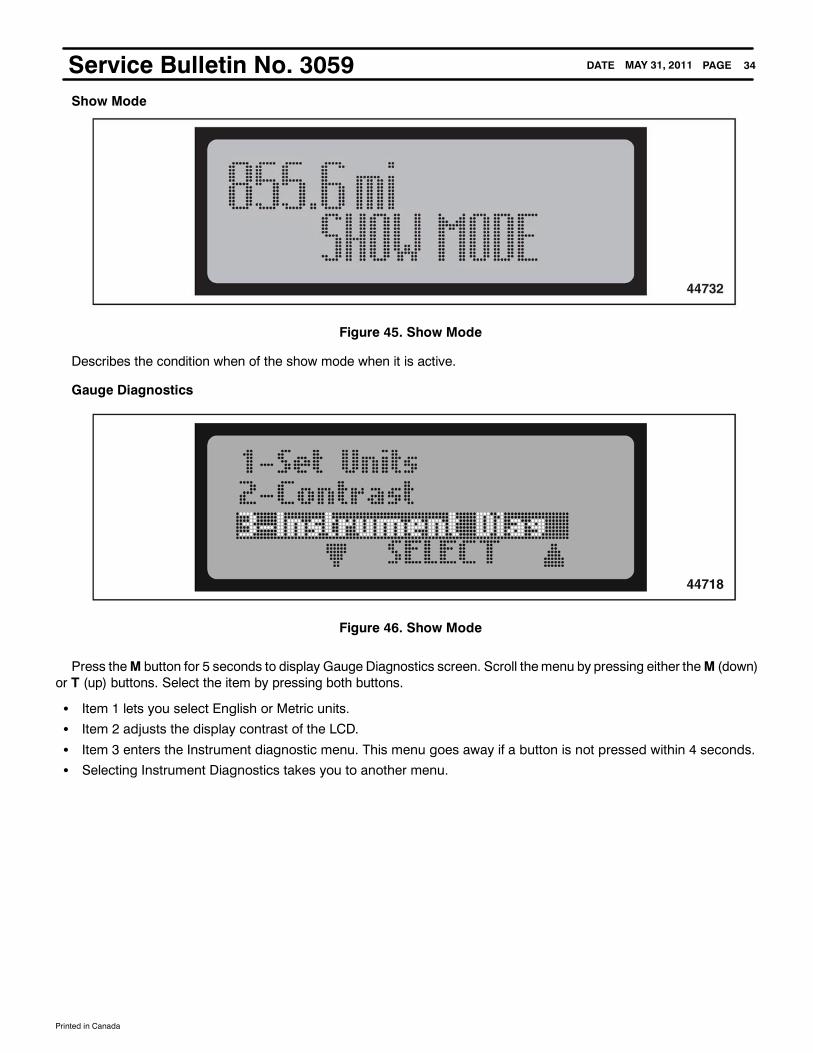
PAGEDATE 34MAY 31, 2011Service Bulletin No. 3059Show Mode
Figure 45. Show Mode
Describes the condition when of the show mode when it is active.
Gauge Diagnostics
Figure 46. Show Mode
Press theM button for 5 seconds to display Gauge Diagnostics screen. Scroll themenu by pressing either theM (down)or T (up) buttons. Select the item by pressing both buttons.
S Item 1 lets you select English or Metric units.S Item 2 adjusts the display contrast of the LCD.S Item 3 enters the Instrument diagnostic menu. This menu goes away if a button is not pressed within 4 seconds.S Selecting Instrument Diagnostics takes you to another menu.

Printed in Canada
PAGEDATE 35MAY 31, 2011Service Bulletin No. 3059
Figure 47. Show Mode
The instrument diagnostics menu has 4 items:
S Gauge TestS Lamp TestS LCD TestS Input StatusAgain, you can scroll the highlight bar by using the M and T buttons; then press both to select.

Printed in Canada
PAGEDATE 36MAY 31, 2011Service Bulletin No. 3059
Figure 48. Input Status Screen
All of the analog and binary inputs for the master (speedometer) are displayed. The display shows the connector pinnumber, analog or binary number, and the status.
S M---1 is Master gauge pin 1S AN IN 1 is analog input #1S 700.0 is the resistance value of the inputS M---11 is Master gauge pin 11S BIN IN 7 is binary input channel 7S High means the input is logic high (>4V)S WL---3 is Warning bank Left side pin 3S BIN IN 3 is binary input channel 3S High means the input is logic high (>4V).

Printed in Canada
PAGEDATE 37MAY 31, 2011Service Bulletin No. 3059Starter Diagnostics
Figure 49. Starter Diagnostics
ThePMMapplication andMessage center combine to provide systemdiagnostics for the starter.When the start switch ispressed the PMMsenses if the starter output has been energized. If not, the PMMdetermines what input is not correct anddisplays a message on the message center.
Starter Diagnostic Messages programmed into the speedometer include:
S STARTER FAULT --- there is an output fault in the PMMS FRONT MODE SW --- the Front/Rear switch is set to REARS REAR RUN SW --- the Rear Run switch is set to REARS TURN ON IGN --- the DMS is in the OFF or ACC positionS SELECT NEUTRAL --- the neutral signal is not detectedS ENGINE RUNNING --- engine RPM is detected > 400 (engine already running)S WAIT TO START --- the engine is not ready to attempt starting.

Printed in Canada
PAGEDATE 38MAY 31, 2011Service Bulletin No. 30594 in 1 Gauge
Figure 50. 4 in 1 Gauge
The 117mm 4-in--1 gauge has the following displays:
S Oil PressureS Water (Engine Coolant) TemperatureS Front (Primary) Air Brake PressureS Rear (Secondary) Air Brake Pressure
Figure 51. Backside -- 4 in 1 Gauge
Backside of gauge showing LIN/Power connectors. Both four pin connectors are identical; only 3 pins are used in each. Itdoes not matter which connector the LIN harness is connected to.
Printed in Canada
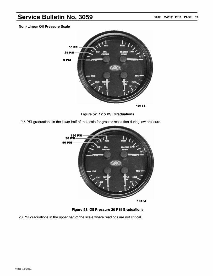
PAGEDATE 39MAY 31, 2011Service Bulletin No. 3059Non--Linear Oil Pressure Scale
Figure 52. 12.5 PSI Graduations
12.5 PSI graduations in the lower half of the scale for greater resolution during low pressure.
Figure 53. Oil Pressure 20 PSI Graduations
20 PSI graduations in the upper half of the scale where readings are not critical.
Printed in Canada
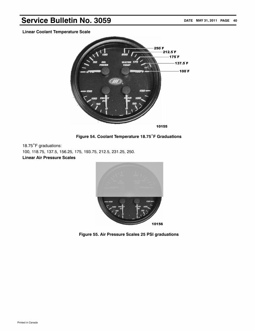
PAGEDATE 40MAY 31, 2011Service Bulletin No. 3059Linear Coolant Temperature Scale
Figure 54. Coolant Temperature 18.75˚F Graduations
18.75˚F graduations:100, 118.75, 137.5, 156.25, 175, 193.75, 212.5, 231.25, 250.Linear Air Pressure Scales
Figure 55. Air Pressure Scales 25 PSI graduations

Printed in Canada
PAGEDATE 41MAY 31, 2011Service Bulletin No. 3059MUX Right Hand Telltale
Common Features of New Dash Telltales:
S Multiplexed telltales, via LINS Two air pressure transducer Inputs (RH only)S Warning Bank module with 8 binary inputsS LED board with 30 warning LEDs availableS Foam divider to eliminate light bleed between iconsS Overlay with all warning icons screened on itS Icon color provided by LEDS Integrates pressure transducer quick disconnect
Figure 56. MUX RH Telltale (Backside)
Item Description
1 DOT Air Fittings --- LH air input is RED --- RH air input is GREEN (As viewed from backside of telltale)
Printed in Canada
PAGEDATE 42MAY 31, 2011Service Bulletin No. 3059
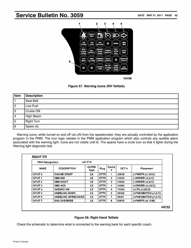
Figure 57. Warning Icons (RH Telltale)
Item Description
1 Seat Belt
2 Low Fuel
3 Cruise ON
4 High Beam
5 Right Turn
6 Spare (4)
Warning icons, while turned on and off via LIN from the speedometer, they are actually controlled by the applicationprogram in the PMM. The icon logic resides in the PMM application program which also controls any audible alarmassociated with the warning light. Icons are not visible until lit. The spares have a circle icon so that it lights during theWarning light diagnostic test.
Figure 58. Right Hand Telltale
Check the schematic to determine what is connected to the warning bank for each specific coach.

Printed in Canada
PAGEDATE 43MAY 31, 2011Service Bulletin No. 3059MUX Left Hand Telltale
Figure 59. MUX LH Telltale (Backside)
There are no serviceable parts on the telltale modules, they are replaced as a unit if there is a module failure.
Figure 60. Warning Icons (LH Telltale)
Item Description Item Description
1 Left Turn 8 Low Coolant Level
2 High Exhaust Temperature 9 Alternator Fail
3 Pre-Heat 10 Spare
4 Low DEF (Diesel Exhaust Fluid) Level 11 Stop Transmission
5 Check Engine 12 Check Transmission
6 Stop Engine 13 Check Brakes
7 MIL (Malfunction Indicator Lamp) 14 DPF (Diesel Particulate Filter)

Printed in Canada
PAGEDATE 44MAY 31, 2011Service Bulletin No. 3059
Figure 61. Left Hand Telltale
NOTE: Items shown in Description column are for D4500 coach.

Printed in Canada
PAGEDATE 45MAY 31, 2011Service Bulletin No. 3059Glossary
ABS Antilock Brake System
AMPS Actia Multiplexed Power Software
AN Analog
ATC Automatic Traction Control
BAT Battery
BIN IN Binary Input (Speedometer display). Example: BIN IN 7 refers to Binary Input channel 7.
BK Black (wire color)
BL Blue (wire color)
BR Brown (wire color)
BUS Common electrical connection between multiple electrical devices
CAN Controller Area Network
COMM Communication
DEF Diesel Exhaust Fluid
DM1 Active diagnostic trouble codes
DM2 Previously active diagnostic trouble codes
DM3 Diagnostic data clear/reset of previously active DTCs
DM11 Diagnostic data clear/reset of active DTCs
DPF Diesel Particulate Filter
DRC Deutsch Rectangular Connector
DTC Diagnostic Trouble Code
DVEC Dual Vehicle Electrical Center
ECU Electronic Control Unit
ENG Engine
GND Ground
HS High Side switch ; Same as a switch to battery output
IN Input
I/O Input/Output
LCD Liquid Crystal Display
LED Light Emitting Diode
LIN Local Interconnect Network
LS Low Side switch ; Same as a switch to ground output
LT Loadshed Over Temp (error code)
LV Loadshed Under Voltage (error code)
M Master, (Speedometer display). Example: M-1 refers to Master gauge, pin 1.
MIL Malfunction Indicator Lamp
Printed in Canada
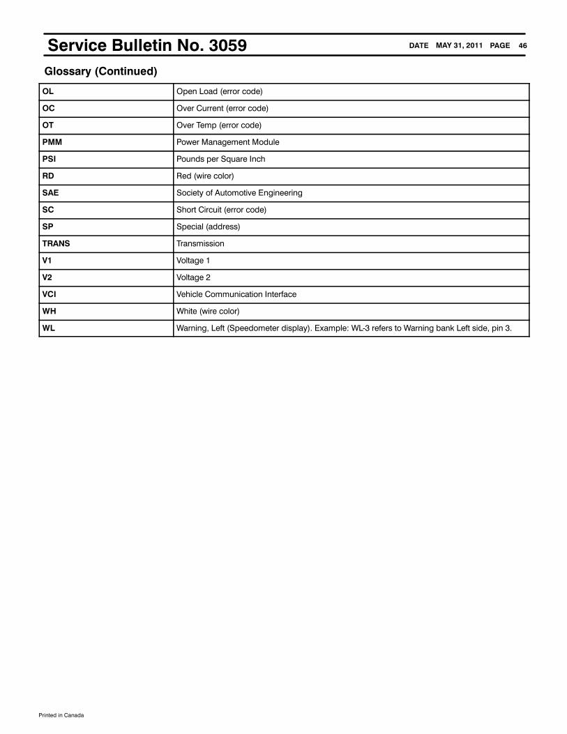
PAGEDATE 46MAY 31, 2011Service Bulletin No. 3059Glossary (Continued)
OL Open Load (error code)
OC Over Current (error code)
OT Over Temp (error code)
PMM Power Management Module
PSI Pounds per Square Inch
RD Red (wire color)
SAE Society of Automotive Engineering
SC Short Circuit (error code)
SP Special (address)
TRANS Transmission
V1 Voltage 1
V2 Voltage 2
VCI Vehicle Communication Interface
WH White (wire color)
WL Warning, Left (Speedometer display). Example: WL-3 refers to Warning bank Left side, pin 3.

Printed in Canada
PAGEDATE 47MAY 31, 2011Service Bulletin No. 3059
Diagnostics
Actia Multiplex System Troubleshooting Overview
Truth Tables are used to analyze the application logic and take the place of ladder logic diagrams. They are simple tounderstand and give the same information as a ladder logic diagram. The LCD Diagnostic Display gives the technician asingle location to view inputs andoutputs throughout theentire coach. Rowsare color-coded to help convey the significanceof each row in the logic block. The following example of the variable HighRise will help explain how to read and understandTruth Tables.
Figure 62. Variable Column
Item Description
1 Light Blue --- Application Module Name
2 Purple --- Communication Message
3 White --- PMM Input or Other
4 Orange --- Hardware Output
5 Yellow --- Flag/Internal Variable
6 Green --- Application Function
The first column (Variable) is the name of the function and the variable name associated with the logic.
Printed in Canada
PAGEDATE 48MAY 31, 2011Service Bulletin No. 3059
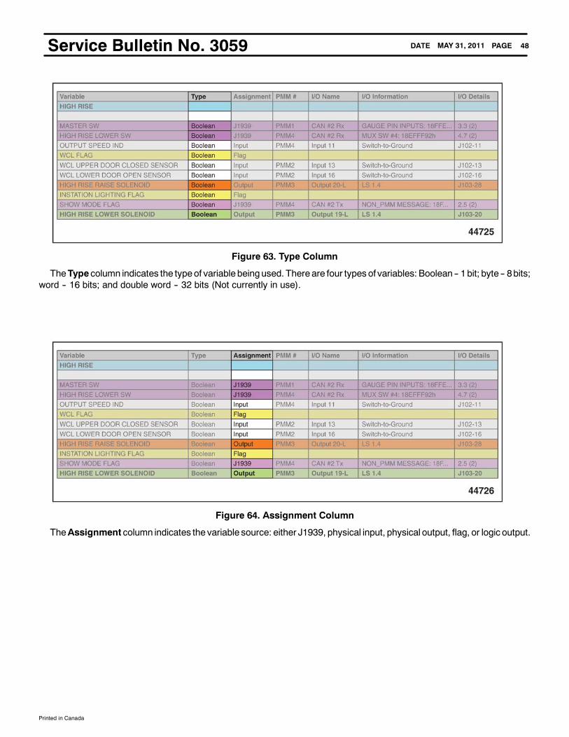
Figure 63. Type Column
TheType column indicates the typeof variable beingused. There are four types of variables: Boolean -- 1bit; byte -- 8bits;word -- 16 bits; and double word -- 32 bits (Not currently in use).
Figure 64. Assignment Column
TheAssignment column indicates the variable source: either J1939, physical input, physical output, flag, or logic output.

Printed in Canada
PAGEDATE 49MAY 31, 2011Service Bulletin No. 3059
Figure 65. PMM Number Column
The PMM # column indicates the PMM number that is supplying the variable.
Figure 66. I/O Name Column
The I/O Name column indicates the physical location on the PMM that is supplying the variable.

Printed in Canada
PAGEDATE 50MAY 31, 2011Service Bulletin No. 3059
Figure 67. I/O Information Column
The I/O Information column gives additional detail about the variable.
Figure 68. I/O Details Column
The I/ODetails column gives additional detail about the input variable such asByte/Bit, connector, and pin number of thevariable.
Printed in Canada
PAGEDATE 51MAY 31, 2011Service Bulletin No. 3059
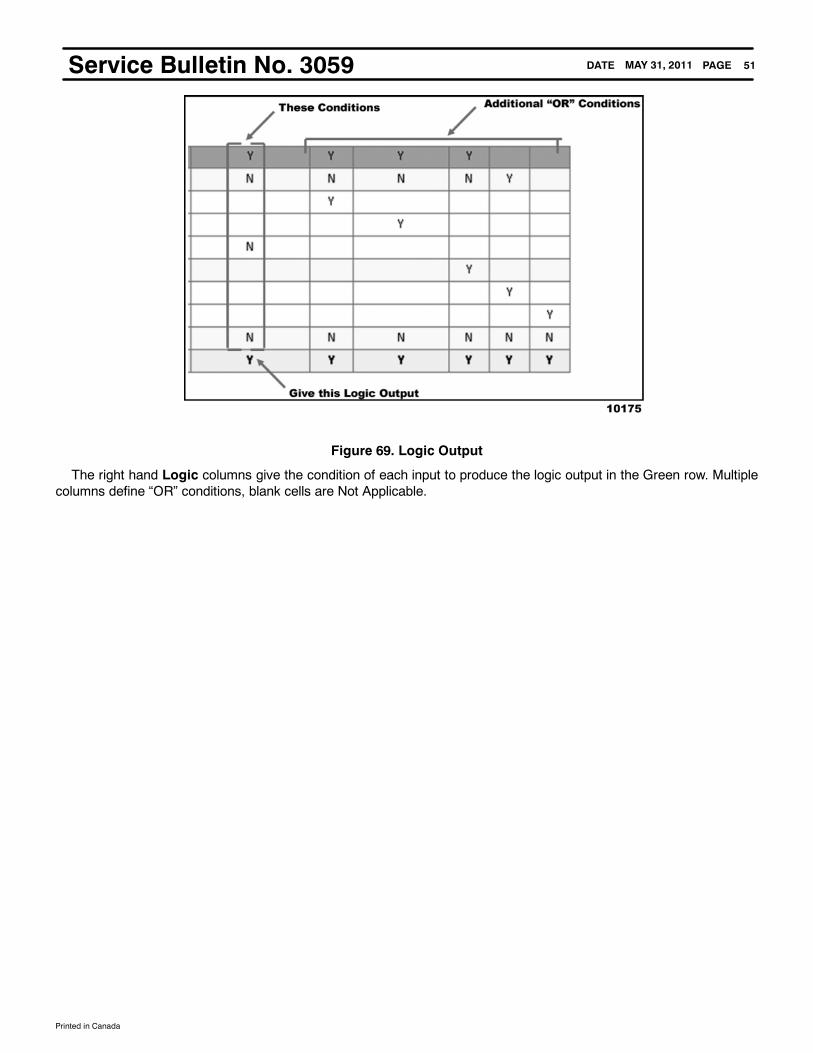
Figure 69. Logic Output
The right hand Logic columns give the condition of each input to produce the logic output in the Green row. Multiplecolumns define “OR” conditions, blank cells are Not Applicable.