Embed Size (px)
Citation preview

Northrop Grumman Cutting Edge Optronics Technical Note #17
kW‐Class, Wavelength‐
Stabilized Laser Diode Arrays
Numerous laser media exist with absorption peaks that are too narrow to make use of standard laser diode pump arrays with emission widths of 2-3 nm. For these absorption peaks (such as Nd:YAG at 885nm, Nd:YVO4 at 880nm, and Yb:YAG at 969nm), laser diode pump arrays with narrower emission spectra are highly beneficial. Northrop Grumman Cutting Edge Optronics has developed a process for building high-power laser diode arrays with narrow emission spectra by adding Volume Bragg Gratings during the packaging process. These arrays emit with a spectral width of approximately 0.5nm (FWHM), and are available with output powers ranging from tens of watts to several kilowatts. Experimental data is presented in this technical note for arrays operating at up to 100W per bar (CW). © 2011 Northrop Grumman Systems Corporation – All Rights Reserved
0
50
100
150
200
250
300
880 882 884 886 888 890
Intensity (arb. U
nits)
Wavelength (nm)
After VBG
Before VBG
Wavelength-Stabilized, High-Power Laser Diode Arrays
Ryan Feeler1, Joseph Levy, and Jeremy Junghans
Northrop Grumman Cutting Edge Optronics, 20 Point West Blvd., St. Charles, MO USA 63301
1. INTRODUCTION
A variety of applications exist for laser diode arrays with narrow wavelength spectra. The width of the wavelength spectrum of a typical high-powered laser diode bar is on the order of 1-2nm (FWHM), depending on the bar design and the operating parameters. When a significant number of laser diode bars are joined together to form an array, the differences in center wavelength of the individual bars combine with the typical intrinsic spread of each bar to produce arrays with wavelength spread of 2-3nm. While this is sufficient for a number of applications (pumping of some solid-state laser crystals, materials processing, etc.), it is completely insufficient for others.
The use of external wavelength locking elements has become a popular approach for producing laser diode arrays with narrow wavelength spectra (< 1 nm). This technology utilizes Volume Bragg Gratings (VBGs) as a means of providing feedback to the laser diode bar. This idea has been used extensively in the telecommunications industry for many years. It has also been used within the laser industry as a way to efficiently pump crystals or vapors that cannot be pumped by a diode array with a 2-3nm spectral width.
2. POTENTIAL USES
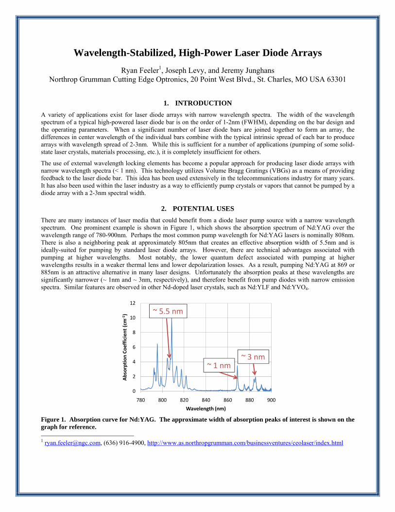
There are many instances of laser media that could benefit from a diode laser pump source with a narrow wavelength spectrum. One prominent example is shown in Figure 1, which shows the absorption spectrum of Nd:YAG over the wavelength range of 780-900nm. Perhaps the most common pump wavelength for Nd:YAG lasers is nominally 808nm. There is also a neighboring peak at approximately 805nm that creates an effective absorption width of 5.5nm and is ideally-suited for pumping by standard laser diode arrays. However, there are technical advantages associated with pumping at higher wavelengths. Most notably, the lower quantum defect associated with pumping at higher wavelengths results in a weaker thermal lens and lower depolarization losses. As a result, pumping Nd:YAG at 869 or 885nm is an attractive alternative in many laser designs. Unfortunately the absorption peaks at these wavelengths are significantly narrower (~ 1nm and ~ 3nm, respectively), and therefore benefit from pump diodes with narrow emission spectra. Similar features are observed in other Nd-doped laser crystals, such as Nd:YLF and Nd:YVO4.
Figure 1. Absorption curve for Nd:YAG. The approximate width of absorption peaks of interest is shown on the graph for reference. 1 [email protected], (636) 916-4900, http://www.as.northropgrumman.com/businessventures/ceolaser/index.html
0
2
4
6
8
10
12
780 800 820 840 860 880 900
Absorption Coefficien
t (cm
‐1)
Wavelength (nm)
~ 5.5 nm
~ 1 nm~ 3 nm

Another common laser crystal that benefits from pump arrays with narrow emission spectra is Yb:YAG. The absorption curve of Yb:YAG is shown in Figure 2. There is a broad absorption peak centered around 940nm and a narrow peak located at 969nm. As is the case with Nd:YAG, certain laser designs benefit significantly from pumping at the higher absorption peak. In this case it is again advantageous to pump with a narrow linewidth diode array.
Figure 2. Absorption curve of Yb:YAG. The approximate width of absorption peaks of interest are shown on the graph for reference.
3. TECHNICAL APPROACH
Northrop Grumman Cutting Edge Optronics (NGCEO) manufactures laser diode arrays in a wide variety of configurations with power levels ranging from 10 watts to a few kilowatts. NGCEO has developed a process for producing high-power laser diode arrays with emission spectra on the order of 0.5 nm by adding VBGs during the packaging process. NGCEO has included VBGs on some of its largest arrays, and has demonstrated these results in a production environment on arrays producing in excess of 3kW of continuous output power. These arrays feature microchannel-cooled packaging technology that allows high-powered laser diode bars (nominally 100W/bar) to be packaged in vertical stacks with bar-to-bar spacing (or pitch) of approximately 1.8 mm.
A basic schematic for this approach is shown in Figure 3. First, a high-power laser diode bar is soldered to a microchannel-cooled heatsink. This assembly is pre-tested to validate proper operation and inspected to ensure proper bond and facet quality. A number of these assemblies (from n=1 to 56, depending on customer specifications) are then stacked into an array. Fast-axis collimating (FAC) lenses are then attached to each heatsink using an active alignment process. Lastly, a small VBG is individually aligned to each bar/lens assembly and attached to the frame of the array.
Figure 3. Overview of approach used at NGCEO to produce wavelength-stabilized arrays. Not to scale. When the device is operated, the light emitted from the laser diode bar is collimated by the lens and impinges upon the grating. The grating preferentially reflects light of a pre-selected wavelength back through the lens and into the optical
0
2
4
6
8
10
12
14
850 875 900 925 950 975 1000 1025 1050
Ab
sorp
tio
n c
oef
fici
ent
(cm
-1)
Wavelength (nm)
~ 16 nm
~ 4 nm
Diode Bar
HeatsinkFAC LensVBG

cavity of the laser diode bar. This feedback method allows for light of a specific wavelength to be produced under a variety of operating parameters (temperature, current, etc.). NGCEO can produce wavelength-stabilized arrays in vertical stacks with up to 56 bars, or in horizontal or two-dimensional arrays of various sizes as determined by customer requirements. An example high-powered array is shown in Figure 4. This array is comprised of two 36-bar vertical stacks with a bar pitch of 1.8mm. The output of the stacks is combined with an interleaving mirror, resulting in a near doubling of the intensity.
Figure 4. Laser diode array featuring two 36-bar microchannel-cooled stacks, with output combined by an interleaving mirror.
4. EXPERIMENTAL DATA
NGCEO has built a number of multi-bar arrays with VBG elements for the purpose of narrowing the wavelength spectrum of the array. Data from a representative 36-bar stack is presented in this application note as a demonstration of product capabilities. This is an example of using narrow wavelength diode arrays to efficiently pump the 885nm absorption band of Nd:YAG, as shown in Figure 1. The output spectrum of a 36-bar laser diode array before and after the addition of wavelength-locking VBGs is shown in Figure 5. This data was collected at a CW drive current of 100A and has been normalized to the total output power of the array. The addition of VBGs to this array decreased the width of the wavelength distribution from 2.7 nm to 0.7 nm (FWHM).

Figure 5. Wavelength spectrum of a 36-bar microchannel cooled stack before and after the addition of VBGs. The data has been scaled to the total output power of the array. One of the primary benefits of utilizing VBGs is the ability to operate laser diode arrays over a variety of input parameters with little impact on the output wavelength. While VBGs are commonly used to ensure consistent wavelength over a range of operating temperatures, this is not an issue for the example arrays since they feature microchannel cooling and can be held to a very precise operating temperature. What is of interest, however, is the change in output wavelength as a function of drive current. This information is presented in Figure 6.
0
50
100
150
200
250
300
880 882 884 886 888 890
Intensity (arb. U
nits)
Wavelength (nm)
After VBG
Before VBG
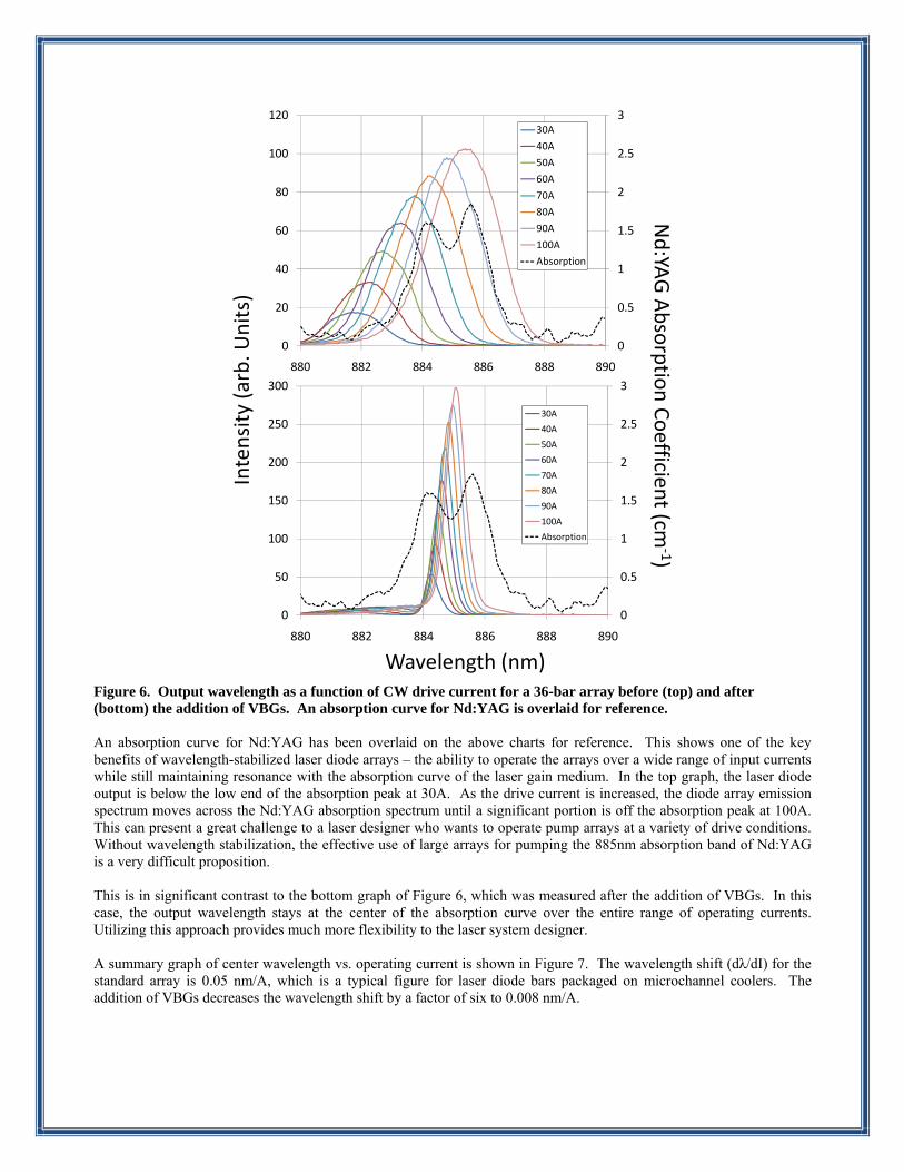
Figure 6. Output wavelength as a function of CW drive current for a 36-bar array before (top) and after (bottom) the addition of VBGs. An absorption curve for Nd:YAG is overlaid for reference. An absorption curve for Nd:YAG has been overlaid on the above charts for reference. This shows one of the key benefits of wavelength-stabilized laser diode arrays – the ability to operate the arrays over a wide range of input currents while still maintaining resonance with the absorption curve of the laser gain medium. In the top graph, the laser diode output is below the low end of the absorption peak at 30A. As the drive current is increased, the diode array emission spectrum moves across the Nd:YAG absorption spectrum until a significant portion is off the absorption peak at 100A. This can present a great challenge to a laser designer who wants to operate pump arrays at a variety of drive conditions. Without wavelength stabilization, the effective use of large arrays for pumping the 885nm absorption band of Nd:YAG is a very difficult proposition. This is in significant contrast to the bottom graph of Figure 6, which was measured after the addition of VBGs. In this case, the output wavelength stays at the center of the absorption curve over the entire range of operating currents. Utilizing this approach provides much more flexibility to the laser system designer. A summary graph of center wavelength vs. operating current is shown in Figure 7. The wavelength shift (dλ/dI) for the standard array is 0.05 nm/A, which is a typical figure for laser diode bars packaged on microchannel coolers. The addition of VBGs decreases the wavelength shift by a factor of six to 0.008 nm/A.
Wavelength (nm)
Nd:YA
GAbsorptio
n Coefficien
t (cm‐1)
Intensity (arb. U
nits)
0
0.5
1
1.5
2
2.5
3
0
20
40
60
80
100
120
880 882 884 886 888 890
30A
40A
50A
60A
70A
80A
90A
100A
Absorption
0
0.5
1
1.5
2
2.5
3
0
50
100
150
200
250
300
880 882 884 886 888 890
30A
40A
50A
60A
70A
80A
90A
100A
Absorption
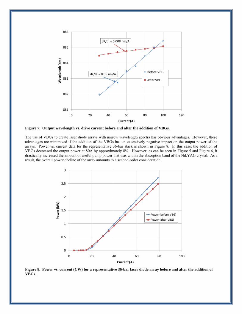
Figure 7. Output wavelength vs. drive current before and after the addition of VBGs.
The use of VBGs to create laser diode arrays with narrow wavelength spectra has obvious advantages. However, these advantages are minimized if the addition of the VBGs has an excessively negative impact on the output power of the arrays. Power vs. current data for the representative 36-bar stack is shown in Figure 8. In this case, the addition of VBGs decreased the output power at 80A by approximately 8%. However, as can be seen in Figure 5 and Figure 6, it drastically increased the amount of useful pump power that was within the absorption band of the Nd:YAG crystal. As a result, the overall power decline of the array amounts to a second-order consideration.
Figure 8. Power vs. current (CW) for a representative 36-bar laser diode array before and after the addition of VBGs.
881
882
883
884
885
886
0 20 40 60 80 100 120
Wavelength (nm)
Current (A)
Before VBG
After VBG
dλ/dI = 0.008 nm/A
dλ/dI = 0.05 nm/A
0
0.5
1
1.5
2
2.5
3
0 20 40 60 80 100
Power (kW)
Current (A)
Power (before VBG)
Power (after VBG)

5. CONCLUSION
Northrop Grumman Cutting Edge Optronics has developed a process for reliably attaching Volume Bragg Gratings to high-power laser diode arrays as a means of producing arrays with narrow wavelength spectra. This approach has a variety of applications, including pumping laser gain media that cannot be otherwise pumped with laser diode arrays. The data presented in this technical note shows a narrowing of the wavelength spectrum by a factor of 4. In addition, the change in output wavelength as a function of drive current has been decreased by a factor of 6. The overall output power of the arrays suffers an overall power penalty of approximately 8%, but this is overcome by the ability to produce significantly more output power that is in the absorption band of the laser gain medium.

Our Products
Laser Diode Arrays CEO® offers a full line of conductively cooled, water cooled or microchannel cooled laser diodes and stacks. Choose from our wide range of standard product offerings including Golden Bullet arrays for long pulse (>500 µs) applications. Wavelengths from 780 – 1550 nm are available. CW Pumped Laser Modules Our range of diode modules are an ideal 'pump engine' solution for OEM manufacturers of Diode Pumped Solid State (DPSS) lasers. They are available with a variety of gain media options (Nd:YAG, Nd:YLF, Nd:YVO4 etc.). Output powers ranging from 20 W (TEMoo) to 800 W (multi mode) are available. QCW Pumped Laser Modules For high energy pulsed laser applications, CEO offers the PowerPULSE family of modules to deliver output energies up to 4 J per pulse and small signal gain in excess of 600. CTE matched, 'hard solder' laser diode packaging technology ensures long operating lifetimes. Electronics & Support Equipment Choose from CEO’s complete line of proven and versatile OEM high powered diode drivers and laser system controllers along with all the support equipment needed to operate high power CW and QCW pump modules or other diode-based laser systems. Industrial Laser Systems CEO offers industrial laser systems for micro-machining, marking, cutting, drilling, welding, soldering, and other industrial uses. These lasers utilize long-life diode pump sources to enable long laser lifetimes. Custom lasers can be built to a wide range of specifications. Military & Custom Lasers CEO® offers complete custom laser design engineering and manufacturing services of diode pumped solid state lasers (DPSS), laser diode arrays and modules for military, aerospace and industrial OEM laser applications. CEO specializes in engineering systems that are required to operate in harsh rugged environments including military & civilian helicopters, fixed wing aircraft, ground vehicles, and submerged towed bodies.
Contact Us Telephone: 636.916.4900
Fax: 636.916.4994 [email protected]
20 Point West Boulevard, St. Charles, MO (USA), 63301 http://www.as.northropgrumman.com/businessventures/ceolaser/index.html