Embed Size (px)
Citation preview
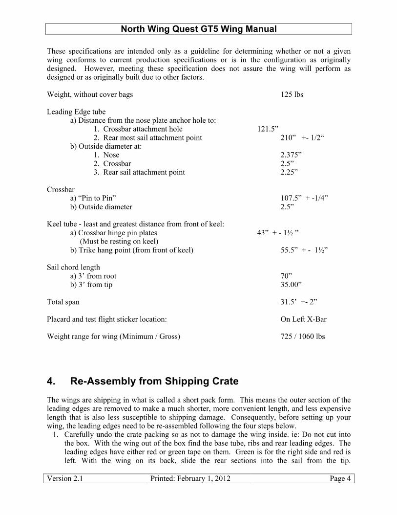
North Wing Quest GT5 Wing Manual
Version 2.1 Printed: February 1, 2012 Page 1
Manufacturer: North Wing UUM, Inc. 3904 Airport Way East Wenatchee, WA 98802 USA Phone : + 509-886-4605 Fax : + 509-886-3435 Website: [email protected]

North Wing Quest GT5 Wing Manual
Version 2.1 Printed: February 1, 2012 Page 2
Table of Contents 1.! About This Manual ................................................................................................................. 3!2.! About the Quest GT5 Trike Wing ......................................................................................... 3!3.! Technical Specifications/ Compliance Verification Sheet ..................................................... 3!4.! Re-Assembly from Shipping Crate......................................................................................... 4!5.! Setup Procedure ...................................................................................................................... 6!
5.1! Attaching Your Wing to a Trike ................................................................................... 13!6.! Fold Down Procedure ........................................................................................................... 15!7.! About Flying the Quest GT5 Wing....................................................................................... 16!
7.1! General Flying Practices ............................................................................................... 16!7.2! Flying Speeds................................................................................................................ 17!
7.2.1! Selected Flying Speed Definitions............................................................................ 17!7.2.2! Typical Speeds .......................................................................................................... 17!
7.3! Adjusting Vc: Center of Gravity (CG) Adjustment ...................................................... 17!8.! Inspections ............................................................................................................................ 18!
8.1! Preflight Inspection Checklist....................................................................................... 19!8.2! Annual and 100-Hour Inspections ................................................................................ 20!8.3! Extended Period Inspection .......................................................................................... 22!
9.! Wing Maintenance: Quest GT5 wing ................................................................................... 23!9.1! Wing Cleaning .............................................................................................................. 23!9.2! Sail Tears Less than 1” Long........................................................................................ 23!9.3! Sail Tears Greater Than 1” Long.................................................................................. 24!9.4! Wing Tuning ................................................................................................................. 24!9.5! Sail Removal from Frame: Quest series ....................................................................... 32!9.6! Replacing Sail on Frame............................................................................................... 36!9.7! Leading Edge Replacement .......................................................................................... 39!9.8! Keel Tube Replacement................................................................................................ 44!9.9! Crossbar Replacement .................................................................................................. 45!9.10! Front and Rear Pitch Cables (Lower Rigging) Replacement ....................................... 46!9.11! Owner Replaceable Wing Fittings and Hardware ........................................................ 48!9.12! Non-Owner Replaceable Wing Fittings and Hardware ................................................ 49!
10.! Transportation and Storage................................................................................................... 50!11.! Wing Retirement................................................................................................................... 50!12.! Limitation of Liability .......................................................................................................... 51!13.! Owner’s Maintenance Log.................................................................................................... 51!Appendix A: Preflight Inspection Checklist ................................................................................. 52!

North Wing Quest GT5 Wing Manual
Version 2.1 Printed: February 1, 2012 Page 3
1. About This Manual Most everything the pilot needs to know about the Quest GT5 Wing from North Wing is contained within this manual. It is recommended that you thoroughly familiarize yourself with the entire manual before you fly your new wing for the first time. It is very important that you become familiar with the set-up procedure for the Quest GT5, or it is possible to damage it. Please take the time to look through the appropriate set-up sections before attempting assembly. Having an experienced dealer show you how to set your new wing up is also a good way go. Most importantly, you are reminded that this manual is not intended as an instructional device on how to fly weight shift trikes. Rather, as the purchaser of this product, in the spirit of our self-regulated sport, you are responsible for bringing with you the expertise required to safely operate this vehicle. If your trike is a Light Sport aircraft you need the proper Light Sport documentation to fly your Trike legally. By purchasing or operating this product, you assume complete liability for its safe operation. North Wing offers this owner’s manual simply to assist you with the features particular to this model of trike wing regarding it’s unique: assembly, flying characteristics, care and maintenance, and technical specifications. For those looking to advance or refine their particular flying skills, consult the fine line of instructional books dedicated to ultralight skill-building written by Dennis Pagen, or the factory can recommend any number of professional flight training centers. Please practice safe aviation! 2. About the Quest GT5 Trike Wing The Quest GT5 is a intermediate to advanced trike wing. You should have a minimum of 30 hrs of flight experience in weight shift trikes with an instructor’s approval before flying a Quest GT5. Congratulations on the purchase of your new North Wing Quest GT5. We believe it to be the finest available high performance recreational trike (flex) wing in the market today. The Quest GT5 achieves exceptional low speed performance and superb handling for many reasons. Its sail body and cut are composed of a carefully selected and applied field-proven synthesis of the latest materials that is matched to the leading edge curve. The sail body features a leading edge pocket internally reinforced with a mylar sheet insert. Drag is reduced with a faired side struts. These features combine to ensure a good usable flight performance. 3. Technical Specifications/ Compliance Verification Sheet
North Wing Quest GT5 Wing Manual
Version 2.1 Printed: February 1, 2012 Page 4
These specifications are intended only as a guideline for determining whether or not a given wing conforms to current production specifications or is in the configuration as originally designed. However, meeting these specification does not assure the wing will perform as designed or as originally built due to other factors. Weight, without cover bags 125 lbs Leading Edge tube a) Distance from the nose plate anchor hole to: 1. Crossbar attachment hole 121.5” 2. Rear most sail attachment point 210” +- 1/2“ b) Outside diameter at: 1. Nose 2.375” 2. Crossbar 2.5” 3. Rear sail attachment point 2.25” Crossbar a) “Pin to Pin” 107.5” + -1/4” b) Outside diameter 2.5” Keel tube - least and greatest distance from front of keel: a) Crossbar hinge pin plates 43” + - 1! ” (Must be resting on keel) b) Trike hang point (from front of keel) 55.5” + - 1!” Sail chord length a) 3’ from root 70” b) 3’ from tip 35.00” Total span 31.5’ +- 2” Placard and test flight sticker location: On Left X-Bar Weight range for wing (Minimum / Gross) 725 / 1060 lbs 4. Re-Assembly from Shipping Crate The wings are shipping in what is called a short pack form. This means the outer section of the leading edges are removed to make a much shorter, more convenient length, and less expensive length that is also less susceptible to shipping damage. Consequently, before setting up your wing, the leading edges need to be re-assembled following the four steps below.
1. Carefully undo the crate packing so as not to damage the wing inside. ie: Do not cut into the box. With the wing out of the box find the base tube, ribs and rear leading edges. The leading edges have either red or green tape on them. Green is for the right side and red is left. With the wing on its back, slide the rear sections into the sail from the tip.

North Wing Quest GT5 Wing Manual
Version 2.1 Printed: February 1, 2012 Page 5
REMEMBER, now that the wing is on its back, the left and right sides will be reversed as you look from the tips of the wing toward the nose. Be careful to guide the sprogs through the sail so they do not snag on the sail.
2. Turn the sprogs so they point towards the tip. Slide the rear section into the front section until the holes line up. Be sure the eye bolt is facing UP since the wing is on its back. Install bolt from the bottom up, wrap the mylar protector around the LE and put over the bolt, now thread the nut on over the mylar. Tighten snug (just to the point of no slack). Do not over tighten or you may oval the tube.
3. Now install the 3/8” eye bolt through the X-bar channel bracket and into the X-bar. The sequence of washers etc can be seen in the picture below: 1/4” thick black plastic spacer, mylar, bottom side of channel bracket, spacer tubing, top side of channel bracket, white nylon washer (between the bracket and X-bar), X-bar. On the inside of the X-bar you will have the half moon spacer, stainless steel fender washer, standard washer, then the castle nut and safety.

North Wing Quest GT5 Wing Manual
Version 2.1 Printed: February 1, 2012 Page 6
4. Install the tip sail strap (yellow) over the end of the trim tip cap. Make sure that the strap is in the 1” wide slot. See picture. Note: You can take the sail nose screws out of the grommet to make it easier to put the webbing over tip. After the webbing is over tip cap, at the nose run a string from grommet to grommet and around the nose plate and tighten line to pull tension on the leading edges. Now you are ready to set up your new wing. After the wing is completely set up and you have put in the nose ribs, you can reinstall the nose screws.
5. Setup Procedure The best value that this chapter can provide the owner is to share some techniques and procedures that other people using the Quest GT5 have discovered; things that will minimize wear or even prevent needless damage from occurring. Use this information to extend the life of your wing.

North Wing Quest GT5 Wing Manual
Version 2.1 Printed: February 1, 2012 Page 7
1. Assemble The Control Frame Place the wing on the ground with it’s nose pointing 120 degrees to the wind (if the wind is over 5 MPH) and with the zipper facing upward. Unzip the cover bag; remove the ribs from the nose area and the side struts. Undo the wing ties and assemble the control frame. Check the rigging to ensure that it is not tangled.
2. Roll The Wing Over Stand wing on the control frame (do not attach the lower front wires at this time).
3. Remove Bag and Spread Wings Ensure that the keel stand “stinger” is in place. Carefully walk each wing out to 3/4 of full open position. Leave enough slack in the sail so that during the next step the ribs may slide in with minimal resistance. Do not remove the wing tip bags at this point. They will protect the wing tips from ground damage/dirt until the wing it tensioned in a later step.

North Wing Quest GT5 Wing Manual
Version 2.1 Printed: February 1, 2012 Page 8
4. Insert Inboard Ribs Install all but the last three curved ribs; white ribs go to the right, black to the left. Insert the ribs from root to tip with gentle pressure, moving the sail’s trailing edge up or down as necessary to help the front of the ribs up over the crossbar and leading edge. Keep the rear tip close to the ground so the curved front glides smoothly in the pocket. DO NOT FORCE the ribs into place, especially the first two ribs (in particular when the sail is crispy new). To put the first ribs in, lift the keel off the ground about 20”. To open the flip tip on the end of each rib, be sure to squeeze the plastic tip with your fingers to release the catch. When closing the tip, you can simply pull it into position without squeezing the tip. Opening the tip without squeezing the catch will break the tip.

North Wing Quest GT5 Wing Manual
Version 2.1 Printed: February 1, 2012 Page 9
New style flip tips Flip and click closed
(insert into trailing edge)
5. Pre-Tension the Crossbar Walk the leading edge tubes out the rest of the way without forcing them. Find the crossbar tensioning nylon line at the center of the sail. Sometimes the loop of this line needs to be put back through the center hole in the sail. Also, check to be sure the nylon line is properly routed on the wheel of the small pulley on the cross bar junction plate. Sometimes it slips onto the side of the wheel pulley. Pull on the nylon line to pull back the cross bar. Pull back until the nylon rope loop can be hooked into the spring catch on top of the rear keel tube. This opens the wing spars enough to hook up the side struts. DO NOT FLY THE WING LIKE THIS! You must use the main restraint cable to fly.
6. Install Struts Place struts under wing on each side. There is a left and right strut and are marked. The strut also should be marked top. This is the side that has a 5/16” clevis pin. First hook up the lower end of the strut (1/4” pin) then the top. Make sure you install the safety rings and make sure that the safety rings are not sprung open even a small amount.

North Wing Quest GT5 Wing Manual
Version 2.1 Printed: February 1, 2012 Page 10
Old Corner Hardware (recommend replacing) New Corner Hardware
7. Hook Up Cross Bar Main Cable Remove the pull back nylon line from the spring catch. Pull the line all the way back until the main restraint cable shackle can be clipped into the spring catch. Make sure the wing tip yellow strap is in the slot in the tip cap before pulling the nylon line back.

North Wing Quest GT5 Wing Manual
Version 2.1 Printed: February 1, 2012 Page 11
8. Insert Remaining Ribs With the struts installed and the wing tensioned, the wing tips will be off the ground. Remove the tip bags and insert the remaining 3 tip ribs on each side. The straight end tip strut (rib) on each side does not have rib pockets. The open end of these ribs must be inserted onto the rib hooks that are riveted to the leading edge about 2 feet from the end of the leading edge. Then the flip tip on the trailing edge of the rib can be put in the pocket.

North Wing Quest GT5 Wing Manual
Version 2.1 Printed: February 1, 2012 Page 12
9. Locate Sprogs Into Position (If it is light winds you can put the wing on its nose for this) Open the zipper at each sprog location, rotate the four sprogs out to center of the transversal batten. Now put the Velcro loop around the end of the sprogs. Leave Velcro loops slightly loose (approximately 1/2” gap).
10. Install Under Surface Ribs Install the under surface ribs from longest to shortest. Make sure the back ends are inserted back into the slot at the rear.
11. Attach Front Flying Wires Ensure that all the lower rigging is untangled first. Position
the ring on the latch; install bolt, nut & safety pin.

North Wing Quest GT5 Wing Manual
Version 2.1 Printed: February 1, 2012 Page 13
12. Position The Nose Ribs And Nose Cone Pull the nose down to eye level so you can put the nose rib on the 1/4” stud located front top of keel tube. With nose cone in hand start with the two top Velcro tabs and gently pull the nose cone down and around the nose plate to connect the two bottom Velcro tabs on the nose cone to its corresponding Velcro sewn on the under surface below the keel.
Now make sure all zippers are closed after you per-flight your wing and before you fly. Cover bag, pads, and ties can fold into one of the bag ends for storage. Before you attach the wing to the trike be sure to perform a thorough preflight as described on the following pages.
5.1 Attaching Your Wing to a Trike North Wing provides two types of pivot block assemblies; a U-pivot block and a double plate block. Both are shown in the figures below. Either assembly can be used to attach your trike to the GT5 wing. The U-pivot block stays attached to the wing upon disassembly, while the double

North Wing Quest GT5 Wing Manual
Version 2.1 Printed: February 1, 2012 Page 14
plate assembly stays attached to the trike when disassembled. Both use split ring collars to adjust the position of the hang block on the keel tube, thereby adjusting the CG of the trike. Either assembly can be ordered from North Wing to attach a GT5 wing to another manufacturer’s trike such as an Airborne, Air Creation or Aero trike. U-Pivot Block: The black nylon bushing is a split sleeve that is slipped on the keel tube initially. Then the U-bracket is assembled in the sequence shown below. There are two holes for the trike attachment bolt. In general, the center hole is typically used unless there is some interference from the trike mast of another manufacturer’s trike. Then the off-center hole can be used. The second hole can also be used to adjust the CG of the trike if desired. The primary CG adjustment is the positioning of the split ring collars on either side of the pivot block.
Plate Pivot Block: The plate pivot block consists of a nylon bushing that is slipped over the keel tube and two side plates that are bolted together during assembly. Only the top bolt is removed to attach the wing to the trike. The other three bolts stay in place when disassembled and the plates remain on the trike mast.

North Wing Quest GT5 Wing Manual
Version 2.1 Printed: February 1, 2012 Page 15
6. Fold Down Procedure To fold down your Quest GT5, just reverse the set up procedure steps as described in Section 4. Included below are a few guidelines to follow which will save you time and prevent wear or damage when folding your wing.
• Tip bags: Remember to remove last 4 ribs, install the wing tip bags and un-zip access zippers for upper wing strut before releasing the crossbars cable.
• Folding wings in: Always fold the wings together symmetrically, bringing both leading
edges back together at the same time. If you don’t have someone helping you, then bring in one side about " of the way, then bring the other in about ! way, incrementally bringing in one side then the other in three to four incremental steps. CAUTION: If you meet resistance folding in the wings, check that the crossbar tensioning line or cable are free to run forward through the cable hole in the center of the sail. If the cable snags on the sail, it can easily tear the sail when you fold the wings in.
• Folding sail: The important thing here is to simply get your sail body neatly stowed
inside the Mylar reinforced leading edge pocket. Some owners prefer to alternate folding, then rolling, their sail to minimize potential permanent creases developing over time.
• Attaching sail ties: Fasten the first tie just aft of the rear cable (or X-bar latch. By
keeping the keel tube outside of the tie, it will make it easier to organize the control bar in this area after the wing is flipped over. The forward tie is located splitting the distance between the control frame apex and nose plate. Pull the leading edge pocket up over the top of the wing so the tops of the LE mylar pockets are touching and/or overlapped. The third sail tie goes about 2 feet inboard from the wing tips.

North Wing Quest GT5 Wing Manual
Version 2.1 Printed: February 1, 2012 Page 16
7. About Flying the Quest GT5 Wing
7.1 General Flying Practices Operations and limitation for the Quest GT5 wing on the Light Sport Scout X-C or the Sport X2 is available in the POH manual. The wing performance placard bearing test flight information and operating limits is located on the wing’s left crossbars. Special care should be taken to note the operating limitations, which are clearly stated on the flight operation placard. As with any wing, special care should be taken to note the operating limitations, which have been ascertained by careful testing. Flight operations should not exceed those laid down in the operating limits specified within this manual. No wing is totally safe; there are inherent risks involved in flying a trike wing. It is quite possible to fly the Quest GT5 beyond its operating limits using deliberate flying skills. Do not do this! The responsibility for safety rests ultimately with the pilot alone who must decide whether the wing they are about to fly has been properly maintained, and is in air worthy condition.
• FLIGHT OPERATIONS: Should be limited to non-aerobatics maneuvers -- those in which the pitch angle will not exceed either 30 degrees nose up or nose down of the horizon and in which the bank will not exceed 60 degrees.
• WARNING: The owner and operator must understand that, due to the inherent risk
involved in flying such a unique vehicle, no warranty is made or implied of any kind against accidents, bodily injury, or death. Operations such as aerobatics maneuvers or erratic pilot technique may ultimately produce equipment failure and are strongly discouraged.
• NEVER FLY FASTER THAN 90 MPH: To verify the speeds you are achieving, you
should fly with an accurate airspeed indicator. During certification testing, test pilots found that it would be possible to exceed Vne during smooth acceleration. The most typical cause of exceeding Vne is rapid acceleration performing aerobatics maneuvers and steep dives. This wing is not tested to perform such maneuvers, and they should not be attempted.

North Wing Quest GT5 Wing Manual
Version 2.1 Printed: February 1, 2012 Page 17
7.2 Flying Speeds There are a number of important flying speeds you should know for your Quest wing. Some of these speeds change depending upon which trike carriage you are using, where the center of gravity (CG) is set, weight being carried, and engine/propeller combination. Additional information about air speeds is provided in the POH for standard North Wing configurations. For this manual, typical numbers and their importance for some of the more critical speeds is given in the list below.
7.2.1 Selected Flying Speed Definitions VA - Maneuvering Speed – the indicated airspeed above which the pilot should not make full
or abrupt control movements VC - Design cruise speed based on CG setting (Trim speed) The indicated airspeed at which
the aircraft remains in a stabilized condition without pilot input (hands off). This changes depending up loading and CG positioning. Trim speed can be adjusted for desired speed and handling by moving the trike forward (speed up) or back (slow down) on the keel tube of the wing.
VNE - The indicated airspeed that the aircraft is never to exceed for structural reasons VS - Stall Speed – the indicated airspeed at which an uncontrolled downward pitching motion
of the aircraft occurs and sufficient lift to maintain level flight is no longer possible. Stall occurs when the wing reaches its critical angle of attack. However, that may occur at different speeds depending upon loading, attitude, power setting, etc.
7.2.2 Typical Speeds VA - 75 mph Do not make fast or full control movements at or above this speed! VC - 55-65 mph VNE - 85 mph Do not exceed this speed in any operation. The Quest GT5, even
when flown in its lightest wing loading, can exceed 85 mph. VS - 40 mph @ Gross weight VS - 37 mph @ 700 lbs At gross load the Quest GT5 may stall as high as 44mph depending on your trim setting, loading, and tuning.
7.3 Adjusting Vc: Center of Gravity (CG) Adjustment The Quest GT5 wing likes to fly between 55 to 65 MPH at hands off trim. This is where the trim is set during factory test flight. As mentioned above, the CG of the trike can be shifted forward and aft, thereby changing the cruise speed, VC. However, it is important to keep the CG within the range specified below to avoid undesirable flight characteristics and difficult handling.

North Wing Quest GT5 Wing Manual
Version 2.1 Printed: February 1, 2012 Page 18
The trike center of gravity (CG) is adjusted by moving the trike hang point forward or aft on the keel tube. The range is measured by the distance from the front edge of the front retaining collar to the front tip of the keel tube (not nose bracket). See the sketch below.
In its forward most position, the front collar is a distance of 54” from the front of the keel tube. The pivot block assembly may be moved rearward a maximum of 2.5” resulting in a measurement from the keel tube tip to the front collar of 56.5”. The hang point is changed by loosening the split collar bolts evenly about 3 turns each with a "” T-handle Allen wrench. This should be enough to slide the collars to the desired position. Note! It is helpful to have the wing nose pointing up when moving the hang point forward and the wing nose pointing down when moving the hang point rearward. This will allow the wing weight to help slide it in the pivot block assembly with little manual force. If the wing does not move easily with a little help, rock the base tube left and right (as if turning) a few inches while the nose is leaning in the desired direction until the wing settles against the new position of the retaining collar. Move the other retaining collar up against the pivot block and tighten. The total gap between the collars and the pivot block should be less than 1/8”. Tighten the collar bolts EVENLY. DO NOT tighten just one collar bolt completely and then the other. This will distort and possibly damage the keel tube. This can be checked by confirming that the gaps between the split-collar ends are equal. 8. Inspections

North Wing Quest GT5 Wing Manual
Version 2.1 Printed: February 1, 2012 Page 19
There are essentially four levels of inspection that may apply to your aircraft:
1. Pre-flight inspection 2. Annual inspection 3. 100-hour inspection 4. Extended period inspection
8.1 Preflight Inspection Checklist
A thorough preflight procedure is mandatory with all aircraft, and must be done prior to every flight…even if someone else just landed with the aircraft and reported no problems. This is your first line of defense against any unknown damage or degradation due to age, wear, or hostile environmental conditions such as weather, birds, mice, and sun exposure. The best technique is common-sense pattern. A detailed Pre-flight check list is given in Appendix A for convenient print out. Put a copy in your trike and use it before every flight. The FAA recognizes two acceptable approaches to use a pre-flight checklist. The pilot can read each item and check that point one at a time, or the pilot can follow the “common-sense” pattern, then refer to the check list to assure nothing was overlooked. There is some evidence that the latter results in a better pre-flight because it is not as prone to accidentally skipping an item in the list. The pre-flight checklist in Appendix A starts at the nose of the wing, then moves down the left side leading edge then back to the keel tube along the trailing edge. This sequence is then repeated on the right side. Then the checklist moves to the connections and critical points along the keel tube such as the haul back cable, nose cables, crossbar connections, and downtube connections. It finishes the wing pre-flight by stepping back and looking at the wing as a whole and checking the top of the wing for damage. After a few times through this pattern, you will be able to step through it smoothly and then refer back to the checklist to assure nothing has been overlooked.

North Wing Quest GT5 Wing Manual
Version 2.1 Printed: February 1, 2012 Page 20
8.2 Annual and 100-Hour Inspections The Annual Inspection or 100-Hour Inspection supplements the pre-flight inspection that should be done prior to each flight. That is, the Annual or 100-hour inspection addresses more depth and looks at possible wear or aging events that can occur over a longer period of time. Since this inspection may be done by another person other than the owner or pilot, the inspection list includes checks from the pre-flight list as well. If problems are identified by the inspection that should have been identified by the pilot during pre-flight checks, the pre-flight procedure should be modified to assure all points are being checked. All S-LSA and E-LSA aircraft must undergo an annual condition inspection. An S-LSA must be inspected by a qualified Repairman with at least a Maintenance rating (LSR-M). This requires satisfactory completion of an FAA approved 104-hour Repairman-Maintenance class for Weight Shift Control. In addition, anyone with an A&P certificate with Rotax Line Service Training may perform the inspections. An E-LSA aircraft can be inspected by someone with the above qualifications, or by the owner IF he has completed and passed a 16 hour inspection course, AND has received his Repairman Light Sport Aircraft certificate with an authorization for his specific aircraft from his local FSDO. For E-LSA and S-LSA aircraft used for non-commercial operation, an inspection is required every 12 months. For S-LSA aircraft used for commercial training or towing, an inspection is required every 100 hours of operating time in addition to the annual condition inspection. The checklist for these inspections is the same and is given below. This list incorporates all the applicable items required by FAR 43, Appendix D.
North Wing Quest GT5 Wing Manual
Version 2.1 Printed: February 1, 2012 Page 21
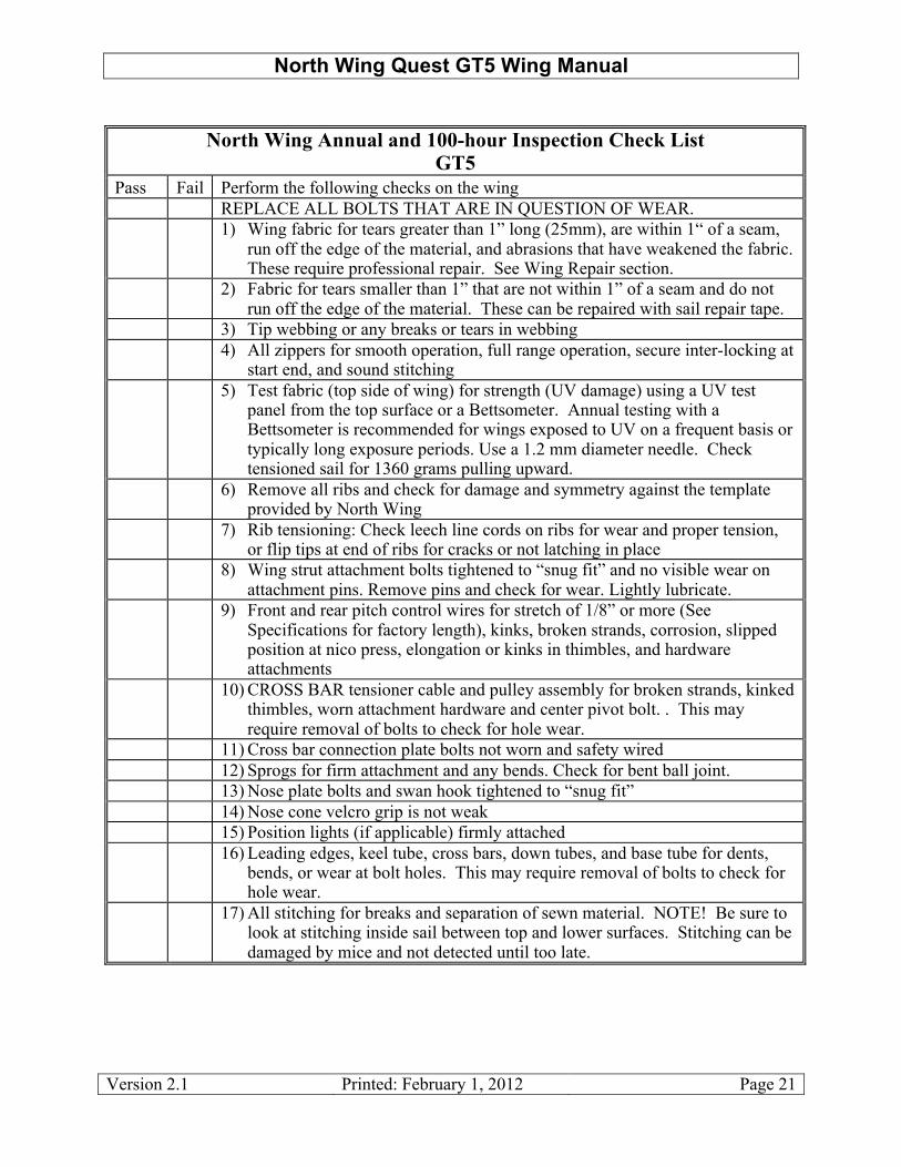
North Wing Annual and 100-hour Inspection Check List
GT5 Pass Fail Perform the following checks on the wing REPLACE ALL BOLTS THAT ARE IN QUESTION OF WEAR. 1) Wing fabric for tears greater than 1” long (25mm), are within 1“ of a seam,
run off the edge of the material, and abrasions that have weakened the fabric. These require professional repair. See Wing Repair section.
2) Fabric for tears smaller than 1” that are not within 1” of a seam and do not run off the edge of the material. These can be repaired with sail repair tape.
3) Tip webbing or any breaks or tears in webbing 4) All zippers for smooth operation, full range operation, secure inter-locking at
start end, and sound stitching 5) Test fabric (top side of wing) for strength (UV damage) using a UV test
panel from the top surface or a Bettsometer. Annual testing with a Bettsometer is recommended for wings exposed to UV on a frequent basis or typically long exposure periods. Use a 1.2 mm diameter needle. Check tensioned sail for 1360 grams pulling upward.
6) Remove all ribs and check for damage and symmetry against the template provided by North Wing
7) Rib tensioning: Check leech line cords on ribs for wear and proper tension, or flip tips at end of ribs for cracks or not latching in place
8) Wing strut attachment bolts tightened to “snug fit” and no visible wear on attachment pins. Remove pins and check for wear. Lightly lubricate.
9) Front and rear pitch control wires for stretch of 1/8” or more (See Specifications for factory length), kinks, broken strands, corrosion, slipped position at nico press, elongation or kinks in thimbles, and hardware attachments
10) CROSS BAR tensioner cable and pulley assembly for broken strands, kinked thimbles, worn attachment hardware and center pivot bolt. . This may require removal of bolts to check for hole wear.
11) Cross bar connection plate bolts not worn and safety wired 12) Sprogs for firm attachment and any bends. Check for bent ball joint. 13) Nose plate bolts and swan hook tightened to “snug fit” 14) Nose cone velcro grip is not weak 15) Position lights (if applicable) firmly attached 16) Leading edges, keel tube, cross bars, down tubes, and base tube for dents,
bends, or wear at bolt holes. This may require removal of bolts to check for hole wear.
17) All stitching for breaks and separation of sewn material. NOTE! Be sure to look at stitching inside sail between top and lower surfaces. Stitching can be damaged by mice and not detected until too late.

North Wing Quest GT5 Wing Manual
Version 2.1 Printed: February 1, 2012 Page 22
8.3 Extended Period Inspection Since the GT5 is a double surface wing, many of the wing elements and connections are inside the double surface and less accessible than on the Mustang or other single surface wings. Although the inspection procedure and check list addresses all known potential degradation and damage mechanisms for the GT5 wing, it is recommended that the sail be removed every 3 years or 300 hours to assure a better evaluation of all check points inside the wing. The procedure for sail removal is given in Section 9.5. If you have not done this before, you may want to have it done by a North Wing dealer. With the sail off the airframe, you can more thoroughly perform all of the inspection points listed for the annual inspection above. Additionally, you should inspect inside the tubes for corrosion. If discoloration indicating that corrosion is present, you will need to arrest this process immediately. We have tested and approved boiled linseed oil (commonly found in most hardware stores) as an effective coating/film to apply on the inside wall surface of the tubes. Clean the tube first, allowing it to dry, then apply the linseed oil. Inspect the entire inner sail body, and in particular examine the rib pockets for wear points, especially at their stops at the front of each pocket. It is recommended that you replace the lower cables every 5 years even if you have only 100 hours. MANDITORY REPLACMENT AT 500 HRS. WHEN REPLACING PARTS OR INSPECTING NEVER RE-USE A NYLOCK NUT.

North Wing Quest GT5 Wing Manual
Version 2.1 Printed: February 1, 2012 Page 23
9. Wing Maintenance: Quest GT5 wing The Quest GT5 will require very little in the way of maintenance if you care for it properly in your day-to-day use. Following are some general points to follow in maintaining your new wing which will help ensure the safety of your flying and the performance retention of your wing; we suggest you follow this maintenance schedule faithfully -- your ongoing care will pay off in the future.
9.1 Wing Cleaning Skill Level: Owner and higher Tools: Damp cloth, pail, soft brush Materials: Water and possibly mild detergent, aluminum polish/cleaner, WD40 Task Description: The sail fabric should be cleaned regularly with a soft damp cloth. If the wing is exceptionally dirty, it can be washed with a mild detergent only. Keep detergent washing to a minimum. Acetone or alcohol can be used to remove stubborn stains without harming the sail. However, rinse thoroughly with water after cleaning with these chemicals. Because of the acid in their system, bug grime should be removed immediately to prevent long term deterioration of the sail. To renew the luster of Dacron, you can use the product called “Sail Bright” available from marine hardware stores. Use as directed. All cables can be cleaned with a soft damp cloth. The plastic coating on the wing cables can be cleaned with WD40 or household cleaner if necessary. Wing struts are anodized and can be cleaned with a soft damp cloth, or with a mild detergent. If placards, such as the “EXPERIMENTAL” placard are attached to the strut, be careful not to scrub the strut to avoid removing or damaging the placards. Other exposed aluminum tubes, keel tube, cross bars, down tubes, base tube, leading edges, and ribs can be cleaned with a soft damp cloth or a mild detergent. In some cases it may be desirable to polish these tubes with a mild aluminum polishing cloth and compound. Silicone spray can be used on zippers to minimize friction and prevent bending or breaking zipper pulls. However, if you do not wipe off excessive silicon application, the fluid will attract dust and dirt. Due in particular to the problems associated with silicon attracting foreign material, we recommend against the practice of using silicon on your wing’s ribs. Clean, dry ribs are the best ways to prolong the life of the high wear area of the sail rib pockets. Probably the best way to prolong those rib pockets under adverse conditions is to wipe off the ribs with a clean dry cloth prior to each insertion.
9.2 Sail Tears Less than 1” Long

North Wing Quest GT5 Wing Manual
Version 2.1 Printed: February 1, 2012 Page 24
Skill Level: Owner and higher Tools: Scissors Parts: Adhesive sail repair cloth from sail repair shop or aviation materials
supplier Task Description: Sail tears up to 1” in length can be repaired using an adhesive sail repair cloth provided the tear in NOT within 1” of a seam or an edge of the sail. Most sail color can be reasonable matched or coordinated. The patch should extend at least 1” in all directions from the tear. Follow these steps for small sail repairs:
1. Prepare the surface where the patch will be applied by washing it with a damp cloth and letting it dry thoroughly If the patch area feels contaminated with any substance, try a mild detergent followed by thorough rinsing with clean water and drying. You can also use alcohol or acetone to clean the area.
2. Cut the patch material to the required size. Since this task is only approved for tears up to 1” long, the maximum patch size should be 2” wide by 3” long. Rounding the corners of the patch will reduce the tendency of the patch to peel off or snag on something.
3. Remove the backing from the patch and apply patch to torn area. 4. Using a smooth hard material as a backer board under the patch area, roll the patch with a
small roller such as a wall paper seam roller. The wing can be flown immediately after applying an adhesive patch.
9.3 Sail Tears Greater Than 1” Long Skill Level: Factory Repair or North Wing Approved Sail Repair Shop Tools: Not applicable Materials: Dacron sail material in several colors Task Description: Sail tears longer than 1”, or tears that are within 1” of an edge or seam must be repaired by a certified sail repair shop or returned to North Wing for repair. In most cases, the sail must be removed from the frame and shipped to the sail repair shop. For instruction on sail removal, see Section 4.2.5.
9.4 Wing Tuning Skill level: Owner and higher Tools: Philips screw driver

North Wing Quest GT5 Wing Manual
Version 2.1 Printed: February 1, 2012 Page 25
Parts: Leading Edge Shims if necessary Task Description: This task can be complicated. If you do not feel comfortable in your understanding of the following instructions, do not attempt to adjust the wing. The performance of the wing can be significantly affected if excessive adjustments, or improper adjustments are made. Prior to starting any wing adjustments, check the following items which may cause any number of problems.
1. Check for proper wing assembly. i.e. no cable routing problems, nose cable is not twisted at swan hook, nose cone is secure in place, sprogs are in place
2. Assure the crossbar setup cable in not caught or riding on the pivot block 3. Assure that all ribs are secured and have reasonable tension in the trailing edge rib strings
or flip tip ends. If a rib is loose for no apparent reason, check to see if the rib has punctured and pushed through the rib pocket at the leading edge. This will cause a loose rib and a turning problem.
4. Match all ribs to the rib blueprint provided with your wing. Correct any deviations unless they were changed as a result of prior successful tuning.
5. Check the leading edges to assure they are not bent. If so, they must be replaced. Once these checks are completed, and wing handling or performance problems persist, then proceed with the following diagnostics. A few basic rules of wing tuning are listed here:
1. Make only small adjustments until the effect of those changes is determined by test flying.
2. Never change more than one adjustment at a time without testing the result of that adjustment.
3. Upon completion of making any adjustments, test fly the trike about a foot off the ground for the length of the runway at least three times before climbing to altitude to assure no adverse characteristics have been introduced.
4. Record all changes in your wing maintenance log There are six basic types of adjustments that an owner is authorized to make to tune his wing handling:
1. Sail tension from front to rear at selective locations (rib positions) 2. Sail tension along the leading edge 3. Selective rib re-shaping 4. Twist (or washout) along the span of the wing 5. Cross bar pull back adjustment 6. Hang block location (CG adjustment)
Each of these adjustments has a different affect on the performance and handling of the wing. Table 9-1, Wing Tuning Diagnostics, provides a diagnostic procedure if your wing performance needs corrections. The “1st Adjustment” column is the recommended first corrective action. If the problem persists, the “2nd Adjustment” can be made. The code letters in the columns refer to

North Wing Quest GT5 Wing Manual
Version 2.1 Printed: February 1, 2012 Page 26
the list of Corrective Adjustments in the following Table 9-2, Wing Corrective Adjustments. If neither of these two adjustments corrects the problem, contact a North Wing dealer.
Symptom 1st Adjustment
2nd Adjustment
Tail heaviness (flies too slow) B Nose heaviness (flies too fast) A Wing pulls to the right with hands off straight and level flight Q,F L,D Wing pulls to the left with hands off straight and level flight R,E K,C Yaw unstable (roll response lag) G I Roll is unstable (difficult to keep from rolling) M O,J Roll too stable (heavy force required to enter into roll) G P,I Wing Breaks to left in a stall E,K Wing breaks to the right in a stall F,L Trailing edge flutter N J
Table 9-1: Wing Tuning Diagnostics

North Wing Quest GT5 Wing Manual
Version 2.1 Printed: February 1, 2012 Page 27
Code Description of Corrective Adjustments
A Move hang block back (1/2” at a time) B Move hang block forward (1/2” at a time) C Increase camber on the last 2 cambered left tip ribs by "”, or decrease the
same on right tip by "” D Increase camber on the last 2 cambered right tip ribs by "”, or decrease the
same on left by "” E For a strong turn, increase the tension of the right leading edge pocket, or
loosen the tension of the left leading edge pocket by inserting or removing shims respectively. See description below for inserting shims.
F For a strong turn, increase the tension of the left leading edge pocket, or loosen the tension of the right leading edge pocket by inserting or removing shims respectively. See description below for inserting shims.
G Loosen leading edge pocket on both sides by removing shims respectively. See description below for inserting shims.
H Tighten leading edge pocket on both sides by inserting shims. See description below for inserting shims.
I Loosen rib tension on both sides symmetrically except for #1 and the last 2 ribs
J Tighten rib tension on both sides symmetrically starting at the tips K Tighten rib tension on the left side ribs #1 – 4 L Tighten rib tension on the right side ribs #1 – 4 M Loosen tension on ribs #2-4 on both sides to remove excess reflex from these
ribs N Tighten rib tension in the locality of each problem area O Tighten the rigging tension of the cross bar restraining cable using the
adjustable tangs on the rear shackle P Loosen the rigging tension of the cross bar restraining cable using the
adjustable tangs on the rear shackle Q To correct a mild turn to the right, twist both left and right wing tips
“counter” clockwise looking at the wing tip. Notice that even though you are twisting both wing tips “counter clockwise”, the wing tip on each end moves in opposite directions because you are looking at it from opposite ends.
R To correct a mild turn to the left, twist both left and right wing tips clockwise.
Table 9-2: Wing Corrective Adjustments Descriptions of how to perform these adjustments is given in the following paragraphs. However, the amount of adjustment required is dependent upon the specific problem and varies from wing to wing. Therefore, it is important to make only one change at a time. Make a small change and then test the effect of those changes by flying the wing. It is best if these adjustments are made by someone with wing tuning experience since it takes practice and patience to tune a wing properly. Moving the Hang Point (Adjustments A and B):

North Wing Quest GT5 Wing Manual
Version 2.1 Printed: February 1, 2012 Page 28
The hang point is easily adjusted to any location within the acceptable range. See description in Section 2.2 Weight and Loading. Changing Wing Camber (Adjustments C and D): Changing wing camber is done by reshaping the ribs selectively. It is seldom if ever needed except in the case of wing damage due to impact. Since this is a very delicate task, this must be done by a North Wing dealer. Contact North Wing to find the nearest location to you where this can be done. Rib Tension (Adjustments I, J, K, L, M, N): Rib tension is easily adjusted in one of two ways. For slight adjustments, the leech lines holding the ribs in the pockets can be crossed and then re-attached. This will essentially make the loop distance shorter and put more tension on that rib. If even more tension is required, the knot in the leech line must be untied and re-tied at a short loop length. Crossbar Rigging Tension (Adjustments O and P): Rigging tension is adjusted using the pull back cable adjustment shackle as shown in the picture below. Wing must be removed from the trike and de-tensioned to do this adjustment.
Pull Back Cable Adjustment Holes

North Wing Quest GT5 Wing Manual
Version 2.1 Printed: February 1, 2012 Page 29
Leading Edge Tension (Adjustment E,F,G, and H): Adjusting the leading edge pocket tension on the Mustang series or GT5 wings requires inserting or removing shims in the leading edge under the trim tip using the following procedure.
Step 2: Loosen both trim tip screws 4-5 full turns. Using the Philips screwdriver, “pop” the screws in with the heel of your hand to loosen the trip tip. (For more detail on how the trim tip works, see next section on Wing Twist.)
Step 3: Using the black strap attached to the sail, pull the yellow strap out of the groove in the trim tip. This may require removing the sail screw at the nose going into the leading edge so the sail can slide back to allow slack in the yellow strap.
Step 1: Remove the last three ribs and de-tension the sail so it can be closed about 25 to 35% when you release the cross bar tension cable. On a Quest wing you must unzip the two zippers at the upper strut area about 8”. Otherwise it will put stress on the zippers and eventually break them. Separate the sprog velcro also. This allows enough slack in the sail to remove it from the trim tip as described below. Note that a leading edge cannot be “loosened” if there are no shims in the side needing to be loosened.

North Wing Quest GT5 Wing Manual
Version 2.1 Printed: February 1, 2012 Page 30
Step 4: Slide the trim tip out of the end of the leading edge.
Step 5: Slip shim over the trim tip, and reinsert trim tip into leading edge. Shims range from "” to #” .
Step 6: Realign screws with marks on leading edge as it was when disassembled. Otherwise, wing twist will be changed as well as LE tension. Note! Tighten the screws 1 – 2 turns per side rather than tightening each side all at once.
Step 7: Re-attach yellow strap into trim tip groove making sure strap is fully in groove.

North Wing Quest GT5 Wing Manual
Version 2.1 Printed: February 1, 2012 Page 31
Wing Twist (Adjustments Q and R): Twisting the wing is done by loosening the wing trim tip and then simply twisting the sail at the tip by hand to a new position. The operation of the wing trim tip is described below. It is also helpful to review the description of “Inserting Shims” above since it shows how to release the trip tip so it can be turned. Wing Trim Tip End Cap Adjustment Wing Trim Tip Securing Mechanism
Line up marks
Shim
Sight screws to line up with marks
Split trim tip pushes out against leading edge as inner cone is pulled in by screws

North Wing Quest GT5 Wing Manual
Version 2.1 Printed: February 1, 2012 Page 32
9.5 Sail Removal from Frame: Quest series Skill Level: Owner or higher Tools: Two 7/16” wrenches, one 9/16” wrench, Phillips screw driver, preferably a
second person Materials: None Task Description: The sail should be removed for inspection of the frame every 3 years or 300 hours, OR if the wing has experiences any type of hard impact e.g. hard landing or striking an object. Prepare a clean area about 40’ x 40’ to remove the sail, preferably shielded from the wind. The wing should be protected from coming into direct contact with the ground using cardboard, a large paint cloth, or a clean floor surface. Clean dry grass can be used, but be careful when moving the wing on the grass to avoid permanent stains. If it is not possible to avoid the wind, face the nose of the wing into the wind.
1. Remove the wing from the trike using the procedure described in the Owner’s Manual. 2. Remove wing struts and ribs and fold the sprogs back toward wing tips following the
procedure shown in the Owner’s manual as if you were going to put the wing in its bag for transporting. Proceed to the following steps with the wing sitting on the control frame.
3. Disconnect the nose wires from the swan hook. 4. Bring wing tips together simultaneously in 3-4 small steps if only one person is doing it
being careful not to force them together. Make sure the shackle on the end of the cross bar tension cable does not catch on the entry hole on the top of the sail when bringing the wing tips together. If it catches on the hole, it can easily tear the sail causing significant damage.
5. Cut the center zipper zip ties and fold out the loose end of the zipper. NOTE! Mark the zipper so that you can re-align the zipper teeth when you re-assemble sail. In most cases the left and right side zipper ends will align and then marking is not necessary. After marking the zipper, un-zip the center under surface zipper completely to separate the two halves. Also un-zip both the side strut sail zippers.
6. Rotate the control bar back and lay the nose on a raised support, e.g. a saw horse or box

North Wing Quest GT5 Wing Manual
Version 2.1 Printed: February 1, 2012 Page 33
7. Remove Philips screw holding sail in place at nose on each side located up near nose on leading edge. Note raised support at nose.
8. Remove rear wires from keel tube noting order of washers and saddles.
9. Remove the rear x-bar cable restraint latch and sail strap tang from the rear keel. When you remove the latch the x-bar pull back cord will be loose. Take a piece of masking tape and secure it to the keel tube to facilitate re-assembly.
10. Un-velcro the sail-to-keel tube 3” restraint webbing in front of C.B. apex.
X-bar cable restraint latch
Sail strap tang
Pullback cord

North Wing Quest GT5 Wing Manual
Version 2.1 Printed: February 1, 2012 Page 34
11. Slide sail toward rear slightly on both sides and open velcro straps that are holding
yellow webbing sail straps at the rear of Leading Edge. Lift yellow sail strap from groove in the trim tip cap. If you have wing tip strobe lights, they will have to be removed first.
12. Pull the loose sail out and over the top of the leading edge and the outside of the entire frame as shown below.
Wing tip Velcro straps (white)

North Wing Quest GT5 Wing Manual
Version 2.1 Printed: February 1, 2012 Page 35
13. Bring wing tips together again being careful not to force them. If any resistance is encountered, stop and check that the sail is clear of all parts.
14. Slowly slide the sail off the frame to the rear. Try not to slide the sail with the full weight of the LE tips pinning the sail to the floor. This will make marks on the sail. Slide the sail down the frame about 1/3 of the way then lift the frame behind the control bar apex and push the sail off the tips. Do this until the sail is clear of the frame.
If the sail is to be shipped to a repair site, it is recommended that the mylar inside the leading edge be removed. If this is the case, continue with the following steps.
15. Remove the mylar from the leading edge by laying the sail flat on the ground with the leading edges laying straight and with the wing tip webbing being held by a second person or tied to a post. Slowly and carefully pull the mylar out. If any resistance is encountered, stop and pull the leading edge of the sail flat and straight again. Having a second person slightly “fluff” the wing at the tip end as you pull the mylar out will help. Note the orientation of the mylar so you will re-install it the same way. The relief cuts are on the bottom side.
16. Fold the sail first in half along the center line (keel tube pocket) with the top side out keeping the sail as flat as possible. Fold the leading edges (now on top of each other) up to the opposite edge (where the keel pocket is now). Then fold the tips toward the nose of the sail until it is reduced to a reasonable shipping size…about 2’ x 3’.

North Wing Quest GT5 Wing Manual
Version 2.1 Printed: February 1, 2012 Page 36
9.6 Replacing Sail on Frame Skill Level: Owner or higher Tools: Two 7/16” wrenches, one 9/16” wrench, Phillips screw driver, preferably a
second person Materials: None Task Description: When replacing the sail on the frame, allow the same 40 foot clean working space preferably shielded from the wind.
1. If the mylar were removed for shipping, re-install them in leading edges first. Lay the wing sail on a clean surface with the top side up. Re-installing the mylar is reasonably easy to do if the leading edge pocket is laid “very” flat from nose to tip. This means the edges of the LE pockets cannot be folded over slightly or even bent a little. Otherwise the mylar will buckle and bind as it is pushed in. Be sure the mylar is oriented properly with the relief cuts on the bottom side. Lay the mylar out straight on the ground aligned with the LE pocket that it will be going into. Note there is a separate pocket that runs parallel to the LE pocket for the mylar. Slide the mylar into the LE mylar pocket by grasping it on both edges and pushing it gently into the pocket. It will go very easily for about three quarters of the way. To get it fully in place, it may require a second person pulling and working the tip end of the sail pocket to relieve and resistance the mylar encounters. The slightest curve or bend will create a significant amount of resistance and prohibit the mylar from easily sliding into place.
If it becomes impossible to replace the mylar using the above method, it will be necessary to use an 18ft light weight pole with a small peg on the end. Be sure it is not a sharp peg that can damage the sail upon entry or withdrawal. Insert the peg in the hole at the tip end of the mylar and CAREFULLY push the mylar into the sail pocket.
2. Turn the sail over so the top side is now up and stretch it out fully from nose to tip.

North Wing Quest GT5 Wing Manual
Version 2.1 Printed: February 1, 2012 Page 37
3. Lay the nose of the air frame on the saw horse with the control frame down. Using a small cord or velcro strap, tie the sprogs back so they are pointing toward the tips of the frame, not the nose. The leading edge tips should be about 2 feet apart. Be sure the single loop end of the haul back cord (not cable) is taped to the end of the keel tube so you won’t have to fish it through the keel pocket later. Check to be sure the cord is properly routed over the pulley and not twisted.
4. Carefully slide the tips of the leading edges into the nose of the sail making sure they go down the left and right LE sides. Try to keep the leading edges lifted slightly so they don’t scrap the sail between the tube and the floor. After you slide the sail on about 8 ft., you can lift each LE up one at a time and slide the sail on until the tip of the sail is at the tip of the frame. As you slide the sail towards the nose, make sure the keel tube goes in to the keel pocket.
5. Once you get the sail all the way up to the nose, put the yellow strap over the rear LE caps and hook the velcro around the tube.

North Wing Quest GT5 Wing Manual
Version 2.1 Printed: February 1, 2012 Page 38
6. Now take a small cord and put it through the nose sail grommets and run it around the nose plate so you can pull the sail towards the nose as much as you can.
7. Install the rear latch, keel pocket webbing restraint tang, and pull back cord that you taped to the keel tube. Remember the cross bar pull cord loop goes around the forward saddle.

North Wing Quest GT5 Wing Manual
Version 2.1 Printed: February 1, 2012 Page 39
8. Connect the rear wires.
9. Stand the wing up on the control bar as you normally would to set up the wing. 10. Before spreading the wing put the zipper pull back on the center zipper. Use the marks
you made under Step 5 of the Sail Removal section to line up the zipper. Zip tie the grommets together with the excess zipper folded back under the zip tie.
11. After you have completely set up the wing with nose rib in place you can pull the cord through the nose grommets and put the nose screws in their place. The grommets will not line up with the screw holes unless the wing is completely set up and fully tensioned.
9.7 Leading Edge Replacement Skill Level: LSR-M or A&P Tools Required: Two 7/16” and one 9//16” box or open end wrenches Philips head screw driver Materials: Replacement leading edges AN4 Nylock nuts Task Description: Each leading edge has a rear section and nose section. Consequently, if damage to the leading edge occurs, it is important to determine if the damage is on the rear section or nose section, and on the right side or left side. The leading edges are color coded with green on the right and red on the left. Anytime the leading edge suffers a hit, both sections should be removed and inspected for any signs of dents, bends, or cracking including any signs of overstress or elongation around the bolt holes at the nose and the crossbar attachment points. The leading edge can be removed and replaced without removing the sail completely from the frame.
1. Remove the wing from the trike using the procedure described in the Owner’s Manual.

North Wing Quest GT5 Wing Manual
Version 2.1 Printed: February 1, 2012 Page 40
2. Remove wing struts and ribs and fold the sprogs back toward wing tips following the procedure shown in the Owner’s manual as if you were going to put the wing in its bag for transporting. It will help to Velcro or tape the sprogs in this folded back position.
3. Disconnect the nose wires from the swan hook. 4. Bring wing tips together simultaneously in 3-4 small steps if only one person is doing it
being careful not to force them together. Make sure the shackle on the end of the cross bar tension cable does not catch on the entry hole on the top of the sail when bringing the wing tips together. If it catches on the hole, it can easily tear the sail causing significant damage.
5. Fold the control bar back under the frame and lay the wing on the ground. 6. Remove the Philips sail retaining screw from the damaged leading edge near the nose and
save to re-install. 7. Remove the nose plate bolt for the damaged leading edge. There is only one for each
leading edge. Note! If you are absolutely certain that only the rear LE section is damaged, this step does not need to be done.
8. Pull apart the white velcro straps at the wing tips that hold the sail leading edge tight against the leading edge tube.
9. Pull the yellow sail retaining strap at the wing tip out of the trim cap groove using the loose black finger strap running parallel to the yellow strap but slightly longer. Be sure the strap is pulled off the trim cap toward the front edge of the sail so the leading edge tube can be slid out without having to slide “through” the yellow strap.
10. Remove the trim cap following the instructions given in Section 9.4 on wing tuning. Be careful to note any shims that have been installed for proper re-assembly.
11. Unzip the mid-point sprog (long sprog) inspection zippers and unbolt the x-bar from the LE channel bracket. This is the main span eyebolt. Pull the safety pin or wire tie to take the castle nut off. This will require a 9/16” ratchet or open end wrench and a screw driver to hold the eye of the eyebolt. Note the sequence of washers.
Leading edge nose plate bolts

North Wing Quest GT5 Wing Manual
Version 2.1 Printed: February 1, 2012 Page 41

North Wing Quest GT5 Wing Manual
Version 2.1 Printed: February 1, 2012 Page 42
12. Now you can slide the whole LE tube out the rear of the sail and inspect it. If you find damage, continue to the following steps. If not, re-assemble the LE tube. Note! If you had previously determined that only the rear section LE needed replacement, perform the next step below (#13) and remove only the rear section LE.
Steps to take upon finding LE damage:
13. Remove the front section-to-rear section LE attachment bolt. This is the forward most bolt in the center area. It is the only bolt you will need to remove to change out a front section of the LE tube, assuming you removed the nose plate bolt in Step 7. To remove this front/rear connection bolt will require sliding a 7/16” open end wrench under the protective mylar wrapped around the leading edge to hold the head of the bolt.
Remove front to rear section LE attachment bolt.

North Wing Quest GT5 Wing Manual
Version 2.1 Printed: February 1, 2012 Page 43
14. Slide the LE (or rear section only if that is the only damaged portion) out of the sail.
15. If the rear section needs to be replaced, remove all four bolts shown here; sprog cable bolt, front to rear section attachment bolt, 2 X-bar to LE bracket bolts. With the exception of the eye bolt and front/rear section attachment bolt, these other bolts can be removed after the rear section is removed from the frame.
16. Remove the bolt that anchors the sprog cable, and pull the cable free from the LE. DO NOT remove the bolt holding the sprog itself to the mounting bracket. Note the sequence of washers on the sprog cable attachment bolt. These are necessary to achieve the correct support of the sprog under load.
17. Remove the two bolts holding the x-bar channel bracket to the LE. Again, note how the mylar is wrapped so it can be properly re-installed.
18. Remove the outboard sprog and sprog cable from the old LE and install on the new LE. Again, note the sequence of washers.
19. Re-install all the hardware onto the new rear tube. 20. The new rear leading edge section can now be mated together with the front section and
re-installed into the sail.
Reassembly:
1. In general, when re-assembling, simply perform the above tasks in reverse order. A few notes may be helpful.
2. Be careful to align the rear section LE properly. With the wing upside down it is easy to get the sprogs facing the front of the LE instead of the back. It may not be obvious this has happened until later in the re-assembly and some re-work will be required.
3. You will not be able to get the sail screw at the nose back in place until the wing is completely re-assembled and tensioned. At that time, the grommet in the sail can be more easily twisted by hand to align with the screw hole in the LE. It is helpful to have a second person assist with this.
Rear section of LE separating from front section

North Wing Quest GT5 Wing Manual
Version 2.1 Printed: February 1, 2012 Page 44
9.8 Keel Tube Replacement Skill Level: LSR-M or A&P Tools Required: Two 7/16” box or open end wrenches "” Hex wrench (Allen wrench) Materials: Replacement keel tube AN4 Nylock nuts Task Description: The keel tube can be removed and replaced without removing the sail or any other elements of the wing frame following the sequence outlined below:
1. Remove the wing from the trike using the procedure described in the Owner’s Manual. 2. Remove wing struts, fold in the sprogs and remove all ribs following the procedure
shown in the Owner’s manual as if you were going to put wing in bag for transporting. 3. When wing is folded back standing on control bar. Disconnect the nose wires from the
swan hook and lay the nose of the wing on a raised surface like a sew horse. Wing tips should be approximately 4 ft apart.
4. Remove rear cable assembly and cross bar cable restraint hook assembly at the rear of the keel tube.
5. Remove both trike collars by removing both Allen bolts from the collar halves. 6. Remove the two bolts holding control frame plastic apex block assembly. 7. Remove two keel tube bolts from the nose plate. It may be helpful to slightly loosen the
other LE bolts to slide the keel tube saddles and washers out easily. Note sequence of collars and washers for reassembly.
8. Slide keel tube out of the nose plates toward the rear of the wing, then slide it out of the
keel pocket forward. Note that the keel tube goes through then crossbar black webbing loop. You must remember to get the new keel back through this restraint webbing.
Keel tube bolts (2) on nose plate
North Wing Quest GT5 Wing Manual
Version 2.1 Printed: February 1, 2012 Page 45
9.9 Crossbar Replacement Skill Level: LSR-M or A&P Tools Required: Two 7/16” box or open end wrenches Materials: Replacement crossbar 2 – Thin AN4 Nylock nuts 1 – Thin AN5 Nylock nut Task Description: The crossbar can be removed and replaced without removing the sail or any other elements of the wing frame following the sequence outlined below:
1. Remove the wing from the trike using the procedure described in the Owner’s Manual. 2. Remove wing struts, fold in the sprogs and remove all ribs following the procedure
shown in the Owner’s manual as if you were going to put wing in bag for transporting. 3. When wing is folded back standing on control bar. Disconnect the nose wires from the
swan hook and lay the nose of the wing on a raised surface like a sew horse. Wing tips should be apx 4 ft apart. Pull the sail material out over the top of the Leading Edges.
4. Take out the nose screws. Cut the zip ties holding the grommets together on the nose of the under surface. Unzip the undersurface zipper.
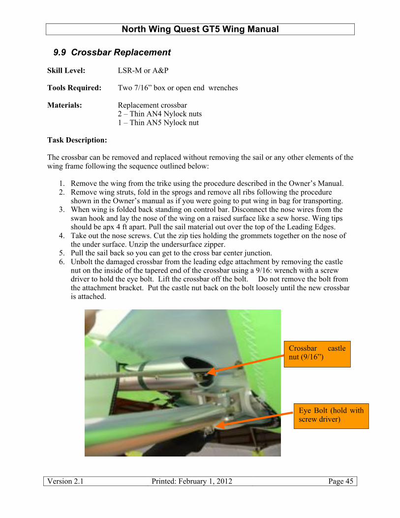
5. Pull the sail back so you can get to the cross bar center junction. 6. Unbolt the damaged crossbar from the leading edge attachment by removing the castle
nut on the inside of the tapered end of the crossbar using a 9/16: wrench with a screw driver to hold the eye bolt. Lift the crossbar off the bolt. Do not remove the bolt from the attachment bracket. Put the castle nut back on the bolt loosely until the new crossbar is attached.
Eye Bolt (hold with screw driver)
Crossbar castle nut (9/16”)

North Wing Quest GT5 Wing Manual
Version 2.1 Printed: February 1, 2012 Page 46
1. Unbolt the crossbar from the crossbar center plate, and slide the crossbar free of the wing. To do this, it is necessary to slide a 7/16” wrench inside the crossbar to hold the nut from turning since the bolt does not go all the way through the cross bar. Note the sequence of the spacers and washer inside the crossbar. We use a box end wrench with a small round magnet glued to one side of the wrench. This allows us to reinstall the nut and washers with ease. You can also use a piece of tape to close one end of the box end wrench.
Re-assembly Note: Re-assemble in reverse order. Again you most likely will not get the sail mount screws back in the nose until you completely assemble the wing. To make set up easier put a line through the sail grommets and around the nose plate and pull tension on the sail leading edges. When re-assembling, remember to use a safety pin or ring on the castle nut on the crossbar attachment to the leading edge bracket. Also pay attention not to miss the black cross bar restraint webbing that goes under the crossbar plate.
9.10 Front and Rear Pitch Cables (Lower Rigging) Replacement Skill Level: Owner or higher Tools Required: Two 7/16” box or open end wrenches Materials: Replacement cables 3 – "” Thin Nylock nuts Task Description:
Crossbar center plate bolts looking from front side
Crossbar center plate looking from back side

North Wing Quest GT5 Wing Manual
Version 2.1 Printed: February 1, 2012 Page 47
The front and rear pitch cables and mounting tangs come as two separate cable assemblies. Although they can be replaced separately if damaged, it is recommended both assemblies be replaced at the same time. These cables should be replaced every 400 hours of flight time or if any one of them becomes kinked or shows any sign of wear or abrasion.
1. Remove the wing from the trike using the procedure described in the Owner’s Manual 2. Remove wing struts, fold in the sprogs and remove all ribs following the procedure
shown in the Owner’s manual as if you were going to put wing in bag for transporting. 3. With the wing still spread open you can unhook the nose wires and left the nose of the
wing and fold the control bar back under the wing. Now bring the nose down and rest on top of a sew horse.
4. Remove cable attachment bolt at rear of keel tube. Inspect the bolt and replace bolt and nut if any signs of wear on the bolt.
5. Remove cable at lower control bar attachment point. Also inspect bolt for ware, replace if needed. Always replace nylock nuts, never reuse nylock nuts.
6. Replace the new cables and reassemble wing.
Lower front and rear cables attachment to downtube
Rear lower cables & tangs attached to keel tube
North Wing Quest GT5 Wing Manual
Version 2.1 Printed: February 1, 2012 Page 48
9.11 Owner Replaceable Wing Fittings and Hardware Skill Level: Owner or higher Tools Required: Two 7/16” box or open end wrenches Materials: Replacement Fittings and Hardware Task Description: The wing fittings and hardware listed below can be replaced by the owner.
• Sprog attachment hardware • Front swan hook attachment • Pull back cable attachment hardware (Bailey spring latch) • Control bar frame tubes
In all cases replacement of this hardware requires the removal of the wing from the trike. The common element among these items is that they all attach to the tubing and care must be taken to avoid over tightening bolts and thereby crushing or distorting the tubing excessively.
1. Remove wing ribs 2. Spread wing on clean floor or ground surface upside down. 3. Open wing zipper or nose cone to expose part to be replaced. 4. Remove safety wire and bolts securing hardware to wing tubes taking particular care to
note the sequence of washers, saddles, and nut positions. 5. Replace the worn or damaged part checking the holes in the tubing at the same time for
wear or fatigue cracks. 6. Replace the bolts and nylock nuts with new ones if there is any sign of wear. Always
install new nylock nuts. Tighten the bolts to SNUG (no slack plus " turn) making sure the tubing is not distorted which would weaken the tube.

North Wing Quest GT5 Wing Manual
Version 2.1 Printed: February 1, 2012 Page 49
9.12 Non-Owner Replaceable Wing Fittings and Hardware Skill Level: LSR-M or A&P Tools Required: Two 7/16” box or open end wrenches Materials: Replacement Fittings and Hardware Task Description: The wing fittings and hardware listed below must be replaced by an authorized mechanic.
• Nose plates • Cross bar plates • Crossbar to leading edge attachment hardware
The procedure for this task is the same as for Owner Replaceable hardware above and it is repeated here. In all cases replacement of this hardware requires the removal of the wing from the trike. The common element among these items is that they all attach to the tubing and care must be taken to avoid over tightening bolts and thereby crushing or distorting the tubing excessively.
7. Remove wing ribs 8. Spread wing on clean floor or ground surface upside down. 9. Open wing zipper or nose cone to expose part to be replaced. 10. Remove safety wire and bolts securing hardware to wing tubes taking particular care to
note the sequence of washers, saddles, and nut positions. 11. Replace the worn or damaged part checking the holes in the tubing at the same time for
wear or fatigue cracks. 12. Replace the bolts and nylock nuts with new ones if there is any sign of wear. Always
install new nylock nuts. Tighten the bolts to SNUG making sure the tubing is not distorted excessively which would weaken the tube.

North Wing Quest GT5 Wing Manual
Version 2.1 Printed: February 1, 2012 Page 50
10. Transportation and Storage The Quest GT5 should always be stored with the zipper facing down, especially during transportation. With the wing riding this way, the sail is sitting on the tubing rather than the tubing sitting (and bouncing) on the sail. This will significantly reduce the possibility of vibration/wear damage during transport. Additionally, with the zipper down less water will get into the cover bag in case of rain. Avoid hard spots pressing on the wing during transportation or storage and have as many supports as possible; we recommend using a well padded three-point support system, with less than four feet of unsupported wing extending off either end. Use flat tie down straps, at least 1” width (available through North Wing) rather than elastic or rope to secure the wing, and tie both ends of the wing to a support or down to the ends of the vehicle in order to prevent the wing from flexing. Take care to not over tighten the wing tie-downs, as this can crimp your Mylar leading edges. A good technique is to squeeze and compress the mylar, sail, and leading edges into a snug bundle by hand as it gets tied down, rather than using the wing tie-downs to compress the wing within the bag. It is preferable to keep the wing dry. Definitely ensure that it is dry before storing for longer than just overnight. Any contact with salt water, of course, requires immediate rinsing with fresh water to prevent corrosion to hardware, rigging and tubes. 11. Wing Retirement With proper care and maintenance, the Quest GT5 will remain for some years at a high level of airworthiness. Each Quest GT5 has a patch sewn into the sail at the top center for UV testing. Simply cut out the panel and have a test performed. There is much that we still don’t know about trike wing longevity; such as what exactly is the effective lifetime of a trike wing before material fatigue and degradation compromise the airworthiness of that wing. We do know that there are forces in nature which can severely compromise the airworthiness of that wing, regardless of the quality of design or condition of the wing you are operating. Your safety is ultimately your own responsibility. However, there is one subject in particular which needs to be addressed at this point--and this is wing retirement. There comes a time when the sail of any trike wing simply becomes too suspect to feel safe while flying it. Ultraviolet degradation will inevitably dictate the retirement of your wing. Judging when this occurs to your wing is best verified by an authorized service center. All of us, as responsible and caring human beings, owe it to one another to do the responsible thing and remove any over-used equipment from the skies. We at North Wing abhor those whose method of dealing with a wing due for retirement consists of simply passing their problem along to an unsuspecting pilot in the used wing market place. The mature thing to do, at the appropriate time, is to destroy very old gliders to ensure that they cannot endanger an unknowing pilot.

North Wing Quest GT5 Wing Manual
Version 2.1 Printed: February 1, 2012 Page 51
Along these same lines, because wings do change hands, we feel that it is quite important to keep accurate records of tuning changes, and especially of repairs, in the maintenance log of this manual. Please consider the needs and safety of those other pilots down the road who may stand to gain from these records. 12. Limitation of Liability The owner and operator of this trike wing must understand that, due to the inherent risk involved in flying such a unique vehicle, no warranty is made or implied of any kind against accidents, bodily injury, or death. Practiced even under the best circumstances, trike flying is a high-risk sport. By purchasing this wing, the owner and operator of this Trike wing assumes complete responsibility for their use of this equipment, and specifically, agrees to release North Wing and/or their agents, from any and all liability. 13. Owner’s Maintenance Log DATE WORK PERFORMED ____________________________________________________________________________________________________________________________________________________________________________________________________________________________________________________________________________________________________________________________________________________________________________________________________________________________________________________________________________________________________________________________________________________________________________________________________________________________________________________________________________________________________________________________________________________________________________________________________________________________________________________________________________________________________________________________________________________________________________________________________________________________________________________________________________________________________________________________________________________________________________________________________________________________________________________________________________________________________________________________________________________________________________________________________________________________________________________________________________________________________________________________________________________________________________________________________
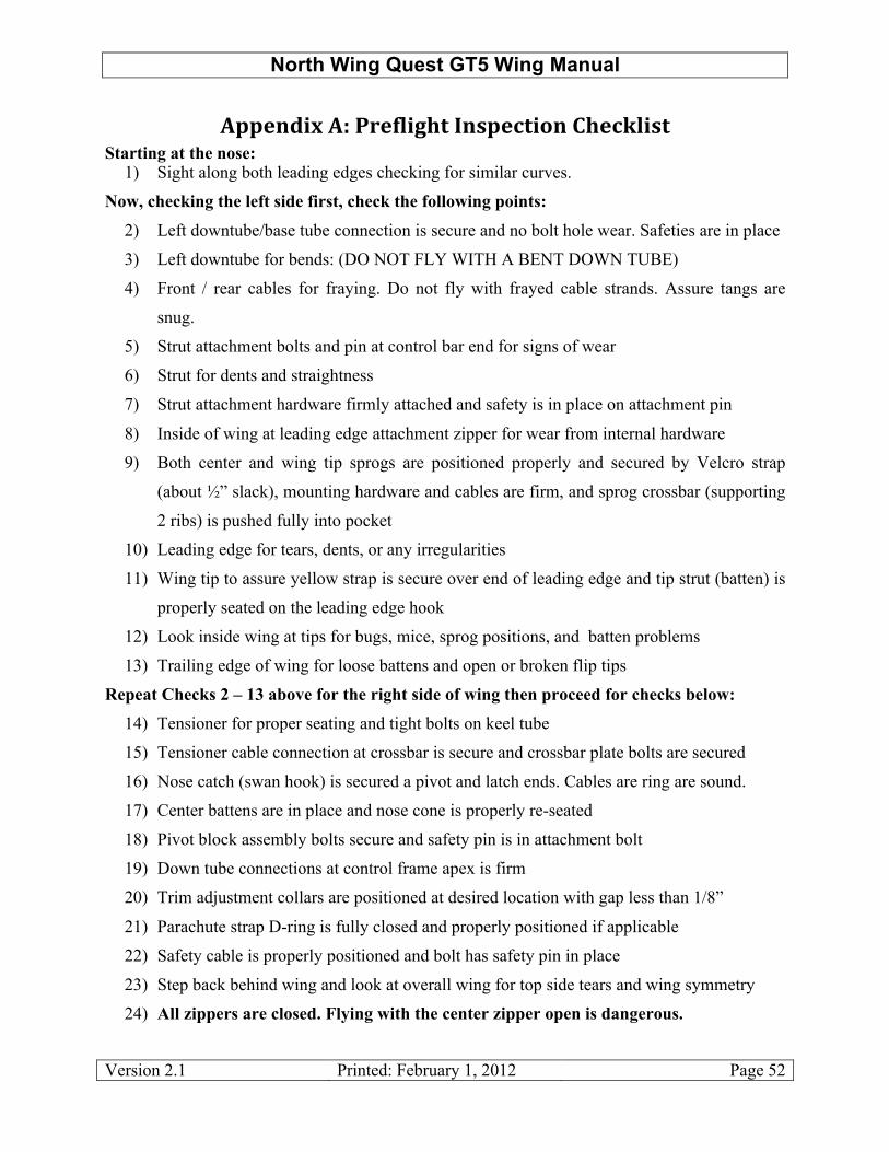
North Wing Quest GT5 Wing Manual
Version 2.1 Printed: February 1, 2012 Page 52
!""#$%&'(!)(*+#,-&./0(1$2"#30&4$(5/#36-&20(Starting at the nose:
1) Sight along both leading edges checking for similar curves.
Now, checking the left side first, check the following points: 2) Left downtube/base tube connection is secure and no bolt hole wear. Safeties are in place
3) Left downtube for bends: (DO NOT FLY WITH A BENT DOWN TUBE)
4) Front / rear cables for fraying. Do not fly with frayed cable strands. Assure tangs are
snug.
5) Strut attachment bolts and pin at control bar end for signs of wear
6) Strut for dents and straightness
7) Strut attachment hardware firmly attached and safety is in place on attachment pin
8) Inside of wing at leading edge attachment zipper for wear from internal hardware
9) Both center and wing tip sprogs are positioned properly and secured by Velcro strap
(about !” slack), mounting hardware and cables are firm, and sprog crossbar (supporting
2 ribs) is pushed fully into pocket
10) Leading edge for tears, dents, or any irregularities
11) Wing tip to assure yellow strap is secure over end of leading edge and tip strut (batten) is
properly seated on the leading edge hook
12) Look inside wing at tips for bugs, mice, sprog positions, and batten problems
13) Trailing edge of wing for loose battens and open or broken flip tips
Repeat Checks 2 – 13 above for the right side of wing then proceed for checks below: 14) Tensioner for proper seating and tight bolts on keel tube
15) Tensioner cable connection at crossbar is secure and crossbar plate bolts are secured
16) Nose catch (swan hook) is secured a pivot and latch ends. Cables are ring are sound.
17) Center battens are in place and nose cone is properly re-seated
18) Pivot block assembly bolts secure and safety pin is in attachment bolt
19) Down tube connections at control frame apex is firm
20) Trim adjustment collars are positioned at desired location with gap less than 1/8”
21) Parachute strap D-ring is fully closed and properly positioned if applicable
22) Safety cable is properly positioned and bolt has safety pin in place
23) Step back behind wing and look at overall wing for top side tears and wing symmetry
24) All zippers are closed. Flying with the center zipper open is dangerous.