Embed Size (px)
DESCRIPTION
NDT testing to evualuate post tensioning tendons in concrete
Citation preview

KSCE Journal of Civil Engineering (2012) 16(3):388-397DOI 10.1007/s12205-012-1295-0
− 388 −
www.springer.com/12205
Structural Engineering
Non-Destructive Testing Methods to Identify Voids inExternal Post-Tensioned Tendons
Seok Been Im* and Stefan Hurlebaus**
Received August 18, 2010/Revised June 6, 2011/Accepted June 23, 2011
···································································································································································································································
Abstract
A considerable number of Post-Tensioned (PT) bridges have been constructed because PT systems enable them to carry significanttraffic loads and have an aesthetical structure. However, strand corrosion has been a long-standing issue because it may lead to thefailure of tendons and the deterioration of structural performance. The corrosion typically occurs in voided locations with exposedstrands; thus, the inspection of voids in external PT tendons is important and necessary in order to protect strands before corrosionoccurs. Based on literature review, several Non-Destructive Testing (NDT) methods are compared for effectiveness of identifyingvoids in external PT tendons, and the Impact Echo (IE), ultrasonic, and sounding inspection methods are then selected and assessedusing small-scale and mock-up specimens. From the experimental results, the wave-based inspection methods, IE and ultrasonicmethods, are difficult to apply in the field because the imperfect bonds between ducts and grouts obstruct the transmission of waves.However, the sounding inspection method is not affected by the discontinuities and successfully identifies voids in test specimens.Thus, the sounding inspection can be an effective tool for identifying voids because of its easy application in the field.Keywords: post-tensioned bridge, void, external tendon, impact echo, ultrasonic, sounding inspection
···································································································································································································································
1. Introduction
Post-Tensioned (PT) structural elements are used quite often inbridges due to their ability to economically span long widths whileproviding an aesthetically pleasing structure. In addition, the useof PT systems in long span bridges has become influential asthey reduce the overall cost of the substructure. This is especiallysignificant when substructure costs increase due to complexitiesin span conditions such as bridges spanning seas, valleys, andurban areas. PT systems are also preferred in bridge constructionbecause they greatly increase structural capacities and are fairlyeasy to implement effectively.
The construction of a basic PT system consists of placing steelprestressing tendons in ducts which are entirely or partially em-bedded in concrete structures. Once the concrete element hashardened, the tendons are tensioned and as a result an overallcompression force is exerted on the concrete. The compressivestresses induced by the PT tendons are advantageous since theyreduce or perhaps even eliminate tensile stresses, which concretehas little strength to resist. These systems make it feasible andmore economical to use concrete for long span bridge structures.PT systems can be used not only for new bridge construction butalso for the rehabilitation and strengthening of existing bridges.
PT bridge systems can include both external and internal post-
tensioned tendons. While the internal PT tendons are embeddedin concrete structures with sheath ducts, the external PT tendonsare installed inside box girders with High-Density Poly-Ethylene(HDPE) ducts. The external PT tendons are typically utilized toreduce the congestion between reinforcing steel and internaltendons. Along with reducing congestion external tendons arealso advantageous since they are easier to inspect and replacethan the internal PT tendons.
The advantages of PT structures may not be realized if they donot achieve their designed service lives, which is typically over75 years. Exposure to harsh environments contributes to the earlydeterioration of PT structures. In order to protect PT strands fromearly deterioration, they are placed in ducts and cementitiousmaterials are grouted into the areas between the steel strands andthe internal surface of the duct. The combination of the duct andthe cementitious material provides a protective system for thestrands against the most aggressive contributors to steel deter-ioration, corrosion.
Although PT systems provide many advantages for designersand constructors, corrosion of the PT strands has raised manyconcerns about the longevity of these structural systems. Unlikeconventional reinforced concrete systems, in which corrosiondistress can be identified by the observation of excessive stain-ing, cracking, or spalling of the concrete cover, corroding PT
*Member, Manager, Bridge and Structure, Civil Engineering Center, Samsung C&T Corporation, Seoul 137-858, Korea (Corresponding Author, E-mail:[email protected])
**Associate Professor, Zachry Dept. of Civil Engineering, Texas A&M University, TX77843, USA (E-mail: [email protected])

Non-Destructive Testing Methods to Identify Voids in External Post-Tensioned Tendons
Vol. 16, No. 3 / March 2012 − 389 −
systems seldom show these surface distress indicators. Theseindicators are not visible in PT tendons since the tendons areembedded in ducts and are away from the external surface of thestructure. The difficulty in identifying tendon distress is parti-cularly problematic since the degree of corrosion is critical to thestructural performance of PT elements. In 1967, the suddencollapse of the Bickton Meadows Footbridge in the UK raisedconcerns about the durability of PT bridges, while the failure ofYns-y-Gwas Bridge in Wales, UK, further emphasized the severityof corrosion in PT systems (Pearson-Kirk, 2003; Raiss, 1995;Schokker et al., 2001). Recently, the investigated failures of anexternal tendon in the Mid-Bay Bridge and a vertical loop tendonin the Sunshine Skyway Bridge once again called attention todeficiencies in the inspection and maintenance methods ofgrouted ducts in PT structures (Corven, 2001; Pielstick, 2002).The Virginia Department of Transportation (VDOT) reportedfailures in external PT tendons in the Varina-Enon Bridge in2007. Consequently, they emphasized the need for an appropri-ate health monitoring system in PT elements based on a failureanalysis (Sprinkel and Napier, 2008). The corrosion issue in PTsystems has been identified in ducts with voids, and these voidsin PT bridges are typically formed by entrapped air pockets,grout bleeding, and/or improper grouting (PCI, 1997; Im et al.,2010a; Trejo et al., 2009; Woodward and Miller, 1990). Recentlyconducted investigations in PT bridges reported that groutedexternal tendons commonly have voids inside the ducts (Pearson-Kirk, 2003; Woodward and Miller, 1990; Im et al., 2010b; ASBI,2000; FDOT, 1999; FDOT, 2001; Hansen, 2007). Thus, currentPT bridges may have voids in their PT element and it can be apotential source of severe corrosion under certain critical environ-mental conditions. While voids in grouted ducts can cause signi-ficant and long-standing issues for structural integrity of externalPT tendon systems, little research has been conducted on how toeffectively investigate these voids which may be a route fordeteriorate sources that induce corrosion.
2. Non-Destructive Testing Methods
In recent years, a considerable amount of research on Non-Destructive Testing (NDT) has been conducted to identify thelocations and severity of damage in structures. Although muchresearch have shown successful results in the laboratory, theapplication of NDT methods in the field is still challenging becauseof the noise generated during field measurements, confined andlimited field conditions for measurement, and other reasons.Thus, an effective NDT method in the field needs to consider thefollowing criteria: 1) reliable measurement, 2) high speed mea-surement, 3) ease of application, and 4) low cost. To provide afeasible NDT method for external PT tendons, a review ofvarious NDT methods used in civil engineering applications isperformed as follows.
2.1 Sounding TechniqueFor the inspection of external PT ducts, a sounding inspection
is generally performed to identify the existence of voids inducts (Corven, 2001). Although the sounding inspection issubjective, it is easy to execute in the field and is a relativelyrapid method for detecting voids in ducts. Also, this inspectionis particularly effective in the field because it can be appliedwithout a power supply. In addition, sounding inspectionfindings can be supported by the borescope inspection (Corven,2001).
2.2 Impact-Echo TechniqueThe Impact-Echo (IE) method uses mechanical impacts to
generate stress pulses in concrete structures. This method hasbeen studied by several researchers (Carino and Sansalone,1990; Carino and Sansalone, 1992; Pessiki and Carino, 1988;Sansalone and Carion, 1989) and has yielded successful mea-surements for flaw detection. Because the impact generates ahigh energy pulse and can penetrate deep into the concrete struc-tures, the IE method is particularly promising in the applicationof NDT methods. In addition, it produces a better signal-to-noiseratio than other ultrasonic techniques because of its low attenua-tion in composite materials such as concrete (Karaoguz et al.,1998). Carino and Sansalone applied the IE method to detectsimulated voids in grouted post-tensioning ducts which werelocated in a 3.3 ft (1 m) thick concrete wall specimen (Carinoand Sansalone, 1992). Although the IE method can makemeasurements for flaw detection and thickness, it is difficult toproduce an image of the structure as well as to directly apply insmall grouted ducts such as external tendons. Moreover, the IEmethod is rather time-intensive for inspection of large specimens.To resolve this limitation, a movable IE scanner system wasdeveloped by Tinkey et al. (2005). The scanning system wasapplied to internal ducts. However, it was difficult to detect voidswhen the concrete cover was thicker than the diameter of theembedded ducts. Also, the IE scanner system is incapable ofidentifying voids when the ducts are partially filled with water(Tinkey et al., 2005). The authors then applied a movablescanning system to the mock-up slab and girder which includedvoided ducts simulated by pieces of Styrofoam (Tinkey andOlson, 2007). However, the scanning system could not detectvoids well when the diameter of the ducts was small and theconcrete covers were thick.
2.3 Ultrasonic TechniqueUltrasonics is defined as the study dealing with sounds having
a frequency of 18 kHz and higher (Biltz and Simpson, 1996).The ultrasonic technique can be used in concrete structures toidentify concrete thickness (Krause et al., 1995), elastic modulus,and detect flaws such as cracks, voids, etc., (Schickert, 1995).Martin et al. (2001) performed tests on 1.6 inch (40 mm) internalgrouted duct specimens with simulated voids by measuring thetime-of-flight of transmitted pulses. These tests required the useof several receivers in a grid pattern on the surface of specimens.Although this technique depicted successful results for detectingvoids in PT concrete beams, it is relatively time-consuming and
Seok Been Im and Stefan Hurlebaus
− 390 − KSCE Journal of Civil Engineering
costly because of the large number of transducers required. Iyeret al. (2003; 2005) evaluated the ultrasonic C-scan imagingsystem to verify the detection of corrosion and voids in specimens.The specimens were grouted in square PVC ducts with onestrand in the center and scanning was conducted underwater.Two different levels of corrosion and voids in specimens wereidentified using the C-scan. During application, ultrasonic methodcontact transducers are typically used, and a couplant, a stickyresin, needs to be placed between the surface of specimens andthe transducers. Thus, the use of the couplant or other substitu-tive materials is inconvenient when applying the ultrasonic methodin the field.
Although the application of ultrasonic techniques are limitedin real structures, they can be promising if limitations can beresolved. Alternatives have been studied that involve non-contact ultrasonic systems such as air-coupled ultrasound(Martínez et al., 2003; Mendelsohn and Wiener-Avnear, 2002),point-contact sensors (Kozlov et al., 2006; Schickert et al.,2003; Schickert, 2005), or laser ultrasound (Kil et al., 1998;Scruby and Drain, 1990). Air-coupled ultrasound works typi-cally in the frequency range of 50 to 100 kHz for application inconcrete structures; however, it has the disadvantage of lowsignal amplitudes due to the impedance mismatch between theinterfaces (transducer-air-specimen). Consequently, Blum (2003)studied increased signal amplitude using several air-coupledultrasonic transducers combined into an array for generation ofultrasound. Recently, point-contact sensors were developedwhich do not require any coupling agent for ultrasonic mea-surements (Kozlov et al., 2006). To create better resolution andreduce the noise from the obtained signals, the ultrasonic methodwith point-contact sensors utilizes the Synthetic Aperture FocusingTechnique (SAFT) (Schickert et al., 2003). Comparing withconventional transducers, however, it is still challenging toobtain reliable data (Schickert, 2005).
Laser ultrasonics may be used for the generation and detectionof elastic waves. These laser techniques provide numerous benefitsover conventional piezoelectric techniques (Hurlebaus et al.,1998). Because optical techniques are non-contact techniques,they do not cause any errors associated with couplant thicknessand/or applied pressure which is present when contact piezoelec-tric transducers are used. Couplants on the specimen surface cancause small changes in observed arrival times of surface acousticwaves. These small errors can become critical when the measuredvelocities are used in calculation for the localization of disconti-nuities. Another benefit of optical methods is that they are pointtechniques which may be used on any specimen regardless ofsize or geometry. A laser source provides the benefit of beingbroadband; that is, the resulting signal has components over awide frequency bandwidth. Finally, using laser detection has thebenefit of making absolute measurements with high fidelity(resonance free). However, this technique is sensitive to the sur-face condition of the test specimen. In addition, the use of laserultrasonics is expensive and its application in the field is difficultdue to laser safety requirements.
2.4 Magnetic Flux Leakage TechniqueThe Magnetic Flux Leakage (MFL) technique is a promising
technique in the NDT&E field because it is capable of detectingcorrosion in embedded steels or metallic materials. This techniqueemploys the use of magnetic field sensors called Superconduct-ing Quantum Interference Devices (SQUIDS). These sensors arerelatively sensitive and have a large dynamic range for inspec-tion. Krause et al. (2001) studied the inspection of rupturedtendons in pre-stressed concrete structures using a SQUID system.It was reported that the MFL method was applied successfully tothe detection of corrosion in external polymer ducts (Tilly, 2002).Although the MFL technique is effective in detecting corrosionin metallic materials, it cannot evaluate other discontinuities suchas voids and cracks. To prevent tendons from corroding, it isnecessary to identify the existence of voids before severe corrosionin tendons occurs.
2.5 Computerized Tomography Technique Using X-rayComputerized Tomography (CT) is a technique used to
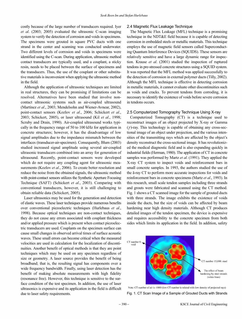
reconstruct images of an object projected by X-ray or Gamma(γ )-ray. This technology is capable of obtaining any cross-sec-tional image of an object under projection, and the various inten-sities of the transmitting rays which are affected by the object’sdensity reconstruct the cross-sectional image. It has revolutioniz-ed the medical diagnostic field and is also expanding quickly inindustrial fields (Herman, 1980). The application of CT in concretesamples was performed by Martz et al. (1991). They applied theX-ray CT system to inspect voids and reinforcement bars insmall concrete samples. In 1993, the authors studied the use ofthe ã-ray CT to perform more accurate inspections for voids andreinforcement bars in concrete specimens (Martz et al., 1993). Inthis research, small scale tendon samples including three strandsand grouts were fabricated and scanned using the CT method.Fig. 1 shows a CT scanned image for the sample of grouted ductswith three strands. The image exhibits the existence of voidsinside the ducts, but the size of voids can be affected by beamhardening near high density materials. Although CT producesdetailed images of the tendon specimen, the device is expensiveand requires accessibility to the concrete specimen from bothsides which limits its application in the field. In addition, safety
Fig. 1. CT Scan Image of a Sample of Grouted Ducts with Strands

Non-Destructive Testing Methods to Identify Voids in External Post-Tensioned Tendons
Vol. 16, No. 3 / March 2012 − 391 −
requirements for the excessive exposure to radiation have to beresolved before applying the CT method in the field.
2.6 Electrical Capacitance TomographyRecently, a great amount of research using electric character-
istics has been performed on NDT methods. Time-Domain Re-flectometry (TDR) using electromagnetic waves has been studi-ed for detecting voids around strands (Li et al., 2005). However,this technique requires access to strands in order to make thetwo-wire transmission line. Electrical Capacitance Tomography(ECT) has been studied and applied to reconstruct cross-sectional images of oil flow inside the non-conductive pipe line(Ortiz-Alemán and Martin, 2005a). The ECT can obtaincapacity data from multi-electrode sensors, and data by severalthousands of iterations make the permittivity images in sections.These images can show the existence of air in oil flows (Ortiz-Alemán and Martin, 2005a). This application of the ECT is oneof the most promising tomography techniques because it is safe,has a fast response rate, and is relatively inexpensive (Ortiz-Alemán and Martin, 2005b; Yang, 1997). Although this electri-cal method produces low resolution images of sections, optimiz-ed data processing enables the image to be enhanced (Gamio etal., 2005). Similar capacitance methods have been applied fordetecting voids in HDPE ducts (Iaquinta, 2004). The investigatorsattached a pair of electrodes on a small-sized HDPE duct thatincluded one strand, and obtained successful results for iden-tifying voids and water-filled voids in ducts. Fig. 2 shows theprinciple of ECT sensors on HDPE ducts. However, the designof ECT is complicated when it comes to obtaining successfulestimation; thus, careful design and thorough verification arerequired.
3. Preliminary Testing on Small-Scale Specimens
Based on the literature review, the IE method, ultrasonic method,and sounding method are assessed using small and large scaletest specimens. First, the IE and ultrasonic techniques are selectedand assessed for preliminary testing. Secondly, the IE and sound-ing methods are tested using mock-up specimens representing afield condition.
Sixteen small-scale test specimens are fabricated and testedusing the IE and Ultrasonic methods (Fig. 3). The ultrasonicmethod is applied using the pitch-catch method, and the testing
system consists of oscilloscope (TDS 3034B), power amplifier(Panametrics), and a pair of 50 kHz transducers (Panametrics).The IE method is performed using a Portable Impact EchoSystem (PIES), a commercial NDT package, and the testingsystem consists of iPaq computer, digitizer, battery, transducer,and impactors. The ultrasonic and IE methods are applied to thetest locations from Lo1 to Lo11 (Fig. 3) and eight points at eachlocation are examined along the perimeter of the duct.
Figures 4 and 5 exhibit the output data in the frequencydomain obtained from the IE and ultrasonic methods, but theseNDT techniques are found to be ineffective in detecting voids inthe small-scale test specimens. The figures show that there is nocritical difference at the void location, Lo6. This is because theinterface between the HDPE ducts and cementitious grout ob-structed the elastic waves used in these techniques. In addition,the ultrasonics using contact transducers requires a couplantbetween the transducers and the surface of the specimens. This isa time-consuming process and probably impractical for use onlong tendon systems in PT bridges. As a result, ultrasonic tech-
Fig. 2. The Principle of Electrical Capacitance TomographyFig. 3. Small-Scale Test Specimen for Preliminary Test
Fig. 4. Inspection Results Using Ultrasonic Method
Fig. 5. Inspection Results Using Impact Echo Method

Seok Been Im and Stefan Hurlebaus
− 392 − KSCE Journal of Civil Engineering
niques are determined not to be advantageous to full-scalespecimens.
4. Full-Scale Experimental Test Setup
External PT tendon systems are typically installed in a harpedshape in the field because this can reduce or eliminate positiveflexural moments acting on the mid-span and negative flexuralmoments at both end-spans in continuous span bridges. Based onthe recent inspections of PT bridges by the researchers, voidsusually exist in the external PT systems near end anchoragezones.
To simulate void cases in the field, half of a harped tendonsystem is designed and fabricated with improper grouting. Theschematic of the experimental specimen is shown in Fig. 6.
First, the full-scale experimental setup is tensioned by 19strands and 0.3% of their ultimate tensile strength (0.8 ksi, 5.52MPa) is applied to straighten the strands and mimic fieldconditions. The strands are located inside a 4 inch (0.1 m)diameter duct made of transparent acrylic plastic. After stressingthe strands, the interstitial spaces between the stands and ductwere filled with Class A grout (cement and water with a water-cement ratio (w/c) of 0.44) to consider the effect of bleeding.Artificial voids are then intentionally formed in the topanchorage zone and at five locations along the duct to simulateimproper grouting procedures (Fig. 6).
As shown in Fig. 6, the main void at the top anchorage zoneand the five other small voids along the duct are connected bya top surface void line along the duct. These void lines arecalled “bleed lines” (also known as “bug holes”) and areformed by the evaporation of bleed water from the grout andentrapped air pockets (PCI, 1997). A total of 15 experimentalspecimens are tested for assessing the IE and soundinginspection methods.
5. Experimental Results: The IE Method
To identify the existence of tiny discontinuities on full-scalespecimens, the IE method is applied to the specimens. The IEmethod utilizes the PIES system, and randomly selected locationsalong the entire specimen are examined. The IE methodidentifies the tiny discontinuities between ducts and grouts at thelocations, and the following four locations in Fig. 7 are selectedand tested for the in-depth inspection. From the figure, Lo1 andLo2 are located in main voids, and Lo1 indicates a large void,
almost partially filled, and Lo2 is a small void which means thattwo or three top strands are exposed. Lo6 just has a bleed lineindicating that strands are not exposed at all and may have a tinygap due to shrinkage. Lo7 is the location of a local void which isintentionally formed to simulate a void due to the entrapped air.The selected locations are examined along the perimeter of theducts.
Figure 8 exhibits the results obtained from the IE system. Theresults appear to have irregular peak frequencies but it seems thatthere is no critical difference among different void sizes. Thisindicates that waves generated by impact are not passing throughthe duct because of tiny gaps between ducts and grouts, and thewaves are transmitted around the ducts.
The voided specimens are then repaired with high performanceand non-shrinkage grouts, commercially available pre-packagedgrouts. The grouts are injected from the grout port at the upperanchorage and they successfully fill voids along the ducts aspassing Lo7. The IE test is then performed again at the samelocations, Lo1, 2, 6, and 7.
Figure 9 shows the results obtained from the IE system, and
Fig. 6. Full-Scale Experimental Setup Showing Void Locations
Fig. 7. Testing Locations of Impact Echo Method
Fig. 8. Results Obtained from Full-Scale Specimen before RepairGrouting
Fig. 9. Results Obtained from Full-Scale Specimen after RepairGrouting
Non-Destructive Testing Methods to Identify Voids in External Post-Tensioned Tendons
Vol. 16, No. 3 / March 2012 − 393 −
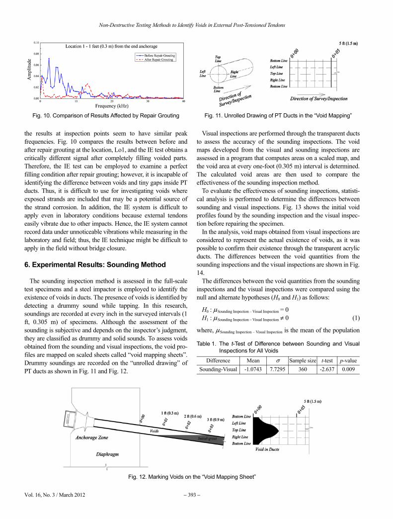
the results at inspection points seem to have similar peakfrequencies. Fig. 10 compares the results between before andafter repair grouting at the location, Lo1, and the IE test obtains acritically different signal after completely filling voided parts.Therefore, the IE test can be employed to examine a perfectfilling condition after repair grouting; however, it is incapable ofidentifying the difference between voids and tiny gaps inside PTducts. Thus, it is difficult to use for investigating voids whereexposed strands are included that may be a potential source ofthe strand corrosion. In addition, the IE system is difficult toapply even in laboratory conditions because external tendonseasily vibrate due to other impacts. Hence, the IE system cannotrecord data under unnoticeable vibrations while measuring in thelaboratory and field; thus, the IE technique might be difficult toapply in the field without bridge closure.
6. Experimental Results: Sounding Method
The sounding inspection method is assessed in the full-scaletest specimens and a steel impactor is employed to identify theexistence of voids in ducts. The presence of voids is identified bydetecting a drummy sound while tapping. In this research,soundings are recorded at every inch in the surveyed intervals (1ft, 0.305 m) of specimens. Although the assessment of thesounding is subjective and depends on the inspector’s judgment,they are classified as drummy and solid sounds. To assess voidsobtained from the sounding and visual inspections, the void pro-files are mapped on scaled sheets called “void mapping sheets”.Drummy soundings are recorded on the “unrolled drawing” ofPT ducts as shown in Fig. 11 and Fig. 12.
Visual inspections are performed through the transparent ductsto assess the accuracy of the sounding inspections. The voidmaps developed from the visual and sounding inspections areassessed in a program that computes areas on a scaled map, andthe void area at every one-foot (0.305 m) interval is determined.The calculated void areas are then used to compare theeffectiveness of the sounding inspection method.
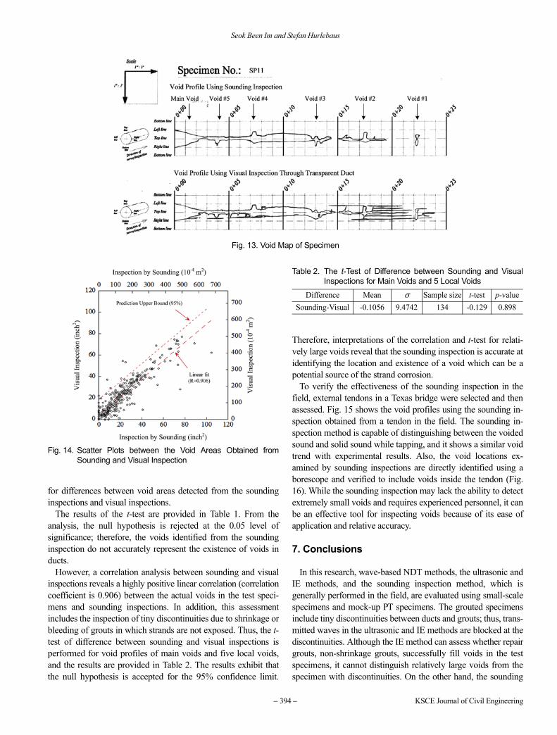
To evaluate the effectiveness of sounding inspections, statisti-cal analysis is performed to determine the differences betweensounding and visual inspections. Fig. 13 shows the initial voidprofiles found by the sounding inspection and the visual inspec-tion before repairing the specimen.
In the analysis, void maps obtained from visual inspections areconsidered to represent the actual existence of voids, as it waspossible to confirm their existence through the transparent acrylicducts. The differences between the void quantities from thesounding inspections and the visual inspections are shown in Fig.14.
The differences between the void quantities from the soundinginspections and the visual inspections were compared using thenull and alternate hypotheses (H0 and H1) as follows:
H0 : µSounding Inspection – Visual Inspection = 0H1 : µSounding Inspection – Visual Inspection ≠ 0 (1)
where, µSounding Inspection – Visual Inspection is the mean of the population
Fig. 10. Comparison of Results Affected by Repair Grouting Fig. 11. Unrolled Drawing of PT Ducts in the “Void Mapping”
Fig. 12. Marking Voids on the “Void Mapping Sheet”
Table 1. The t-Test of Difference between Sounding and VisualInspections for All Voids
Difference Mean σ Sample size t-test p-valueSounding-Visual -1.0743 7.7295 360 -2.637 0.009
Seok Been Im and Stefan Hurlebaus
− 394 − KSCE Journal of Civil Engineering
for differences between void areas detected from the soundinginspections and visual inspections.
The results of the t-test are provided in Table 1. From theanalysis, the null hypothesis is rejected at the 0.05 level ofsignificance; therefore, the voids identified from the soundinginspection do not accurately represent the existence of voids inducts.
However, a correlation analysis between sounding and visualinspections reveals a highly positive linear correlation (correlationcoefficient is 0.906) between the actual voids in the test speci-mens and sounding inspections. In addition, this assessmentincludes the inspection of tiny discontinuities due to shrinkage orbleeding of grouts in which strands are not exposed. Thus, the t-test of difference between sounding and visual inspections isperformed for void profiles of main voids and five local voids,and the results are provided in Table 2. The results exhibit thatthe null hypothesis is accepted for the 95% confidence limit.
Therefore, interpretations of the correlation and t-test for relati-vely large voids reveal that the sounding inspection is accurate atidentifying the location and existence of a void which can be apotential source of the strand corrosion.
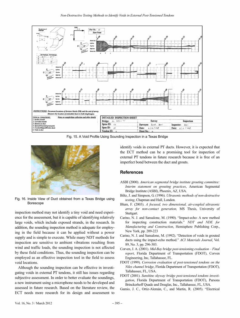
To verify the effectiveness of the sounding inspection in thefield, external tendons in a Texas bridge were selected and thenassessed. Fig. 15 shows the void profiles using the sounding in-spection obtained from a tendon in the field. The sounding in-spection method is capable of distinguishing between the voidedsound and solid sound while tapping, and it shows a similar voidtrend with experimental results. Also, the void locations ex-amined by sounding inspections are directly identified using aborescope and verified to include voids inside the tendon (Fig.16). While the sounding inspection may lack the ability to detectextremely small voids and requires experienced personnel, it canbe an effective tool for inspecting voids because of its ease ofapplication and relative accuracy.
7. Conclusions
In this research, wave-based NDT methods, the ultrasonic andIE methods, and the sounding inspection method, which isgenerally performed in the field, are evaluated using small-scalespecimens and mock-up PT specimens. The grouted specimensinclude tiny discontinuities between ducts and grouts; thus, trans-mitted waves in the ultrasonic and IE methods are blocked at thediscontinuities. Although the IE method can assess whether repairgrouts, non-shrinkage grouts, successfully fill voids in the testspecimens, it cannot distinguish relatively large voids from thespecimen with discontinuities. On the other hand, the sounding
Fig. 13. Void Map of Specimen
Fig. 14. Scatter Plots between the Void Areas Obtained fromSounding and Visual Inspection
Table 2. The t-Test of Difference between Sounding and VisualInspections for Main Voids and 5 Local Voids
Difference Mean σ Sample size t-test p-valueSounding-Visual -0.1056 9.4742 134 -0.129 0.898
Non-Destructive Testing Methods to Identify Voids in External Post-Tensioned Tendons
Vol. 16, No. 3 / March 2012 − 395 −
inspection method may not identify a tiny void and need experi-ence for the assessment, but it is capable of identifying relativelylarge voids, which include exposed strands, in the research. Inaddition, the sounding inspection method is adequate for employ-ing in the field because it can be applied without a powersupply and is simple to execute. While many NDT methods forinspection are sensitive to ambient vibrations resulting fromwind and traffic loads, the sounding inspection is not affectedby these field conditions. Thus, the sounding inspection can beemployed as an effective inspection tool in the field to assessvoid locations.
Although the sounding inspection can be effective in investi-gating voids in external PT tendons, it still has issues regardingsubjective assessment. In order to better evaluate the soundings,a new instrument using a microphone needs to be developed andassessed in future research. Based on the literature review, theECT needs more research for its design and assessment to
identify voids in external PT ducts. However, it is expected thatthe ECT method can be a promising tool for inspection ofexternal PT tendons in future research because it is free of animperfect bond between the duct and grouts.
References
ASBI (2000). American segmental bridge institute grouting committee:Interim statement on grouting practices, American SegmentalBridge Institute (ASBI), Phoenix, AZ, USA.
Biltz, J. and Simpson, G. (1996). Ultrasonic methods of non-destructivetesting, Chapman and Hall, London.
Blum, F. (2003). A focused, two dimensional, air-coupled ultrasonicarray for non-contact generation, MS Thesis, University ofStuttgart.
Carino, N. J. and Sansalone, M. (1990). “Impact-echo: A new methodfor inspecting construction materials.” NDT and NDE forManufacturing and Construction, Hemisphere Publishing Corp.,New York, pp. 209-223
Carino, N. J. and Sansalone, M. (1992). “Detection of voids in groutedducts using the impact-echo method.” ACI Materials Journal, Vol.89, No. 3, pp. 296-303.
Corven, J. A. (2001). Mid-Bay bridge post-tensioning evaluation – Finalreport, Florida Department of Transportation (FDOT), CorvenEngineering, Inc, Tallahassee, FL.
FDOT (1999). Corrosion evaluation of post-tensioned tendons on theNiles channel bridge, Florida Department of Transportation (FDOT),Tallahassee, FL, USA.
FDOT (2001). Sunshine skyway bridge post-tensioned tendons investi-gation, Florida Department of Transportation (FDOT), ParsonsBrinckerhoff Quade and Douglas, Inc., Tallahassee, FL, USA.
Gamio, J. C., Ortiz-Alemán, C., and Martin, R. (2005). “Electrical
Fig. 15. A Void Profile Using Sounding Inspection in a Texas Bridge
Fig. 16. Inside View of Duct obtained from a Texas Bridge usingBorescope
Seok Been Im and Stefan Hurlebaus
− 396 − KSCE Journal of Civil Engineering
capacitance tomography two-phase oil-gas pipe flow imaging by thelinear back-projection algorithm.” Geofísica Internacional, Vol. 44,No. 3, pp. 265-273.
Hansen, B. (2007). “Tendon failure raises questions about grout inposttensioned bridges.” Forensic Engineering: Civil EngineeringNews, pp. 17-18.
Herman, G. T. (1980). Image reconstruction from projections: Thefundamentals of computerized tomography, Academic Press, NY.
Hurlebaus, S., Jacobs, L. J., and Jarzynski, J. (1998). “Laser techniquesto characterize the effect of geometry on acoustic emission signals.”Journal of Nondestructive Testing and Evaluation, Vol. 14, pp. 21-37.
Iaquinta, J. (2004). “Contribution of capacitance probes for nondes-tructive inspection of external post-tensioned ducts.” 16th WorldConference on NDT, Session: Civil Structures.
Im, S. B., Hurlebaus, S., and Trejo, D. (2010a). “Effective repairgrouting methods and materials for filling voids in external post-tensioned tendons.” Transportation Research Record: Journal of theTransportation Research Board, accepted 2010.
Im, S. B., Hurlebaus, S., and Trejo, D. (2010b). “Inspection of voids inexternal tendons of post-tensioned bridges.” Transportation ResearchRecord: Journal of the Transportation Research Board, accepted2010.
Iyer, S. R., Schokker, A. J., and Sinha, S. K. (2003). “Ultrasonic C-scanimaging – Preliminary evaluation for corrosion and void detection inposttensioned tendons.” Transportation Research Record, No. 1827,pp. 44-52.
Iyer, S. R., Sinha, S. K., and Schokker, A. J. (2005). “Ultrasonic C-scanimaging of post-tensioned concrete bridge structures for detection ofcorrosion and voids.” Computer-Aided Civil and InfrastructureEngineering, Vol. 20, No. 2, pp. 79-94.
Karaoguz, M., Bilgütay, N., Akgül, T., and Popovics, S. (1998). “Defectdetection in concrete using split spectrum processing.” IEEEUltrasonics Symposium, Vol. 1, pp. 843-846.
Kil, H.-G., Jarzynski, J., and Berthelot, Y. (1998). “Wave decompositionof the vibration of a cylindrical shell with an automated scanninglaser vibrometer.” Journal of the Acoustic Society of America, Vol.104, No. 6, pp. 3161-3168.
Kozlov, V. N., Samokrutov, A. A., and Shevaldykin, V. G. (2006).“Ultrasonic equipment for evaluation of concrete structures based ontransducers with dry point contact.” NDE Conference on CivilEngineering, pp. 496-498.
Krause, M., Maierhofer, C., and Wiggenhauser, H. (1995). “Thicknessmeasurement of concrete elements using radar and ultrasonicimpulse echo techniques.” Proceeding International Conference onStructural Faults and Repair-95, London, UK, Vol. 2, pp. 17-24.
Krause, H. J., Wolf, W., Glaas, W., Zimmermann, E., Faley, M. I., Sawade,G., Neudert, G., Gampe, U., and Krieger, J. (2001). “SQUID systemfor magnetic inspection of prestressed tendons on concrete bridges.”Insight Nondestructive Testing and Condition Monitoring, Vol. 43,No. 7, pp. 458-461.
Li, J., Akl, L., Hunsperger, R., Liu, W., Chajes, M., and Kunz, E. (2005).“Time-domain reflectometry to detect voids in posttensioningducts.” Journal of the Transportation Research Board, CD 11-S, pp.243-252.
Martin, J., Broughton, K. J., Giannopolous, A., Hardy, M. S. A., andForde, M. C. (2001). “Ultrasonic tomography of grouted duct post-tensioned reinforced concrete bridge beams.” NDT&E International,Vol. 34, pp. 107-113.
Martínez, O., Akhnak, M., Ullate, L. G., and Espinosa, F. M. (2003). “A
small 2D ultrasonic array for NDT application.” NDT&E Interna-tional, Vol. 36, No. 1, pp. 57-63.
Martz, H. E., Roberson, G. P., Skeate, M. F., Schneberk, D. J., andAzevedo, S. G. (1991). “Computerized tomography studies of con-crete samples.” Nuclear Instruments and Methods in PhysicsResearch Section B, Vol. 58, No. 2, pp. 216-226.
Martz, H. E., Schneberk, D. J., Roberson, G. P., and Monteiro, P. J. M.(1993). “Computerized tomography analysis of reinforced con-crete.” ACI Materials Journal, Vol. 90, No. 3, pp. 259-264.
Mendelsohn, Y. and Wiener-Avnear, E. (2002). “Simulations of circular2D phase-array ultrasonic imaging transducers.” Ultrasonics, Vol.39, No. 9, pp. 657-666.
Ortiz-Alemán, C. and Martin, R. (2005a). “Two-phase oil-gas pipe flowimaging by simulated annealing.” Journal of Geophysics and En-gineering, Vol. 2, pp. 32-37.
Ortiz-Alemán, C. and Martin, R. (2005b). “Inversion of electricalcapacitance tomography data by simulated annealing: Application toreal two-phase gas-oil flow imaging.” Flow Measurement andInstrumentation, Vol. 16, pp. 157-162.
PCI (1997). Chapter 3: Fabrication and construction. PCI BridgeDesign Manual, Prestressed Concrete Institute, Chicago, IL.
Pearson-Kirk, D. (2003). “The performance of post-tensioned bridge.”Role of Concrete Bridges in Sustainable Development – Proceed-ings of the International Symposium, pp. 129-140.
Pessiki, S. P. and Carino, N. J. (1988). “Setting time and strength ofconcrete using the impact-echo method.” ACI Materials Journal,Vol. 85, No. 5, pp. 389-399.
Pielstick, B. (2002). “Grouting of segmental posttensioned bridges inAmerica.” Transportation Research Record, No. 1813, pp. 235-241.
Raiss, M. (1995). “Post-tensioned concrete bridges: The UK debate.”Concrete International, Vol. 29, No. 2, pp. 23-26.
Sansalone, M. and Carino, N. J. (1989). “Laboratory and field studies ofthe impact-echo method for flaw detection in concrete.” ACI SpecialPublication, Detroit, SP-112, pp. 1-20.
Schickert, M. (1995). “Towards SAFT-imaging in ultrasonic inspectionof concrete.” Proceeding International Symposium of Non-Destruc-tive Testing in Civil Engineering (NDT-CE), Vol. 1, pp. 411-418.
Schickert, M. (2005). “Progress in ultrasonic imaging of concrete.”Materials and Structures, Vol. 38, pp. 807-815.
Schickert, M., Krause, M., and Muller W. (2003). “Ultrasonic imagingof concrete elements using reconstruction by synthetic aperturefocusing technique.” Journal of Materials in Civil Engineering, Vol.15, pp. 235-246.
Schokker, A. J., Breen, J. E., and Kreger, M. E. (2001). “Grouts forbonded post-tensioning in corrosive environments.” ACI MaterialsJournal, Vol. 98, No. 4, pp. 296-305.
Scruby, C. B. and Drain, L. E. (1990). Laser ultrasonics: Techniquesand applications, Adam Hilger.
Sprinkel, M. and Napier, C. S. (2008). “VDOT experience with groutedtendons in Varina-Enon precast segmental post-tensioned bridge.”Virginia Concrete Conference.
Tilly, G. P. (2002). “Performance and management of post-tensionedstructures.” Proceedings of the Institution of Civil Engineers, Vol.152, No. 1, pp. 3-16.
Tinkey, Y. and Olson, L. D. (2007). “Sensitivity studies of grout defectsin posttensioned bridge ducts using impact echo scanning method.”Transportation Research Record: Journal of the TransportationResearch Board, No. 2028, pp. 154-162
Tinkey, Y., Olson, L. D., and Wiggenhauser, H. (2005). “Impact echo

Non-Destructive Testing Methods to Identify Voids in External Post-Tensioned Tendons
Vol. 16, No. 3 / March 2012 − 397 −
scanning for discontinuity detection and imaging in posttensionedconcrete bridges and other structures.” Materials Evaluation, Vol.63, No. 1, pp. 64-69.
Trejo, D., Hueste, M. B., Gardoni, P., Pillai, R., Reinschmidt, K., Im, S.B., Kataria, S., Hurlebaus, S., Gamble, M., and Ngo, T. (2009).Effect of voids in grouted post-tensioned concrete bridge construc-tion: Volume 2, Texas Department of Transportation (TxDOT),
Austin, TX.Woodward, R. J. and Miller, E. (1990). “Grouting post-tensioned con-
crete bridges: the prevention of voids.” Highways and Transportation,Vol. 37, No. 6, pp. 9-17.
Yang, W. Q. (1997). “Modelling of capacitance tomography sensors.”Science, Measurement, and Technology, IEE Proceedings, Vol. 144,No. 5, pp. 203-208.