Embed Size (px)
Citation preview

Non-Contact Centrifugal Pressure Seals

An Industry Leading Seal Manufacturer
Centritec SealsCentritec Seals is a leading manufacturer of one of the industry’s most innovative and
reliable non-contact rotary seals. The centrifugal design of Centritec Seals is a flexible
solution that decreases bearing operating temperatures, thereby increasing bearing
lifespan and ultimately resulting in less maintenance and downtime compared to
typical contact and other non-contact sealing alternatives. This unique patented
system is only offered by Centritec Seals and was developed to help customers
overcome many different challenges that standard sealing and lubricating
options cannot.
A division of Carlyle Johnson Machine Company, the Centritec Seals team has decades
of experience in the design and manufacture of industrial components, including
system integration and customization based on application. Our manufacturing
facilities are equipped with advanced production and inspection equipment, which
allows us to efficiently manufacture seal components with precision and accuracy.
Non-Contact Centrifugal Pressure Seal TechnologyCentritec’s non-contact seals use centrifugal forces to pump lubrication fluid entering
the seal, which forms a pressurized barrier to keep additional lubrication fluid from
entering. The pressure also pumps lubricant back into the system’s housing, which
contains the lubricating fluid and the rotating components such as bearings and shafts.
ContentsAdvantages & Applications ......... 3
Centrifugal Seal Design ............... 4
Proven Results ........ 6
PM Series Seal ......... 7
SM Series Seal ......... 8
FO Series Seal .......... 9
FP Series Seal .. 10-11
SS Series Seal ........ 12
CR Series Seal ....... 12
VM Series Seal ....... 12
NC Series Seal ........ 13
Ordering Information ............. 14

centritecseals.com | 1-860-643-1531
Advantages & Applications
AdvantagesCentritec Seals offer superior performance and critical benefits in lifespan, efficiency and cost when compared to other rotary seals on the market. With a unique and patented design, Centritec Seals provides a wide variety of advantages compared to both contact and non-contact seal alternatives such as:
3
u Operates in liquids, greases and gases
u Reduces operating temperature of the bearing, volume of lubrication needed, and eliminates wear to shafts and seal surfaces
u Tolerates excessive motion and vibration, and is unaffected by radial motion
u Operating speeds from 75 ft/min to more than 50,000 RPM
u Eliminates condensation in bearing housings and the need for forced lubrication
u Fully customizable to fit your needs and can be applied to horizontal and vertical shafts
u Back-to-back installation doubles performance, keeping lubrication in and contaminants out
u No friction or heat generation. The seal expels heat from the lubricant to the environment
u Highly cost-effective with a longer lifespan than standard seals
ApplicationsMany sealing solutions do not effectively meet the needs of applications with constant
motion. From extreme temperature conditions to harsh environmental elements – such as
snow, rain and dirt – Centritec Seals delivers reliability in a variety of applications including:
u Compressors
u Conveyors
u Heavy equipment
u Industrial fans
u Machinery tools
u Paper & pulp handling equipment
u Pumps
u Rolling mills
u Transportation equipment
u Turbine & generator applications

The Centrifugal Seal Design
During operation, the seal’s inner race and mating shaft rotate, while the seal’s
outer race and mating housing remain stationary. The fluid entering the seal from
the housing or sump travels into the passageway between the seal’s outer and inner
races. The fluid moves through this passageway and reaches the outer surface of the
rotating inner race, where it is centrifugally forced outward by the pumping discs.
The lubrication fluid is then pumped, under pressure, back into the inner and outer
raceways through a set of communication holes in the face of the inner race.
This motion forces the fluid out of the seal and forms a pressurized barrier to entry.
Additional fluid cannot enter the seal until the lubrication fluid is pumped from
the cavity.
4
Pressurized lubrication fluid can be channeled throughout the lubricant housing, which will keep bearings constantly lubricated regardless of location without relying on the splashing of rotating components.
Centritec Seals can be mounted back-to-back to keep the lubrication fluid in the housing and environmental contaminants out.
Stationary Housing
Centritec Seals Can Also Be Installed Back-to-Back For Double Performance
Controlled Fluid Cavity
Bearing
Rotating Shaft
Stationary Outer Race
Pumping Discs
Rotating Inner Race

centritecseals.com | 1-860-643-1531
Performance Specifications
Operation 1. Centrifugal force pressurizes the lubricant, keeping lubrication in and contaminants out
2. The pumping discs establish a laminar flow within the rotating seal chamber
3. The stationary outer ring creates a heat sink, while the rotating inner ring generates pressure
Shaft Speed vs. Pressure GeneratedThe sealing pressures generated by the centrifugal forces developed within the seal cavity are
a function of the shaft speed, the viscosity of the lubricant used, and the outside diameter of
the seal. This graph illustrates the magnitude of pressure that can be generated, based on
water as a lubrication medium, dependent on the seal geometry and shaft speed.
Speeds Up to 50,000 RPM
Sizes Fully scalable (Ø1/2” to over Ø20” ID)
Sealing Pressure Variable dependent upon RPM, lubricant & diameter
Friction Minimal oil shear line item
Width Standard seal width (see Chart 1 & 2 on page 14)
Containment Ingress Minimal (function of speed)
Lubricants Oil, grease and water
Temperature Range -65° F to +650° F (material limits)
Material of Construction Carbon steels, stainless steel, brass and polymers
Vibration Completely tolerant
Alignment Non-dependent
Heat Buildup Self-venting
5
Operating Parameters
PS
I
500
10
20
30
40
50
60
70
80
90
1000 1500 2000 2500 3000 3500 4000
4” Shaft 5” Shaft3” Shaft2” Shaft1” Shaft
Shaft RPM

centritecseals.com | 1-860-643-1531
Proven Results
The Challenge:The Materials Innovation and Recycling Authority (MIRA) was experiencing
persistent problems with bearings in their industrial rooftop fans, which
supply air to the waste-to-energy steam boilers. Exposure to dirt, rain,
inconsistent temperatures and other harsh weather conditions often
cause standard labyrinth and bearing isolator type shaft seals to fail
every 8 to 10 months. Not only did this affect system
process, sometimes completely disabling fan function,
but each forced outage was a significant financial
setback, as the cost of replacing just two bearings
was more than $15,000.
Non-Contact Seals for the Toughest ApplicationsThe MIRA installation presented
many of the challenges our customers
commonly face including temperature
extremes, dirty conditions and high
vibration environments. Our patented
non-contact seals are designed to
withstand harsh circumstances and are
proven to be a cost-effective solution,
surpassing other sealing solution
lifespans and improving
long-term results.
The Solution:MIRA elected to install the
Centritec Seals non-contact
seal technology on one of its
industrial fans. Our solution
allowed for flexibility in axial
alignment, and provided a
design that kept lubrication in
and contaminants out. After
more than three years the bearing
and seal continue to operate.
Grease does not break
down as in previous sealing solution
Radial & axial movements
of the fan shaft have not
compromised the Centritec
Seal
Original seals still in
operation – No replacements
needed
No detectable temperature
rise in the bearings
Monthly vibration readings
have failed to detect high frequency
noise levels
No lubricant leakage
Results
6

centritecseals.com | 1-860-643-1531
Standard PM Seal Size Chart
Inch Sizes (I) Metric Sizes (M)
Part Number Shaft Size (d)
Seal Min. O.D. (D)
Seal Min. Width (B) Part Number Shaft
Size (d)Seal Min. O.D. (D)
Seal Min. Width (B)
PM0100001750YZXI 1.000 1.750 0.375 PM0250004400YZXM 25.0 44.0 9.5
PM0112501875YZXI 1.125 1.875 0.375 PM0280004700YZXM 28.0 47.0 9.5
PM0125002000YZXI 1.250 2.000 0.375 PM0320005100YZXM 32.0 51.0 9.5
PM0137502250YZXI 1.375 2.250 0.375 PM0350005700YZXM 35.0 57.0 9.5
PM0150002375YZXI 1.500 2.375 0.375 PM0380006000YZXM 38.0 60.0 9.5
PM0162502500YZXI 1.625 2.500 0.435 PM0410006350YZXM 41.0 63.5 11.0
PM0175002750YZXI 1.750 2.750 0.435 PM0440007000YZXM 44.0 70.0 11.0
PM0200003000YZXI 2.000 3.000 0.435 PM0510007600YZXM 51.0 76.0 11.0
PM0225003250YZXI 2.250 3.250 0.435 PM0570008300YZX 57.0 83.0 11.0
PM0250003500YZXI 2.500 3.500 0.435 PM0640008900YZXM 64.0 89.0 11.0
PM0275003750YZXI 2.750 3.750 0.500 PM0700009500YZXM 70.0 95.0 13.0
PM0300004250YZXI 3.000 4.250 0.500 PM0760010800YZXM 76.0 108.0 13.0
PM0325004500YZXI 3.250 4.50 0.500 PM0830011400YZXM 83.0 114.0 13.0
PM0350004750YZXI 3.500 4.750 0.500 PM0890012100YZXM 89.0 121.0 13.0
PM0400005500YZXI 4.000 5.500 0.500 PM1020014000YZXM 102.0 140.0 13.0
PM0450006000YZXI 4.500 6.000 0.750 PM1140015200YZXM 114.0 152.0 19.0
PM0500006500YZXI 5.000 6.500 0.750 PM1270016500YZXM 127.0 165.0 19.0
PM0550007250YZXI 5.500 7.250 0.750 PM1400018400YZXM 140.0 184.0 19.0
PM0600008000YZXI 6.000 8.000 0.750 PM1520020300YZXM 152.0 203.0 19.0
PM0700009000YZXI 7.000 9.000 1.000 PM1780022900YZXM 178.0 229.0 25.0
PM0800010000YZXI 8.000 10.000 1.000 PM2030025400YZXM 203.0 254.0 25.0
PM0900010500YZXI 9.000 10.500 1.000 PM2290026700YZXM 229.0 267.0 25.0
PM1000011500YZXI 10.000 11.500 1.000 PM2540029200YZXM 254.0 292.0 25.0
PM1100013000YZXI 11.000 13.000 1.500 PM2790033000YZXM 279.0 330.0 38.0
PM1200014000YZXI 12.000 14.000 1.500 PM3050035600YZXM 305.0 356.0 38.0
Note 1: X in part number represents material to be substituted with S (Stainless Steel), C (Carbon Steel), B (Bronze) or P (Polymer).
Note 2: YZ in part number represents Centritec seal width to be substituted with pre-assigned letters for standard seal width based on shaft size in Chart 1 on page 14.
Note 1: X in part number represents material to be substituted with S (Stainless Steel), C (Carbon Steel), B (Bronze) or P (Polymer).
Note 2: YZ in part number represents Centritec seal width to be substituted with pre-assigned letters for standard seal width based on shaft size in Chart 2 on page 14.
PM Series Seal
Press MountPress Mount (PM) series seals are press fit onto a rotating shaft and a stationary
housing at assembly, while the inner and outer races remain axially aligned. The
interface between the rotating shaft and the seal’s inner ring, as well as the
housing and the seal’s outer ring, requires a thin film of sealant to prevent leakage
at the mounting site.
Once the seal is fitted, a standard inner and outer race will tolerate relative axial
and radial movement of up to ±0.015”.
7
A
A
1
1
2
2
3
3
4
4
A A
B B
C C
D D
THE CARLYLE JOHNSON MACHINE CO., L.L.C.BOLTON, CONNECTICUT 06043-9546
NAME
PART NO.
SIZE CAGE CODE DRAWING NO. REV.
SCALE FILE NAME SHEET OF
UNLESS OTHERWISE SPECIFIEDALL DIMENSIONS ARE IN INCHES
DECIMALTOLERANCES
.XX
.XXXANGLESFRACTIONSFILLET/EDGESURFACE FINISH, RMS
� 1�� 1/64.010 � .00563
= � .01= � .005
DATE
DATE
DRAWN BY
CHECKED BY
MATERIAL:
TREATMENT:
CATALOG P1NC10076SP0051N0.idw
-1 1
C 75182
CATALOG P1 NC10076SP0051N0
CATALOG P1 NC10076SP0051N0
NONE
-
CYI
12/4/2014
-
-
REVISION HISTORYECN NO. REV DESCRIPTION BY DATE APPROVED
-
THIS DRAWING AND THE INFORMATION IT CONTAINS ARE THE PROPERTY OF THE CARLYLE JOHNSON MACHINE COMPANY, L.L.C.. NEITHER THE RECIEPT OR POSSESION OF THIS DRAWING CONFERS ANY RIGHTS OR PRIVELEDGES TO SAID DRAWING OR THE INFORMATION CONTAINED THERIN. THIS DRAWING IS DELIVERED ON THE CONDITION THAT IT AND THE INFORMATION IT CONTAINS ARE NOT TO BE DISCLOSED, REPRODUCED OR USED WITHOUT PRIOR WRITTEN CONSENT OF THE CARLYLE JOHNSON MACHINE COMPANY, L.L.C.
POSITIONAL AND FORM SPECIFICATIONS IN ACCORDANCE WITH ANSI Y14.5M REV. 1994
THIRD ANGLEPROJECTION
B
D d

SM Series Seal
Slip MountSlip Mount (SM) series seals are slip fit onto a rotating shaft and a stationary housing
at assembly. The seal’s inner and outer races incorporate an integrated O-ring used to
hold the seal in place on the shaft and housing. The inner and outer races must then
be pushed in so that they remain axially aligned. The interfaces between the rotating
shaft and the seal’s inner race, and the housing and the seal’s outer race, will require
the addition of a thin film of grease or oil to ensure the O-ring does not get pinched
or torn during installation on the housing or shaft. The fit between the O-ring and
the shaft will keep the inner race from rotating during the start and stop modes of
operation, and will keep the seal’s inner race from moving axially during operation.
The O-ring will keep the seal’s outer race stationary in the housing.
Once the seal is fitted, a standard inner and outer race will tolerate a relative axial
and radial movement of up to ±0.015”.
Standard SM Seal Size ChartInch Sizes (I) Metric Sizes (M)
Part Number Shaft Size (d)
Seal Min. O.D. (D)
Seal Min. Width (B) Part Number Shaft
Size (d)Seal Min. O.D. (D)
Seal Min. Width (B)
SM0100001950YZXI 1.000 1.950 0.375 SM0250004950YZXM 25.0 49.5 9.5
SM0112502075YZXI 1.125 2.075 0.375 SM0280005270YZXM 28.0 52.7 9.5
SM0125002200YZXI 1.250 2.200 0.375 SM0320005590YZXM 32.0 55.9 9.5
SM0137502450YZXI 1.375 2.450 0.375 SM0350006220YZXM 35.0 62.2 9.5
SM0150002575YZXI 1.500 2.575 0.375 SM0380006540YZXM 38.0 65.4 9.5
SM0162502700YZXI 1.625 2.700 0.435 SM0410006860YZXM 41.0 68.6 11.0
SM0175002950YZXI 1.750 2.950 0.435 SM0440007490YZXM 44.0 74.9 11.0
SM0200003200YZXI 2.000 3.200 0.435 SM0510008130YZXM 51.0 81.3 11.0
SM0225003450YZXI 2.250 3.450 0.435 SM0570008760YZXM 57.0 87.6 11.0
SM0250003700YZXI 2.500 3.700 0.435 SM0640009400YZXM 64.0 94.0 11.0
SM0275003950YZXI 2.750 3.950 0.500 SM0700010030YZXM 70.0 100.3 13.0
SM0300004450YZXI 3.000 4.450 0.500 SM0760011300YZXM 76.0 113.0 13.0
SM0325004700YZXI 3.250 4.700 0.500 SM0830011940YZXM 83.0 119.4 13.0
SM0350004950YZXI 3.500 4.950 0.500 SM0890012570YZXM 89.0 125.7 13.0
SM0400005760YZXI 4.000 5.760 0.500 SM1020014630YZXM 102.0 146.3 13.0
SM0450006260YZXI 4.500 6.260 0.750 SM1140015900YZXM 114.0 159.0 19.0
SM0500006760YZXI 5.000 6.760 0.750 SM1270017170YZXM 127.0 171.7 19.0
SM0550007570YZXI 5.500 7.570 0.750 SM1400019230YZXM 140.0 192.3 19.0
SM0600008320YZXI 6.000 8.320 0.750 SM1520021130YZXM 152.0 211.3 19.0
SM0700009320YZXI 7.000 9.320 1.000 SM1780023670YZXM 178.0 236.7 25.0
SM0800010380YZXI 8.000 10.380 1.000 SM2030026370YZXM 203.0 263.7 25.0
SM0900010880YZXI 9.000 10.880 1.000 SM2290027640YZXM 229.0 276.4 25.0
SM1000011940YZXI 10.000 11.940 1.000 SM2540030330YZXM 254.0 303.3 25.0
SM1100013440YZXI 11.000 13.440 1.500 SM2790034140YZXM 279.0 341.4 38.0
SM1200014440YZXI 12.000 14.440 1.500 SM3050036680YZXM 305.0 366.8 38.0
Note 1: X in part number represents material to be substituted with S (Stainless Steel), C (Carbon Steel), B (Bronze) or P (Polymer).
Note 2: YZ in part number represents Centritec seal width to be substituted with pre-assigned letters for standard seal width based on shaft size in Chart 1 on page 14.
Note 1: X in part number represents material to be substituted with S (Stainless Steel), C (Carbon Steel), B (Bronze) or P (Polymer).
Note 2: YZ in part number represents Centritec seal width to be substituted with pre-assigned letters for standard seal width based on shaft size in Chart 2 on page 14.
8
SECTION A-ASCALE 2.5
A
A
1
1
2
2
3
3
4
4
A A
B B
C C
D D
THE CARLYLE JOHNSON MACHINE CO., L.L.C.BOLTON, CONNECTICUT 06043-9546
NAME
PART NO.
SIZE CAGE CODE DRAWING NO. REV.
SCALE FILE NAME SHEET OF
UNLESS OTHERWISE SPECIFIEDALL DIMENSIONS ARE IN INCHES
DECIMALTOLERANCES
.XX
.XXXANGLESFRACTIONSFILLET/EDGESURFACE FINISH, RMS
� 1�� 1/64.010 � .00563
= � .01= � .005
DATE
DATE
DRAWN BY
CHECKED BY
MATERIAL:
TREATMENT:
CATALOG P2NCS0090NP0055R1.idw
-1 1
C 75182
CATALOG 8 NC40180SP0100S0 - 0.75WIEW
-
NONE
-
CYI
12/5/2014
-
-
REVISION HISTORYECN NO. REV DESCRIPTION BY DATE APPROVED
-
THIS DRAWING AND THE INFORMATION IT CONTAINS ARE THE PROPERTY OF THE CARLYLE JOHNSON MACHINE COMPANY, L.L.C.. NEITHER THE RECIEPT OR POSSESION OF THIS DRAWING CONFERS ANY RIGHTS OR PRIVELEDGES TO SAID DRAWING OR THE INFORMATION CONTAINED THERIN. THIS DRAWING IS DELIVERED ON THE CONDITION THAT IT AND THE INFORMATION IT CONTAINS ARE NOT TO BE DISCLOSED, REPRODUCED OR USED WITHOUT PRIOR WRITTEN CONSENT OF THE CARLYLE JOHNSON MACHINE COMPANY, L.L.C.
POSITIONAL AND FORM SPECIFICATIONS IN ACCORDANCE WITH ANSI Y14.5M REV. 1994
THIRD ANGLEPROJECTION
B
D d

centritecseals.com | 1-860-643-1531
FO Series Seal
Flange Mount Ring & Slip Mount ShaftFlange Mount O-Ring (FO) series seals are slip fit onto a rotating shaft and flange
mounted to a stationary housing at assembly. The inner and outer races have an
integral O-ring used to hold the seal in position on a rotating shaft. The flange, an
integral part of the seal’s outer ring, helps facilitate the seal’s mounting and removal
from the assembly. The seal’s inner and outer race must be pushed in so they remain
axially aligned. The interfaces between the rotating shaft and the seal’s inner race, and
the housing and the seal’s outer race, will require the addition of a thin film of grease
or oil to ensure the O-ring does not get pinched or torn during assembly on the
housing and shaft. The fit between the O-ring and the shaft will keep the inner race
from rotating during the start and stop modes of operation, and will keep the seal’s
inner race from moving axially during the operation. The O-ring in the seal’s outer race
will keep the outer seal from leaking at the interface mount, and the flange will hold
the outer race stationary in the housing.
Once the seal is fitted, a standard inner and outer race will tolerate a relative axial and
radial movement of up to ±0.015”.
Standard FO Seal Size ChartInch Sizes (I) Metric Sizes (M)
Part NumberShaft Size (d)
Min. O.D. (D)
Min. Width
(B)
BoltCircle
(E)
FlangeO.D.(A)
FlangeTHK.(C)
MTG.Hole(H)
Part NumberShaft Size (d)
Min. O.D. (D)
Min. Width
(B)
BoltCircle
(E)
FlangeO.D.(A)
FlangeTHK.(C)
MTG.Hole(H)
FO0250004400YZXM 25.0 49.5 9.5 59.7 66.0 1.5 3.18 FO0250004400YZXM 25.0 49.5 9.5 59.7 66.0 1.5 3.18
FO0280004700YZXM 28.0 52.7 9.5 63.5 70.0 1.5 3.18 FO0280004700YZXM 28.0 52.7 9.5 63.5 70.0 1.5 3.18
FO0320005100YZXM 32.0 55.9 9.5 72.4 66.0 1.5 3.18 FO0320005100YZXM 32.0 55.9 9.5 66.0 72.4 1.5 3.18
FO0350005700YZXM 35.0 62.2 9.5 72.4 78.7 1.5 3.18 FO0350005700YZXM 35.0 62.2 9.5 72.4 78.7 1.5 3.18
FO0380006000YZXM 38.0 65.4 9.5 76.2 82.6 1.5 3.18 FO0380006000YZXM 38.0 65.4 9.5 76.2 82.6 1.5 3.18
FO0410006350YZXM 41.0 68.6 11.0 78.7 85.1 1.5 3.18 FO0410006350YZXM 41.0 68.6 11.0 78.7 85.1 1.5 3.18
FO0440007000YZXM 44.0 74.9 11.0 85.1 91.5 1.5 3.18 FO0440007000YZXM 44.0 74.9 11.0 85.1 91.5 1.5 3.18
FO0510007600YZXM 51.0 81.3 11.0 91.4 97.8 1.5 3.18 FO0510007600YZXM 51.0 81.3 11.0 91.4 97.8 1.5 3.18
FO0570008300YZXM 57.0 87.6 11.0 97.8 104.1 1.5 3.18 FO0570008300YZXM 57.0 87.6 11.0 97.8 104.1 1.5 3.18
FO0640008900YZXM 64.0 94.0 11.0 104.0 110.5 1.5 3.18 FO0640008900YZXM 64.0 94.0 11.0 104.0 110.5 1.5 3.18
FO0700009500YZXM3 70.0 100. 13.0 110.5 116.8 1.5 3.18 FO0700009500YZXM 70.0 100.3 13.0 110.5 116.8 1.5 3.18
FO0760010800YZXM 76.0 113.0 13.0 123.2 129.5 1.5 3.18 FO0760010800YZXM 76.0 113.0 13.0 123.2 129.5 1.5 3.18
FO0830011400YZXM 83.0 119.4 13.0 129.5 135.9 2.5 3.18 FO0830011400YZXM 83.0 119.4 13.0 129.5 135.9 2.5 3.18
FO0890012100YZXM 89.0 125.7 13.0 135.9 142.2 2.5 3.18 FO0890012100YZXM 89.0 125.7 13.0 135.9 142.2 2.5 3.18
FO1020014000YZXM 102.0 146.3 13.0 157.5 163.8 2.5 3.18 FO1020014000YZXM 102.0 146.3 13.0 157.5 163.8 2.5 3.18
FO1140015200YZXM 114.0 159.0 19.0 170.2 176.5 2.5 3.18 FO1140015200YZXM 114.0 159.0 19.0 170.2 176.5 2.5 3.18
FO1270016500YZXM 127.0 171.7 19.0 208.3 214.6 2.5 3.18 FO1270016500YZXM 127.0 171.7 19.0 208.3 214.6 2.5 3.18
FO1400018400YZXM 140.0 192.3 19.0 207.0 214.6 2.5 4.57 FO1400018400YZXM 140.0 192.3 19.0 207.0 214.6 2.5 4.57
FO1520020300YZXM 152.0 211.3 19.0 226.1 233.7 2.5 4.57 FO1520020300YZXM 152.0 211.3 19.0 226.1 233.7 2.5 4.57
FO1780022900YZXM 178.0 236.7 25.0 251.5 259.1 2.5 4.57 FO1780022900YZXM 178.0 236.7 25.0 251.5 259.1 2.5 4.57
FO2030025400YZXM 203.0 263.7 25.0 273.0 285.7 2.5 4.57 FO2030025400YZXM 203.0 263.7 25.0 273.0 285.7 2.5 4.57
FO2290026700YZXM 229.0 276.4 25.0 290.8 298.4 2.5 4.57 FO2290026700YZXM 229.0 276.4 25.0 290.8 298.4 2.5 4.57
FO2540029200YZXM 254.0 303.3 25.0 325.1 332.7 2.5 6.76 FO2540029200YZXM 254.0 303.3 25.0 325.1 332.7 2.5 6.76
FO2790033000YZXM 279.0 341.4 38.0 362.2 370.8 2.5 6.76 FO2790033000YZXM 279.0 341.4 38.0 362.2 370.8 2.5 6.76
FO3050035600YZXM 305.0 366.8 38.0 388.6 396.2 2.5 6.76 FO3050035600YZXM 305.0 366.8 38.0 388.6 396.2 2.5 6.76
Note 1: X in part number represents material to be substituted with S (Stainless Steel), C (Carbon Steel), B (Bronze) or P (Polymer).
Note 2: YZ in part number represents Centritec seal width to be substituted with pre-assigned letters for standard seal width based on shaft size in Chart 1 on page 14.
Note 1: X in part number represents material to be substituted with S (Stainless Steel), C (Carbon Steel), B (Bronze) or P (Polymer).
Note 2: YZ in part number represents Centritec seal width to be substituted with pre-assigned letters for standard seal width based on shaft size in Chart 2 on page 14.
9
SECTION A-A
A
A
1
1
2
2
3
3
4
4
A A
B B
C C
D D
THE CARLYLE JOHNSON MACHINE CO., L.L.C.BOLTON, CONNECTICUT 06043-9546
NAME
PART NO.
SIZE CAGE CODE DRAWING NO. REV.
SCALE FILE NAME SHEET OF
UNLESS OTHERWISE SPECIFIEDALL DIMENSIONS ARE IN INCHES
DECIMALTOLERANCES
.XX
.XXXANGLESFRACTIONSFILLET/EDGESURFACE FINISH, RMS
� 1�� 1/64.010 � .00563
= � .01= � .005
DATE
DATE
DRAWN BY
CHECKED BY
MATERIAL:
TREATMENT:
CATALOG P4NCS0090NP0055R1.dwg
-1 1
C 75182
CATALOG P4 NCS0090NP0055R1
-
NONE
-
CYI
12/5/2014
-
-
REVISION HISTORYECN NO. REV DESCRIPTION BY DATE APPROVED
-
THIS DRAWING AND THE INFORMATION IT CONTAINS ARE THE PROPERTY OF THE CARLYLE JOHNSON MACHINE COMPANY, L.L.C.. NEITHER THE RECIEPT OR POSSESION OF THIS DRAWING CONFERS ANY RIGHTS OR PRIVELEDGES TO SAID DRAWING OR THE INFORMATION CONTAINED THERIN. THIS DRAWING IS DELIVERED ON THE CONDITION THAT IT AND THE INFORMATION IT CONTAINS ARE NOT TO BE DISCLOSED, REPRODUCED OR USED WITHOUT PRIOR WRITTEN CONSENT OF THE CARLYLE JOHNSON MACHINE COMPANY, L.L.C.
POSITIONAL AND FORM SPECIFICATIONS IN ACCORDANCE WITH ANSI Y14.5M REV. 1994
THIRD ANGLEPROJECTION
B
D d
H
C
AE

FP Series Seal
Flange MountFlange Mount and Press (FP) series seals are press fit onto a rotating shaft and a
stationary housing at assembly. The inner and outer races must be pressed carefully
to remain axially aligned. The interface between the rotating shaft and the seal’s inner
ring, and the housing and the seal’s outer ring, requires the addition of a thin film of
sealant to prevent leaking at the mounting interface. The seal’s outer ring also contains
a flange to facilitate the removal and press of the seal assembly into the housing.
Once the seal is fitted, a standard inner and outer race will tolerate a relative axial and
radial movement of up to ±0.015”.
Standard FP Seal Size ChartInch Sizes (I)
Part Number Shaft Size (d)
Seal Min. O.D. (D)
Seal Min. Width (B)
Bolt Circle (E)
Flange O.D. (A)
Flange Thickness (C)
FP0100001750YZXI 1.000 1.750 0.375 2.150 2.400 0.060
FP0112501875YZXI 1.125 1.875 0.375 2.275 2.525 0.060
FP0125002000YZXI 1.250 2.000 0.375 2.400 2.650 0.060
FP0137502250YZXI 1.375 2.250 0.375 2.650 2.900 0.060
FP0150002375YZXI 1.500 2.375 0.375 2.775 3.025 0.060
FP0162502500YZXI 1.625 2.500 0.435 2.900 3.150 0.060
FP0175002750YZXI 1.750 2.750 0.435 3.150 3.400 0.060
FP0200003000YZXI 2.000 3.000 0.435 3.400 3.650 0.060
FP0225003250YZXI 2.250 3.250 0.435 3.650 3.900 0.060
FP0250003500YZXI 2.500 3.500 0.435 3.800 4.150 0.060
FP0275003750YZXI 2.750 3.750 0.500 4.150 4.400 0.060
FP0300004250YZXI 3.000 4.250 0.500 4.650 4.900 0.060
FP0325004500YZXI 3.250 4.500 0.500 4.900 5.150 0.100
FP0350004750YZXI 3.500 4.750 0.500 5.150 5.400 0.100
FP0400005500YZXI 4.000 5.500 0.500 5.900 6.150 0.100
FP0450006000YZXI 4.500 6.000 0.750 6.400 6.650 0.100
FP0500006500YZXI 5.000 6.500 0.750 6.900 7.150 0.100
FP0550007250YZXI 5.500 7.250 0.750 7.800 8.100 0.100
FP0600008000YZXI 6.000 8.000 0.750 8.550 8.850 0.100
FP0700009000YZXI 7.000 9.000 1.000 9.550 9.850 0.100
FP0800010000YZXI 8.000 10.000 1.000 10.550 10.850 0.100
FP0900010500YZXI 9.000 10.500 1.000 11.050 11.350 0.100
FP1000011500YZXI 10.000 11.500 1.000 12.300 12.600 0.100
FP1100013000YZXI 11.000 13.000 1.500 13.800 14.100 0.100
FP1200014000YZXI 12.000 14.000 1.500 14.800 15.100 0.100
Note 1: X in part number represents material to be substituted with S (Stainless Steel), C (Carbon Steel), B (Bronze) or P (Polymer).
Note 2: YZ in part number represents Centritec seal width to be substituted with pre-assigned letters for standard seal width based on shaft size in Chart 1 on page 14.
10
SECTION B-B
B
B
1
1
2
2
3
3
4
4
A A
B B
C C
D D
THE CARLYLE JOHNSON MACHINE CO., L.L.C.BOLTON, CONNECTICUT 06043-9546
NAME
PART NO.
SIZE CAGE CODE DRAWING NO. REV.
SCALE FILE NAME SHEET OF
UNLESS OTHERWISE SPECIFIEDALL DIMENSIONS ARE IN INCHES
DECIMALTOLERANCES
.XX
.XXXANGLESFRACTIONSFILLET/EDGESURFACE FINISH, RMS
� 1�� 1/64.010 � .00563
= � .01= � .005
DATE
DATE
DRAWN BY
CHECKED BY
MATERIAL:
TREATMENT:
CATALOG P3NC10076SP0051N0.dwg
-1 1
C 75182
CATALOG P3 NC10076SP0051N0
-
NONE
-
CYI
12/5/2014
-
-
REVISION HISTORYECN NO. REV DESCRIPTION BY DATE APPROVED
-
THIS DRAWING AND THE INFORMATION IT CONTAINS ARE THE PROPERTY OF THE CARLYLE JOHNSON MACHINE COMPANY, L.L.C.. NEITHER THE RECIEPT OR POSSESION OF THIS DRAWING CONFERS ANY RIGHTS OR PRIVELEDGES TO SAID DRAWING OR THE INFORMATION CONTAINED THERIN. THIS DRAWING IS DELIVERED ON THE CONDITION THAT IT AND THE INFORMATION IT CONTAINS ARE NOT TO BE DISCLOSED, REPRODUCED OR USED WITHOUT PRIOR WRITTEN CONSENT OF THE CARLYLE JOHNSON MACHINE COMPANY, L.L.C.
POSITIONAL AND FORM SPECIFICATIONS IN ACCORDANCE WITH ANSI Y14.5M REV. 1994
THIRD ANGLEPROJECTION
B
D d A
C
� 3.375
E
H

centritecseals.com | 1-860-643-1531
Standard FP Seal Size ChartMetric Sizes (M)
Part Number Shaft Size (d)
Seal Min. O.D. (D)
Seal Min. Width (B)
Bolt Circle (E)
Flange O.D. (A)
Flange Thickness (C)
FM025000440001XM 25.0 44.0 9.5 54.6 61.0 1.5
FM028000470001XM 28.0 47.0 9.5 57.8 64.1 1.5
FM032000510001XM 32.0 51.0 9.5 61.0 67.3 1.5
FM035000570001XM 35.0 57.0 9.5 67.3 73.7 1.5
FM038000600001XM 38.0 60.0 9.5 70.5 76.8 1.5
FM041000635001XM 41.0 63.5 11.0 73.7 80.0 1.5
FM044000700001XM 44.0 70.0 11.0 80.0 86.4 1.5
FM051000760001XM 51.0 76.0 11.0 86.4 92.7 1.5
FM057000830001XM 57.0 83.0 11.0 92.7 99.1 1.5
FM064000890001XM 64.0 89.0 11.0 96.5 105.4 1.5
FM070000950001XM 70.0 95.0 13.0 105.4 111.8 1.5
FM076001080001XM 76.0 108.0 13.0 118.1 124.5 1.5
FM083001140001XM 83.0 114.0 13.0 124.5 130.8 2.5
FM089001210001XM 89.0 121.0 13.0 130.8 137.2 2.5
FM102001400001XM 102.0 140.0 13.0 149.9 156.2 2.5
FM114001520001XM 114.0 152.0 19.0 162.6 168.9 2.5
FM127001650001XM 127.0 165.0 19.0 175.3 181.6 2.5
FM140001840001XM 140.0 184.0 19.0 198.1 205.7 2.5
FM152002030001XM 152.0 203.0 19.0 217.2 224.8 2.5
FM178002290001XM 178.0 229.0 25.0 242.6 250.2 2.5
FM203002540001XM 203.0 254.0 25.0 268.0 275.6 2.5
FM229002670001XM 229.0 267.0 25.0 280.7 288.3 2.5
FM254002920001XM 254.0 292.0 25.0 312.4 320.0 2.5
FM279003300001XM 279.0 330.0 38.0 350.5 358.1 2.5
FM305003560001XM 305.0 356.0 38.0 375.9 383.5 2.5
Note 1: X in part number represents material to be substituted with S (Stainless Steel), C (Carbon Steel), B (Bronze) or P (Polymer).
Note 2: YZ in part number represents Centritec seal width to be substituted with pre-assigned letters for standard seal width based on shaft size in Chart 2 on page 14.
11

SS Series Seal CR Series Seal
VM Series Seal
12
Vertical Mount SealsThe Vertical Mount (VM) seal is a standard Centritec centrifugal pressure seal with a larger sump capacity in the
pumping chamber. When operating in an oil environment, the seal’s centrifugal pumping chamber must be large
enough to capture the entirety of the lubrication fluid, in this part of the customer’s assembly housing, to prevent
leakage. The centrifugal pumping chamber of this seal is located at the lower portion of the housing assembly.
This adds a secondary sealing mechanism when at rest, as environmental conditions cannot pass this oil barrier
and travel into the housing assembly. The larger centrifugal pumping chamber will allow the lubrication fluid
to drain into the seal when the shaft of the assembly is not rotating. However, when the shaft is rotating, the
lubrication fluid will be pumped out of the seal and back into the customer housing assembly.
Split SealSplit Series seals (SS) are designed to
be placed into a housing assembly, and
do not require the removal of a shaft
from the assembly. Split Series seals are
custom built for specific applications.
For more information, please contact
us with your specific requirements.
Closed at Rest SealCR Series seals (CR) are closed at rest seals, which will not
leak even when the seal is not rotating. These centrifugal
pressure seals incorporate an additional closing feature
that allows the seal to function as a contact seal when at
rest. This closure is dependent on the operating speed and
lubricating oil fluid pressure. As the operation of a CR Series
seal will vary based on environmental conditions, each of
these seals must be custom designed to perform reliably in
the application. Please contact us for additional information.
1
1
2
2
3
3
4
4
A A
B B
C C
D D
THE CARLYLE JOHNSON MACHINE CO., L.L.C.BOLTON, CONNECTICUT 06043-9546
NAME
PART NO.
SIZE CAGE CODE DRAWING NO. REV.
SCALE FILE NAME SHEET OF
UNLESS OTHERWISE SPECIFIEDALL DIMENSIONS ARE IN INCHES
DECIMALTOLERANCES
.XX
.XXXANGLESFRACTIONSFILLET/EDGESURFACE FINISH, RMS
� 1�� 1/64.010 � .00563
= � .01= � .005
DATE
DATE
DRAWN BY
CHECKED BY
MATERIAL:
TREATMENT:
CATALOG P7NCS0110NP0170R1.idw
-1 1
C 75182
CATALOG P7 NCS0110NP0170R1
-
NONE
-
CYI
12/8/2014
-
-
REVISION HISTORYECN NO. REV DESCRIPTION BY DATE APPROVED
-
THIS DRAWING AND THE INFORMATION IT CONTAINS ARE THE PROPERTY OF THE CARLYLE JOHNSON MACHINE COMPANY, L.L.C.. NEITHER THE RECIEPT OR POSSESION OF THIS DRAWING CONFERS ANY RIGHTS OR PRIVELEDGES TO SAID DRAWING OR THE INFORMATION CONTAINED THERIN. THIS DRAWING IS DELIVERED ON THE CONDITION THAT IT AND THE INFORMATION IT CONTAINS ARE NOT TO BE DISCLOSED, REPRODUCED OR USED WITHOUT PRIOR WRITTEN CONSENT OF THE CARLYLE JOHNSON MACHINE COMPANY, L.L.C.
POSITIONAL AND FORM SPECIFICATIONS IN ACCORDANCE WITH ANSI Y14.5M REV. 1994
THIRD ANGLEPROJECTION
D
d
B
SECTION B-B
B
B
1
1
2
2
3
3
4
4
A A
B B
C C
D D
THE CARLYLE JOHNSON MACHINE CO., L.L.C.BOLTON, CONNECTICUT 06043-9546
NAME
PART NO.
SIZE CAGE CODE DRAWING NO. REV.
SCALE FILE NAME SHEET OF
UNLESS OTHERWISE SPECIFIEDALL DIMENSIONS ARE IN INCHES
DECIMALTOLERANCES
.XX
.XXXANGLESFRACTIONSFILLET/EDGESURFACE FINISH, RMS
� 1�� 1/64.010 � .00563
= � .01= � .005
DATE
DATE
DRAWN BY
CHECKED BY
MATERIAL:
TREATMENT:CATALOG 8
NC40180SP0100S0 - 0.75WIEW.idw
-1 1
C 75182
CATALOG 8 NC40180SP0100S0 - 0.75WIEW
-
NONE
-
CYI
12/5/2014
-
-
REVISION HISTORYECN NO. REV DESCRIPTION BY DATE APPROVED
-
THIS DRAWING AND THE INFORMATION IT CONTAINS ARE THE PROPERTY OF THE CARLYLE JOHNSON MACHINE COMPANY, L.L.C.. NEITHER THE RECIEPT OR POSSESION OF THIS DRAWING CONFERS ANY RIGHTS OR PRIVELEDGES TO SAID DRAWING OR THE INFORMATION CONTAINED THERIN. THIS DRAWING IS DELIVERED ON THE CONDITION THAT IT AND THE INFORMATION IT CONTAINS ARE NOT TO BE DISCLOSED, REPRODUCED OR USED WITHOUT PRIOR WRITTEN CONSENT OF THE CARLYLE JOHNSON MACHINE COMPANY, L.L.C.
POSITIONAL AND FORM SPECIFICATIONS IN ACCORDANCE WITH ANSI Y14.5M REV. 1994
THIRD ANGLEPROJECTION
B
D d
SECTION A-A
A
A
1
1
2
2
3
3
4
4
A A
B B
C C
D D
THE CARLYLE JOHNSON MACHINE CO., L.L.C.BOLTON, CONNECTICUT 06043-9546
NAME
PART NO.
SIZE CAGE CODE DRAWING NO. REV.
SCALE FILE NAME SHEET OF
UNLESS OTHERWISE SPECIFIEDALL DIMENSIONS ARE IN INCHES
DECIMALTOLERANCES
.XX
.XXXANGLESFRACTIONSFILLET/EDGESURFACE FINISH, RMS
� 1�� 1/64.010 � .00563
= � .01= � .005
DATE
DATE
DRAWN BY
CHECKED BY
MATERIAL:
TREATMENT: NCS-SPLIT DESIGN08-04-14 CYI PRESS FIT
CYI HALF LESS PUMPINGDISC.idw
-1 1
C 75182
NCS-SPLIT DESIGN 08-04-14 CYIPRESS FIT CYI HALF LESS PUMPING
DISC
NONE
-
CYI
8/1/2014
-
-
REVISION HISTORYECN NO. REV DESCRIPTION BY DATE APPROVED
-
THIS DRAWING AND THE INFORMATION IT CONTAINS ARE THE PROPERTY OF THE CARLYLE JOHNSON MACHINE COMPANY, L.L.C.. NEITHER THE RECIEPT OR POSSESION OF THIS DRAWING CONFERS ANY RIGHTS OR PRIVELEDGES TO SAID DRAWING OR THE INFORMATION CONTAINED THERIN. THIS DRAWING IS DELIVERED ON THE CONDITION THAT IT AND THE INFORMATION IT CONTAINS ARE NOT TO BE DISCLOSED, REPRODUCED OR USED WITHOUT PRIOR WRITTEN CONSENT OF THE CARLYLE JOHNSON MACHINE COMPANY, L.L.C.
POSITIONAL AND FORM SPECIFICATIONS IN ACCORDANCE WITH ANSI Y14.5M REV. 1994
THIRD ANGLEPROJECTION
B
D d
centritecseals.com | 1-860-643-1531
SECTION B-B B
B
1
1
2
2
3
3
4
4
A A
B B
C C
D D
THE CARLYLE JOHNSON MACHINE CO., L.L.C.BOLTON, CONNECTICUT 06043-9546
NAME
PART NO.
SIZE CAGE CODE DRAWING NO. REV.
SCALE FILE NAME SHEET OF
UNLESS OTHERWISE SPECIFIEDALL DIMENSIONS ARE IN INCHES
DECIMALTOLERANCES
.XX
.XXXANGLESFRACTIONSFILLET/EDGESURFACE FINISH, RMS
1 1/64.010 .00563
= .01= .005
DATE
DATE
DRAWN BY
CHECKED BY
MATERIAL:
TREATMENT:CATALOG P5 P=pgh designCYI 9 - Single hoz C 7-13-17
REV.idw
-1 1
C 75182
CATALOG P5 P=pgh design CYI 9 -Single hoz C 7-13-17 REV
-
NONE
-
CYI
12/4/2014
-
-
REVISION HISTORYECN NO. REV DESCRIPTION BY DATE APPROVED
-
THIS DRAWING AND THE INFORMATION IT CONTAINS ARE THE PROPERTY OF THE CARLYLE JOHNSON MACHINE COMPANY, L.L.C.. NEITHER THE RECIEPT OR POSSESION OF THIS DRAWING CONFERS ANY RIGHTS OR PRIVELEDGES TO SAID DRAWING OR THE INFORMATION CONTAINED THERIN. THIS DRAWING IS DELIVERED ON THE CONDITION THAT IT AND THE INFORMATION IT CONTAINS ARE NOT TO BE DISCLOSED, REPRODUCED OR USED WITHOUT PRIOR WRITTEN CONSENT OF THE CARLYLE JOHNSON MACHINE COMPANY, L.L.C.
POSITIONAL AND FORM SPECIFICATIONS IN ACCORDANCE WITH ANSI Y14.5M REV. 1994
THIRD ANGLEPROJECTION
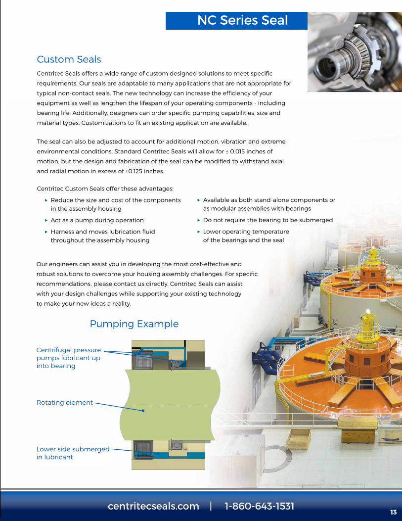
NC Series Seal
Custom SealsCentritec Seals offers a wide range of custom designed solutions to meet specific
requirements. Our seals are adaptable to many applications that are not appropriate for
typical non-contact seals. The new technology can increase the efficiency of your
equipment as well as lengthen the lifespan of your operating components - including
bearing life. Additionally, designers can order specific pumping capabilities, size and
material types. Customizations to fit an existing application are available.
The seal can also be adjusted to account for additional motion, vibration and extreme
environmental conditions. Standard Centritec Seals will allow for ± 0.015 inches of
motion, but the design and fabrication of the seal can be modified to withstand axial
and radial motion in excess of ±0.125 inches.
Centritec Custom Seals offer these advantages:
u Reduce the size and cost of the components in the assembly housing
u Act as a pump during operation
u Harness and moves lubrication fluid throughout the assembly housing
13
Pumping Example
Centrifugal pressure pumps lubricant up into bearing
Rotating element
Lower side submerged in lubricant
u Available as both stand-alone components or as modular assemblies with bearings
u Do not require the bearing to be submerged
u Lower operating temperature of the bearings and the seal
Our engineers can assist you in developing the most cost-effective and
robust solutions to overcome your housing assembly challenges. For specific
recommendations, please contact us directly. Centritec Seals can assist
with your design challenges while supporting your existing technology
to make your new ideas a reality.

Ordering Information
Seal Configuration & DescriptionCentritec Seals are segregated by the specific mounting feature incorporated into the design of the seal.
The standard seal mounting features include:
Press Mount ..........................................................PM
Slip Mount with Integral O-Rings ........SM
Flange Mount with O-Ring ........................FO
Flange Mount Press Fit ...................................FP
Closed at Rest Seals ........................................CR
Part NumberingDigital Numbers 1 2 3 4 5 6 7 8 9 10 11 12 13 14 15 16
Example P M 0 3 1 2 5 0 4 3 7 5 B H S I
Digital Numbers Meaning
1 & 2 Seal Configuration - PM, SM, FO, FP, CR, SS, VM, NC or IF
3 Through 7 Seal ID in inches xx.xxx or in mm xxx.xx
8 Through 12 Seal OD in inches xx.xxx or in mm xxx.xx
13 & 14 Standard seal width (see Chart 1 & 2 below)
15 Material - S (Stainless Steel), C (Carbon Steel), B (Bronze) & P (Polymer)
16 I for Inches or M for Metric
Standard Seal WidthChart 1 - Seal Width (Inches) Chart 2 - Seal Width (mm)
Seal Inside Diameter Standard Seal Width Options Seal Inside
Diameter Standard Seal Width Options
1 TO 3 0.375 0.435 0.500 0.625 0.687 A 25 TO 75 9.5 11.0 13.0 16.0 19.0 L
Over 3 TO 5 0.435 0.500 0.625 0.68 7 0.750 BOver
75 TO 12511.0 13.0 16.0 19.0 22.0 M
Over 5 TO 7 0.500 0.625 0.687 0.750 1.000 COver
125 TO 175 13.0 16.0 19.0 22.0 25.0 N
Over 7 TO 10 0.625 0.687 0.750 1.000 1.250 DOver
175 TO 25016.0 19.0 22.0 25.0 32.0 O
Over 10 TO 15 0.687 0.750 1.000 1.250 1.500 EOver
250 TO 37519.0 22.0 25.0 32.0 38.0 P
Over 15 TO 20 0.750 1.000 1.250 1.500 1.500 FOver
375 TO 50022.0 25.0 32.0 38.0 38.0 Q
G H I J K R S T U V
A broad array of custom seals are available based upon the centrifugal pressure technology, such as:
Split Seals ................................................................SS
Vertical Mounted Seals ................................VM
Custom Seals .......................................................NC
Seal Components................................................ IF
CustomizedSolutions At Centritec Seals, we
understand that not all
customers work within
the same parameters,
which is why we offer
a wide variety of seals
that can be custom
manufactured to meet
your requirements.
Whether a seal needs to
fit into an existing system,
or one of our standard
seal designs does not
meet your specifications,
our team of expert
engineers can assist you
in developing a design
solution that works.
Contact Centritec Seals
for more information
on our custom seal
manufacturing services,
or to request a quote for
your application.
14centritecseals.com | 1-860-643-1531


A Division of the Carlyle Johnson Machine Company
291 Boston Turnpike, Bolton, CT 06043 USA • Phone: 1-860-643-1531 • Fax: 1-860-646-2645
www.centritecseals.com • www.cjmco.com