Embed Size (px)
Citation preview
NIF Ignition
Study Leaders:David Hammer
Lars Bildsten
Contributors Include:Henry AbarbanelJohn Cornwall
Douglas EardleyWill Happer
Stanley Flatt6Russ Hemley
Raymond JeanlozJonathan Katz
Claire MaxDan Meiron
Francis PerkinsMara Prentiss
Roy Schwitters
Consultants:Stephen BodnerJohn Gardner
Jim Hoffer
July 2005
JSR-05-340
Approved for public release; distribution unlimited
JASONThe MITRE Corporation
7515 Colshire DriveMcLean, Virginia 22102-7508
(703) 983-6997
Form ApprovedREPORT DOCUMENTATION PAGE OMB No. 0704-0188
Public reporting burden for this collection of information estimated to average 1 hour per response, including the time for review instructions, searching existng data sources, gatheringand maintaining the data needed, and completing and reviewing the collection of information. Send comments regarding this burden estimate or any other aspect of this collection ofinformation, including suggestions for reducing this burden, to Washington Headquarters Services, Directorate for Information Operations and Reports, 1215 Jefferson Davis Highway,Suite 1204, Arlington, VA 22202-4302, and to the Office of Management and Budget. Paperwork Reduction Project (0704-0188), Washington, DC 20503.
1. AGENCY USE ONLY (Leave blank) 2. REPORT DATE 3. REPORT TYPE AND DATES COVERED
July 20054. TITLE AND SUBTITLE 5. FUNDING NUMBERS
NIF IGNITION
6. AUTHOR(S) 13059022-IN
David Hammer & Lars Bildsten, et al.
7. PERFORMING ORGANIZATION NAME(S) AND ADDRESS(ES) 8. PERFORMING ORGANIZATION REPORT NUMBER
The MITRE CorporationJASON Program Office JSR-05-3407515 Colshire DriveMcLean, Virginia 22102
9. SPONSORING/MONITORING AGENCY NAME(S) AND ADDRESS(ES) 10. SPONSORING/MONITORING
AGENCY REPORT NUMBER
Department of EnergyNational Nuclear Security AdministrationWashington, DC 20585 JSR-05-340
11. SUPPLEMENTARY NOTES
12a. DISTRIBUTION/AVAILABILITY STATEMENT 12b. DISTRIBUTION CODE
Approved for public release
13. ABSTRACT (Maximum 200 words)
JASON was asked by the National Nuclear Security Administration (NNSA) to assess the plan andprospects for achieving inertial confinement fusion (ICF) ignition at the National Ignition Facility (NIF)by 2010, including the use of beryllium targets.
14. SUBJECTTERMS 15. NUMBER OF PAGES
16. PRICE CODE
17. SECURITY CLASSIFICATION 18. SECURITY CLASSIFICATION 19. SECURITY CLASSIFICATION 20. LIMITATION OF ABSTRACTOF REPORT OF THIS PAGE OF ABSTRACT SAR
UNCLASSIFIED UNCLASSIFIED UNCLASSIFIEDStandard Form 298 (Rev. 2-89)
Prescribed byANSI Std. Z39-18298-102
CONTENTS
EXECUTIVE SUMMARY ...................................................................................... 11.1 Response to the Questions in the Charter from NNSA ............................... 11.2 C ritical Findings ........................................................................................ 31.3 Critical Recommendations ......................................................................... 4
2 INTRODUCTION AND SUMMARY ................................................................ 72.1 B ackground ............................................................................................... 72.2 Summary of Assessment and High Level Recommendations ................. 10
2.2.1 Recommendations ....................................................................... 11
3 SCIENTIFIC REPORT ..................................................................................... 153.1 Time Line of an Ignition Experiment ...................................................... 153.2 Hohlraum Physics (Other than LPI) ........................................................ 17
3.2.1 Hohlraum design and development issues ................................... 193.2.2 Discussion of risks and uncertainities .......................................... 21
3.3 Laser Plasma Interaction ......................................................................... 223.3.1 Experimental results to date ......................................................... 233.3.2 LPI mitigation strategies ............................................................. 24
3.4 Capsule physics and Shock Timing, Database ....................................... 263.4.1 One dimensional uncertainties .................................................... 273.4.2 Multi-dimensional Issues ............................................................. 293.4.3 Capsule materials issues ............................................................. 303.4.4 Equations of state issues ............................................................. 323.4.5 Supporting data and experiments ................................................. 323.4.6 R isk m itigation ............................................................................ 33
3.5 Target Fabrication and Cryogenics ........................................................ 343.5.1 Target Fabrication ....................................................................... 343.5.2 C ryogenics ................................................................................. 363.5.3 Risk m itigation ............................................................................ 37
3.6 D iagnostics ............................................................................................. . . 383.6.1 Possible problems and low-yield diagnostics .............................. 403.6.2 Nuclear diagnostics for shots with significant fusion yield ...... 43
3.7 Computing and Software ......................................................................... 443.7.1 Radiation hydrodynamics .......................................................... 443.7.2 Hydrodynamic instabilities ........................................................ 453.7.3 Quantification of uncertainties in fuel capsule design ................. 463.7.4 Hohlraum modeling and laser-plasma interaction ....................... 473.7.5 Software for the comparison of experimental results
w ith sim ulations ......................................................................... 48

3.8 Use of Other Facilities ............................................................................. 493.9 R isk M itigation ......................................................................................... 50
3.9.1 Management Structure/Community Involvement ....................... 513.9.2 Operation at 2-ow: Mitigating the risk of final optics damage .......... 523.9.3 Final O ptics .................................................................................. 53

1 EXECUTIVE SUMMARY
JASON was asked by the National Nuclear Security Administration (NNSA) toassess the plan and prospects for achieving inertial confinement fusion (ICF) ignition at theNational Ignition Facility (NIF) by 2010, including the use of beryllium targets.
JASON was introduced to plans for ignition experiments on the NIF in a meeting onJanuary 13, 2005, in La Jolla CA. Our detailed review of the present ignition plan tookplace at the Lawrence Livermore National Laboratory (LLNL) on March 24-26, 2005. Wewere very impressed during that visit by the accomplishments made by the NiF project andthe planning efforts described by members of the National Ignition Campaign team.Before and after that visit, we corresponded extensively with NIF managers and scientists,and then held a further meeting of the JASON study group in McLean VA on April 17-19,2005.
The NIF ignition program includes a series of experiments at OMEGA (University ofRochester) and Z/ZR (Sandia National Laboratories), as well as analysis, modeling anddiagnostic development prior to 2010. However, in the current plan, further laser targetexperiments at the NIF await project completion. Following completion of the NIFconstruction project in FY 2009, the plan calls for a series of NIF laser-target shots in 2010and beyond, aimed at commissioning target and diagnostic systems and achieving ignition.
We believe that the present choice of beryllium for the fuel capsule shell in theprimary point design target is reasonable on technical grounds and appears to betechnologically feasible given anticipated advances in relevant technologies. This targetdesign is predicted to produce ignition with 1 MJ of input laser energy, but with a small(and highly uncertain) performance margin at this laser energy. Therefore, the currentignition plan, which calls for a maximum laser energy of 1 MJ in FY 2010, eventuallyramping up to a maximum laser energy of 1.8 MJ, carries substantial technical risk forachieving ignition in 2010.
1.1 Response to the Questions in the Charter from NNSA
1. Will the key technologies (target fabrication, cryogenic system, etc.) be in place whenneeded to achieve ignition in 2010?
In our judgment the technologies necessary to support the ignition campaign are likely tobe ready by 2010. The technologies that we investigated included target fabrication, target
preparation, and the associated cryogenic systems. (Our analysis assumes that the NIF'splan for the laser technology will succeed.)
2. Will the key diagnostics be in place when needed, and will they be adequate for the taskof guiding the experimental program through a successful ignition test program by 2010?
We believe that the fall set of diagnostics, as specified by the NIF Program in its March 24-25 presentation to the JASONs, with the possible exception of shock timing, are adequateto provide the critical information needed to diagnose successful ignition campaignexperiments. Unexpected results in the course of the Ignition Campaign may require certainadditional diagnostics for which preliminary designs exist.
3. Does the risk mitigation plan address the highest risk issues, and are the risks at anacceptable level?
Risk mitigation elements currently being pursued by the NIF Program include: 1) a primaryfuel capsule design with backup designs; 2) options for reducing the impact of laser plasmainstabilities; 3) experimental campaigns on OMEGA, LIL (in France), and Z/ZR; 4) theNIF shot sequence, starting in 2009, determined on the basis of risk mitigation, with 30%of the shots held for contingency. In addition, the laser project is developing procedures toidentify and mitigate incipient flaws that develop more rapidly in the final optical elementswhen the laser is operated above 1 MJ.
The important remaining risk factors include scientific questions, issues of complextechnology development, and system integration. We believe that the highest risk issuesare the restriction of the laser energy to 1 MJ in the initial stages of the ignition campaign,deleterious laser-plasma interactions, and implosion asymmetry. These are considered inthe ignition program plan, but we believe that the physics issues need to be moreaggressively addressed via computer simulations, experiments and theoretical studiesbetween now and 2010. Adoption of rigorous procedures for quantifying technicaluncertainties and associated risks is also needed. However, some issues and uncertaintiescannot be addressed fully until the NIF is commissioned.
4. Does the program plan make reasonable use of all ICF program resources andcapabilities, especially OMEGA and Z?
In the case of the OMEGA facility, there is a reasonable plan of laser shots that isintegrated into the NIF program. We found that the plans to use LIL and Z/ZR are not yetadequately developed.
The NIF Ignition Program has scientific and technical risks that demand involvement byexperienced personnel to the greatest extent possible. We are concerned by indications of
2
trends to the contrary. We would like to see greater inclusion of the expertise that exists inICF and related fields at other institutions. We also believe that training new experts in thisarea will be essential to the long-term success of the NIF.
5. What is the prospect for achieving ignition in 2010?
First attempts to achieve ignition on NIF are likely to take place in 2010 - this is animportant and valuable goal that has strongly focused the efforts of the NIF Program. Thescientific and technical challenges in such a complex activity suggest that success in theearly attempts at ignition in 2010, while possible, is unlikely. The Program has identified aseries of tests of the key physical processes and diagnostic instruments that provides areasonable roadmap for progress toward ignition after the initial attempts.
1.2 Critical Findings
The NIF laser commissioning schedule and Ignition Campaign plans call for ignitionexperiments at 1 MJ or less through FY2010. This laser energy is adequate for systemintegration and some of the preliminary experiments that will address physics issues.However, at this incident laser energy, the margins on ignition are thin because unfavorablesmall changes in a few calculated parameters would prevent ignition.
Though raising some new technical challenges, we find that LLNL's development ofa target with a doped beryllium (Be) fuel capsule ablator is sensible. In order to mitigaterisk, the program will carry two fuel capsule point designs, the second one with a CH(plastic) ablator. Experiments on Be as an ablator material that are planned for the nearfuture should address remaining technical issues.
Two physics areas in which uncertainties threaten the achievement of ignition arelaser-plasma interaction and hydrodynamic instabilities such as the Rayleigh-Taylor mode.Both place large demands on computation, and 3D calculations are needed to analyze pointdesigns to the fullest extent possible before the point designs are locked into amanufacturing cycle.
Risk mitigation would be enhanced through a significant increase in thecomputational resources (both capacity and capability) available to the NIF program.Examples of issues that can be addressed by these resources are the effects of laser-plasmainteraction, hydrodynamic instabilities, and quantification of margins and uncertainties infuel capsule yield arising from, for example, uncertainties in material properties andimperfect reproducibility. We view these computational resources as all the more criticalin light of the inability to perform experiments on the NIF during the construction phase.
3
Any large technical project performing ground-breaking science and technology issubject to risks. While NIF has several risk-mitigation program elements in place, we
believe that these can be considerably strengthened by instituting a program ofquantification of margins and uncertainties similar to that being developed on the weaponside of the national laboratories
Standing external oversight machinery for the NIF Program appears to us to belacking. There have been many ad hoc review committees that have evaluated aspects ofthe NIF program over the last decade. Such committees can be useful, but they lack theimpact of a reviewing process that endures, develops a relationship of trust and candor withthe program and can, therefore, help establish priorities and evaluate knowledgeably over aperiod of years the progress that NIF makes toward its goals.
1.3 Critical Recommendations
We recommend that a senior review committee (or committees) be appointed by theLaboratory Director to advise top NIF leadership on allocation of scientific resources andto provide peer review of critical scientific components, such as target and diagnosticdesign. The committee(s) would have technical experts and other individuals drawn frominside and outside LLNL and the NIF program; they should be standing committees andconduct regularly scheduled meetings and reviews that are open to the NIF scientificcommunity where proposals, component designs and the ignition shot plan are discussed,debated and reviewed. The committee(s) could also have technical sub-panels of experts onspecific issues (such as target design, laser-plasma interactions, diagnostics, etc).
We recommend that NIF Program scientists be allocated substantially increasedcomputer resources on world-class computing facilities at LLNL, such as BlueGene/L. Thisis especially important for those carrying out computer simulations of laser-plasmainteractions, hydrodynamic instabilities and integrated target design for risk mitigation andassessment of margins and uncertainties.
We recommend that the non-nuclear (X-ray and optical) diagnostics should be afocus of the early diagnostic development program in order to be able to understand whichphysical processes are responsible for unsuccessful experiments.
We recommend that the NIF program continue its aggressive program to identify andmitigate defects in final optics with a goal of routine operation above 1 MJ for ignitionexperiments as soon as possible in the initial ignition campaign.
We recommend that the NIF Program increase its efforts to resolve the remainingtechnical challenges related to Be fuel capsules, including microstructural and equation ofstate issues, utilizing the best available expertise both inside and outside of LLNL.
4
We recommend an aggressive program of experiments on high energy density laserand Z-pinch facilities, both national and international (to supplement those already plannedfor OMEGA), to improve our understanding of laser-plasma interaction, hydrodynamicinstabilities, and other critical issues, as well as to benchmark computer simulations.
5
2 INTRODUCTION AND SUMMARY
2.1 Background
This JASON review of the inertial confinement fusion (ICF) ignition campaignplanned for the National Ignition Facility (NIF) in 2010 and beyond was requested by theNational Nuclear Security Administration (NNSA) in response to a mandate from Congressin the FY 2005 Senate and House Energy and Water Appropriations Conference Report.The complementary NNSA-sponsored review of the NIF laser construction project that wasalso mandated in that Conference Report is being carried out by a different panel.
In order to carry out this review, the JASON study group received briefings on theNational Ignition Campaign from Lawrence Livermore National Laboratory (LLNL)scientists, engineers and program managers, as well as from other participants in the NIFIgnition Program from Los Alamos National Laboratory (LANL), from the Laboratory forLaser Energetics (LLE) of the University of Rochester, and from Sandia NationalLaboratories (SNL). We had introductory briefings on January 13, 2005, in La Jolla CA,and detailed briefings at LLNL on March 24-25 that were followed by an executive sessionon March 26. Both before and after the March meeting, we corresponded extensively withNIF managers and scientists, who were very accommodating, and we collected manypublications on the key physics, computational and diagnostic issues. The study group heldits final meeting in McLean VA on April 17-19, 2005.
In general, we were very impressed by the remarkable accomplishments of the NIFprogram and by the planning efforts described by members of the National IgnitionCampaign team.
The NIF campaign to achieve inertial confinement fusion ignition and propagatingburn will be a very complex and challenging scientific and technical undertaking. At thepresent time, the anticipated performance of the NIF target is based on computersimulation. While it is true that "experiments conducted at NTS have demonstratedexcellent performance, putting to rest the fundamental feasibility of achieving high gain,"fusion burn in the laboratory has never been achieved. This is the reason for the NIF and itsexperimental ignition campaign.
In our study, we assume that the laser beams meet the requirements set by the targetdesigners for energy balance, spatial smoothness, temporal and spatial power profile andtotal energy. Our main points of focus were: (1) the coupling of the laser power to thetarget, which consists of a hohlraum (a gold or gold alloy cylinder used to convert theincident laser power into x-rays), within which a fuel capsule is contained; (2) theconversion of laser power to x-rays in the hohlraum; and (3) the symmetric implosion ofthe fuel capsule by the x-rays at the appropriate rate and to the required density and
7

temperature to achieve fusion ignition and propagating bum in the fuel capsule. Ourworking definition of "ignition and propagating bum" (often written simply as "achievingignition" in this report) is a fusion energy yield at least equal to the laser energy absorbedin the target.
Even if the laser meets all specifications, there remain many scientific andtechnological issues to address and resolve in the ignition campaign. In addition, effectiveintegration of the laser, support technologies, diagnostic systems and data analysis witheach other and with the computer-simulation-based experimental design program will benecessary for success. Achieving ignition also requires building a capability beyondhardware and software. A large group of highly skilled scientists and engineers who arecommitted to, and engaged in, the ignition program is also essential for success of the NIFignition program. Many of those people are in the program now, of course, but manymore, both experienced scientists and fresh Ph.D's, will be needed in future years. Thisimplies that the NNSA must maintain a broad and strong high energy density physicsprogram in laboratories and universities other than LLNL and LLE.
Because the NIF ignition program involves a large step forward in laser power, targetfabrication requirements, etc., it is expected that areas where there are known scientificuncertainties, such as instabilities associated with laser-plasma-interaction in the hohlraum,will present challenges. Computer simulations suggest that many parameters may have tobe tuned quite precisely to achieve ignition. In addition, there will be issues not at presentanticipated - the notorious "unknown-unknowns" - that are usually encountered when anew experimental regime is entered. Only by doing the experiments can these bediscovered and managed. The large physical scale and high complexity of the ignitionexperimental campaign places it firmly at the forefront of experimental physics.
All of these factors make predicting the number of experiments or the length of timerequired to achieve ignition extremely difficult. Although we have not uncovered anythingthat precludes the achievement of ignition by the end of the first campaign, we believe it is
unlikely that ignition will be achieved that quickly, especially with the laser energy limitedto 1 MJ through 2010, as is the case in the present plan. It is much more likely thatcontinued experiments with laser energies growing to the design value of 1.8 MJ,diagnostic development, and 3D computer simulations benchmarked to experimentalresults will be needed to definitively answer the critically important scientific question forthe NIF from our perspective: "Can a propagating bum be established with a 1.8 MJ laser
in the laboratory?"
The Charter to which we have responded, including its introductory paragraph as wellas the questions to which we responded in the Executive Summary, is as follows:
8
JASON Charter (Dated 1/26/05)
NNSA has formulated an aggressive program to achieve fusion ignitionin the National Ignition Facility in 2010. The key technologicaladvances that enable this schedule are the development of advancedtarget designs and the ability to field ignition targets that may be filledwith deuterium-tritium "in situ.-" In the FY2005 Energy and WaterAppropriations Conference Report, Congress mandated that NNSAconduct a review of the NIF project baseline and the outlook forignition with beryllium fill-tube targets. NNSA will accomplish thereview of the NIF project through a construction project review led byan expert in project management outside of NNSA. JASON is beingasked to review the plan to achieve fusion ignition in 2010, includinguse of beryllium targets. The NIF Project and JASON ignition reviewswill be used by the NNSA laboratory and LLE directors to write aposition paper assessing the prospects for achieving ignition in 2010.This position paper is due to Congress by the end of June. Thepreliminary JASON report is requested by June 1, 2005.
JASON is asked to assess the plan and prospects for achieving ignitionatNIF by 2010. Specific questions include:
1. Will the key technologies (target fabrication, cryogenic system, etc) be in place whenneeded to achieve ignition in 2010?
2. Will the key diagnostics be in place when needed, and will they be adequate for thetask of guiding the experimental program through a successful ignition test programby 2010?
3. Does the risk mitigation plan address the highest risk issues, and are the risks at anacceptable level?
4. Does the program plan make reasonable use of all ICF Program resources andcapabilities, especially OMEGA and Z?
5. What is the prospect for achieving ignition in 2010?
Responses to these questions were presented in the Executive Summary, as were our top-
level findings and recommendations. The remainder of this report provides ourassessment of the NIF Ignition Plan as presented to JASON. Our summary assessment in
Section 2.2 is followed immediately by a collection of the higher-level recommendationsthat are to be found (and justified) in Section 3.
Section 3 contains a description of the scientific and technical issues, our assessmentof the status and prospects for the NIF Ignition Program to deal with those issues, and asubstantial number of recommendations. The findings are not called out as such because
9
such a large fraction of Section 3 consists of findings, but the recommendations areseparately indicated in the text. The specific issues that we discuss are hohlraum physics,laser-plasma interaction (LPI) and fuel capsule implosion. We also discuss computationalneeds for the program, the diagnostics needed to assure that the experimental program canmove forward effectively, and the technologies needed to manufacture targets and deliverthem to the center of the target chamber. Because we believe that risk mitigation must bean important element of the program between now and 2010, we discuss it from a technicalperspective in each of the issues sections. In addition, we have included a separate sectionwith recommendations on peer-review teams and to broaden the community involved in theNIF Ignition Program.
2.2 Summary Assessment and High Level Recommendations
Following their assessment of the impact of FY2005 Energy and Waterappropriations, the NIF management team announced their revised plan to pursue ignitionwith the NIF. This plan is the subject of this JASON study. Among the new features of thisplan are (1) cessation of laser-target experiments of any kind at the NIF until the laser iscomplete in FY09; and (2) use of fuel capsule shells that will be filled with DT fuel througha very tiny fill tube so that cryogenic handling will be required only within the targetchamber.
A very important feature of the present plan is that laser operation will be limited to0.5-1 MJ in the first phase of the ignition experimental campaign in FY20 10 because oflaser commissioning and other system integration activities. Laser commissioning up tothe full 1.8 MJ is to be completed during FY20 11. The lower laser energy is adequate forseveral important elements of the early experimental ignition program, such as systemintegration, commissioning of diagnostics and many of the preliminary experiments thatwill address physics issues. However, with 1 MJ incident laser energy, the margins onachieving ignition with present point design targets are thin because unfavorable smallchanges in a few calculated parameters would prevent ignition.
The present target point-design uses beryllium (Be) with a graded-density copper(Cu) dopant for the fuel capsule shell, with a tiny tube enabling it to be filled withdeuterium and tritium (DT) fusion fuel. This choice is based in part upon recent successesin manufacturing the Be shell and attaching the fill tube. It is also based, in part, on thecomputer-simulation-based prediction that the Be target design will achieve ignition with 1MJ of input laser energy, while the back-up point design based upon a CH (plastic) ablatorwill require perhaps 20% more laser energy to have the same (-10%) performance margin.Therefore, the current ignition plan, which calls for-limiting the laser energy to 1 MJ inFY2010 (compared to the anticipated-maximum laser energy of 1.8 MJ), carriessubstantial technical risk especially in its early phases. Extensive experimental and
10
computational risk-mitigation efforts carried out before the start of the ignition campaignare needed to enable the NIF ignition experiments to address the major issues mosteffectively starting in 2010.
The physics issues that concern us the most in the context of risk-mitigation are laser-plasma interaction in the hohlraum and hydrodynamics issues in the imploding fuelcapsule, such as the Rayleigh-Taylor instability. Both of them place large demands oncomputational capability and capacity, as many 3D calculations are needed to analyze apoint design to the fullest extent possible. Although some risk reduction can beaccomplished by extensive use of 3D computer simulations in conjunction withexperiments on OMEGA (LLE), Z/ZR (SNL), and perhaps elsewhere, some physics issuescannot be addressed until the frll NIF is available.
Therefore, the current ignition plan, which calls for a maximum laser energy of 1 MJin FY 2010, eventually ramping up to a maximum laser energy of 1.8 MJ in 2011, carriessubstantial technical risk for achieving ignition in 2010. However, the program hasidentified a series of tests of key physical processes involving experiments and computersimulations that, together with appropriate diagnostic instruments, provide a roadmap forprogress toward ignition on the NIF after the initial attempts.
2.2.1 Recommendations
The main body of this report (Section 3) contains a discussion of the critical physics,computing, diagnostics and management issues. Embedded therein are recommendations,some of which we highlight here. Each recommendation refers to the sub-section in Section3 from which it was drawn and in which the detailed findings that underlie it also reside.
Much remains to be done between now and the start of the NIF ignition campaign.Tradeoffs will have to be made and hard decisions reached. In addition, the broader ICFcommunity needs to become more actively engaged in the ignition campaign. We havethree recommendations in this regard:
We recommend that one or more technical/scientific advisory committees (TSACs)be appointed by the LLNL Director to advise top NIF leadership on allocation of scientificresources and to provide or oversee peer review of critical program elements. (Section 3.9)
We recommend that the NIF Ignition Program participants organize risk mitigationusing a plan similar to the Quantification of Margins and Uncertainties (QMU)methodology that is being developed in the Stockpile Stewardship Program. This shouldinvolve evaluating the magnitude of both computational and experimental uncertainties andworking to reduce them where possible, and should assess the performance margin in theignition point design capsule at laser energies in the range of 1 to 1.8 MJ. (Section 3.9)
11
We recommend that LLNL create mechanisms (such as the TSACs just mentioned)that enable scientists from outside of the ignition program to contribute to the ignitioncampaign and to fully engage them as part of the team that works toward its potentialsuccess. (Section 3.9)
Part of the modeling and experimental effort must focus on improving the basicunderstanding of the laser plasma interactions (LPI) that occur when the laser light entersthe hohlraum. Improvements in this regard impact hohlraum design, optimization of thelaser beam parameters and configuration, diagnostics and the shot plan.
We recommend allocation of additional computational resources, such as on the 360Tflop Blue Gene/L computer or comparable machines, to enable significant LPI studies. Avigorous theoretical program should be a part of this effort. (Sections 3.3 and 3.7)
We recommend that, in addition to the OMEGA experiments, an aggressivecampaign to improve the level of understanding of LPI in NIF-like plasma and hohlraumconditions be carried out together with French scientists using the LIL laser. (Sections 3.2and 3.3)
We recommend that the community invest time and effort on calculating andmeasuring self-generated magnetic fields in a hohlraum geometry to see if the predictionsof negligible effect are borne out (Section 3.2)
We recommend that a "parts bin" of different hohlraum variations that are predictedin computer simulations to be promising for reducing the deleterious effects of LPI bemanufactured for use at the NIF. (Section 3.2)
We recommend that, as part of a larger, standing risk-mitigation TSAC, a sub-committee of experts on laser-plasma interactions be formed to provide continuing peerreview and advice on the LPI research effort and on LPI issues that are highest-risk to theIgnition Campaign. (Section 3.3)
Delicate control of hydrodynamic instabilities and timing within the imploding fuelcapsule is needed to achieve ignition and a propagating burn. Exercising such controlrequires an assessment of the role of Rayleigh-Taylor and other instabilities and tightcontrol over any initial imperfections in the ablator shell and DT fuel layer.
We recommend that high-resolution 3D simulations be carried out of the behavior ofthe ablator, DT/Be and hot spot interfaces to ascertain the risk of failure to ignite due tohydrodynamic instabilities. Such simulations should eliminate the "hot spot penetrationfactor" as a parameter and enable a more thorough assessment of performance margins andassociated uncertainties. (Sections 3.4 and 3.7)
12
We recommend that experiments be performed on OMEGA that would enableimportant aspects of 3D simulation codes to be validated, such as studies of the fuelcapsule interfaces, the effects of hohlraum asymmetries, etc. The resulting experimentaldatabase would be used extensively to compare with simulations. (Sections 3.7 and 3.8)
We recommend that remaining issues regarding the EOS of DT near 1 Mbar beresolved expeditiously, including undertaking additional experiments, if necessary.Residual issues regarding the EOS and opacity of Be and Cu-doped Be should be thesubject of an experimental campaign. (Section 3.4)
We recommend that an active standing subcommittee of experts be established tocarry out in-depth peer review of the state of modeling and theoretical understanding ofignition fuel capsules in 1, 2 and 3D. (Section 3.4)
Beyond the physics issues, there remain tough technical challenges.
We recommend improved characterization of the microstructures in the finished(polished) sputtered Be capsules and experiments that address the shock-melt of Be (andCu-doped Be alloys) and directly measure the magnitude of the velocity perturbationsarising from microstructural imperfections and anisotropies. (Section 3.4)
We recommend that the development of both the sputtered Be ablator shells with agraded dopant profile and the uniformly doped, machined Be shells be continued until asmall stockpile of acceptable fuel capsule shells can be prepared from one or the other (orboth) methods. (Section 3.5)
We recommend continued consideration of 2-o) operation in the long-term NIFIgnition Plan just as the program is considering Direct Drive in its long-term plan. (Section3.9)
We recommend that the NIF program continue its aggressive program to identify andmitigate defects in final optics with a goal of routine operation above 1 MJ for ignitionexperiments as soon as possible in the initial ignition campaign. (Section 3.9)
Given the challenges inherent in such a large scientific undertaking, we felt it wouldbe better to have a larger diagnostic package than was presented to us. Indeed, our sensewas that the overall effort on diagnostics was largely focused on success and needs to besubstantially boosted to properly diagnose failure modes.
We recommend that the non-nuclear (X-ray and optical) diagnostics should be afocus of the early diagnostic development program in order to understand what physicalprocesses are responsible for tests with low neutron yields. Plans should be developed for ahigh energy X-ray source for X-ray backlighter imaging, for example using an ultra-high
13
intensity, short pulse laser, so that it can be made available as soon as possible after thestart of the ignition campaign. (Section 3.6)
We recommend that the program plan include diagnostics early in the ignitioncampaign that will illuminate hohlraum plasma conditions and important details of theradiation spectrum. (Section 3.6)
We r ecommend that diagnostics be developed that will enable a direct measurementof the sequencing of the four shocks, perhaps through advanced radiographic techniques.(Section 3.4 and 3.6)
We recommend that a hard x-ray emission line-based diagnostic for ablation frontposition based upon dopants in the ablator be evaluated and perhaps tested at Z, where theradiation environment is probably at least as difficult as it will be the NIF. (Section 3.6)
14
3 SCIENTIFIC REPORT
Planning for the ignition phase of the NIF Program is a work-in-progress for severalreasons: 1) construction activities will pace the program for the next several years; 2)actual congressional appropriations will determine what is possible; and 3) significanttechnical uncertainties exist in ignition components, designs and underlying physics. TheNIF laser has clearly been a major engineering achievement so far, for which LLNL and itsstaff can be proud.
The NIF Ignition Plan formally includes three experimental campaigns, the first ofwhich is to be carried out in 2010. The goal of that first campaign is to build up thenecessary facility capability over about 100 tests, beginning with target hohlraumscontaining diagnostic capsules and culminating in an ignition experiment with a DT-filledBe fuel capsule before the end of 2010. While it is not impossible that everything willwork "just so" in the very first ignition attempts, it is unrealistic to expect that to happen.However, that first campaign will be followed by two others in 2011, and each experimentwill move the program toward the goal of achieving fusion ignition.
In this report, we assume that the laser will meet the schedule in the present NIFIgnition Program Plan and that the number of target experiments per year in 2010 andbeyond will be as specified in that plan. Our focus is on the series of events after the laserreaches the entrance to the hohlraum, the uncertain scientific issues and what can be donenow to both mitigate risk and prepare the ICF community for a very challenging scientificexperiment.
We begin this Scientific Report section with a listing of the open scientific issues aswe understand them at the present time, placing them in the context of the time line of anexperiment that is attempting to achieve ignition. Because of the limited time available forthis review, we cannot claim that our list of issues is exhaustive. However, with theconsiderable help of the participants in the program who briefed us and provided follow-upmaterial, we hope we have included the most important ones.
We have recommendations of a technical nature throughout Section 3, some ofwhich we have also presented in abbreviated form in Sections 1 and 2.
3.1 Time Line of an Ignition Experiment
We now present the time line of events in an ignition experiment starting from thearrival of the laser pulse at the laser entrance holes of a hohlraum. We assume that the 192laser beams meet the NIF Project specifications, namely up to 1 MJ in the early NIF
15
ignition campaign, and up to 1.8 MJ later in the campaign, of 3-0) light with the specifiedbeam energy balance, spatial smoothing, focal spot size and power profile. We areconcerned about reproducibility at each step in the time line because it is not yet clear howgood that must be for a successful ignition campaign. However, we are reassured by theapparent reproducibility of the laser power profile in the NIF Early Light experiments.
The time line is presented here in outline form, with issues listed as questions beloweach time line entry. The principal issues are discussed further in subsections addressinghohlraum physics, LPI, and capsule physics. In addition, we discuss technology issues,diagnostics, the importance of computer simulations and the utility of other ICF facilities tothe NIF Ignition Campaign in following subsections. Finally, although we include a risk-mitigation discussion in each of these subsections, we complete Section 3 with a broader-
based discussion of risk mitigation.
1. Laser beams propagate through plasma generated by their interaction with variousmaterials present in the hohlraum, including any gas fill and foam as well as blow-offplasmas from the laser entrance hole (LEH), shine shield, the hohlraum wall or capsuleablator, and hit the walls in the hohlraum.
a. What is an acceptable backscatter percentage?b. What are acceptable levels of hot electron production?c. How much filamentation, beam bending, etc., can occur in the hohlraum before
some poor performance thresholds are reached?d. Will the effects of a-c be reproducible from shot to shot? If not, is the non-
reproducibility directly related to laser performance or target variations or is it aresult of random variations in laser plasma interaction?
e. Will we be able to predict a-d with computer simulations?
2. Hohlraum heats up and produces a symmetric -300 eV black body at peak laser power.
a. Are time dependent asymmetries due to LPI and beam balance acceptable orwell enough understood to control or mitigate them?
b. Does the wall blow off symmetrically and reproducibly?c. Will shine shields achieve their goal without interfering with laser propagation?
3. Fuel capsule is irradiated by the hohlraum x-ray field.
a. Is fuel capsule preheat prevented by the dopant in the ablator?b. Is the energy absorbed by the ablator the same as is predicted in computer
simulations? If not, why?c. Are the ablator and fuel surfaces adequately spherical and smooth?d. Does the ablator have uniform density throughout its volume, without
significant voids?e. Does the first shock melt the doped Be ablator?f. Do we know the doped Be Equation of State (EOS) well enough?
16

g. Is the D-T EOS known and understood well enough?
4. Implosion with a radial convergence ratio of 30:1
a. Do we understand hydrodynamic instabilities well enough to control them?b. Does the implosion velocity reach the required 3-5x10⁷ rca/s?c. Can we reproducibly time the 4 shocks to arrive and coalesce at the right time
and place? (Can we measure the 4th shock timing accurately if required?)d. How reproducible is the implosion process? Is there a suitable metric for this?e. Will the appropriate amount of D-T be blown off the inner surface of the ice
layer to facilitate central hot-spot ignition and propagating burn?f. What fraction of the hot spot cavity will be mixed with cold fuel because of
hydrodynamic instabilities? (Can we measure the extent to which hydrodynamicinstabilities spoil the hot spot cavity?)
5. Ignition of the central hot spot fuel followed by propagating burn in the surrounding fuel
shell
a. Will measurements of the evolution of hydrodynamic instabilities be adequateto validate computer simulations?
b. If the fuel capsule fails to ignite, will the diagnostic suite provide adequateinformation to understand why?
Outside of the time-line, there are other questions that we would like to raise. These are
listed here and discussed extensively in the following sections:
"* Do we need some "non-success-oriented" diagnostics that are not yet in the plan?
"* Has the effect of random parameter changes, within reasonable uncertainty limits,on design calculations been done in multidimensional calculations? Is there enoughcomputer time available to the ICF program to do this?
"* Is it possible that lower performance fuel capsule designs that are less subject toinstabilities should be studied in the early experiments to help validate computersimulation tools?
3.2 Hohlraum Physics
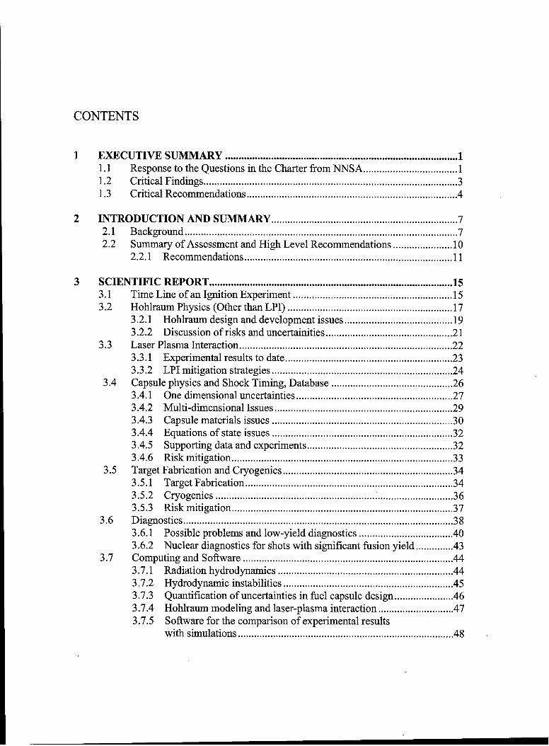
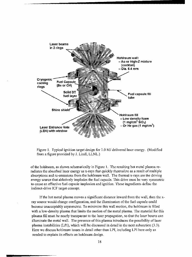
In the simplest picture, an ICF ignition hohlraum is a cylindrical metal can withentrance holes for laser beams in each endcap, and a fusion fuel capsule at its center, asillustrated in Figure 1. At the NIF, ninety-six laser beams are focused through each of thetwo entrance holes, illuminating and heating the metal wall in four rings around the inside
17
Laser beamsin 2 rings
Hohlraum wall:-Au or High-Z mixtureS........(cocktail,)
-Dia. 5.4 mm
Cryogenic e aslcooin Fuel Capsule
rings (Be
"fuel layer Fuel capsule fillfuel layer7.
Shine shiell S i. '' • .Hohlraumn fill
- Low density foam
(1 mglcm3 SiO2)
Laser Entrance Hole . Or He gas (1 mglcm3 )(LEH) with window / •
Figure 1. Typical ignition target design for 1.0 MJ delivered laser energy. (Modifiedfrom a figure provided by J. Lindl, LLNL.)
of the hohlraum, as shown schematically in Figure 1. The resulting hot metal plasma re-radiates the absorbed laser energy as x-rays that quickly thermalize as a result of multipleabsorptions and re-emissions from the hohlraum wall. The thermal x-rays are the drivingenergy source that ablatively implodes the fuel capsule. This drive must be very symmetricto cause an effective fuel capsule implosion and ignition. These ingredients define theindirect-drive ICF target concept.
If the hot metal plasma moves a significant distance inward from the wall, then the x-ray source would change configuration, and the illumination of the fuel capsule couldbecome unacceptably asymmetric. To minimize this wall motion, the hohlraum is filledwith a low-density plasma that limits the motion of the metal plasma. The material for thisplasma fill must be nearly transparent to the laser propagation, so that the laser beams canilluminate the metal wall. The presence of this plasma introduces the possibility of laserplasma instabilities (LPI), which will be discussed in detail in the next subsection (3.3).Here we discuss hohlraum issues in detail other than LPI, including LPI here only asneeded to explain its effects on hohlraum design.
18
3.2.1 Hohlraum design and development issues
The basic task of a hohlraum is to convert incoming laser energy efficiently to auniform thermal x-ray bath for the fuel capsule. To do this efficiently, leakage of x-rayenergy into the wall and escape of x-rays through the laser entrance holes must beminimized. The competing demand on the laser entrance hole is to allow the laser light toenter efficiently and with intensity low enough to avoid deleterious laser-plasma interactioneffects.
Until recently, the metal wall of the hohlraum was planned to be pure gold, and thelow-density plasma fill was to be generated by the incident laser beams from a mixture ofhelium and hydrogen gases. Several design modifications that will enhance the overallefficiency of the hohlraum are being studied at present, largely because of the limitation ofthe laser energy available in the first ignition campaign to 1 MJ instead of 1.8 MJ:
1. Mixtures of materials (known as "cocktails") are being considered for the hohlraumto reduce energy loss through the walls, i.e., to increase the opacity of the walls.This is not a new idea, but it is now more imperative to achieve the 20% energyefficiency gain that might be available, and to face the technological issues thatarise from doing it;
2. The hohlraum length can be decreased to reduce the area through which wall lossescan occur, and this can be done together with laser-entrance hole shields ("shineshields") to reduce direct x-ray energy loss through the laser entrance holes, asillustrated in Figure 1;
3. To reduce the risk that LPI will result in an unacceptable amount of laser energyscattered back out of the hohlraum, larger laser entrance holes (again possiblytogether with shine shields) are being introduced to enable an increase in the laserfocal spot size;
4. Another approach to reducing the risk of LPI is to change the material that willform the hot plasma within the hohlraum, for example, by starting from a foaminstead of a gas fill.
To improve energy efficiency, the cocktail under consideration at present for thehohlraum wall consists of three different metals: gold, uranium, and dysprosium. Theopacity of this mixture is predicted to be higher in the relevant part of the spectrum, and there-emission of thermal x-rays is predicted to be enhanced. It is important to have detailedabsorption and emission spectra for the hohlraum material as manufactured and deliveredto the NIF experiment chamber, including oxygenation. It seems likely that this particular
19
"cocktail" will be feasible to manufacture; if it is not, other effective mixtures of materialsare available.
Several variations in hohlraum design are under evaluation, including the followingfour that were presented in our briefings:
1. "Shine shields" just inside the laser entrance holes (as shown in Figure 1), and alow-density silica-glass foam for low-density plasma generation in place of thehydrogen/helium fill gas in earlier designs;
2. No "shine shields," but a pure helium fill gas (to change the damping expected inone of the stimulated scattering processes discussed in subsection 3.3 relative to thehydrogen/helium mix used in earlier designs);
3. Very low-density helium gas fill plus a thin silica-glass foam liner on the wall thatwill quickly become plasma after the laser pulse begins;
4. Same very low-density helium gas fill, plus a very thin solid silica-glass liner.
Each of the hohlraum variants has some scientific and technical risk. For example,the glass foam may not homogenize quickly, the shine shields may have to be too smalldiameter to provide a significant efficiency improvement, and motion of the plasma fromthe liners in options 3 and 4 may have unacceptable effects on fuel capsule implosionsymmetry.
Further design work should allow the NIF Ignition Program to adopt a single pointhohlraum design in 2-3 years (in FY2008 according to the present plan). With theimportant exceptions of laser beam propagation through, and interaction with, the plasmain the hohlraum, (to be discussed in Section II.C), the radiation-hydrodynamics codesLASNEX and HYDRA are capable of effectively simulating the hohlraum environment,even though mass motions are substantial in current designs.
We recommend that this design process should include peer review by scientistsfrom the broadest possible community to evaluate the remaining physics uncertainties.
We recommend very strongly that a "parts bin" of different hohlraum variations thatappear to be promising in the design process be manufactured to facilitate rapiddeployment in experiments intended to determine the optimal hohlraum configuration onthe NIF. While LLNL scientists have suggested this idea, we are concerned that thesuccess-orientation of the program will leave the parts bin short of possibly usefulhohlraum variations unless this is made a priority.
20
3.2.2. Discussion of risks and uncertainties
If the 1 MJ ignition target designs continue to have positive performance margins incomputer simulations, then the major risks of failure in the hohlraum lie in two questions:1) Will a sufficient fraction of the laser energy propagate to the hohlraum wall through theevolving plasma environment; and 2) Will the location of that laser deposition bepredictable and reproducible? There are three physical elements that pose risk of failure ofthe hohlraum but which cannot be included in integrated target design computer modelingat present: (1) the quality of the incoming laser beam, (2) laser-plasma interaction, and (3)self-generated magnetic fields. The laser may in fact meet the performance requirements todrive the hohlraum effectively to the required radiation temperature. However not all ofthe laser requirements have been met simultaneously, and thus some uncertainty remains.
We recommend that consideration be given to using one quad of the laser todemonstrate, as soon as it is practical to do so, the full energy at 3-w delivered to thedesigner-specified focal spot with all smoothing methods used simultaneously, includingfull aperture continuous phase plates. This could enable adjustments in beam smoothingmethods to be made in a timely and cost-effective manner.
At present, there is little predictive capability for LPI, including the effects that areimportant to energy efficiency and radiation field symmetry. The relevant physicalprocesses are stimulated scattering, and laser filamentation and bending, respectively.Much more will be said about LPI in the next section. Current hohlraum designs areintended to operate below or near the filamentation threshold and in a regime wherestimulated scattering is minimized (less than 10% reflection). However, one cannot beconfident of the actual threshold for serious problems until physics understandingimproves, and possibly not until the NIF experiments begin in FY2010.
The asymmetric density and temperature gradients in a hohlraum cause currents toflow, potentially leading to large (mega-Gauss) magnetic fields. LLNL scientists noted thatthey have done only limited calculations of these magnetic fields because of thecomputational difficulty. However, they believe that the few calculations they have doneindicate that the fields will not change the x-ray generation efficiency or the hohlraumenergy flows by more than a few percent. Such magnetic fields, however, could affect thedynamics of lower-density plasma within the hohlraum, possibly leading to unexpectedlaser beam bending, absorption or scattering of laser light. Because so few calculationshave been performed, and there have been very few measurements of these magnetic fieldswithin a hohlraum geometry, it is difficult to draw the conclusion with any confidence thatthey will have negligible effect.
We recommend, therefore, that the community invest time and effort on bothcalculating and measuring self-generated magnetic fields in a hohlraum geometry to see if
21
the predictions of negligible effect are borne out. Because of the difficulty of suchcalculations and measurements, we recommend that initial experiments and modeling becarried out in simpler geometries that could be used to calibrate the modeling codes.
In summary, significant risks to the NIF ignition campaign remain in hohlraumdesign, but these risks can and should be mitigated by coordinated effort involving theory,simulation and experiments, including work at other research centers.
3.3 Laser Plasma Interaction
The propagation of laser light through low-density plasma to the hohlraum walls canbe affected by laser-plasma interaction (LPI) in the form of several physical processes. Ifnot controlled, these mechanisms can result in significant scatter of the laser light back outof the hohlraum's laser entrance hole, thus reducing the amount of energy that is availableto compress the fuel capsule. Laser-plasma instabilities also produce high-energy("suprathermal") electrons that can preheat the fusion fuel and reduce its compression.Other possible deleterious processes include laser beam filamentation, cross-beam energyexchange, and the deflection of the laser beams from their intended paths.
If the level of light scattered out of the hohlraum's laser entrance hole is reproduciblefrom one laser shot to another, in principle one can increase the input energy of the laser tomake up for the loss. This is a plausible approach because experimental experience showsthat once the reflectivity due to plasma instabilities gets above 20-30%, the fractionalreflectivity does not rise further when the incident laser power is increased. The originalNIF ignition target assumed 1.8 MJ of incident laser light, up to 20% reflection, and anabsorbed laser energy of about 1.45 MJ. The new baseline NIF ignition target that waspresented to JASON assumed 1.0 MJ of incident laser light, 10% reflection due to laserplasma instabilities, and thus 0.9 MJ of absorbed light. If instead the reflection turns out tobe a reproducible 25% (or 35%), then the incident laser light would have to be increased toabout 1.2 MJ (or 1.4 MJ) to yield the same 0.9 MJ of absorbed light. In principle, up to 1.8MJ of laser energy will be available to compensate for higher levels of scatter, but not inthe initial ignition campaign as presented. If the backscatter fraction is not reproduciblefrom shot-to-shot, then increasing the incident laser power will not yield reproduciblehohlraum conditions, and the predictability of ignition will depend upon the sensitivity of agiven fuel capsule design to hohlraum conditions. Therefore, laser backscatteringrepresents a serious potential risk to the goal of achieving ignition in 2010.
Similarly, if the light is reproducibly scattered or deflected to unexpected locationswithin the hohlraum, with sufficient experimental information, one could retune the laser'stemporal and spatial pulse shapes to compensate for asymmetries in x-ray illumination ofthe fuel capsule. However, once again, it would not be possible to compensate for non-
22
reproducible movement of the energy deposition spatial and temporal profiles. While thereis experimental evidence that the level of laser scatter is reproducible under someconditions, the best approach is to design the ignition target to minimize the amount oflight scattered as a result of LPI, and to avoid beam deflection as much as possible.
3.3.1 Experimental results to date
Stimulated Scattering
The two laser-plasma interaction processes that backscatter laser light are calledStimulated Brillouin Scattering (SBS) and Stimulated Raman Scattering (SRS). The firstconverts some of the incident light wave into an acoustic wave and a backscattered lightwave. The second converts incident light into an electron plasma wave and backscatteredlight, plus some suprathermal electrons. Experiments were carried out on the NOVA laserat LLNL in the early to mid 1990's to determine if the backscattering would be adequatelylow in a NIF-type hohlraum to give the go-ahead to the NIF Program. The specificrequirements were that SBS and SRS would separately be less than 5-10% of the incidentlaser energy. One could roughly combine these requirements into the simpler rule that thetotal scattered light energy should be less than 20%. In addition, the energy insuprathermal electrons due to LPI was required to be small enough that it would not affectfuel capsule implosions if suitable design features are included (see subsection 3.4). SomeNOVA results showed high levels of backscatter. However, with full beam smoothing todecrease hot spots in the incident beam, some results from NOVA experiments met theserequirements.
NIF Early Light experiments in Fall 2004, which used half the laser energy but asignificantly larger plasma size than had been used on NOVA, found backscattered lightlevels as high as about 25%. While high backscattering was expected for some of theseexperiments, the level could not be predicted quantitatively. The good news is that thelevel of scatter was reproducible from shot-to-shot and that these results have now beenexplained by sophisticated computer simulations of SBS and SRS. However, the high levelof scattered light is cause for concern since there was not time to fully explore these issuesbefore the series of NIF Early Light target experiments ended.
The possibility that an instability could transfer energy from one ring of laser beamsto another where the rings cross near the laser entrance hole was not investigated in the NIFEarly Light experiments.
Filamentation
Another laser-plasma instability is called "filamentation." In this process, power non-uniformities initially present in the laser beam cause it to undergo self-focusing, in whichthe laser first becomes locally more intense and then the beam spreads significantly.
23
Possible results are that the development of more intense filaments could enhance the
backscattering instabilities, and that the beam might not propagate to the intended area onthe hohlraum wall, thereby interfering with control of hohlraum symmetry.
The NIF Early Light experiments demonstrated that use of beam smoothing(Smoothing by Spectral Dispersion, or SSD) successfully suppressed filamentation and
allowed the laser beam to propagate the required distance to a hohlraum wall. This was animportant positive result from the NIF Early Light experiments.
3.3.2 LPI mitigation strategies
It has been proposed that sufficient beam smoothing will reduce the level of
backscatter as it did filamentation. However, the quantitative impact of beam smooting onplasma instabilities under the conditions of a NIF hohlraum has not been resolved by the
scientific community; there were not enough NIF Early Light experiments that addressed
the backscattering instabilities over the appropriate plasma parameter and length scalerange. Under the NIF Ignition Plan, relevant experiments will have high priority on the
OMEGA laser using improved SSD smoothing. However, they will not be in the NIF laserbeam performance parameter range.
We recommend that, in addition to the OMEGA experiments, an aggressivecampaign to help improve the level of understand of LPI in NIF-like plasma and hohlraum
conditions be carried out in collaboration with French scientists using the LIL laser. (Thislaser is expected to have similar in parameters to the NIF Early Light beams.)
Proposals to re-design the NIF hohlraum for less linear growth of the backscatterinstabilities were listed in subsection 3.2. The hypothesis is that less linear growth willlead to less backscatter as long as the instability is not too strongly driven. Possibletechniques to reduce the linear growth include decreasing the electron density or increasingthe electron temperature in the plasma generated in the hohlraum, and decreasing the laserintensity inside the hohlraum. NIF hohlraum designs that are currently being explored bythe ignition program are aimed at taking advantage of this scaling. Testing these concepts
should and does have high priority in the NIF Ignition Plan, including on OMEGA prior to2010.
Comparison of experimental results with the results from a vibrant theoretical effortand from detailed computer simulations is critical to full understanding of the impact oflaser-plasma instabilities on NIF targets. A major component of risk mitigation for all
deleterious forms of LPI must be increased emphasis on computational modeling togetherwith a vigorous analytic theory program in order to understand the experiments that havebeen carried out in the past and to predict the results of future experiments.
24
We recommend that a strong analytic theory capability be included in the program toinvestigate innovative methods to control the effects of LPI as well as other deleteriousprocesses to be discussed in other sections.
The SRS, SBS and filamentation instabilities were originally modeled using particle-in-cell computer simulation codes that follow detailed motions of both ions and electrons inorder to determine plasma behavior in detail. However, such codes are computationallyintensive and are not able to model large plasma regions or long enough time intervals topredict behavior in NIF-hohlraum-size plasmas. To accomplish that, modem hybrid codessuch as pF3D couple the propagation of the laser beam to nonlinear hydrodynamics of theplasma, with models for the SBS and SRS and at least three types of beam smoothingincluded. A full cross section of the laser entrance hole region with a modest propagationdistance can be modeled in this way. Alternatively, one can simulate the propagation of alaser beam cross section the full distance from the laser entrance hole to the hohlraumwalls. In order to obtain the necessary level of understanding of LPI through comparisonof such computer simulations with experimental results, major investment of computerresources will be required, as will be discussed in subsection 3.7.
We must expect that some uncertainties in the effects of LPI on the NIF IgnitionCampaign will not be fully resolved until tests on the completed laser system can beundertaken. These tests are an important component in the planned NIF IgnitionCampaign. However, a vigorous computer simulation program, together with theexperiments that we have already discussed, could help determine the range of hohlraumplasma conditions that are likely to minimize the consequences of LPI on the NIF.
There have been very significant advances in theoretical and computational modelingof laser-plasma instabilities over the past several years, as well as in the ability to modellaser-plasma interaction experiments. However these models are not yet fully predictive oflaser scattering and filamentation: it is not yet possible to predict quantitatively the effectsof filamentation, SBS, or SRS on a target design that is qualitatively different frompreviously tested designs. Likewise it is difficult to predict the quantitative impact of laserplasma instability mitigation ideas, such as different fill gases, foams, liner materials, orlaser entrance hole shield materials.
We recommend continuing aggressive effort to improve the physics packages forlaser-plasma interaction codes such as pF3D.
We recommend that, as part of a larger standing risk-mitigation advisory committeefor the Associate Director for NIF, a sub-committee of experts on laser-plasma interactionsbe formed to provide continuing in-depth peer review and advice on the LPI research effortand on LPI issues that are highest-risk to the Ignition Campaign. Sorting out purelyhypothetical risks from those needing serious attention will be an important function of this
25
independent panel. Members of this panel will also provide the external connectionscrucial to being able to staff up the NIF laser-plasma team when NIF experiments areimminent.
3.4 Capsule Physics and Shock Timing
All ICF fuel capsules under consideration for the NIF share three major components,the ablator shell, which absorbs the x-rays from the hohlraum and compresses the innercapsule as it blows off radially outward, a layer of deuterium and tritium (DT) ice thatprovides the fuel for the thermonuclear burn, and an inner DT vapor core, which is theresult of the DT vapor equilibrium and depends on the capsule temperature just before atest. The ablator must not only drive the fuel implosion by its vaporization (ablation) andthe familiar "rocket" effect, but it must also shield the DT fuel shell from preheating due tox-rays or hot electrons from the hohlraum. The DT ice layer provides both the cold fuel,which must be kept on a nearly Fermi-degenerate isentrope to provide high yield, and most(estimated to exceed 80%) of the mass for the core "hot spot," where the thermonuclearburn wave initiates. Careful temporal shaping of the x-ray flux onto the capsule is neededto time the shocks that are launched into the capsule so that the dense DT remains on a coolisentrope during compression. A series of four shocks are used that must be timed so thatthey coalesce a few ptm inside the inner ice surface, strongly constraining the laser powerprofile.
There are several factors that control the fuel capsule performance, most of which arefairly well understood. First, ignition will occur only when the hot spot column density, pr,where r is the radius of the hot spot and, p, is its mass density, exceeds 0.2-0.4 grams persquare centimeter (adequate to thermalize the fast alpha particles created by the DT fusionreaction) at an ion temperature of about 10 keV. Reaching these conditions is primarilycontrolled by the implosion velocity, which needs to be at least 3-5xl 07 cm/sec. It is thisimplosion velocity requirement that sets the fuel capsule aspect ratio (radius divided by theshell thickness) and determines the level of hydrodynamic instability that can be tolerated.Second, in order for the compressed DT fuel to support a propagating burn that will yieldan energy gain of the order of 10 relative to the laser energy incident on the hohlraum, thecold fuel must reach a column density of 1.5-3 grams per square centimeter. This canhappen only if the cold DT fuel has remained at a pressure within a small factor of theFermi-degenerate pressure during compression. This is achieved by compressing the fuelby a first shock that sets the initial adiabat and then by a series of shocks with pressureratios generally less than four that do not significantly raise the entropy. Ignition occurswhen the radius of the DT shell is about 30 times smaller than its initial size.
LLNL scientists have an excellent understanding of the relative importance of thevarious design parameters and have spent considerable effort optimizing the fuel capsule
26
performance using 1D calculations. The main variables are the capsule radius (whichdetermines the amount of energy absorbed by the capsule in a fixed hohlraum) and thecapsule thickness (which determines the velocity that the capsule can reach). A criticalconstraint is that the capsule must survive a number of intrinsic hydrodynamic instabilitiesand any asymmetry in the x-ray drive. Indirect drive achieves much of its symmetry byaveraging the radiation flux over the hohlraum wall, as noted in subsection 3.2. Animportant ratio in this regard is the hohlraum radius to the capsule radius, the larger thebetter for more uniformity. On the other hand the efficiency of conversion of laser energyto energy delivered to the ablator decreases as the ratio of the hohlraum wall area to capsulesurface area increases. This leads to fairly straightforward tradeoffs that have led to thecurrent NIF point design. Buried in these tradeoffs are assumptions that have not beenproven, primarily the level of asymmetry and hydrodynamic instability that these capsulescan tolerate.
LLNL is carrying two point design capsules that are similar in overall size and yield,
but differ in the ablator material. One uses a CH (plastic) ablator doped with germanium(Ge) and the other is a beryllium (Be) ablator with a graded-density doping of copper (Cu).The CH ablator capsule has the advantage that there is a great deal more experience in itsmanufacture and characterization, including controlling the surface and material roughness,and in the preparation and characterization of the DT ice layer. It has the disadvantage thatit is predicted to be more susceptible to shorter wavelength hydrodynamic instabilities thanthe graded-density Cu-doped Be target in detailed computer simulations of capsuleimplosions. At the present time, the graded-density Cu-doped Be ablator fuel capsule is thepreferred one.
3.4.1 One dimensional uncertainties
Despite the excellent theoretical understanding at the conceptual level, NIF's success
(i.e., achievement of hot spot ignition followed by a propagating bum) is not assured. Anidentified uncertainty in the 1D "clean" performance is the timing of the shocks. They mustarrive near the inner edge of the ice layer in a tight sequence in order to control the entropyof the DT fuel. By careful timing of the shocks, all but a small faction of the DT fuel can bekept on a constant low adiabat. If the timing is close to being ideal, heat conduction at theinner edge of the DT fuel determines its entropy profile as well as the mass that will be inthe hot spot. If the shock timing is not close, the entropy profile of the inner edge of the
DT fuel is determined by the temporal sequence of the shocks. The density and pr that areachievable depend in detail on the entropy profile in this material. Demonstration that these
processes take place as described is possible experimentally only by an ignition test. Onepossible way to determine the precise shock timing experimentally is to use a target ofslightly greater DT thickness than the designed target and have all shocks coalesce at alocation a few microns beyond the designed target thickness. This technique has beenproposed and used by some of the target designers at LLNL.
27
The material blown off of a surface also leads to density interfaces that can have ahighly perturbed density structure. Passage of a shock through such a perturbed layer maydeposit vorticity and could mix cold fuel into the hot spot to an extent beyond that assumedat present.
Shock timing as an issue involves control of both the shock propagation andcoalescence through timing of the x-ray drive intensity variation with time, which depends,in turn, on the laser power pulse shape. We were told that the relative timing of the shocksmust be accurate to 50 ps for the first three shocks. Their proposed experimental plan usesa Velocity Interferometer for Surfaces of Any Reflectivity (VISAR, see subsection 3.6) tomeasure the shock velocities and shock coalescence time in planar geometry. There remainuncertainties in the VISAR measurements, such as whether pre-heat will have an effect,either from fast electrons or x-rays from the point of laser deposition.
The timing of the fourth shock, which we were told needs to be known to better than100 ps, is especially important and difficult to determine. The ignition plan presented to uscalls for the correct fourth shock timing to be determined empirically by varying the timingof the peak x-ray power over a range of timings in 100 ps steps and using the resultingyield as a figure of merit. The primary difficulty with such an approach is that it assumesthat this is a one dimensional optimization problem and that all other variables are alreadyoptimized. For example, if the failure to achieve ignition is related to hydrodynamicinstabilities, then the correct parameter to vary may be the ablator thickness rather than thelaser power pulse timing in 50 ps increments. Thus, we suspect that getting the final tuningof the shocks will be a much more difficult problem than the current ignition planacknowledges.
The shock timing also leads to rather severe constraints on the time dependentsymmetry. This effect is included in the integrated simulation and should be rolled into theearly time constraints on beam power balance and reproducibility.
Uncertainties in the fuel capsule ablator opacity and in the modeling of radiationtransport affect the amount and rate of ablation, which in turn affect the implosion velocity,shock velocities and the hot spot performance. Thus, the required shock timing andcapsule yield depend strongly on the x-ray spectrum, especially the "hard spectrum" thatcan preheat the ablator material before the first shock arrives. Therefore, obtainingemission and absorption characteristics for the hohlraum and capsule ablator materials,including the harder part of the x-ray spectrum, is very important. The ablation rate andimplosion velocity also depend critically on the fuel capsule materials equations-of-state(EOS), which have significant remaining uncertainties.
28
We recommend that the community of 1D fuel capsule modelers, including people atLANL, LLNL, LLE and NRL, make comparisons of multiple point designs to assess thelevel of code-to-code uncertainty. We also recommend carrying out computer simulationsto determine the sensitivity of the point designs to EOS and opacity uncertainties, whichcan then be used to specify needed improvements to these parameters.
We recommend that a diagnostic be developed that will enable a directmeasurement of the coalescence of the four shocks.
3.4.2 Multi-dimensional issues
The largest uncertainties in capsule performance are related to its response to driveasymmetries (low-order Legendre modes) and hydrodynamic instabilities duringcompression (high spatial frequency modes). The primary source of low mode asymmetryis the geometry of the hohlraum. Shine shields have been proposed to reduce the effect ofthe laser entrance holes, and careful relative timing of intensity changes of the four rings ofbeams is proposed to control the P2 and P4 modes (second and fourth Legendre modes).Higher modes in the drive asymmetry are reduced by the case-to-capsule ratio.Simulations show that these asymmetries can be controlled to the required degree, likelyproviding some design robustness. A major uncertainty lies in the modeling fidelity andwhether the numerical resolution in the LPI code has been adequate to quantify thephysical uncertainties introduced by filamentation and beam spray. Provided that LPIeffects are reproducible and measurable, and that they do not directly impact the capsule, itmay be possible to compensate for them.
Even if the hohlraum delivers a symmetric illumination of the ablating fuel capsulesurface with perfect shock timing, hydrodynamic instabilities during the implosion remaina serious challenge to reaching ignition. The Rayleigh-Taylor (RT) instability acts atseveral stages and plays a critical role in capsule design. At early stages, the RT occurs atthe outer ablation interface, as the less-dense ablating material is accelerating the more-dense shell of cool ablator material and DT ice. It also occurs at the ablator-DT interfaceduring the acceleration, where single mode calculations for the Be capsule point designshow modes as high as 300 are unstable. This is a potentially serious problem for mixingat the DT-Be interface and needs to be further investigated. At later times, decelerationoccurs at the inner DT shell surface as dense DT fuel piles up on the hot, high-pressure, butlow-density hot spot. At the inner and outer surfaces it is expected that ablation of materialaway from the boundary together with decreasing density gradients will stabilize theshortest wavelength modes. This avoidance of an arbitrarily rapid runaway (since theshortest wavelength modes grow the most rapidly with sharp density gradients) allows forthe designer to attempt to control the growth of the instabilities.
At the present time, simulations of the RT instability involve calculations of the lineargrowth factors during an implosion. LLNL "rolls up" all of the RT growth factors into one
29
quantity, which they call the hot spot penetration factor. This is a measure of the extent towhich cold fuel is intermixing with the hot spot material. These growth factors yieldconstraints on the acceptable roughness of the ablator's surface, as well as the DT ice layer.Given an energy absorbed by the capsule (about 140 kJ for a 1 MJ laser input), one cancalculate how large of a hot spot penetration can be tolerated without seriously impingingupon the yield. These calculations are still underway.
We recommend that detailed 3D simulations be carried out of the behavior of theablator, DT/Be and hot spot interfaces to ascertain the level of risk involved. Suchsimulations would supplant the "hot spot penetration factor" as a parameter. Werecommend that experiments be performed on OMEGA that can benchmark the 3D
simulations.
We recommend that reliable central 'hot-spot' imaging diagnostics be implementedearly in the ignition campaigns because instabilities may lead to a very non-uniform hotspot and failure to achieve ignition.
For the 2010 ignition campaign both Be and CH ablator shell fuel capsules will use afill tube to load the DT in place at the NIF chamber center. Numerical simulations indicatethat the target should survive the perturbations introduced by the fill tube and glue joint.The simulations included no other nonuniformities that might couple to this highlynonlinear perturbation. However the modes generated by this perturbation are in a rangethat has relatively low growth factors, and so the impact of the fill tube on the evolution ofhydrodynamic instabilities during capsule implosion is considered to be a moderate risk.
3.4.3 Capsule materials issues
To achieve ignition, it is very important that the implosion of the fuel occurs withspherical symmetry, which will certainly be affected to some degree by how the ablatorshell was fabricated, and by whether it contains a fill tube. For the Be ablator shells, theleading approach at present is to sputter Be onto a mandrel. However, this process leavesvoids within the Be that are potential sources for RT instability. The sputtered Be capsuleswill include graded-density Cu doping that may provide improvements in hydrodynamicstability. An alternative is a machined capsule, constructed as two separate hemispheres.Each Be hemisphere is very uniform, but a non-uniformity is introduced when the twohalves are joined. In machined capsule shells, the Cu dopant must be uniform.
The first shock is designed to melt the Be on the Hugoniot at -2.5 Mbar. However, asthe pressure increases there are velocity nonuniformities induced in the Be ablator due toany voids that may be present. The specifications on the size of tolerable velocityperturbations are severe and constrain the number and size of the voids in the sputtered Be.Target characterization techniques are being developed to measure the microstructure.
30
Smaller grain structures and minimization of voids in the Be structure should reduce thesevelocity nonuniformities.
Studies of the sputtered Be that is used for the fuel capsules show that elastic wavevelocities can vary by 10 percent or more depending on crystal orientation and the presenceof voids. This anisotropy implies a significant asymmetry in the shock velocity. Theporosity and texture have the effect of imposing a ripple on the shock front, and can evenresult in the formation of micro-jets on the -0. 1-10 pm range of the spatial scales of voidsand crystals.
We recommend improved characterization of the microstructures in the finished(polished) sputtered doped Be capsules. We further recommend experiments that addressthe shock-melt of Be and that will directly measure the magnitude of the velocityperturbations arising from microstructural imperfections in shock-melted Be. For example,we encourage the experiments using planned high sensitivity interferometric measurementsof the induced velocity perturbations in planar Be targets.
We recommend that 3D modeling including polycrystalline effects and othermaterials properties should be carried out together with the experiments in order to improvethe ability of the models to simulate conditions in ignition experiments.
We recommend that the Ignition Program retain the machined Be alternative for theBe ablator fuel capsules until the sputtered Be is demonstrated to meet the designrequirements for that shell material. More broadly, on-going projects that examine other,potentially even better ablator materials (e.g., diamond) should be continued.
The response of polycrystalline Be to the x-ray preheat felt near the outer surface ofthe ablator is another issue. The differential expansions during x-ray preheat due to thedifferent grain orientations could cause small velocity perturbations that reverberate untilthey damp out. These velocity perturbations could lead to subsequent RT instability growthat the ablation front and at the Be-DT interface.
Rayleigh-Taylor growth on the inner surface of the DT will depend on both the innersurface roughness and on feedthrough from the DT/Be surface. The presentations wereunclear as to whether the temperature dependence of the roughness of the DT layer belowthe triple point is actually well understood. An empirical relation between the temperatureand the roughness was shown, which, since the vapor pressure is also changing along thiscurve, ties the residual roughness to the density of the gas in the hot spot (one of the criticaldesign parameters).
The ability to measure the interior surface roughness of the DT ice through Be hasbeen solved by the use of x-ray phase contrast imaging, which will be used for CH ablators
31
as well. The DT ice roughness is evidently within the required specifications, but we sawno results showing that the specifications had been met on the need for a very uniformthickness.
3.4.4 Equations of state issues
A fundamental issue is the accuracy with which the equations of state of the criticaltarget materials are known. The EOS of DT figures prominently in the problem of ignition,and warrants examination in view of recent controversies regarding the EOS of hydrogenisotopes. The first shock in the DT sets the initial adiabat, and the subsequent implosion
closely follows an isentrope, during which the material compresses from its initial densityof-0.2 g/cc to -1000 g/cc, to reach ignition conditions.
EOS information for DT is typically obtained from tables such as Sesame or theQuotidian-Equation-of State (QEOS) that were compiled at the national laboratories; theseinvolve fits to experimental (both static and shock compression) data and theoreticalcalculations at the highest densities, with regions of interpolation where information ismissing. In recent years, the Sesame tables have been revised to take into account theimproved accuracy in the density range near 5g/cc made possible by advances in static-compression measurements. At pressures of about 1 Mbar, there have been majordisagreements about the pressure-density relations for hydrogen and deuterium, such as theextent to which there is an anomalous volume of collapse (i.e., 30-50% increase in density).Different types of dynamic experiments (gas-gun, laser-shock, isentropic compression, andshock-loading of pre-compressed samples) appear to be in partial disagreement with eachother, and there is as yet no reliable understanding of how the static and dynamic high-pressure experiments can be related to each other. The possible problems with the DT EOSat -1 Mbar should have second-order effects on the behavior of the system at the more
extreme conditions relevant to ignition; the differences in the Hugoniot at these pressureswill affect the subsequent adiabat followed during further compression. The differences inboth the DT and the Be EOS will likely affect the detailed timing between the stagedshocks.
We recommend that the high-energy-density research community resolve remainingissues regarding the EOS of DT near 1 MB, including undertaking additional experiments,if necessary. We also recommend that residual issues regarding the EOS of graded-densityCu-doped Be be the subject of an experimental campaign.
3.4.5 Supporting data and experiments
Computer simulations depend crucially on accurate measurements of the properties ofvarious materials, as discussed above, and on validation by comparison withmeasurements. For example, there has been a large long-term national commitment tostudying the coupling between radiation and matter under conditions relevant to fusion. For
32
high Z materials, existing codes do not consider every individual absorption and emissionline, but combine transitions into frequency blocks that provide effective opacityinformation that is then incorporated into simulations. Measurements of the emission andabsorption properties of hohlraums excited by lasers are being made on OMEGA and areavailable and can be used to improve the opacity and radiation transport models in thesimulations. The emission and absorption properties of the fuel capsule, including theablator shell and the fuel, may be less well known. As the target becomes compressed,there is a regime in pressure and temperature where even less opacity information isavailable. At extremely high densities, everything becomes a metal and there are reliabletheories and simulations for that regime; however, in regimes with compressions of a fewto - 10, there is not much available information. Molecular Dynamics - Density FunctionalTheory (MD-DFT) simulations using codes such as VASP represent the best currentapproach. (They are used at LANL, Sandia and CEA, and undoubtedly at other places aswell.) This ab initio method has had some good success but also suffers from seriouslimitations.
We recommend measuring the opacities of compressed and heated graded-densityCu-doped Be and hydrogen under conditions similar present in the fuel capsule during thefirst parts of the NIF ignition pulse. Where possible, the measurements should be closelycoupled to simulations.
3.4.6 Risk mitigation
The plan to carry forward two point designs (one involving a CH ablator and theother a Be ablator) is a good one. We believe that 3D simulations with both designs shouldbe carried out with the goal of better understanding the impact of Rayleigh-Taylorinstabilities on the yield. While such simulations are clearly part of the ignition campaign,including many iterations that probe the parameter space limits allowed by the uncertaintieswill contribute to risk reduction.
Risk mitigation should also include investigation of alternative ablator designs thatreduce the risk due to instability of the DT/Be interface or that increase the robustness ofthe designs to uncertainties. Optimum performance capsules do not necessarily minimizerisks. It is important to identify the most serious risks and perhaps consider designs andexperiments that minimize those risks.
The ignition campaign has provided a focus to the NIF Ignition Programs thatexercises all aspects of the effort (the laser, targets, modeling, and diagnostics) and ismoving everyone forward toward a common goal. The specifications on capsule designsare now set internally by LLNL scientists and are taken as hard limits that the NIF programtarget fabricators must meet.
33
We recommend that, as part of a larger standing risk-mitigation advisory committeefor the Associate Director for the NIF, an active standing subcommittee of experts be
established to carry out in-depth peer review of the state of modeling and theoretical
understanding of ignition fuel capsules. We believe that such regular review of the point
designs by the national community will advance the state-of-the-art of fuel capsulemodeling most rapidly and will provide the best input to the experiments once the NIFIgnition campaign begins iii 2010.
3.5 Target Fabrication and Cryogenics
The design of targets for the NIF ignition experiments involves extensive use of
computational tools such as LASNEX to determine potentially optimal combinations ofhohlraum materials, size and shape, fuel capsule materials and shell radii, fabricationtolerances, etc. The full integration of the hohlraum size, shape and materials with the fuel
capsule shell radii and materials, as well as, for example, the DT fuel solid layer thickness,and inner gas density (determined by the ice temperature) are required in the simulations.The net result of a whole series of design calculations is to set limiting specifications on
many parameters, such as the fuel capsule ablator shell diameter and thickness, theroughness of the outer and inner ablator surfaces, the precise DT ice shell geometry,required thickness uniformity and surface roughness (at the solid-vapor boundary), etc. Wewere told that there are about sixty "top level" specifications for the hohlraum/targetassembly that result from this process.
Cryogenics enters the NIF Ignition Program in three interrelated ways: 1) a cryogenicsystem to cool and field the target assembly in the target chamber; 2) precision transfer ofthe DT charge from the on-board reservoir to the interior of the fuel capsule; and 3)cryogenic layering using the concept known as "Beta-layering" to produce the symmetricDT ice layer within the fuel capsule ablator shell.
3.5.1 Target fabrication
Target fabricators have gained considerable experience in previous ICF campaigns,including NOVA and OMEGA laser experiments. The NIF ignition hohlraums are largerthan those used in NOVA experiments and should be easier to fabricate. However, theinclusion of such features as low-density foam or glass liners, internal laser entrance holeshields and the use of special "cocktails" for the hohlraum wall material have not yet beendemonstrated. We believe that there are no critical breakthroughs needed here, and so weexpect rapid progress. The final fully integrated hohlraum-fuel capsule assembly,, complete
with the fill-tube, thermal shimming, DT gas reservoir, and attachments to the cryogenictarget positioner also has not been demonstrated. However, prototypes of the assembly arebeing tested and we can identify no insurmountable problems.
34
The ablator shell material closest to meeting all the required specifications of thepoint design is the CH ablator. (CH implies a homogeneous polymeric material made fromonly carbon and hydrogen atoms - no oxygen or nitrogen.) Even with the complication offour contiguous CH layers having differing compositions of Ge dopant, shells have beenfabricated that meet the stringent outer and inner surface finish specifications. Minor issuesremain, such as isolated material defects and the difficulty in drilling a 5-Rm fill holethrough the wall, but these should require only slight further development.
There are two difficulties associated with the choice of a CH ablator: 1) it requires asmoother DT ice-vapor interface (the so-called 'ice roughness') than a beryllium-ablatorfuel capsule to achieve satisfactory robustness against hydrodynamic instabilities, 2) thepoor thermal conductivity of the CH requires that the hohlraum wall be thermally shimmedto eliminate imprint of hohlraum thermal non-uniformity on the DT ice layer. Without thethermal shimming, the DT ice would not be a uniform spherical shell, thus seeding thehydrodynamic instabilities at long wavelengths.
The current point design target, dubbed "D 1.1," uses a fuel capsule shell with a Beablator. The 160-jim-thick shell wall is composed of five contiguous layers, each having adiffering amount of Cu dopant. Recent improvements in polishing have achieved anoutside surface finish that is close to meeting the NIF requirements.
The manufacturing technique presently preferred for the D1. 1 Be shells is sputteringonto a plastic mandrel shell that is later removed. Sputtering permits the addition of gradedconcentrations of Cu dopant as the shell builds up on the mandrel. Be crystal grains growin a columnar mode, resulting in radially-oriented grains and, unfortunately, manyinterstitial, radially-oriented voids. The voids are particularly problematic because theyrepresent density defects that could seed instabilities during the implosion. We considerthe presence of voids in the Be ablator shell a significant risk to the ignition campaign atpresent.
Fabricating the Be shells by direct machining of hemispherical cavities, bonded withan 1-jim-thin Al braze, is an alternate method that has been developed at LANL. Thestarting material is polycrystalline Be, uniformly doped with a small concentration of Cu.Graded-density dopants are impossible with this technique, but if the same surface finishcan be achieved as with the sputtered material, then the two Be shell approaches arepresently predicted to have equivalent ignition margin. Finally, the subsequent fabricationsteps, fill-hole drilling and fill-tube attachment, are expected to be equivalent for bothapproaches.
We recommend that the development of both the sputtered Be ablator shells with agraded-density dopant profile and the uniformly doped, machined Be shells be continued
35
until a small stockpile of acceptable fuel capsule shells can be prepared from one or theother (or both) methods.
3.5.2 Cryogenics
The cryogenics that must be developed to field the target assemblies has beendrastically simplified by the incorporation of a small fill-tube in the ablator shell. In fact,one of the drivers for the use of a fill-tube is the nearly 2-fold lower cost of the cryogenictarget handling system that is required. Without a fill-tube, a CH-ablator target must befilled with DT by room temperature permeation at high pressure and then cooled inside thepressure cell to below about 30 K before removal. Cold handling and cold 'hand-offs' ofthe target assembly were unavoidable. Be-ablator capsules likewise must be filled at highpressures, either during their fabrication from machined hemispheres or by a drill and plugtechnique. Cold handling could be avoided only if it could be shown that the filled capsulewas strong enough to be transported at room temperature. All of these technical difficultiesare now avoided. By using a fill-tube, cryogenic target handling is not significantly moredifficult than handling (non-ignition) room-temperature target assemblies. The residualtechnical challenge is the transfer of DT from the target handler to the fuel capsule througha fill tube that must be less than 10 jim in diameter.
The use of a fill-tube permits DT storage in a small volume reservoir in the targethandler. This reduces the tritium inventory and hence the radiological risks involved withtritium usage. Because fill-tubes must be very small, there are some potential operationalproblems. The first is the length of time required to fill the fuel capsule with DT,especially in the presence of 3He formed as a product of tritium beta-decay. The 3He doesnot liquefy at temperatures of interest here and hence can act to block the flow as the DTliquefies in the fill-tube at or near the hohlraum wall. Sizeable back-pressures could occurwhich could be compensated by a higher starting pressure and/or inventory in the on-boardD-T reservoir.
The use of beryllium as the ablator material offers substantially more margin in therequired DT ice roughness than does plastic. While this has been known for nearly adecade, the choice of Be in the NIF point design target could not be made until a methodwas found to characterize the quality of the solid DT ice layer inside a shell of this opaquematerial. A successful collaboration between LLNL and LANL has now led to thedevelopment of phase-contrast X-ray imaging of the ice layer. This method is capable ofresolving the surface roughness of the DT ice layers from modes 1 to about 100, i.e., nearlyas sensitively as the "bright-band" optical method used in transparent spherical capsules.The x-rays are only slightly refracted in passing through the target. Hence, the method isless sensitive to optical irregularities in the ice layers such as refraction due to adjacentgrain boundaries. This latter effect causes the bright-band optical method to overestimatethe ice surface roughness, especially at lower temperatures. In fact, recognizing the
36
superiority of the new x-ray method, LLNL states it will implement it even for transparent(CH ablator) shells.
The new characterization method confirms that the inherent roughness spectrum ofbeta-layered DT ice meets the NIF requirement specifications at temperatures above 19.4 Kfor modes above about 10. Moreover, the method confirms that the roughness spectrumdoes not degrade substantially at 18.3 K, the temperature that yields the point design DTvapor density of 0.3 mg/cm3 . However, further research must still be done with the smallerfill tubes to eliminate the large low-mode perturbations blamed on the presence of a 50-gim-diameter fill-tube and "large glue joint" used in that study. If this is accomplished, itwill mean that no enhanced layering methods (such as IR irradiation) need be employedbecause native beta-layering will produce the required smoothness. However, the LLNLlayering technique is very time-consuming. Added to the slow filling time, it remains to beseen whether the particular specification of "no more than 36 hours worth of 3He in thevapor space" can be met.
As noted above, for the proposed CH-ablator shells, thermal shimming of thehohlraum is required. For the direct-drive cryogenic OMEGA fuel capsules, this isaccomplished by employing a spherical "layering sphere" around the capsule that is pulledaway just prior to the shot. The NIF hohlraums are cylinders, not spheres, and couldimprint cylindrical isotherms on the target. By slightly heating the waist of the hohlraumand slightly overcooling the ends, the interior isotherms may be made sufficiently sphericalto adequately reduce the lower modes of the ice layer perturbations to meet therequirements placed by designers on the ignition fuel capsules.
With the Be ablator, thermal shimming could be unnecessary since pure Be is as gooda thermal conductor as pure copper. The outer pure Be layer in a graded doped capsuleshell is rather thick and might establish a good spherical isotherm in the absence ofhohlraum shimming. The entire layer of a uniformly doped Be shell may likewise conductwell enough to reduce substantially the need for hohlraum shimming.
3.5.3 Risk mitigation
We have already recommended carrying forward both sputtered and machinedmanufacturing methods for Be ablator shells until one or the other can meet all necessaryrequirements set by the target designers. We find that the simplification of the necessarycryogenics afforded by the incorporation of a fill-tube adds risk because of 1) theunavoidable perturbations to capsule symmetry produced by the presence of a fill-holethrough the ablator and a fill-tube inserted partially into the ablator, and 2) thedisadvantages noted above of the very small fill tube. It may be possible to produce Beshells that are strong enough to reliably hold the DT charge at room temperature. Such acapsule, filled either by a drill and plug technique or by filling during the joining of
37

hemispheres, would require no cold handling. Of course, it would be necessary to insurethat the steps of high pressure "fill and plug," transport, installation, cool down andlayering all can be carried out within the 36-hour deadline that follows from build up of3He to the point that it would inhibit ignition.
We recommend that the feasibility of high-pressure fill and plug Be ablators bedetermined so that it can serve as a back-up to the use of a fill tube if necessary.
Based upon the presentations, we are concerned that LLNL is not taking maximumadvantage of the experience and expertise of the national laboratories and otherorganizations in the critical area of Be shell production.
We recommend that additional expertise be brought to bear to help solve outstandingBe capsule shell materials science and fabrication issues, including especially the experts atLLNL and LANL.
3.6 Diagnostics
The diagnostics that will be required in the early stages of the NIF ignition campaigndepend upon how difficult achieving ignition proves to be. If easy, it will be unnecessaryto probe the physical state of the target in multiple ways, and success-oriented diagnosticsshould be the focus. However, if the initial ignition shots are expected to have a lowprobability of success without extensive tuning of target and laser parameters, then moreeffort should be devoted to diagnostics that illuminate the reason(s) for failure. "Non-success"-oriented vs. success-oriented diagnostics is just one of many coincidentdichotomies into which NIF diagnostics can be divided, the others being 1) neutron output< 1014 vs. neutron output > 1016, 2) optical and X-ray vs. nuclear, and 3) implosion phasevs. burn phase.
The operational reason for the dichotomy is that if the neutron production is high, X-ray and optical instruments and electronics are not expected to work within or near the NIFtarget chamber. In contrast, nuclear methods require significant neutron production towork.
At the lower laser energies planned for initial NIF operation (0.5-1 MJ), the marginsfor success are narrow and tuning of target parameters and laser power profile must beprecise. We believe that ignition will be difficult, requiring extensive empirical tuning ofparameters as well as large numbers of computer simulation studies of LPI, fuel capsuleand hohlraum hydrodynamics and radiation transport. As such, we believe that a non-success-oriented approach to diagnostic system planning will accelerate progress towardsachieving ignition. This means a focus on optical and x-ray diagnostics that enable a
38
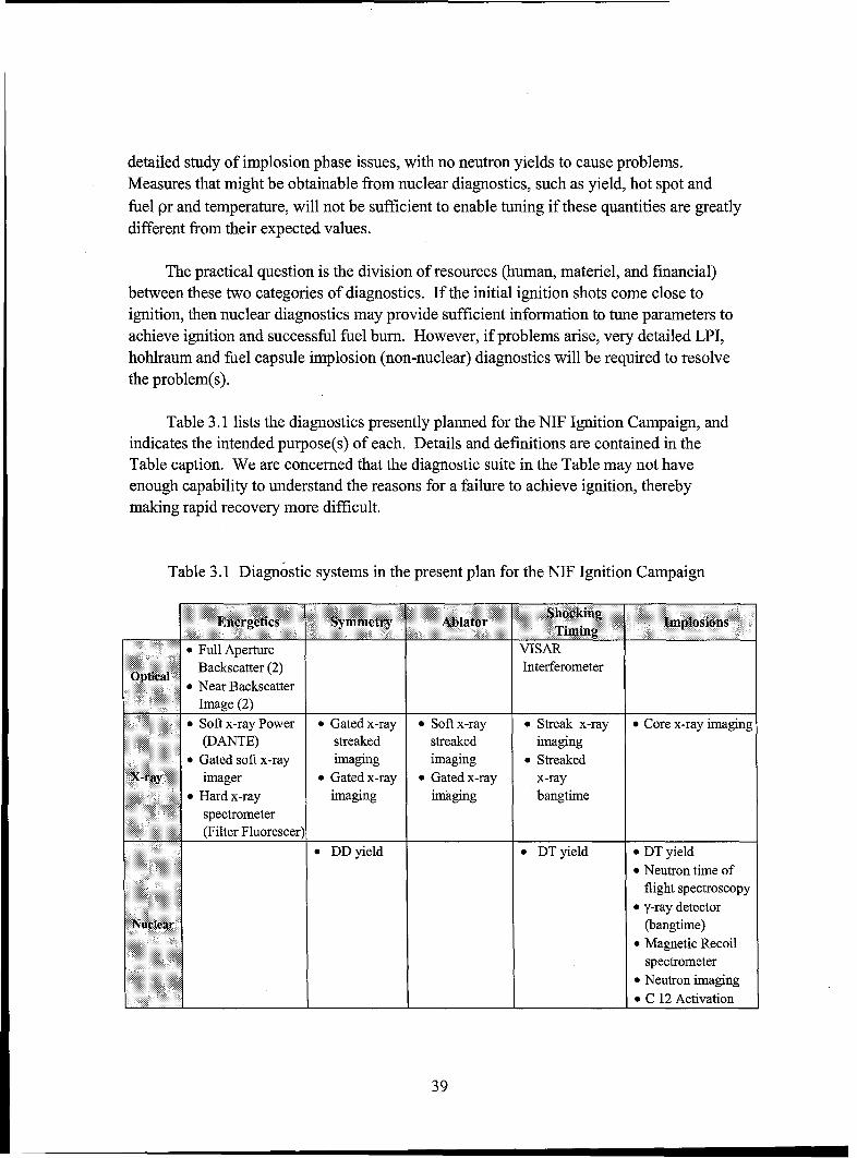
detailed study of implosion phase issues, with no neutron yields to cause problems.Measures that might be obtainable from nuclear diagnostics, such as yield, hot spot andfuel pr and temperature, will not be sufficient to enable tuning if these quantities are greatlydifferent from their expected values.
The practical question is the division of resources (human, materiel, and financial)between these two categories of diagnostics. If the initial ignition shots come close toignition, then nuclear diagnostics may provide sufficient information to tune parameters toachieve ignition and successful fuel burn. However, if problems arise, very detailed LPI,hohlraum and fuel capsule implosion (non-nuclear) diagnostics will be required to resolvethe problem(s).
Table 3.1 lists the diagnostics presently planned for the NIF Ignition Campaign, andindicates the intended purpose(s) of each. Details and definitions are contained in theTable caption. We are concerned that the diagnostic suite in the Table may not haveenough capability to understand the reasons for a failure to achieve ignition, therebymaking rapid recovery more difficult.
Table 3.1 Diagnostic systems in the present plan for the NIF Ignition Campaign
Energetics Symmetry Ablator Shocking Ipoint, ~~~Timing Ipoin
"* Full Aperture VISAROpic Backscatter (2) Interferometer
"* Near BackscatterImage (2)
" Soft x-ray Power 9 Gated x-ray * Soft x-ray * Streak x-ray * Core x-ray imaging(DANTE) streaked streaked imaging
" Gated soft x-ray imaging imaging * StreakedXrAray imager 9 Gated x-ray 9 Gated x-ray x-ray
"* Hard x-ray imaging imaging bangtimespectrometer(Filter Fluorescer)
DD yield * DT yield * DT yield* Neutron time of
flight spectroscopye y-ray detector
Nuclear(bangtime)* Magnetic Recoil
spectrometer* Neutron imaging* C 12 Activation
39
3.6.1 Possible problems and low-yield diagnostics
Here we present an incomplete list of possible difficulties (excluding any failure ofthe laser or the manufactured target to meet specifications) that could cause low neutronyield. These difficulties may result from an incomplete understanding of the fundamentalphysics or from limitations of computational models or resources that might give the targetdesigner confidence of success that is not warranted, examples of which are given for eachdifficulty in parentheses.
1. Reflected energy (LPI-induced SRS, SBS instabilities)2. Preheat of fuel and ablator (LPI-induced fast electrons or hard x-rays)3. An unfavorable distribution of energy in the hohlraum (refraction, scattering, cross
beam coupling, beam filamentation)4. Hohlraum inefficiency (opacity errors, plasma conditions for laser absorption)5. Hohlraum non-black body spectrum (non-LTE effects)6. Hohlraum hydrodynamics (pressure pulse on capsule, wall motion, partial closure
of the laser entrance holes)7. Ablator performance (opacity and/or equation-of-state errors, Be inhomogeneities)8. Instability at the ablator blowoff surface (Rayleigh-Taylor [RT] instabilities)9. Instability at the ablator-fuel interface (RT and Richtmeyer-Meshkov (RM)
instabilities)10.Instability at the fuel-hot spot interface (RT and RM instabilities)11. Shock timing (equation of state errors, uncertainties in various parameters)
Notice that issues we have discussed in previous sections enter in many of the itemsabove. For example, inadequate understanding of LPI contributes to 1-3,11, inadequateunderstanding of equations of state (including opacity) to 4, 5, 6, 7 and 11, inadequacy ofradiation-hydrodynamic calculations to 4-7,11 and inadequate understanding ofhydrodynamic instabilities and limitations of computational resources to 8-11.
Many of the issues listed above have been successfully diagnosed on laser facilities inthe U.S. and abroad, the necessary diagnostics are mature and it should be straightforwardto adapt them to the NIF. (Backscatter diagnostics, for example, were included in NIFEarly Light Experiments.) However, some diagnostics will have to be new, and a few ofthe quantities listed will be a challenge to measure, such as the timing of the fourth shock,to which we will return.
Here we list some of the diagnostic systems followed by the number(s) from thepreceding list of the phenomena and issues they can help illuminate:
A. Full aperture backscatter (1, 2, 11, with spectral diagnostics for SRS)B. Near backscatter imager (1, 11)
40
C. DANTE soft X-ray power and spectrum (4,5,11)D. Time-gated soft X-ray imager (3, 6-11)E. Filter fluorescer hard X-ray spectrometer FFLEX (2, 8-11 with line-emitting
tracers)F. Soft X-ray streaked imager (3, 6-11)G. VISAR interferometer (11, but not in spherical geometry)
There are no nuclear diagnostics on this list because any of these physical processescan manifest themselves as low yield, off-specification bang time (i.e., the moment of peakfusion yield), low fuel temperature and inadequate hot spot and fuel pr, which are thequantities for which the nuclear diagnostics are appropriate. Shock timing (11) appears inall because variations that show up on any diagnostic could be related to a change in shocktiming.
If LPI proves to be a major problem, it will be clear on several of the diagnosticslisted here, but mitigating it will require an understanding of the plasma conditions in thehohlraum. Previously successful diagnostics, such as Thomson scattering and a moredetailed, time dependent x-ray spectrometer than DANTE would be valuable for thispurpose, and there could be others as well.
We recommend that the program plan includes diagnostics that reveal hohlraumplasma conditions and important details of the radiation spectrum in the suite to beavailable early in the ignition campaign.
Because of the inability of these instruments to function (or even survive) in a highradiation environment, it will generally be necessary to employ them in experiments withno neutron yield, as might be expected with laser pulses truncated to include only the firstthree shocks, or possibly with dudded fuel (or no fuel at all because the neutron output ofeven the DD and TT reactions could harm the X-ray or optical instruments). Targetswithout fuel are not good hydrodynamic proxies of complete targets. However, three-shock experiments will have full verisimilitude through the shell compression phase. Thus,full implosion phase and hot spot formation tests, which require the fourth and final shock,may not benefit from X-ray and optical diagnostics. Nevertheless, it is possible thatexperiments can be designed to answer specific questions with specific x-ray or opticaldiagnostics. For example, if ice smoothness is not critical to some other aspect or aspectsof the implosion sequence that is to be studied, H 2 dudding can be used; if ice smoothnessis critical but a significant neutron fluence can be tolerated, T 2 dudding can be used(possibly with a trace of DT to enable use of 14 MeV neutron diagnostics).
The NIF ignition plan calls for a determination of the proper timing of the fourthshock by changing the laser pulse timing in small steps in full ignition tests and optimizingthe yield. This would be done after the timing of the first three shocks has been determined
41

and optimized in planar geometry. Unfortunately, there are several physical processes thatcould reduce yield and prevent ignition, including the possibility of small variations fromone shot to the next in all of the processes 1-10 at the beginning of this section. Thus,varying the laser pulse in small steps with the intention of moving the timing of the fourthshock in small steps may not work.
We recommend that the program seek a more direct measure of the fourth shocktiming, perhaps through advanced radiography, to be discussed shortly.
Among the most critical fuel capsule parameters to know to evaluate an implosion arethe inner and outer radii of each shell (ablator and fuel), their thicknesses, the spread orsmearing of each radius produced by hydrodynamic instability (high spatial frequencymodes) at the surfaces, and deviation from spherical symmetry (low spatial frequencymodes produced by phenomena 3 and 6 plus intrinsic asymmetries such as the fuel capsulefill tube and possible down-coupling of higher mode instabilities). The diagnostics thatcould directly address these issues are X-ray imagers, both streaked and time-gated. Theseare complementary; streaked imagers produce the continuous time-dependence of a one-dimensional slice of image, while time-gated imagers produce a small number (one or afew) of two-dimensional snapshots. X-ray imagers could permit direct determination of theprogress of the implosion (radii vs. time, critical to shock timing), shell thickness (andhence shell adiabats), degree of mixing at interfaces (and hence effects of hydrodynamicinstabilities) and asymmetry. Time-gated images may be the easiest to interpret, and areparticularly suited to studying asymmetry. X-ray backlit images (which naturally providetime-gating if the backlighting pulse is short) of fuel capsules are potentially effective indisclosing and measuring asymmetry. However, we suggest that careful re-analysis of thefoam-ball technique for the NIF parameters needs to be undertaken. Likewise, carefulanalysis of the thin-shell capsules as a measure of asymmetry for NIF parameters should becarried out.
An important issue is the progress of the ablation front in the fuel capsule.Calculations indicate that ablator bum-through must be controlled to 1% accuracy. Atpresent, the accuracy of determining ablator bum-through is estimated to be 10% using thestreaked X-ray imager in slab geometry. Much improvement will be required here, both inaccuracy and in extending the measurement to converging geometry. A possible solution isthe use of hard X-ray line spectroscopy of dopants embedded in the ablator in a very sharp-edged layer, the emission from which will signal the arrival of the ablation front. Theemission lines require a time-resolved detector (unlike the FFLEX) and a narrowbandwidth detection scheme to discriminate against both the thermal radiation and theharder radiation produced by energetic electrons in the hohlraum, The Cu included in Beablators and Ge in CH ablators (each required to reduce preheat) are potential x-ray linesources, or special dopants with emission lines at felicitous energies could be added. (Note
42
that there are significant fabrication issues here because to give a useful time-stamp thedopants must be sharply delimited.)
We recommend that a hard x-ray emission line-based diagnostic for ablation frontposition based upon dopants in the ablator be evaluated and perhaps tested at Z, where theradiation environment is probably at least as difficult as at the NIF.
The Advanced Radiographic Capability, a proposed picosecond time scale, ultra-highintensity laser-based x-ray backlighter imager, could offer a great deal of leverage inattacking many of these implosion issues (especially 7-11). An X-ray energy of 17 keVhas been proposed, an energy where the cold material optical depth of a 25ýtm goldhohlraum wall is 4-5. Therefore, the backlighter imager would require the use of Bewindows covered with about 5 Rm of gold, at the price of some potential asymmetry afterthe thinner layer of gold burns through.
We recommend that plans be developed for a high energy X ray source forbacklighter imaging using an ultra-high intensity laser pulse so that it can be madeavailable as soon as possible after the start of the ignition campaign.
3.6.2. Nuclear diagnostics for shots with significant fusion yield
There are a number of nuclear-based diagnostics that can be used to determine thefuel conditions in which nuclear yield is produced. The burning region is characterized byseveral quantities:
13. pr (hot spot and fuel shell)14. Tion (ion temperature, both in the hot spot and in the fuel shell)15. Total yield16. "bang time"17. Symmetry (both of the hot spot and the fuel shell)18. Te (electron temperature, both in the hot spot and the fuel shell)
Here we list some of the diagnostics, followed by (in parentheses) the parameters fromthe preceding list that they best diagnose:
H. Neutron Reaction History (nRHS) (15, 16)I. Gamma-ray Reaction History (yRHS) using gas Cerenkov detector (15, 16)J. (n,p) scattering in plastic, followed by diode detection (Protex) (15)K. Radiochemical activation (Cu or 12C(n,2n)Q1C) (13, 15)L. Neutron imaging (unscattered and scattered) (17)M. Magnetic recoil spectrometry (MRS) of protons from (n,p) reactions (14)
43
N. Neutron time-of-flight (nTOF) using CVD diamond detectors (13-16)0. High energy X-ray imager (HEXI) (13,17,18)
Most, but not all, of these diagnostics are mature. Even though not all are likely to bedeployed in 2010, they will provide a powerful suite of diagnostics for assessing bumconditions when they are needed.
However, if ignition does not occur it will probably not be possible to determine howand why a shot failed from nuclear diagnostics alone because, as noted above, many failuremodes may produce similar nuclear characteristics. These are really late-time diagnostics,and are not specific in diagnosing the early-time behavior of the target, the diagnosis ofwhich will probably be critical to understanding a failure to ignite.
We recommend that, on balance, the non-nuclear (X ray and optical) diagnosticsshould be the focus of the diagnostic development program for early ignition campaignexperiments in order to understand what physical processes are responsible for low neutronyields.
3.7 Computing and Software
Computation plays an essential role in the NIF program. The simulation of thecomplex processes that ensue during a NIF shot requires state-of-the-art capability. In thissection we review the role of computation in modeling the radiation hydrodynamics thatdrive the capsule implosion as well as the complex laser-plasma interactions that take placein the hohlraum to generate the indirect x-ray drive. We also discuss briefly the role ofcomputation in the analysis of the data that will be generated by the many experiments thatwill be carried out in support of the NIF Ignition Campaign.
3.7.1 Radiation hydrodynamics
The NIF program makes primary use of two radiation hydrodynamics codes to designand analyze the performance of hohlraums and capsules for ICF implosions. The first,LASNEX, is a two-dimensional legacy code based on a Lagrangian framework with amesh remapping capability. The second, HYDRA, developed partly under the aegis of theASC program is a fully three dimensional radiation hydrodynamics code based on anArbitrary Lagrangian-Eulerian (ALE) framework. It includes second order differencingand monotone shock capturing algorithms. It represents a state-of-the-art capability inradiation hydrodynamics simulation. Both codes have been extensively compared withexperiments relevant to the ICF problem. Both codes also include most of the relevantphysics phenomena needed to model the NIF target. An important exception is that neithercode currently has the capability to model laser plasma interaction (LPI) instabilities in a
44
hohlraum. This is treated in the rad-hydro codes by decrementing the laser energyavailable to the hohlraum. LPI is modeled in detail using other codes, to be discussed insubsection 3.7.4.
Numerous physics packages and post processing diagnostics packages are available inboth LASNEX and HYDRA with modules that provide a variety of models for the mostuncertain physics such as radiation transport, EOS, and opacity. This multiplicity of modelscan be used to assess the uncertainties introduced by the approximations. In addition,HYDRA is a parallel code and is capable of running on the massively parallel computersavailable on Livermore's ASC class computing facilities, which can provide tens ofTeraflops of computational capability.
Integrated calculations including the hohlraum and capsule, plus the possibility ofshine shields in front of the laser entrance windows, provide the most self-consistentsimulations of all the phenomena. An important aspect of the target performance is thecontrol of asymmetries arising from the refraction of the laser beams by density gradientsin the complex plasma that results from the laser-hohlraum interaction. It is important,therefore, that adequate resolution of these phenomena be used and that a carefulassessment of the consequences of numerical modeling errors be made. As discussedbelow, there are indications that it would be of benefit to the program to carry out moresimulations in both a capability and capacity mode. The amount of computational resourcesdedicated to the NIF project, therefore, particularly in support of the three dimensionalsimulations with HYDRA, may have to be substantially increased.
3.7.2 Hydrodynamic instabilities
A critical issue affecting the ignition of the ICF capsule is the control ofhydrodynamic instabilities. Because computer limitations restrict the number of modes thatcan be simulated in the capsule in fully integrated (that is capsule plus hohlraum) 3Dsimulations, the assessment of the impact of Rayleigh-Taylor and Richtmyer-Meshkovinstabilities in the capsule is done in a different way. Instability growth is taken from theresults of single mode simulations performed at initial amplitudes sufficiently low that theyremain linear throughout the simulation. Growth factors for each mode introduced by eachsource (outer surface perturbations, inner surface ice roughness, internal layernonuniformities, etc.) are then determined. The amplitude of each mode is then found byapplying the growth factor to an expected initial amplitude of each mode. The modalamplitudes in this multi-mode setting are summed in quadrature. This is a valid procedureshould these modes remain in the linear regime, and significant effort has gone intodesigning capsules that are optimized in this regard. Corrections for possible evolution ofthe modes into a weakly nonlinear regime are accounted for by using a weakly nonlinearsaturation model developed at LLNL. The result is used to determine the penetrationdistance of the cold surrounding fuel into the hot spot. This, in turn, serves as a figure ofmerit for gain reduction. The basis of this approach is that the growth of the (fastest
45
growing) short wavelength modes are strongly affected and stabilized by the ablationprocess.
The validity of the application of linear theory is assessed by using a more limitednumber of multimode simulations of capsule performance where the full nonlinearinteractions and yield degradation are simulated; such consistency checks were not shownduring this review and, in some cases, have yet to be performed for the exact fuel capsuledesigns under consideration for the NIF Ignition Campaign. We view such multimodecalculations using the current target designs as essential to verification of the model used inthe integrated ignition calculations.
We recommend that experiments be performed on OMEGA to assess how the Be/DT
interface behaves in drive conditions that are relevant to NIF ignition experiments and thatthe resulting experimental database be used extensively to compare with simulations.
A related issue is the modeling of fluid mixing during the implosion process arising,for example, from local Kelvin-Helmholtz instabilities. These are important in the contextof capsule implosions because they can result in mode mixing, i.e., low spatial frequencymodes produced by mixing of high spatial frequency modes. The result would be faster-moving, larger scale bubbles and spikes that can penetrate deeper into the hot spot in thelate stages of the implosion. NIF capsules are optimized to minimize such mixing but it iswell known that present day codes can artificially damp such instabilities if the simulationsare not adequately resolved. Some very preliminary results along this line were presentedby LANL scientists, who have also used LASNEX to model NIF implosions. The LANLwork examined the effects on capsule implosion when subgrid scales were modeled. Inview of the limited ability of most simulation codes to adequately model such mixingprocesses, it would be important in future work to understand the role of this mixing and
whether it has any impact on the location of the fuel capsule ignition "cliff."
3.7.3 Quantification of uncertainties in fuel capsule design
Scientists at LLNL have carried out many studies of the effects of variousasymmetries and capsule nonuniformities on capsule gain and have developed anunderstanding of the relative importance of the various factors. They have not developed anequivalent understanding of the effects of modeling uncertainties (both numerical andphysical). Extensive comparisons to experiment have provided considerable confidence inthe simulation capabilities, but quantitative estimates of the uncertainties are lacking. As a
result, there remains uncertainty in the gain achieved in purely 1D (radial) calculations. It isthe pure radial flow that provides the base state that is then perturbed in order to assessuncertainties arising from instability growth.
We are also concerned that a quantitative understanding of the errors associated withthe binning of the opacities to treat radiation transport is lacking. Uncertainties in the
46
radiation modeling, EOS, and opacities can also affect the growth of Rayleigh-Taylorinstabilities. A quantitative assessment of the uncertainties from these effects is currentlylacking but work in this direction is in progress.
Finally, a more quantitative assessment is needed of the effect of using the weaklynonlinear quadrature roll-up of single modes discussed above as a means of determiningyield degradation. This will require the use of highly resolved 3D simulations with realisticinitial perturbations near the ignition cliff since the location of the ignition cliff will besensitive to these uncertainties and this, in turn, can be a critical source of risk for theproject. In addition, more highly resolved 3D multimode simulations may be required toassess the behavior of the DT/Be interface for the Be fuel capsules where large growthfactors at the higher mode numbers are expected. The LLNL scientists recognize thesedifficulties.
We recommend substantially increased computational resources to address the aboveissues. In particular, such capacity-mode calculations can help provide a thoroughassessment of performance margins and uncertainties.
While very highly resolved simulations have been carried out in two dimensions (byLLNL, NRL and other groups), simulations of equivalent resolution in three dimensionswill require considerable ASC-class resources (in addition to appropriate staffing). We seethe need for both capacity-mode calculations (large numbers of lower resolution runs toassess uncertainties and margins) as well as capability mode calculations (to provideconfidence in the lower resolution assessments).
3.7.4 Hohlraum modeling and laser-plasma interactions
In addition to the target design and analysis codes, considerable effort has gone intothe development of separate codes to investigate laser plasma interaction (LPI) issues in thehohlraum. In subsection 3.3.2, we discussed the computational methods used for simulatingLPI. To summarize, the present state-of-the-art code, pF3D, can study larger spatial scalesand timescales approaching those in an actual NIF hohlraum. This code uses a model thatcouples the propagation of the laser beam to nonlinear hydrodynamics of the plasma,including models for SBS and SRS backscatter that come from hybrid simulation codes andexperimental data, and also including beam smoothing. Calculations of LPI in a NIF-scalehohlraum with pF3D require substantial computational resources (typically tens of hours ofruntime on several hundred processors of an ASC level computer).
From the briefings received, it is our view that it has been difficult for the laser-plasma interaction groups at LLNL and LANL to gain access to this scale of computationalresources on a routine basis. Yet computations such as these serve as a very significantrisk-mitigation strategy for the NIF Ignition Campaign. In particular, full pF3D runs will
47
be needed more frequently than they have in the past, and these runs will have to coverlarger volumes and longer times than they have in the past.
We recommend allocation of additional computational resources, such as the 360Tflop Blue Gene/L computer or comparable machines, to risk-mitigation studies ofuncertainties related to laser-plasma instabilities. We view this as a very important riskmitigation strategy for the NIF Program.
An additional need for large-scale simulations could potentially come from studies ofmagnetic field generation in the hohlraum, which was introduced in subsection 3.2.2.LASNEX simulations in 2D showed that magnetic fields generated near the laser entranceholes could have significant effects on the plasma thermal conductivity, which, in turn,affects the temperature, velocity and density profiles. The 3D code, HYDRA, has a morelimited magnetic field capability than LASNEX. However, temperature and densitygradients in the vicinity of the laser spots and possibly near the fill tube are a potentialsource of magnetic fields, which are inherently 3D. The major issue in simulating thisphenomenon is providing sufficient resolution to resolve the density and temperaturegradients and the magnetic field generating source terms as well as the field itself. Thesesimulations will undoubtedly also require considerable computational resources.
3.7.5. Software for the comparison of experimental results with simulations
Each NIF diagnostic instrument is to be delivered with a complete data-analysissoftware suite. We were told that for the NIF Early Light experiments, this data analysissoftware worked well and produced results soon after the target shot was complete.However when ignition-campaign experiments begin at NIF, target designers andexperimenters will need other software tools to understand quickly whether the outputs ofthe diagnostic instrument software agree with the predictions of hydrodynamics models andof laser-plasma interaction codes. This requires a class of "interface" software that uses theoutput of hydro codes or laser-plasma interaction codes to compute what the expecteddiagnostics signatures should be for a specific target design.
It is our understanding that much of this interface software exists today and is used bytarget designers and laser-plasma interaction physicists to compare experiments withpredictions. However, to assimilate numerous NIF target shot results rapidly and to planfor modifications in future shots, the existing interface software should be standardized,and optimized both for computational efficiency and ease of use by many potential users.
We recommend that standardized and optimized interface software developmentbegin very soon.
48
3.8 Use of Other Facilities
The OMEGA laser system was designed and optimized for direct-drive illumination,not for the study of NIF indirect-drive targets. However, because of the significant laserenergy available, up to 30 kJ, and the flexibility inherent in this laser system, OMEGA hasplayed an important role in support of the NIF program. That role will necessarily increasenow that NIF laser-target experiments are halted until the NIF Project completion in mid-FY2009. In each of the major elements of the ignition campaign, OMEGA experimentswill help LLNL scientists make key decisions.
OMEGA experiments on critical issues include campaigns to evaluate hohlraumcocktails, decide between the use of gas or foams or liners in the hohlraum, evaluate Be asan ablator material, and evaluate ways of reducing laser-plasma instabilities via beamsmoothing in hohlraum geometry. OMEGA will also be used to evaluate the cross-beaminteractions between laser beams near the entrance holes, and their interaction with plasmablowoff from the edge of the entrance holes.
An important role for OMEGA will be used to activate and validate a variety of newdiagnostics that could be used for ablator burn-through, shock timing, and fill tubeperturbations. This laser could also be used for exploratory studies of self-generatedmagnetic fields and related diagnostics.
Some of these physics topics will require a new set of phase plates that are optimizedfor x-ray drive. The final design of these phase plates will be completed soon, and theywill be installed on OMEGA in 2007. Future x-ray drive experiments on OMEGA willhave the option of using the same beam smoothing as will be available on the NIF, orsignificantly more smoothing for comparison studies.
We recommend that experiments be designed for OMEGA that would enableimportant aspects of 3D simulation codes to be validated, such as studies of the fuelcapsule interfaces, the effects of hohlraum asymmetries, etc.
The LIL laser facility in France is expected to begin laser-target experiments in 2006.This facility will produce laser energy and have a beam geometry similar to what was usedin the NIF Early Light experiments. In other words, the laser beams will all be incident onthe target from one direction, as compared to OMEGA where the laser beams are incidentfrom all directions. LLNL is planning to take part in these French experiments on LIL.
We recommend that LLNL scientists propose detailed experiments to address issuesrelated to LPI physics and other relevant physics issues on this facility because of theunique and important contributions that are possible with the LIL laser configuration.
49
Plans by the NIF Ignition Program to make use of U.S. high energy density facilitiesother than OMEGA do not appear to be well developed. The Z facility can produce 1-2 MJof x-rays over 4-10 ns. Several types of experiments are possible with this source thatmight provide important contributions to the understanding of the NIF targets. Theseinclude EOS, melt morphology and radiation opacity information, on Be and high Zcocktails, at both high and low densities. The Nike KrF laser has the unique capability ofproducing ultra-uniform laser illumination over a spot size of nearly a millimeter. With thiscapability for uniform pressure generation in a simple geometry, Nike has been used tomeasure the DT EOS up to 1.5 Mbar. Nike could also be used to make similarmeasurements on Be, and also to make x-ray opacity measurements on compressed Be.
We recommend that LLNL scientists work with their counterparts at Sandia andNRL to determine which of the two facilities, Z/ZR or Nike, can best be used for theaccurate determination of fundamental information on materials, and then appropriateexperiments should be carried out.
3.9 Risk Mitigation
Any large technical project carrying forward ground-breaking science andtechnology, as is certainly the case with the NIF Ignition Program, is subject to scientificand technical risks. We have discussed many of them in the preceding sections, andoffered specific recommendations to address some of them. Here we would like to makesome suggestions as to how the program might deal with risk in a more systematic way.Because of a general orientation toward success in the NIF Ignition Program the strategiesfor identifying and mitigating risks are not articulated at the level of detail that we feel isappropriate.
In the limited time available for our study, we cannot expect to have identified theimportant physics issues more effectively than can the scientists within the program. Assuch, we believe that a detailed and prudent risk mitigation plan must be their product, notours. Therefore, while we suggest a particular strategy for doing this here, our point is thata systematic approach to risk mitigation should be put in place. The purpose of such astrategy between now and the start of the NIF Ignition Campaign is to maximize thelikelihood that the scientific issues associated with achieving ignition will be answered
within a reasonable length of time (1-3 years) after the start of ignition experiments.
We recommend that the NIF Ignition Program participants organize risk mitigationusing a plan similar to the Quantification of Margins and Uncertainties (QMU)methodology that is being developed on the weapon side of the Stockpile Stewardship plan.This tool should involve evaluating the risks associated with both computational and
50

experimental uncertainties, and should particularly assess uncertainties and performancemargins associated with laser energies in the range of 1 to 1.8 MJ.
The risk mitigation strategy should both identify and quantify risks and enable agileprogram response when the risks associated with particular uncertainties are found to beparticularly important and are amenable to mitigation, for example by experiments onOMEGA, Z/ZR, Nike or LIL, or by an aggressive and detailed computational study.
JASON was asked to focus on the early phases of the ignition campaign. Ourrecommendations, however, are intended to address risk mitigation up to the initial ignitioncampaign in 2010 as well as beyond. Long-term risk mitigation strategies should includeplanning for such options as direct drive and using the laser light in the green (2-o)) insteadof in the blue (3-co), where considerably more laser energy could be available at thehohlraum. We briefly discuss the latter possibility at the end of this section.
Probably the single most important risk mitigation activity in the current program plan is tobring the laser energy delivered to the target up to the ultimate 1.8 MJ at 3-o as early aspossible in the ignition campaign. Therefore, although the laser was specified as "a given"for our study, we conclude this section with some information on the 3-o) opticsdevelopment effort.
3.9.1 Management structure/community involvement
NIF management is quite properly focused on completing major construction items inpreparation for the ignition studies to follow. The management team is strong and theyappear to be guiding the construction phase toward a successful completion within thecomplex set of constraints under which they must perform.
Management issues will change as NIF transitions from the construction projectphase to executing the ignition program. Success in the NIF ignition program requiresmanagement of critical scientific resources such as computer time, access to specialtechnical facilities and allocation of laser shots, in addition to the traditional projectresources of time, money and scope. The very high value of individual laser shots demandsextraordinary care with component designs, simulations and system-integration of lasercontrol, hohlraums, fuel capsules and diagnostics.
We recommend that one or more technical/scientific advisory committees (TSACs)should be appointed by the LLNL Director to advise top NIF leadership on allocation ofscientific resources and to provide peer review of critical program elements, such as targetdesign and development of diagnostic systems. The TSAC(s) should be standingcommittees comprising technical experts and other individuals drawn broadly from insideand outside LLNL and the NIF Ignition Program. TSAC(s) should conduct regularly
51
scheduled meetings and reviews that are open to the NIF scientific community whereproposals, component designs and the ignition shot plan are discussed, debated and
reviewed.
We also believe that risk mitigation should include efforts to enlarge the communitythat is committed to the success of the NIF ignition campaign.
We recommend that LLNL create mechanisms (such as the advisory committees justmentioned) that enable the broadest possible community to contribute to the ignitioncampaign and be part of the team that works toward its potential success. If LLNLsucceeds at getting participation from universities and other laboratories, it will be betterpositioned to address the new physics questions that are bound to arise during the ignition
campaign.
3.9.2 Operation at 2-co: Mitigating the risk of final optics damage
The baseline NIF Ignition Program calls for tripling the fundamental laser frequency
in the infrared to the ultraviolet using non-linear materials, and delivering that so-called "3-
(o" light to the target. In favor of the 3-cp operation (vs 2-(o) is that higher hohlraum
temperatures are predicted to be reached before LPI will cause unacceptable laser
backscatter and hot electron generation; this, in turn, means that less laser energy is neededfor ignition. However, this strategy introduces risks associated with a lower damagethreshold for the final optics, the existence of which has long been known and which theNIF project is addressing (see next sub-section). One possible risk-mitigation strategy is to
switch laser operation from the baseline 3-rn mode to operation at 2-o) (visible green light).Changing from tripling to doubling, in itself, carries little or no risk, since the technologyand equipment is very nearly the same. Roughly speaking, the threshold fluence for
damage of optical components by 2-o) laser light is two or three times larger than that for3-on light, meaning that the total laser energy output could be increased by this factor for
the same level of optics damage. Target designs for 2-(r light that are comparable in
performance margin to the point design for 3-ro light at 1.8 MJ, but with a hohlraumtemperature reduced from 300 eV to 275 eV to account for the reduced LPI threshold, arepredicted to require over 3 MJ of 2-on light. However, that energy at 2-on (over 3 MJ,
instead of 1.8 MJ at 3-(r) can be achieved by the NIF laser.
We recommend continued consideration of 2-rn operation in the long-term NIFIgnition Plan just as the program is considering Direct Drive in its long-term operationalplan.
52
3.9.3 Final Optics
We were told that damage of laser optical elements is not an issue in the NIF laserexcept for optical elements that are subject to a high fluence of frequency-tripled (3-rn)light, i.e., the light that is to be delivered to the target. Frequency-tripling occurs justbefore the light is delivered to the target chamber and so only the final optics are ofconcern. The optics exposed to 3-on in each beam line consist of the tripling crystal andpolarization smoother, both DKDP, and the wedged focus lens and the main debris shield,both made of fused silica. In addition, there is a disposable debris shield made of opticalquality glass that is intended to be sacrificial and is of no consequence here. The rate ofdamage initiation and growth in the consequential 3-rn optics increases with laser fluence,which directly impacts the operation cost the the NIF. To the extent that this increasedoperational cost limits the energy available to drive targets in ignition experiments, theissue of final optics damage adds risk to the Ignition Program.
A review of the characterization of prototype final optics elements confirms that theyhave been tested to fluences of 13 J/cm 2 on full-scale components (400 x 400 mm = 1.6 x103 cm 2). The average fluence required for 1.8 MJ operation of the NIF is 8.2 J/cm 2 (8.2J/cm 2 x 192 beams x 1150 cm 2 per beam). Therefore, testing to 13 J/cm2 is certainlyrelevant to the most stressful experiments currently envisaged for the ignition campaigns.
The initiation and growth (with multiple pulses) of laser-induced damage has beenfound to be proportional to the density of surface defects and contamination observed in thefinal optics. In particular, there is no observation of bulk damage (that is, damageintrinsically associated with the interior of the glass or crystalline material itself). Thedetailed mechanisms of surface damage initiation and growth are not fully understood atpresent, but the damage can be found and mitigated so that the damaged optical elementcan be reused. The empirical conclusion is that the NIF can be operated at the peak designenergy of 1.8 MJ, but the operational cost will be increased if this is the regular operationallevel because of the need for replacement optics and major facilities for damage mitigation.
It is significant that there have been several examples of optics that suffered nodamage, even at the peak fluences tested. As might be expected, these optics were free ofobserved surface defects and contamination. Although damage-free conditions have notbeen reproducibly achieved, there is nevertheless reason to expect that increasinglystringent inspection and preparation of optics could make a difference. We were told thatthere is an effort underway to identify and mitigate potential damage sites in advance oftheir use at high fluence on the NIF. If such a program could enable experiments in theinitial ignition campaign at 1.8 MJ of laser energy, this would be very important forincreasing the available performance margin for the point design targets.
53
We recommend that the NIF Program continue its aggressive program to identify
and mitigate defects in final optics so that routine operation above 1 MJ for ignitionexperiments will be possible as needed in the initial ignition campaign.
54
DISTRIBUTION LIST
Director of Space and SDI Programs Headquarters Air Force XONSAF/AQSC 4A870 1480 Air Force Pentagon1060 Air Force Pentagon Washington, DC 20330-1480Washington, DC 20330-1060
Defense Threat Reduction Agency [6]CMDR & Program Executive Officer Attn: Dr. Mark ByersU S Army/CSSD-ZA 8725 John J. Kingman RdStrategic Defense Command Mail Stop 6201PO Box 15280 Fort Belvoir, VA 22060-6201Arlington, VA 22215-0150
IC JASON Program [2]DARPA Library Chief Technical Officer, IC/ITIC3701 North Fairfax Drive 2P0104 NHBArlington, VA 22203-1714 Central Intelligence Agency
Washington, DC 20505-0001Department of Homeland SecurityAttn: Dr. Maureen McCarthy JASON Library [5]Science and Technology Directorate The MITRE CorporationWashington, DC 20528 3550 General Atomics Court
Building 29Assistant Secretary of the Navy San Diego, California 92121-1122(Research, Development & Acquisition)1000 Navy Pentagon U. S. Department of EnergyWashington, DC 20350-1000 Chicago Operations Office Acquisition and
Assistance GroupPrincipal Deputy for Military Application [10] 9800 South Cass AvenueDefense Programs, DP- 12 Argonne, IL 60439National Nuclear Security AdministrationU.S. Department of Energy Dr. Jane Alexander1000 Independence Avenue, SW Homeland Security: Advanced ResearchWashington, DC 20585 Projects Agency, Room 4318-23
7th & D Streets, SWSuperintendent Washington, DC 20407Code 1424Attn: Documents Librarian Dr. William 0. BerryNaval Postgraduate School Director, Basic Research ODUSD(ST/BR)Monterey, CA 93943 4015 Wilson Blvd
Suite 209DTIC [2] Arlington, VA 222038725 John Jay Kingman RoadSuite 0944 Dr. Albert BrandensteinFort Belvoir, VA 22060-6218 Chief Scientist
Office of Nat'l Drug Control Policy ExecutiveStrategic Systems Program Office of the PresidentNebraska Avenue Complex Washington, DC 20500287 Somers CourtSuite 10041Washington, DC 20393-5446
Ambassador Linton F. Brooks Dr. Paris GenalisUnder Secretary for Nuclear Security/ Deputy DirectorAdministrator for Nuclear Security OUSD(A&T)/S&TS/NW1000 Independence Avenue, SW The Pentagon, Room 3D1048NA-1, Room 7A-049 Washington, DC 20301Washington, DC 20585
Mr. Bradley E. GernandDr. James F. Decker Institute for Defense AnalysesPrincipal Deputy Director Technical Information Services, Room 8701Office of Science 4850 Mark Center DriveSC-2/Forrestal Building Alexandria, VA 22311-1882U.S. Department of Energy1000 Independence Avenue, SW Dr. Lawrence K. GershwinWashington, DC 20585 NLC/NIO/S&T
2E42, OHBDr. Patricia M. Dehmer Washington, DC 20505Associate Director of Science for Basic EnergySciences, SC-10/Germantown Building Brigadier General Ronald HaeckelU.S. Department of Energy U.S. Dept of Energy1000 Independence Ave., SW National Nuclear Security AdministrationWashington, DC 20585-1290 1000 Independence Avenue, SW
NA-10 FORS BldgMs. Shirley A. Derflinger Washington, DC 20585Management AnalysisOffice of Biological & Environmental Research Dr. Robert G. HendersonOffice of Science Director, JASON Program OfficeSC-23/Germantown Building The MITRE CorporationU.S. Department of Energy 7515 Colshire Drive1000 Independence Ave., SW Mail Stop T130Washington, D.C. 20585-1290 McLean, VA 22102
Dr. Martin C. Faga Dr. Charles J. HollandPresident and Chief Exec Officer Deputy Under SecretaryThe MITRE Corporation of Defense Science & TechnologyMail Stop N640 3040 Defense Pentagon7515 Colshire Drive Washington, DC 20301-3040McLean, VA 22102
Dr. Bobby R. JunkerMr. Dan Flynn [5] Office of Naval ResearchProgram Manager Code 31DI/OTI/SAG 800 North Quincy Street5S49 OHB Arlington, VA 22217-5660Washington, DC 20505
Dr. Andrew F. KirbyMs. Nancy Forbes DO/IOC/FOHomeland Security Institute 6Q32 NHBThreats Division Central Intelligence Agency2900 N. Quincy St. #600 Washington, DC 20505-0001Arlington, VA 22206
Dr. Anne Matsuura Dr. John R. PhillipsArmy Research Office Chief Scientist, DST/CS4015 Wilson Blvd 2P0104 NHBTower 3, Suite 216 Central Intelligence AgencyArlington, VA 22203-21939 Washington, DC 20505-0001
Mr. Gordon Middleton Records ResourceDeputy Director The MITRE CorporationNational Security Space Architect Mail Stop D460PO Box 222310 202 Burlington Road, Rte 62Chantilly, VA 20153-23 10 Bedford, MA 01730-1420
Dr. Julian C. Nall Dr. John SchusterInstitute for Defense Analyses Submarine Warfare Division4850 Mark Center Drive Submarine, Security & Tech Head (N775)Alexandria, VA 22311-1882 2000 Navy Pentagon, Room 4D534
Washington, DC 20350-2000Dr. C. Edward Oliver [5]Associate Director of Science for Advanced Dr. Ronald M. SegaScientific Computing Research DDR&ESC-30/Germantown Building 3030 Defense Pentagon, Room 3EI01U.S. Department of Energy Washington, DC 20301-30301000 Independence Avenue, SWWashington, DC 20585-1290 Dr. Alan R. Shaffer
Office of the Defense Research and EngineeringMr. Raymond L. Orbach Director, Plans and ProgramDirector, Office of Science 3040 Defense Pentagon, Room 3D108SC-1/Forrestal Building Washington, DC 20301-3040U.S. Department of Energy1000 Independence Avenue, SW Dr. Frank SpagnoloWashington, DC 20585 Advanced Systems & Technology
National Reconnaissance OfficeMr. Thomas A. Pagan 14675 Lee RoadDeputy Chief Scientist Chantilly, Virginia 20151U.S. Army Space & Missile Defense CommandPO Box 15280 Mr. Anthony J. TetherArlington, Virginia 22215-0280 DIRO/DARPA
3701 N. Fairfax DriveDr. Ari Patrinos [5] Arlington, VA 22203-1714Associate Director of Sciencefor Biological and Environmental Research Dr. Bruce J. WestOffice of Science FAPS - Senior Research ScientistSC-23/Genrmantown Building Army Research OfficeUS Department of Energy P. 0. Box 122111000 Independence Avenue, SW Research Triangle Park, NC 27709-2211Washington, DC 20585-1290
Dr. Linda ZallCentral Intelligence AgencyDS&T/OTS3Q14, NHBWashington, DC 20505-00