Embed Size (px)
Citation preview
1
New Trends in the Use of Geosynthetics in EnvironmentalApplicationsJorge G. Zornberg, Ph.D., P.E.University of Colorado at Boulder, USA
AbstractWaste containment facilities are among the geotechnical systems that make use of most of the geosynthetic
types in all identified functions (e.g. reinforcement, drainage, filtration). The inclusion of geosyntheticcomponents is likely to expand as manufacturers develop new and improved materials and asengineers/designers develop analysis routines for new applications. This paper focuses on specific advancesinvolving the use of geosynthetics in the different components of waste containment facilities. In particular,this paper addresses recent advances on the stability of landfill liners involving GCLs, design of liquidcollection layers, reinforced cover systems, and exposed geomembrane covers. Recent case histories are alsoprovided to document the implementation of these advances in engineering practice.
ResumoInstalações de disposição final de resíduos são, entre todos os sistemas geotécnicos, os que empregam a
maior diversidade de geosintéticos com distintas funções (e.g. reforço, drenagem, filtro). O uso decomponentes geosintéticos tende a expandir-se com o contínuo desenvolvimento e melhora de novosmateriais, e com o desenvolvimento, por parte de engenheiros e projetistas, de novos procedimentos deanálise visando novas aplicações. O presente trabalho tem por objetivo descrever vantagens específicasenvolvendo o uso de geosintéticos nos diferentes componentes de sistemas de contenção de resíduos. Emparticular, o trabalho aborda recentes aspéctos relativos à estabilidade de barreiras em aterros sanitáriosenvolvendo GCLs, projeto de camadas para coleta de líquidos, sistemas reforçados de coberturas, e sistemade cobertura composto por geomembranas expostas. Exemplifica-se o emprego dos avanços técnicosdescritos com casos históricos recentes.
1 INTRODUCTION
Geosynthetics play an important role inenvironmental applications because of theirversatility, cost-effectiveness, ease ofinstallation, and good characterization of theirmechanical and hydraulic properties.Geosynthetics also can offer a technicaladvantage in relation to traditional liner systemsor other containment systems. The use ofgeomembranes as the primary water proofingelement at the Contrada Sabetta Dam, Italy(Cazzuffi 1987) and to keep an upstream clayseepage control liner from dessicating in theMission Dam (today Terzaghi Dam), Canada
(Terzaghi & Lacroix 1964) in the late 1950’srepresent applications that have been theprecursors of today’s usage of geosynthetics incontainment systems. Both applications predatedthe use of conventional geosynthetics by some20 years. Geosynthetics systems are nowadaysan accepted and well-established component ofthe landfill industry (since at least early 1980’s).Containment systems for landfills typicallyinclude both geosynthetics and earthen materialcomponents, (e.g. compacted clays for liners,granular media for drainage layers, and varioussoils for protective and vegetative layers).
The state of the art on the use of geosyntheticsin waste containment facilities previous to thisperiod has been documented by various
Zornberg, J.G. (2003). “New Trends in the Use of Geosynthetics in Environmental Applications.” Keynote paper, Proceedings of the Fourth Brazilian Symposium on Geosynthetics, Geossintéticos 2003, and of the Fifth Brazilian Congress on Environmental Geotechnics, REGEO `2003, Azambuja, E., and Martins, E.B. (Eds.), Porto Alegre, Brazil, May, pp. 235- 256.

2
important sources, which have set the path forthe growth of geosynthetics in this field (e.g.Giroud & Cazzuffi 1989; Koerner 1990;Cancelli & Cazzuffi 1994; Gourc 1994; Rowe etal. 1995; Manassero et al. 1998; Rowe 1998;Bouazza et al. 2002).
Focus of this paper is on stability of linersinvolving GCLs, geosynthetics in liquidcollection systems, reinforced cover systems,and exposed geomembrane covers. Recent casehistories are also provided to document theimplementation of recent advances inengineering practice.
2 GEOSYNTHETICS IN LANDFILLS
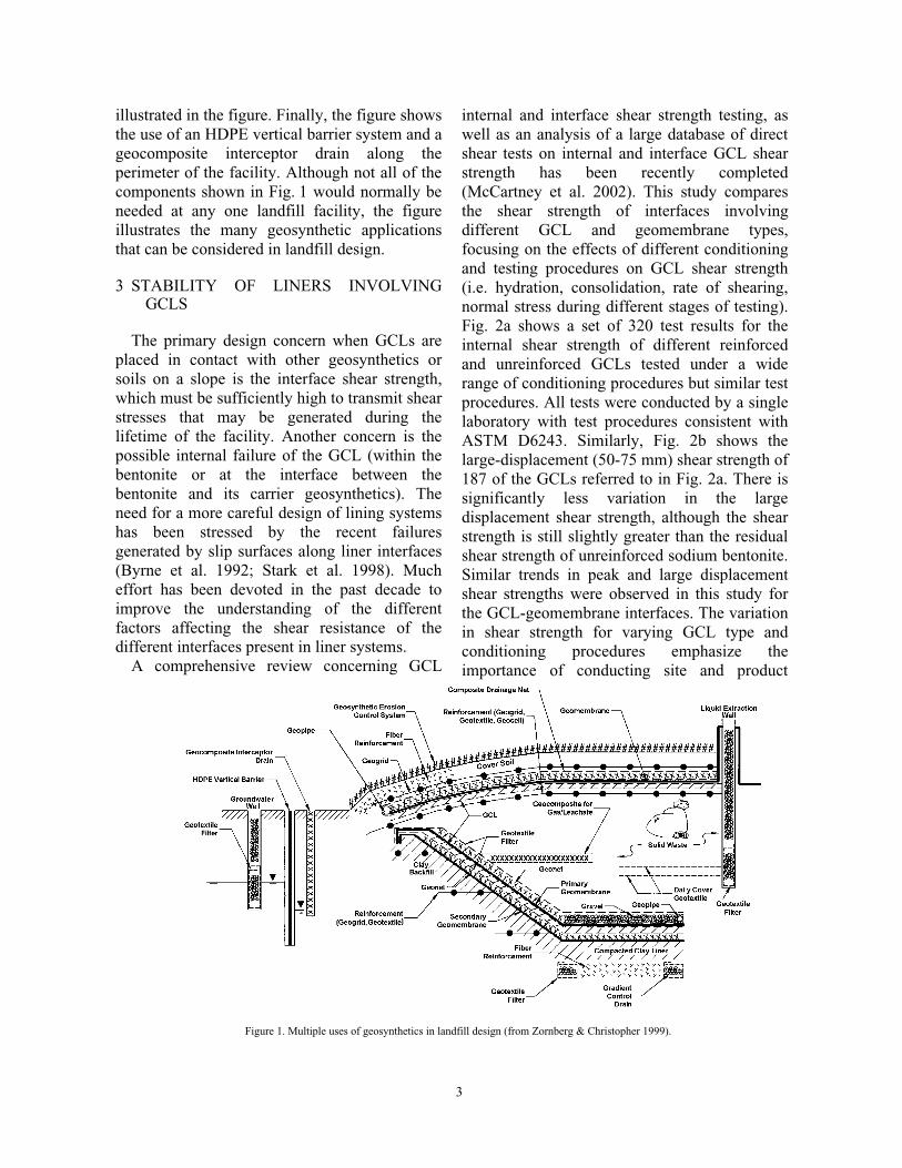
The multiple uses of geosynthetics in thedesign of modern municipal solid waste landfillsis a good illustration of an application in whichthe different geosynthetics can be and have beenused to perform all the functions discussedpreviously. Virtually all the different types ofgeosynthetics discussed previously have beenused in the design of both base and cover linersystems of landfill facilities. Fig. 1 illustrates theextensive multiple uses of geosynthetics in boththe cover and the base liner systems of a modernlandfill facility (Zornberg & Christopher 1999).The base liner system illustrated in Fig. 1 is adouble composite liner system. Doublecomposite liner systems are used in someinstances for containment of municipal solidwaste and are frequently used for landfillsdesigned to contain hazardous waste. The baseliner system shown in the figure includes ageomembrane/GCL composite as the primaryliner system and a geomembrane/compactedclay liner composite as the secondary system.The leak detection system, located between theprimary and secondary liners, is ageotextile/geonet composite. The leachatecollection system overlying the primary liner onthe bottom of the liner system consists of gravelwith a network of perforated pipes. A geotextileprotection layer beneath the gravel provides acushion to protect the primary geomembranefrom puncture by stones in the overlying gravel.The leachate collection system overlying the
primary liner on the side slopes of the linersystem is a geocomposite sheet drain(geotextile/geonet composite) merging into thegravel on the base. A geotextile filter covers theentire footprint of the landfill and preventsclogging of the leachate collection and removalsystem. The groundwater level may becontrolled at the bottom of the landfill bygradient control drains built using geotextilefilters. Moreover, the foundation soil below thebottom of the landfill may be stabilized asshown in the figure using randomly distributedfiber reinforcements, while the steep side soilslopes beneath the liner could also be reinforcedusing geogrids. Different types of geosynthetics(e.g. geogrids, geotextiles, fibers) could havebeen selected for stabilization of the foundationsoils.
The cover system of the landfill illustrated inFig. 1 contains a composite geomembrane/GCLbarrier layer. The drainage layer overlying thegeomembrane is a geocomposite sheet drain(composite geotextile/geonet). In addition, thesoil cover system may include geogrid,geotextile, or geocell reinforcements below theinfiltration barrier system. This layer ofreinforcements may be used to minimize thestrains that could be induced in the barrier layersby differential settlements of the refuse or by afuture vertical expansion of the landfill. Inaddition, the cover system could include ageogrid or geotextile reinforcement above theinfiltration barrier to provide stability to thevegetative cover soil. Fiber reinforcement mayalso be used for stabilization of the steep portionof the vegetative cover soil. A geocompositeerosion control system above the vegetativecover soil is indicated in the figure and providesprotection against sheet and gully erosion. Fig. 1also illustrates the use of geosynthetics withinthe waste mass, which are used to facilitatewaste placement during landfilling. Specifically,the figure illustrates the use of geotextiles asdaily cover layers and of geocomposites withinthe waste mass for collection of gas andleachate. Geosynthetics can also be used as partof the groundwater and leachate collection wellsystem. The use of geotextiles as filters ingroundwater and leachate extraction wells is
3
illustrated in the figure. Finally, the figure showsthe use of an HDPE vertical barrier system and ageocomposite interceptor drain along theperimeter of the facility. Although not all of thecomponents shown in Fig. 1 would normally beneeded at any one landfill facility, the figureillustrates the many geosynthetic applicationsthat can be considered in landfill design.
3 STABILITY OF LINERS INVOLVINGGCLS
The primary design concern when GCLs areplaced in contact with other geosynthetics orsoils on a slope is the interface shear strength,which must be sufficiently high to transmit shearstresses that may be generated during thelifetime of the facility. Another concern is thepossible internal failure of the GCL (within thebentonite or at the interface between thebentonite and its carrier geosynthetics). Theneed for a more careful design of lining systemshas been stressed by the recent failuresgenerated by slip surfaces along liner interfaces(Byrne et al. 1992; Stark et al. 1998). Mucheffort has been devoted in the past decade toimprove the understanding of the differentfactors affecting the shear resistance of thedifferent interfaces present in liner systems.
A comprehensive review concerning GCL
internal and interface shear strength testing, aswell as an analysis of a large database of directshear tests on internal and interface GCL shearstrength has been recently completed(McCartney et al. 2002). This study comparesthe shear strength of interfaces involvingdifferent GCL and geomembrane types,focusing on the effects of different conditioningand testing procedures on GCL shear strength(i.e. hydration, consolidation, rate of shearing,normal stress during different stages of testing).Fig. 2a shows a set of 320 test results for theinternal shear strength of different reinforcedand unreinforced GCLs tested under a widerange of conditioning procedures but similar testprocedures. All tests were conducted by a singlelaboratory with test procedures consistent withASTM D6243. Similarly, Fig. 2b shows thelarge-displacement (50-75 mm) shear strength of187 of the GCLs referred to in Fig. 2a. There issignificantly less variation in the largedisplacement shear strength, although the shearstrength is still slightly greater than the residualshear strength of unreinforced sodium bentonite.Similar trends in peak and large displacementshear strengths were observed in this study forthe GCL-geomembrane interfaces. The variationin shear strength for varying GCL type andconditioning procedures emphasize theimportance of conducting site and product
Figure 1. Multiple uses of geosynthetics in landfill design (from Zornberg & Christopher 1999).

4
specific laboratory testing for internal andinterface GCL shear strength.
McCartney et al. (2002) propose that theconditioning and testing procedures affect theswelling behavior of the GCL, resulting invariable material properties and either positiveor negative excess pore water pressuresgenerated during shearing. Variability associatedwith the swelling of the GCL is ultimatelyrelated to the variability in the internal orinterface shear strength. These results aregenerally consistent with laboratory resultsconducted in several other studies (Stark & Eid1996, Gilbert et al. 1996, Eid & Stark 1997, Foxet al. 1998a) on the internal strength ofunreinforced and reinforced (stitch bonded andneedle punched) GCLs. Peak shear strengths forthe unreinforced GCL products were found to besimilar and comparable to those for sodiumbentonite (i.e. very low shear strength), whichmakes them prone to instability. Because of this,unreinforced GCLs are usually notrecommended for slopes steeper than 10H:1V(Frobel 1996; Richardson 1997). On the otherhand, reinforced GCLs have higher internal peakstrength due to the presence of fiberreinforcements. The behavior of reinforcedGCLs has been shown to depend on theresistance against pullout and/or tensile ruptureof the fibers reinforcements and the shearstrength of the bentonite (at large displacementsonce the fibers have failed). The peak shear
strength of different types of reinforced GCLs(needle-punched, thermal bonded, stitch-bonded) may differ significantly (McCartney etal. 2002). It is worth noting that despite the factthat internal failure of reinforced GCLs couldpossibly occur in the laboratory, there are noknown cases of slope failures that can beattributed to internal shear failure of reinforcedGCLs.
Laboratory interface shear tests are routinelyconducted to evaluate interface friction betweenGCLs and soils or geosynthetics under operatingconditions. As a result, a more extensivedatabase is now available (Garcin et al. 1995;Bressi et al. 1995; Feki et al. 1997; Gilbert et al.1996; Von Maubeuge & Eberle 1998; Eid et al.1999; Triplett & Fox 2001; McCartney et al.2002). The major finding worth noting is thepossible reduction in frictional resistancebetween a geomembrane and a GCL due toextrusion of bentonite through wovengeotextiles and nonwoven geotextiles with amass per unit area less than 220 g/m2 into theadjacent geomembrane interface.
McCartney et al. (2002) observed thatdifferent reinforced GCLs would experiencedifferent interface shear strengths, implying thatsodium bentonite extrusion from the GCL isrelated to the internal fiber reinforcements inaddition to the conditioning procedures.
Despite the observed difference betweeninternal and interface GCL shear strength,
0
50
100
150
200
250
300
350
400
450
500
0 50 100 150 200 250 300 350 400 450 500 550
Normal Stress, kPa
Pea
k S
hear
Str
engt
h, k
Pa
All Reinforced GCLs - 313 Tests
All Unreinforced GCLs - 7 Tests
100
50
200
300
400500600700800850
0
50
100
150
200
250
300
350
400
450
500
0 50 100 150 200 250 300 350 400 450 500 550
Normal Stress, kPa
Larg
e D
ispl
acem
ent S
hear
Str
engt
h, k
Pa All GCLs - 180 Tests
All Unreinforced GCLs - 7 Tests
100
50
200
300
400500600700800850
(a) (b)
Figure 2. Reinforced and unreinforced GCLs, (a) Peak shear strength (b) Large-displacement shear strength (McCartney et al. 2002)
5
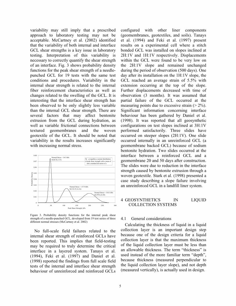
variability may still imply that a prescribedapproach to laboratory testing may not beacceptable. McCartney et al. (2002) identifiedthat the variability of both internal and interfaceGCL shear strengths is a key issue in laboratorytesting. Interpretation of this variability isnecessary to correctly quantify the shear strengthof an interface. Fig. 3 shows probability densityfunctions for the peak shear strength of a needle-punched GCL for 19 tests with the same testconditions and procedures. Variability in theinternal shear strength is related to the internalfiber reinforcement characteristics as well aschanges related to the swelling of the GCL. It isinteresting that the interface shear strength hasbeen observed to be only slightly less variablethan the internal GCL shear strength. There areseveral factors that may affect bentoniteextrusion from the GCL during hydration, aswell as variable frictional connections betweentextured geomembranes and the wovengeotextile of the GCL. It should be noted thatvariability in the results increases significantlywith increasing normal stress.
0
0.01
0.02
0.03
0.04
0.05
0.06
0.07
0.08
0 50 100 150 200 250 300
Peak Shear Strength, kPa
Pro
babi
lity
Den
sity
Normal Stress = 34.5 kPaN(46.92,5.33) N( ,s) signifies a normal distribution
of peak shear strength with a mean of and a standard deviation of s
Normal Stress = 137.9 kPaN(110.35,16.36)
Normal Stress = 310.3 kPaN(199.8,24.88)
Figure 3. Probability density functions for the internal peak shearstrength of a needle-punched GCL, developed from 19 test series of threedifferent normal stresses (McCartney et al. 2002)
No full-scale field failures related to theinternal shear strength of reinforced GCLs havebeen reported. This implies that field-testingmay be required to truly determine the criticalinterface in a layered system. Tanays et al.(1994), Feki et al. (1997) and Daniel et al.(1998) reported the findings from full scale fieldtests of the internal and interface shear strengthbehaviour of unreinforced and reinforced GCLs
configured with other liner components(geomembranes, geotextiles, and soils). Tanayset al. (1994) and Feki et al. (1997) presentresults on a experimental cell where a stitchbonded GCL was installed on slopes inclined at2H:1V and 1H:1V respectively. Displacementswithin the GCL were found to be very low onthe 2H:1V slope and remained unchangedduring the period of observation (500 days). Oneday after its installation on the 1H:1V slope, theGCL reached an average strain of 5.5% withextension occurring at the top of the slope.Further displacements decreased with time ofobservation (3 months). It was assumed thatpartial failure of the GCL occurred at themeasuring points due to excessive strain (> 2%).Significant information concerning interfacebehaviour has been gathered by Daniel et al.(1998). It was reported that all geosyntheticconfigurations on test slopes inclined at 3H:1Vperformed satisfactorily. Three slides haveoccurred on steeper slopes (2H:1V). One slideoccurred internally in an unreinforced GCL (ageomembrane backed GCL) because of sodiumbentonite hydration. Two slides occurred at theinterface between a reinforced GCL and ageomembrane 20 and 50 days after construction.The slides were due to reduction in the interfacestrength caused by bentonite extrusion through awoven geotextile. Stark et al. (1998) presented acase study describing a slope failure involvingan unreinforced GCL in a landfill liner system.
4 GEOSYNTHETICS IN LIQUIDCOLLECTION SYSTEMS
4.1 General considerationsCalculating the thickness of liquid in a liquid
collection layer is an important design stepbecause one of the design criteria for a liquidcollection layer is that the maximum thicknessof the liquid collection layer must be less thanan allowable thickness. The term “thickness” isused instead of the more familiar term “depth”,because thickness (measured perpendicular tothe liquid collection layer slope), and not depth(measured vertically), is actually used in design.
6
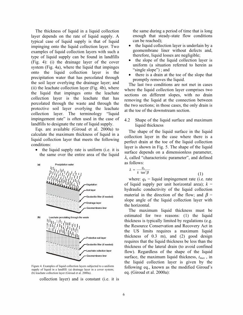
Figure 4. Examples of liquid collection layers subjected to a uniformsupply of liquid in a landfill: (a) drainage layer in a cover system;(b) leachate collection layer (Giroud et al. 2000a).
The thickness of liquid in a liquid collectionlayer depends on the rate of liquid supply. Atypical case of liquid supply is that of liquidimpinging onto the liquid collection layer. Twoexamples of liquid collection layers with such atype of liquid supply can be found in landfills(Fig. 4): (i) the drainage layer of the coversystem (Fig. 4a), where the liquid that impingesonto the liquid collection layer is theprecipitation water that has percolated throughthe soil layer overlying the drainage layer; and(ii) the leachate collection layer (Fig. 4b), wherethe liquid that impinges onto the leachatecollection layer is the leachate that haspercolated through the waste and through theprotective soil layer overlying the leachatecollection layer. The terminology “liquidimpingement rate” is often used in the case oflandfills to designate the rate of liquid supply.
Eqs. are available (Giroud et al. 2000a) tocalculate the maximum thickness of liquid in aliquid collection layer that meets the followingconditions:
• the liquid supply rate is uniform (i.e. it isthe same over the entire area of the liquid
collection layer) and is constant (i.e. it is
the same during a period of time that is longenough that steady-state flow conditionscan be reached);
• the liquid collection layer is underlain by ageomembrane liner without defects and,therefore, liquid losses are negligible;
• the slope of the liquid collection layer isuniform (a situation referred to herein as“single slope”) ; and
• there is a drain at the toe of the slope thatpromptly removes the liquid.
The last two conditions are not met in caseswhere the liquid collection layer comprises twosections on different slopes, with no drainremoving the liquid at the connection betweenthe two sections; in those cases, the only drain isat the toe of the downstream section.
4.2 Shape of the liquid surface and maximumliquid thickness
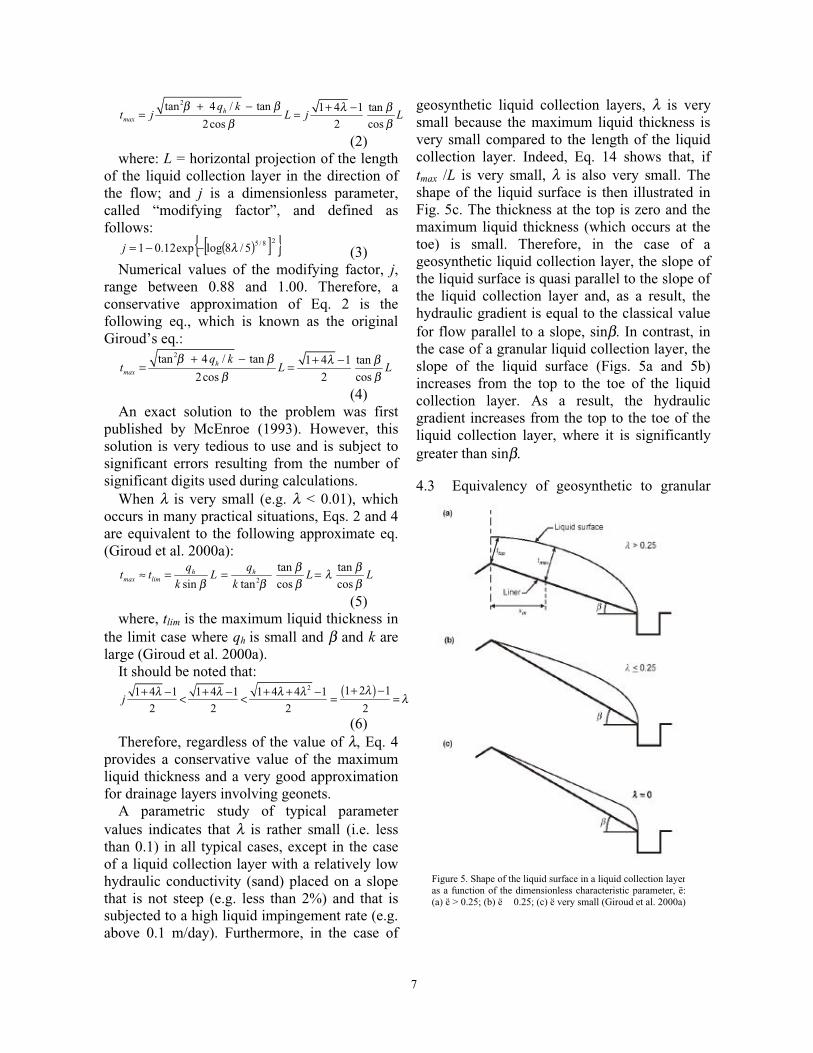
The shape of the liquid surface in the liquidcollection layer in the case where there is aperfect drain at the toe of the liquid collectionlayer is shown in Fig. 5. The shape of the liquidsurface depends on a dimensionless parameter,λ, called “characteristic parameter”, and definedas follows:
2tanhq
kλ
β=
(1)where: qh = liquid impingement rate (i.e. rate
of liquid supply per unit horizontal area); k =hydraulic conductivity of the liquid collectionmaterial in the direction of the flow; and β =slope angle of the liquid collection layer withthe horizontal.
The maximum liquid thickness must beestimated for two reasons: (1) the liquidthickness is typically limited by regulations (e.g.the Resource Conservation and Recovery Act inthe US limits requires a maximum liquidthickness of 0.3 m), and (2) good designrequires that the liquid thickness be less than thethickness of the lateral drain (to avoid confinedflow). Regardless of the shape of the liquidsurface, the maximum liquid thickness, tmax , inthe liquid collection layer is given by thefollowing eq., known as the modified Giroud’seq. (Giroud et al. 2000a):
7
Figure 5. Shape of the liquid surface in a liquid collection layeras a function of the dimensionless characteristic parameter, ë:(a) ë > 0.25; (b) ë 0.25; (c) ë very small (Giroud et al. 2000a)
2tan 4 / tan 1 4 1 tan
2cos 2 cosh
max
q kt j L j L
β β λ ββ β
+ − + −= =
(2)where: L = horizontal projection of the length
of the liquid collection layer in the direction ofthe flow; and j is a dimensionless parameter,called “modifying factor”, and defined asfollows:
( )[ ]{ }28/55/8logexp12.01 λ−−=j (3)Numerical values of the modifying factor, j,
range between 0.88 and 1.00. Therefore, aconservative approximation of Eq. 2 is thefollowing eq., which is known as the originalGiroud’s eq.:
2tan 4 / tan 1 4 1 tan
2cos 2 cosh
max
q kt L L
β β λ ββ β
+ − + −= =
(4)An exact solution to the problem was first
published by McEnroe (1993). However, thissolution is very tedious to use and is subject tosignificant errors resulting from the number ofsignificant digits used during calculations.
When λ is very small (e.g. λ < 0.01), whichoccurs in many practical situations, Eqs. 2 and 4are equivalent to the following approximate eq.(Giroud et al. 2000a):
2
tan tan
sin tan cos cosh h
max lim
q qt t L L L
k k
β βλβ β β β
≈ = = =
(5)where, tlim is the maximum liquid thickness in
the limit case where qh is small and β and k arelarge (Giroud et al. 2000a).
It should be noted that:( )2 1 2 11 4 1 1 4 1 1 4 4 1
2 2 2 2j
λλ λ λ λ λ+ −+ − + − + + −< < = =
(6)Therefore, regardless of the value of λ, Eq. 4
provides a conservative value of the maximumliquid thickness and a very good approximationfor drainage layers involving geonets.
A parametric study of typical parametervalues indicates that λ is rather small (i.e. lessthan 0.1) in all typical cases, except in the caseof a liquid collection layer with a relatively lowhydraulic conductivity (sand) placed on a slopethat is not steep (e.g. less than 2%) and that issubjected to a high liquid impingement rate (e.g.above 0.1 m/day). Furthermore, in the case of
geosynthetic liquid collection layers, λ is verysmall because the maximum liquid thickness isvery small compared to the length of the liquidcollection layer. Indeed, Eq. 14 shows that, iftmax /L is very small, λ is also very small. Theshape of the liquid surface is then illustrated inFig. 5c. The thickness at the top is zero and themaximum liquid thickness (which occurs at thetoe) is small. Therefore, in the case of ageosynthetic liquid collection layer, the slope ofthe liquid surface is quasi parallel to the slope ofthe liquid collection layer and, as a result, thehydraulic gradient is equal to the classical valuefor flow parallel to a slope, sinβ. In contrast, inthe case of a granular liquid collection layer, theslope of the liquid surface (Figs. 5a and 5b)increases from the top to the toe of the liquidcollection layer. As a result, the hydraulicgradient increases from the top to the toe of theliquid collection layer, where it is significantlygreater than sinβ.
4.3 Equivalency of geosynthetic to granular
8
lateral drainsRegulatory equivalency between natural and
geocomposite lateral drainage systems iscurrently based on equivalent transmissivity.However, Giroud et al. (2000c) havedemonstrated that this practice is incorrect andnon-conservative. An equivalency based solelyon transmissivity will lead to selection of ageosynthetic drainage layer that may not provideadequate flow capacity and may result in thedevelopment of water pressure.
Equivalency between two lateral drainagesystems must take into consideration the serviceflow gradients and maximum liquid thickness.Giroud et al. (2000c) have shown that, to beequivalent to a natural drainage layer, theminimum transmissivity of the geocompositemust be greater than the tranmissivity of thenatural drainage layer. The minimumtransmissivity of the geonet is obtained bymultiplying the transmissivity of the naturaldrainage layer by an equivalency factor, E. Fornatural drainage layers having maximum flowdepths of 0.30 m, E can be approximated asfollows:
+
ββ
tancos
88.01
88.01
L
t=E prescribed
(7)where tprescribed is the maximum liquid
thickness prescribed by regulations. Theequivalency defined by Eq. 7 is based on equalunconfined flow volumes in natural andgeocomposite drainage systems. However, thevery low heads associated with unconfined flowin a geocomposite lateral drain will result in asignificantly reduced head acting on theunderlying liner system, and therefore in areduced potential leakage.
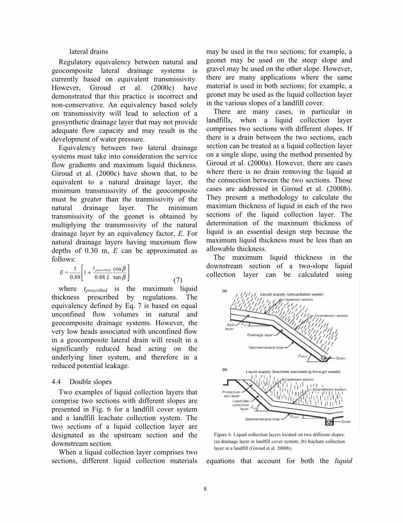
4.4 Double slopesTwo examples of liquid collection layers that
comprise two sections with different slopes arepresented in Fig. 6 for a landfill cover systemand a landfill leachate collection system. Thetwo sections of a liquid collection layer aredesignated as the upstream section and thedownstream section.
When a liquid collection layer comprises twosections, different liquid collection materials
may be used in the two sections; for example, ageonet may be used on the steep slope andgravel may be used on the other slope. However,there are many applications where the samematerial is used in both sections; for example, ageonet may be used as the liquid collection layerin the various slopes of a landfill cover.
There are many cases, in particular inlandfills, when a liquid collection layercomprises two sections with different slopes. Ifthere is a drain between the two sections, eachsection can be treated as a liquid collection layeron a single slope, using the method presented byGiroud et al. (2000a). However, there are caseswhere there is no drain removing the liquid atthe connection between the two sections. Thosecases are addressed in Giroud et al. (2000b).They present a methodology to calculate themaximum thickness of liquid in each of the twosections of the liquid collection layer. Thedetermination of the maximum thickness ofliquid is an essential design step because themaximum liquid thickness must be less than anallowable thickness.
The maximum liquid thickness in thedownstream section of a two-slope liquidcollection layer can be calculated using
equations that account for both the liquid
Figure 6. Liquid collection layers located on two different slopes:(a) drainage layer in landfill cover system; (b) leachate collectionlayer in a landfill (Giroud et al. 2000b).
9
impinging onto the downstream section and theliquid impinging onto, and flowing from, theupstream section. The maximum liquidthickness in the upstream section of a two-slopeliquid collection layer can be calculated usingequations that depend on the material used in theupstream section and in the downstream section.In some cases, a transition zone is neededbetween the upstream and downstream sections.
5 REINFORCED COVER SYSTEMS
5.1 General considerationsThe design of veneer slopes (e.g. steep cover
systems for waste containment facilities) posessignificant challenges to designers. The use ofuniaxial reinforcements placed along the slope(under the veneer and above a typically strongmass of soil or solid waste) and anchored on thetop of the slope has been a common designapproach. However, this alternative may not befeasible for steep, long veneer slopes. As theveneer slope rests on top of a comparativelystronger mass solid waste, alternativeapproaches can be considered. This includes useof uniaxial reinforcements placed horizontally(rather than along the slope) and anchored intothe underlying mass. A second alternativeincludes the use of fiber-reinforced soil. Areview of analyses for veneers reinforced usinghorizontally placed inclusions is presented inthis section.
This section presents an analytical frameworkfor quantification of the reinforcementrequirements for reinforced veneers wherereinforcements are placed horizontally andembedded into a comparatively strongunderlying mass. Emphasis in this evaluation isplaced on the assessment of an infinite slopeconfirguration. This allows direct comparison ofthe different reinforcement alternatives.
Design criteria for reinforced soil structurehave been the focus of significant debate(Zornberg & Leshchinsky 2001). Althoughdifferent definitions for the factor of safety havebeen reported for the design of reinforced soilslopes, the definition used in this study isrelative to the shear strength of the soil:
Available soil shear strengthFS =
Soil shear stress required for equilibrium (8)This definition is consistent with conventional
limit equilibrium analysis, for which extensiveexperience has evolved for the analysis ofunreinforced slopes. Current design practices forreinforced soil slopes often consider approachesthat decouple the soil reinforcement interactionand do not strictly consider the factor of safetydefined by Eq. 8. Such analyses neglect theinfluence of reinforcement forces on the soilstresses along the potential failure surface andmay result in factors of safety significantlydifferent than those calculated using morerigorous approaches. Considering the normaland shear forces acting in a control volumealong the veneer slope (or infinite slope), andassuming a Mohr-Coulomb shear strengthenvelope, Eq. 8 can be expressed as:
LS
LNc=FS
/
tan)/( φ+
(9)where N = normal force acting on the controlvolume; S = shear force acting on the controlvolume; L = length of the control volume; c =soil cohesion; and φ = soil friction angle.
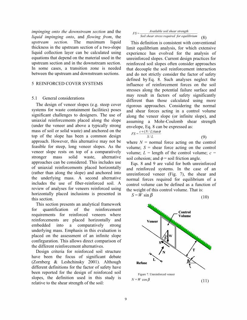
Eqs. 8 and 9 are valid for both unreinforcedand reinforced systems. In the case of anunreinforced veneer (Fig. 7), the shear andnormal forces required for equilibrium of acontrol volume can be defined as a function ofthe weight of this control volume. That is:
βsinW=S (10)
βcosW=N (11)
Refuse
Veneer
ControlVolume
T
ββ
ββ W
L
N
S
Refuse
Veneer
ControlVolume
T
ββ
ββ W
L
N
S
Figure 7. Unreinforced veneer
10
TL=W γ (12)where W = weight of the control volume; β =slope inclination; T = veneer thickness; and γ =soil total unit weight.
From the previous equations, the classicexpression for the factor of safety FSu of anunreinforced veneer can be obtained:
βφ
βγ tan
tan
sin+
T
c=FSu
(13)
5.2 Covers reinforced with uniaxialgeosynthetics parallel to the slope
Fig.8 shows a schematic representation of acover system reinforced using uniaxialgeosynthetics placed parallel to the slope. Aninfinite slope case is considered. In the case, theshear force needed for equilibrium of the controlvolume is smaller that the one in theunreinforced case. In this case, the shear force isdefined by:
LtW=S p−βsin (14)where tp = distributed reinforcement tensilestress of the reinforcement parallel to the slope.When the geosynthetic reinforcements areplaced parallel to the slope, the distributedreinforcement tensile stress is a function of theallowable reinforcement tensile strength (Ta) andthe total slope length (LT), as follows:
T
ap L
Tt =
(15)
From eqs. 18, 20, 21 and 23, the factor ofsafety for the parallel-reinforcement case, FSr,p ,can be estimated as:
βγ
βφ
βγ
sin1
tan
tan
sin,
T
tT
c
=FSp
pr
−
+
(16)The eq. above can be simplified by defining
the normalized distributed reinforcement tensilestress tp
* (dimensionless), as follows:
T
t=t p
p γ*
(17)Using Eqs. 22 and 26 into Eq. 25:
βsin1
1 *,
p
upr
t
FS=FS
−(18)
Eq. 18 provides a convenient expression forstability evaluation of reinforced veneer slopes.It should be noted that if the distributedreinforcement tensile stress t equals zero (i.e. inthe case of unreinforced veneers), Eq. 18 leadsto FSr,p = FSu .
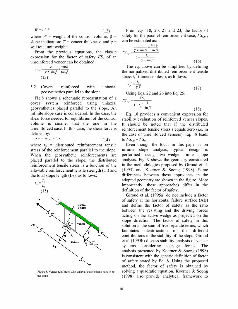
Even though the focus in this paper is oninfinite slope analysis, typical design isperformed using two-wedge finite slopeanalysis. Fig. 9 shows the geometry consideredin the methodologies proposed by Giroud et al.(1995) and Koerner & Soong (1998). Somedifferences between these approaches in theadopted geometry are shown in the figure. Moreimportantly, these approaches differ in thedefinition of the factor of safety.
Giroud et al. (1995a) do not include a factorof safety at the horizontal failure surface (AB)and define the factor of safety as the ratiobetween the resisting and the driving forcesacting on the active wedge as projected on theslope direction. The factor of safety in thissolution is the sum of five separate terms, whichfacilitates identification of the differentcontributions to the stability of the slope. Giroudet al (1995b) discuss stability analysis of veneersystems considering seepage forces. Theanalysis presented by Koerner & Soong (1998)is consistent with the generic definition of factorof safety stated by Eq. 8. Using the proposedmethod, the factor of safety is obtained bysolving a quadratic equation. Koerner & Soong(1998) also provide analytical framework to
LN
ControlVolume
T
ββ
ββ WS
Refuse
Veneer
LN
ControlVolume
T
ββ
ββ W
tp
S
Ta
LT
LN
ControlVolume
T
ββ
ββ WS
Refuse
Veneer
LN
ControlVolume
T
ββ
ββ W
tp
S
Ta
LTLT
Figure 8. Veneer reinforced with uniaxial geosynthetic parallel tothe slope
11
address cases involving construction equipment,seepage forces, seismic forces, and thestabilizing effects of toe berms, tapered slopesand slope reinforcements. Thiel & Stewart(1993) and Punyamurthula & Hawk (1998)provide additional information regardingstability analysis of steep cover systems.
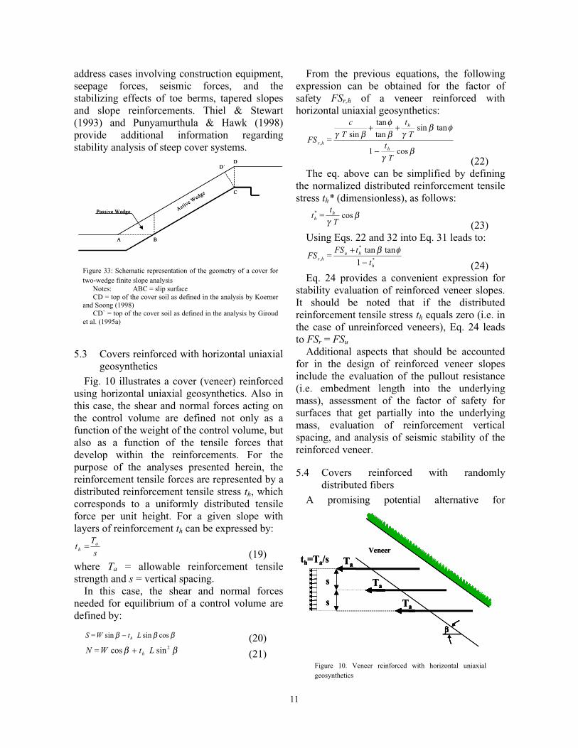
5.3 Covers reinforced with horizontal uniaxialgeosynthetics
Fig. 10 illustrates a cover (veneer) reinforcedusing horizontal uniaxial geosynthetics. Also inthis case, the shear and normal forces acting onthe control volume are defined not only as afunction of the weight of the control volume, butalso as a function of the tensile forces thatdevelop within the reinforcements. For thepurpose of the analyses presented herein, thereinforcement tensile forces are represented by adistributed reinforcement tensile stress th, whichcorresponds to a uniformly distributed tensileforce per unit height. For a given slope withlayers of reinforcement th can be expressed by:
s
Tt a
h =(19)
where Ta = allowable reinforcement tensilestrength and s = vertical spacing.
In this case, the shear and normal forcesneeded for equilibrium of a control volume aredefined by:
βββ cossinsin LtW=S h− (20)ββ 2sincos LtW=N h+ (21)
From the previous equations, the followingexpression can be obtained for the factor ofsafety FSr,h of a veneer reinforced withhorizontal uniaxial geosynthetics:
βγ
φβγβ
φβγ
cos1
tansintan
tan
sin,
T
tT
t
T
c
=FSh
h
hr
−
++
(22)The eq. above can be simplified by defining
the normalized distributed reinforcement tensilestress th* (dimensionless), as follows:
βγ
cos*
T
t=t h
h
(23)Using Eqs. 22 and 32 into Eq. 31 leads to:
*
*
, 1
tantan
h
huhr t
tFS=FS
−+ φβ
(24)Eq. 24 provides a convenient expression for
stability evaluation of reinforced veneer slopes.It should be noted that if the distributedreinforcement tensile stress th equals zero (i.e. inthe case of unreinforced veneers), Eq. 24 leadsto FSr = FSu
Additional aspects that should be accountedfor in the design of reinforced veneer slopesinclude the evaluation of the pullout resistance(i.e. embedment length into the underlyingmass), assessment of the factor of safety forsurfaces that get partially into the underlyingmass, evaluation of reinforcement verticalspacing, and analysis of seismic stability of thereinforced veneer.
5.4 Covers reinforced with randomlydistributed fibers
A promising potential alternative for
Figure 33: Schematic representation of the geometry of a cover fortwo-wedge finite slope analysis
Notes: ABC = slip surfaceCD = top of the cover soil as defined in the analysis by Koerner
and Soong (1998)CD` = top of the cover soil as defined in the analysis by Giroud
et al. (1995a)
A B
C
DD`
Active W
edge
Passive Wedge
A B
C
DD`
Active W
edge
Passive Wedge
Figure 10. Veneer reinforced with horizontal uniaxialgeosynthetics
ββ
Veneer
ββ
Ta
Ta
Ta
s
s
th=Ta/s
ββ
Veneer
ββ
TaTa
TaTa
TaTa
s
s
th=Ta/s

12
stabilization of steep landfill covers involves theuse of fiber-reinforcement. Advantages of fiber-reinforcement over planar reinforcement in thestabilization of landfill covers are:
• Fiber-reinforcement is particularlysuitable for stabilization of veneer slopes,as it provides additional shear strengthunder low confining pressures. A smallincrease of shear strength under lowconfinement has a significant impact on thestability of shallow slopes.
• Randomly distributed fibers helpsmaintaining strength isotropy and do notinduce potential planes of weakness thatcan develope when using planarreinforcement elements.
• No anchorage is needed into solid wasteas in the case of reinforcement withhorizontal geosynthetics or at the crest ofthe slope as in the case of reinforcementparallel to the landfill slope.
• In addition to stabilizing the cover slopes,fiber reinforcement has the potential ofmitigating the potential for crackdevelopment, providing erosion control,and facilitating the establishment ofvegetation.
Relevant contributions have been madetowards the understanding of the behavior offibers. A soil mass reinforced with discrete,randomly distributed fibers is similar to atraditional reinforced soil system in itsengineering properties but mimics admixturestabilization in the method of its preparation(Gray & Al-Refeai 1986; Bouazza & Amokrane1995). Potential advantages of fiber-reinforcedsolutions over the use of other slope stabilizationtechnologies have been identified, for example,for slope repairs in transportation infrastructureprojects (Gregory & Chill 1998) and for the useof recycled and waste products such as shreddedtires in soil reinforcement (Foose et al. 1996).Micro-reinforcement techniques for soils alsoinclude the use of “Texol”, which consists ofmonofilament fibers injected randomly into sand(Leflaive 1985) and the use of randomlydistributed polymeric mesh elements (McGownet al. 1985; Morel & Gourc 1997). The use offiber-reinforced clay backfill to mitigate thedevelopment of tension cracks was evaluated by
several investigators (e.g. Al Wahab & El-Kedrah 1995). Several composite models havebeen proposed in the literature to explain thebehavior of randomly distributed fibers within asoil mass. The proposed models have beenbased on mechanistic approaches (Maher &Gray 1990), on energy dissipation approaches(Michalowski & Zhao 1996), and on statistics-based approaches (Ranjar et al. 1996).
• Fiber-reinforced soil has often beencharacterized as a single homogenizedmaterial, which has required laboratorycharacterization of composite fiber-reinforced soil specimen. The need forlaboratory characterization has been amajor drawback in the implementation offiber-reinforcement in soil stabilizationprojects. To overcome this difficulty, adiscrete approach that characterizes thefiber-reinforced soil as a two-component(fibers and soil) material was recentlydeveloped (Zornberg 2002). The mainfeatures of this approach are:
• The reinforced mass is characterized bythe mechanical properties of individualfibers and of the soil matrix rather than bythe mechanical properties of the fiber-reinforced composite material
• A critical confining pressure at which thegoverning mode of failure changes fromfiber pullout to fiber breakage can bedefined using the individual fiber and soilmatrix properties.
• The fiber-induced distributed tension is afunction of fiber content, fiber aspect ratio,and interface shear strength of individualfibers if the governing mode of failure is byfiber pullout.
• The fiber-induced distributed tension is afunction of fiber content and ultimatetensile strength of individual fibers if thegoverning mode of failure is by fiberbreakage.
• The discrete framework can beimplemented into an infinite slope limitequilibrium framework. Convenientexpressions can be obtained to estimatedirectly the required fiber content toachieve a target factor of safety.
The design methodology for fiber-reinforcedsoil structures using a discrete approach is
13
consistent with current design guidelines for theuse of continuous planar reinforcements and withthe actual soil improvement mechanisms.Consequently, fiber-reinforced cover systems areexpected to become an economical andtechnically superior alternative for reinforcementof landfill covers.
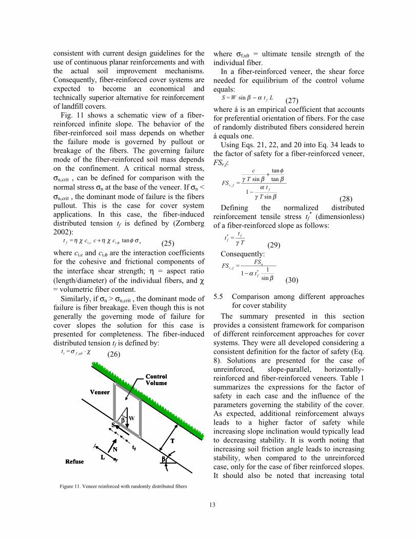
Fig. 11 shows a schematic view of a fiber-reinforced infinite slope. The behavior of thefiber-reinforced soil mass depends on whetherthe failure mode is governed by pullout orbreakage of the fibers. The governing failuremode of the fiber-reinforced soil mass dependson the confinement. A critical normal stress,σn,crit , can be defined for comparison with thenormal stress σn at the base of the veneer. If σn <σn,crit , the dominant mode of failure is the fiberspullout. This is the case for cover systemapplications. In this case, the fiber-induceddistributed tension tf is defined by (Zornberg2002):
nicif ccc=t σφχηχη φ tan,, + (25)where ci,c and ci,φ are the interaction coefficientsfor the cohesive and frictional components ofthe interface shear strength; η = aspect ratio(length/diameter) of the individual fibers, and χ= volumetric fiber content.
Similarly, if σn > σn,crit , the dominant mode offailure is fiber breakage. Even though this is notgenerally the governing mode of failure forcover slopes the solution for this case ispresented for completeness. The fiber-induceddistributed tension tf is defined by:
χσ ⋅ultft =t , (26)
where σf,ult = ultimate tensile strength of theindividual fiber.
In a fiber-reinforced veneer, the shear forceneeded for equilibrium of the control volumeequals:
LtW=S fαβ −sin (27)where á is an empirical coefficient that accountsfor preferential orientation of fibers. For the caseof randomly distributed fibers considered hereiná equals one.
Using Eqs. 21, 22, and 20 into Eq. 34 leads tothe factor of safety for a fiber-reinforced veneer,FSr,f:
βγα
βφ
βγ
sin1
tan
tan
sin,
T
tT
c
=FSf
fr
−
+
(28)Defining the normalized distributed
reinforcement tensile stress tf* (dimensionless)
of a fiber-reinforced slope as follows:
T
t=t f
f γ*
(29)Consequently:
βα
sin1
1 *,
f
ufr
t
FS=FS
−(30)
5.5 Comparison among different approachesfor cover stability
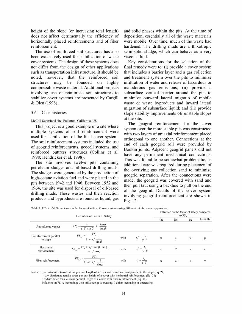
The summary presented in this sectionprovides a consistent framework for comparisonof different reinforcement approaches for coversystems. They were all developed considering aconsistent definition for the factor of safety (Eq.8). Solutions are presented for the case ofunreinforced, slope-parallel, horizontally-reinforced and fiber-reinforced veneers. Table 1summarizes the expressions for the factor ofsafety in each case and the influence of theparameters governing the stability of the cover.As expected, additional reinforcement alwaysleads to a higher factor of safety whileincreasing slope inclination would typically leadto decreasing stability. It is worth noting thatincreasing soil friction angle leads to increasingstability, when compared to the unreinforcedcase, only for the case of fiber reinforced slopes.It should also be noted that increasing total
Figure 11. Veneer reinforced with randomly distributed fibers
Refuse
Veneer
LN
ControlVolume
T
ββ
ββ WS
Refuse
Veneer
LN
ControlVolume
T
ββ
ββ W
tf
S
Refuse
Veneer
LN
ControlVolume
T
ββ
ββ WS
Refuse
Veneer
LN
ControlVolume
T
ββ
ββ W
tf
S
14
height of the slope (or increasing total length)does not affect detrimentally the efficiency ofhorizontally placed reinforcements and of fiberreinforcement.
The use of reinforced soil structures has alsobeen extensively used for stabilization of wastecover systems. The design of these systems doesnot differ from the design of other applicationssuch as transportation infrastructure. It should benoted, however, that the reinforced soilstructures may be founded on highlycompressible waste material. Additional projectsinvolving use of reinforced soil structures tostabilize cover systems are presented by Cargill& Olen (1998).
5.6 Case histories
McColl Superfund site, Fullerton, California, US
This project is a good example of a site wheremultiple systems of soil reinforcement wereused for stabilization of the final cover system.The soil reinforcement systems included the useof geogrid reinforcements, geocell systems, andreinforced buttress structures (Collins et al.1998; Hendricker et al. 1998).
The site involves twelve pits containingpetroleum sludges and oil-based drilling muds.The sludges were generated by the production ofhigh-octane aviation fuel and were placed in thepits between 1942 and 1946. Between 1952 and1964, the site was used for disposal of oil-baseddrilling muds. These wastes and their reactionproducts and byproducts are found as liquid, gas
and solid phases within the pits. At the time ofdeposition, essentially all of the waste materialswere mobile. Over time, much of the waste hadhardened. The drilling muds are a thixotropicsemi-solid sludge, which can behave as a veryviscous fluid.
Key considerations for the selection of thefinal remedy were to: (i) provide a cover systemthat includes a barrier layer and a gas collectionand treatment system over the pits to minimizeinfiltration of water and release of hazardous ormalodorous gas emissions; (ii) provide asubsurface vertical barrier around the pits tominimize outward lateral migratio of mobilewaste or waste byproducts and inward lateralmigration of subsurface liquid; and (iii) provideslope stability improvements ofr unstable slopesat the site.
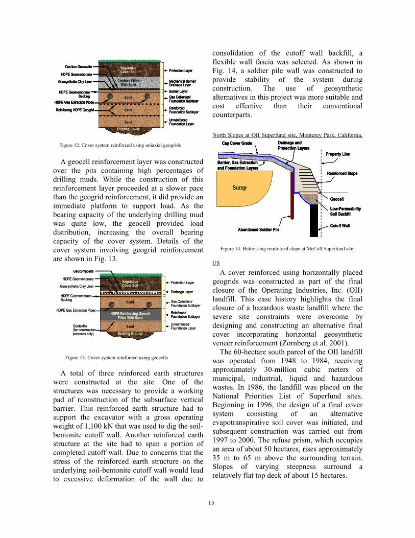
The geogrid reinforcement for the coversystem over the more stable pits was constructedwith two layers of uniaxial reinforcement placedorthogonal to one another. Connections at theend of each geogrid roll were provided byBodkin joints. Adjacent geogrid panels did nothave any permanent mechanical connections.This was found to be somewhat problematic, asadditional care was required during placement ofthe overlying gas collection sand to minimizegeogrid separation. After the connections weremade, the geogrid was covered with sand andthen pull taut using a backhoe to pull on the endof the geogrid. Details of the cover systeminvolving geogrid reinforcement are shown inFig. 12.
Table 1. Effect of different terms in the factor of safety of cover systems using different reinforcement approachesInfluence on the factor of safety compared
to FSuDefinition of Factor of Safetyt*κ βκ φκ LT or HT
Unreinforced veneertan
sin tanu
cFS =
Tφ
γ β β+
Reinforcement parallelto slope
, 11
sin
ur p
np
FSFS =
tβ
− with * pp
t t =
Tγ κ µ ν µ
Horizontalreinforcement ,
sin tan1 cos
nu h
r h nh
FS tFS =
t
β φβ
+−
with* h
h
t t =
Tγ κ ? κ ν
Fiber-reinforcement , 11
sin
ur f
nf
FSFS =
tαβ
− with * ff
t t =
Tγ κ µ κ ν
Notes: tp = distributed tensile stress per unit length of a cover with reinforcement parallel to the slope (Eq. 24)th = distributed tensile stress per unit height of a cover with horizontal reinforcement (Eq. 28)
tf = distributed tensile stress per unit length of a cover with fiber-reinforcement (Eq. 34)Influence on FS: κ increasing; ν no influence; µ decreasing; ? either increasing or decreasing
15
A geocell reinforcement layer was constructedover the pits containing high percentages ofdrilling muds. While the construction of thisreinforcement layer proceeded at a slower pacethan the geogrid reinforcement, it did provide animmediate platform to support load. As thebearing capacity of the underlying drilling mudwas quite low, the geocell provided loaddistribution, increasing the overall bearingcapacity of the cover system. Details of thecover system involving geogrid reinforcementare shown in Fig. 13.
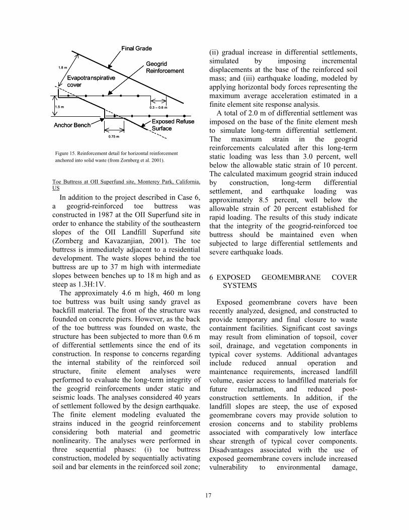
A total of three reinforced earth structureswere constructed at the site. One of thestructures was necessary to provide a workingpad of rconstruction of the subsurface verticalbarrier. This reinforced earth structure had tosupport the excavator with a gross operatingweight of 1,100 kN that was used to dig the soil-bentonite cutoff wall. Another reinforced earthstructure at the site had to span a portion ofcompleted cutoff wall. Due to concerns that thestress of the reinforced earth structure on theunderlying soil-bentonite cutoff wall would leadto excessive deformation of the wall due to
consolidation of the cutoff wall backfill, aflexible wall fascia was selected. As shown inFig. 14, a soldier pile wall was constructed toprovide stability of the system duringconstruction. The use of geosyntheticalternatives in this project was more suitable andcost effective than their conventionalcounterparts.
North Slopes at OII Superfund site, Monterey Park, California,
US
A cover reinforced using horizontally placedgeogrids was constructed as part of the finalclosure of the Operating Industries, Inc. (OII)landfill. This case history highlights the finalclosure of a hazardous waste landfill where thesevere site constraints were overcome bydesigning and constructing an alternative finalcover incorporating horizontal geosyntheticveneer reinforcement (Zornberg et al. 2001).
The 60-hectare south parcel of the OII landfillwas operated from 1948 to 1984, receivingapproximately 30-million cubic meters ofmunicipal, industrial, liquid and hazardouswastes. In 1986, the landfill was placed on theNational Priorities List of Superfund sites.Beginning in 1996, the design of a final coversystem consisting of an alternativeevapotranspirative soil cover was initiated, andsubsequent construction was carried out from1997 to 2000. The refuse prism, which occupiesan area of about 50 hectares, rises approximately35 m to 65 m above the surrounding terrain.Slopes of varying steepness surround arelatively flat top deck of about 15 hectares.
Existing Cover
Sand
Existing Cover
Sand
Sand
VegetativeCover Soil
Sand
Cobbles FilledWith Sand
Protection LayerVegetativeCover Soil
Cobbles FilledWith Sand
Mechanical Barrier/Drainage Layer
Cushion Geotextile
Barrier Layer
HDPE Geomembrane
Geosynthetic Clay Liner
HDPE GeomembraneBacking
UnreinforcedFoundation LayerSand
Sand ReinforcedFoundation SublayerReinforcing HDPE Geogrid
Gas Collection/Foundation SublayerHDPE Gas Extraction Pipes
Sand
Existing Cover
Sand
Existing Cover
Sand
Sand
VegetativeCover Soil
Sand
Cobbles FilledWith Sand
Existing Cover
Sand
Sand
VegetativeCover Soil
Sand
Cobbles FilledWith Sand
Protection LayerVegetativeCover Soil Protection LayerProtection LayerVegetativeCover Soil
Cobbles FilledWith Sand
Mechanical Barrier/Drainage Layer
Cushion Geotextile
Cobbles FilledWith Sand
Mechanical Barrier/Drainage Layer
Cushion Geotextile
Mechanical Barrier/Drainage Layer
Cushion GeotextileCushion Geotextile
Barrier Layer
HDPE Geomembrane
Geosynthetic Clay Liner
HDPE GeomembraneBacking
Barrier Layer
HDPE Geomembrane
Geosynthetic Clay Liner
HDPE GeomembraneBacking
Barrier Layer
HDPE GeomembraneHDPE Geomembrane
Geosynthetic Clay LinerGeosynthetic Clay Liner
HDPE GeomembraneBacking
HDPE GeomembraneBacking
UnreinforcedFoundation LayerSand UnreinforcedFoundation LayerUnreinforcedFoundation LayerSand
Sand ReinforcedFoundation SublayerReinforcing HDPE Geogrid Sand ReinforcedFoundation SublayerReinforcing HDPE Geogrid ReinforcedFoundation SublayerReinforcing HDPE GeogridReinforcing HDPE Geogrid
Gas Collection/Foundation SublayerHDPE Gas Extraction Pipes
Sand Gas Collection/Foundation SublayerHDPE Gas Extraction PipesGas Collection/Foundation SublayerHDPE Gas Extraction PipesGas Collection/Foundation SublayerHDPE Gas Extraction PipesGas Collection/Foundation SublayerHDPE Gas Extraction PipesHDPE Gas Extraction Pipes
Sand
Figure 12. Cover system reinforced using uniaxial geogrids
Protection Layer
Barrier Layer
UnreinforcedFoundation Layer
ReinforcedFoundation Sublayer
Geosynthetic Clay Liner
HDPE GeomembraneBacking
HDPE Gas Extraction Pipes
Geotextile(for constructionpurposes only)
HDPE Geomembrane
Drainage Layer
Geocomposite
Existing Ground
Sand
HDPE Reinforcing GeocellFilled With Sand
Sand
VegetativeCover Soil
Gas Collection/Foundation Sublayer
Protection Layer
Barrier Layer
UnreinforcedFoundation Layer
ReinforcedFoundation SublayerReinforcedFoundation Sublayer
Geosynthetic Clay Liner
HDPE GeomembraneBacking
HDPE Gas Extraction Pipes
Geotextile(for constructionpurposes only)
HDPE Geomembrane
Drainage Layer
Geocomposite
Drainage Layer
Geocomposite
Existing Ground
Sand
HDPE Reinforcing GeocellFilled With Sand
Sand
VegetativeCover Soil
Gas Collection/Foundation Sublayer
Figure 13. Cover system reinforced using geocells
Sump
Property Line
Sump
Cutoff Wall
Geocell
Reinforced Slope
Cap Cover Grade
Abandoned Soldier Pile
Low-PermeabilitySoil Backfill
Barrier, Gas Extraction and Foundation Layers
Drainage andProtection Layers
Sump
Property Line
Sump
Property Line
Sump
Cutoff WallCutoff Wall
Geocell
Reinforced Slope
Cap Cover Grade
Geocell
Reinforced Slope
Cap Cover Grade
Reinforced Slope
Cap Cover GradeCap Cover Grade
Abandoned Soldier PileAbandoned Soldier Pile
Low-PermeabilitySoil Backfill
Barrier, Gas Extraction and Foundation Layers
Drainage andProtection Layers
Low-PermeabilitySoil Backfill
Barrier, Gas Extraction and Foundation Layers
Drainage andProtection Layers
Low-PermeabilitySoil Backfill
Barrier, Gas Extraction and Foundation Layers
Drainage andProtection Layers
Figure 14. Buttressing reinforced slope at McColl Superfund site

16
The final cover design criteria mandated bythe U.S. Environmental Protection Agency(EPA) had to satisfy criteria for percolationperformance, static and seismic stability of thesteep sideslopes of the landfill, and erosioncontrol. Stability criteria required a static factorof safety of 1.5, and acceptable permanentseismically induced deformations less than 150mm under the maximum credible earthquake.The basis of the seismic stability criteria is thatsome limited deformation or damage may resultfrom the design earthquake, and that interim andpermanent repairs would be implemented withina defined period.
One of the most challenging design andconstruction features of the project was relatedto the north slope of the landfill. The north slopeis located immediately adjacent to the heavilytraveled Pomona freeway (over a distance ofabout 1400 meters), rises up to 65 meters abovethe freeway, and consists of slope segments assteep as 1.5:1 (H:V) and up to 30 m highseparated by narrow benches. The toe of theNorth Slope and the edge of refuse extends up tothe freeway. The pre-existing cover on the NorthSlope consisted of varying thickness (a fewcentimeters to several meters) of non-engineeredfill. The cover included several areas ofsloughing instability, chronic cracking and highlevel of gas emissions. The slope was too steepto accommodate a layered final cover system,particularly a cover incorporating geosyntheticcomponents (geomembranes or GCL). Becauseof the height of the slope and lack of space at thetoe, it was not feasible to flatten the slope bypushing out the toe, removing refuse at the top,or constructing a retaining / buttress structure atthe toe of slope.
After evaluating various alternatives, anevapotranspirative cover incorporating geogridreinforcement for veneer stability was selectedas the appropriate cover for the North Slope.The evapotranspirative cover had additionaladvantages over traditional layered coversystems, including superior long-termpercolation performance in arid climates, abilityto accommodate long-term settlements, goodconstructability, and ease of long-termoperations and maintenance. The selected cover
system included the following components,from the top down: 1) vegetation to promoteevapotranspiration and provide erosionprotection; 2) a 1.2 m – thick evapotranspirativesoil layer to provide moisture retention,minimize downward migration of moisture, andprovide a viable zone for root growth; and 3) afoundation layer consisting of soil and refuse ofvariable thickness to provide a firm foundationfor the soil cover system.
Stability analyses showed that for mostavailable evapotranspirative materials,compacted to practically achievable levels ofrelative compaction on a 1.5:1 slope (e.g. 95%of Standard Proctor), the minimum static andseismic stability criteria were not met. Veneergeogrid reinforcement with horizontally placedgeogrids was then selected as the mostappropriate and cost-effective method forstabilizing the North Slope cover. The analyticalframework was used in the design. Fig. 15shows the typical veneer reinforcement detailselected based on the shear strength of the soilsused in construction.
The veneer reinforcement consisted ofpolypropylene uniaxial geogrids, installed at1.5-m vertical intervals for slopes steeper than1.8:1, and at 3-m vertical intervals for slopesbetween 2:1 and 1.8:1. The geogrid panels areembedded a minimum of 0.75 m into theexposed refuse slope face from which the pre-existing cover had been stripped. The geogridpanels were curtailed approximately 0.3 to 0.6 maway from the finished surface of the slopecover. This was done to permit surfaceconstruction, operation and maintenanceactivities on the slope face without the risk ofexposing or snagging the geogrid.
Construction of the North Slope wasaccomplished in 12 months. Approximately500,000 m3 of soil and 170,000 m2 of geogridwere placed. Total area of geogrid placementexceeded 9.3 hectares. The maximum height ofreinforced portion of the landfill slopes was 55m (the maximum height of the total landfillslope was 65 m).
17
Toe Buttress at OII Superfund site, Monterey Park, California,US
In addition to the project described in Case 6,a geogrid-reinforced toe buttress wasconstructed in 1987 at the OII Superfund site inorder to enhance the stability of the southeasternslopes of the OII Landfill Superfund site(Zornberg and Kavazanjian, 2001). The toebuttress is immediately adjacent to a residentialdevelopment. The waste slopes behind the toebuttress are up to 37 m high with intermediateslopes between benches up to 18 m high and assteep as 1.3H:1V.
The approximately 4.6 m high, 460 m longtoe buttress was built using sandy gravel asbackfill material. The front of the structure wasfounded on concrete piers. However, as the backof the toe buttress was founded on waste, thestructure has been subjected to more than 0.6 mof differential settlements since the end of itsconstruction. In response to concerns regardingthe internal stability of the reinforced soilstructure, finite element analyses wereperformed to evaluate the long-term integrity ofthe geogrid reinforcements under static andseismic loads. The analyses considered 40 yearsof settlement followed by the design earthquake.The finite element modeling evaluated thestrains induced in the geogrid reinforcementconsidering both material and geometricnonlinearity. The analyses were performed inthree sequential phases: (i) toe buttressconstruction, modeled by sequentially activatingsoil and bar elements in the reinforced soil zone;
(ii) gradual increase in differential settlements,simulated by imposing incrementaldisplacements at the base of the reinforced soilmass; and (iii) earthquake loading, modeled byapplying horizontal body forces representing themaximum average acceleration estimated in afinite element site response analysis.
A total of 2.0 m of differential settlement wasimposed on the base of the finite element meshto simulate long-term differential settlement.The maximum strain in the geogridreinforcements calculated after this long-termstatic loading was less than 3.0 percent, wellbelow the allowable static strain of 10 percent.The calculated maximum geogrid strain inducedby construction, long-term differentialsettlement, and earthquake loading wasapproximately 8.5 percent, well below theallowable strain of 20 percent established forrapid loading. The results of this study indicatethat the integrity of the geogrid-reinforced toebuttress should be maintained even whensubjected to large differential settlements andsevere earthquake loads.
6 EXPOSED GEOMEMBRANE COVERSYSTEMS
Exposed geomembrane covers have beenrecently analyzed, designed, and constructed toprovide temporary and final closure to wastecontainment facilities. Significant cost savingsmay result from elimination of topsoil, coversoil, drainage, and vegetation components intypical cover systems. Additional advantagesinclude reduced annual operation andmaintenance requirements, increased landfillvolume, easier access to landfilled materials forfuture reclamation, and reduced post-construction settlements. In addition, if thelandfill slopes are steep, the use of exposedgeomembrane covers may provide solution toerosion concerns and to stability problemsassociated with comparatively low interfaceshear strength of typical cover components.Disadvantages associated with the use ofexposed geomembrane covers include increasedvulnerability to environmental damage,
Final Grade
GeogridReinforcement
0.3 – 0.6 m
0.75 m
1.8 m
1.5 m
Anchor Bench
Evapotranspirativecover
Exposed RefuseSurface
Final Grade
GeogridReinforcement
0.3 – 0.6 m
0.75 m
1.8 m
1.5 m
Anchor Bench
Evapotranspirativecover
Exposed RefuseSurface
Figure 15. Reinforcement detail for horizontal reinforcementanchored into solid waste (from Zornberg et al. 2001).
18
increased volume and velocity of stormwaterrunoff, limited regulatory approval, andaesthetics concerns. However, exposedgeomembrane covers have been particularlyapplicable to sites where the design life of thecover is relatively short, when future removal ofthe cover system may be required, when thelandfill sideslopes are steep, when cover soilmaterials are prohibitively expensive, or whenthe landfill is expected to be expanded verticallyin the future. In particular, the current trendstowards the use of “leachate recirculation” orbioreactor landfills makes the use of exposedgeomembrane covers a good choice during theperiod of accelerated settlement of the waste.Key aspects in the design of exposedgeomembrane covers are assessment of thegeomembrane stresses induced by wind upliftand of the anchorage against wind action(Giroud et al. 1995; Zornberg & Giroud1997;Gleason et al. 2001).
6.1 Geomembrane stresses induced by winduplift
The resistance to wind uplift of an exposedgeomembrane cover is a governing factor in itsdesign. Wind uplift of the geomembrane is afunction of the mechanical properties of thegeomembrane, the landfill slope geometry, andthe design wind velocity. Procedures for theanalysis of geomembrane wind uplift have beendeveloped by Giroud et al. (1995) and Zornberg& Giroud (1997). Additional guidelines areprovided by Wayne & Koerner (1988). Anumber of exposed geomembrane covers havebeen designed and constructed using theseprocedures (Gleason et al. 2001).
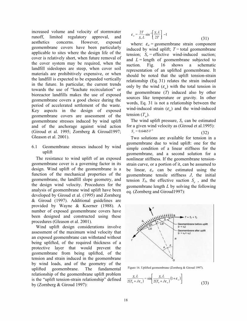
Wind uplift design considerations involveassessment of the maximum wind velocity thatan exposed geomembrane can withstand withoutbeing uplifted, of the required thickness of aprotective layer that would prevent thegeomembrane from being uplifted, of thetension and strain induced in the geomembraneby wind loads, and of the geometry of theuplifted geomembrane. The fundamentalrelationship of the geomembrane uplift problemis the “uplift tension-strain relationship” definedby (Zornberg & Giroud 1997):
12
sin2 1 −
−
T
LSLS
T= e
ewε
(31)where: εw = geomembrane strain component
induced by wind uplift; T = total geomembranetension; Se = effective wind-induced suction;and L = length of geomembrane subjected tosuction. Fig. 16 shows a schematicrepresentation of an uplifted geomembrane. Itshould be noted that the uplift tension-strainrelationship (Eq. 31) relates the strain inducedonly by the wind (εw) with the total tension inthe geomembrane (T) induced also by othersources like temperature or gravity. In otherwords, Eq. 31 is not a relationship between thewind-induced strain (εw) and the wind-inducedtension (Tw).
The wind uplift pressure, Se can be estimatedfor a given wind velocity as (Giroud et al.1995):
26465.0 V=Se (32)Two solutions are available for tension in a
geomembrane due to wind uplift: one for thesimple condition of a linear stiffness for thegeomembrane, and a second solution for anonlinear stiffness. If the geomembrane tension-strain curve, or a portion of it, can be assumed tobe linear, εw can be estimated using thegeomembrane tensile stiffness J, the initialtension T0, the effective suction Se , and thegeomembrane length L by solving the followingeq. (Zornberg and Giroud1997):
( ) ( ) ( )
+
++ ww
e
w
e
JTLS=
JTLS ε
εε1
2sin
2 00 (33)
Figure 16. Uplifted geomembrane (Zornberg & Giroud 1997).
19
The expression above may be solved by trialand error in order to determine εw. Afterdetermining the wind-induced strain component,εw, the tension component induced by wind, Tw ,can also be estimated using the geomembranetensile stiffness J .
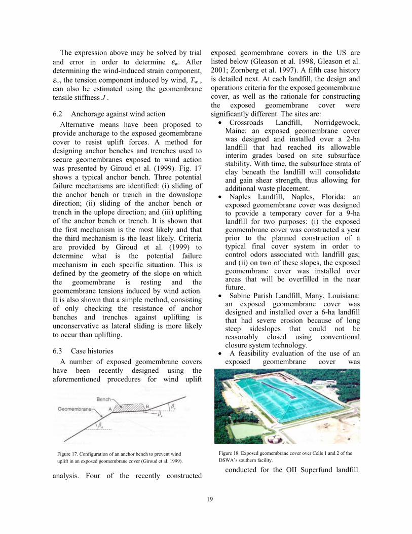
6.2 Anchorage against wind actionAlternative means have been proposed to
provide anchorage to the exposed geomembranecover to resist uplift forces. A method fordesigning anchor benches and trenches used tosecure geomembranes exposed to wind actionwas presented by Giroud et al. (1999). Fig. 17shows a typical anchor bench. Three potentialfailure mechanisms are identified: (i) sliding ofthe anchor bench or trench in the downslopedirection; (ii) sliding of the anchor bench ortrench in the uplope direction; and (iii) upliftingof the anchor bench or trench. It is shown thatthe first mechanism is the most likely and thatthe third mechanism is the least likely. Criteriaare provided by Giroud et al. (1999) todetermine what is the potential failuremechanism in each specific situation. This isdefined by the geometry of the slope on whichthe geomembrane is resting and thegeomembrane tensions induced by wind action.It is also shown that a simple method, consistingof only checking the resistance of anchorbenches and trenches against uplifting isunconservative as lateral sliding is more likelyto occur than uplifting.
6.3 Case historiesA number of exposed geomembrane covers
have been recently designed using theaforementioned procedures for wind uplift
analysis. Four of the recently constructed
exposed geomembrane covers in the US arelisted below (Gleason et al. 1998, Gleason et al.2001; Zornberg et al. 1997). A fifth case historyis detailed next. At each landfill, the design andoperations criteria for the exposed geomembranecover, as well as the rationale for constructingthe exposed geomembrane cover weresignificantly different. The sites are:
• Crossroads Landfill, Norridgewock,Maine: an exposed geomembrane coverwas designed and installed over a 2-halandfill that had reached its allowableinterim grades based on site subsurfacestability. With time, the subsurface strata ofclay beneath the landfill will consolidateand gain shear strength, thus allowing foradditional waste placement.
• Naples Landfill, Naples, Florida: anexposed geomembrane cover was designedto provide a temporary cover for a 9-halandfill for two purposes: (i) the exposedgeomembrane cover was constructed a yearprior to the planned construction of atypical final cover system in order tocontrol odors associated with landfill gas;and (ii) on two of these slopes, the exposedgeomembrane cover was installed overareas that will be overfilled in the nearfuture.
• Sabine Parish Landfill, Many, Louisiana:an exposed geomembrane cover wasdesigned and installed over a 6-ha landfillthat had severe erosion because of longsteep sideslopes that could not bereasonably closed using conventionalclosure system technology.
• A feasibility evaluation of the use of anexposed geomembrane cover was
conducted for the OII Superfund landfill.
Figure 17. Configuration of an anchor bench to prevent winduplift in an exposed geomembrane cover (Giroud et al. 1999).
Figure 18. Exposed geomembrane cover over Cells 1 and 2 of theDSWA’s southern facility.

20
The main reason for having considered anexposed geomembrane cover at this sitewas the difficulty in demonstratingadequate slope stability, under static andseismic conditions, in the case ofconventional covers where geosyntheticsare overlain by soil layers. Although anevapotranspirative cover system was finallyadopted at the site, an exposedgeomembrane cover was also consideredbecause it would have been stable underboth static and seismic conditions.
Delaware Solid Waste Authority (DSWA), Sussex County,Delaware, US
An exposed geomembrane cover wasdesigned and installed over a 17-ha landfill toprovide a long-term cover system (i.e. 10 to 20years) over waste that may be reclaimed at alater date (Gleason et al. 1998). Severalgeomembranes were considered for the designof the exposed cover system. Calculations forthe selected geomembrane involveddetermination of resistance to wind uplift. Areinforced geomembrane with a linear stress-strain curve characterized by a tensile stiffness, J= 165 kN/m and a strain at break of 27% wasselected for the design. The geomembraneanchors on the cover system were designed toinclude a swale that conveys storm-water runofffrom the landfill in a nonerosive manner.
Fig. 18 shows the exposed geomembranecover placed over Cells 1 and 2 at the DSWA’ssouthern facility. This cover was placed over 5%to 4H:1V slopes. The exposed geomembranecover will be removed to allow potential miningof the in-place waste and placement ofadditional waste into the cells. A 0.9 mm greenpolypropylene geomembrane with a polyesterscrim reinforced was used. In this application,the interface friction required of thegeomembrane is defined by the swale anchoragestructure.
7 CONCLUSIONS
This paper focuses on recent advances in theuse of geosynthetics in environmentalapplications. When designing GCL-lined slopesit is essential to recognize the differences in
interface and internal shear strengths. Significanthave been recently compiled, which providegood understanding of the probabilisticdistributions of the peak and large displacementstrength values. These results are suitable forfuture reliability based stability analyses.
Calculating the thickness of liquid in a liquidcollection layer is an important design stepbecause one of the design criteria for a liquidcollection layer is that the maximum thicknessof the liquid collection layer must be less thanan allowable thickness. Simple equations havebeen developed to calculate the maximumthickness of liquid in a liquid collection layer.Such equations are suitable to definetransmissivity requirements of liquid collectionlayers in single and double slopes.
Major advances have recently taken placeregarding the use of geosynthetic reinforcementsto allow significantly steep and high final coversystems. Solutions are presented for the case ofunreinforced, slope-parallel, horizontally-reinforced and fiber-reinforced veneers. Asexpected, additional reinforcement always leadsto a higher factor of safety while increasingslope inclination would typically lead todecreasing stability. Increasing soil frictionangle leads to significant increase in stability,when compared to the unreinforced case, onlyfor the case of fiber reinforced slopes. Increasingtotal height of the slope (or increasing totallength) does not affect detrimentally theefficiency of horizontally placed reinforcementsand of fiber reinforcement.
Exposed geomembrane covers have beenrecently analyzed, designed, and constructed toprovide temporary and final closure to wastecontainment facilities. Key aspects in the designof exposed geomembrane covers are assessmentof the geomembrane stresses induced by winduplift and of the anchorage against wind action.Procedures for the analysis of geomembranewind uplift and methods for designing anchorbenches and trenches used to securegeomembranes exposed to wind action have alsobeen developed. The use of exposedgeomembrane covers is particularly suitable insites with steep landfill slopes and in landfillswhere leachate recirculation is considered.

21
8 REFERENCES
Al Wahab, R.M. & El-Kedrah, M.M. 1995. Usingfibers to reduce tension cracks and shrink/swell incompacted clays. Geoenvironment 2000, ASCEGeot. Sp. Publication 46: 433-446.
Bouazza, M., Zornberg, J.G., and Adam, D. (2002).“Geosynthetics in Waste Containment Facilities:Recent Advances.” Keynote paper, Proc. SeventhIntl. Conf. on Geosynthetics, Nice, France, 22-27September, A.A. Balkema, Vol. 2, pp. 445-510.
Bouazza, A. & Amokrane, K. 1995. Granular soilreinforced with randomly distributed fibres. Proc.11th African Regional Conf. on Soil Mech. &Foundation Eng., Cairo: 207-216.
Bressi, G., Zinessi, M., Montanelli, F. & Rimoldi, P.1995. The slope stability of GCL layers ingeosynthetic lining system. Proc. 5th Intl. Symp.on Landfills, Cagliari 1: 595-610.
Byrne, R.J., Kendall, J. & Brown, S. 1992. Causeand mechanism of failure, Kettleman hills landfillB-19, Unit 1A. Stability and Performance ofSlopes and Embankments, ASCE. Geot. Sp.Publication 31: 1188-1520.
Cancelli, A. & Cazzuffi, D. 1994. Env. aspects ofgeosynthetic applications in landfills and dams.Proc. 5th Intl. Conf. on Geosynthetics, Singapore4: 55-96.
Cargill, K.W. & Olen, K.L. 1998. Landfill closureusing reinforced soil slopes. Proc. 6th Intl. Conf.on Geosynthetics, Atlanta : 481-486.
Cazzuffi, D., 1987. The use of geomembranes inItalian dams. Intl. J. of Water Power and DamConstruction 26(2): 44-52.
Collins, P., Ng, A.S. & Ramanujam, R. 1998.Superfund success, superfast. Civil Eng.,Decembre: 42-45.
Daniel, D. E., Koerner, R., Bonaparte, R., Landreth,R., Carson, D. & Scranton, H. 1998. Slopestability of geosynthetic clay liner test plots. J. ofGeot. and GeoEnv. Eng. 124(7): 628-637.
Eid, H.T & Stark, T.D. 1997. Shear behaviour of anunreinforced geosynthetic clay liner.Geosynthetics Intl. 4(6): 645-659.
Eid, H.T., Stark, T.D. & Doerfler, C.K. 1999. Effectof shear displacement rate on internal shearstrength of a reinforced geosynthetic clay liners.Geosynthetics Intl. 6(3): 219-239.
Feki, N., Garcin, P., Faure, Y.H., Gourc, J.P. &Berroir, G. 1997. Shear strength tests ongeosynthetic clay liner systems. Proc.Geosynthetics 97, Long Beach 2: 899-912.
Foose, G.J., Benson, C.H. & Bosscher, P.J. 1996.Sand reinforced with shredded waste tires. J. ofGeot. Eng. 122 (9): 760-767.
Fox, P. J., Rowland, M.G. & Scheite, J.R. 1998a.Internal shear strength of three geosynthetic clayliners. J. of Geot. and GeoEnv. Eng. 124 (10):933-944.
Frobel, R.K. 1996. Geosynthetic clay liners, partfour: interface and internal shear strengthdetermination. Geot. Fabric Report 14(8): 20-23.
Garcin, P., Faure, Y.H., Gourc, J.P. & Purwanto, E.1995. Behaviour of geosynthetic clay liner (GCL):laboratory tests. Proc. 5th Intl. Symp. on Landfills,Cagliari (1): 347-358.
Gilbert, R.B., Fernandez, F. & Horsfield, D.W. 1996.Shear strength of reinforced GCLs. J. of Geot.Eng. 122 (4): 259-266.
Gilbert, R.B., Liu, C.N., Wright, S.G. & Trautwein,S.J. 1995. A double shear test method formeasuring interface strength. Proc. Geosynthetics95 Conf., Nashville 3: 1017-1029.
Giroud, J.P. & Cazzuffi, D.A. 1989. Uses ofgeosynthetics for Env. control. Proc. of 12th Intl.Conf. on Soil Mech. and Foundation Eng., Rio deJaneiro, Brazil (4): 3119-3125.
Giroud, J.P., Gleason, M.H. & Zornberg, J.G. 1999.Design of geomembrane anchorage against windaction. Geosynthetics Intl. 6(6): 481-507.
Giroud, J.P., Zornberg, J.G. & Zhao, A. 2000a.Hydraulic design of geosynthetic and granularliquid collection Layers. Geosynthetics Intl., Sp.Issue on Liquid Collection Systems 7(4-6): 285-380.
Giroud, J.P., Zornberg, J.G. & Beach, J.F. 2000b.Hydraulic design of geosynthetic and granularliquid collection layers comprising two differentslopes. Geosynthetics Intl., Sp. Issue on LiquidCollection Systems 7(4-6): 453-489.
Giroud, J.P., Zhao, A. & Bonaparte, R. 2000c. Themyth of hydraulic transmissivity equivalencybetween geosynthetic and granular liquidcollection layers. Geosynthetics Intl., Sp. Issue onLiquid Collection Systems 7(4-6): 381-401.
Giroud, J.P., Pelte, T. & Bathurst, R.J., 1995. Upliftof geomembranes by wind. Geosynthetics Intl.,2(6): 897-952.
Giroud, J.P., Williams, N.D., Pelte, T. & Beech, J.F.1995a. Stability of geosynthetic-soil layeredsystems on slopes. Geosynthetics Intl. 2(6): 1115-1148.
Giroud, J.P., Bachus, R.C. & Bonaparte R. 1995b.Influence of water flow on the stability ofgeosynthetic-soil layered systems on slopes.Geosynthetics Intl. 2(6): 1149-1180
Gleason, M.H., Houlihan, M.F. & Palutis, J.R. 2001.Exposed geomembrane cover systems: technologysummary. Proc. Geosynthetics 2001 Conf.,Portland: 905-918.
Gourc, J.P. 1994. Geosynthetics and environmentEng.. The Mercer Lecture. Proc. 13th Intl. Conf.on Soil Mech. and Foundation Eng., New Delhi(4): 65-86.
Gray, D.H. & Al-Refeai, T. 1986. Behaviour offabric versus fiber-reinforced Sand. J. of Geot.Eng. 112(8): 804-820. Gregory, G. H. & Chill, D.S. 1998. Stabilization of earth slopes with fiber-reinforcement. Proc. 6th Intl. Conf. onGeosynthetics, IFAI, Atlanta (2): 1073-1078.
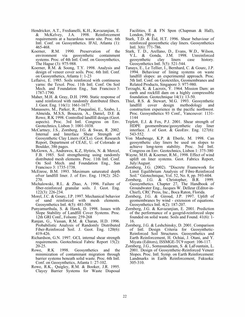
22
Hendricker, A.T., Fredianelli, K.H., Kavazanjian, E.& McKelvey, J.A. 1998. Reinforcementrequirements at a hazardous waste site. Proc. 6thIntl. Conf. on Geosynthetics. IFAI, Atlanta (1):465-468.
Koerner, R.M. 1990. Preservation of theenvironment via geosynthetic containmentsystems. Proc. of 4th Intl. Conf. on Geosynthetics,The Hague (3): 975-988.
Koerner, R.M. & Soong, T.Y. 1998. Analysis anddesign of veneer cover soils. Proc. 6th Intl. Conf.on Geosynthetics, Atlanta 1: 1-23
Leflaive, E. 1985. Soils reinforced with continuousyarns: the Texol. Proc. 11th Intl. Conf. On SoilMech. and Foundation Eng., San Francisco 3:1787-1790.
Maher, M.H. & Gray, D.H. 1990. Static response ofsand reinforced with randomly distributed fibers.J. Geot. Eng. 116(1): 1661-1677.
Manassero, M., Parker, R., Pasqualini, E., Szabo, I.,Almeida, M.S.S, Bouazza, A., Daniel, D.E &Rowe, R.K 1998. Controlled landfill design (Geot.aspects). Proc. 3rd Intl. Congress on Env.Geotechnics, Lisbon 3: 1001-1038.
McCartney, J.S., Zornberg, J.G. & Swan, R. 2002.Internal and Interface Shear Strength ofGeosynthetic Clay Liners (GCLs). Geot. ResearchReport, Department of CEAE, U. of Colorado atBoulder, 386 pages.
McGown, A., Andrawes, K.Z, Hytiris, N. & Mercel,F.B. 1985. Soil strengthening using randomlydistributed mesh elements. Proc. 11th Intl. Conf.On Soil Mech. and Foundation Eng., SanFrancisco 3: 1735-1738.
McEnroe, B.M. 1993. Maximum satureated depthofver landfill liner. J. of Env. Eng. 119(2): 262-270.
Michalowski, R.L. & Zhao, A. 1996. Failure offiber-reinforced granular soils. J. Geot. Eng.122(3): 226-234.
Morel, J.C. & Gourc, J.P. 1997. Mechanical behaviorof sand reinforced with mesh elements.Geosynthetics Intl. 4(5): 481-508.
Punyamurthula, S. & Hawk, D. 1998. Issues withSlope Stability of Landfill Cover Systems. Proc.12th GRI Conf., Folsom: 259-268
Ranjan, G., Vassan, R.M. & Charan, H.D. 1996.Probabilistic Analysis of Randomly DistributedFiber-Reinforced Soil. J. Geot. Eng. 120(6):419-426.
Richardson, G.N. 1997. GCL internal shear strengthrequirements. Geotechnical Fabric Report 15(2):20-25.
Rowe, R.K 1998. Geosynthetics and theminimization of contaminant migration throughbarrier systems beneath solid waste. Proc. 6th Intl.Conf. on Geosynthetics, Atlanta 1: 27-102.
Rowe, R.K., Quigley, R.M. & Booker, J.R. 1995.Clayey Barrier Systems for Waste Disposal
Facilities, E & FN Spon (Chapman & Hall),London, 390 p.
Stark, T.D. & Eid, H.T. 1996. Shear behaviour ofreinforced geosynthetic clay liners. GeosyntheticsIntl. 3(6): 771-786.
Stark, T. D., Arellano, D., Evans, W.D., Wilson,V.L. & Gonda, J.M. 1998. Unreinforcedgeosynthetic clay liners case history.Geosynthetics Intl. 5(5): 521-544.
Tanays, E., Le Tellier, I., Bernhard, C. & Gourc, J.P.1994. Behaviour of lining systems on wastelandfill slopes: an experimental approach. Proc.5th Intl. Conf. on Geotextiles, Geomembranes andRelated Products, Singapore 3: 977-980.
Terzaghi, K. & Lacroix, Y. 1964. Mission Dam: anearth and rockfill dam on a highly compressiblefoundation. Geotechnique 14(1): 13-50.
Thiel, R.S. & Stewart, M.G. 1993. Geosyntheticlandfill cover design methodology andconstruction experience in the pacific northwest.Proc. Geosynthetics 93 Conf., Vancouver: 1131-1144
Triplett, E.J. & Fox, P.J. 2001. Shear strength ofHDPE geomembrane/geosynthetic clay linerinterface. J. of Geot. & GeoEnv. Eng. 127(6):543-552.
Von Maubeuge, K.P. & Eberle, M. 1998. Cangeosynthetic clay liners be used on slopes toachieve long-term stability. Proc. 3rd Intl.Congress on Env. Geotechnics, Lisbon 1: 375-380
Wayne, M.H. & Koerner, R.M., 1998. Effect of winduplift on liner systems. Geot. Fabrics Report,July/August.
Zornberg, J.G. (2002). “Discrete Framework forLimit Equilibrium Analysis of Fibre-ReinforcedSoil.” Géotechnique, Vol. 52, No. 8, pp. 593-604.
Zornberg, J.G. & Christopher, B.R. 1999.Geosynthetics. Chapter 27, The Handbook ofGroundwater Eng., Jacques W. Delleur (Editor-in-Chief), CRC Press, Inc., Boca Raton, Florida.
Zornberg, J.G. & Giroud, J.P. 1997. Uplift ofgeomembranes by wind - extension of equations.Geosynthetics Intl. 4(2): 187-207.
Zornberg, J.G. & Kavazanjian, E. 2001. Predictionof the performance of a geogrid-reinforced slopefounded on solid waste. Soils and Found. 41(6): 1-16.
Zornberg, J.G. & Leshchinsky, D. 2001. Comparisonof Intl. Design Criteria for Geosynthetic-Reinforced Soil Structures. Geosynthetics andEarth Reinforcement, H. Ochiai, J. Otani, and Y.Miyata (Editors), ISSMGE-TC9 report: 106-117.
Zornberg, J.G., Somasundaram, S. & LaFountain, L.2001. Design of Geosynthetic-Reinforced VeneerSlopes. Proc. Intl. Symp. on Earth Reinforcement:Landmarks in Earth Reinforcement, Fukuoka:305-310.