Embed Size (px)
Citation preview

Zornberg, Jorge G. et al.“Geosynthetics” The Handbook of Groundwater Engineering Editor-in-Chief Jacques W. DelleurBoca Raton: CRC Press LLC,1999
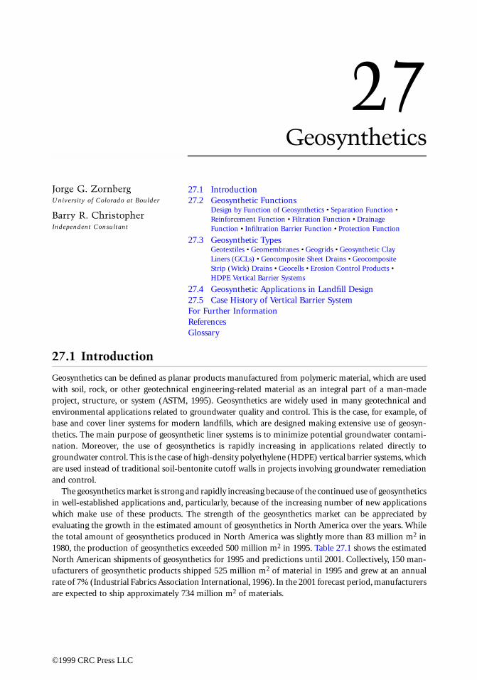
27Geosynthetics
27.1 Introduction27.2 Geosynthetic Functions
Design by Function of Geosynthetics • Separation Function • Reinforcement Function • Filtration Function • Drainage Function • Infiltration Barrier Function • Protection Function
27.3 Geosynthetic TypesGeotextiles • Geomembranes • Geogrids • Geosynthetic Clay Liners (GCLs) • Geocomposite Sheet Drains • Geocomposite Strip (Wick) Drains • Geocells • Erosion Control Products • HDPE Vertical Barrier Systems
27.4 Geosynthetic Applications in Landfill Design27.5 Case History of Vertical Barrier SystemFor Further InformationReferencesGlossary
27.1 Introduction
Geosynthetics can be defined as planar products manufactured from polymeric material, which are usedwith soil, rock, or other geotechnical engineering-related material as an integral part of a man-madeproject, structure, or system (ASTM, 1995). Geosynthetics are widely used in many geotechnical andenvironmental applications related to groundwater quality and control. This is the case, for example, ofbase and cover liner systems for modern landfills, which are designed making extensive use of geosyn-thetics. The main purpose of geosynthetic liner systems is to minimize potential groundwater contami-nation. Moreover, the use of geosynthetics is rapidly increasing in applications related directly togroundwater control. This is the case of high-density polyethylene (HDPE) vertical barrier systems, whichare used instead of traditional soil-bentonite cutoff walls in projects involving groundwater remediationand control.
The geosynthetics market is strong and rapidly increasing because of the continued use of geosyntheticsin well-established applications and, particularly, because of the increasing number of new applicationswhich make use of these products. The strength of the geosynthetics market can be appreciated byevaluating the growth in the estimated amount of geosynthetics in North America over the years. Whilethe total amount of geosynthetics produced in North America was slightly more than 83 million m2 in1980, the production of geosynthetics exceeded 500 million m2 in 1995. Table 27.1 shows the estimatedNorth American shipments of geosynthetics for 1995 and predictions until 2001. Collectively, 150 man-ufacturers of geosynthetic products shipped 525 million m2 of material in 1995 and grew at an annualrate of 7% (Industrial Fabrics Association International, 1996). In the 2001 forecast period, manufacturersare expected to ship approximately 734 million m2 of materials.
Jorge G. ZornbergUniversity of Colorado at Boulder
Barry R. ChristopherIndependent Consultant
©1999 CRC Press LLC

Geosynthetics applications are very diverse. In order to fulfill different functions in the design ofgeotechnical-, environmental-, and groundwater-related systems, the geosynthetic industry has developeda number of products. In addition to the already mentioned examples regarding use of geomembranesin landfill liner systems and the use of HDPE vertical panels in groundwater control projects, otherexamples of geosynthetics applications include the use of geotextiles as filtration elements in dams andwaste containment systems, the use of geocomposites as erosion control elements in channels and slopes,and the use of geogrids as reinforcement elements in soil embankments, to mention a few more.
Geosynthetics have numerous material properties. Many of the reported properties are important inthe manufacture and quality control of geosynthetics; however, many others are also important in design.The material properties related to the manufacture and quality control of geosynthetics are generallyreferred to as index properties and those related to the design as design or performance properties.Considering their different properties, the several geosynthetic products can perform different functionsand, consequently, they should be designed to satisfy minimum criteria to adequately perform thesefunctions. The different functions performed by geosynthetics are discussed in Section 27.2. The geo-synthetic functions are as follows:
• Separation
• Reinforcement
• Filtration
• Drainage
• Infiltration barrier
• Protection (or stress relief)
Geosynthetics are manufactured in a factory-controlled environment. They are packaged in sheets,placed in a roll or carton, and finally transported to the site. At the project site the geosynthetic sheetsare unrolled on the prepared subgrade surface, overlapped to each other to form a continuous geosyn-thetic blanket, and often physically joined to each other. The individual types of products within thegeosynthetics family are discussed in Section 27.3. The geosynthetic types are as follows:
• Geotextiles
• Geomembranes
• Geogrids
• Geosynthetic clay liners (GCLs)
• Geocomposite sheet drains
• Geocomposite strip (wick) drains
• Geocells
• Erosion control products
• HDPE vertical barrier systems
TABLE 27.1 North American Shipments of Geosynthetic Materials, 1995-2001 (In Million m2)
1995 1996 1998 2001
Geotextiles 346.2 356.2 419.7 477.4Geomembranes 62.4 64.4 74.6 86.8Geogrids 22.9 24.3 29.1 36.8Geosynthetic clay liners 5.0 5.4 6.1 8.2Erosion-control products 72.7 77.8 82.8 93.6Specialty geosynthetics 16.7 20.1 25.9 31.8
From Industrial Fabrics Association International. 1996. North American Market for Geosynthetics — 1996.
©1999 CRC Press LLC
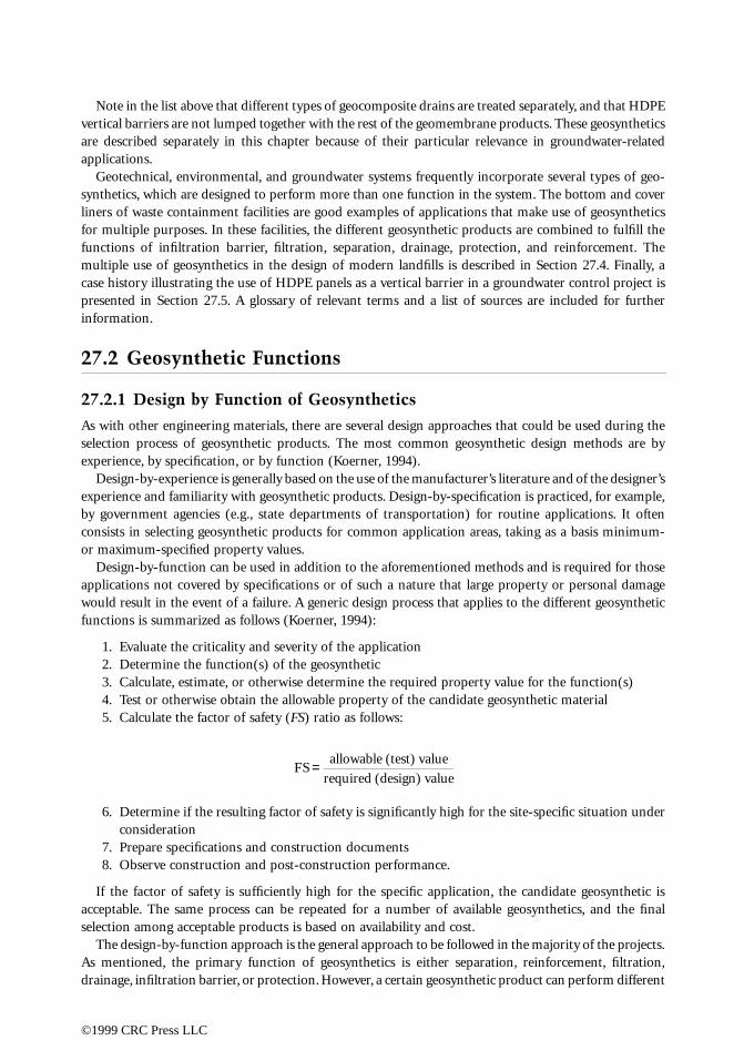
Note in the list above that different types of geocomposite drains are treated separately, and that HDPEvertical barriers are not lumped together with the rest of the geomembrane products. These geosyntheticsare described separately in this chapter because of their particular relevance in groundwater-relatedapplications.
Geotechnical, environmental, and groundwater systems frequently incorporate several types of geo-synthetics, which are designed to perform more than one function in the system. The bottom and coverliners of waste containment facilities are good examples of applications that make use of geosyntheticsfor multiple purposes. In these facilities, the different geosynthetic products are combined to fulfill thefunctions of infiltration barrier, filtration, separation, drainage, protection, and reinforcement. Themultiple use of geosynthetics in the design of modern landfills is described in Section 27.4. Finally, acase history illustrating the use of HDPE panels as a vertical barrier in a groundwater control project ispresented in Section 27.5. A glossary of relevant terms and a list of sources are included for furtherinformation.
27.2 Geosynthetic Functions
27.2.1 Design by Function of Geosynthetics
As with other engineering materials, there are several design approaches that could be used during theselection process of geosynthetic products. The most common geosynthetic design methods are byexperience, by specification, or by function (Koerner, 1994).
Design-by-experience is generally based on the use of the manufacturer’s literature and of the designer’sexperience and familiarity with geosynthetic products. Design-by-specification is practiced, for example,by government agencies (e.g., state departments of transportation) for routine applications. It oftenconsists in selecting geosynthetic products for common application areas, taking as a basis minimum-or maximum-specified property values.
Design-by-function can be used in addition to the aforementioned methods and is required for thoseapplications not covered by specifications or of such a nature that large property or personal damagewould result in the event of a failure. A generic design process that applies to the different geosyntheticfunctions is summarized as follows (Koerner, 1994):
1. Evaluate the criticality and severity of the application2. Determine the function(s) of the geosynthetic3. Calculate, estimate, or otherwise determine the required property value for the function(s)4. Test or otherwise obtain the allowable property of the candidate geosynthetic material5. Calculate the factor of safety (FS) ratio as follows:
6. Determine if the resulting factor of safety is significantly high for the site-specific situation underconsideration
7. Prepare specifications and construction documents8. Observe construction and post-construction performance.
If the factor of safety is sufficiently high for the specific application, the candidate geosynthetic isacceptable. The same process can be repeated for a number of available geosynthetics, and the finalselection among acceptable products is based on availability and cost.
The design-by-function approach is the general approach to be followed in the majority of the projects.As mentioned, the primary function of geosynthetics is either separation, reinforcement, filtration,drainage, infiltration barrier, or protection. However, a certain geosynthetic product can perform different
FS
allowable (test) value
required (design) value=
©1999 CRC Press LLC

functions and, similarly, the same function can often be performed by different types of geosynthetics.The specific function(s) of the different geosynthetic(s) are presented in Table 27.2. Each of thesefunctions is described in Sections 27.2.2 to 27.2.7.
27.2.2 Separation Function
Separation is the introduction of a flexible, porous geosynthetic product between dissimilar materials sothat the integrity and functioning of both materials can remain intact or be improved. For example, amajor cause of failure of roadways constructed over soft foundations is contamination of the aggregatebase courses with the underlying soft subgrade soils (Figure 27.1A). Contamination occurs due to: (1)penetration of the aggregate into the weak subgrade due to localized bearing capacity failure under stressesinduced by wheel loads, and (2) inclusion of fine-grained soils into the aggregate because of pumpingor subgrade weakening due to excess pore water pressures. Subgrade contamination results in inadequatestructural support, which often leads to premature failure of the system. A geotextile can be placedbetween the aggregate and the subgrade to act as a separator and prevent the subgrade and aggregatebase course from mixing (Figure 27.1B).
Among the different geosynthetics, geotextiles have been the products generally used in the functionof separation. Examples of separation applications are the use of geotextiles between subgrade and stonebase in roads and airfields, and between geomembranes and drainage layers in landfills. In addition tothese applications, in which separation is the primary function of the geotextile, it could be said thatmost geosynthetics generally include separation as a secondary function.
Geosynthetics used as erosion control systems can also be considered as performing a separationfunction. In this case, the geosynthetic separates the ground surface from the prevailing atmospheric
TABLE 27.2 Function of Different Geosynthetic Products
Geo-textile
Geo-membrane
Geo-grid GCL
Geo-composite
Sheet Drain
Geo-composite
Strip (Wick)Drain Geocell
Erosion Control Product
HDPE Vertical Barrier
Separation X X XReinforcement X X XFiltration XDrainage X X XInfiltration barrier X1 X X XProtection X X
1 Asphalt-saturated geotextiles
FIGURE 27.1 Separation function of a geotextile placed between road aggregate and soft subgrade.
©1999 CRC Press LLC
©1999 CRC Press
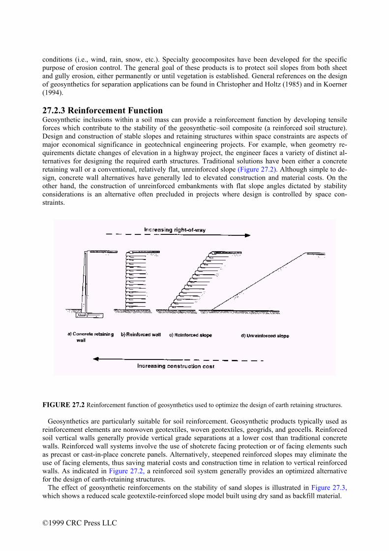
conditions (i.e., wind, rain, snow, etc.). Specialty geocomposites have been developed for the specific purpose of erosion control. The general goal of these products is to protect soil slopes from both sheet and gully erosion, either permanently or until vegetation is established. General references on the design of geosynthetics for separation applications can be found in Christopher and Holtz (1985) and in Koerner (1994). 27.2.3 Reinforcement Function Geosynthetic inclusforces which contribDesign and construcmajor economical squirements dictate cternatives for designretaining wall or a csign, concrete wall other hand, the conconsiderations is anstraints.
FIGURE 27.2 Reinf Geosynthetics are reinforcement elemesoil vertical walls gwalls. Reinforced was precast or cast-inuse of facing elemenwalls. As indicated for the design of ear The effect of geoswhich shows a reduc
LLC
ions within a soil mass can provide a reinforcement function by developing tensile ute to the stability of the geosynthetic–soil composite (a reinforced soil structure). tion of stable slopes and retaining structures within space constraints are aspects of ignificance in geotechnical engineering projects. For example, when geometry re-hanges of elevation in a highway project, the engineer faces a variety of distinct al-ing the required earth structures. Traditional solutions have been either a concrete
onventional, relatively flat, unreinforced slope (Figure 27.2). Although simple to de-alternatives have generally led to elevated construction and material costs. On the struction of unreinforced embankments with flat slope angles dictated by stability alternative often precluded in projects where design is controlled by space con-
orcement function of geosynthetics used to optimize the design of earth retaining structures.
particularly suitable for soil reinforcement. Geosynthetic products typically used as nts are nonwoven geotextiles, woven geotextiles, geogrids, and geocells. Reinforced enerally provide vertical grade separations at a lower cost than traditional concrete all systems involve the use of shotcrete facing protection or of facing elements such -place concrete panels. Alternatively, steepened reinforced slopes may eliminate the ts, thus saving material costs and construction time in relation to vertical reinforced
in Figure 27.2, a reinforced soil system generally provides an optimized alternative th-retaining structures. ynthetic reinforcements on the stability of sand slopes is illustrated in Figure 27.3, ed scale geotextile-reinforced slope model built using dry sand as backfill material.

The maximum slope inclination of an unreinforced sand under its own weight is the angle of repose ofthe sand, which is well below the inclination of the slope face of the model. Horizontal geotextilereinforcements placed within the backfill provided stability to the steep sand slope. In fact, not only didthe reinforced slope model not fail under its own weight, but its failure only occurred after the unitweight of the backfill was increased 67 times by placing the model in a geotechnical centrifuge (Zornberget al., 1997). Figure 27.4 shows the reinforced slope model after centrifuge testing.
The use of inclusions to improve the mechanical properties of soils dates to ancient times. However,it is only within the last quarter of century or so (Vidal, 1969) that analytical and experimental studieshave led to contemporary soil reinforcement techniques. Soil reinforcement is now a highly attractivealternative for embankment and retaining wall projects because of the economic benefits it offers inrelation to conventional retaining structures. Moreover, its acceptance has also been triggered by a number
FIGURE 27.3 Model of a sand slope reinforced with geosynthetics.
FIGURE 27.4 Reinforced slope model brought to failure by increasing the unit weight of the backfill.
©1999 CRC Press LLC
of technical factors, that include aesthetics, reliability, simple construction techniques, good seismicperformance, and the ability to tolerate large deformations without structural distress. The design ofreinforced soil slopes is based on the use of limit equilibrium methods to evaluate both external (global)and internal stability of the structure. The required tensile strength of the reinforcements is selectedduring design so that the margins of safety, considering an internal failure similar to the one shown inFigure 27.4, are adequate. Guidance in soil reinforcement design procedures is provided by Mitchell andVillet (1987), Christopher et al. (1989), and Elias and Christopher (1997).
27.2.4 Filtration Function
The filtration function involves movement of liquid through the geosynthetic and, at the same time,retention of soil on its upstream side. As indicated in Table 27.2, geotextiles are the geosynthetic productgenerally used in filtration. Both adequate hydraulic conductivity (provided by a geotextile with arelatively open structure) and adequate soil retention (provided by a geotextile with a relatively tightstructure) should be offered by the selected product. In addition, considerations should be made regardingthe long-term soil-to-geotextile flow compatibility such that the flow through the geotextile will notreduce excessively by clogging during the lifetime of the system. The geosynthetic-to-soil system shouldthen achieve an equilibrium that allows for adequate liquid flow with limited soil loss across the planeof the geotextile over a service lifetime compatible with the application under consideration. Filtrationconcepts are well established in the design of soil filters, and similar concepts can be used in the designof geotextile filters.
The flow of liquid is perpendicular to the plane of the geosynthetic and, consequently, filtration refersto the cross-plane hydraulic conductivity. Some of the geosynthetics used for this purpose are relativelythick and compressible. For this reason, geosynthetics are generally characterized by their permittivity,which is defined as:
ψ = kn/t
where ψ is the permittivity, kn is the cross-plane hydraulic conductivity, and t is the geosynthetic thicknessat a specified normal pressure.
Testing procedures for geotextile permittivity follow similar guidelines used for testing soil hydraulicconductivity. Some designers prefer to work directly with hydraulic conductivity and require the geotextilehydraulic conductivity to be some multiple of the adjacent soil’s hydraulic conductivity (Christopher andFischer, 1992).
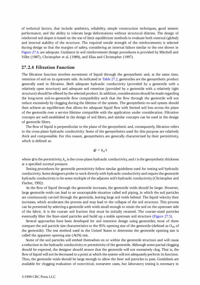
As the flow of liquid through the geotextile increases, the geotextile voids should be larger. However,large geotextile voids can lead to an unacceptable situation called soil piping, in which the soil particlesare continuously carried through the geotextile, leaving large soil voids behind. The liquid velocity thenincreases, which accelerates the process and may lead to the collapse of the soil structure. This processcan be prevented by selecting a geotextile with voids small enough to retain the soil on the upstream sideof the fabric. It is the coarser soil fraction that must be initially retained. The coarser-sized particleseventually filter the finer-sized particles and build up a stable upstream soil structure (Figure 27.5).
Several approaches have been developed for soil retention design using geotextiles; most of themcompare the soil particle size characteristics to the 95% opening size of the geotextile (defined as O95 ofthe geotextile). The test method used in the United States to determine the geotextile opening size iscalled the apparent opening size (AOS) test.
Some of the soil particles will embed themselves on or within the geotextile structure and will causea reduction in the hydraulic conductivity or permittivity of the geotextile. Although some partial cloggingshould be expected, the designer should ensure that the geotextile will not excessively clog. That is, theflow of liquid will not be decreased to a point at which the system will not adequately perform its function.Thus, the geotextile voids should be large enough to allow the finer soil particles to pass. Guidelines areavailable for clogging evaluation of noncritical, nonsevere cases, but laboratory testing is necessary in
©1999 CRC Press LLC
important applications. Either the gradient ratio test (Haliburton and Wood, 1982), the long-term flowtest (Halse et al., 1987), or the hydraulic conductivity ratio test (Williams and Abouzakhm, 1989) shouldbe performed. An evaluation of the filtration function of geotextiles is provided by Christopher andFischer (1992), Giroud (1996), Bhatia and Smith (1996a,b), Bhatia et al. (1996), and Holtz et al. (1997).
27.2.5 Drainage Function
Geosynthetics provide a drainage function by transmitting liquid within the plane of their structure. Asshown in Table 27.2, the geosynthetics generally used for drainage purposes are geotextiles and geocom-posites. The drainage function of geosynthetics allows for adequate liquid flow with limited soil losswithin the plane of the geotextile over a service lifetime compatible with the application under consid-eration.
Thick, needle-punched nonwoven geotextiles have considerable void space in their structure and canconvey large amounts of liquid. Geocomposite drains can transmit one to two orders of magnitude moreliquid than geotextiles. Proper design should dictate what type of geosynthetic drainage material isnecessary.
Except for the consideration of flow direction, the soil retention and the long-term compatibilityconsiderations regarding the drainage function of geosynthetics are the same as those discussed in Section27.2.4 regarding the filtration function of geosynthetics. Since the geosynthetic thickness decreases withincreasing normal stress, the in-plane drainage of a geosynthetic is generally quantified by its transmis-sivity, which is defined as:
θ = kp · t
where θ is the transmissivity, kp is the in-plane hydraulic conductivity, and t is the geosynthetic thicknessat a specified normal pressure.
The geotextile, either when used as a drain itself or when placed onto a core to form a geocompositemust fulfill the filtration function. The compatibility of the soil with the geotextile filter must be ensuredover the lifetime of the system being built. General references on design methods for the use of geosyn-thetics for drainage applications can be found in Holtz et al. (1997) and in Koerner (1994).
FIGURE 27.5 Geotextile providing adequate filtration through selection of adequate opening size.
©1999 CRC Press LLC
27.2.6 Infiltration Barrier Function
The infiltration barrier function can be performed by geosynthetic products that have hydraulic conduc-tivity low enough to provide containment to liquid or vapor. As shown in Table 27.2, the infiltrationbarrier function may be provided by several types of geosynthetics, namely, geomembranes and geosyn-thetic clay liners (GCLs). Other geosynthetic products also used as infiltration barriers include mem-brane-encapsulated soil layers (MESLs) used with paved or unpaved road construction, asphalt-saturatedgeotextiles used in the prevention of bituminous pavement crack reflection problems, and geofoam usedfor insulation against moisture and/or temperature.
Geosynthetic barriers are commonly used as liners for surface impoundments storing hazardous andnonhazardous liquids, as covers above the liquid surface of storage reservoirs, and as liners for canalsused to convey water or chemicals. Geosynthetic barriers are also used as secondary containment forunderground storage tanks and in applications related to dams and tunnels. Of particular relevance forgroundwater applications is the use of geosynthetic barriers for seepage control (HDPE vertical barriersystems). A common application of geosynthetics as infiltration barriers is for base and cover liner systemsof landfills. In landfill applications, infiltration barriers are typically used instead of or in addition tolow-hydraulic conductivity soils. Base liners are placed below the waste to prevent liquids from the landfill(leachate) from contaminating the underlying ground and the groundwater. Geosynthetic cover linersystems are placed above the final waste configuration to keep precipitation water from entering the wasteand generate leachate. If a building or other structure is constructed on a landfill, a geosynthetic barriermay be placed under the building foundation to provide a barrier for vapors such as landfill gas. Theuse of geosynthetics in infiltration barriers is further described in Koerner (1994).
27.2.7 Protection Function
Geosynthetics (mainly geotextiles) can be used to protect other geosynthetics (mainly geomembranes)against damage. A common example is the use of geotextiles to provide protection against puncture ofgeomembranes in waste and liquid containment systems. Adequate mechanical protection must beprovided to resist both short-term equipment loads and long-term loads imparted by the waste. Expe-rience has shown that geotextiles can play an important role in the successful installation and longer-term performance of geomembranes by acting as a cushion to prevent puncture damage of the geomem-brane. In the case of landfill base liners, geotextiles can be placed (1) below the geomembrane to resistpuncture and wear due to abrasion caused by sharp-edged rocks in the subgrade, and (2) above thegeomembrane to resist puncture caused either by the drainage aggregate or direct contact with wastematerials. Likewise, in the case of landfill cover liners, geotextiles can be placed below the geomembraneto reduce risk of damage by sharp objects in the landfill and above the geomembrane to prevent damageduring placement of drainage aggregate or cover soil. Key characteristics for the geotextile cushions arepolymer type, mass density, method of manufacture, and construction survivability. The selection processof a geotextile that fulfills a protective function of a geomembrane involves the following three steps: (1)selection of polymer type and method of manufacture; (2) evaluation of the geotextile’s capacity toprovide puncture protection for the geomembrane; and (3) evaluation of construction survivability.Detailed procedures and methods for conducting these evaluations are described by Holtz et al. (1997),Koerner et al. (1996), Narejo et al. (1996), and Wilson-Fahmy et al. (1996).
27.3 Geosynthetic Types
27.3.1 Geotextiles
Among the different geosynthetic products, geotextiles are the ones that present the widest range ofproperties. They can be used to fulfill all the different functions listed in Table 27.2 for many differentgeotechnical, environmental, and groundwater applications. For example, Figure 27.6 shows the con-
©1999 CRC Press LLC

struction of a reinforced slope in which geotextiles were selected as multipurpose inclusions within thefill, because they can provide not only the required tensile strength (reinforcement function), but alsothe required transmissivity (drainage function) needed for that particular project (Zornberg et al., 1996).
Geotextiles are manufactured from polymer fibers or filaments which are later formed to develop thefinal product. Approximately 75% of the geotextiles used today are based on polypropylene resin. Anadditional 20% are polyester, and the remaining 5% is a range of polymers including polyethylene, nylon,and other resins used for specialty purposes. As with all geosynthetics, however, the base resin has variousadditives, such as for ultraviolet light protection.
The most common types of fibers used in the manufacture of geotextiles are monofilament, staple,and slit-film. If fibers are twisted or spun together, they are known as a yarn. Monofilament fibers arecreated by extruding the molten polymer through an apparatus containing small-diameter holes. Theextruded polymer strings are then cooled and stretched to give the fiber increased strength. Staple fibersare also manufactured by extruding the molten polymer; however, the extruded strings are cut into 25-to 100-mm portions. The staple fibers may then be spun into longer fibers known as staple yarns. Slit-film fibers are manufactured by either extruding or blowing a film of a continuous sheet of polymer andcutting it into fibers by knives or lanced air jets. Slit-film fibers have a flat, rectangular cross-sectioninstead of the circular cross-section shown by the monofilament and staple fibers.
The fibers or yarns are formed into geotextiles using either woven or nonwoven methods. Figure 27.7shows a number of typical woven and nonwoven geotextiles. Woven geotextiles are manufactured usingtraditional weaving methods and a variety of weave types. Nonwoven geotextiles are manufactured byplacing and orienting the fabrics on a conveyor belt and subsequently bonding them by needle punchingor melt bonding. The needle-punching process consists of pushing numerous barbed needles throughthe fiber web. The fibers are thus mechanically interlocked into a stable configuration. As the nameimplies, the heat (or melt) bonding process consists of melting and pressurizing the fibers together.
Common terminology associated with geotextiles includes machine direction, cross machine direction,and selvage. Machine direction refers to the direction in the plane of fabric in line with the direction ofmanufacture. Conversely, cross machine direction refers to the direction in the plane of fabric perpen-dicular to the direction of manufacture. The selvage is the finished area on the sides of the geotextile
FIGURE 27.6 Placement of a high-strength nonwoven geotextile to perform a dual function of reinforcement andin-plane drainage in a reinforced slope.
©1999 CRC Press LLC
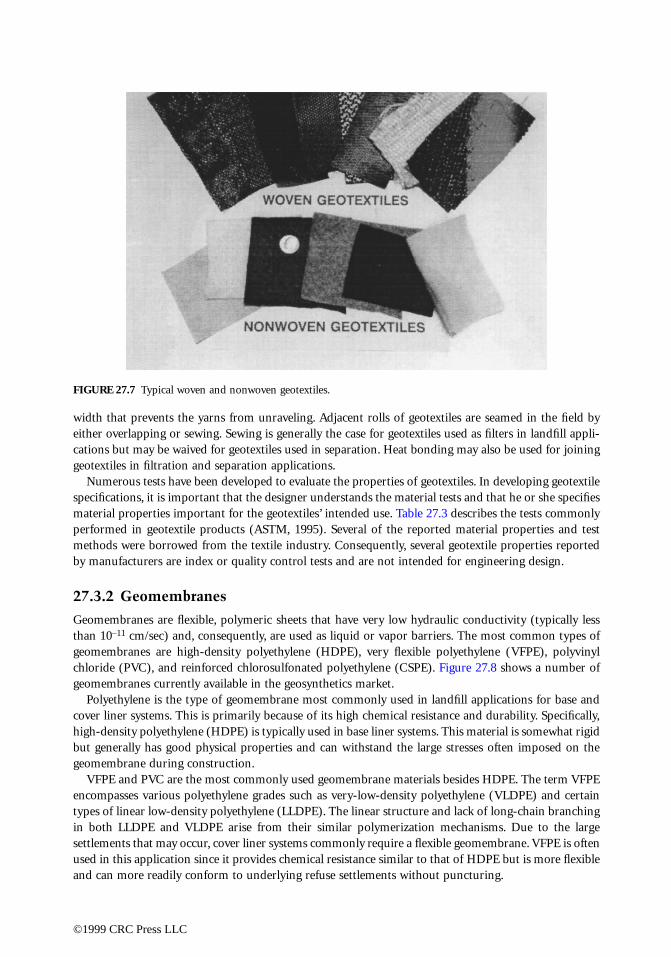
width that prevents the yarns from unraveling. Adjacent rolls of geotextiles are seamed in the field byeither overlapping or sewing. Sewing is generally the case for geotextiles used as filters in landfill appli-cations but may be waived for geotextiles used in separation. Heat bonding may also be used for joininggeotextiles in filtration and separation applications.
Numerous tests have been developed to evaluate the properties of geotextiles. In developing geotextilespecifications, it is important that the designer understands the material tests and that he or she specifiesmaterial properties important for the geotextiles’ intended use. Table 27.3 describes the tests commonlyperformed in geotextile products (ASTM, 1995). Several of the reported material properties and testmethods were borrowed from the textile industry. Consequently, several geotextile properties reportedby manufacturers are index or quality control tests and are not intended for engineering design.
27.3.2 Geomembranes
Geomembranes are flexible, polymeric sheets that have very low hydraulic conductivity (typically lessthan 10–11 cm/sec) and, consequently, are used as liquid or vapor barriers. The most common types ofgeomembranes are high-density polyethylene (HDPE), very flexible polyethylene (VFPE), polyvinylchloride (PVC), and reinforced chlorosulfonated polyethylene (CSPE). Figure 27.8 shows a number ofgeomembranes currently available in the geosynthetics market.
Polyethylene is the type of geomembrane most commonly used in landfill applications for base andcover liner systems. This is primarily because of its high chemical resistance and durability. Specifically,high-density polyethylene (HDPE) is typically used in base liner systems. This material is somewhat rigidbut generally has good physical properties and can withstand the large stresses often imposed on thegeomembrane during construction.
VFPE and PVC are the most commonly used geomembrane materials besides HDPE. The term VFPEencompasses various polyethylene grades such as very-low-density polyethylene (VLDPE) and certaintypes of linear low-density polyethylene (LLDPE). The linear structure and lack of long-chain branchingin both LLDPE and VLDPE arise from their similar polymerization mechanisms. Due to the largesettlements that may occur, cover liner systems commonly require a flexible geomembrane. VFPE is oftenused in this application since it provides chemical resistance similar to that of HDPE but is more flexibleand can more readily conform to underlying refuse settlements without puncturing.
FIGURE 27.7 Typical woven and nonwoven geotextiles.
©1999 CRC Press LLC
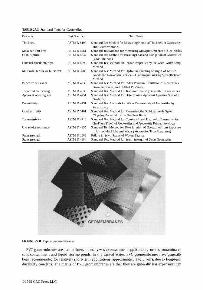
PVC geomembranes are used in liners for many waste containment applications, such as contaminatedsoils containment and liquid storage ponds. In the United States, PVC geomembranes have generallybeen recommended for relatively short-term applications, approximately 1 to 5 years, due to long-termdurability concerns. The merits of PVC geomembranes are that they are generally less expensive than
TABLE 27.3 Standard Tests for Geotextiles
Property Test Standard Test Name
Thickness ASTM D 5199 Standard Test Method for Measuring Nominal Thickness of Geotextiles and Geomembranes
Mass per unit area ASTM D 5261 Standard Test Method for Measuring Mass per Unit area of GeotextilesGrab rupture ASTM D 4632 Standard Test Method for Breaking Load and Elongation of Geotextiles
(Grab Method)Uniaxial tensile strength ASTM D 4595 Standard Test Method for Tensile Properties by the Wide-Width Strip
MethodMultiaxial tensile or burst tests ASTM D 3786 Standard Test Method for Hydraulic Bursting Strength of Knitted
Goods and Nonwoven Fabrics — Diaphragm Bursting Strength Tester Method
Puncture resistance ASTM D 4833 Standard Test Method for Index Puncture Resistance of Geotextiles, Geomembranes, and Related Products.
Trapezoid tear strength ASTM D 4533 Standard Test Method for Trapezoid Tearing Strength of GeotextilesApparent opening size ASTM D 4751 Standard Test Method for Determining Apparent Opening Size of a
GeotextilePermittivity ASTM D 4491 Standard Test Methods for Water Permeability of Geotextiles by
PermittivityGradient ratio ASTM D 5101 Standard Test Method for Measuring the Soil-Geotextile System
Clogging Potential by the Gradient RatioTransmissivity ASTM D 4716 Standard Test Method for Constant Head Hydraulic Transmissivity
(In-Plane Flow) of Geotextiles and Geotextile Related ProductsUltraviolet resistance ASTM D 4355 Standard Test Method for Deterioration of Geotextiles from Exposure
to Ultraviolet Light and Water (Xenon-Arc Type Apparatus)Seam strength ASTM D 1683 Failure in Sewn Seams of Woven FabricsSeam strength ASTM D 4884 Standard Test Method for Seam Strength of Sewn Geotextiles
FIGURE 27.8 Typical geomembranes.
©1999 CRC Press LLC

polyethylene geomembrane and can be factory manufactured in relatively large panels. The large panelsizes allow easier installation since there are fewer field fabricated seams.
In landfill applications, geomembranes are typically used as a base or a cover liner in place of or inaddition to low-hydraulic conductivity soils. The key performance factors related to the selection ofgeomembrane polymer types for landfill applications are summarized in Table 27.4. Geomembranethickness ranges from 0.75 to 2.5 mm (30 to 100 mils). Table 27.5 summarizes the key performancefactors related to the selection of the thickness of HDPE geomembranes for landfill applications.Geomembranes are placed after subgrade preparation, and placement is followed by seaming, inspection,and backfilling. A properly designed geomembrane has the potential of hundreds of years of servicelifetime, but installation must follow high-quality management principles. In the early uses of geomem-branes for waste containment applications, the main concerns were related to the chemical compatibilitybetween geomembranes and waste, and to the service life of geomembranes. Now, construction qualityissues are viewed as the principal limitations to the performance of geomembranes.
For continuity of the impermeable barrier, geomembranes should be seamed in the field. The funda-mental mechanism of seaming polymeric geomembrane sheets together is to temporarily reorganize(melt) the polymer structure of the two surfaces to be joined in a controlled manner. This reorganizationcan be done either through thermal or chemical processes. These processes may involve the addition ofextra polymer in the bonded area. There are four general categories of seaming methods: extrusionwelding, thermal fusion or melt bonding, chemical fusion, and adhesive seaming. Extrusion welding andthermal fusion are the methods most commonly used, and are described next.
TABLE 27.4 Criteria for Selection of HDPE, PVC, or CSPE Geomembranes
Criteria Considerations for Selection
Liquid barrier All three polymers have acceptable characteristics as liquid barriers, although HDPE geomembranes have the best. All three have extremely low hydraulic conductivity and are impermeable for practical purposes.
Mechanical properties Although the mechanical properties vary somewhat with geomembrane thickness, HDPE is relatively stiff and has relatively small yield strain. PVC, in contrast, is relatively extensible and does not exhibit yield. The tensile properties of CSPE often fall between those of HDPE and PVC but are difficult to generalize because CSPE is often made with embedded reinforcing fabrics which affect tensile response.
Construction survivability All three polymers have acceptable ability to maintain integrity when subjected to concentrated stresses. However, the best performance is obtained with more extensible geomembranes. Therefore, based on the relative extensibility, PVC offers the most favorable performance.
Installation Key considerations include ease of placement and seaming. PVC and CSPE are easier to place than HDPE because their greater flexibility makes them conform more easily to the foundation and makes them less prone to thermal expansion wrinkles. Acceptable placement and wrinkle control, however, can be achieved with all three polymers if appropriate installation procedures are used. All three polymers are easily seamed, with HDPE usually achieving the highest seam strength and quality.
Chemical resistance HDPE has the highest degree of compatibility with a wide variety of chemicals encountered in wastes. CSPE has good resistance to many chemicals but is attacked by some which are relatively common, namely chlorinated solvents and hydrocarbons. PVC typically is the least chemically resistant of the three polymers.
Long-term durability HDPE offers the best performance. HDPE is a highly inert and durable material that is not susceptible to chemical degradation under conditions generally encountered in landfills. In addition, HDPE is not susceptible to physical degradation (extraction). The durability of PVC geomembranes is significantly less favorable than that of HDPE. This is because PVC geomembranes are composed of approximately two-thirds PVC resin and one-third plasticizers. Over time, physical degradation (extraction) may cause plasticizer loss which results in reduced geomembrane flexibility. The durability of CSPE geomembranes is typically between that of HDPE and PVC.
©1999 CRC Press LLC

Extrusion welding is presently used exclusively on geomembranes made from polyethylene. A ribbonof molten polymer is extruded over the edge of, or in between, the two surfaces to be joined. The moltenextrudate causes the surface of the sheets to become hot and melt, after which the entire mass cools andbonds together. The technique is called extrusion fillet seaming when the extrudate is placed over theleading edge of the seam, and is called extrusion flat seaming when the extrudate is placed between thetwo sheets to be joined. Fillet extrusion seaming is essentially the only practical method for seamingpolyethylene geomembrane patches, for seaming in poorly accessible areas such as sump bottoms andaround pipes, and for seaming of extremely short seam lengths.
In thermal fusion or melt bonding (the most common seaming method), portions of the opposingsurfaces are truly melted. Temperature, pressure, and seaming rate play important roles since excessivemelting weakens the geomembrane and inadequate melting results in low seam strength. The hot wedge,or hot shoe, method consists of an electrically heated resistance element in the shape of a wedge thattravels between the two sheets to be seamed. A standard hot wedge creates a single uniform width seam,while a dual hot wedge (or “split” wedge) forms two parallel seams with a uniform unbonded spacebetween them. This space can then be conveniently used to evaluate seam quality and continuity bypressurizing the unbonded space with air and monitoring any drop in pressure that may signify a leakin the seam (Figure 27.9).
The material properties of geomembranes are divided into the properties of the raw polymer or resinused in manufacture of the geomembrane sheet and the manufactured geomembrane properties. Table27.6 lists the tests commonly performed for evaluation of the raw polymer properties. Table 27.7 sum-marizes the tests commonly performed to evaluate the manufactured geomembrane sheet properties(ASTM, 1995). As with the geotextiles, many of these tests provide index or quality control properties.
27.3.3 Geogrids
Geogrids constitute a category of geosynthetics designed preliminarily to fulfill a reinforcement function.Geogrids have a uniformly distributed array of apertures between their longitudinal and transverseelements. The apertures allow direct contact between soil particles on either side of the installed sheet,thereby increasing the interaction between the geogrid and the backfill soil.
Geogrids are composed of polypropylene, polyethylene, polyester, or coated polyester. They are formedby several different methods. The polyester and coated polyester geogrids are typically woven or knitted.Coating is generally performed using PVC or acrylics to protect the filaments from construction damage.The polypropylene geogrids are either extruded or punched sheet drawn, and polyethylene geogrids areexclusively punched sheet drawn. Figure 27.10 shows a number of typical geogrid products.
Although geogrids are used primarily for reinforcement, some products are used for asphalt overlayand some are combined with other geosynthetics to be used in waterproofing or in separation andstabilization applications. In waste containment systems, geogrids may be used to support a lining systemover a weak subgrade or to support final landfill cover soils on steep refuse slopes. A relatively new
TABLE 27.5 Criteria for Selection of HDPE Geomembrane Thickness
Criteria Considerations for Selection of Thickness
Abrasion resistance The abrasion resistance of HDPE geomembranes increases with geomembrane thickness. Experience indicates that geomembranes with thickness less than [1 mm (40 mils)]may not have acceptable abrasion resistance.
Response to differential settlements The thicker HDPE geomembrane have higher stiffness. This issue is more significant for geomembrane cover systems than for geomembrane liner systems because the cover system must be flexible enough to accommodate differential settlements. From this viewpoint, a thickness of not more than 2 mm (80 mils) is desirable.
Effective welding The thinner the HDPE geomembrane, the more difficult is the welding of adjacent panels. For most effective welding, a thickness of at least 1 mm (40 mils) is desirable, and 1.5 mm to 2 mm (60 to 80 mils) is preferred.
©1999 CRC Press LLC

application for geogrids is in the design of “piggyback” landfills, which are landfills built vertically overolder, usually unlined landfills. Regulatory agencies often require that a liner system be installed betweenthe old and new landfill. Since the old refuse is highly compressible, it provides a poor base for the newlining system. A geogrid may be used to support the lining system and bridge over voids that may occurbeneath the liner as the underlying refuse components decompose.
As with other geosynthetics, geogrids have several physical, mechanical, and durability properties.Many of the test methods used for geotextiles and geomembranes also apply to geogrids. In particular,a key design parameter for reinforcement is tensile strength, which is typically reported from wide-widthtensile tests (ASTM D 4595). The wide-width tests are performed with the specimen width incorporatingtypically a few ribs of the geogrid. The allowable tensile strength of geogrids (and of other geosyntheticsused for soil reinforcement applications) is typically significantly less than its ultimate tensile strength.The allowable tensile strength is determined by dividing the ultimate tensile strength by partial safetyfactors for installation damage, creep deformation, chemical degradation, and biological degradation.The partial factors of safety for installation damage, chemical degradation, and biological degradation
FIGURE 27.9 Monitoring seaming of a geomembrane liner.
TABLE 27.6 Tests for Raw Geomembrane Polymers
Property Test Standard Test Name
Density ASTM D 792 Standard Test Method for Specific Gravity and Density of Plastics by the Density-Gradient Technique
Density ASTM D 1505 Standard Test Method for Density of Plastics by the Density-Gradient Technique
Melt index ASTM D 1238 Standard Test Method for Flow Rates of Thermoplastics by Extrusion Plastometer
Chemical identification methods (fingerprinting)
ASTM D 4595 Thermogravimetric analysis (TGA)Differential scanning calorimetry (DSC)Thermomechanical analysis (TMA)Infrared spectroscopy (IR)Chromatography (GC)Gel permeation chromatography (GPC)
©1999 CRC Press LLC
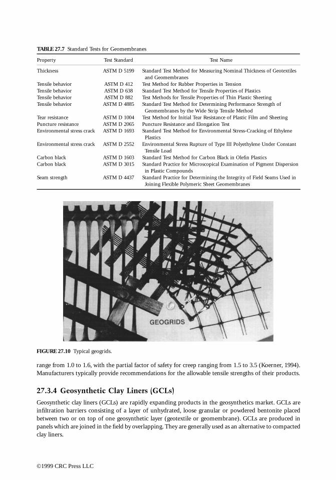
range from 1.0 to 1.6, with the partial factor of safety for creep ranging from 1.5 to 3.5 (Koerner, 1994).Manufacturers typically provide recommendations for the allowable tensile strengths of their products.
27.3.4 Geosynthetic Clay Liners (GCLs)
Geosynthetic clay liners (GCLs) are rapidly expanding products in the geosynthetics market. GCLs areinfiltration barriers consisting of a layer of unhydrated, loose granular or powdered bentonite placedbetween two or on top of one geosynthetic layer (geotextile or geomembrane). GCLs are produced inpanels which are joined in the field by overlapping. They are generally used as an alternative to compactedclay liners.
TABLE 27.7 Standard Tests for Geomembranes
Property Test Standard Test Name
Thickness ASTM D 5199 Standard Test Method for Measuring Nominal Thickness of Geotextiles and Geomembranes
Tensile behavior ASTM D 412 Test Method for Rubber Properties in TensionTensile behavior ASTM D 638 Standard Test Method for Tensile Properties of PlasticsTensile behavior ASTM D 882 Test Methods for Tensile Properties of Thin Plastic SheetingTensile behavior ASTM D 4885 Standard Test Method for Determining Performance Strength of
Geomembranes by the Wide Strip Tensile MethodTear resistance ASTM D 1004 Test Method for Initial Tear Resistance of Plastic Film and SheetingPuncture resistance ASTM D 2065 Puncture Resistance and Elongation TestEnvironmental stress crack ASTM D 1693 Standard Test Method for Environmental Stress-Cracking of Ethylene
PlasticsEnvironmental stress crack ASTM D 2552 Environmental Stress Rupture of Type III Polyethylene Under Constant
Tensile LoadCarbon black ASTM D 1603 Standard Test Method for Carbon Black in Olefin PlasticsCarbon black ASTM D 3015 Standard Practice for Microscopical Examination of Pigment Dispersion
in Plastic CompoundsSeam strength ASTM D 4437 Standard Practice for Determining the Integrity of Field Seams Used in
Joining Flexible Polymeric Sheet Geomembranes
FIGURE 27.10 Typical geogrids.
©1999 CRC Press LLC
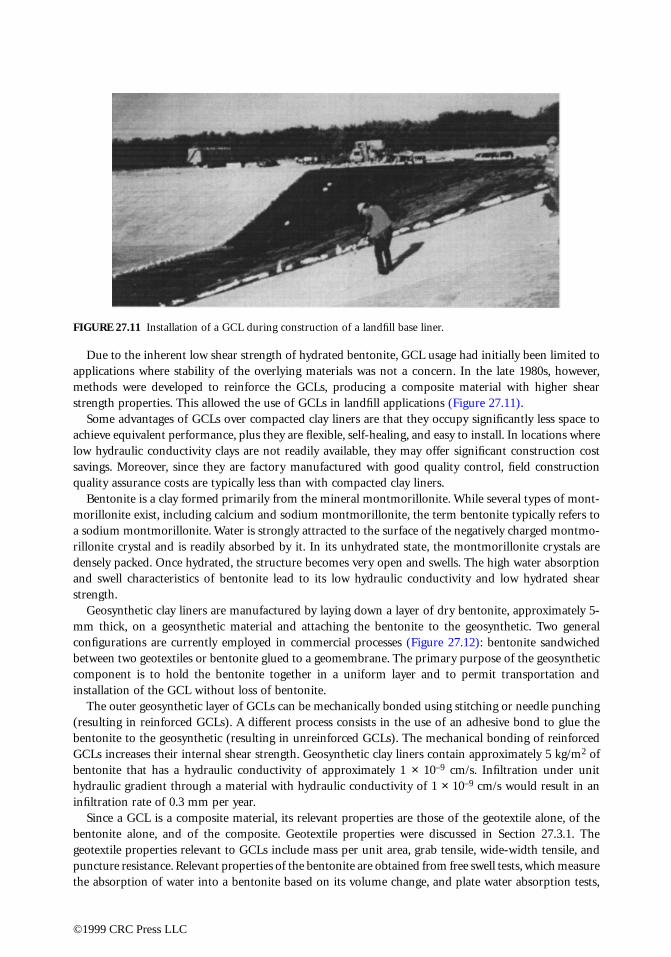
Due to the inherent low shear strength of hydrated bentonite, GCL usage had initially been limited toapplications where stability of the overlying materials was not a concern. In the late 1980s, however,methods were developed to reinforce the GCLs, producing a composite material with higher shearstrength properties. This allowed the use of GCLs in landfill applications (Figure 27.11).
Some advantages of GCLs over compacted clay liners are that they occupy significantly less space toachieve equivalent performance, plus they are flexible, self-healing, and easy to install. In locations wherelow hydraulic conductivity clays are not readily available, they may offer significant construction costsavings. Moreover, since they are factory manufactured with good quality control, field constructionquality assurance costs are typically less than with compacted clay liners.
Bentonite is a clay formed primarily from the mineral montmorillonite. While several types of mont-morillonite exist, including calcium and sodium montmorillonite, the term bentonite typically refers toa sodium montmorillonite. Water is strongly attracted to the surface of the negatively charged montmo-rillonite crystal and is readily absorbed by it. In its unhydrated state, the montmorillonite crystals aredensely packed. Once hydrated, the structure becomes very open and swells. The high water absorptionand swell characteristics of bentonite lead to its low hydraulic conductivity and low hydrated shearstrength.
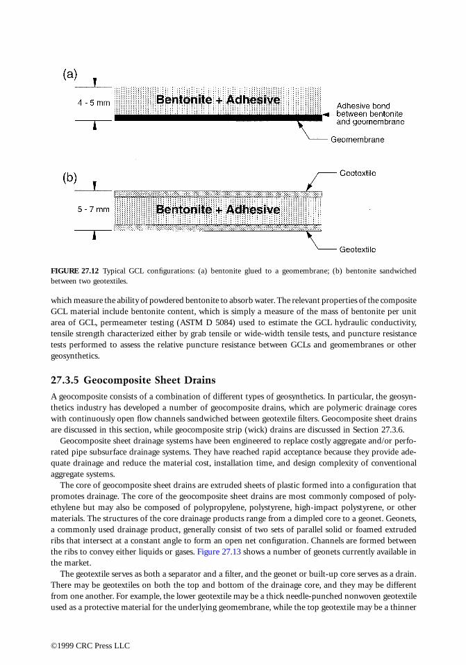
Geosynthetic clay liners are manufactured by laying down a layer of dry bentonite, approximately 5-mm thick, on a geosynthetic material and attaching the bentonite to the geosynthetic. Two generalconfigurations are currently employed in commercial processes (Figure 27.12): bentonite sandwichedbetween two geotextiles or bentonite glued to a geomembrane. The primary purpose of the geosyntheticcomponent is to hold the bentonite together in a uniform layer and to permit transportation andinstallation of the GCL without loss of bentonite.
The outer geosynthetic layer of GCLs can be mechanically bonded using stitching or needle punching(resulting in reinforced GCLs). A different process consists in the use of an adhesive bond to glue thebentonite to the geosynthetic (resulting in unreinforced GCLs). The mechanical bonding of reinforcedGCLs increases their internal shear strength. Geosynthetic clay liners contain approximately 5 kg/m2 ofbentonite that has a hydraulic conductivity of approximately 1 × 10⁻⁹ cm/s. Infiltration under unithydraulic gradient through a material with hydraulic conductivity of 1 × 10⁻⁹ cm/s would result in aninfiltration rate of 0.3 mm per year.
Since a GCL is a composite material, its relevant properties are those of the geotextile alone, of thebentonite alone, and of the composite. Geotextile properties were discussed in Section 27.3.1. Thegeotextile properties relevant to GCLs include mass per unit area, grab tensile, wide-width tensile, andpuncture resistance. Relevant properties of the bentonite are obtained from free swell tests, which measurethe absorption of water into a bentonite based on its volume change, and plate water absorption tests,
FIGURE 27.11 Installation of a GCL during construction of a landfill base liner.
©1999 CRC Press LLC
which measure the ability of powdered bentonite to absorb water. The relevant properties of the compositeGCL material include bentonite content, which is simply a measure of the mass of bentonite per unitarea of GCL, permeameter testing (ASTM D 5084) used to estimate the GCL hydraulic conductivity,tensile strength characterized either by grab tensile or wide-width tensile tests, and puncture resistancetests performed to assess the relative puncture resistance between GCLs and geomembranes or othergeosynthetics.
27.3.5 Geocomposite Sheet Drains
A geocomposite consists of a combination of different types of geosynthetics. In particular, the geosyn-thetics industry has developed a number of geocomposite drains, which are polymeric drainage coreswith continuously open flow channels sandwiched between geotextile filters. Geocomposite sheet drainsare discussed in this section, while geocomposite strip (wick) drains are discussed in Section 27.3.6.
Geocomposite sheet drainage systems have been engineered to replace costly aggregate and/or perfo-rated pipe subsurface drainage systems. They have reached rapid acceptance because they provide ade-quate drainage and reduce the material cost, installation time, and design complexity of conventionalaggregate systems.
The core of geocomposite sheet drains are extruded sheets of plastic formed into a configuration thatpromotes drainage. The core of the geocomposite sheet drains are most commonly composed of poly-ethylene but may also be composed of polypropylene, polystyrene, high-impact polystyrene, or othermaterials. The structures of the core drainage products range from a dimpled core to a geonet. Geonets,a commonly used drainage product, generally consist of two sets of parallel solid or foamed extrudedribs that intersect at a constant angle to form an open net configuration. Channels are formed betweenthe ribs to convey either liquids or gases. Figure 27.13 shows a number of geonets currently available inthe market.
The geotextile serves as both a separator and a filter, and the geonet or built-up core serves as a drain.There may be geotextiles on both the top and bottom of the drainage core, and they may be differentfrom one another. For example, the lower geotextile may be a thick needle-punched nonwoven geotextileused as a protective material for the underlying geomembrane, while the top geotextile may be a thinner
FIGURE 27.12 Typical GCL configurations: (a) bentonite glued to a geomembrane; (b) bentonite sandwichedbetween two geotextiles.
©1999 CRC Press LLC

nonwoven or woven product. Composite drainage nets are typically formed by thermally bonding thegeotextile and geonet. Glueing and solvent welding can also be used to bond the geosynthetic core to thegeotextile. In producing geocomposite drainage nets, the melt temperatures of the geotextile and geonetmust be compatible so that the properties of each material are retained. Figure 27.14 shows a numberof available geocomposite sheet drainage materials.
Since the purpose of the core is drainage, the most important properties to include in specificationsare thickness, crush strength, and transmissivity under load. Table 27.8 summarizes the tests commonlyperformed to evaluate the properties of geocomposite sheet drains. It is also important to evaluatefiltration requirements for the geotextile. Design of geocomposite drains is covered by Holtz et al. (1997).
FIGURE 27.13 Typical geonets used as the core of geocomposite sheet drains.
FIGURE 27.14 Typical geocomposite sheet drains.
©1999 CRC Press LLC

27.3.6 Geocomposite Strip (Wick) Drains
Geocomposite strip drains, also called “wick drains,” have been developed to replace the use of sanddrains in applications involving the increase in consolidation rate of soft, saturated fine-grained soils.Geocomposite strip drains actually do not wick moisture, but simply provide a conduit for pore waterpressure-induced flow. They are placed vertically through high water content silts and clays to produceshort drainage paths and thus increase the rate of consolidation. Other names commonly used for theseproducts are “band shaped drains” and “prefabricated vertical drains.”
Sand drains were originally introduced in the 1930s as a method for improvement of soft soil foun-dations. The method of rapid consolidation of saturated fine-grained soils using sand drains involvesplacement of vertical columns of sand (usually 200 to 450 mm in diameter) at spacings of 1.5 to 6.0 mcenters throughout the subsurface to be dewatered. Now, the use of geocomposite strip drains dominatesover the use of sand drains in projects involving dewatering of saturated fine-grained soils. Their lengthsare site-specific but usually extend to the bottom of the soft layer(s). Once installed, a surcharge load isplaced on the ground surface to mobilize excess pore water pressures. This surcharge load is placed inincremental lifts, which induce pore water pressures in the underlying soil. The pore water pressures arethen dissipated through the vertical drains. Water takes the shortest drainage path (i.e., horizontallyradial) to the vertical drain, at which point it flows vertically since the drain has a much higher hydraulicconductivity than the fine-grained soil being consolidated. The rate at which surcharge fill is added iscritical in this process.
Most commercially available geocomposite strip drains have adequate capacity to drain the waterexpelled during consolidation of the fine-grained soils. Since their flow capacity is usually adequate,selection of the spacing of the vertical drains is governed by the consolidation rate required in the project.Hansbo’s equation (Hansbo, 1979) is generally used to estimate the time required to achieve a desiredpercentage of consolidation as a function of the horizontal coefficient of consolidation of the foundationsoil, the equivalent diameter of the geocomposite strip drain, and the spacing of the drains. As withgeocomposite sheet drains, the geotextile covering or wrapping serves primarily a filtration function.Determining the filtration requirements for the geotextile is an essential element of the design.
Installation of geocomposite strip drains is very rapid and uses lightweight construction equipmentfitted with hollow leads (called “lances” or mandrels) for insertion to the desired depth. The bottom ofthe lance should be covered by an expendable shoe which keeps soil out of the lance so as not to bindthe strip drain within it. The allowable flow rate of geocomposite strip drains is determined by ASTMD4716 test method. Typical values of ultimate flow rate at a hydraulic gradient of 1.0 under 207 kPanormal stress vary from 1.5 to 3.0 m3/sec.-m. This value must then be reduced on the basis of site-specificpartial factors of safety. Specifications for geocomposite strip drains are covered in Holtz et al. (1997).
27.3.7 Geocells
Geocells (or cellular confinement systems) are three-dimensional, expandable panels made from HDPEor polyester strips. When expanded during installation, the interconnected strips form the walls of aflexible, three-dimensional cellular structure into which specified infill materials are placed and com-pacted (Figure 27.15). This creates a system that holds the infill material in place and prevents mass
TABLE 27.8 Standard Tests for Geocomposite Drainage Nets
Property Test Standard Test Name
Thickness ASTM D 5199 Standard Test Method for Measuring Nominal Thickness of Geotextiles and Geomembranes
Crush strength ASTM D 1621 Standard Test Method for Compressive Properties of Rigid Cellular PlasticsTransmissivity ASTM D 4716 Standard Test Method for Constant Head Hydraulic Transmissivity (In-Plane Flow)
of Geotextiles and Geotextile Related Products
©1999 CRC Press LLC
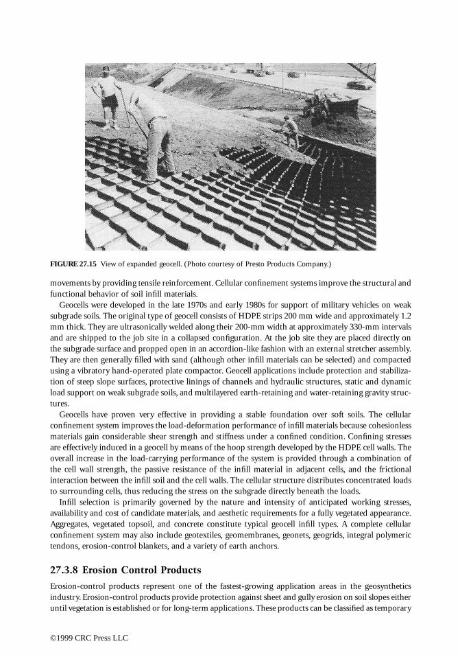
movements by providing tensile reinforcement. Cellular confinement systems improve the structural andfunctional behavior of soil infill materials.
Geocells were developed in the late 1970s and early 1980s for support of military vehicles on weaksubgrade soils. The original type of geocell consists of HDPE strips 200 mm wide and approximately 1.2mm thick. They are ultrasonically welded along their 200-mm width at approximately 330-mm intervalsand are shipped to the job site in a collapsed configuration. At the job site they are placed directly onthe subgrade surface and propped open in an accordion-like fashion with an external stretcher assembly.They are then generally filled with sand (although other infill materials can be selected) and compactedusing a vibratory hand-operated plate compactor. Geocell applications include protection and stabiliza-tion of steep slope surfaces, protective linings of channels and hydraulic structures, static and dynamicload support on weak subgrade soils, and multilayered earth-retaining and water-retaining gravity struc-tures.
Geocells have proven very effective in providing a stable foundation over soft soils. The cellularconfinement system improves the load-deformation performance of infill materials because cohesionlessmaterials gain considerable shear strength and stiffness under a confined condition. Confining stressesare effectively induced in a geocell by means of the hoop strength developed by the HDPE cell walls. Theoverall increase in the load-carrying performance of the system is provided through a combination ofthe cell wall strength, the passive resistance of the infill material in adjacent cells, and the frictionalinteraction between the infill soil and the cell walls. The cellular structure distributes concentrated loadsto surrounding cells, thus reducing the stress on the subgrade directly beneath the loads.
Infill selection is primarily governed by the nature and intensity of anticipated working stresses,availability and cost of candidate materials, and aesthetic requirements for a fully vegetated appearance.Aggregates, vegetated topsoil, and concrete constitute typical geocell infill types. A complete cellularconfinement system may also include geotextiles, geomembranes, geonets, geogrids, integral polymerictendons, erosion-control blankets, and a variety of earth anchors.
27.3.8 Erosion Control Products
Erosion-control products represent one of the fastest-growing application areas in the geosyntheticsindustry. Erosion-control products provide protection against sheet and gully erosion on soil slopes eitheruntil vegetation is established or for long-term applications. These products can be classified as temporary
FIGURE 27.15 View of expanded geocell. (Photo courtesy of Presto Products Company.)
©1999 CRC Press LLC
degradable erosion control blankets, long-term nondegradable erosion control mats, and permanent hardarmored systems.
Temporary degradable erosion control blankets are used to enhance the establishment of vegetation.These products are used where vegetation alone would provide sufficient site protection after the erosioncontrol product has degraded. Some of these products are completely biodegradable (e.g., straw, hay,jute, and hydraulic mulches), while others are only partially biodegradable (e.g., erosion control meshesand nets). Long-term nondegradable erosion control mats provide permanent reinforcement of vegeta-tion root structure. They are used in critical erosion-control applications where immediate high-perfor-mance erosion protection, followed by the permanent reinforcement of established vegetation is required.These soft armor-related products provide erosion control, aid in vegetative growth, and eventuallybecome entangled with the vegetation to provide reinforcement to the root system. Finally, the permanenthard armored systems include geocell products with concrete infill, vegetated concrete block systems,and fabric-formed revetments.
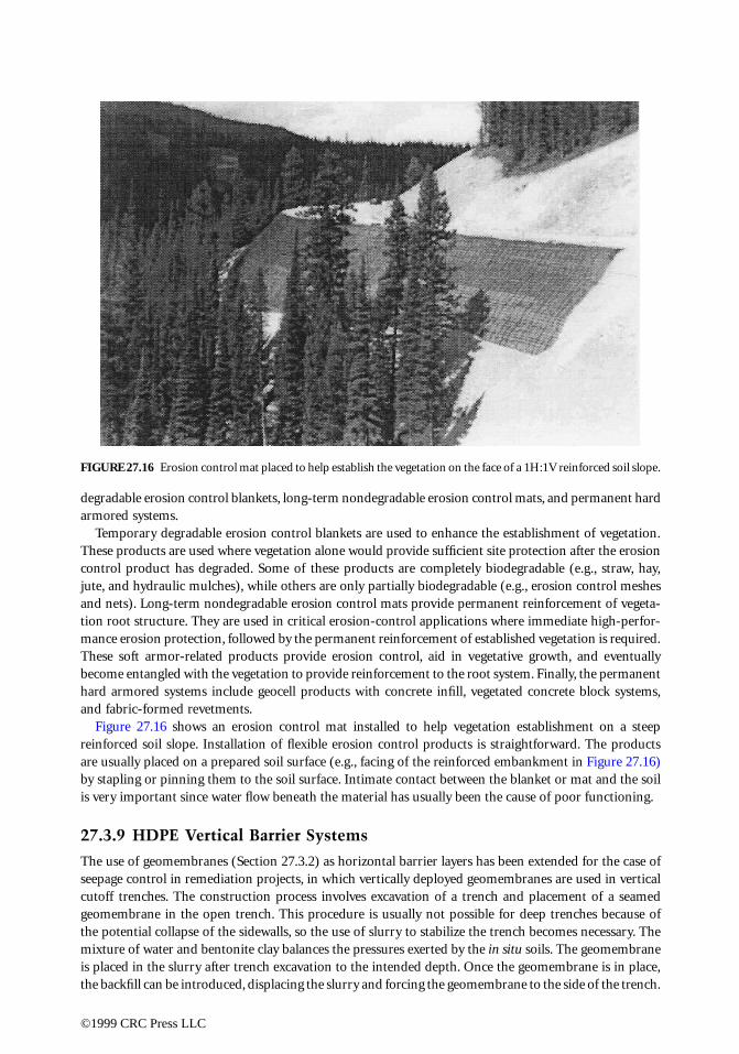
Figure 27.16 shows an erosion control mat installed to help vegetation establishment on a steepreinforced soil slope. Installation of flexible erosion control products is straightforward. The productsare usually placed on a prepared soil surface (e.g., facing of the reinforced embankment in Figure 27.16)by stapling or pinning them to the soil surface. Intimate contact between the blanket or mat and the soilis very important since water flow beneath the material has usually been the cause of poor functioning.
27.3.9 HDPE Vertical Barrier Systems
The use of geomembranes (Section 27.3.2) as horizontal barrier layers has been extended for the case ofseepage control in remediation projects, in which vertically deployed geomembranes are used in verticalcutoff trenches. The construction process involves excavation of a trench and placement of a seamedgeomembrane in the open trench. This procedure is usually not possible for deep trenches because ofthe potential collapse of the sidewalls, so the use of slurry to stabilize the trench becomes necessary. Themixture of water and bentonite clay balances the pressures exerted by the in situ soils. The geomembraneis placed in the slurry after trench excavation to the intended depth. Once the geomembrane is in place,the backfill can be introduced, displacing the slurry and forcing the geomembrane to the side of the trench.
FIGURE 27.16 Erosion control mat placed to help establish the vegetation on the face of a 1H:1V reinforced soil slope.
©1999 CRC Press LLC
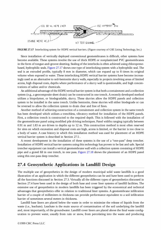
Since installation of vertically deployed conventional geomembranes is difficult, other systems havebecome available. These systems involve the use of thick HDPE or nonplasticized PVC geomembranesin the form of tongue-and-groove sheeting. Sealing of the interlocks is often achieved using chloroprene-based, hydrophilic seals. Figure 27.17 shows one type of interlocking system with a hydrophilic seal. Theseal is an extruded profile, typically 8 mm in diameter, which can expand up to 8 times its originalvolume when exposed to water. These interlocking HDPE vertical barrier systems have become increas-ingly used as an alternative to soil-bentonite slurry walls, especially in projects involving areas of limitedaccess, high disposal costs, depths where performance of a slurry wall is questionable, and high concen-trations of saline and/or chemicals.
An additional advantage of the HDPE vertical barrier system is that both a containment and a collectionsystem (e.g., a geocomposite sheet drain) can be constructed in one trench. A recently developed methodutilizes a biopolymer, or biodegradable, slurry. These slurries allow the HDPE panels and collectionsystem to be installed in the same trench. Unlike bentonite, these slurries will either biodegrade or canbe reversed to allow the collection system to drain clear and free of fines.
Another method of achieving construction of a containment and collection system in the same trenchhas been developed which utilizes a trenchless, vibratory method for installation of the HDPE panels.First, a collection trench is constructed to the required depth. This is followed with the installation ofthe geomembrane panel using modified pile driving techniques. Panel widths ranging typically between0.91 m and 1.83 m are driven to depths up to 12 m. This construction method is most often reservedfor sites on which excavation and disposal costs are high, access is limited, or the barrier is too close toa body of water. A case history in which this installation method was used for placement of an HDPEvertical barrier system is described in Section 27.5 .
A recent development in the installation of these systems is the use of a “one-pass” deep trencher.Installation of HDPE vertical barrier systems using this technology has proven to be fast and safe. Specialtrencher equipment can install a vertical geomembrane wall with a collection system consisting of HDPEpipe and a gravel fill in one trench, in one pass. Figure 27.18 shows the placement of an HDPE panelusing this one-pass deep trencher.
27.4 Geosynthetic Applications in Landfill Design
The multiple use of geosynthetics in the design of modern municipal solid waste landfills is a goodillustration of an application in which the different geosynthetics can be and have been used to performall the functions discussed in Section 27.3. Virtually all the different types of geosynthetics discussed inSection 27.4 have been used in the design of both base and cover liner systems of landfill facilities. Theextensive use of geosynthetics in modern landfills has been triggered by the economical and technicaladvantages that geosynthetics offer in relation to traditional liner systems. A geomembrane infiltrationbarrier of a couple of millimiters in thickness can provide performance equivalent to a soil infiltrationbarrier of sometimes several meters in thickness.
Landfill base liners are placed below the waste in order to minimize the release of liquids from thewaste (i.e., leachate). Leachate is the main source of contamination of the soil underlying the landfilland, most importantly, of the groundwater. Landfill cover liners are placed above the final waste config-uration to prevent water, usually from rain or snow, from percolating into the waste and producing
FIGURE 27.17 Interlocking system for HDPE vertical barriers. (Figure courtesy of GSE Lining Technology, Inc.)
©1999 CRC Press LLC
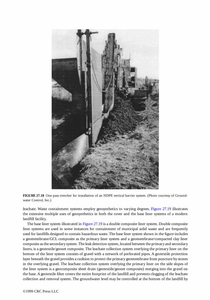
leachate. Waste containment systems employ geosynthetics to varying degrees. Figure 27.19 illustratesthe extensive multiple uses of geosynthetics in both the cover and the base liner systems of a modernlandfill facility.
The base liner system illustrated in Figure 27.19 is a double composite liner system. Double compositeliner systems are used in some instances for containment of municipal solid waste and are frequentlyused for landfills designed to contain hazardous waste. The base liner system shown in the figure includesa geomembrane/GCL composite as the primary liner system and a geomembrane/compacted clay linercomposite as the secondary system. The leak detection system, located between the primary and secondaryliners, is a geotextile/geonet composite. The leachate collection system overlying the primary liner on thebottom of the liner system consists of gravel with a network of perforated pipes. A geotextile protectionlayer beneath the gravel provides a cushion to protect the primary geomembrane from puncture by stonesin the overlying gravel. The leachate collection system overlying the primary liner on the side slopes ofthe liner system is a geocomposite sheet drain (geotextile/geonet composite) merging into the gravel onthe base. A geotextile filter covers the entire footprint of the landfill and prevents clogging of the leachatecollection and removal system. The groundwater level may be controlled at the bottom of the landfill by
FIGURE 27.18 One pass trencher for installation of an HDPE vertical barrier system. (Photo courtesy of Ground-water Control, Inc.)
©1999 CRC Press LLC
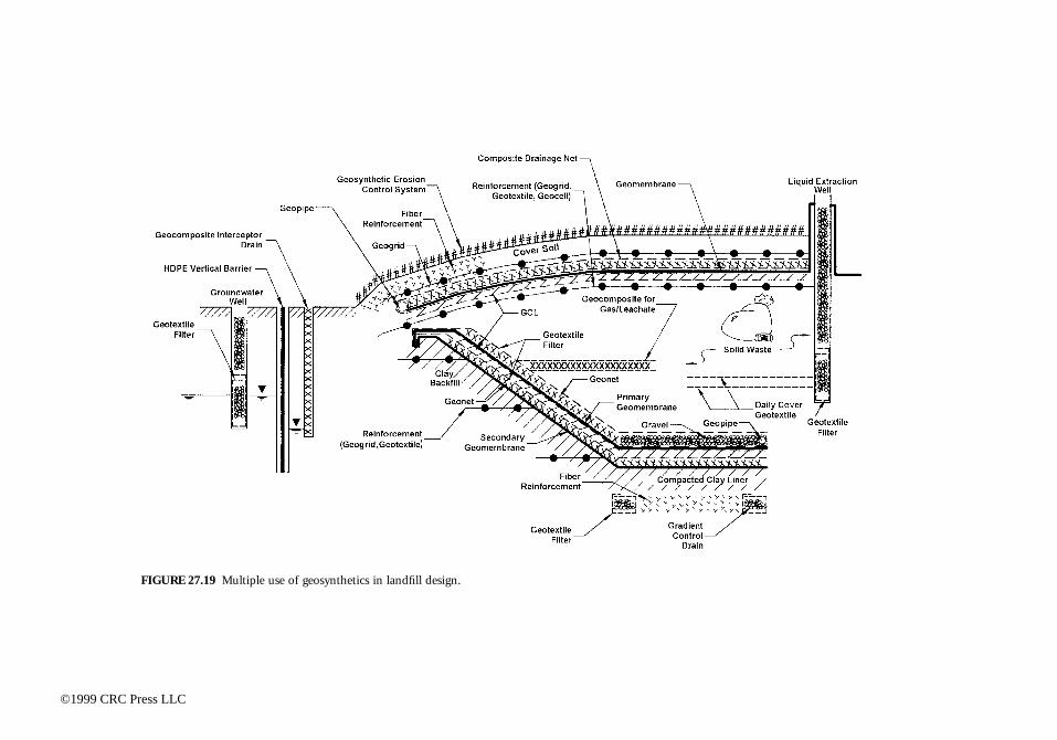
FIGURE 27.19 Multiple use of geosynthetics in landfill design.
©1999 CRC Press LLC
gradient control drains built using geotextile filters. Moreover, the foundation soil below the bottom ofthe landfill may be stabilized as shown in the figure using randomly distributed fiber reinforcements,while the steep side soil slopes beneath the liner could also be reinforced using geogrids. Different typesof geosynthetics (e.g. geogrids, geotextiles, fibers) could have been selected for stabilization of the foun-dation soils.
The cover system of the landfill illustrated in Figure 27.19 contains a composite geomembrane/GCLbarrier layer. The drainage layer overlying the geomembrane is a geocomposite sheet drain (compositegeotextile/geonet). In addition, the soil cover system may include geogrid, geotextile, or geocell reinforce-ments below the infiltration barrier system. This layer of reinforcements may be used to minimize thestrains that could be induced in the barrier layers by differential settlements of the refuse or by a futurevertical expansion of the landfill. In addition, the cover system could include a geogrid or geotextilereinforcement above the infiltration barrier to provide stability to the vegetative cover soil. Fiber rein-forcement may also be used for stabilization of the steep portion of the vegetative cover soil. A geocom-posite erosion control system above the vegetative cover soil is indicated in the figure and providesprotection against sheet and gully erosion.
Figure 27.19 also illustrates the use of geosynthetics within the waste mass, which are used to facilitatewaste placement during landfilling. Specifically, the figure illustrates the use of geotextiles as daily coverlayers and of geocomposites within the waste mass for collection of gas and leachate. Geosynthetics canalso be used as part of the groundwater and leachate collection well system. The use of geotextiles asfilters in groundwater and leachate extraction wells is illustrated in the figure. Finally, the figure showsthe use of an HDPE vertical barrier system and a geocomposite interceptor drain along the perimeter ofthe landfill facility. Although not all of the components shown in Figure 27.19 would normally be neededat any one landfill facility, the figure illustrates the many geosynthetic applications that can be consideredin landfill design.
27.5 Case History of Vertical Barrier System
Although the use of geosynthetics in many geotechnical and environmental projects is related indirectlyto groundwater applications (e.g., landfill liners, which prevent groundwater contamination), a geosyn-thetic application directly related to groundwater remediation and control is the use of HDPE panels asvertical barrier systems. A case history is presented herein to illustrate the use of HDPE panels as partof a remediation plan for a site contaminated with coal tar (Burson et al., 1997).
The site was a defunct manufactured gas plant in York, Pennsylvania. The site is surrounded bycommercial and residential areas, and a creek (Codorus Creek) borders the site for a distance of approx-imately 305 meters. During years of operation and the subsequent closing of the manufactured gas plant,some process residuals migrated to subsurface soils and groundwater. Over time, the presence of coaltar-like material in the form of dense nonaqueous phase liquid (DNAPL), was observed seeping fromthe bank of the Codorus Creek. DNAPL was also noted in some monitoring wells on site.
Several remediation scenarios were evaluated with the purpose of intercepting the tar-like materialmigrating through the soil and into groundwater, encountered approximately 5.0 m below ground surface.A system consisting of a combination of soil improvement by jet grouting, a vertical barrier using HDPEpanels, and a network of recovery wells was finally selected.
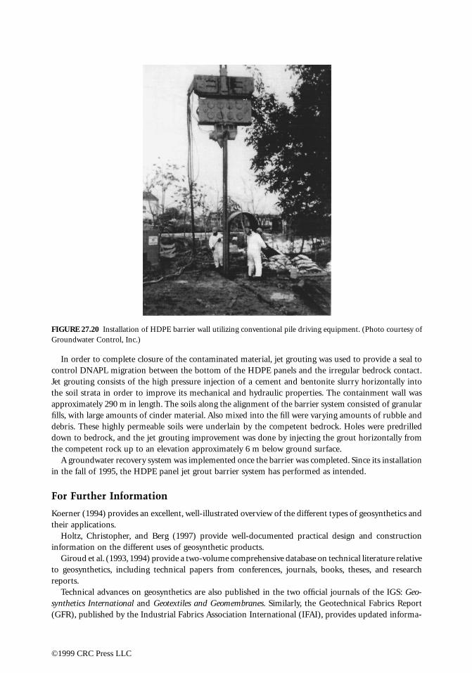
The use of vertical HDPE panels and trenchless technology allowed placement of the barrier as closeas 3 m from the bank of Codorus Creek, which was considered not to be feasible with conventional slurrywall technology. The HDPE barrier system selected for this project was a 2-mm-thick geomembrane,which allowed for the vibratory, trenchless installation. Sealing of the interlocks was achieved with achloroprene-based, hydrophilic seal (see Figure 27.17). HDPE panels were keyed into soil improved byjet grouting, as discussed below. The panels were installed using conventional vibratory pile drivingequipment, without a trench, thus reducing the amount of contaminated spoils to be disposed of (Figure27.20).
©1999 CRC Press LLC
In order to complete closure of the contaminated material, jet grouting was used to provide a seal tocontrol DNAPL migration between the bottom of the HDPE panels and the irregular bedrock contact.Jet grouting consists of the high pressure injection of a cement and bentonite slurry horizontally intothe soil strata in order to improve its mechanical and hydraulic properties. The containment wall wasapproximately 290 m in length. The soils along the alignment of the barrier system consisted of granularfills, with large amounts of cinder material. Also mixed into the fill were varying amounts of rubble anddebris. These highly permeable soils were underlain by the competent bedrock. Holes were predrilleddown to bedrock, and the jet grouting improvement was done by injecting the grout horizontally fromthe competent rock up to an elevation approximately 6 m below ground surface.
A groundwater recovery system was implemented once the barrier was completed. Since its installationin the fall of 1995, the HDPE panel jet grout barrier system has performed as intended.
For Further Information
Koerner (1994) provides an excellent, well-illustrated overview of the different types of geosynthetics andtheir applications.
Holtz, Christopher, and Berg (1997) provide well-documented practical design and constructioninformation on the different uses of geosynthetic products.
Giroud et al. (1993, 1994) provide a two-volume comprehensive database on technical literature relativeto geosynthetics, including technical papers from conferences, journals, books, theses, and researchreports.
Technical advances on geosynthetics are also published in the two official journals of the IGS: Geo-synthetics International and Geotextiles and Geomembranes. Similarly, the Geotechnical Fabrics Report(GFR), published by the Industrial Fabrics Association International (IFAI), provides updated informa-
FIGURE 27.20 Installation of HDPE barrier wall utilizing conventional pile driving equipment. (Photo courtesy ofGroundwater Control, Inc.)
©1999 CRC Press LLC
tion, including the annual Specifier’s Guide, which offers a summary of the properties of products availablein the geosynthetics market.
The ASTM Standards on Geosynthetics, sponsored by ASTM Committee D-35 on Geosynthetics (ASTM,1995), provides information on the standard test procedures for the different types of geosynthetics.
The Proceedings of the International Conferences on Geosynthetics, organized by the InternationalGeosynthetic Society (IGS), offer a relevant source of information on the different topics related togeosynthetics. These international conferences are organized every four years. Equally relevant are theproceedings of conferences organized by the regional chapters of IGS. Particularly, the proceedings ofconferences organized by the North American Geosynthetics Society (NAGS) every two years are animportant source. Finally, the proceedings of the series of conferences organized by the GeosyntheticsResearch Institute (GRI) provide information on specific topics relevant to geosynthetic design.
Geosynthetic manufacturers’ literature is also a valuable source of information, providing product-specific properties, suggested design methods, and recommended safety factors.
References
ASTM. 1995. ASTM Standards on Geosynthetics. Sponsored by ASTM Committee D-35 on Geosynthetics,Fourth Edition, 178p.
Bhatia, S. K. and Smith, J. L. 1996a. Geotextile characterization and pore-size distribution: Part I. Areview of manufacturing processes, Geosynthetics International. 3, 1, 85-105.
Bhatia, S. K. and Smith, J. L. 1996b. Geotextile characterization and pore-size distribution: Part II. Areview of test methods and results. Geosynthetics International. 3, 2, 155-180.
Bhatia, S. K., Smith, J. L., and Christopher, B. R. 1996. Geotextile characterization and pore-size distri-bution: Part III. Comparison of methods and application to design. Geosynthetics International. 3,3, 301-328.
Burson, B., Baker, A. C., Jones, B., and Shailer, J. 1997. Development and installation of an innovativevertical containment system. Proceedings of the Geosynthetics '97 Conference, Long Beach, Cali-fornia, March 1997, 1, 467-480.
Christopher, B. R. and Fischer, G.R. 1992. Geotextile filtration principles, practices and problems. Journalof Geotextiles and Geomembranes. 11, 4-6, 337-354.
Christopher, B. R. and Holtz, R. D. 1985. Geotextiles Engineering Manual, National Highway Institute,FHWA, Washington, D.C.
Christopher, B. R., Gill, S. A., Giroud, J. P., Juran, I., Mitchell, J., Schlosser, F., and Dunnicliff, J. 1989.Design and Construction Guidelines for Reinforced Soil Structures, Volume I, Report FHWA-RD-89-043. Federal Highway Administration, U.S. Department of Transportation, Washington, D.C.
Elias, V. and Christopher, B. R. 1997. Mechanically Stabilized Earth Walls and Reinforced Soil SlopesDesign and Construction Guidelines, Publication No. FHWA-SA-96-071 Federal Highway Admin-istration, U.S. Department of Transportation, Washington, D.C., 371 p.
Gerry, G. S. and Raymond, G. P. 1983. The in-plane permeability of geotextiles, Geotechnical TestingJournal, ASTM, 6, 4, December 1983, 181-189.
Giroud, J. P. (with cooperation of Beech, J.F. and Khatami, A.). 1993. Geosynthetics Bibliography. Volume1. IGS, Industrial Fabrics Association International (IFAI) Publishers, St. Paul, MN.
Giroud, J. P. (with cooperation of Beech, J.F., Khatami, A., and Badu-Tweneboah, K.). 1994. GeosyntheticsBibliography. Volume 2. IGS, Industrial Fabrics Association International (IFAI) Publishers, St. Paul,MN.
Giroud, J. P. 1996. Granular filters and geotextile filters. Proceedings of Geofilters ‘96, Montreal, 565-680.Haliburton, T. A. and Wood, P. D. 1982. Evaluation of U.S. Army Corps of Engineers gradient ratio test
for geotextile performance. Proceedings of 2nd International Conference on Geotextiles, Las Vegas,NV, 1982, IFAI, 97-101.
©1999 CRC Press LLC
Halse, Y., Koerner, R. M., and Lord, A. E., Jr. 1987. Filtration properties of geotextiles under long termtesting, Proceedings of ASCE/Penn DOT Conf. on Advances in Geotechnical Engineering, Hershey,PA. 1-13.
Hansbo, S. 1979. Consolidation of clay by band shaped perforated drains. Ground Engineering. July 1979,16-25.
Holtz, R. D., Christopher, B. R., and Berg, R. R. 1997. Geosynthetic Engineering. Bitech Publishers Ltd.,Richmond, British Columbia, Canada.
Industrial Fabrics Association International. 1996. North American Market for Geosynthetics — 1996.Koerner, R. M. 1994. Designing with Geosynthetics. Prentice Hall (3rd edition).Koerner, R. M., Wilson-Fahmy, R. F., and Narejo, D. 1996. Puncture protection of geomembranes, Part
III: Examples. Geosynthetics International, 3, 5, 655-675.Mitchell, J. K. and Villet, W. C. B. 1987. Reinforcement of earth slopes and embankments. National
Cooperative Highway Research Program, Report 290, Transportation Research Board, Washington,D.C., June.
Narejo, D., Koerner, R. M., and Wilson-Fahmy, R. F. 1996. Puncture protection of geomembranes, PartII: Experimental. Geosynthetics International. 3, 5, 629-653.
Vidal, H. 1969. La Terre Armée. Annales de l'Institut Technique du Bâtiment et des Travaux Publics, Series:Materials (38), 259-260, 1-59.
Williams, N. D. and Abouzakhm, M. A. 1989. Evaluation of geotextile/soil filtration characteristics usingthe hydraulic conductivity ratio analysis. Journal of Geotextiles and Geomembranes. 8, 1, 1-26.
Wilson-Fahmy, R. F., Narejo, D., and Koerner, R. M. 1996. Puncture protection of geomembranes, PartI: Theory. Geosynthetics International. 3, 5, 605-628.
Zornberg, J. G., Barrows, R. J., Christopher, B. R., and Wayne, M. H. 1995. Construction and instrumen-tation of a highway slope reinforced with high strength geotextiles. Proceedings of the Geosynthetics'95 Conference, Nashville, Tennessee, February 1995, 1, 13-27.
Zornberg, J. G., Sitar, N., and Mitchell, J. K. 1997. Failure Mechanisms in Geosynthetically ReinforcedSoil Slopes. Proceedings of the Fourteenth Int. Conf. on Soil Mechanics and Foundation Engineer-ing, 3, Hamburg, Germany, September 1997, 1661-1664.
Glossary
Alloys, Polymeric A blend of two or more polymers (e.g., a rubber and plastic) to improve a givenproperty (e.g., impact strength).
Apparent Opening Size (AOS), O95 For geotextile, a property which indicates the diameter of theapproximate largest particle that would effectively pass through the geotextile. At least 95% of theopenings apparently have that diameter or are smaller as measured by the dry sieve test.
Chemical Stability Stability of a geosynthetic; ability to resist degradation from chemicals, such asacids, bases, solvents, oils, and oxidation agents, and chemical reactions, including those catalyzedby light.
Chlorosulfonated Polyethylene (CSPE) Family of polymers that is produced by polyethylene reactingwith chlorine and sulfur dioxide. Present CSPEs contain 25 to 43% chlorine and 1.0 to 1.4% sulfur.
Clogging Movement by mechanical action or hydraulic flow of soil particles into the voids of fabricand retention therein, thereby reducing the hydraulic conductivity of the geotextile.
Cross-Machine Direction The axis within the plane of a fabric perpendicular to the predominant axisof the direction of production.
Cross-Plane The direction of a geosynthetic which is perpendicular to the plane of its manufactureddirection. Referred to in hydraulic situations.
Fiber Basic element of fabrics and other textile structures, characterized by having a length at least 100times its diameter or width which can be spun into a yarn or otherwise made into a fabric.
Filament Yarn The yarn made from continuous filament fibers.
©1999 CRC Press LLC
Filtration In geotextiles, the process of retaining soil in place while allowing water to pass from soil.Removal of particle from a fluid stream.
Geocell A three-dimensional structure filled with soil, thereby forming a mattress for increased stabilitywhen used with loose or compressible subsoils.
Geocomposite A manufactured material using geotextiles, geogrids, and/or geomembranes in lami-nated or composite form. May or may not include natural materials.
Geogrid Open grid structure of orthogonal filaments and strands of polymeric material used primarilyfor tensile reinforcement.
Geomembrane Very low hydraulic conductivity synthetic membrane liners or barriers used with anygeotechnical engineering-related material to control fluid migration in a man-made project, struc-ture, or system.
Geonet A geosynthetic consisting of integrally connected parallel sets of ribs overlying similar sets atvarious angles for planar drainage of liquids or gases.
Geopipe Any plastic pipe used with foundation, soil, rock, earth, or any other subsurface material asan integral part of a man-made project, structure, or system.
Geosynthetic A planar product manufactured from polymeric material used with soil, rock, earth, orother geotechnical engineering-related material as an integral part of a man-made project, struc-ture, or system.
Geosynthetic Clay Liner (GCL) Factory-manufactured hydraulic barriers consisting of a layer of ben-tonite clay or other very low permeability material supported by geotextiles and/or geomembranes,and mechanically held together by needling, stitching, or chemical adhesives.
Geotextile Any permeable textile used with foundation, soil, rock, earth, or any other geotechnicalengineering-related material as an integral part of a man-made project, structure, or system.
Grab Test In fabric testing, a tension test in which only a part of the width of the specimen is grippedin the clamps.
Gradient Ratio The ratio of the average hydraulic gradient across the fabric and the 25 mm of soilimmediately next to the fabric to the average hydraulic gradient across the 50 mm of soil between25 and 75 mm above the fabric, as measured in a constant head permeability test.
Heat Bonded Thermally bonded by melting the fibers to form weld points.Hot Wedge Common method of heat seaming of thermoplastic geomembranes by a fusing process
wherein heat is delivered by a hot wedge passing between the opposing surfaces to be bonded.Hydraulic Transmissivity For a geotextile or related product, the volumetric flow rate of water per
unit width of specimen per unit gradient in a direction parallel to the plane of the specimen.Index Test A test procedure which may contain a known bias but which may be used to establish an
order for a set of specimens with respect to the property of interest.In-Plane The direction of a geosynthetic that is parallel to its longitudinal, manufactured, or machine
direction. Referred to in hydraulic situations.Leachate Liquid that has percolated through or drained from solid waste or other human-emplaced
materials and contains soluble, partially soluble, or miscible components removed from such waste.Liner A layer of emplaced materials beneath a surface impoundment or landfill which serves to restrict
the escape of waste or its constituents from the impoundment or landfill.Machine Direction The direction in the plane of the fabric parallel to the direction of manufacture.Mass Per Unit Area The proper term to represent and compare to amount of material per unit area
(units are oz/yd2 or g/m2) of a geosynthetic.Monofilament A single filament of a fiber (normally synthetic).Mullen Burst Hydraulic bursting strength of textiles.Multifilament A yarn consisting of many continuous filaments or strands.Needlepunched In geotextiles, mechanical bonding of staple or filament fibers with barbed needles to
form a compact fabric.Nonwoven Fabric A textile structure produced by bonding or interlocking fibers, or both, accomplished
by mechanical, thermal, or chemical means.
©1999 CRC Press LLC

Permittivity Of geotextiles and related products, the volumetric flow rate of water per unit cross-sectionalarea per unit head under laminar flow conditions, in the normal direction through a geotextile.
Plasticizer A plasticizer is a material, frequently solvent-like, incorporated into a plastic or a rubber toincrease its ease of workability, its flexibility, or distensibility.
Polyester Fiber Generic name for a manufactured fiber in which the fiber-forming substance is anylong-chain synthetic polymer composed of an ester of a dihydric alcohol and terephthalic acid.
Polyethylene A polyolefin formed by bulk polymerization (for low-density) or solution polymerization(for high-density) where the ethylene monomer is placed in a reactor under high pressure andtemperature.
Polymer A macromolecular material formed by the chemical combination of monomers having eitherthe same or different chemical composition. Plastics, rubbers, and textile fibers are all high-molecular-weight polymers.
Polyolefin A family of polymeric materials that includes polypropylene and polyethylene, the formerbeing very common in geotextiles, the latter in geomembranes.
Polyvinyl Chloride (PVC) A synthetic thermoplastic polymer prepared from vinyl chloride.Quality Assurance (QA) A planned system of activities whose purpose is to provide a continuing
evaluation of the quality control program, initiating corrective action where necessary. It is appli-cable to both the manufactured product and its field installation.
Quality Control (QC) Actions that provide a means of controlling and measuring the characteristicsof (both) the manufactured and the field-installed product.
Separation The function of geosynthetics as a partition between two adjacent materials (usually dis-similar) to prevent mixing of the two materials.
Specification A precise statement of a set of requirements to be satisfied by a material, product, systemor service that indicates the procedures for determining whether each of the requirements issatisfied.
Spun-Bonded Fabrics Fabric formed by continuous filaments which have been spun (extruded),drawn, laid into a web and bonded (chemical, mechanical, or thermal bonding) together in onecontinuous process.
Staple Fibers Fiber of short lengths frequently used to make needle-punched nonwoven fabrics.Subgrade Intrusion Localized aggregate penetration of a soft cohesive subgrade and resulting displace-
ment of the subgrade into the cohesionless material.Subgrade Pumping The displacement of cohesive or low-cohesion fines from a saturated subgrade into
overlying aggregate as the result of hydraulic forces created by transmittal of wheel-load stressesto the subgrade.
Survivability The ability of a geosynthetic to be placed and to perform its intended function withoutundergoing degradation.
Tensile Strength The maximum resistance to deformation developed for a specific material whensubjected to tension by an external force.
Trapezoid Tear Test Test method used to measure the tearing strength of geotextiles.Transmissivity For a geosynthetic, the volumetric flow rate per unit thickness under laminar flow
conditions, in the in-plane direction of the fabric or geocomposite.Ultraviolet Degradation The breakdown of polymeric structure when exposed to natural light.Woven Geotextile A planar geotextile structure produced by interlacing two or more sets of elements
such as yarns, fibers, rovings of filaments where the elements pass each other usually at right anglesand one set of elements is parallel to the fabric axis.
Wide-Width Strip Tensile Test A uniaxial tensile test in which the entire width of a 200-mm-widespecimen is gripped in the clamps and the gauge length is 100 mm.
Yarn A generic term for continuous-strand strands (1 or more) of textile filaments, monofilaments, orslit form suitable for knitting, weaving, or otherwise intertwining or bonding to form a textilefabric.
Sources for these and other definitions of terms can be found in ASTM (1997) and Koerner (1994).
©1999 CRC Press LLC