Embed Size (px)
Citation preview
Recommended Descriptions of Geosynthetics Functions, Geosynthetics Terminology, Mathematical and Graphical Symbols
Foreword This is the fourth edition of the IGS mathematical and graphical symbols document. Since publication of the third edition in February 1996 a number of evolutionary changes (rather than revolutionary changes) have been made to reflect the further development and refinement of geosynthetics terminology. This edition will also be placed on the IGS Web Site to provide IGS members with ready access to current geosynthetics descriptions, terminology and mathematical and graphical symbols. IGS Secretariat 226 Sitton Road Easley South Carolina 29642 U.S.A. Tel: +1-864-855 0504 Fax: +1-864-859 1698 E-mail: [email protected]
August 2000

2 of 17
Contents Page 1. Geosynthetics Functions ..........................................................................................................3 2. Geosynthetics Terminology ......................................................................................................4 3. Mathematical Symbols...............................................................................................................7
3.1 General symbols ...................................................................................................................7 3.1.1 Dimensions 7 3.1.2 Units 7 3.1.3 Prefixes for units 7 3.1.4 Recommended subscripts 8 3.1.5 Geometry and kinetics 9
3.2 Properties related to geosynthetics.......................................................................................9
3.2.1 Physical properties 9 3.2.2 Hydraulic properties 9 3.2.3 Mechanical properties 10 3.2.4 Interface properties 11
3.3 Properties related to fluids...................................................................................................11
3.3.1 Physical properties 11 3.3.2 Flow properties 12
3.4 Properties related to geotechnics........................................................................................12
3.4.1 Physical properties 12 3.4.1.1 Solid particles and their distribution 12 3.4.1.2 Density of soils 12 3.4.1.3 Voids and water in soils 12 3.4.1.4 Consistency of soils 13
3.4.2 Stresses in soils 13 3.4.3 Hydraulic properties 13 3.4.4 Mechanical properties 13
3.4.4.1 Soil behaviour under compressive strains 13 3.4.4.2 Soil behaviour under shear strains 14
3.5 Properties related to geotechnical structures......................................................................15
3.5.1 Structure dimensions 15 3.5.2 External applied loads 15 3.5.3 Earth pressures 15
3.6 Factors of safety, partial factors and reduction factors 15
4. Graphical Symbols ...................................................................................................................16
4.1 Products ..............................................................................................................................16 4.2 Functions.............................................................................................................................16 4.3 Multiple products on same diagram ....................................................................................17
3 of 17
1. Geosynthetics Functions
Barrier: The use of a geosynthetic material to prevent the migration of liquids or gases.
Containment: The use of a geosynthetic material to contain soil or sediments to a specific geometry and prevent its loss. The contained fill takes the shape of the inflated at-rest geometry of the geosynthetic container.
Drainage (a.k.a. transmission): The use of a geosynthetic material to collect and transport fluids.
Filtration: The use of a geosynthetic material to allow passage of fluids from a soil while preventing the uncontrolled passage of soil particles.
Protection: The use of a geosynthetic material as a localised stress reduction layer to prevent or reduce damage to a given surface or layer.
Reinforcement: The use of the tensile properties of a geosynthetic material to resist stresses or contain deformations in geotechnical structures.
Separation: The use of a geosynthetic material between two dissimilar geotechnical materials to prevent intermixing.
Surficial erosion control: The use of a geosynthetic material to prevent the surface erosion of soil particles due to surface water run-off and/or wind forces.
4 of 17
2. Geosynthetics Terminology
Bituminous geomembrane: see Geomembrane, bituminous.
Bonded geogrid: see Geogrid, bonded.
Drainage composite: see Geocomposite drain.
Elastomeric geomembrane: see Geomembrane, elastomeric.
Electrokinetic geosynthetic: A composite material which may provide filtration, drainage, reinforcement in addition to electrical conduction.
Extruded geogrid: see Geogrid, extruded.
Geoarmour: A permeable geosynthetic material placed over the surface of the soil, in conjunction with pattern-placed block armour units, to prevent erosion.
Geobar: A polymeric material in the form of a bar, used in contact with soil/rock and/or any other geotechnical material in civil engineering applications.
Geoblanket: A permeable, biodegradable (synthetic or natural) structure placed over the soil for temporary erosion control applications, usually while vegetation is being established.
Geocell: A three-dimensional, permeable, polymeric (synthetic or natural) honeycomb or web structure, made of strips of geotextiles, geogrids or geomembranes linked alternatingly and used in contact with soil/rock and/or any other geotechnical material in civil engineering applications.
Geocomposite: A manufactured or assembled material using at least one geosynthetic product among the components, used in contact with soil/rock and/or any other geotechnical material in civil engineering applications.
Geocomposite clay liner: An assembled structure of geosynthetic materials and low hydraulic conductivity earth materials (clay or bentonite), in the form of a manufactured sheet, used in contact with soil/rock and/or any other geotechnical material in civil engineering applications.
Geocomposite drain: A prefabricated subsurface drainage product which consists of a geotextile filter skin supported by a geonet or a geospacer.
Geocomposite reinforcement: An assembled structure of dissimilar geosynthetic materials used for soil reinforcement.
Geofoam: A polymeric material which has been formed by the application of the polymer in semi-liquid form, through the use of a foaming agent, and results in a lightweight material with high void content, used in contact with soil/rock and/or any other geotechnical material in civil engineering applications.
Geoform: A three-dimensional, permeable geosynthetic structure, filled with soil or sediment waste such that the fill takes the shape of the inflated geoform.
Geogrid: A planar, polymeric structure consisting of a regular open network of integrally connected tensile elements, which may be linked by extrusion, bonding or interlacing, whose openings are larger than the constituents, used in contact with soil/rock and/or any other geotechnical material in civil engineering applications.
5 of 17
Geogrid, bonded: A geogrid manufactured by bonding, usually at right angles, two or more sets of strands or elements.
Geogrid, extruded: A geogrid manufactured by extruding polymers and drawing in a sheet form.
Geogrid, knitted: A geogrid manufactured by knitting together yarns or elements, usually at right angles to each other.
Geogrid, woven: A geogrid manufactured by weaving yarns or elements, usually at right angles to each other.
Geomat: A three-dimensional, permeable, polymeric structure, made of bonded filaments, used to reinforce roots of grass and small plants and extend the erosion-control limits of vegetation for permanent erosion control applications.
Geomattress: A three-dimensional, permeable geosynthetic structure, placed over the surface of a soil, and then filled with concrete mortar or soil, to prevent erosion.
Geomembrane: A planar, relatively impermeable, polymeric (synthetic or natural) sheet used in contact with soil/rock and/or any other geotechnical material in civil engineering applications.
Geomembrane, bituminous: A planar, relatively impermeable sheet manufactured from natural bituminous materials.
Geomembrane, elastomeric: A planar, relatively impermeable sheet manufactured from elastomeric polymers.
Geomembrane, plastomeric: A planar, relatively impermeable sheet manufactured from plastomeric polymers.
Geonet: A planar, polymeric structure consisting of a regular dense network, whose constituent elements are linked by knots or extrusions and whose openings are much larger than the constituents, used in contact with soil/rock and/or any other geotechnical material in civil engineering applications.
Geospacer: A three-dimensional polymeric structure with large void spaces, used in contact with soil/rock and/or any other geotechnical material in civil engineering applications.
Geostrip: A polymeric material in the form of a strip, used in contact with soil/rock and/or any other geotechnical material in civil engineering applications.
Geosynthetic: A planar, polymeric (synthetic or natural) material used in contact with soil/rock and/or any other geotechnical material in civil engineering applications.
Geotextile: A planar, permeable, polymeric (synthetic or natural) textile material, which may be nonwoven, knitted or woven, used in contact with soil/rock and/or any other geotechnical material in civil engineering applications.
Geotextile, knitted: A geotextile produced by interlooping one or more yarns, fibres, filaments or other elements.
Geotextile, nonwoven: A geotextile in the form of a manufactured sheet, web or batt of directionally or randomly orientated fibres, filaments or other elements, mechanically and/or thermally and/or chemically bonded.

6 of 17
Geotextile, woven: A geotextile produced by interlacing, usually at right angles, two or more sets of yarns, fibres, filaments, tapes or other elements.
Knitted geogrid: see Geogrid, knitted.
Knitted geotextile: see Geotextile, knitted.
Nonwoven geotextile: see Geotextile, nonwoven.
Plastomeric geomembrane: see Geomembrane, plastomeric.
Woven geogrid: see Geogrid, woven.
Woven geotextile: see Geotextile, woven.
7 of 17
3. Mathematical Symbols
3.1 General symbols
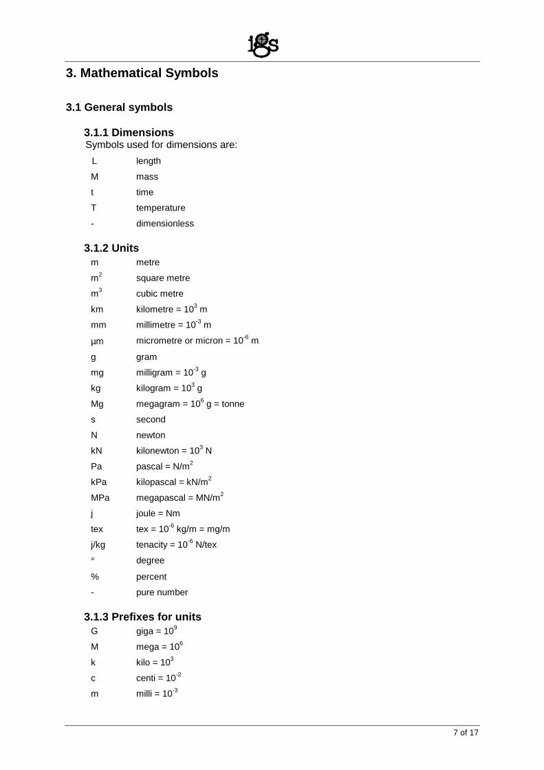
3.1.1 Dimensions Symbols used for dimensions are:
L length
M mass
t time
T temperature
- dimensionless 3.1.2 Units
m metre
m2 square metre
m3 cubic metre
km kilometre = 103 m
mm millimetre = 10-3 m
µm micrometre or micron = 10-6 m
g gram
mg milligram = 10-3 g
kg kilogram = 103 g
Mg megagram = 106 g = tonne
s second
N newton
kN kilonewton = 103 N
Pa pascal = N/m2
kPa kilopascal = kN/m2
MPa megapascal = MN/m2
j joule = Nm
tex tex = 10-6 kg/m = mg/m
j/kg tenacity = 10-6 N/tex
° degree
% percent
- pure number 3.1.3 Prefixes for units
G giga = 109
M mega = 106
k kilo = 103
c centi = 10-2
m milli = 10-3

8 of 17
µ micro = 10-6
n nano = 10-9 3.1.4 Recommended subscripts
a air, active (earth pressure), allowed
B base
cr creep reduction
cv constant volume or critical state
d dry state, diameter, design
f failure, fibre, filament, final
GSY geosynthetic material, e.g. tGSY is thickness of geosynthetic material
GBA geobar
GBL geoblanket
GCE geocell
GCD geocomposite drain
GCL geocomposite clay liner
GEC geosynthetic erosion control material
GEK electrokinetic geosynthetic
GFO geofoam
GFR geoform
GGR geogrid
GMA geomat
GMB geomembrane
GMT geomattress
GNT geonet
GSP geospacer
GST geostrip
GTX geotextile
GTXw woven geotextile
GTXnw nonwoven geotextile
h horizontal
i immediate, initial
j joint
k characteristic, e.g. Tmax,k is characteristic maximum tensile strength
m material
max maximum
min minimum
mr material reduction
n normal, number
p passive (earth pressure), planar, pullout
r radial, resistance

9 of 17
req required
s solid particles, sliding
sat saturated
sec secant
u undrained conditions
v vertical
w water x, y two orthogonal horizontal axes
z vertical axis
ε at specific strain or elongation
0 at rest (earth pressure), zero
1,2,3 principal directions 3.1.5 Geometry and kinetics
A L2 (m2) area b, B L (m) breadth or width
d L (m) diameter D L (m) depth
g Lt-2 (m/s2) acceleration due to gravity g = 9.8 m/s2 H L (m) height
l, L L (m) length t t (s) time
v Lt-1 (m/s) velocity V L3 (m3) volume
3.2 Properties related to geosynthetics 3.2.1 Physical properties
tGTX L (mm) thickness of GTX, etc.
bGTX L (m) width of GTX, etc.
ρf ML-3 (Mg/m3) density of fibres or filaments (mass per unit volume)
µA ML-2 (g/m2) mass per unit area
df L (µm) diameter of fibres or filaments
λ ML (tex) linear density of yarns, fibres, filaments
A - (%) percent open area for wovens or geogrids
nGTX - porosity (ratio between volume of voids and total volume) of a GTX
3.2.2 Hydraulic properties
On L (mm, µm) n percent opening size of a GTX - generic term
On,d L (mm, µm) n percent opening size as measured by a dry sieving test, O O S ti f d t AOS EOS
10 of 17
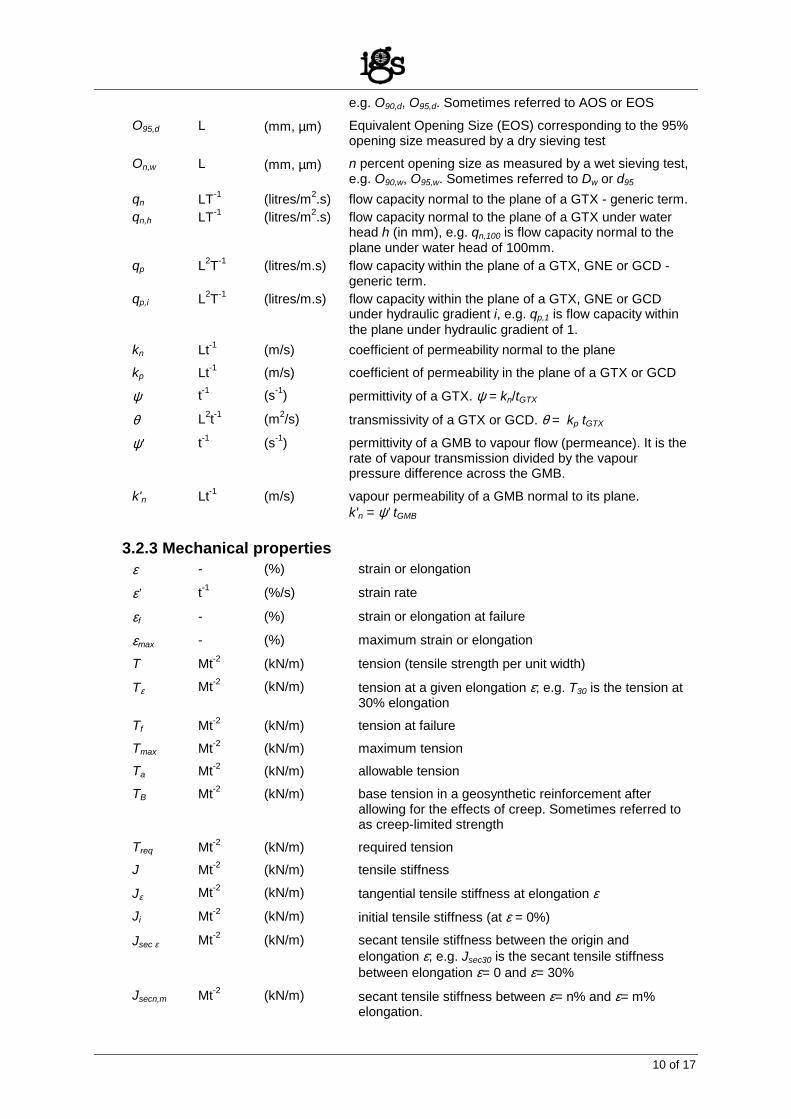
e.g. O90,d, O95,d. Sometimes referred to AOS or EOS
O95,d L (mm, µm) Equivalent Opening Size (EOS) corresponding to the 95% opening size measured by a dry sieving test
On,w L (mm, µm) n percent opening size as measured by a wet sieving test, e.g. O90,w, O95,w. Sometimes referred to Dw or d95
qn LT-1 (litres/m2.s) flow capacity normal to the plane of a GTX - generic term. qn,h LT-1 (litres/m2.s) flow capacity normal to the plane of a GTX under water
head h (in mm), e.g. qn,100 is flow capacity normal to the plane under water head of 100mm.
qp L2T-1 (litres/m.s) flow capacity within the plane of a GTX, GNE or GCD - generic term.
qp,i L2T-1 (litres/m.s) flow capacity within the plane of a GTX, GNE or GCD under hydraulic gradient i, e.g. qp,1 is flow capacity within the plane under hydraulic gradient of 1.
kn Lt-1 (m/s) coefficient of permeability normal to the plane
kp Lt-1 (m/s) coefficient of permeability in the plane of a GTX or GCD
ψ t-1 (s-1) permittivity of a GTX. ψ = kn/tGTX
θ L2t-1 (m2/s) transmissivity of a GTX or GCD. θ = kp tGTX
ψ' t-1 (s-1) permittivity of a GMB to vapour flow (permeance). It is the rate of vapour transmission divided by the vapour pressure difference across the GMB.
k'n Lt-1 (m/s) vapour permeability of a GMB normal to its plane. k'n = ψ’ tGMB
3.2.3 Mechanical properties
ε - (%) strain or elongation
ε’ t-1 (%/s) strain rate
εf - (%) strain or elongation at failure
εmax - (%) maximum strain or elongation
T Mt-2 (kN/m) tension (tensile strength per unit width)
Tε Mt-2 (kN/m) tension at a given elongation ε; e.g. T30 is the tension at 30% elongation
Tf Mt-2 (kN/m) tension at failure
Tmax Mt-2 (kN/m) maximum tension Ta Mt-2 (kN/m) allowable tension
TB Mt-2 (kN/m) base tension in a geosynthetic reinforcement after allowing for the effects of creep. Sometimes referred to as creep-limited strength
Treq Mt-2 (kN/m) required tension J Mt-2 (kN/m) tensile stiffness
Jε Mt-2 (kN/m) tangential tensile stiffness at elongation ε Ji Mt-2 (kN/m) initial tensile stiffness (at ε = 0%)
Jsec ε Mt-2 (kN/m) secant tensile stiffness between the origin and elongation ε; e.g. Jsec30 is the secant tensile stiffness between elongation ε= 0 and ε= 30%
Jsecn,m Mt-2 (kN/m) secant tensile stiffness between ε= n% and ε= m% elongation.
11 of 17
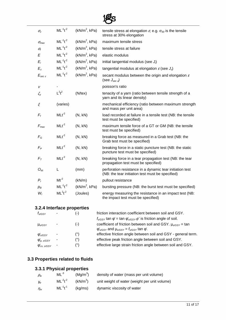
σε ML-1t-2 (kN/m2, kPa) tensile stress at elongation ε; e.g. σ30 is the tensile stress at 30% elongation
σmax ML-1t-2 (kN/m2, kPa) maximum tensile stress
σf ML-1t-2 (kN/m2, kPa) tensile stress at failure
E ML-1t-2 (kN/m2, kPa) elastic modulus
Ei ML-1t-2 (kN/m2, kPa) initial tangential modulus (see Ji)
Eε ML-1t-2 (kN/m2, kPa) tangential modulus at elongation ε (see Jε)
Esec ε ML-1t-2 (kN/m2, kPa) secant modulus between the origin and elongation ε (see Jsec ε)
ν - poisson's ratio
ζy L2t2 (N/tex) tenacity of a yarn (ratio between tensile strength of a yarn and its linear density)
ξ (varies) mechanical efficiency (ratio between maximum strength and mass per unit area)
Ff MLt-2 (N, kN) load recorded at failure in a tensile test (NB: the tensile test must be specified)
Fmax MLt-2 (N, kN) maximum tensile force of a GT or GM (NB: the tensile test must be specified)
FG MLt-2 (N, kN) breaking force as measured in a Grab test (NB: the Grab test must be specified)
FP MLt-2 (N, kN) breaking force in a static puncture test (NB: the static puncture test must be specified)
FT MLt-2 (N, kN) breaking force in a tear propagation test (NB: the tear propagation test must be specified)
Odc L (mm) perforation resistance in a dynamic tear initiation test (NB: the tear initiation test must be specified)
Pr Mt-2 (kN/m) pullout resistance pB ML-1t-2 (kN/m2, kPa) bursting pressure (NB: the burst test must be specified)
WI ML2t-2 (Joules) energy measuring the resistance in an impact test (NB: the impact test must be specified)
3.2.4 Interface properties
fs/GSY - (-) friction interaction coefficient between soil and GSY. fs/GSY tan φ‘ = tan φ‘s/GSY.φ’ is friction angle of soil.
µs/GSY - (-) coefficient of friction between soil and GSY. µs/GSY = tan φ‘s/GSY and µs/GSY = fs/GSY tan φ‘.
φ‘s/GSY - (°) effective friction angle between soil and GSY - general term. φ‘p, s/GSY - (°) effective peak friction angle between soil and GSY. φ‘cv, s/GSY - (°) effective large strain friction angle between soil and GSY.
3.3 Properties related to fluids 3.3.1 Physical properties
ρw ML-3 (Mg/m3) density of water (mass per unit volume)
γw ML-2t-2 (kN/m3) unit weight of water (weight per unit volume)
ηw ML-1t-1 (kg/ms) dynamic viscosity of water
12 of 17
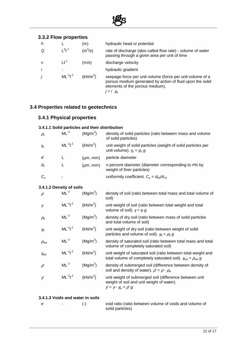
3.3.2 Flow properties
h L (m) hydraulic head or potential Q L3t-1 (m3/s) rate of discharge (also called flow rate) - volume of water
passing through a given area per unit of time
v Lt-1 (m/s) discharge velocity i - hydraulic gradient
j ML-2t-2 (kN/m3) seepage force per unit volume (force per unit volume of a porous medium generated by action of fluid upon the solid elements of the porous medium). j = i γw
3.4 Properties related to geotechnics 3.4.1 Physical properties 3.4.1.1 Solid particles and their distribution
ρs ML-3 (Mg/m3) density of solid particles (ratio between mass and volume of solid particles)
γs ML-2t-2 (kN/m3) unit weight of solid particles (weight of solid particles per unit volume). γs = ρs g
d L (µm, mm) particle diameter
dn L (µm, mm) n percent diameter (diameter corresponding to n% by weight of finer particles)
Cu - uniformity coefficient. Cu = d60/d10 3.4.1.2 Density of soils
ρ ML-3 (Mg/m3) density of soil (ratio between total mass and total volume of soil)
γ ML-2t-2 (kN/m3) unit weight of soil (ratio between total weight and total volume of soil). γ = ρ g
ρd ML-3 (Mg/m3) density of dry soil (ratio between mass of solid particles and total volume of soil)
γd ML-2t-2 (kN/m3) unit weight of dry soil (ratio between weight of solid particles and volume of soil). γd = ρd g
ρsat ML-3 (Mg/m3) density of saturated soil (ratio between total mass and total volume of completely saturated soil)
γsat ML-2t-2 (kN/m3) unit weight of saturated soil (ratio between total weight and total volume of completely saturated soil). γsat = ρsat g
ρ' ML-3 (Mg/m3) density of submerged soil (difference between density of soil and density of water). ρ' = ρ - ρw
γ' ML-2t-2 (kN/m3) unit weight of submerged soil (difference between unit weight of soil and unit weight of water). γ' = γ - γw = ρ' g
3.4.1.3 Voids and water in soils
e - (-) void ratio (ratio between volume of voids and volume of solid particles)
13 of 17
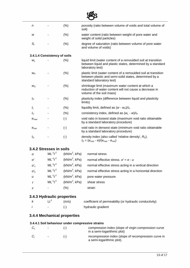
n - (%) porosity (ratio between volume of voids and total volume of soil)
w - (%) water content (ratio between weight of pore water and weight of solid particles)
Sr - (%) degree of saturation (ratio between volume of pore water and volume of voids)
3.4.1.4 Consistency of soils
wL - (%) liquid limit (water content of a remoulded soil at transition between liquid and plastic states, determined by a standard laboratory test)
wP - (%) plastic limit (water content of a remoulded soil at transition between plastic and semi-solid states, determined by a standard laboratory test)
wS - (%) shrinkage limit (maximum water content at which a reduction of water content will not cause a decrease in volume of the soil mass)
IP - (%) plasticity index (difference between liquid and plasticity limits)
IL - (%) liquidity limit, defined as (w - wP)/IP
IC - (%) consistency index, defined as (wL - w)/IP
emax - (-) void ratio in loosest state (maximum void ratio obtainable by a standard laboratory procedure)
emin - (-) void ratio in densest state (minimum void ratio obtainable by a standard laboratory procedure)
ID - (-) density index (also called 'relative density', RD). ID = (emax - e)/(emax - emin)
3.4.2 Stresses in soils
σ ML-1t-2 (kN/m2, kPa) normal stress
σ' ML-1t-2 (kN/m2, kPa) normal effective stress. σ' = σ - u
σ'v ML-1t-2 (kN/m2, kPa) normal effective stress acting in a vertical direction
σ'h ML-1t-2 (kN/m2, kPa) normal effective stress acting in a horizontal direction
u ML-1t-2 (kN/m2, kPa) pore water pressure
τ ML-1t-2 (kN/m2, kPa) shear stress
ε - (%) strain 3.4.3 Hydraulic properties
k Lt-1 (m/s) coefficient of permeability (or hydraulic conductivity) i - (-) hydraulic gradient
3.4.4 Mechanical properties 3.4.4.1 Soil behaviour under compressive strains
Cc - (-) compression index (slope of virgin compression curve in a semi-logarithmic plot)
Cr - (-) recompression index (slope of recompression curve in a semi-logarithmic plot).
14 of 17
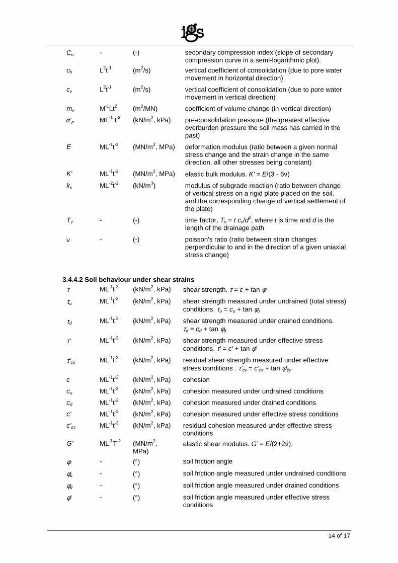
Cα - (-) secondary compression index (slope of secondary compression curve in a semi-logarithmic plot).
ch L2t-1 (m2/s) vertical coefficient of consolidation (due to pore water movement in horizontal direction)
cv L2t-1 (m2/s) vertical coefficient of consolidation (due to pore water movement in vertical direction)
mv M-1Lt2 (m2/MN) coefficient of volume change (in vertical direction)
σ’p ML-1 t-2 (kN/m2, kPa) pre-consolidation pressure (the greatest effective overburden pressure the soil mass has carried in the past)
E ML-1t-2 (MN/m2, MPa) deformation modulus (ratio between a given normal stress change and the strain change in the same direction, all other stresses being constant)
K' ML-1t-2 (MN/m2, MPa) elastic bulk modulus. K' = E/(3 - 6ν)
ks ML-2t-2 (kN/m3) modulus of subgrade reaction (ratio between change of vertical stress on a rigid plate placed on the soil, and the corresponding change of vertical settlement of the plate)
Tv - (-) time factor, Tv = t cv/d2, where t is time and d is the length of the drainage path
ν - (-) poisson's ratio (ratio between strain changes perpendicular to and in the direction of a given uniaxial stress change)
3.4.4.2 Soil behaviour under shear strains
τ ML-1t-2 (kN/m2, kPa) shear strength. τ = c + tan φ
τu ML-1t-2 (kN/m2, kPa) shear strength measured under undrained (total stress) conditions. τu = cu + tan φu
τd ML-1t-2 (kN/m2, kPa) shear strength measured under drained conditions. τd = cd + tan φd
τ' ML-1t-2 (kN/m2, kPa) shear strength measured under effective stress conditions. τ' = c' + tan φ'
τ'cv ML-1t-2 (kN/m2, kPa) residual shear strength measured under effective stress conditions . τ'cv = c'cv + tan φ'cv
c ML-1t-2 (kN/m2, kPa) cohesion
cu ML-1t-2 (kN/m2, kPa) cohesion measured under undrained conditions cd ML-1t-2 (kN/m2, kPa) cohesion measured under drained conditions
c' ML-1t-2 (kN/m2, kPa) cohesion measured under effective stress conditions c'cv ML-1t-2 (kN/m2, kPa) residual cohesion measured under effective stress
conditions G’ ML-1T-2 (MN/m2,
MPa) elastic shear modulus. G’ = E/(2+2ν).
φ - (°) soil friction angle
φu - (°) soil friction angle measured under undrained conditions
φd - (°) soil friction angle measured under drained conditions
φ' - (°) soil friction angle measured under effective stress conditions
15 of 17
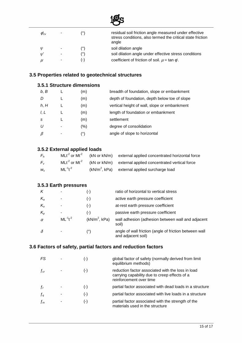
φ'cv - (°) residual soil friction angle measured under effective stress conditions, also termed the critical state friction angle
ψ - (°) soil dilation angle ψ’ - (°) soil dilation angle under effective stress conditions µ - (-) coefficient of friction of soil. µ = tan φ‘.
3.5 Properties related to geotechnical structures 3.5.1 Structure dimensions
b, B L (m) breadth of foundation, slope or embankment D L (m) depth of foundation, depth below toe of slope
h, H L (m) vertical height of wall, slope or embankment l, L L (m) length of foundation or embankment
s L (m) settlement U - (%) degree of consolidation
β - (°) angle of slope to horizontal 3.5.2 External applied loads
Fh MLt-2 or Mt-2 (kN or kN/m) external applied concentrated horizontal force
Fv MLt-2 or Mt-2 (kN or kN/m) external applied concentrated vertical force ws ML-1t-2 (kN/m2, kPa) external applied surcharge load
3.5.3 Earth pressures
K - (-) ratio of horizontal to vertical stress
Ka - (-) active earth pressure coefficient Ko - (-) at-rest earth pressure coefficient
Kp - (-) passive earth pressure coefficient
α ML-1t-2 (kN/m2, kPa) wall adhesion (adhesion between wall and adjacent soil)
δ - (°) angle of wall friction (angle of friction between wall and adjacent soil)
3.6 Factors of safety, partial factors and reduction factors
FS - (-) global factor of safety (normally derived from limit equilibrium methods)
ƒcr - (-) reduction factor associated with the loss in load carrying capability due to creep effects of a reinforcement over time
ƒf - (-) partial factor associated with dead loads in a structure
ƒq - (-) partial factor associated with live loads in a structure
ƒm - (-) partial factor associated with the strength of the materials used in the structure
16 of 17
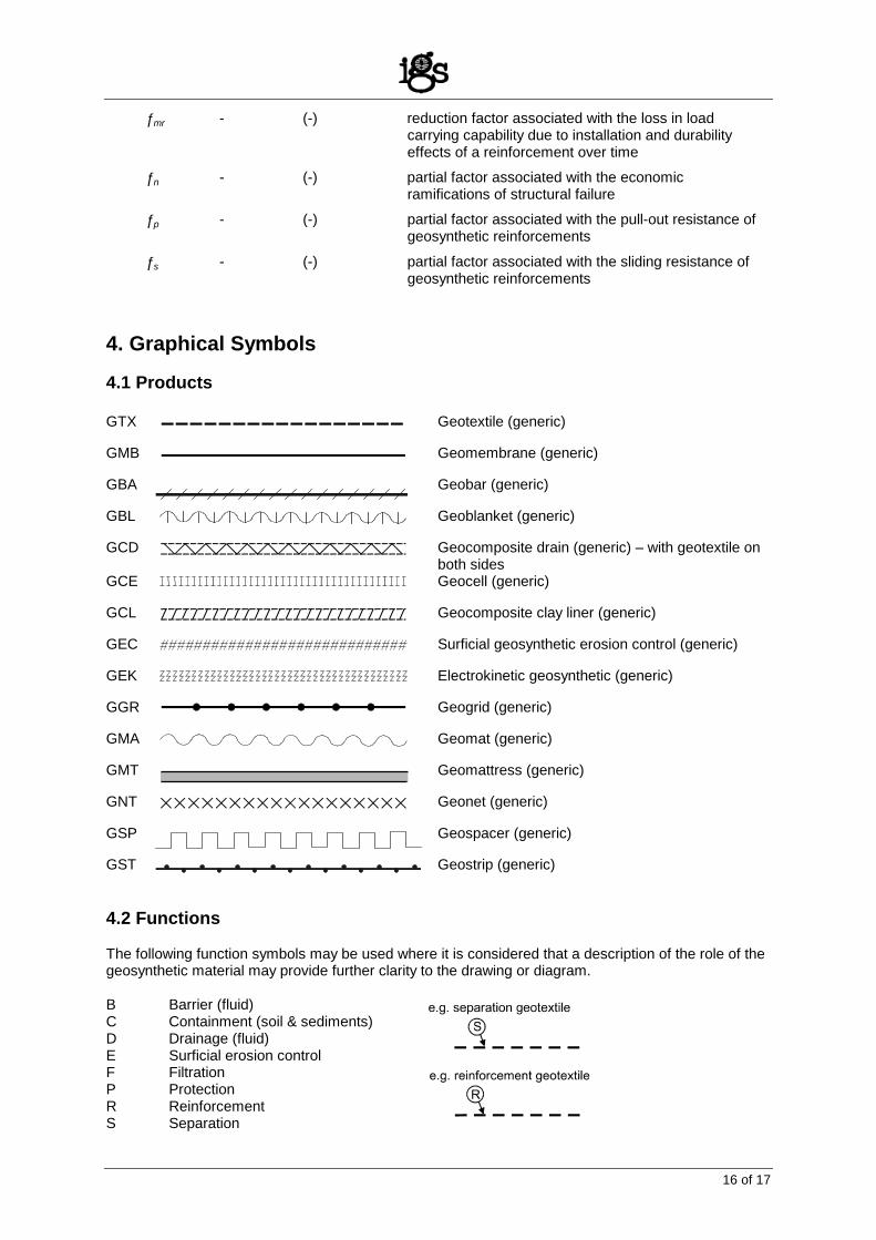
ƒmr - (-) reduction factor associated with the loss in load carrying capability due to installation and durability effects of a reinforcement over time
ƒn - (-) partial factor associated with the economic ramifications of structural failure
ƒp - (-) partial factor associated with the pull-out resistance of geosynthetic reinforcements
ƒs - (-) partial factor associated with the sliding resistance of geosynthetic reinforcements
4. Graphical Symbols 4.1 Products GTX Geotextile (generic)
GMB Geomembrane (generic)
GBA
Geobar (generic)
GBL Geoblanket (generic)
GCD Geocomposite drain (generic) – with geotextile on both sides
GCE Geocell (generic)
GCL Geocomposite clay liner (generic)
GEC Surficial geosynthetic erosion control (generic)
GEK Electrokinetic geosynthetic (generic)
GGR Geogrid (generic)
GMA Geomat (generic)
GMT Geomattress (generic)
GNT Geonet (generic)
GSP Geospacer (generic)
GST Geostrip (generic)
4.2 Functions The following function symbols may be used where it is considered that a description of the role of the geosynthetic material may provide further clarity to the drawing or diagram. B Barrier (fluid) C Containment (soil & sediments) D Drainage (fluid) E Surficial erosion control F Filtration P Protection R Reinforcement S Separation
17 of 17
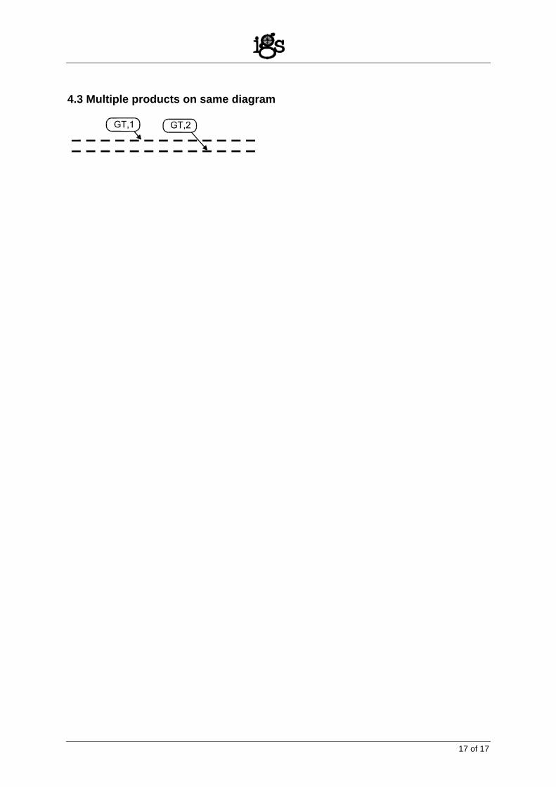
4.3 Multiple products on same diagram