Embed Size (px)
Citation preview

NEW TECHNOLOGY SCOUTING REPORT No. 2/2020 IN THE NEWS TODAY: Reported PI technologies vs products/processes (numbers correspond to news item#)
PRODUCTS & PROCESSES
PI TECHNOLOGIES
Met
al se
para
tion
& re
cove
ry
Desa
linat
ion
Ener
gy st
orag
e
Fine
che
mic
als,
(bio
)pha
rmac
eutic
als
PU re
cycl
ing
Cem
ent,
min
eral
s, st
eel
Trip
heny
lpho
sphi
ne sy
nthe
sis
Was
tew
ater
trea
tmen
t
Enzy
mat
ic o
xida
tions
CO2 t
o fu
els a
nd c
hem
ical
s
Gra
phen
e
Crac
king
Reactive separation 1
Solar processing 2 3 6 14
3D-printing 2
Batch-to-continuous 4 11
Extrusion mixing 5
Electricity-based processing 7 12, 15 16 18
Nanomaterials, MOFs 8, 9
Membrane reactor 10
Micro-/millichannel reactor/separator 19,
20 11 12, 13, 14, 17
Photocatalytic reactor 17

1. Oxidative Precipitation Recovers Nickel and Cobalt from Ore An alternative method for processing mixed nickel-cobalt hydroxide precipitate to separate the nickel from cobalt and manganese has been proposed by a team from the Bandung Institute of Technology (Bandung, Indonesia; www.itb.ac.id), the Indonesian Institute of Sciences (Bandung) and the University of Queensland (Brisbane, Australia). Most existing process plants for nickel laterite ores use intermediate precipitation processes to recover the nickel and cobalt from the leach solution. The precipitation produces an intermediate product of nickel and cobalt, either as mixed sulfide precipitate (MSP) or mixed hydroxide precipitate (MHP), while largely separating nickel and cobalt from impurities such as manganese, calcium and magnesium. Mixed sulfite precipitation processes have a higher selectivity for nickel and cobalt over manganese and magnesium, resulting in a lower level of impurities compared with mixed hydroxide precipitation. However, the operation of sulfide precipitation processes is relatively expensive and complex because they require use of hazardous hydrogen sulfide gas at high temperatures and pressures. The hydroxide precipitation process is, therefore, favorable over sulfide precipitation, especially for simpler processing plants, because it avoids the complexity and capital investment required to recover the nickel and cobalt. The new proposed method comprises a leaching step using sulfuric acid to dissolve the nickel and cobalt from mixed hydroxide precipitates, and subsequently, an oxidative precipitation step to separate the dissolved nickel from cobalt and manganese using ozone as the oxidant. Leaching experiments showed that 97% of the nickel and 96% of the cobalt can be dissolved, while leaving 92% of the manganese in the residue using 1 mol/L sulfuric acid solution at 25°C, a slurry density of 100 g/L and leaching duration of 2.5 h. The results of the oxidative precipitation experiments showed that complete precipitation of the dissolved cobalt and manganese can be achieved by using ozone as oxidant with nickel co-precipitation of about 8.8% at 25°C, equilibrium pH of 5.0, oxidant gas flowrate of 1 L/min and precipitation duration of 2 h. Chemical Engineering, 1 April 2020 2. Sun-Powered Desalination Process that Pumps Ions Instead of Water Researchers from Indonesia’s Bogor Agricultural University (Bogor, Indonesia; www.ipb.ac.id), the University of Bath (U.K.; www.bath.ac.uk), and the University of Johannesburg (Johannesburg, South Africa; www.uj.ac.za), led by Budi Riza Putra, have developed a low-cost, low-energy and low-maintenance, solar-powered desalination system that can be operated in mobile units. The system could service a small number of households, or homesteads in remote locations where freshwater is scarce. The prototype desalination unit is a 3D-printed system with two internal chambers designed to extract or accumulate salt (diagram). When power is applied, salt cations (positively charged ions) and salt anions (negatively charged ions) flow between chambers through arrays of micro-holes in a thin, negatively charged, membrane. The system combines the membrane with an anionic resistor that only allows the flow of negative ions when power is applied. As a result of this one-way flow, salt is
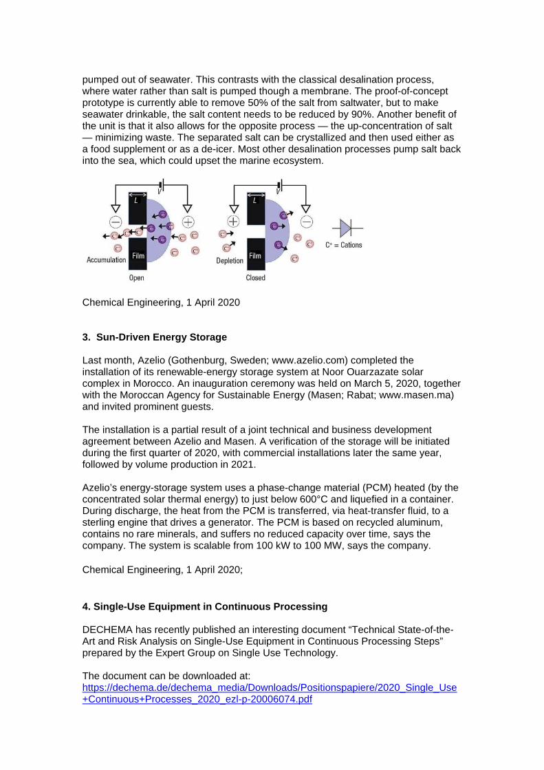
pumped out of seawater. This contrasts with the classical desalination process, where water rather than salt is pumped though a membrane. The proof-of-concept prototype is currently able to remove 50% of the salt from saltwater, but to make seawater drinkable, the salt content needs to be reduced by 90%. Another benefit of the unit is that it also allows for the opposite process — the up-concentration of salt — minimizing waste. The separated salt can be crystallized and then used either as a food supplement or as a de-icer. Most other desalination processes pump salt back into the sea, which could upset the marine ecosystem.
Chemical Engineering, 1 April 2020 3. Sun-Driven Energy Storage Last month, Azelio (Gothenburg, Sweden; www.azelio.com) completed the installation of its renewable-energy storage system at Noor Ouarzazate solar complex in Morocco. An inauguration ceremony was held on March 5, 2020, together with the Moroccan Agency for Sustainable Energy (Masen; Rabat; www.masen.ma) and invited prominent guests. The installation is a partial result of a joint technical and business development agreement between Azelio and Masen. A verification of the storage will be initiated during the first quarter of 2020, with commercial installations later the same year, followed by volume production in 2021. Azelio’s energy-storage system uses a phase-change material (PCM) heated (by the concentrated solar thermal energy) to just below 600°C and liquefied in a container. During discharge, the heat from the PCM is transferred, via heat-transfer fluid, to a sterling engine that drives a generator. The PCM is based on recycled aluminum, contains no rare minerals, and suffers no reduced capacity over time, says the company. The system is scalable from 100 kW to 100 MW, says the company. Chemical Engineering, 1 April 2020; 4. Single-Use Equipment in Continuous Processing DECHEMA has recently published an interesting document “Technical State-of-the-Art and Risk Analysis on Single-Use Equipment in Continuous Processing Steps” prepared by the Expert Group on Single Use Technology. The document can be downloaded at: https://dechema.de/dechema_media/Downloads/Positionspapiere/2020_Single_Use+Continuous+Processes_2020_ezl-p-20006074.pdf

5. New Recycling Method Could Make Polyurethane Materials Sustainable Researchers found a better way to recycle polyurethanes, that could prevent the material from becoming waste. In the past, a few methods have attempted to recycle polyurethane waste, but these techniques result in a material of lower quality. Now, researchers have found a way to recycle used polyurethanes into equivalent or even higher quality material using an innovative method. Their findings are reported in the journal ACS Central Science, published by the American Chemical Society. Conventional polyurethanes can't be simply recycled by heating because the material consists of polymer networks held together by strong chemical bonds that don't flow when heated. Instead, polyurethanes can only be downcycled into less useful materials using either mechanical methods or chemical recycling. Other past methods have made innovative types of polyurethanes with cross-links that can be broken and reformed, allowing it to be recycled. But this approach requires the industry to commercialize new starting materials, and it wouldn't address the issue of conventional waste lingering in landfills. These methods also haven't been tested on foams, a very common form for polyurethane products. In this new study, researchers from the University of Minnesota and Northwestern University ground up polyurethane foam or film and then mixed the particles in a catalyst solution. After drying, the particles were compression molded to form new films. Compression molded films formed good-quality products, but compression molded foam produced cracked and inhomogeneous materials. The researchers solved this problem by developing a twin-screw extrusion process that improved mixing and air removal in recycled foams, compared to the compression molding approach. They say this new method could be used for continuous recycling of the large amounts of polyurethanes waste currently in landfills and newly produced.
https://www.laboratoryequipment.com/563843-New-Recycling-Method-Could-Make-Polyurethane-Materials-Sustainable/ 6. Heliogen Awarded for Unique Solar Technology Heliogen, the clean energy company that is transforming sunlight to replace and create fuels, has recently announced its selection by Fast Company as a recipient of a 2020 World Changing Ideas award. Winning the Energy category, Heliogen was recognised for its technology that – for the first time commercially – replaces fossil fuels with sunlight in a wide range of industrial processes. Heliogen’s technology will deliver carbon-free, ultra-high temperature heat to many industrial facilities, including cement factories, minerals processing plants and steel mills. Differentiating Heliogen’s technology from concentrated solar solutions of the past is its unique use of advanced computer vision software to precisely align an

array of mirrors to reflect sunlight to a single target with unprecedented accuracy. In November 2019, Heliogen announced that it had achieved a record-breaking 1,000 degrees Celsius at its facility in Lancaster, California.
https://www.process-worldwide.com/heliogen-awarded-for-unique-solar-technology-a-928571/?cmp=nl-206&uuid=E1FF1370-FF89-461E-AF7670AA2676CB3D
7. An Efficient Electrochemical Route to Triphenylphosphine — Without the Waste A new electrochemical process could make triphenylphosphine (TPP) — an important reagent in many organic transformations — more practical for industrial use. Synthesizing TPP results in large volumes of waste in the form of triphenylphosphine oxide (TPPO), which is very energy-intensive to handle. Now, a study led by Christo Sevov, professor of chemistry at The Ohio State University (Columbus, Ohio; www.osu.edu), has demonstrated the efficient conversion of TPPO into TPP. Beginning with an electrified aluminum container acting as the anode in an electrochemical cell, the aluminum ions are strategically stripped from the anode surface and then utilized as a Lewis-acid activator for the TPPO. “Everything is self-contained, and because you are using the waste of the anode to activate the substrate, you don’t have to add any super-stoichiometric quantities of reagents, and you continuously generate the activator as you perform the electrochemical reaction,” says Sevov. This continuous generation is key, since this type of reaction normally stalls out after about only 5% completion, shutting down either because the anode is passivated or the selectivity is low. The team has demonstrated this conversion using various aluminum sources — including soda cans and aluminum mesh fencing. This process could also unlock other organic reactions that are not industrially practical.

https://news.osu.edu/scientists-electrify-aluminum-to-speed-up-important-process/ Chemical Engineering, 1 May 2020. 8. MOFs and Nanochannels Enable Lithium Extraction from Brines Traditional methods for obtaining lithium are plagued by poor product recovery (a large portion of Li is lost in the recovery process), slow speed (thermal evaporation of large brine ponds takes months) and poor selectivity (co-precipitation of magnesium makes isolation difficult). Now, development is progressing on a technology that uses metal-organic frameworks (MOFs) embedded inside nanoscale channels in a polymer membrane to selectively separate lithium ions from salt brines. The method is envisioned as a more environmentally friendly lithium-harvesting alternative to conventional methods, such as mining lithium-containing ores and evaporating brine ponds under the sun. Described in a recent paper in Nature Materials, the technique was pioneered by a collaborative team from the University of Texas (Austin), Monash University (Melbourne, Australia) and others, and is licensed for commercialization by Energy Exploration Technologies (EnergyX; Fort Lauderdale, Fla.; www.energyX.com). To make the membrane, nanoscale channels are chemically etched into a thin polymer film, such as polyethylene terephthalate (PET), and filled with UiO-66 MOFs (zirconium oxide nanocrystals). The MOFs form complexes with carboxylic acid groups on the interior surface of the PET nanochannels. A key aspect of the assembly is an asymmetric nanochannel that allows the MOFs to be packed at the smaller end of the channel, while the larger end is open for faster ion transport. The result is ion-sieving action at the MOF end of the channel that is capable of selectively transporting lithium ions. The MOFs can sort ions based on their dehydrated Bohr radius, so the membrane is more permeable for Li ions than for larger ions. Chemical Engineering, 1 May 2020

9. Ion-Exchange Beads for Lithium Extraction A new California-based project launched by Controlled Thermal Resources (CTR; Imperial, Calif.; www.cthermal.com) and Lilac Solutions (Oakland, Calif.; www.lilacsolutions.com) aims to directly extract lithium from geothermal brines that are 4,000 ft below the surface in the Salton Sea Geothermal Field using new ion-exchange (IX) beads. Direct lithium extraction from geothermal brines is a continuous, closed-loop process that returns spent brine to its original source. It has a very small physical footprint, is not weather-dependent and is powered by renewable energy. Adapted from coating techniques used in cathode materials, Lilac Solutions’ IX beads incorporate surface nano-coatings and tailored compositions to selectively absorb Li+ ions from the brine. The Li+ is then released by the addition of acid. Lilac has demonstrated the IX technology in two 1,000-L/h modules on brines including high concentrations of Ca+2 and Li+ concentrations as low as 100 mg/L. Furthermore, the beads’ surface coatings are designed to prevent degradation and enable a long lifecycle. The modular nature of Lilac’s IX technology makes it a good candidate for commercial scaleup — the team has successfully scaled from 1 L/h up to 1,000 L/h over the last 18 months. With startup anticipated later this year, the 1,000-L/h pilot plant with CTR, in concert with Lawrence Berkeley National Laboratory, San Diego State University and Nalco Water, will demonstrate brine pre-treatment alongside Lilac’s IX process to produce high-purity lithium chloride, which will be further processed into lithium hydroxide and lithium carbonate at offsite facilities. CTR was recently awarded a $1.5-million grant from the California Energy Commission to put toward this piloting effort.
Chemical Engineering, 1 May 2020 10. Piloting a New Sewage-Treatment Process to Tackle Emerging Contaminants As new types of water contaminants continue to emerge, such as retinoids and endocrine-disrupting chemicals, wastewater-treatment techniques are evolving to economically handle them. One new process that has shown promise against both conventional and emerging water pollutants integrates two technologies in tandem — chemically enhanced primary sedimentation (CEPS) of sewage and acidogenic fermentation (AF) of sludge. The process, developed by researchers at University of Hong Kong (HKU; www.hku.hk), is being scaled up at a pilot plant in Shenzhen, China, in collaboration with the Nanshan Sewage Treatment Plant. The pilot plant is currently under construction, and is anticipated to start operations and testing within

the next few months. In addition to effective removal of pollutants, the combination of CEPS and AF provides cost benefits in that it enables the recovery of salable materials, including phosphorus and organic compounds. The CEPS portion of the process utilizes an iron flocculant fed alongside raw wastewater. The resulting sludge sidestream is then fed to an acidogenic membrane bioreactor module for organic hydrolysis (as opposed to digestion, as in a conventional sewage-treatment process). Here, a phosphorus product is recovered, and volatile organic acids are extracted back into the process. In laboratory tests comparing the new process to typical sewage-treatment processes, the combination CEPS-AF system generates cleaner effluent — the team reported that 65–80% of retinoids were removed during the CEPS step, with an additional 50% reduction following the AF step, compared to just 57% reduction using traditional treatment methods. The pilot plant will demonstrate the technology’s potential to be retrofitted into existing treatment plants as an add-on module to further enhance the removal of both conventional and emerging pollutants.
Chemical Engineering, 1 May 2020 11. Performance Boost for Enzymatic Oxidations by means of Process Intensification and Continuous Flow Processing O2-dependent biotransformations are promising for chemical synthesis. Their development to the level of efficiency required in fine chemical manufacturing has proven difficult however, due to thermodynamic and kinetic limitations when supplying O2 to the enzymatic reaction creating a complex bottleneck on conversion efficiency using batch technology at atmospheric pressure. Process intensification for oxidative O2-dependent biotransformations is a promising tool using a batch-to-continuous approach. In a cooperation between the Austrian Center of Industrial Biotechnology (ACIB) and Microinnova Engineering GmbH, it was shown that process intensification applying continuous flow technology offers a comprehensive solution. A continuous flow reactor using up to 34 bars enables biotransformations to be conducted in a single liquid phase. Increased enzyme activity has been detected already at 10 bars. For glucose oxidase the intensification factor for enzyme activity was up to 2.5, and amino acid oxidase showed an intensification factor up to 6 for the enzyme activity. High product concentration, with the concentration being 6 to 10 times higher at 34 bars compared to atmospheric pressure has been demonstrated. Reactions of glucose oxidase and amino acid oxidase were used both as soluble enzyme in liquid flow and immobilized enzyme in

a packed bed as exemplary cases to demonstrate that the pressurized continuous flow reactor presents a powerful engineering tool uniquely apt to overcome restrictions inherent to the individual O2-dependent transformation considered. The base for the performance push when using up to 34 bars of pressure is a 34 – 170 fold increase of dissolved oxygen compared to oxygen dissolved at atmospheric pressure. http://www.microinnova.com/index.php/en/about-us/news 12. Green Methanol As part of the “Power-to-Methanol — Green Methanol” project, the Fraunhofer Institute for Solar Energy Systems (Freiburg, Germany; www.ise.fraunhofer.de) recently commissioned a miniplant for synthesizing methanol from H2 and CO2. Featuring a measurement technique with high temporal and spatial resolution, the setup enables research on methanol synthesis, among other things, within the framework of power-to-liquid (PtL) processes on an industrial scale. Here, the main focus of the research is on dynamic reactor operation and unconventional gas compositions using H2 produced by electrolysis and gas streams containing CO2. A number of questions still need to be answered before this process can be implemented on an industrial scale. For example, a high CO2 content in the synthesis gas lead to accelerated aging of the catalyst and to lower chemical yields. Furthermore, fluctuations both in the amount of H2 produced by renewables and in the process for the provision of CO2 may require dynamic synthesis operation. The project is funded by the German Federal Ministry for Economic Affairs and Energy and led by Dechema e. V., with industrial partners CropEnergies AG, Clariant AG and Thyssenkrupp Industrial Solutions AG. Chemical Engineering, 1 June 2020 ------------------------------------------------------------- 13. Modular Power-to-X plants INERATEC GmbH, a spin-off of the Karlsruhe Institute of Technology (KIT), develops innovative reactor technology for modular production of green fuels and chemicals. The chemical reactors by INERATEC are perfectly suitable for the integration into containerized plants. The plants are modular and can therefore be applied to various energy-related sectors. Depending on the application, different reactor systems can be integrated and combined in the plant. The reactors allow a dynamic and load-flexible operation. Short start-up and shut down times make an operation on a decentralized scale attractive. Among processes addressed are steam-assisted catalytic partial oxidation of methane, reverse water gas-shift of CO2 and H2, Fischer-Tropsch synthesis, methanol synthesis and methanation of CO2 and CO.

More recently, INERATEC solutions have become a part of the P2X Kopernikus project oriented on green power storage where fuels of high energy density could be used in a carbon-neutral way. The first liters of fuel were produced from carbon dioxide and green power. For the first time, a container-based test facility integrating all four chemical process steps needed was used to implement a continuous process with maximum carbon dioxide utilization and very high energy efficiency. The existing test facility can produce about 10 liters of fuel per day. In the second phase of the P2X Kopernikus project, it is planned to develop a plant with a capacity of 200 liters per day. After that, a pre-industrial demonstration plant in the megawatt range, i.e. with a production capacity of 1500 to 2000 liters per day, will be designed. That plant may theoretically reach efficiencies of about 60%, which means that 60% of the green power used can be stored in the fuel as chemical energy.
https://ineratec.de/en/carbon-neutral-fuels-from-air-and-electric-power/ 14. Solar Minireactor TNO and Hasselt University have developed one miniscule version of a new kind chemical reactor where sunlight as a direct energy source for chemical processes. The scientists use for this a material developed at Hasselt as a catalyst. The catalyst consists of metals nanoparticles placed in the channels of the reactor, where they absorb the sunlight and convert it very efficiently into the energy that is required to initiate a chemical process. The researchers already succeeded to convert CO2 into methane and the synthesis gas. "In the existing procedures you need to heat the catalyst particles with fossil fuel to a high temperature, with this new process can do the same without the intermediate step, at a low temperature and with sunlight as an energy source”, says Marlies Van Bael of Hasselt University. The innovation is currently at TRL (Technology Readiness Level) 4. The researchers hope within a year or two, three to progress to TRL 5 or 6. Chemie Magazine, 62 (3), March 2020.

15. Consortium Develops Power to Methanol Demonstration Project A consortium of seven companies is collaborating on a demonstration plant to produce sustainable methanol for use by chemical companies in Antwerp, Belgium. In this first of its kind project for Belgium, the planned demonstration plant could produce up to 8,000 t/y of methanol, saving at least 8,000 t/y of CO2 emissions. The Power to Methanol project will produce methanol using captured CO2 and hydrogen (H2) generated using renewable energy. Carbon capture and utilisation will enable partial recovery of CO2 emissions. For each tonne of methanol produced, at least one tonne of CO2 emissions would be avoided. The consortium is conducting a joint feasibility study ahead of committing to the construction of an 8,000 t/y demonstration plant. If successful, a plant would be built at Inovyn’s chemical manufacturing complex at Lillo in Antwerp. Consortium partner Inovyn is a chemical manufacturing company owned by Ineos. In addition to a site for the plant, Inovyn will provide its expertise in hydrogen production and electrolysis. Hydrogen can be produced via electrolysis of water, a process which uses electricity to split water into H2 and oxygen. For renewable production, the electricity is produced using renewable energy sources. Construction of the plant is scheduled to begin in 2022. Government-owned investment company Flemish Environmental Holding (VMH) is a partner is the consortium and will contribute financing to the project. The other partners in the consortium are French electric utility company ENGIE; Indavar, which operates specialist facilities and smart systems for waste management; Oiltanking, which provides tank storage logistics services; independent gas infrastructure group Fluxys; and the Port of Antwerp, Europe’s second largest port.
https://www.thechemicalengineer.com/news/consortium-develops-power-to-methanol-demonstration-project/

16. Green Process Converts Almost Any Carbon Source into Graphene Researchers at Rice University, US, have discovered a green process which can quickly and cheaply produce graphene from almost any carbon source. It could facilitate a reduction in the environmental impact of concrete and other building materials. The process discovered at Rice employs flash Joule heating, which passes an electric current through a conductor to produce heat. Using a custom reactor, the Rice researchers can produce graphene in 10 ms. The carbon source is placed between two electrodes and 200 V is applied in a short electrical pulse, heating the material to more than 3,000 K (2726.9°C). Non-carbon elements sublime and the remaining carbon atoms reconstruct into carbon. In the flash process, the heat is concentrated in the carbon source. Though the internal temperature exceeds 3,000 K, the external walls of the quartz tubes are less than 60°C following the flash process, and all the excess energy comes out as light in a very bright flash. The source material can be anything with carbon content, such as food waste, plastic waste, petroleum coke, coal, wood clippings, and biochar. The flash process would be much cheaper than the conventional process, whilst helping to manage waste. The Chemical Engineer, April 2020. 17. Photocatalytic Microreactors for ‘Green’ Hydrogen Researchers at the University of Southampton, UK, have developed photocatalytic microreactors that convert water into hydrogen fuel using solar energy. The photocatalytic microreactors were made using microstructured optical fibre canes (MOFCs). To enable hydrogen production, the researchers employed a palladium/titanium dioxide catalyst. MOFCs were coated internally and externally using a suspension of titanium dioxide (TiO2) nanopowder in water, and then palladium (Pd) nanoparticle deposited onto the fibre. The MOFCs were developed as high-pressure microfluidic reactors, each housing multiple capillaries that pass a chemical reaction along the length of the cane. They simultaneously serve as both host and catalyst for continuous, indirect water splitting, in which methanol serves as a “sacrificial” reagent. Despite the low loading of the MOFC systems (<0.1 wt%), the researchers achieved hydrogen production efficiency of 70.4 mL/h/g of catalyst. This surpasses analogous liquid-phase powdered systems (14 mL/h/g of catalyst) by a factor of five. H2 and CO2, the products of the reaction, are generated with a 3:1 stoichiometric ratio, which is an improvement upon conventional hydrogen production methods. Alongside hydrogen production, the team are also investigating photochemical conversion of CO2 into synthetic fuel. The technology will require expanded testing, and scale-up into pilot process to confirm the lifetime of the catalyst inside the MOFC. The Chemical Engineer, June 2020

18. Dow Partners with Shell to Develop E-Cracker Technology Dow and Shell have recently announced a joint development agreement to accelerate technology to electrify ethylene steam crackers, which supply chemicals used to make products that people use every day. Today’s steam crackers rely on fossil fuel combustion to heat their furnaces, making them CO2 intensive. As the energy grid becomes increasingly renewables led, using renewable electricity to heat steam cracker furnaces could become one of the routes to decarbonise the chemicals industry. The challenge is to develop a technologically and economically feasible solution. The collaboration between the two companies is already underway and brings together their complementary expertise and common commitment to a low carbon future. Innovation project teams located in Amsterdam, Terneuzen, the Netherlands, and Texas, U.S., are focused on designing and scaling ‘e-cracker’ technologies. They will work in the coming years to first prove out process technology innovations in laboratory and pilot operations and to then scale to commercial crackers. https://www.process-worldwide.com/dow-partners-with-shell-to-develop-e-cracker-technology-a-941119/ 19. Corning launches 10,000 metric tons per year G5 Reactor Corning Incorporated recently announced that its Advanced-Flow™ Reactors (AFR) business has made significant progress advancing its flow reactor technology for large-scale industrial production of chemicals and active pharmaceutical ingredients. Zhejiang Weihua New Materials Co., Ltd. (Weihua) specializes in the research, development, and production of chlorotoluene and trifluoromethyl benzene series products for global pesticide and pharmaceutical enterprises. Weihua recently collaborated with Corning Advanced-Flow Reactor Technology Co., Ltd, and Shanghai Hybrid-Chem Technology Co., Ltd. to achieve 10,000 metric tons annual throughput with Corning’s new G5 reactor for large-scale agrochemical production. This represents the highest production capacity achieved to-date using Corning AFR Technology on a single production line. Weihua currently has two continuous production lines in operation using Corning’s G5 reactors. The lines have been running steadily since November 2019, resulting in:
• Seamless Scale-up from lab (G1 reactor) to mass large-scale industrial production (G5 reactor)
• Higher yield, less waste and better economic benefits • Inherently safer production – the liquid holding capacity of diazotization
reaction was reduced by • 99.99%, and the liquid holding capacity of hydrolysis reaction was reduced by
96.47% • More efficient in space and labor
https://www.corning.com/cala/en/innovation/corning-emerging-innovations/advanced-flow-reactors/industrial-progress-g5-reactor-launch-ccin.html

20. Multiphase Microchannel Separation In conventional two-phase separation, mass transport between two phases can be intensified via increased surface area, usually in the form of smaller droplets or bubbles. The increase in the interfacial surface area typically results in higher energy cost due to agitation, slower processing time for gravity separation, or increased energy requirements through centrifugal extraction. To address these challenges in two-phase separation, RAPID member Oregon State University is developing a flexible yet standardized platform for multiphase separation utilizing microchannel processing technology (MPT). Multiphase Microchannel Separation in MPT systems directs the flow of each phase by creating a capillary force gradient via size and spacing of micro-scale architectural features, thereby controlling capillary forces. With the proper choice of surface properties, the system is designed to guide the fluid via capillary forces towards a selected outlet stream. This technology has already shown a several hundred-fold increase in mass transfer coefficient, resulting in a faster process time, a higher throughput per unit, and will allow the hardware to be significantly smaller and less expensive to produce. RAPID is interested in this technology for its potential to improve energy efficiency and reduce the size and cost of Liquid-Liquid Extraction (LLE). LLE plays a standard role in many chemical and pharmaceutical industries, for example, acetic acid production, biofuels production, and metal production/recovery.
https://www.aiche.org/rapid/news/06-24-2020/rapid-project-spotlight-multiphase-microchannel-separator#:~:text=Multiphase%20Microchannel%20Separation%20in%20MPT,features%2C%20thereby%20controlling%20capillary%20forces.

PATENT HIGHLIGHTS: Annular Divided Wall Column with Ring Shaped Collectors and Distributers Publication number: US2020149810 (A1) Publication date: 2020-05-14 Inventor(s): SABODA KEVIN J [US]; BELANGER PAUL W [US]; LENZ RICHARD D [US]; LARSON KIRK F [US]; BROWN STEVEN C [US]; RICOTTA JOHN P [US]; CHEN GUANG X [US]; FAUST JEREMY D [US] Applicant(s): SABODA KEVIN J [US]; BELANGER PAUL W [US]; LENZ RICHARD D [US]; LARSON KIRK F [US]; BROWN STEVEN C [US]; RICOTTA JOHN P [US]; CHEN GUANG X [US]; FAUST JEREMY D [US] An annular divided wall column for the cryogenic rectification of air or constituents of air is provided. The annular divided wall column includes a first annular column wall and a second annular column wall disposed within the first annular column wall to define an annulus column region and an interior core column region. The present annular divided wall column further includes structured packing elements disposed within at least the annulus column region as well as a ring-shaped cantilevered collector; and a ring-shaped distributor disposed in the annulus column region above or below the plurality of structured packing elements. The thermal expansion and contraction of the second annular column wall in a radial direction and in an axial direction is independent of the thermal expansion and contraction of the first annular column wall in the radial and axial directions. Catalyst, Catalyst Carrier or Absorbent Monolith of Stacked Strands Publication number: WO2020094570 (A1) Publication date: 2020-05-14 Inventor(s): WALSDORFF CHRISTIAN [DE]; KENNEMA MARCO OSKAR [DE]; ROMERO VALLE MIGUEL ANGEL [DE]; SCHARF FLORIAN [DE]; HENSEL DIRK [DE]; ZUEHLKE JUERGEN [DE]; BORNINKHOF FRED [NL]; MICHIELSEN BART [BE]; LEFEVERE JASPER [BE] Applicant(s): BASF SE [DE]; VITO NV [BE] A three-dimensional porous catalyst, catalyst carrier or absorbent monolith of stacked strands of catalyst, catalyst carrier or absorbent material, composed of alternating layers of linear spaced-apart parallel strands, wherein the strands in alternating layers are oriented at an angle to one another, wherein the distance between inner spaced-apart parallel strands is larger than the distance between outer spaced-apart parallel strands in at least a part of the layers of the monolith.

Catalyst Structure for Syngas Production, Syngas Production Device Provided with Said Catalyst Structure for Syngas Production, And Production Method of Catalyst Structure for Syngas Production Publication number: EP3632544 (A1) Publication date: 2020-04-08 Inventor(s): MASUDA TAKAO [JP]; NAKASAKA YUTA [JP]; YOSHIKAWA TAKUYA [JP]; KATO SADAHIRO [JP]; FUKUSHIMA MASAYUKI [JP]; TAKAHASHI HIROKO [JP]; BANBA YUICHIRO [JP]; SEKINE KAORI [JP] Applicant(s): FURUKAWA ELECTRIC CO LTD [JP] Provided are a structured catalyst for synthetic gas production that suppresses the decline in catalytic activity and allows efficient production of a synthetic gas containing carbon monoxide and hydrogen; and a synthetic gas producing device including the structured catalyst for synthetic gas production. The structured catalyst for synthetic gas production (1) of the present invention is a structured catalyst (1) used for producing a synthetic gas containing carbon monoxide and hydrogen and includes a support (10) of a porous structure composed of a zeolite-type compound and at least one catalytic substance (20) present in the support (10), the support (10) has channels (11) connecting with each other, and the catalytic substance (20) is made of metal nanoparticles and is present at least in the channels (11) of the support (10). Modular Microfluidic Device for Mirco-Mixing Fluids Publication number: WO2020104786 (A1) Publication date: 2020-05-28 Inventor(s): BANDULASENA MONALIE VINDYA [GB]; BENYAHIA BRAHIM [GB]; VLADISAVLJEVIC GORAN T [GB] Applicant(s): UNIV LOUGHBOROUGH [GB] This invention provides a microfluidic attachment member, comprising: a channel configured to support a capillary tube and configured to be removably coupled to a further attachment member to assemble a microfluidic module, wherein when the attachment member is coupled to another attachment member, the channels co- axially align so that they can hold an outer capillary tube. The invention also provides a system comprising microfluidic members and methods of micromixing and droplet generation.

Addressable Micro-Reaction Chamber Array Publication number: WO2020126985 (A1) Publication date: 2020-06-25 Inventor(s): PEUMANS PETER [BE]; TAHER AHMED [BE]; VERGAUWE NICOLAS [BE]; JONES BENJAMIN [BE] Applicant(s): IMEC VZW [BE]; UNIV LEUVEN KATH [BE] The present invention provides a micro-reactor (1) adapted to host chemical reactions having at least one microfluidic layer, said micro-reactor (1) comprising a fluid inlet (2) and a fluid outlet (3); a plurality of micro-reaction chambers (10) arranged in rows (7) and columns (6), each micro-reaction chamber comprising a chamber inlet (10a) and a chamber outlet (10b); a plurality of supply channels (4) for supplying fluid to from said fluid inlet (2) to said micro-reaction chambers (10) and further arranged for draining said micro-reaction chambers (10) to said fluid outlet (3), said supply channels (10) extending in a first direction (D1) along the columns (6) of micro-reaction chambers (10) and arranged such that there is one supply channel (4) between adjacent columns (6). The micro-reaction chambers (10) in the columns (6) are arranged such that the chamber inlets (10a) of a column are in fluid contact with the same supply channel (4) and the chamber outlets (10b) are in fluid contact with the supply channel (4) adjacent to the supply channel (4) arranged in fluidic contact with the chamber inlets (10a). Further, the plurality of supply channels (4) comprises a first end supply channel (4a) arranged for supplying fluid to a first end column (6a) of the micro-reaction chambers (10) and a second end supply channel (4b) arranged for draining fluid from the second, opposite, end column (6b) of said micro-reaction chambers (10); and wherein the micro-reactor (1) further comprises at least one reagent inlet (8) in fluid contact with the first end supply channel 4a and a reagent outlet (9) in fluid contact with the second end supply channel such that reagents introduced to the at least one reagent inlet (8) fill the plurality of micro-reaction chambers (10) in a second direction (D2) along the rows (7) of micro- reaction chambers (10) to the reagent outlet (9). Fractal Heat Transfer Device Publication number: US2020149832 (A1) Publication date: 2020-05-14 Inventor(s): POLTORAK ALEXANDER [US] Applicant(s): FRACTAL HEATSINK TECH LLC [US] A heat sink comprising a heat exchange device having a plurality of heat exchange elements each having a surface boundary with respect to a heat transfer fluid, having a fractal variation therebetween, wherein the heat transfer fluid is induced to flow with
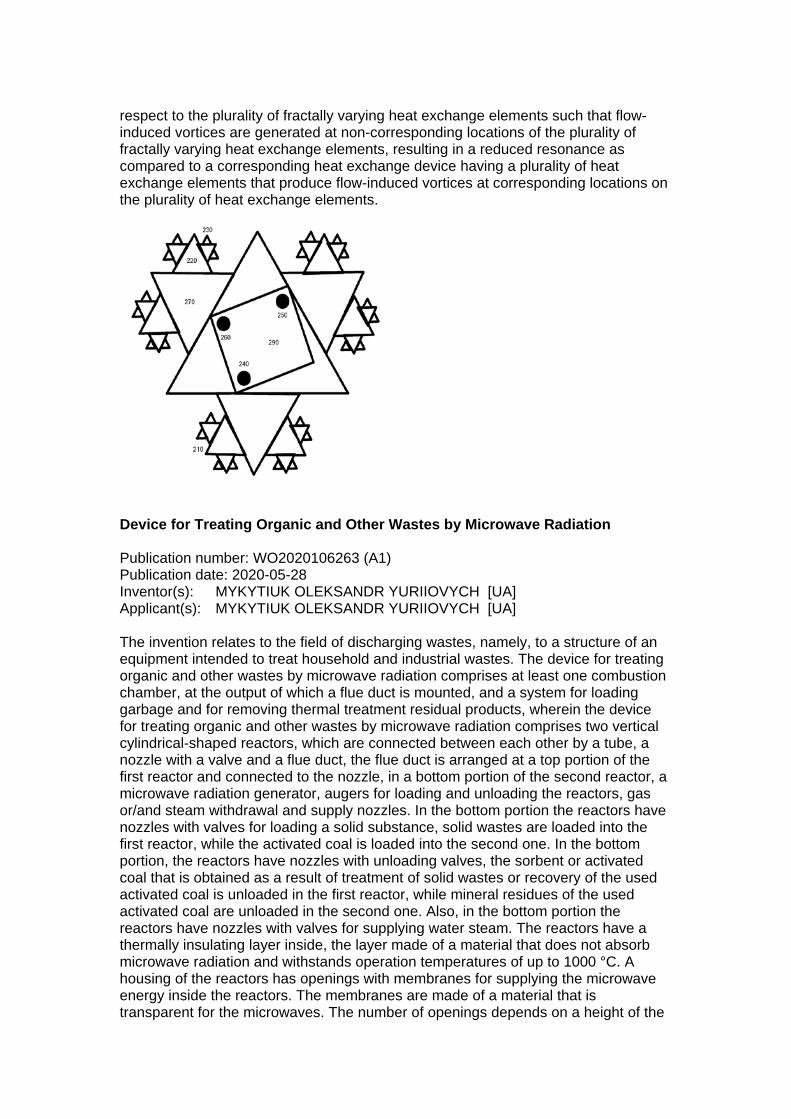
respect to the plurality of fractally varying heat exchange elements such that flow-induced vortices are generated at non-corresponding locations of the plurality of fractally varying heat exchange elements, resulting in a reduced resonance as compared to a corresponding heat exchange device having a plurality of heat exchange elements that produce flow-induced vortices at corresponding locations on the plurality of heat exchange elements.
Device for Treating Organic and Other Wastes by Microwave Radiation Publication number: WO2020106263 (A1) Publication date: 2020-05-28 Inventor(s): MYKYTIUK OLEKSANDR YURIIOVYCH [UA] Applicant(s): MYKYTIUK OLEKSANDR YURIIOVYCH [UA] The invention relates to the field of discharging wastes, namely, to a structure of an equipment intended to treat household and industrial wastes. The device for treating organic and other wastes by microwave radiation comprises at least one combustion chamber, at the output of which a flue duct is mounted, and a system for loading garbage and for removing thermal treatment residual products, wherein the device for treating organic and other wastes by microwave radiation comprises two vertical cylindrical-shaped reactors, which are connected between each other by a tube, a nozzle with a valve and a flue duct, the flue duct is arranged at a top portion of the first reactor and connected to the nozzle, in a bottom portion of the second reactor, a microwave radiation generator, augers for loading and unloading the reactors, gas or/and steam withdrawal and supply nozzles. In the bottom portion the reactors have nozzles with valves for loading a solid substance, solid wastes are loaded into the first reactor, while the activated coal is loaded into the second one. In the bottom portion, the reactors have nozzles with unloading valves, the sorbent or activated coal that is obtained as a result of treatment of solid wastes or recovery of the used activated coal is unloaded in the first reactor, while mineral residues of the used activated coal are unloaded in the second one. Also, in the bottom portion the reactors have nozzles with valves for supplying water steam. The reactors have a thermally insulating layer inside, the layer made of a material that does not absorb microwave radiation and withstands operation temperatures of up to 1000 °C. A housing of the reactors has openings with membranes for supplying the microwave energy inside the reactors. The membranes are made of a material that is transparent for the microwaves. The number of openings depends on a height of the

reactor. The microwave energy is supplied to each reactor through the openings with membrane from the generators or through wave guides. In the top portion the reactors have nozzles with valves for withdrawing gases, with the flue duct or another device that evacuates gases from the reactors. The nozzles of the flue ducts of the reactors are connected between each other and to a nozzle of a heat exchange apparatus. Evacuation of gaseous products from the first reactor is provided by operation of the corresponding device for pumping hot gases and a perforated tube that is arranged inside the first reactor coaxially with the reactor relative to a center thereof and connected to the nozzle for evacuating gases from the first reactor. The perforated tube is made of a heat resistant material that does not react with the microwave radiation, e.g., of titanium or appropriate ceramics. The nozzle for withdrawing gases, in the top portion of the second reactor, is connected through the heat exchange apparatus to a gas compressor and to a gas holder. In the process of treatment of organic and other wastes by the microwave radiation, sorbents for cleaning water from petroleum and petroleum products, saturated and non-saturated fats, or activated coal, and synthetic gas (CO, H2) are formed, as well as conversion of carbon dioxide that is a main component of smoke gases into a syngas that is used as a fuel for generating thermal and electrical energy or/and a raw material for chemical industry. Composite Materials Systems Publication number: US2020172705 (A1) Publication date: 2020-06-04 Inventor(s): STOWELL MICHAEL W [US]; ANZELMO BRYCE H [US]; LANNING BRUCE [US]; COOK DANIEL [US]; ROGOJINA ELENA [US]; VANHUESDEN KAREL [US]; HINES MARGARET [US]; BALDWIN JOHN [US]; KC CHANDRA B [US] Applicant(s): LYTEN INC [US] Methods include producing tunable carbon structures and combining carbon structures with a polymer to form a composite material. Carbon structures include crinkled graphene. Methods also include functionalizing the carbon structures, either in-situ, within the plasma reactor, or in a liquid collection facility. The plasma reactor has a first control for tuning the specific surface area (SSA) of the resulting tuned carbon structures as well as a second, independent control for tuning the SSA of the tuned carbon structures. The composite materials that result from mixing the tuned carbon structures with a polymer results in composite

materials that exhibit exceptional favorable mechanical and/or other properties. Mechanisms that operate between the carbon structures and the polymer yield composite materials that exhibit these exceptional mechanical properties are also examined. Gas/Liquid Plasma Reactor with Pulsed Power Supply and Secondary Direct Current Electrodes Publication number: US2020102231 (A1) Publication date: 2020-04-02 Inventor(s): LOCKE BRUCE R [US]; WANDELL ROBERT J [US]; TANG YOUNENG [US] Applicant(s): UNIV FLORIDA STATE RES FOUND [US] A reactor system for reacting liquid phase chemical species in a liquid includes a reactor vessel for containing the liquid phase and a gas phase. The reactor vessel can have a gas injection port, a gas exit port, and a liquid-gas interface location within the reactor vessel. A pulsed discharge cathode and anode are provided for creating a pulsed discharge electric field at the liquid-gas interface location. A pulsed discharge power supply delivers a pulsed power input to the pulsed discharge cathode and anode, and thereby creates a plasma comprising ions at the liquid-gas interface location. A secondary electric field source is provided for directing a secondary electric field transverse to the liquid-gas interface. The secondary electric field will drive some of the ions from the gas phase into the liquid phase to react with the liquid phase chemical species. A method for reacting a liquid phase chemical species is also disclosed.
Supercritical CO2 Cycle Coupled to Chemical Looping Arrangement Publication number: US2020123935 (A1) Publication date: 2020-04-23 Inventor(s): YOUNES MOURAD [SA]; HARALE AADESH [SA]; JAMAL AQIL [SA] Applicant(s): SAUDI ARABIAN OIL CO [SA] Systems and methods for coupling a chemical looping arrangement and a supercritical CO2 cycle are provided. The system includes a fuel reactor, an air reactor, a compressor, first and second heat exchangers, and a turbine. The fuel reactor is configured to heat fuel and oxygen carriers resulting in reformed or

combusted fuel and reduced oxygen carriers. The air reactor is configured to re-oxidize the reduced oxygen carriers via an air stream. The air stream, fuel, and oxygen carriers are heated via a series of preheaters prior to their entry into the air and fuel reactors. The compressor is configured to increase the pressure of a CO2 stream to create a supercritical CO2 stream. The first and second heat exchangers are configured to heat the supercritical CO2 stream, and the turbine is configured to expand the heated supercritical CO2 stream to generate power. In-Process Ultrasonic Polling Of 3D Printed Crystalline/Semi-Crystalline Electroactive Polymers Publication number: US2020189188 (A1) Publication date: 2020-06-18 Inventor(s): HSU KENG [US]; TOFANGCHI ALIREZA [US]; BERFIELD TOM [US] Applicant(s): UNIV LOUISVILLE RES FOUND INC [US] Methods and systems for producing a structure having selectable piezoelectric properties via additive manufacturing. Such methods can include coupling an ultrasound generating device to a print head of the additive manufacturing apparatus; transmitting acoustic energy from the ultrasound generating device to the print head to vibrate the print head in an oscillatory manner; extruding a feed material from the print head; moving the print head in at least one dimension relative to a substrate on which the structure is being manufactured; and dispensing layers sequentially on top of each other to form the structure. Such systems can include an additive manufacturing apparatus comprising a print head movable in at least one dimension relative to a base configured to support the structure being produced; and an ultrasound generating device that is connected to the print head.
Method of Electro-Hydrodynamic Processing of Hydrocarbon Substances and The Facilities for Its Implementation Publication number: US2020120764 (A1) Publication date: 2020-04-16 Inventor(s): PRUTKOVSKY ALEXANDER [US]; NOVIKOV ILIA [RU] Applicant(s): PRUTKOVSKY ALEXANDER [US]; NOVIKOV ILIA [RU]

The method of electro-chemical processing of hydrocarbon substances, which includes the stage of conversion of those substances in a mixture with water or electrolyte solution by means of its processing with variable electric current. An electro-chemical processing is carried out by a two-stage treatment, comprising a primary electro-hydrodynamic processing by means of an exposure to high voltage, short-pulse electric current discharges of variable frequency, and also comprising the main electro-hydrodynamic processing, carried out in strongly whirling counterflows of the mixture, in the field with a high radial pressure gradient, by exposing the substance to an intensive cavitation, highly developed turbulence, acoustic pressure vibrations, high-frequency alternating electromagnetic field and secondary short-circuited electric currents induced in the conductive mixture, along with a simultaneous separation of the substances formed. The device for electro-hydrodynamic processing of hydrocarbon substances, containing a block for primary electro-hydrodynamic mixture processing is also described and claimed.
A System, Method and Generator for Generating Nanobubbles Or Nanodroplets Publication number: GB2578105 (A) Publication date: 2020-04-22 Inventor(s): MOHAMMAD REZA GHAANI [IE]; NIALL JOSEPH ENGLISH [IE] Applicant(s): UNIV COLLEGE DUBLIN NAT UNIV IRELAND DUBLIN [IE] A method for generating nanobubbles or nanodroplets comprises providing a volume for accommodating a liquid, distributing a medium within the liquid and generating an electric field using an electrode in the proximity of the volume for facilitating the generation of nanobubbles or nanodroplets wherein the electrode and the liquid are not in direct electrical contact to prevent electrolysis occurring within the volume. An apparatus for generating nanobubbles comprises a volume 102 for accommodating a liquid, a source 118 for supplying a medium to the volume for distribution within the liquid and an electrode 104 for generating an electric field in the proximity of the volume to facilitate the generation of nanobubbles and droplet wherein the electrode and the liquid are not in direct electrical contact to avoid electrolysis. The medium may be a gas or liquid. The electrode

ideally consists of a cathode 123 and anode 124 which are coated with an electrically insulating material. The apparatus may comprise cooling means 106, 107, 106. A method of releasing nanobubbles or nanodroplets from a liquid by applying at least one of an acoustic signal or electromagnetic signal to the liquid. Device and Method for The Selective Fractionation of Ultrafine Particles Publication number: US2020108401 (A1) Publication date: 2020-04-09 Inventor(s): FRANZREB MATTHIAS [DE]; EBELER MORITZ [DE]; TSCHOEPE ANDRE [DE] Applicant(s): KARLSRUHER INST TECHNOLOGIE [DE] An apparatus for a selective fractionation of ultrafine particles includes at least three separating columns fluidically connected in series by connecting lines. An infeed is arranged to feed into a connecting line which is arranged upstream of each separating column. Each connecting line comprises an inlet for a suspension of ultrafine particles to be separated and an inlet for at least one additional mobile phase. The inlets are alternately operated. A discharge branches off from a connecting line which is arranged downstream of each separating column. Each connecting line comprises an outlet for a first and a second discharge suspension of the ultrafine particles. The outlets are alternately operated. A control means provides a simultaneous switching of the through-flow switching position of the shutoff valves at the inlets and outlets. At least one magnetic field source for a magnetic field is arranged in each separating column.
High-Efficiency Particle Encapsulation in Droplets with Particle Spacing and Downstream Droplet Sorting Publication number: US2020108393 (A1) Publication date: 2020-04-09 Inventor(s): LEE ABRAHAM P [US]; KAMALAKSHAKURUP GOPAKUMAR [US]; AGHAAMOO MOHAMMAD [US]; LI XUAN [US]; LIN GISELA [US]; LUO XUHAO [US]; ATAEI MARZIEH [US]; DIGMAN MICHELLE A [US]; PALOMBA FRANCESCO [US] Applicant(s): UNIV CALIFORNIA [US] A passive, hydrodynamic technique implemented using a microfluidic device to perform co-encapsulation of samples in droplets and sorting of said droplets is described herein. The hydrodynamic technique utilizes laminar flows and high shear

liquid-liquid interfaces at a microfluidic junction to encapsulate samples in the droplets. A sorting mechanism is implemented to separate sample droplets from empty droplets. This technique can achieve a one-one-one encapsulation efficiency of about 80% and can significantly improve the droplet sequencing and related applications in single cell genomics and proteomics.
Induction Heating System for Molding A Thermoplastic Article and Method for Molding A Thermoplastic Article Publication number: US2020189148 (A1) Publication date: 2020-06-18 Inventor(s): GRAY EVERETTE D [US] Applicant(s): BOEING CO [US] An induction heating system for molding a thermoplastic article includes a first mold and a second mold defining a mold cavity therebetween for molding the thermoplastic article, a first metallic susceptor as part of or adjacent to the first mold, a first armature-supported induction coil array in proximity to the first metallic susceptor, and a first induction generator electrically coupled with the first armature-supported induction coil array.

Devices and Methods for Thin Film Chemical Processing Publication number: AU2018367058 (A1) Publication date: 2020-06-18 Inventor(s): RASTON COLIN; VIMALANATHAN KASTURI; JONES DARRYL BRUCE; ALSULAMI IBRAHIM KHALAF M; ALHARBI THAAR MUQHIM D Applicant(s): 2D FLUIDICS PTY LTD [AU] Producing nanostructure materials in a thin film reactor (TFR) from starting material of inorganic or organic material of layered or two dimensional (2D) structure or inorganic material transformed in situ into 2D inorganic material, or single walled carbon nanotubes (SWCNTs), and a solvent or liquid phase. The TFR can be a vortex fluidic device (VFD) or a device with spaced first and second fluid contact surfaces, which can be conical, for relative rotation to generate shear stress in the thin film therebetween. A liquid supply means delivers a liquid between the first and second fluid contact surfaces. The composition can be exposed to laser energy. The thin film reactor can form graphene, graphene oxide, scrolls, tubes, spheres or rings of the layered or 2D material. An Electrochemical Reactor System Comprising Stackable Reaction Vessels Publication number: WO2020112024 (A1) Publication date: 2020-06-04 Inventor(s): HANDOKO ALBERTUS DENNY [SG]; SEH ZHI WEI [SG] Applicant(s): AGENCY SCIENCE TECH & RES [SG] An electrochemical reactor system comprising stackable reaction vessels is provided herein. Each of the stackable reaction vessels is fillable with an electrolyte and comprises an anode (100), a cathode (102) and an ion selective membrane (106) arranged between the anode (100) and the cathode (102). There is at least one gas sparger disposed across two of the stackable reaction vessels, wherein the two stackable reaction vessels are configured as an upstream stackable reaction vessel and a downstream stackable reaction vessel arranged adjacent to the upstream stackable reaction vessel, wherein the at least one gas sparger comprises (i) a pipe (202) disposed across the two stackable reaction vessels and (ii) a chamber (204) disposed in the downstream stackable reaction vessel, wherein the chamber (204) has an opening and a closed end disposed away from the opening, wherein the pipe (202) extends through the opening toward the closed end to direct gas to form a sparger headspace (206) at the closed end within the chamber (204).

Omniphobic Membranes and Application Thereof Publication number: US2020156006 (A1) Publication date: 2020-05-21 Inventor(s): TUNG KUO-LUN [TW]; HUANG ALLEN [TW]; CHEN LIANG-HSUN [TW]; CHEN YI-RUI [TW]; CHEN CHIEN-HUA [TW]; HSU CHE-CHEN [TW]; TSAI FENG-YU [TW] Applicant(s): UNIV NAT TAIWAN [TW] The present invention provides an omniphobic membrane and application thereof. The omniphobic membrane comprises a porous substrate which has a pore size between 0.4 and 2 μm, a top coat, and an interface layer between the porous substrate and the top coat, and the omniphobic membrane has a carbon/silicon ratio between 40 and 60, and a hierarchical re-entrant structure. Furthermore, both of a process for fabricating the omniphobic membrane and a method for desalination of a liquid by membrane distillation are provided in the present invention. Continuous Crystallization Method Under Control of Multistage Membrane Publication number: US2020114277 (A1) Publication date: 2020-04-16 Inventor(s): JIANG XIAOBIN [CN]; LI GUANNAN [CN]; HE GAOHONG [CN]; TUO LINGHAN [CN]; LU DAPENG [CN]; XIAO WU [CN]; LI XIANGCUN [CN]; WU XUEMEI [CN] Applicant(s): UNIV DALIAN TECH [CN] The present invention provides a continuous crystallization method under control of the multistage membrane modules, and belongs to the technical field of crystallization engineering. A crystallization solution is added to a crystallizer, and a stirring apparatus and a temperature control apparatus are started. After the system running stability, the loop of crystallization is started. Meanwhile, the coolant or antisolvent feed liquid loop is also started. The crystallization solution can respectively conduct crystal nucleation, growth and ripening in the multistage membrane modules, and then the crystallization solution is transported into a filter device and a drying apparatus to obtain the final crystal products. The desired crystal products can be obtained by the systematical control of the nucleation and crystal growth through the flow and the temperature of the crystallization solution, coolant or antisolvent feed liquid, and the contact time between two liquid phases.