Embed Size (px)
Citation preview
New Compressor Technologies for Emissions Reduction in Shale Gas Applications
Natural Gas STAR Implementation Workshop November 2015
Presenters: Joe Baker Jack Schwaller

Summary of the project findings Introduction and Background of this applicationTest methods & Data Collection Pressure Packing & Valve Designs UtilizedStudy ResultsBenefits to Customer & Equipment Owner
2
One or both of these technologies are currently applied in a number of recip. compressor applications in units owned or
leased by Natural Gas Star partners such as DCP Midstream, Targa, EnerVest, Enogex(Enable), Trillium,
Kinder-Morgan and others.
Disclaimer: This test and its conclusions as interpreted by the authors, apply only to this specific field application and equipment.
Project SummaryIn today’s business environment, companies must work smarter, not
harder to maintain profitability and meet environmental regulations.
3
Problem: Shale Gas applications produce heavy liquids & debris, significantly affects compressor life.
reduces efficiency & reliability and thus increases operating cost increased number of shutdowns for valve and packing change-outs
higher costs for more frequent parts replacement , Increased labor
and travel to troubleshoot
increases overall compressor package emissions more compressor blow downs at each shutdown
higher wear rates and rod seal damage = higher GHG and oil leakage
higher HP/mcfd due to valves = higher fuel used = more exhaust
Project Summary - End of 2013, Flatrock commissioned a lifecycle study of (10) GE/Gemini wellhead compressors in the Eagleford Shale (EFS) .
4
Results:
Reduced # unplanned shutdowns/yr 90%
Reduced # replacement valves/yr from 190 to 6. 97%
Reduced # replacement 1-1/8” packings/yr from 31 to 1 97%
Goal: To examine how more durable valves & rod seals can better handle heavy liquids & debris.

Project Summary - cont. Flatrock commissioned study
To measure and reduce compressor natural gas emissions with same technologies
5
Results: Reduced number of blow downs Saves 4.8 Mcf/yr =
*.1 tons CH4/yr Unit Packing average leakage rate reduced 19.5scfh or 156 Mcf/yr ) =
*3.3tons CH4/yr
*Total lost gas $$ savings per Unit @ $3/Mcf =
$468/yr
Used the EPA Methane online calculator. Actual tonnage is higher for this VOC gas. 1 year is 8000 hours

Introduction - Flatrock Compression rents compressors for natural gas wellhead & gathering applications .
6
Their goal is to achieve a 98%+ unit mechanical availability.
maximize run time between scheduled maintenance
minimize number of unscheduled shutdowns.
Produced hydrocarbon market prices down 40+%. Unit providers must work efficiently due to reduced rental rates

Background – Eagleford Shale (EFS)EFS is a highly active shale play in S.Texas. An ideal location for field testing in this light oil window (0.75 to 0.80 SG)
7
Test Area

Background - Gas Lift is used to extract oil and NGL
A gas lift compressor injects natural gas through a tubing-casing annulus to aerate the well fluids and reduce its specific gravity.
The enhanced formation pressure lifts the lighter fluid column and forces it out of the well bore.
High liquid carry-over ingested by the compressor causes internal damage
8
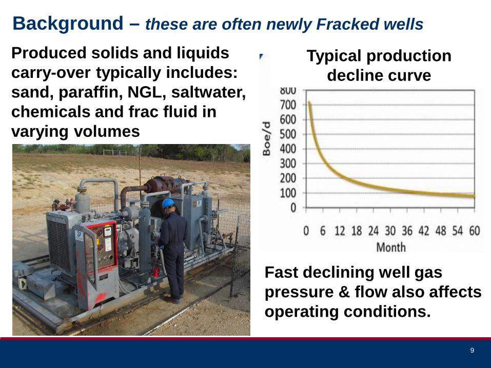
Background – these are often newly Fracked wells
9
Produced solids and liquids carry-over typically includes:sand, paraffin, NGL, saltwater, chemicals and frac fluid in varying volumes
Fast declining well gas pressure & flow also affects operating conditions.
Typical production decline curve
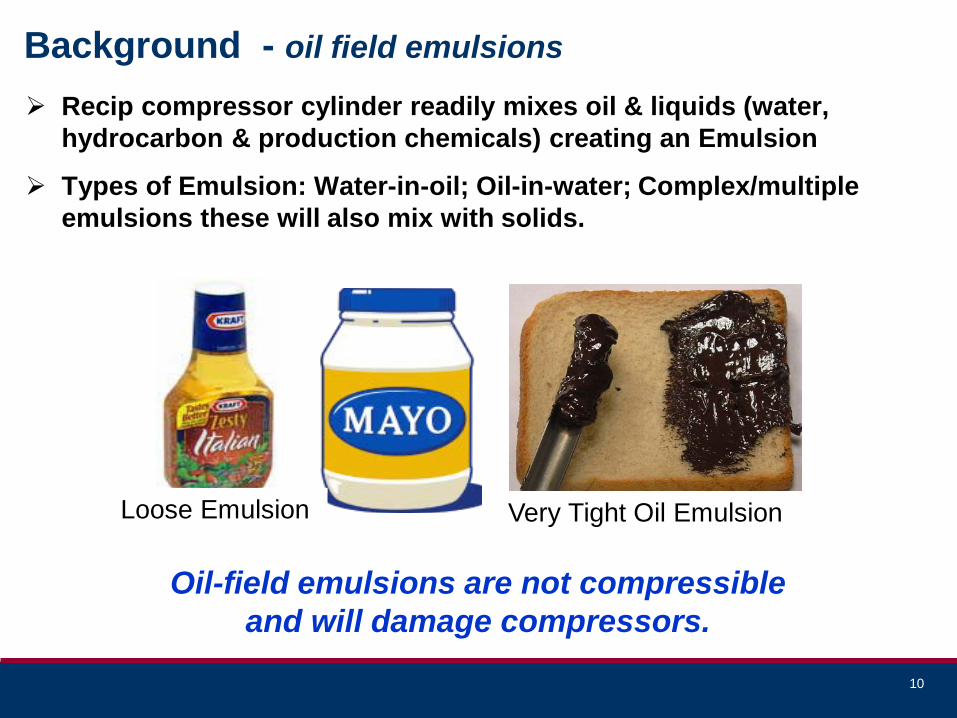
Background - oil field emulsions
Recip compressor cylinder readily mixes oil & liquids (water, hydrocarbon & production chemicals) creating an Emulsion
Types of Emulsion: Water-in-oil; Oil-in-water; Complex/multiple emulsions these will also mix with solids.
10
Very Tight Oil EmulsionLoose Emulsion
Oil-field emulsions are not compressible and will damage compressors.

The study – Ten 3 stage test Compressors
11
Two GE units types: H302 (145hp) & A352 (215 & 325hp)
Pre-test Data maintenance logs, outages, & repair costs reviewed for past 3 years
rod packing emissions tests made on typical units
established O&M cost basis for valves and packing
Testing Team - Flatrock Field techs and Hoerbiger engineers
New Compressor Valves & Rod Packing installed
Nov. 2013, quarterly testing commenced tracking: unit status, the event log and operating conditions
valve cap temperatures taken to determine valve condition
packing case leakage measured
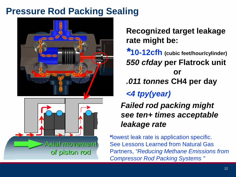
Pressure Rod Packing Sealing
12
Recognized target leakage rate might be:*10-12cfh (cubic feet/hour/cylinder)
550 cfday per Flatrock unit or
.011 tonnes CH4 per day<4 tpy(year)
*lowest leak rate is application specific. See Lessons Learned from Natural Gas Partners, “Reducing Methane Emissions from Compressor Rod Packing Systems "
Failed rod packing might see ten+ times acceptable leakage rate

Upgrades to Flatrock units
13
BCD Ring
H-frame pressure packing case assembly
Increase run time – EPA new limit of 3 years Replace assembly - new or Certified repair Install BCD ring style to improve durability
and last the 3+ years Installed hardened Piston Rod
Train to improve installation methods Requires a proper torquing
of the flange bolts New nose gasket
Gas leakage check
BCD style ring
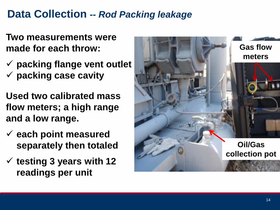
Data Collection -- Rod Packing leakage
14
Oil/Gas collection pot
Gas flow meters
Two measurements were made for each throw: packing flange vent outlet packing case cavity
Used two calibrated mass flow meters; a high range and a low range. each point measured
separately then totaled testing 3 years with 12
readings per unit
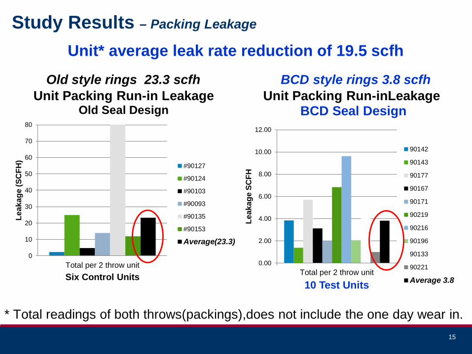
Study Results – Packing Leakage
15
Unit* average leak rate reduction of 19.5 scfh
Old style rings 23.3 scfh BCD style rings 3.8 scfh
* Total readings of both throws(packings),does not include the one day wear in.
0
10
20
30
40
50
60
70
80
Total per 2 throw unit
Leak
age
(SC
FH)
Six Control Units
Unit Packing Run-in Leakage Old Seal Design
#90127
#90124
#90103
#90093
#90135
#90153
Average(23.3)
0.00
2.00
4.00
6.00
8.00
10.00
12.00
Total per 2 throw unit
Leak
age
SCFH
10 Test Units
Unit Packing Run-inLeakageBCD Seal Design
90142
90143
90177
90167
90171
90219
90216
90196
90133
90221
Average 3.8
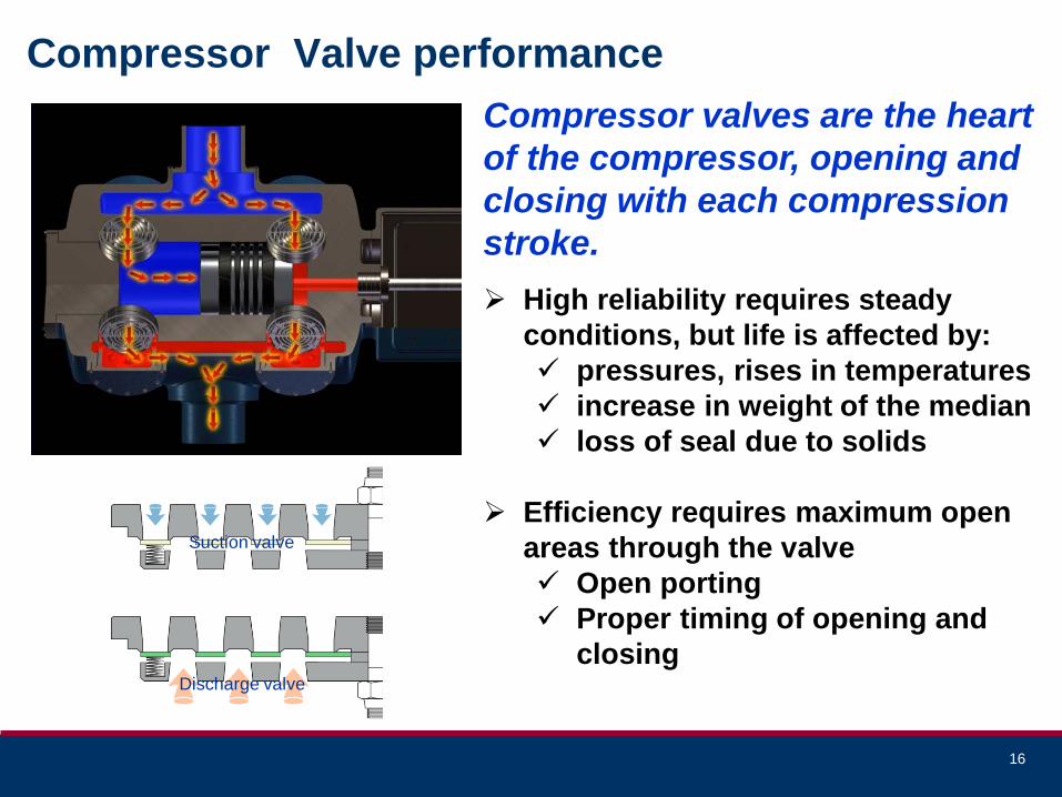
Compressor Valve performance
16
Suction valve
Discharge valve
Compressor valves are the heart of the compressor, opening and closing with each compression stroke. High reliability requires steady
conditions, but life is affected by: pressures, rises in temperatures increase in weight of the median loss of seal due to solids
Efficiency requires maximum open areas through the valve Open porting Proper timing of opening and
closing
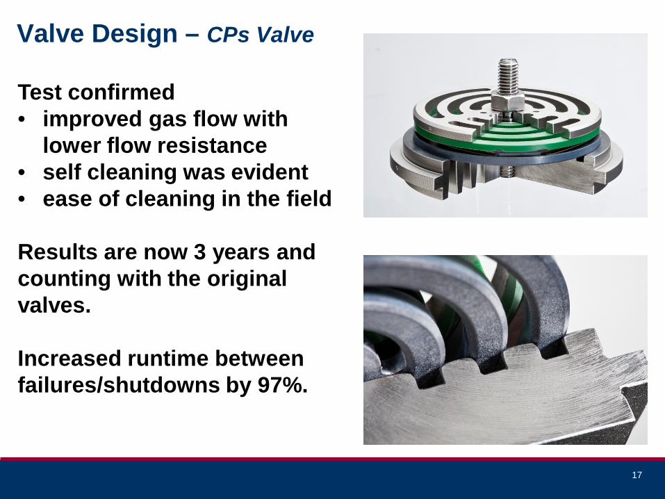
Valve Design – CPs Valve
17
Test confirmed• improved gas flow with
lower flow resistance • self cleaning was evident• ease of cleaning in the field
Results are now 3 years and counting with the original valves.
Increased runtime between failures/shutdowns by 97%.

Annual valve inspections – 2014 & 2015
18
Valve Seat before & after hand clean up
Retainer and valve with paraffin wax buildup
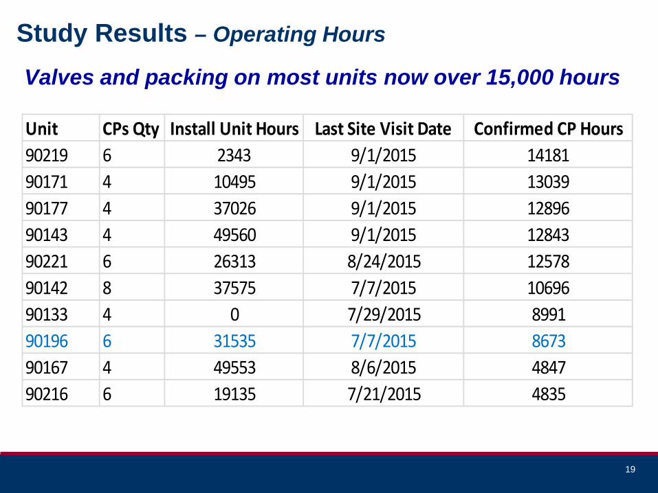
Study Results – Operating Hours
19
Valves and packing on most units now over 15,000 hours
Unit CPs Qty Install Unit Hours Last Site Visit Date Confirmed CP Hours90219 6 2343 9/1/2015 1418190171 4 10495 9/1/2015 1303990177 4 37026 9/1/2015 1289690143 4 49560 9/1/2015 1284390221 6 26313 8/24/2015 1257890142 8 37575 7/7/2015 1069690133 4 0 7/29/2015 899190196 6 31535 7/7/2015 867390167 4 49553 8/6/2015 484790216 6 19135 7/21/2015 4835

Future implementation
20
Based on the program results, the packing and valve replacement is planned for:
1. Any compressor experiencing multiple overload conditions caused by liquid or debris carryover
2. All A352 compressors
Compressor HpRating
New Design Valve & Packing Cost Estimate
Pay back(years)
H302 – 3 stg 145 $7,000 4.8
A352 – 3 stg 215 $9,000 1.8
A352 – 3 stg 325 $14,000 1.4
Summary - Study Results Significant reduction in O&M outages & $/Hp-year for 10
test units’ valves & pressure packing vs standard components.
Greatly extended runtimes are still being experienced.Now exceeding 15,000 run hours
Reduced number of shutdown/blowdowns can add up to high emissions
Pressure packing gas leakage after a short start-up/wear-in dropped from 24 to 3 scfh; a 19.5 reduction in GHG/VOC emissions from one unit!
Valve and packing upgrades are cost affective, especially when addressing “special” situations where liquids & debris common.
21

Benefits to Producer
Increased profitability from consistent and stable process operations.
Reduced engine exhaust and GHG emissions Reduces compliance issues Enhances company GHG reduction goals
Reduced packing leakage keeps more gas & lubricating oil in compressor increases saleable/useable gas, even at 3.00 $/MCFD minimizes the on-site handling/disposal of liquid hydrocarbons
(oil).
Improved equipment reliability provide a better utilization of assets & personnel
22

Benefits to Equipment Owner
Increased profitability from consistent high unit availability
Reduced labor, travel and maintenance costs with longer lasting wear parts.
Low cost retrofit of new technology to existing legacy compressors will give faster paybacks.
Reduced after hour callouts increases profitability and safety.
Improved unit reliability optimizes personnel utilization increasing routine maintenance activities.
An improved overall work environment, gives fewer “surprises” increasing employee morale.
23
Questions?