Embed Size (px)
Citation preview

Future Compressor Station Technologies and Applications
Jason GatewoodSouthwest Research Institute
Feb 9th, 2012Gas Electric Partnership Conference
Overview• Review of Historical Compression Applications• Three compressor station technology/application
trends that may be more prevalent in the future– Technology/application Trend 1: Significant increase
in Waste Heat Recovery– Technology/application Trend 2: Coordinated Energy
Power Systems– Technology/application Trend 3: CO2 compression
using integrated high speed EMD compressors (with an introduction to future CO2 compression needs)

Compression Applications in the US

Oil & Gas Compression US Market• Upstream
– Mostly small high speed separable recips for gas gathering and push compression.
– Some gas turbine’s for pull compressions (typically less than 10kHp)
– Limited electrical infrastructure available• Downstream
– Midsize and large steam turbine driven compressors– Low speed recips– Some gas turbines
• Midstream– 40-50% low speed integral recips– 20-30% industrial and aeroderivative gas turbines– 10-15% high speed separables (both gas engine and electrical)– 5% electric motor driven centrifugals

Map of US Compressor Stations (2008)
Over 900 interstate pipeline compression stations in the US
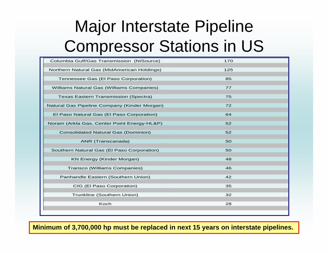
Major Interstate PipelineCompressor Stations in US
Columbia Gulf/Gas Transmission (NiSource) 170
Northern Natural Gas (MidAmerican Holdings) 125
Tennessee Gas (El Paso Corporation) 85
Williams Natural Gas (Williams Companies) 77
Texas Eastern Transmission (Spectra) 75
Natural Gas Pipeline Company (Kinder Morgan) 72
El Paso Natural Gas (El Paso Corporation) 64
Noram (Arkla Gas, Center Point Energy-HL&P) 52
Consolidated Natural Gas (Dominion) 52
ANR (Transcanada) 50
Southern Natural Gas (El Paso Corporation) 50
KN Energy (Kinder Morgan) 48
Transco (Williams Companies) 46
Panhandle Eastern (Southern Union) 42
CIG (El Paso Corporation) 35
Trunkline (Southern Union) 32
Koch 28
Minimum of 3,700,000 hp must be replaced in next 15 years on interstate pipelines.

Pipeline Compression History:Horizontal Compressor
• Original pipeline prime mover first installed in the 1930s.
• Internal combustion spark ignited, four cylinder unit (1700 bhp supercharged) running at 125 rpm.
• Power cylinders are horizontal-opposing.
• Most of these units (Cooper and Worthington) have been replaced with integral horsepower
• Some remain in operation with Tennessee Gas, Northern Natural and Panhandle Eastern.

Pipeline Compression History:Gas Integral Compressors
• Internal combustion, spark ignited, engine driver with integral reciprocating compressor (the engine and compressor share the same crankshaft).
• Majority of these units were installed from the 1950-1970. Integrals are still a workhorse for the natural gas compression industry.
• Units are either 2 or 4 cycle and are typically supercharged. Horsepower ranges 600 - 17,000 bhp.
• Manufacturers have included Cooper-Bessemer, Dresser Rand, Ingersoll Rand, Worthington and Clark.
• Massive in size, complex auxiliary systems, costly to operate.
• Excellent efficiencies above 40%.

Pipeline Compression History:Gas Separable Compressors
• The engine and compressor have individual crankshafts and are coupled as separate devices on a unitized skid.
• Introduced late 1960s and still major market player.
• Initially suffered as they were high speed machines (350 - 1200 rpms) with unacceptable vibrations.
• Recent years made a come back and are now displacing some of the larger integral units.
• Pipelines purchase primarily Ariel Compressors through “packagers”. Other vendors are GE, Cameron, and Dresser.
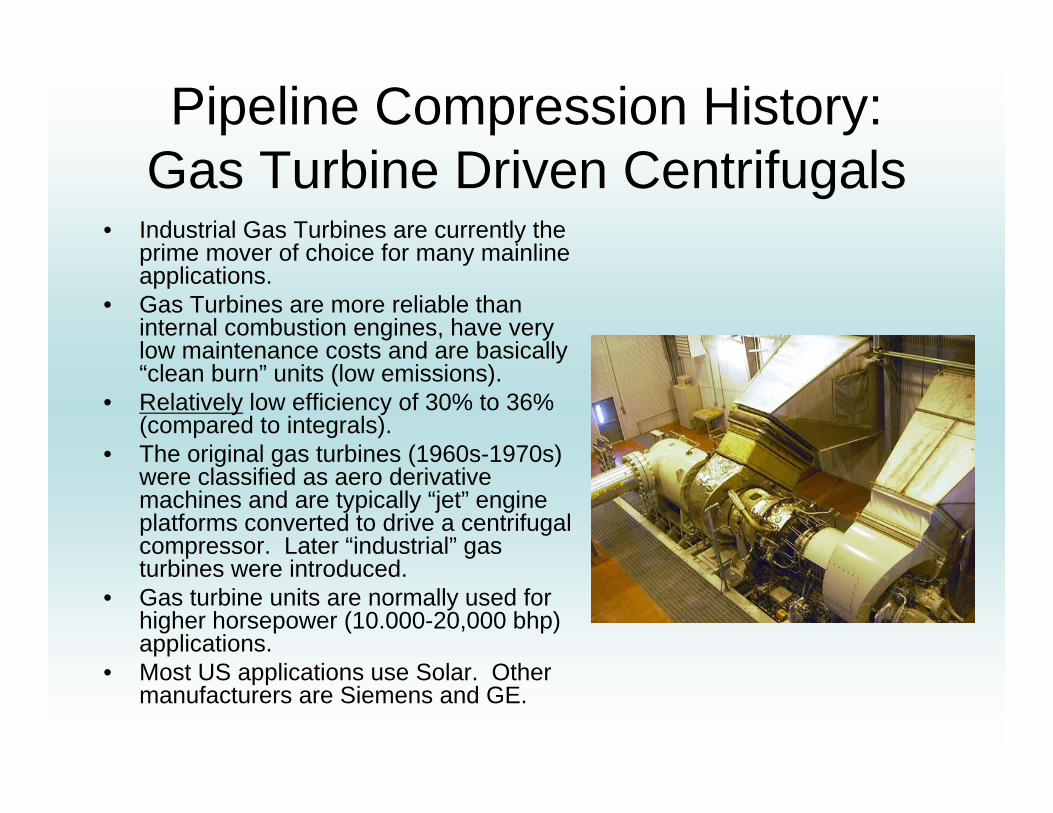
Pipeline Compression History:Gas Turbine Driven Centrifugals
• Industrial Gas Turbines are currently the prime mover of choice for many mainline applications.
• Gas Turbines are more reliable than internal combustion engines, have very low maintenance costs and are basically “clean burn” units (low emissions).
• Relatively low efficiency of 30% to 36% (compared to integrals).
• The original gas turbines (1960s-1970s) were classified as aero derivative machines and are typically “jet” engine platforms converted to drive a centrifugal compressor. Later “industrial” gas turbines were introduced.
• Gas turbine units are normally used for higher horsepower (10.000-20,000 bhp) applications.
• Most US applications use Solar. Other manufacturers are Siemens and GE.

Pipeline Compression History:Other Equipment Configurations
• Fixed Low Speed Electric Reciprocating
• Fixed Medium Speed Electric Reciprocating
• VFD Reciprocating • Conventional Fixed-Speed
Electric Centrifugal • Conventional Fixed Speed
with Voith VoreconHydrodynamic Fluid Coupling
• Conventional Speed VFD-Centrifugal
• Screw compressors and other PD compressors
Voith Vorecon

Pipeline Operating Conditions
25,000
20,000
15,000
10,000
5,000
2,000 3,000 4,000 5,000 6,000INLET VOLUME FLOW
74%
82%
85%
78%
85%82%
86%
Pipeline Resistance Curve
1,000
The operating map based on the design points…
Map courtesy of Solar Turbines

Reality!
-5000
0
5000
10000
15000
20000
25000
30000
35000
40000
0 5000 10000 15000 20000 25000
ACFM
HEAD
(FT)
1 UNIT 2 UNITS 3 UNITS IN PARALLEL
SITE POWER AT 75F
How the compressor ends up operating….
Map courtesy of Solar TurbinesPart Speed and Part Load Operation is Critical

Pipeline Compression Selection Criteria
• Ease of maintenance• Emissions• Operating flexibility and range• Reliability/Availability• Total Installed Cost• Fuel Efficiency• Legislation (particularly for CO2)

Future Pipeline Compression Opportunities
• Numerous technologies available or being developed to address industry needs!
• This presentation only covers a few particularly interesting approaches…other options are certainly feasible! (Disclaimer)
• Three technologies/applications trends that maybe more prevalent in the future– Waste Heat Recovery– Coordinated Energy Power Systems– Use of integrated high speed EMD compressors for
CO2 compression

Technology/Application Trend 1: Significant Deployment of Waste Heat
Recovery

WHR Recent Development Summary
• SwRI conducted industry sponsored research on WHR technology development
• In 2010, 20 small scale WHR concepts for use at a pipeline station were identified
• Initial technical evaluations were completed for each of the 20 concept
• The concepts were ranked based on metrics and pipeline company feedback
• Further analysis was completed on the top 5 concepts

2010 WHR Development Summary
• The top ten WHR concepts based on the scoring matrix are below (bolded concepts were top five selected based on matrix rankings and pipeline company feedback)
1. Process Gas Drying2. Turbine Inlet
Cooling3. Fuel Gas Pre-
Heating4. Electricity Use at
Station (Stacked Rankine)
5. Pipeline Gas Pre-Cooling
6. Heat Storage7. Gas Treatment using
Waste Heat8. Thermoelectrics9. Industrial Process (co-
locating)10.Rankine Cycle for
Added Compression

2011 WHR Project• Objective: Further evaluate and develop 3 WHR concepts
– Pipeline gas cooling– Stacked Rankine Cycle (SRC)– Heat storage
• Pipeline gas cooling and SRC– Develop conceptual design of WHR concepts– Identify commercial equipment which can be used for concept– Complete economic analysis on WHR concept at idealized station
• Heat storage– Evaluate use of different types of thermal energy storage (TES) at
pipeline stations– Identify the TES method that should be used with various WHR
concepts– Design heat storage system which can be used with pipeline gas
cooling concept

Pipeline Gas Cooling –General Concept
• Use waste heat to perform industrial chilling
• Used chilling to cool gas before compression– Lower energy to
compress cooler gas, or
– Compress more gas with same energy

Thermal Energy Storage (TES) -General Concept
• Store thermal energy from gas compression waste heat in the form of heat to use for various processes and systems
• Sensible, Latent and Bond Energy Storage Methods
• Implementation withpipeline gas cooling– Auxiliary Heater– System startup and
intermission
Waste Heat Capture System
Storage Tank for Storage Medium
Pipeline Gas Cooling/Absorptio
n Chiller
Compressor/ Turbine

Stacked Rankine Cycle –General Concept
• Waste heat drives an organic Rankine cycle (ORC) to produce electrical power
• Multiple heat sources available at different grades – Exhaust @ 500 C: 70%– Water Jacket @ <100 C: 20%– Aftercooler @ < 60 C: 10%
• Incorporating all sources in a stacked configuration could increase the ORC heat input and result in more power production.
• Concept station has been defined as utilizing three CAT 3616 internal combustion engines.

WHR Recent Development Summary
• SwRI research continues to prove methodologies and associated efficiencies
• Strong industry interest indicates that this technology could be more common with sufficient development
• Likely full scale deployment still years away
Technology/Application Trend 2:Coordinated Energy Power Systems

Coordinated Energy Power Systems
• Equipment:– Small to midsized simple or combined cycle natural gas power
plants located near a pipeline compressor station
• Process:– Use pipeline natural gas to support electrical power production to
dependably drive an EMD compressor train as part of baseload
• Potential:– Overall process operational and reliability advantages over
conventional applications– Environmental advantage of burning natural gas instead of coal– Reduction in point source emissions

Coordinated Energy Power Systems Description

Coordinated Energy Power Systems
• Implementation Hurdles– Economic and technical feasibility are still in concept phases– Contractual feasibility may be difficult to overcome
• Implementation Advantages– Use of clean burning natural gas instead of coal for power
production– Reduced plant based emissions– Negligible point source emission at compressor station– Co-location reduces transmission losses and likelihood of power
interruptions which increases with line length

Coordinated Energy Power Systems
Necessary path forward• Obvious technical and economic aspects need to be
proven • Better understanding of interdependence of the power
plant and compressor station if “coordinated”• Investigate that differences between rural and
metropolitan power generation and the applicability of a CEPS
• Begin discussions on how a coordinated system might be regulated

Technology/Application Trend 3: Integrated High Speed EMD
Compressors for CO2 Applications
First off…How significant will CO2 pipeline compression be in the future?
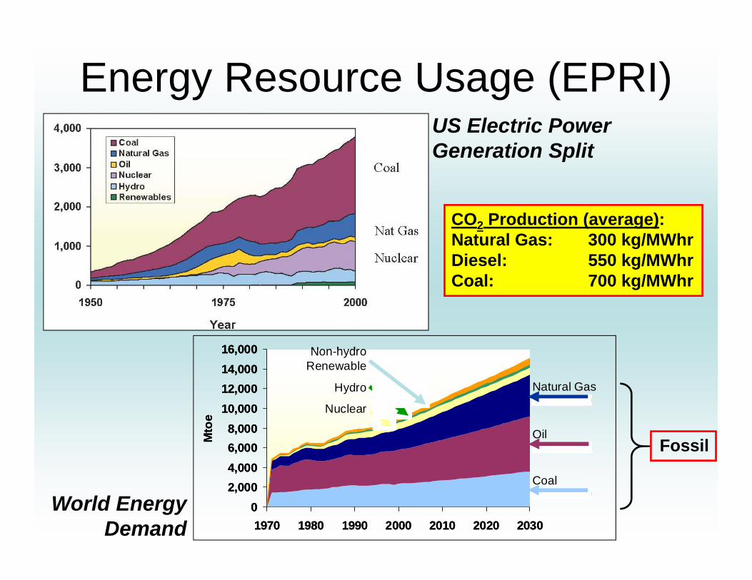
Energy Resource Usage (EPRI)
Natural Gas
Oil
Coal
02,0004,0006,0008,000
10,00012,00014,00016,000
1970 1980 1990 2000 2010 2020 2030
Mto
e
Non-hydro Renewable
Hydro
Nuclear
02,0004,0006,0008,000
10,00012,00014,00016,000
1970 1980 1990 2000 2010 2020 2030
Mto
e
Non-hydro Renewable
Hydro
Nuclear
US Electric PowerGeneration Split
World EnergyDemand
CO2 Production (average): Natural Gas: 300 kg/MWhrDiesel: 550 kg/MWhrCoal: 700 kg/MWhr
Fossil
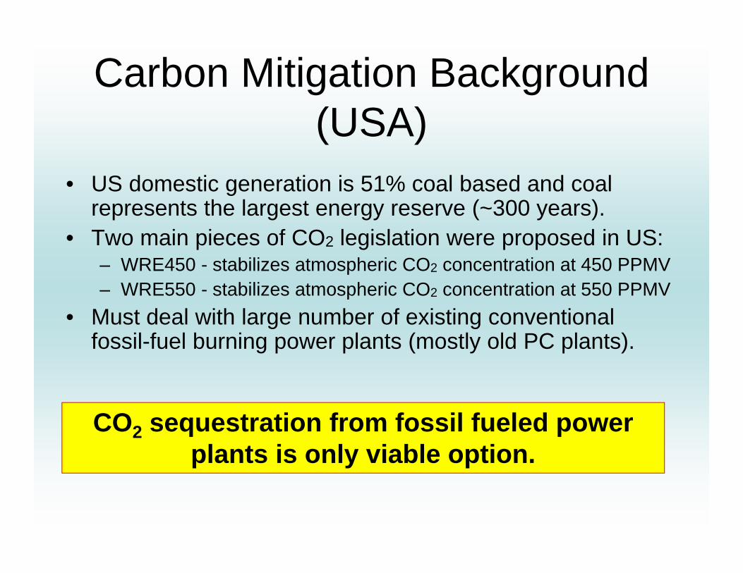
Carbon Mitigation Background (USA)
• US domestic generation is 51% coal based and coal represents the largest energy reserve (~300 years).
• Two main pieces of CO2 legislation were proposed in US:– WRE450 - stabilizes atmospheric CO2 concentration at 450 PPMV– WRE550 - stabilizes atmospheric CO2 concentration at 550 PPMV
• Must deal with large number of existing conventional fossil-fuel burning power plants (mostly old PC plants).
CO2 sequestration from fossil fueled power plants is only viable option.
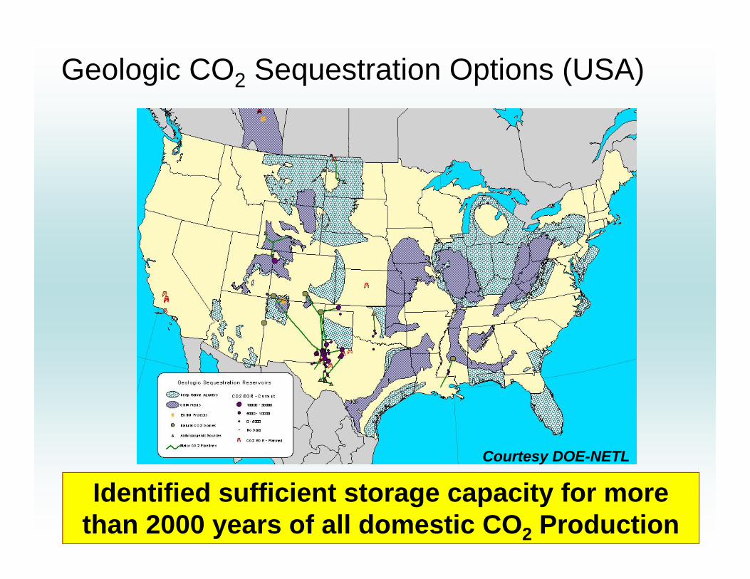
Geologic CO2 Sequestration Options (USA)
Courtesy DOE-NETL
Identified sufficient storage capacity for more than 2000 years of all domestic CO2 Production

Projected CO2 transportation capacity
Enhanced Oil Recovery Saline Formations
• 45,000 miles additional CO2 pipeline (currently about 3000 miles) with about 600 new compression stations.
• About 120 GW of new CO2 sequestration ready fossil fueled power plants.

General CO2 Technology Challenges: • Equation of state for CO2 (high pressure, high temperature, mixtures)• High compression ratios (large volume changes, long compression trains,
gear boxes, mechanical reliability)• High density (amplifies rotordynamic and impeller-dynamic forces) • Wide required operating range (function of plant load)• Strong thermodynamic path dependence (isentropic versus isothermal)• Multi-phase behavior (pumping versus compression)• Carbonic acid formation in presence of water (corrosion)• Solubility in elastomeric materials (seals, flexible ducting, packings, valves) • Liquid/ice formation when rapidly expanded (Joule-Thomson) at shaft seals
• Low sonic speed (higher shock losses and reduced operating range)
• High potential for piping acoustic resonances (dense gas)
• Selectively leeches certain elements from common metals (materials, coatings)
Future CO2 compression must consider the above challenges

Now for the technology application…
Integrated High Speed EMD Compressors:- Hermetically sealed- Process gas cooled- High speed motor direct drive- Magnetic bearings
A possible option for future CO2 compression applications???

Integrated High Speed EMD Compressor Products
SiemensSTC-ECO
MANHofim
GE ICL
GE ICL

Product Evolution:Sealed and Pressurized Casing
GE ICL Casing Integration

Product Evolution:High Speed Motors
DDS Frame 8
Size reduction

Product Evolution:Magnetic Bearings
GE ICL Bearing Placement

Product Evolution:Motor Process Gas Cooling
GE ICL

Product Evolution:High Speed Variable Frequency Drives
Converteam VFD
SiemensVFD
Super-synchronousfrequency drivers

Integrated High Speed EMD Compressors: Supplemental Equipment Avoided
A lot of mechanical equipment is not needed…
Note the smaller
footprint

Integrated High Speed EMD Compressors: Supplemental Equipment Added
…But must add a lot of electrical equipment
SubstationTransformers
VFD
Power Lines

Integrated High Speed EMD Compressors
Some advantages for users:• Compact direct drive EMD variable speed
centrifugal compressor• No gear-box• No DGS or wet seals necessary• No lubrication and cooler necessary• Deep part speed and part load possible• Compact package• “Zero” point emissions

Integrated High Speed EMD Compressors
Some disadvantages for users:• Discomfort with VFD technology and EMDs,
especially high-speed motors. Recent poor operating experience has re-enforced this view.
• Few single-source, single responsibility suppliers on market.
• Loss of control over the fuel source.• Most operators are mechanical engineers
(not EEs).

Relevant Standards on Electric MotorsAPI Std 541, “Form-Wound Squirrel Cage Induction Motors, 250 hp and Larger”
API Std 547, “General Purpose Form-Wound Squirrel Cage Induction Motors 250 hp and Larger” *Does not presently cover reciprocating compressors*
API Std 546, “Brushless Synchronous Machines, 500 kVA and Larger”
IEEE Std 519, “RP for Practices and Requirements for Harmonic Control in Electric Power Systems”
IEEE Std 841, “Severe-duty TEFC Squirrel Cage Induction Motors” * Does not presently cover reciprocating compressors*
IEEE RP 519,” RP and Requirements for Harmonic Control in Electric Power Systems”
IEEE RP 303, “RP for Auxiliary Devices for Rotating Electrical Machines in Class I, Div 2 Loc.”
NEMA MG 1-2006, “Motors and Generators”
Help! I am a Mechanical Engineer.

• Drive Train Configurations• Facility/Installation Requirements (cleanliness)• Operating Range• Options for Starting the Motor• Electrical Power Supply, Cost and Integration
Issues• Available Torque as a Function of Speed• Torque Fluctuations into the Driven Train• Electric Motor / Drive Train Efficiency • Centrifugal and Reciprocating Compressor
Application Specific Issues• Maintenance and Reliability
When considering an EMD compressor the primary technical issues to address are:
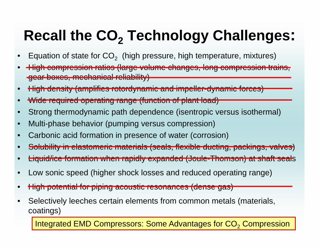
Recall the CO2 Technology Challenges: • Equation of state for CO2 (high pressure, high temperature, mixtures)• High compression ratios (large volume changes, long compression trains,
gear boxes, mechanical reliability)• High density (amplifies rotordynamic and impeller-dynamic forces) • Wide required operating range (function of plant load)• Strong thermodynamic path dependence (isentropic versus isothermal)• Multi-phase behavior (pumping versus compression)• Carbonic acid formation in presence of water (corrosion)• Solubility in elastomeric materials (seals, flexible ducting, packings, valves) • Liquid/ice formation when rapidly expanded (Joule-Thomson) at shaft seals
• Low sonic speed (higher shock losses and reduced operating range)
• High potential for piping acoustic resonances (dense gas)
• Selectively leeches certain elements from common metals (materials, coatings)
Integrated EMD Compressors: Some Advantages for CO2 Compression

Thank You Very MuchQuestions?
(Thanks to additional SwRI contributors)
Jason GatewoodSouthwest Research Institute
[email protected](210) 861-3893