Embed Size (px)
Citation preview

A product of the DOE-NARUC Natural Gas Infrastructure Modernization PartnershipAdministered by the National Association of Regulatory Utility Commissioners
Center for Partnerships & Innovation
Sampling of Methane Emissions Detection Technologies and Practices for Natural Gas Distribution Infrastructure
An Educational Handbook for State Energy Regulators

Methane Emissions Detection Handbook | 1
Lead Authors D. Ethan Kimbrel, Commissioner, Illinois Commerce CommissionJay Balasbas, Commissioner, Washington Utilities and Transportation CommissionJim Zolnierek, Bureau Chief, Bureau of Public Utilities, Illinois Commerce CommissionJoseph Fallah, Economic and Policy Advisor to Commissioner Kimbrel, Illinois Commerce CommissionCarrera Thibodeaux, Esq., Legal and Policy Advisor to Commissioner Kimbrel, Illinois Commerce Commission
Contributing EditorsDiane X. Burman, Chair, NARUC Committee on Gas and Chair, DOE-NARUC Natural Gas Infrastructure Modernization Partnership Commissioner, New York State Public Service CommissionAndreas D. Thanos, Chair, NARUC Staff Subcommittee on Gas Policy Specialist, Gas Division, Massachusetts Department of Public UtilitiesKiera Zitelman, Senior Manager, NARUC Center for Partnerships & Innovation
About the Natural Gas Infrastructure Modernization Partnership
The Natural Gas Infrastructure Modernization Partnership (NGIMP) is a cooperative effort between the U.S. Department of Energy and the National Association of Regulatory Utility Commissioners. The NGIMP con-venes state regulators, federal agencies, and other natural gas stakeholders to learn more about emerging technologies pertaining to the critically important issues around enhancing infrastructure and pipeline safety. This includes discussing natural gas pipeline leak detection and measurement tools and learning about new technologies and cost-effective practices for enhancing pipeline safety, reliability, efficiency, and deliverability. The NGIMP is chaired by Commissioner Diane X. Burman, of the New York State Public Service Commission, who also chairs the NARUC Committee on Gas.
AcknowledgmentsThis work is funded in part or whole by the U.S. Department of Energy, Fossil Energy Office, under Coopera-tive Agreement No. DE-FE0024857.
The authors wish to thank both DOE and NARUC for recognizing the need to establish the Natural Gas Infra-structure Modernization Partnership and devoting funding and staff expertise to its success.
We are also grateful to the many individuals and organizations that provided expertise, knowledge, and important technical factual information on methane emission detection technologies and practices. Specifically, we wish to thank the following individuals:
• Michael Adamo, Senior Program Manager, GTI• Gerry Bong, Engineer, GTI• Zoe Cadore, Policy Director, American Petroleum Institute• Daphne D’Zurko, Executive Director, NYSEARCH• Christopher Freitas, U.S. Department of Energy• Dennis Jarnecke, R&D Director, GTI• Dan LeFevers, Director, State & Consumer Programs, GTI• Pam Lacey, Senior Managing Counsel, American Gas Association • Eric Lounsberry, Director, Safety & Reliability Division, Illinois Commerce Commission• Sean Mayo, Director of Pipeline Safety, Washington Utilities and Transportation Commission• Bryan Pemble, Pipeline Safety Program, Illinois Commerce Commission• Timothy Reinhardt, U.S. Department of Energy• Bill Riley, Assistant Director, Safety & Reliability Division, Illinois Commerce Commission • Betsy Tansey, Distribution Systems & Engineering, American Gas Association• Kristine Wiley, R&D Director, GTI
2 | Methane Emissions Detection Handbook
We are also grateful to NARUC staff for providing outstanding assistance and expertise that significantly con-tributed to the success of this handbook, including: • Danielle Sass Byrnett, Director, NARUC Center for Partnerships & Innovation • Regina Davis, Director of Communications, NARUC
DisclaimersThis handbook was prepared as an account of work sponsored by an agency of the United States Govern-ment. Neither the United States Government nor any agency thereof, nor any of their employees, makes any warranty, express or implied, or assumes any legal liability or responsibility for the accuracy, completeness, or usefulness of any information, apparatus, product, or process disclosed, or represents that its use would not infringe privately owned rights. Reference herein to any specific commercial product, process, or service by trade name, trademark, manufacturer, or otherwise does not necessarily constitute or imply its endorsement, recommendation, or favoring by the United States Government or any agency thereof. The views and opinions of authors expressed herein do not necessarily state or reflect those of the United States Government or any agency thereof.
This handbook represents a collaborative and collective work of the individual authors and editors who con-tributed to this publication (hereinafter referred to as contributors). The information in this handbook should not be construed as potential future policies or practices of the contributors’ respective state entities or state administrations, nor interpreted as evidence that such contributors have individually or collectively made a determination with respect to the outcome of a matter or otherwise prejudiced an issue without considering all positions that may come before such contributors in other matters or proceedings. This handbook is issued exclusively as an educational handbook and is not meant to dictate a “one size fits all” regulatory approach.

Methane Emissions Detection Handbook | 3
ForewordThe Honorable Diane X. BurmanChair, DOE-NARUC Natural Gas Infrastructure Modernization PartnershipChair, NARUC Committee on GasCommissioner, New York State Public Service Commission
As Chair of the Natural Gas Infrastructure Modernization Partnership (NGIMP), it is my pleasure and privilege to submit this educational hand-book. This handbook is the product of several ongoing NGIMP collab-orations that have spanned the life of this partnership between the U.S. Department of Energy (DOE) and National Association of Regulatory Util-ity Commissioners (NARUC) since it was formed in 2016. NARUC commis-sioners have participated in numerous NGIMP activities such as technical
workshops, DOE lab tours, and other important forums and meetings focused on bringing together relevant stakeholders to educate and enhance knowledge on emerging technologies in natural gas infrastructure mod-ernization with the goal of advancing safety and reliability.
The safety, integrity, and reliability of our pipeline system is paramount. Natural gas is a critical fuel source for the U.S. economy. With regulation of natural gas shared among multiple levels of government, both federal and state officials have an interest in collaborating to seek to continuously improve the safety and efficiency of the nation’s natural gas infrastructure. To that end, this handbook was a natural work product in response to a number of emerging technologies and practices we were hearing about to detect and repair methane leaks in the distribution network. Thus, members of the NGIMP endeavored to work closely with the DOE and NARUC to produce an educational summary handbook for state public utility commissioners. This handbook shows that a variety of technologies and practices are currently in use across the natural gas industry to detect, quantify, and repair methane leaks. New tools are being developed and demonstrated with support from DOE and national labs, industry, and academia.
Thus, this handbook is designed to assist regulators by summarizing existing and emerging methane leak technologies in the context of the natural gas distribution network. It is not an exhaustive list of all the technol-ogies and practices out there, nor is it an endorsement of those that we highlight. Rather, as a work product of the NGIMP, this research is primarily meant to be used as a tool for regulators and other interested readers to understand the basics behind methane emissions technologies and practices for natural gas distribution infrastructure and facilitate a thoughtful discourse for further appropriate and responsible engagement and communication on the path forward. I want to thank Commissioner Ethan Kimbrel and Commissioner Jay Balasbas for leading this effort as well as Joseph Fallah, Sean Mayo, Carrera Thibodeaux, Jim Zolnierek, and other dedicated staff at the Illinois Commerce Commission and Washington Utilities and Transportation Com-mission, without whom we would not have been able to complete this substantive and educational handbook. They took on the arduous task of being the principal lead researchers and authors. A special thanks to Andreas Thanos and Kiera Zitelman for their review and critical assessments that helped to shape the handbook. I would also be remiss if I did not recognize the invaluable leadership support from the Committee on Gas Co-Vice Chairs -- Commissioner Julie Fedorchak, of the North Dakota PSC, and Commissioner Brandon Presley, of the Mississippi PSC. Lastly, we want to thank the countless individuals who shared their knowledge and under-standing of the technologies and issues during this process. This handbook is not the final word, especially as technologies will continue to evolve, and with that evolution comes new opportunities, new challenges, more food for thought, and likely more questions of what this future will look like. It is my hope that state commis-sioners and other interested readers will find this handbook both educational and useful.
Sincerely yours in dedicated public service, Diane X. Burman, Esq.

4 | Methane Emissions Detection Handbook
Contents
Section 1. Executive Summary . . . . . . . . . . . . . . . . . . . . . . . . . . . . . . . . . . . . . . . . . . . . . . . . . . . . . . . . . 6
Section 2. Introduction and Background . . . . . . . . . . . . . . . . . . . . . . . . . . . . . . . . . . . . . . . . . . . . . . . . 7
A. Overview of Domestic Natural Gas Production . . . . . . . . . . . . . . . . . . . . . . . . . . . . . . . . . . . . . . . . . 7
B. End Uses of Natural Gas . . . . . . . . . . . . . . . . . . . . . . . . . . . . . . . . . . . . . . . . . . . . . . . . . . . . . . . . . . . 8
C. Overview of Transmission and Distribution Infrastructure . . . . . . . . . . . . . . . . . . . . . . . . . . . . . . . . . 9
D. Stakeholders with Interest in Addressing Leaks: Interaction among Private Sector, Federal and State Regulators, and Other Groups . . . . . . . . . . . . . . . . . . . . . . . . . . . . . . . . . . . . . . 10
Section 3. Why Methane Leaks . . . . . . . . . . . . . . . . . . . . . . . . . . . . . . . . . . . . . . . . . . . . . . . . . . . . . . . . 12
A. Gas Leaks in the Transmission System are Invisible, Odorless, and Hard to Detect . . . . . . . . . . . . 12
B. Lost and Unaccounted for Gas and Cost Recovery: No Price on Escaped Gas . . . . . . . . . . . . . . . . 13
C. Millions of Miles of Distribution Pipelines: Difficulty in Access, Limited Data, and Upfront Costs to Replace Equipment Can Mean a Long Payback Period . . . . . . . . . . . . . . . . 14
D. Leaks Can Be a Threat to Human Health and the Environment . . . . . . . . . . . . . . . . . . . . . . . . . . . . 15
Section 4. Existing Technologies and Barriers to Widespread Deployment of Methane Leak Detection and Quantification Technology . . . . . . . . . . . . . . . . . . . . . . . . . . . . . . . . 18
A. Review of Existing Technologies. . . . . . . . . . . . . . . . . . . . . . . . . . . . . . . . . . . . . . . . . . . . . . . . . . . . 18
1. Flame Ionization Detector (FID) . . . . . . . . . . . . . . . . . . . . . . . . . . . . . . . . . . . . . . . . . . . . . . . . . . 18
2. Infrared Cameras. . . . . . . . . . . . . . . . . . . . . . . . . . . . . . . . . . . . . . . . . . . . . . . . . . . . . . . . . . . . . . 18
3. High-volume Dilution Sampling . . . . . . . . . . . . . . . . . . . . . . . . . . . . . . . . . . . . . . . . . . . . . . . . . . 18
4. Remote Methane Leak Detector (RMLD-IS™) . . . . . . . . . . . . . . . . . . . . . . . . . . . . . . . . . . . . . . . . 19
5. Mobile Leak Detection . . . . . . . . . . . . . . . . . . . . . . . . . . . . . . . . . . . . . . . . . . . . . . . . . . . . . . . . . 19
6. Calibrated Bag . . . . . . . . . . . . . . . . . . . . . . . . . . . . . . . . . . . . . . . . . . . . . . . . . . . . . . . . . . . . . . . 19
7. Satellite Imaging and Remote Sensing. . . . . . . . . . . . . . . . . . . . . . . . . . . . . . . . . . . . . . . . . . . . . 19
B. Barriers to Widespread Deployment of Methane Leak Detection Technologies . . . . . . . . . . . . . . . 20
Section 5. Emerging Methane Leak Detection Products and Technologies . . . . . . . . . . . . . . . . . . . 21
1. Aerial Light Detection and Ranging System (ALiDAR) from Bridger Photonics . . . . . . . . . . . . . . 21
2. Advance Leak Detection Lidar (ALDL) . . . . . . . . . . . . . . . . . . . . . . . . . . . . . . . . . . . . . . . . . . . . . 22
3. Fixed Point Laser /Open Path Laser-Sensor from Acutect . . . . . . . . . . . . . . . . . . . . . . . . . . . . . . 22
4. Gas Cloud Imaging Camera (GCI) from Rebellion Photonics. . . . . . . . . . . . . . . . . . . . . . . . . . . . 23
5. Gas Tracer from RKI. . . . . . . . . . . . . . . . . . . . . . . . . . . . . . . . . . . . . . . . . . . . . . . . . . . . . . . . . . . . 24
6. GAZOSCAN™ from GazoMat . . . . . . . . . . . . . . . . . . . . . . . . . . . . . . . . . . . . . . . . . . . . . . . . . . . . 24
7. Irwin® Portable pump-based infrared sensor from Inficon . . . . . . . . . . . . . . . . . . . . . . . . . . . . . . 25
8. Laser Methane Mini™ (LMm) from Tokyo Gas . . . . . . . . . . . . . . . . . . . . . . . . . . . . . . . . . . . . . . . . 25
9. MIRA PICO Mobile LDS from Aeris Technologies (MIRA PICO). . . . . . . . . . . . . . . . . . . . . . . . . . 26
10. MobileGuard™ from ABB / Heath Consultants Inc. . . . . . . . . . . . . . . . . . . . . . . . . . . . . . . . . . . 26

Methane Emissions Detection Handbook | 5
11. Picarro Surveyor™ (Surveyor) from Picarro Incorporated . . . . . . . . . . . . . . . . . . . . . . . . . . . . . . . 27
12. QM3000 Continuous Methane Detection System from Quanta3 . . . . . . . . . . . . . . . . . . . . . . . 28
13. RMLD-CS™ by Heath Consultants Inc. . . . . . . . . . . . . . . . . . . . . . . . . . . . . . . . . . . . . . . . . . . . . 28
14. SeekIR™ by SeekOps. . . . . . . . . . . . . . . . . . . . . . . . . . . . . . . . . . . . . . . . . . . . . . . . . . . . . . . . . . 29
Section 6. Collaborations . . . . . . . . . . . . . . . . . . . . . . . . . . . . . . . . . . . . . . . . . . . . . . . . . . . . . . . . . . . . 30
A. Methane Detectors Challenge . . . . . . . . . . . . . . . . . . . . . . . . . . . . . . . . . . . . . . . . . . . . . . . . . . . . . 30
B. Advanced Research Projects Agency-Energy . . . . . . . . . . . . . . . . . . . . . . . . . . . . . . . . . . . . . . . . . . 30
C. United States Department of Energy and National Energy Technology Lab Investments in Methane Emissions Mitigation and Quantification . . . . . . . . . . . . . . . . . . . . . . 31
D. United States Environmental Protection Agency Natural Gas STAR Methane Challenge Program . . . . . . . . . . . . . . . . . . . . . . . . . . . . . . . . . . . . . . . 31
E. Environmental Partnership . . . . . . . . . . . . . . . . . . . . . . . . . . . . . . . . . . . . . . . . . . . . . . . . . . . . . . . . 31
F. Natural Resources Defense Council . . . . . . . . . . . . . . . . . . . . . . . . . . . . . . . . . . . . . . . . . . . . . . . . . 32
G. NYSEARCH . . . . . . . . . . . . . . . . . . . . . . . . . . . . . . . . . . . . . . . . . . . . . . . . . . . . . . . . . . . . . . . . . . . . 32
H. Operations Technology Development . . . . . . . . . . . . . . . . . . . . . . . . . . . . . . . . . . . . . . . . . . . . . . . 32
I. Pipeline Research Council International . . . . . . . . . . . . . . . . . . . . . . . . . . . . . . . . . . . . . . . . . . . . . . 32
Section 7. Conclusion . . . . . . . . . . . . . . . . . . . . . . . . . . . . . . . . . . . . . . . . . . . . . . . . . . . . . . . . . . . . . . . 33
Appendix A. Select Methane Leak Detection Products and Technologies . . . . . . . . . . . . . . . . . . . . 34

6 | Methane Emissions Detection Handbook
Section 1. Executive Summary Natural gas is a critical fuel source for the U.S. economy. With regulation of natural gas shared among multiple levels of government, both federal and state officials have an interest in collaborating to seek to continuously improve the safety and efficiency of the nation’s natural gas infrastructure. To that end, the U.S. Department of Energy (DOE) and the National Association of Regulatory Utility Commissioners (NARUC) have established the Natural Gas Infrastructure Modernization Partnership (NGIMP), a technical partnership to enable investments in infrastructure modernization and repairs to natural gas distribution pipeline networks and identify new tech-nologies and cost-effective practices for enhancing pipeline safety, efficiency, and deliverability. In response to a number of emerging technologies and practices to detect and repair methane leaks in the distribution network, NGIMP members worked closely with the DOE and NARUC to produce a summary report for state public utility commissioners.
Of the 27.4 trillion cubic feet of natural gas delivered to consumers in 2018, 38.8 percent went to electric power generation, 30.2 percent to industrial customers, 18.1 percent to residential customers, 12.7 percent to commercial customers, and 0.2 percent to vehicle fuel.1 Natural gas, a mixture of hydrocarbons consisting primarily of methane, is transported from production site to end use via hundreds of thousands of miles of pipelines maintained by pipeline operators, including transmission owners and local gas distribution com-panies (LDCs). Throughout the supply chain, leaks may occur. Methane contributes to climate change as a greenhouse gas trapping heat in the atmosphere and can, in high concentrations and with other contributing circumstances, have detrimental effects on human health and the environment. Gas infrastructure leaks devel-op for a variety of reasons and can be difficult to identify and address.
Currently, a variety of technologies and practices are in use across the natural gas industry to detect, quantify, and repair methane leaks. Through the DOE and national labs, the federal government is supporting research and development of emerging tools. Industry and academia are engaging in public-private partnerships to conceptualize, develop, demonstrate, evaluate, and deploy new tools into the market, offering improved reli-ability, expanded applicability, and better cost-effectiveness.
This handbook summarizes methane leaks in the context of the natural gas distribution network. It identifies existing and emerging technologies and practices and outlines partnerships to further the development of novel tools. As a product of NGIMP, this research is primarily meant to expand state energy regulators’ un-derstanding of state-of-the-art methane leak detection tools, thereby enhancing their ability to appropriately regulate the safety and efficiency of the nation’s natural gas infrastructure. However, multiple stakeholders including federal regulators, natural gas producers and utilities, consumer and environmental advocates, and others may also benefit from increased awareness of this market and its regulatory environment.
1 U.S. Energy Information Administration, Natural Gas Consumption by End Use. Updated May 31, 2019, https://www.eia.gov/dnav/ng/ng_cons_sum_dcu_nus_a.htm.

Methane Emissions Detection Handbook | 7
Section 2. Introduction and Background
A. Overview of Domestic Natural Gas ProductionNatural gas is a naturally occurring hydrocarbon gas mixture composed primarily of methane and smaller amounts of hydrocarbons such as ethane, propane, and butane. Raw natural gas may also contain small amounts of water vapor, hydrogen sulfide, carbon dioxide, nitrogen, and helium, which are removed in gas processing to produce pipeline-quality natural gas.
Natural gas is formed when layers of decomposing organic materials in plants and animals are exposed to intense pressure and heat under the surface of the Earth over millions of years. The energy that the plants originally obtained from the sun is stored in the form of chemical bonds in the gas.
Methods used to extract natural gas depend on the location and composition of the raw gas. Natural gas wells can be drilled vertically and horizontally into natural gas formations. Hydraulically fractured horizontal wells accounted for the majority of new natural gas wells in September 2014 and have continued to multi-ply, accounting for 69 percent of all oil and natural gas wells drilled in 2016.2 Some underground natural gas reservoirs are under enough internal pressure that the gas can flow up the well and reach the surface without additional support. However, some wells require a pump to bring the gas to the surface.
Natural gas can be found in cracks and spaces between layers of rock, within the tiny pores in some formations of shale, sandstone, and other types of sedimentary rock, and within deposits of crude oil and coal. Natural gas is produced either as non-associated gas from a gas well or as associated gas from an oil well. It is then gathered from several different sources by a system of field gathering pipelines and sent to processing plants within the producing region. At these plants, liquid hydrocarbons, water, and contaminants such as sulfur dioxide and carbon dioxide are removed for sale (e.g., natural gas liquids such as propane and butane) or disposal. After processing, the natural gas is either stored or transported through a system of large-diameter transmission pipelines and then through smaller diameter distribution pipelines to regional markets where it is either stored or consumed directly by end users. Hydraulic fracturing is a production process that forces water, chemicals, and sand down a well under high pressure to release and extract natural gas from shale and other types of sedimentary rock formations.
Chart 2.1 shows U.S. Natural Gas Marketed Production over time. Notable in Chart 2.1 is the steep increase in production beginning in the mid to late 2000s. In the 1970s and 1980s, conventional sources of economically extractable natural gas were considered to be largely exhausted. In the mid to late 2000s, advances in horizon-tal drilling, hydraulic fracturing, and other well stimulation technologies made trillions of cubic feet of shale gas
2 U.S. Energy Information Administration, Today in Energy: Hydraulically Fractured Horizontal Wells Account for Most New Oil and Natural Gas Wells. Released January 30, 2018, https://www.eia.gov/todayinenergy/detail.php?id=34732.
Source: U.S. Energy Information Administration, February 28, 2019.

8 | Methane Emissions Detection Handbook
both technically recoverable and economical to produce. The United States became a net natural gas exporter on an annual basis in 2017.3 The U.S. Energy Information Administration predicts that natural gas production will continue to increase into the foreseeable future.4
As shown in Chart 2.2, Texas, Pennsylvania, and Oklahoma, each of which produce large amounts of natural gas from shale deposits, lead the U.S. in domestic natural gas production.
Chemically identical to conventional natural gas, renewable natural gas (RNG) is a pipeline-quality gas that is fully interchangeable with conventional natural gas and has a methane concentration of 90 percent or greater. Biogas is a gaseous form of methane obtained from biomass. It can be produced from decaying materials including organic wastes and manure as well as from the gasification of wood wastes. Biomethane results from the collection and cleaning of the biogas of decaying organic wastes and manures.
B. End Uses of Natural GasNatural gas has a wide variety of uses in homes, businesses, and factories. It is used as a cooking and heating fuel in households to power furnaces, water heaters, stoves, ovens, fireplaces, clothes dryers, and other appliances. In commercial build-ings, natural gas is primarily used for space and water heating. In many manufacturing processes, natural gas is used as a heat source to melt, dry, bake, or glaze a product. In factories, it is used in making glass, steel, cement, bricks, ceramics, tile, paper, food products and many other commodi-ties. Additionally, natural gas is used as a feedstock to make fertilizer, antifreeze, plastics, pharmaceu-ticals and fabrics, and a wide range of chemicals such as ammonia, methanol, butane, ethane, pro-pane, and acetic acid. Natural gas is used at many industrial facilities for incineration as well.
Natural gas is also used in the transportation sec-tor. For example, it is used to fuel vehicles, mostly in heavy duty applications, and in rail and marine shipping.
3 U.S. Energy Information Administration, Annual Energy Outlook 2019. January 24, 2019, at 14, https://www.eia.gov/outlooks/aeo/.
4 Id. at 72.
Source: U.S. Energy Information Administration, February 28, 2019.
Source: U.S. Energy Information Administration, February 28, 2019.

Methane Emissions Detection Handbook | 9
Increasingly in recent years, natural gas has been used to generate electric power. Natural gas power plants often generate electricity in gas turbines, directly using the hot exhaust gases of fuel combustion. Natural gas turbines can ramp up quickly, making them an essential back-up for solar and wind generation. Of the three fossil fuels used for power generation (coal, oil, and natural gas), natural gas emits the least carbon dioxide per unit of energy produced. Given its affordability (natural gas prices have been consistently low by historic standards) and consumers’ concerns regarding carbon dioxide emissions and air quality, the use of natural gas for electricity generation has increased and is projected to continue growing.
Chart 2.3 shows the shares of natural gas consumed in the U.S. by different end user classes.
C. Overview of Transmission and Distribution InfrastructureThe transportation system for natural gas consists of a complex network of pipelines designed to quickly and efficiently transport natural gas from the wells where it is produced to areas of demand. There are three major types of natural gas pipelines: the gathering system, the interstate/intrastate transmission pipeline and stor-age system, and the distribution system. Production comes from just under 500,000 active gas wells5 utilizing 18,000 miles of gathering lines.6 As of the end of 2017, 510 natural gas processing plants were active in the lower 48 states to extract natural gas liquids, remove impurities, and compress gas to transmission line pres-sure7 for delivery into 300,000 miles of transmission lines.8 Approximately 400 natural gas storage facilities ca-pable of storing more than 4 trillion cubic feet of gas exist throughout the U.S. to mitigate seasonal fluctuations in supply and demand.9 Finally, gas is distributed to customers through 1.3 million miles of distribution lines10 to 62.1 million residential customers, 5.5 million commercial customers, and 200,000 industrial customers.11
The gathering system consists of pipelines that transport raw natural gas from the wells to the processing plant or, in the case of dry gas that is already pipeline-quality, directly to a transmission line. In processing, impurities and various non-methane hydrocarbons such as ethane, propane, butane, hydrogen sulfide, and helium may be par-tially or completely removed to be processed and sold as separate commodities. Other components, such as wa-ter vapor, carbon dioxide, and nitrogen, are removed to meet interstate/intrastate pipeline quality specifications.
The interstate/intrastate transmission pipeline system transports pipeline-quality natural gas from processing plants in producing regions to those areas with high natural gas requirements. The pipeline network extends across the entire country. Natural gas that is transported through interstate/intrastate transmission pipelines travels at high pressure, which reduces the volume of the natural gas being transported and propels the nat-ural gas through the pipeline. Compression of natural gas is accomplished by compressor stations placed at various intervals along the pipeline. The natural gas enters the compressor station, where it is compressed by either a turbine, motor, or engine. Metering stations are placed periodically along the pipelines to measure the flow of gas along the pipeline. Valves along the pipelines can be closed when flows must be stopped for emergencies or for replacing or maintaining pipelines. Finally, to monitor and control the natural gas that is traveling through the pipeline, centralized gas control stations collect, assimilate, and manage data received from monitoring and compressor stations all along the pipe. These systems use flow rates through the pipe-line, operational status, pressure, and temperature readings to assess the status of the pipeline.
5 U.S. Energy Information Administration, Number of Producing Gas Wells. Updated May 31, 2019, https://www.eia.gov/dnav/ng/ng_prod_wells_s1_a.htm.
6 Bureau of Transportation Statistics, U.S. Oil and Gas Pipeline Mileage. Updated March 28, 2019, https://www.bts.gov/content/us-oil-and-gas-pipeline-mileage.
7 U.S. Energy Information Administration, Today in Energy: U.S. Natural Gas Processing Plant Capacity and Throughput Have Increased in Recent Years. Released March 7, 2019, https://www.eia.gov/todayinenergy/detail.php?id=38592.
8 Bureau of Transportation Statistics, U.S. Oil and Gas Pipeline Mileage. Updated March 28, 2019, https://www.bts.gov/content/us-oil-and-gas-pipeline-mileage.
9 U.S. Energy Information Administration, Underground Natural Gas Working Storage Capacity. Updated March 29, 2019, https://www.eia.gov/naturalgas/storagecapacity/.
10 Bureau of Transportation Statistics, U.S. Oil and Gas Pipeline Mileage. Updated March 28, 2019, https://www.bts.gov/content/us-oil-and-gas-pipeline-mileage.
11 U.S. Energy Information Administration, Number of Natural Gas Consumers. Updated May 31, 2019, https://www.eia.gov/dnav/ng/ng_cons_num_dcu_nus_a.htm.

10 | Methane Emissions Detection Handbook
Distribution systems transport natural gas from delivery points located on interstate and intrastate pipelines to households and businesses. The delivery point where the pipeline-quality natural gas is transferred from a transmission pipeline (or a local producer) to a natural gas distribution company is often colloquially called the “city gate.”12 The natural gas to be distributed is typically depressurized at or near the city gate, as well as scrubbed and filtered to ensure low moisture and particulate content. Typically, local distribution companies take ownership of the natural gas at the city gate and deliver it to each individual customer’s meter. Distri-bution systems are similar to interstate/intrastate transportation systems but move smaller volumes of gas at much lower pressures over shorter distances to a great number of individual users. Supervisory control and data acquisition (SCADA) systems, similar to those used by large pipeline companies, are also used by local distribution companies. These systems can integrate gas flow control and measurement with other account-ing, billing, and contract systems to provide a comprehensive measurement and control system for the local gas utility.
Natural gas can be stored for an indefinite period, so storage is used in conjunction with the natural gas trans-portation system as well. Storage has traditionally allowed excess supply delivered during the summer months to meet increased demand during winter months, although recent increases in natural gas fired generation have mitigated demand fluctuations between the summer and winter months. Stored natural gas is also used to meet demand during unforeseen accidents, major storms, natural disasters, or other occurrences that may affect the production or delivery of natural gas. At the end of 2017, there was 9,260,590 million cubic feet of underground natural gas storage capacity in the U.S., including salt caverns, aquifers, and depleted fields.13
D. Stakeholders with Interest in Addressing Leaks: Interaction among Private Sector, Federal and State Regulators, and Other GroupsThere are numerous ownership models for natural gas pipelines. Interstate transmission pipelines can be owned by private or publicly traded companies. Natural gas distribution pipelines are owned by public utili-ties, which in turn can be privately held or publicly traded, cooperatives, or municipal utilities. All such entities are subject to pipeline safety regulation by federal or state authorities.
Interstate pipelines are managed by the Federal Energy Regulatory Commission (FERC) and the U.S. De-partment of Transportation (DOT). FERC regulates pipelines, storage, natural gas transportation in interstate commerce, and liquefied natural gas facility construction. It also oversees operation of pipeline facilities at U.S. points of entry for natural gas imports and exports and analyzes environmental impacts of natural gas projects.
Pursuant to Federal Statutes, the United States Department of Transportation, Pipeline and Hazardous Mate-rials Safety Administration (PHMSA) has authority to ensure the safety of the U.S. natural gas transportation system. The mission of PHMSA is:
… To protect people and the environment by advancing the safe transportation of energy and other hazardous materials that are essential to our daily lives. To do this, the agency establishes national policy, sets and enforces standards, educates, and conducts research to prevent incidents. We also prepare the public and first responders to reduce consequences if an incident does occur.14
Whereas PHMSA is largely responsible for developing nationally applicable pipeline safety regulations and conducting inspections on interstate pipelines, individual states’ certified pipeline safety agencies govern intrastate pipelines. When intrastate pipelines are regulated by these agencies through adoption and enforce-
12 For convenience, this document uses the term “city gate.” However, note that some companies also use the term “city gate” to refer to pressure reduction stations within the distribution system, which can lead to confusion. For this reason, the U.S. Environmental Protection Agency (U.S. EPA) has defined this delivery point more precisely to be the local distribution company’s “LDC custody transfer station.” “Local distribution company (LDC) custody transfer station means a metering station where the LDC receives a natural gas supply from an upstream supplier, which may be an interstate transmission pipeline or a local natural gas producer, for delivery to customers through the LDC’s intrastate transmission or distribution lines.” 40 C.F.R. Part 60, Subpart OOOOa, §60.5430a (New Source Performance Standards for Crude Oil and Natural Gas Facilities).
13 U.S. Energy Information Administration, Underground Natural Gas Working Storage Capacity. Updated February 28, 2019, https://www.eia.gov/naturalgas/storagecapacity/.
14 Pipeline and Hazardous Materials Safety Administration, PHMSA’s Mission. https://www.phmsa.dot.gov/about-phmsa/phmsas-mission.

Methane Emissions Detection Handbook | 11
ment of PHMSA safety standards, PHMSA’s role is to oversee state agency performance. The state maintains direct regulatory authority to ensure natural gas pipelines are operated in compliance with federal and state statutes, rules, and regulations.
Oversight of natural gas pipelines pertains to the design, construction, operation and maintenance of the facil-ities. Incidents involving natural gas facilities resulting in injury requiring hospitalization, a fatality, or property damage are investigated. Traditionally, the primary concern of PHMSA and its state agency partners has been with preventing pipeline failures that can kill and injure people, damage property, harm the environment, and disrupt energy supplies.
In 2011, the low-pressure distribution line explosions in San Bruno, California, and Allentown, Pennsylvania, resulted in multiple fatalities and millions of dollars of property damage. In response, in April of 2011, Trans-portation Secretary Ray LaHood and PHMSA issued a Call to Action to engage all the state pipeline regulatory agencies, technical and subject matter experts, and pipeline operators to accelerate the repair, rehabilitation, and replacement of the highest-risk pipeline infrastructure.15
Increasingly, attention has also been focused on the greenhouse effects of natural gas leaks. On October 23, 2015, in the San Fernando Valley in California, at the Aliso Canyon underground storage facility, one of its nat-ural gas wells blew out, leading to a large release of methane. Unfortunately, the leak was not fully contained until February 11, 2016. An estimated 97,100 metric tons of methane was released into the atmosphere as a result. Following this incident, PHMSA revised the federal pipeline safety regulations to address critical safety issues related to downhole facilities at underground natural gas storage facilities.16
In addition to government regulators, there are numerous stakeholders with interest in addressing issues relat-ed to natural gas leaks. For instance, the oil and natural gas industries have taken tremendous strides to prevent leakage within the gathering lines and the interstate/intrastate pipeline system. In 2018, oil and natural gas producers launched the Environmental Partnership with the mission of reducing methane emissions.17 In addi-tion, the Gas Technology Institute (GTI), with support from the natural gas industry, is a research, development, and training organization serving the global natural gas industry and energy market. GTI’s Center for Methane Research was formed specifically to “provide a centralized industry-wide technical and policy support resource focused on the presence, measurement, and potential impacts of methane in the atmosphere.”18 The Illinois Citizens Utility Board (CUB) is another example. CUB, a nonprofit and nonpartisan organization, with a mission to represent the interests of residential utility customers across Illinois, worked with the Peoples Gas Light and Coke Company to develop a program providing for advanced leak detection technologies and leak quantifi-cation methods on a pilot basis.19 Environmental groups also, as more fully explained later, have been active in advocating for technologies and processes that reduce the release of natural gas into the environment.
15 See, Pipeline and Hazardous Materials Safety Administration, Pipeline Replacement Updates: Call to Action. https://opsweb.phmsa.dot.gov/pipeline_replacement/action.asp.
16 See, Pipeline and Hazardous Materials Safety Administration, Underground Natural Gas Storage. Updated May 31, 2019, https://www.phmsa.dot.gov/pipeline/underground-natural-gas-storage/underground-natural-gas-storage.
17 The Environmental Partnership. https://theenvironmentalpartnership.org/.
18 See Gas Technology Institute, GTI Project Number 22081, An Introduction to Methane and the Center for Methane Research. June 7, 2018, http://www.gti.energy/wp-content/uploads/2018/09/Intro-to-Methane-and-Center-for-Methane-Research_June-2018.pdf.
19 Illinois Commerce Commission, Docket No. 16-0376, Joint Cross Exhibit on Behalf of the Citizens Utility Board and The Peoples Gas Light and Coke Company. September 12, 2017, https://www.icc.illinois.gov/docket/files.aspx?no=16-0376&docId=256611.

12 | Methane Emissions Detection Handbook
Section 3. Why Methane Leaks
A. Gas Leaks in the Transmission System are Invisible, Odorless, and Hard to DetectNatural gas is odorless, colorless, and tasteless, making it difficult to detect. Today, mercaptan, a chemical containing and smelling of sulfur, is added to natural gas in distribution systems and other facilities near population centers. This pungent-smelling gas gives off an odor recognizable to natural gas consumers, which makes natural gas easier to detect. Despite the addition of mercaptan, however, methane leaks can be difficult to detect in some situations. In interstate pipelines or other facilities where mercaptan has not yet been injected, other detection methods are used.
In 2016, methane emissions totaled approximately 419 billion cubic feet of gas, the equivalent of 202 mil-lion metric tons of carbon dioxide. Sixteen percent (approximately 32 million metric tons of carbon dioxide equivalent) was associated with transmission and storage emissions and 6 percent with distribution system
emissions.20 Chart 3.1 shows methane emissions by segment from oil and gas infrastructure.
Methane emissions within the natural gas transpor-tation system can occur for several reasons. Natu-ral gas can leak from devices, by design, that con-trol gas flows, levels, temperatures, and pressures in the equipment. Methane can also vent, as a safety measure, by design from pneumatic controllers and storage tanks. Leaks can occur as well because of corrosion, cracking and because of manufacturing or construction defects. Natural gas can furthermore leak when pipes or equipment are broken or dam-aged by construction or digging or by earthquakes or other natural forces.
Identifying and quantifying methane leaks in natural gas transmission and distribution systems is inherent-ly difficult. Equipment leaks are often not systematic and, therefore, difficult to predict. Moreover, it can be difficult to access sites where leaks are occurring when, for example, a site is not safe to access. Addi-
20 U.S. Environmental Protection Agency, Estimates of Methane Emissions by Sector in the United States. https://www.epa.gov/natural-gas-star-program/estimates-methane-emissions-sector-united-states.
Source: United States Environmental Protection Agency, Inventory of U.S. Greenhouse Gas Emissions and Sinks: 1990–2017
Source: United States Environmental Protection Agency, Inventory of U.S. Greenhouse Gas Emissions and Sinks: 1990–2017

Methane Emissions Detection Handbook | 13
tionally, weather and other meteorological conditions can prevent proper functioning of leak detection equip-ment in some situations.21
Leaks from production and transportation are not the sole sources of methane emissions. Methane is emitted into the atmosphere by both natural and anthropogenic sources. Methane is emitted naturally by methane producing microbes in oceans, wetlands, and through the digestive processes of termites. It is also emitted by municipal sewage or through biomass burning such as wildfires. Further, methane is a byproduct of numer-ous agricultural processes. For example, methane is produced and emitted by livestock through their normal digestive process and by microbes in rice paddies. Lastly, methane is also produced through burning fossil fuels. Studies typically distinguish biogenic from thermogenic sources by evaluating methane to ethane ratios, because unlike thermogenic fossil sources, biogenic sources of methane do not also emit ethane. Advanced methane emissions leak detection tools can differentiate emissions from anthropogenic, thermogenic, and biogenic sources through carbon isotope signatures. Chart 3.2 shows methane emissions by sector.
B. Lost and Unaccounted for Gas and Cost Recovery: No Price on Escaped GasEach step of the natural gas delivery system contains the potential to create lost and unaccounted for natural gas (LAUF), which is created when measured physical inputs into a natural gas system, such as an interstate pipeline, exceed measured physical outputs. With respect to the distribution system, natural gas is typically measured at the city gate when it is transferred from an interstate or intrastate pipeline to a local distribution company. In such cases, the difference between the measurement at the city gate and gas sold to customers as reported on their bills is often considered LAUF.
A comprehensive LAUF study prepared in December 2014 by ICF International for the Massachusetts De-partment of Public Utilities (Massachusetts DPU) importantly “distinguishes three concepts that are routinely confused: (1) LAUF, (2) lost gas, and (3) methane emissions.” The ICF study explains:
• “LAUF” refers to the difference between the total amount of gas that a gas distribution company purchas-es and the amount it delivers to customers. It includes all components of loss, such as leakage, venting, theft, and gas used by the distribution company itself, adjusted by some companies for meter errors, bill-ing cycle issues, and other considerations. LAUF is essentially an accounting concept.
• “Lost gas” refers to all natural gas that escapes from the distribution system. For example, all vented gas is lost to the distribution system, but stolen gas does not escape from the distribution system and does not count as “lost.” Lost gas is a subset of LAUF.
• “Methane emissions” refers to the methane portion of natural gas that actually reaches the atmosphere. It is important to understand that not all LAUF or even lost gas results in methane emissions. For example, some leaking gas never reaches the atmosphere, and thus does not end up as “methane emissions” (al-though it is “lost”). Methane emissions are a subset of lost gas (and therefore also of LAUF).22
LAUF includes metering accounting differences, gas theft, and gas used by the utility or pipeline. Emissions are a relatively minor component. Metering accounting is the main driver of LAUF, and is due to the difference between the large, sophisticated meters at city gates—that continuously measure pressure, temperature and throughput—and the smaller, simpler, and more affordable meters at homes and businesses that are read only once per month in widely differing temperatures. The resulting differences in meter accounting are so funda-mental to LAUF that it is not uncommon to have negative LAUF numbers in some months.
At the distribution system level, LAUF is often addressed in utility ratemaking processes. Local distribution companies recover the costs of LAUF by passing such costs through to ratepayers. These costs may be re-covered through base rates, through adjusted natural gas supply prices, or through explicit LAUF charges. To account for lost and unaccounted for gas, pipelines may increase transportation charges to shippers of natural
21 Omara, Mark et al., Methane Emissions from Natural Gas Production Sites in the United States: Data Synthesis and National Estimate, Environ. Sci. Technol. 2018, 52, 12915-12925, https://pubs.acs.org/doi/10.1021/acs.est.8b03535.
22 ICF International, prepared for Massachusetts DPU, Lost and Unaccounted for Gas. December 23, 2014, at ii, https://www.mass.gov/files/documents/2016/08/vt/icf-lauf-report.pdf.

14 | Methane Emissions Detection Handbook
gas or may require customers to purchase additional supplies so that such additional supplies plus delivered supplies equal the amount of natural gas initially sent to the customers. Natural gas producers, pipeline busi-nesses, and local distribution companies will find it more difficult to profitably compete in natural gas markets when companies cannot recover the costs of lost and unaccounted for natural gas.
Of note, lost and unaccounted for gas cannot be used to measure or estimate natural gas emissions, because LAUF may result mainly from differences in the technical capability of meters and variations in temperature and pressure rather than system leaks. In addition, some discrepancies can result from human error (e.g., in-correctly inputting measurement information) or meter inaccuracies. Similarly, when natural gas volumes are estimated from samples, estimates may differ from actual volumes. Theft of natural gas or meter tampering can also contribute to lost and unaccounted for natural gas.
C. Millions of Miles of Distribution Pipelines: Difficulty in Access, Limited Data, and Upfront Costs to Replace Equipment Can Mean a Long Payback PeriodIn 2017, there were about 3 million miles of U.S. natural gas transmission and distribution pipelines that de-livered approximately 25 trillion cubic feet of natural gas to 75 million customers.23 Installing leak monitoring equipment over such an extensive and vast network is neither simple nor free of cost. In urban and industrial environments, pipes may be beneath buildings or other infrastructure, located in ceilings, behind walls and bulkheads, or in otherwise inaccessible locations such as locked buildings. In rural locations, pipelines can be buried, underwater, or otherwise inaccessible to vehicles. Even if the pipelines were easily accessible though, the cost of installing leak detection technology within or around 3 million miles of pipeline would be imprudent.
A recent study24 by Enbridge, a multinational energy transportation company, exemplifies the potential diffi-culties involved with installing leak detection systems on hard-to-reach liquid fuels pipelines.25 LDCs responsi-ble for gas distribution pipelines face different challenges and responsibilities, and. Gas distribution pipeline operators are required under the Pipeline Integrity, Protection, Enforcement, and Safety (PIPES) Act of 2006 to develop distribution pipeline integrity management programs (DIMPs) in compliance with PHMSA standards. DIMPs must outline how LDCs plan to identify threats, rank and evaluate risks, address risks through an effec-tive leak management program, and measure performance.26, 27
Physical differences between liquids and gas pipelines result in unique challenges for detecting leaks in liquid systems.28 For example, while large breaks in liquid lines may quickly cause changes in rates of flow and be quickly identified, natural gas pipeline leaks may change pipeline pressures more slowly and take longer to
23 U.S. Energy Information Administration, Natural Gas Explained: Natural Gas Pipelines. Updated December 19, 2018, https://www.eia.gov/energyexplained/index.php?page=natural_gas_pipelines.
24 Enbridge, Report on Feasibility of Installing an Alternative Leak Detection System at the Straits of Mackinac, United States v. Enbridge Energy et al Case 1:16 – cv-914. November 19, 2017, https://www.epa.gov/sites/production/files/2018-11/documents/enbridge_report_on_feasibility_of_installing_an_alternative_leak_detection_system_at_the_straits_of_mackinac.pdf.
25 Enbridge examined the feasibility of installing several different alternative leak detection systems on an underwater light crude and natural gas liquids pipeline at the Straits of Mackinac taking into account: “(i) the potential effectiveness of the technology in detecting leaks and ruptures of different sizes, (ii) the practicability of deploying the technology in the Straits of Mackinac, (iii) the practicability of long-term operation and maintenance of the technology, and (iv) the net present cost of the technology, taking into account the initial capital cost to install the technology and the annual expense to operate and maintain the technology.” Notably, all of the technologies considered involved significant initial capital installation costs as well as ongoing operating and maintenance costs. Enbridge also found several of the leak detection technologies to be either of low effectiveness, difficult to deploy, or difficult to maintain. More recently, Enbridge examined additional technologies finding none of the examined technologies to be “currently practicable for deployment at the Straits.”
26 U.S. Department of Energy, Natural Gas Infrastructure Modernization Programs at Local Distribution Companies: Key Issues and Considerations. January 2017, https://www.energy.gov/sites/prod/files/2017/01/f34/Natural%20Gas%20Infrastructure%20Modernization%20Programs%20at%20Local%20Distribution%20Companies--Key%20Issues%20and%20Considerations.pdf.
27 As of publication, Congress is considering a proposal to reauthorize the U.S. Department of Transportation’s pipeline safety programs for fiscal years 2020 through 2023. See Pipeline and Hazardous Materials Safety Administration, U.S. Transportation Secretary Elaine L. Chao Announces 2019 Pipeline Safety Legislative Proposal. June 3, 2017, https://www.phmsa.dot.gov/news/pipeline-safety-reauthorization.
28 Shaw, David et al., Pipeline and Hazardous Materials Safety Administration, Final Report: Leak Detection Study DTPH56-11-D-000001. December 10, 2012, at 2-13, https://www.phmsa.dot.gov/sites/phmsa.dot.gov/files/docs/technical-resources/pipeline/16691/leak-detection-study.pdf.
Methane Emissions Detection Handbook | 15
identify. Similarly, natural gas leaks will also dissipate in the atmosphere and not be as readily noticeable as a liquid leak that will puddle or flow above or below ground. Natural gas pipelines may require additional re-sources to detect leaks due to their larger footprint compared to liquid pipelines: in 2017, the U.S. Bureau of Transportation Statistics recorded 1.6 million miles of gas pipelines and 215,000 miles of oil pipelines.29
Needless to say, the risks inherent in the adoption of new technology must be considered when estimating the costs of installing new advanced leak detection technologies. Deploying, operating, and maintaining a new technology often requires additional unforeseen costs and delays for items such as research and development, training contractors unfamiliar with pipeline operations, and repeating deployment or maintenance work to address issues with the technology. However, new technologies can offer increased benefits compared to ex-isting technology including improved accuracy and precision, broader applicability, and other characteristics. In some cases, these benefits can justify the upfront cost barriers to new technology adoption. Cost and per-formance data for new technologies are needed for regulators to conduct cost-benefit analysis.
D. Leaks Can Be a Threat to Human Health and the EnvironmentIn a recent incident report, the National Transportation Safety Board stated:
On September 13, 2018, a series of explosions and fires occurred after high-pressure natural gas was released into a low-pressure gas distribution system in the northeast region of the Merrimack Valley in Massachusetts. The system over-pressure damaged 131 structures, including at least 5 homes that were destroyed in the city of Lawrence and in the towns of Andover and North Andover. Most of the damage was a result of structure fires ignited by gas-fueled appliances. Several structures were destroyed by natural gas explosions. One person was killed and at least 21 individuals, including 2 firefighters, were transported to the hospital. Seven other firefighters received minor injuries.30
As incidents such as this in the Merrimack Valley reveal, within specific concentration levels, natural gas has the potential to explode if an ignition source is introduced.
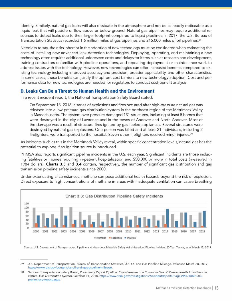
PHMSA also reports significant pipeline incidents in the U.S. each year. Significant incidents are those includ-ing fatalities or injuries requiring in-patient hospitalization and $50,000 or more in total costs (measured in 1984 dollars). Charts 3.3 and 3.4 contain, respectively, the number of significant gas distribution and gas transmission pipeline safety incidents since 2000.
Under extenuating circumstances, methane can pose additional health hazards beyond the risk of explosion. Direct exposure to high concentrations of methane in areas with inadequate ventilation can cause breathing
29 U.S. Department of Transportation, Bureau of Transportation Statistics, U.S. Oil and Gas Pipeline Mileage. Released March 28, 2019, https://www.bts.gov/content/us-oil-and-gas-pipeline-mileage.
30 National Transportation Safety Board, Preliminary Report Pipeline: Over-Pressure of a Columbia Gas of Massachusetts Low-Pressure Natural Gas Distribution System. October 11, 2018, https://www.ntsb.gov/investigations/AccidentReports/Pages/PLD18MR003-preliminary-report.aspx.
Source: U.S. Department of Transportation, Pipeline and Hazardous Materials Safety Administration, Pipeline Incident 20-Year Trends, as of March 12, 2019.

16 | Methane Emissions Detection Handbook
difficulties, suffocation, dehydration, nausea, vomiting, dizziness, confusion, blurred vision and increased heart rate.31 High exposure to ethyl mercaptan, an added odorant to naturally odorless natural gas, can cause nau-sea, fatigue, and olfactory and mucosal irritation.32
The natural gas process also produces secondary sources of emissions associated with combustion of fossil fuels to power natural gas equipment, machinery, and transportation.33 Nevertheless, natural gas is considered cleaner burning than other fossil fuels because burning natural gas not emit mercury or sulfur dioxide, and it produces less carbon dioxide, nitrogen oxide and other particulates than burning coal or petroleum oil. Nat-ural gas has been considered by some as a bridge fuel to future reliance on cleaner renewable and emission free energy.
Methane is considered a greenhouse gas that traps heat in the atmosphere, and its emissions are associated with contributing to the overall climate and health effects of greenhouse gas emissions. The U.S. Environmen-tal Protection Agency has published an Endangerment Finding identifying the following impacts of green-house gas emissions:
• Temperature. There is evidence that the number of extremely hot days is already increasing. Severe heat waves are projected to intensify, which can increase heat-related mortality and sickness. Fewer deaths from exposure to extreme cold is a possible benefit of moderate temperature increases. Recent evidence suggests, however, that the net impact on mortality is more likely to be a danger because heat is already the leading cause of weather-related deaths in the United States.
• Air Quality. Climate change is expected to worsen regional ground-level ozone pollution. Exposure to ground level ozone has been linked to respiratory health problems ranging from decreased lung function and aggravated asthma to increased emergency department visits, hospital admissions, and even prema-ture death. The impact on particulate matter remains less certain.
• Climate-Sensitive Diseases and Aeroallergens. Potential ranges of certain diseases affected by tem-perature and precipitation changes, including tick-borne diseases and food and water-borne pathogens, are expected to increase. Climate change could also impact the production, distribution, dispersion, and allergenicity of aeroallergens and the growth and distribution of weeds, grasses, and trees that produce them. These changes in aeroallergens and subsequent human exposures could affect the prevalence and severity of allergy symptoms.
31 National Institutes of Health, U.S. National Library of Medicine, Methane. https://toxtown.nlm.nih.gov/chemicals-and-contaminants/methane.
32 National Institutes of Health, National Center for Biotechnology Information, Ethyl Mercaptan Acute Exposure Guideline Levels. 2013, https://www.ncbi.nlm.nih.gov/books/NBK201325/.
33 See, Lattanzio, Richard, Congressional Research Service, Methane and Other Air Pollution Issues in Natural Gas Systems. Updated November 5, 2018, https://fas.org/sgp/crs/misc/R42986.pdf.
Source: U.S. Department of Transportation, Pipeline and Hazardous Materials Safety Administration, Pipeline Incident 20-Year Trends, as of March 12, 2019.

Methane Emissions Detection Handbook | 17
• Vulnerable Populations and Environmental Justice. Certain parts of the population may be especially vulnerable to climate impacts, including the poor, the elderly, those already in poor health, the disabled, those living alone, and/or indigenous populations dependent on one or a few resources. Environmental justice issues are clearly raised through examples such as warmer temperatures in urban areas having a more direct impact on those without air-conditioning.
• Extreme Events. Storm impacts are likely to be more severe, especially along the Gulf and Atlantic coasts. Heavy rainfall events are expected to increase, increasing the risk of flooding, greater runoff and erosion, and thus the potential for adverse water quality effects. These projected trends can increase the number of people at risk from suffering disease and injury due to floods, storms, droughts, and fires.34
34 U.S. Environmental Protection Agency, Greenhouse Gas Endangerment Finding: Health Effects. https://www.epa.gov/ghgemissions/greenhouse-gas-endangerment-finding-health-effects.

18 | Methane Emissions Detection Handbook
Section 4. Existing Technologies and Barriers to Widespread Deployment of Methane Leak Detection and Quantification Technology
A. Review of Existing TechnologiesLDCs providing natural gas to businesses and residential users have traditionally employed a routine leak detec-tion survey with a “sniffer” device, such as a flame ionization detector that identifies methane concentrations in air. In the last several years, methane detection and quantification technologies have rapidly improved beyond this traditional “walk and sniffer” device. This section will briefly describe some of the most common methane leak detection technologies in use today. While all of these devices are generally commercially available, these tech-nologies come at an increased cost and also have varying degrees of availability, effectiveness, and applicability.
1. Flame Ionization Detector (FID)The most common leak detection device in the industry, flame ioniza-tion, is a sensor technology that quantifies gas concentrations through a method of passing the sample air through a combustion chamber where the sample air is burned at a high temperature in a clear hydrogen flame. Volatile Organic Compound (VOC) and hydrocarbon molecules are charged through the burning process to become ions. The positive charged ions are then collected onto an electrode. The amount of pos-itive charge on the electrode is then proportional to the gas concentra-tion. The device’s effectiveness is limited by humidity, temperature and other contaminants in the area. The FID, however, is neither suitable for the detection of carbon monoxide nor inorganic concentrations.35
2. Infrared CamerasInfrared camera devices, such as the FLIR GF320, use op-tical imaging to screen inaccessible locations or remote facilities. The cameras display hydrocarbon emissions in a moving image using the infrared properties of the VOC and hydrocarbons. This technology allows for fast and safe de-tection, but its effectiveness is often influenced by weather conditions and can sometimes have difficulty identifying low concentrations of methane.
3. High-Volume Dilution SamplingUsed after an identified leak, the high-volume dilution sampling approach measures an individual emission rate (such as a leak at a single component) by drawing in the source’s total emissions with a large air flow and assumes to capture the entire leak. The device quantifies the volume of methane emitting from the leak. High-volume samplers are equipped with dual hydrocarbon detectors. The only commercially of-fered high volume model is the Bacharach Hi-Flow SamplerTM, a portable hand-held instrument that measures the leak emissions rate of gaseous hydrocarbons such as methane. Although the device has been commercially available for 20 years, man-ufacturing was discontinued in late 2016 when the product’s patent expired. The
device is still used widely throughout the industry, with calibration a key consideration in continued use.36
35 Interstate Technology Regulatory Council, Evaluation of Innovative Methane Detection Technologies. September 28, 2018, at Section 4.2.2.5, https://methane-1.itrcweb.org/.
36 Id.
https://heathus.com/products/detecto-pak-4-dp4/.
http://www.irtconsult.com/equipment/bacharach-hi-flow-sampler.php
https://www.flir.com/products/gf320/

Methane Emissions Detection Handbook | 19
4. Remote Methane Leak Detector (RMLD-ISTM)The RMLD-ISTM is a methane detection device that re-lies upon reflected laser light to deduce the presence of methane in the atmosphere. When the laser passes through a gas plume, the methane absorbs a portion of the light which the device detects. The reflected light is converted to an electrical signal that carries the informa-tion to measure the methane concentration. Accurate at distances up to 100 feet, the RMLD’s ranged detection and portability is more effective than flame ionization detectors for safe surveying of hard to reach areas, in-cluding busy roadways, locked gates, compressor sta-tions, offshore platforms and other hard to access areas. Introduced in the past decade, usage of the device has steadily increased.
5. Mobile Leak Detection A newer technology, this vehicle-based leak survey tool uses the patented ABB LGR Off-Axis Integrated Cavity Output Spectroscopy (OA-ICOS) technique, which can accurately identify leaks at high speeds and covering a wide area. The mobile leak detection vehicle can perform surveys at up to 55 mph and can distinguish between pipeline generated methane versus naturally occurring methane, ethane, or other gases. The owner of an ABB mobile leak detection unity also owns all associated data and has the ability to use cloud-based reporting tools for centralized monitoring and analysis.
6. Calibrated Bag The calibrated bag method is not a detection device, but rather a measurement and quantification technique. Used to measure mass emissions from equipment leaks, a leaking component is vented into a “bag” of known volume and a timer is used to determine the fill rate of the bag. DuPont produces one of the most common gas sample bags using Tedlar® PVF film. The film offers gas permeation resistance into and out of the sample bags assuring sample integrity. Due to the inert nature of the Tedlar®, it will not react with or alter the compo-sition of the collection sample.
7. Satellite Imaging and Remote SensingConventional and nano-satellite arrays, aerial imagery from planes and unmanned aerial vehicles, and fixed or persistent camera platforms can capture data on pipeline emissions. Imaging companies like Satelytics use algorithms to isolate the unique signatures of hydrocarbon leaks.37 Satellite imaging can detect abnormalities rapidly, particularly through the use of cloud-based analytics and machine learning. Therefore, imaging com-panies can quickly alert pipeline operators to leaks or disruptions.38
37 Satelytics, How Satelytics Works. https://www.satelytics.com/how-it-works/.
38 Planet, Planet Monitoring. https://www.planet.com/products/monitoring/.
https://www.heathus.com/products/remote-methane-leak-detector/
Courtesy of ABB at https://new.abb.com/

20 | Methane Emissions Detection Handbook
B. Barriers to Widespread Deployment of Methane Leak Detection TechnologiesThe various technologies described above are subject to a number of regulatory considerations focused on environmental and safety hazards of methane leaks. Environmental considerations include the significance of leaks, effects on air quality and level of greenhouse gas emissions. Safety considerations involve the effect of methane leaks on the integrity of the natural gas transmission and distribution system to customers. In addi-tion, there are more demands for fast, accurate, and transparent data reporting. State regulators must balance these requirements pursuant to their respective state laws and regulations.
In addition to cost and commercial availability, leak detection systems are also evaluated on sensitivity, reli-ability, accuracy, and robustness.39 The Interstate Technology Regulatory Council’s (ITRC) recent paper, Evalu-ation of Innovative Methane Detection Technologies, also provides a useful guide for regulators on additional criteria beyond cost, availability, and reliability to consider if approving specific technologies used by their regulated entities, including:
• Options to use an alternative leak detection program versus an individual technology;• Technical or operational feasibility and transparency of a technology program;• Quality control and assurance procedures; • Equivalency criteria; and• Enforceability.40
The ITRC’s report, released in September 2018, represents the first standard methodology to evaluate meth-ane detection and quantification technologies. Without this document, industry stakeholders lacked a univer-sally accepted method of comparing various technologies and weighing their performance attributes.
Leak detection is generally based on EPA’s Method 21 or, in some cases, optical gas imaging (OGI) to monitor hard-to-reach or unsafe equipment. Alternative technologies that provide equivalent or better detection accu-racy than Method 21 or OGI need a regulatory pathway for compliance. Although these pathways exist, they can be either overly complex or vague.
Alternative technology pilot programs can be effective methods of allowing for limited use of an alternative technology to demonstrate its effectiveness and generate credible evidence of its performance. Overall, regu-lators need quality data to advance regulations reflective of state-of-the-art technology. Technology providers and regulators should be able to work closely and share data and recommendations for moving forward. Stan-dardized methods of technology evaluation and data collection are critical in a regulatory regime with shared responsibilities at the local, state, tribal, and federal levels.41
As the ITRC points out, applying new technologies in the field requires collaboration from multiple parties with different objectives and competencies. State and federal regulators understand regulations, industry under-stands technology, site owners understand costs, academics understand research, and public or tribal stake-holders understand constituency concerns.42 Convening all relevant stakeholders to gather input on successful approaches and lessons learned is a difficult but important step in ensuring that regulations allow for the use of the best available technologies.
39 Fiedler, Jonathan, KROHNE Inc., An Overview of Pipeline Leak Detection Technologies. At 2, https://asgmt.com/wp-content/uploads/2016/02/004.pdf.
40 Interstate Technology Regulatory Council, Evaluation of Innovative Methane Detection Technologies. September 28, 2018, at Section 3.2.2, https://methane-1.itrcweb.org/.
41 Id.
42 Dorman, Lisa, Interstate Technology Regulatory Council presentation to the Pennsylvania Department of Environmental Protection, Evaluation of Innovative Methane Detection Technologies. August 2017, https://www.epa.gov/sites/production/files/2017-11/documents/methane_detection.pdf.

Methane Emissions Detection Handbook | 21
Section 5. Emerging Methane Leak Detection Products and Technologies This section presents a brief, non-technical description of select emerging methane leak detection products and technologies.43 Emerging, as used here, refers to innovative products or technologies that have been devel-oped within the last decade or more, but which may not yet be fully adopted by the industry. Data used in this section was obtained from publicly available internet sources and through consultations with industry experts.44
1. Aerial Light Detection and Ranging System (ALiDAR) from Bridger PhotonicsThe ALiDAR is an aerial-deployable laser sys-tem capable of producing simultaneous, rapid, and precise 3D topography of methane sens-ing concentration measurements developed by Bridger Photonics (Bridger) in partnership with MIT-Lincoln Laboratory. The research project was funded by the ARPA-E MONITOR (Advanced Research Projects Agency – Ener-gy, Methane Observation Networks with Inno-vative Technology to Obtain Reductions) pro-gram. The system is deployable by unmanned aerial vehicle and manned aircraft platforms. It targets well pads and pipelines.
Bridger states that the long-range measurement and rapid scan capabilities of its ALiDAR system gives it an advantage over previously available commercial amplifiers. The ALiDAR consists of four primary sensors: a spatially-scanned range finding laser, a spatially-scanned gas absorption laser, a color frame camera, and a Global Navigation Satellite System-Inertial Navigation System (GNSS-INS). The sensor outputs and proprietary software are combined to provide geo-registered data that includes gas plume imagery, 3D point cloud, and orthorectified RGB imagery.45
Select characteristics of the ALiDAR:• Sensitivity: from 5 ppm-m• Measurement altitudes up to 1000 ft• Laser amplifier system range: 1650 nanometers• Measurement per second: 10,000 S-1• Minimum detectable leak rate: 1 m/s• Coverage: 300 m from the sensor• Concentration detection limit: 10 to 15,000 ppm-m• Operating temperature range: 10°C to 40°C• Maximum measurement distance: 230 m
43 A more expansive list of emerging methane leak detection products and technologies is provided in Appendix A.
44 The product or technology profile description is dependent upon the amount of publicly available information provided by the developer which may not be current at the time of publication. Accuracy of the data therefore cannot be guaranteed. Reviews provided are simply informational and are not endorsements of these products and technologies.
45 Advanced Research Projects Agency-Energy, ARPA-E Impacts: A Sampling of Project Outcomes, Volume III. May 7, 2018, https://arpa-e.energy.gov/?q=impact-sheet/bridger-photonics-monitor.
zeis
s.co
m
Bridger Photonics ALiDAR solutions for Aircrafts and Drones

22 | Methane Emissions Detection Handbook
2. Advance Leak Detection Lidar (ALDL)The Advanced Leak Detection Lidar (ALDL) uses active laser spec-troscopy techniques to identify atmospheric methane from the air regardless of cloud conditions by emitting pulses of light that in-teract with the terrain.46 The ALDL is pioneered by Ball Aerospace (Ball). Ball states that its methane detection system is a cost-effective commercial technology for the rapid monitoring of large areas of oil and gas production facilities and miles of pipeline to detect meth-ane leaks. For example, a single ALDL sensor can handle a daily survey of up to 375 miles of gas transmission pipeline.
The ALDL sensor can be flown on fixed-wings aircraft up to 3,500 feet at speeds of 125 mph for efficient, safe, and cost-effective mapping. Its advanced steering-mirror pointing controls make it possible for the Methane Monitor to be easily directed at the point of focus; helping to minimize pilot error and enabling accu-rate tracking of methane leaks. The ALDL system produces notifications of large plumes in real time; it produces comprehensive data within a few hours; and makes available fully processed data within a day.47
Select characteristics of the ALDL:• Survey coverage: up to 100 square miles of oil and gas production regions• Pipeline survey coverage: 375 miles of transmission pipeline• Sensor flying altitude: up to 3,500 ft (1,070 m)• Speed: 125 mph (55 m/s) for efficient, safe, cost-effective mapping• Gather excellent spatial resolution column measurements down to 50 ppm-m
3. Fixed Point Laser/Open Path Laser-Sensor from Acutect The Fixed-Point Laser (FPL) uses a Tunable Di-ode Laser Absorption Spectroscopy (TDLAS) technology to detect methane leak.48 The FPL is developed by Acutect, with funding from the En-vironmental Defense Fund (EDF). The FPL works by directing an infrared laser to a reflector that returns a signal to the monitor’s detector. The infrared laser signal is then swept across an ab-sorption peak, an electromagnetic wavelength, associated with methane. If methane is present, the reflected signal is attenuated; no such atten-
uation occurs if methane is undetected. The system then calculates the amount of methane present by com-paring the two signals, after appropriate filtration and averaging.49
The FPL is an integrative system: it provides data management, flexibility, safety, and security. The FPL system enables the analytics and site data to be streamed in real time via GSM cellular connectivity for easy and reli-able remote viewing. The system also includes customizable alarms, self-calibration, and automated alerts.50
46 Ball Aerospace, Ball Lights the Way with Methane Monitoring. https://www.ball.com/aerospace/newsroom/features/light_the_way_with_methane_monitoring.
47 Id.
48 SENSIT Technologies also offers a GAS-TRAC FPL. See SENSIT, 2019 Product Guide. http://www.gasleaksensors.com/brochures/product_guides/sensit_municipal_product_guide.pdf.
49 Environmental Defense Fund, Acutect: Continuous Open Path Methane Monitors. http://business.edf.org/acutect-continuous-open-path-methane-monitors.
50 Environmental Defense Fund, The Methane Detectors Challenge. 2016. http://business.edf.org/files/2016/12/MDC-case-study_web.pdf.
Bal
l Aer
osp
ace
EDF
ALDL being flown on a fixed-wing aircraft
A schematic of the Fixed-Point Laser System

Methane Emissions Detection Handbook | 23
Select characteristics of the FPL:• Methane detection range: 0 to 10,000 ppm-m• Sensitivity: 2 ppm-m (200 ppb at 10 m)• Detection range: up to 30 m• Alarms: adjustable (visual and audible)• Accuracy: +/- 0.25 ppm-m at 10 m• Response time: less than 0.1 sec• Detection distance: 1 to 30 m (3 to 100 ft) standard, longer detection distance available
4. Gas Cloud Imaging Camera (GCI) from Rebellion PhotonicsThe Gas Cloud Imaging (GCI) camera is a stationary, spectral imaging, video system developed for the detec-tion and quantification of methane leak across the petrochemical value chain. The GCI is developed by Rebel-lion Photonics (Rebellion), with funding from the ARPA-E MONITOR (Advanced Research Projects Agency – Energy, Methane Observation Networks with Innovative Technology to Obtain Reductions) program. The GCI camera is highly durable and rugged; it is oper-able in all weather conditions, including sleet, rain, snow, fog, heat, humidity, etc. Additionally, the GCI camera uses propri-etary hyperspectral imaging technology to capture both visible spectrum and in-frared video, detecting gas releases as far as two miles away, in real time.51
The GCI system and its advanced ana-lytics are installed and programmed to provide real time monitoring. When a gas leak occurs, for example, the system automatically alerts and shows a false col-or overlay of the gas plume and tracks its position in real time. Event videos are archived and can be shared to enhance response time to incidences. Also, a user interface option can be fully integrated with an existing alarm system to provide real time video and image stamps. Customers can set alarm thresholds for different chemicals and direct cameras to image a specific area of interest as well.52
Select characteristics of the GCI system:• Detectable leak rate: 250 ppm• Detectable range: up to 2 miles away• Monitoring frequency: 24/7• Detection speed: within 1/30 sec• Camera coverage: 360 degrees• Fully automated cameras• Cameras are explosion-proof and operate in all-weather conditions• Detect gases in the infrared, but also their unique spectral signatures
51 Rebellion Photonics, Hardware Options. https://rebellionphotonics.com/hardware-options.html.
52 Id.
Reb
ellio
n Ph
oton
ics
Pictorial of the working environment of the GCI system

24 | Methane Emissions Detection Handbook
5. Gas Tracer from RKI The Gas Tracer (GT) is considered an “innovative” hand-held methane detec-tion instrument manufactured by RKI Instruments (RKI). The GT is a high-quality micro-sensor instrument manufactured with an embedded sample pump.53 Its miniature profile makes it ideal for use in confined spaces, including sewage treatment plants, utility manholes, tunnels, hazardous waste sites, power sta-tions, petrochemical refineries, mines, paper mills, drilling rigs, and firefighting stations. The GT is also excellent for gas line purge testing and detection of small gas leaks.54
The GT uses an advanced detection system consisting of up to five gas sen-sors. Its embedded pump draws samples to the sensors from an estimated 50 feet away. The large LCD display shows all gas readings, battery level, current time, and automatically backlight in alarm conditions. Other standard mode alarm types include vibration, visual, and audible alarms that can be set to latching or non-latching. Controlled by a microprocessor, the GT continuously checks itself for sensor connections, low battery, circuit trouble, low flow, and calibration errors.55
Select characteristics of the Gas Tracer:• Sensitivity: down to 10 ppm• Leak tracker audible/visual alarm mode for CH4 0 to 100% volume methane option• Data capacity: up to 600 hours of datalogging with alarm trends• Internal sample drawing pump range: up to 50 ft• Vibration, visual, and audible alarms
6. GAZOSCAN™ from GazoMat The GAZOSCAN™ is a hand-held remote methane leak detector suitable for natural gas pipelines and gas containers inspection developed by GazoMat. The GAZOSCAN™ is also generally useful for methane leak de-tection in residential buildings. The device is easy to use and highly sensitive; it can detect gas leaks up to 164 feet away from the source. The compact physical design makes it a suitable instrument for inspection in hazardous conditions. The device contains a display screen that enables the user to view a desired target and aim indicator in real time. 56
Select characteristics of the GAZOSCAN™: • Detection range: 164 ft• Detects through glass• Response time: 0.1 sec• Sensitivity per meter: 5 ppm• Visual and audio alarms• Large LCD screen (2.8”)• Weight: 1.5 lbs (lightweight)
53 RKI Instruments, About RKI. https://www.rkiinstruments.com/company/about-rki/.
54 RKI Instruments, Gas Tracer Operator’s Manual. September 27, 2018, https://www.rkiinstruments.com/pdf/71-0336.pdf.
55 Id.
56 Gazomat, Introducing GAZOSCAN. February 15, 2018, https://www.gazomat.com/en/introducing-gazoscan/.
RKI I
nstr
umen
ts
ww
w.G
azoM
at.c
om
RKI Gas Tracer
The GAZOSCAN™
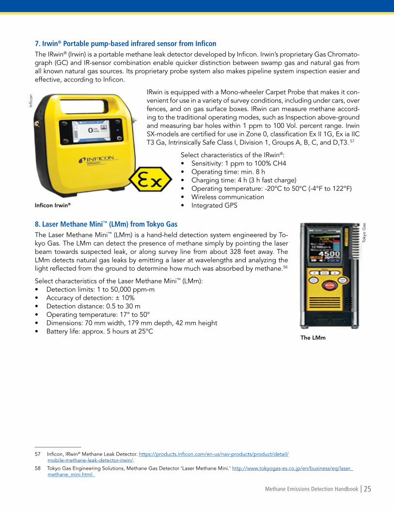
Methane Emissions Detection Handbook | 25
7. Irwin® Portable pump-based infrared sensor from Inficon The IRwin® (Irwin) is a portable methane leak detector developed by Inficon. Irwin’s proprietary Gas Chromato-graph (GC) and IR-sensor combination enable quicker distinction between swamp gas and natural gas from all known natural gas sources. Its proprietary probe system also makes pipeline system inspection easier and effective, according to Inficon.
IRwin is equipped with a Mono-wheeler Carpet Probe that makes it con-venient for use in a variety of survey conditions, including under cars, over fences, and on gas surface boxes. IRwin can measure methane accord-ing to the traditional operating modes, such as Inspection above-ground and measuring bar holes within 1 ppm to 100 Vol. percent range. Irwin SX-models are certified for use in Zone 0, classification Ex II 1G, Ex ia IIC T3 Ga, Intrinsically Safe Class I, Division 1, Groups A, B, C, and D,T3. 57
Select characteristics of the IRwin®: • Sensitivity: 1 ppm to 100% CH4• Operating time: min. 8 h• Charging time: 4 h (3 h fast charge)• Operating temperature: -20°C to 50°C (-4°F to 122°F)• Wireless communication• Integrated GPS
8. Laser Methane Mini™ (LMm) from Tokyo GasThe Laser Methane Mini™ (LMm) is a hand-held detection system engineered by To-kyo Gas. The LMm can detect the presence of methane simply by pointing the laser beam towards suspected leak, or along survey line from about 328 feet away. The LMm detects natural gas leaks by emitting a laser at wavelengths and analyzing the light reflected from the ground to determine how much was absorbed by methane.58
Select characteristics of the Laser Methane Mini™ (LMm): • Detection limits: 1 to 50,000 ppm-m• Accuracy of detection: ± 10%• Detection distance: 0.5 to 30 m• Operating temperature: 17° to 50°• Dimensions: 70 mm width, 179 mm depth, 42 mm height• Battery life: approx. 5 hours at 25°C
57 Inficon, IRwin® Methane Leak Detector. https://products.inficon.com/en-us/nav-products/product/detail/mobile-methane-leak-detector-irwin/.
58 Tokyo Gas Engineering Solutions, Methane Gas Detector ‘Laser Methane Mini.’ http://www.tokyogas-es.co.jp/en/business/eq/laser_methane_mini.html.
Infic
on
Toky
o G
as
Inficon Irwin®
The LMm

26 | Methane Emissions Detection Handbook
9. MIRA PICO Mobile LDS from AerisTechnologies (MIRA PICO)The MIRA PICO Mobile LDS (MIRA PICO) is a re-al-time laser absorption spectrometer with built-in GPS capability developed by Aeris Technology in partnership with Los Alamos National Laboratory and Rice University with funding from the ARPA-E MONITOR’s (Advanced Research Projects Agen-cy – Energy, Methane Observation Networks with Innovative Technology to Obtain Reductions) pro-gram. The MIRA PICO is described as the world’s smallest and most powerful natural gas leak-map-ping tool. The MIRA PICO provides accurate eth-ane/methane ratios at levels rivaling mass spec-
trometric methods, without requiring any sample handling or consumable columns. The MIRA PICO operates in the mid-IR, where methane absorption is 6,000 times stronger than competing approaches in the near-IR. 59
The MIRA PICO applies an integrated artificial neural network inversion approach to enable the laser-based point detector to automatically measure, locate, and quantify methane emissions. It leverages a network of sampling ports to provide real-time information about concentrations at specific areas on the site. Its embedded GPS system acquires spatial coordinates every second, and the analytical instrument aggregates those coordinates to the rest of the measured parameters in a spreadsheet file. In addition, a colorized KML file is continuously updat-ed and can be open directly in Google Earth to map the measurements with unprecedented ease.60
Select characteristics of the MIRA PICO LDS:• Sensitivity: 1 ppb/s• Temperature range: 5°C to 40°C, up to 95% RN (non-condensing)• Concentration range: 0.1 to 10,000 ppm• Size: 11.5” width x 8” depth x 3.75” height
10. MobileGuard™ from ABB/Heath Consultants Inc.MobileGuard™ (MobileGuard) is vehicle-based methane leak detection system developed by ABB. The system is based on ABB's patented Off-Axis Integrated Cavity Output Spectroscopy (OA-ICOS) technique that provides increased sensitivity and precision about 3,000 times greater than legacy methods and enables faster identification of leaks at greater distances away from the source.61
MobileGuard features real-time plotting of indications capable of GIS integration and real-time gas discrimi-nation. It consists of a methane analyzer, a GPS, a sonic anemometer and proprietary leak detection software that presents real-time geospatial maps of multiple gas concentrations.62 Field data readings are stored in MobileGuard’s Cloud platform. A MobileGuard user can have an unlimited number of data analysts who have access to its software. As a security and privacy measure, neither Heath nor ABB have access to the data without the customer’s permission.
59 Advanced Research Projects Agency-Energy, ARPA-E Impacts: A Sampling of Project Outcomes, Volume III. May 7, 2018, https://arpa-e.energy.gov/?q=impact-sheet/bridger-photonics-monitor.
60 Id.
61 Heath Consultants, MobileGuard™ Advanced Mobile Leak Detection. https://heathus.com/wp-content/uploads/MobileGuard.pdf.
62 Id.
ww
w.a
rpa-
eene
rgy.
gov
Hea
th C
onsu
ltant
s
The Aeris Mira PICO Sensor and well pad setup
MobileGuard™

Methane Emissions Detection Handbook | 27
Select characteristics of the MobileGuard™ for methane: • Sensitivity: 2 ppb• Dynamic range: 0.01 – 10,000 ppm• Temperature range: 23°F to 120°F (-5°C to 50°C)• Response time: less than 1 sec• Fast warm-up time: about 5 minutes from power on to data collection• No interferences from ambient compounds or higher hydrocarbons• Calibration: utilizes Off-Axis ICOS, a first principles measurement technique• Calibration free• Power: analyzer and pump only require 180 W
11. Picarro SurveyorTM (Surveyor) from Picarro IncorporatedThe Picarro SurveyorTM (Surveyor) is a Cavity Ring-Down Spectroscopy developed by Picarro Incorporated. Sur-veyor’s detection sensor is 1,000 times more sensitive than traditional ppm-level detectors and, on average, can identify three times the number of hazardous leaks. Surveyor can survey gas mains and service lines and provide immediate leak detection report alerts at driving speeds. After the driving surveys are complete, Surveyor re-
ports leak indications, called LISA inves-tigation markers, which show small, fan-shaped areas with highlighted GIS assets, to search and grade potential leaks.63
Data hosting and processing of the Sur-veyor system are processed through Picarro’s encrypted proprietary man-agement platform called P-Cubed™. P-Cubed is a web-based repository andalgorithmic engine for collecting, cata-loging, processing and displaying visual-ly rich geospatial survey data from multi-ple Picarro Surveyors’ leak investigations.
Select characteristics of the Picarro SurveyorTM: • Superb sensitivity, precision and accuracy with virtually no drift• Fast, continuous, real-time measurements without interference• Large dynamic range with high linearity• Field and laboratory deployable with no consumables• Rugged and insensitive to changes in ambient temperature, pressure or vibration
63 Picarro, Natural Gas Distribution. https://naturalgas.picarro.com/support/library/documents/picarro_surveyor_brochure_flyer.
ww
w.P
icar
ro.c
om
A working diagram of the Picarro Surveyor

28 | Methane Emissions Detection Handbook
12. QM3000 Continuous Methane Detection System from Quanta3The QM3000 is a methane-specific diode laser system developed by Quata3 with funding from the Envi-ronmental Defense Fund. The QM3000 system uses low-cost, low-power, chip-based near-infrared tunable
laser diodes used in fiber-optic communications. The system is stationary, solar powered, and capable of continuous monitoring and measuring.64 Field data collected by the system are automatically stored to the cloud for analysis. If the system detects leaks or an increase methane emission, the system sends out an alert to the assets’ point of contact. All monitoring functions are remotely controlled and tracked.
Select characteristics of the QM3000:• Precision: <50 ppbv @ 1Hz (<20 ppbv typical) • Data Rate: 1 Hz• Power Consumption: 12 W • Online: -20°C to 45°C ambient• Standby: -30°C to 50°C ambient• Size: 14” width x 12” depth x 7” height (Sensor)
13. RMLD-CS™ by Heath Consultants Inc.The RMLD-CS™ (Remote Methane Leak Detector - Complete Solution) is a hand-held, Open-path Laser Sensor developed by Heath Consultants (Heath). According to Heath, the RMLD-CS™ is a highly advanced technology, capable of remotely detecting methane leaks. It combines the receiver and transceiver into a single lightweight, field-rugged instrument. Its remote detection capability allows utility services personnel and first responders to quickly and safely scan for gas leaks.65
Additionally, the remote capability of the RMLD-CS™ makes it easier to survey pipelines from points less than their full lengths. The portability of the RMLD-CS™ also makes it easier to conduct leak surveys in environments such as busy road-ways, yards with dogs, fenced off areas, and other inaccessible places. The rugged characteristic of the instrument enables it to be used under adverse field conditions such as temperature changes, light rain, dust, and fog.66
Select Characteristics of the RMLD-CS™: • Measurement range: 0 to 99,999 ppm-m• Sensitivity: 5 ppm-m at distances from 0 to 50 ft (15 m)• Detection distance: 100 ft (30 m) nominal• Detection alarms: Modes Digital Methane Detection (DMD)• Operating temperature: 0°F to +122°F (-17°C to 50°C)• Communications: Bluetooth 4.2 BLE, WiFi, USB Dual Mode
64 Quanta3, Products. http://www.quanta3.com/products.html.
65 Heath Consultants, RMLD-CS: Remote Methane Leak Detection Complete Solution. March 2019, https://heathus.com/wp-content/uploads/RMLD-CS_0319.pdf.
66 Id.
Q3i
nnov
atio
n
Hea
th C
onsu
ltant
s
Quanta3 Continuous Methane Detection System being field tested at Statoil
Heath Consultants RMLDS CS
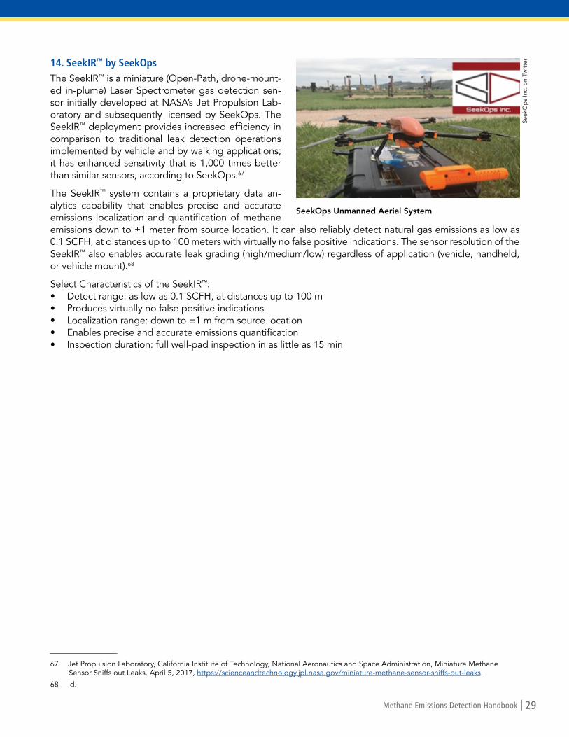
Methane Emissions Detection Handbook | 29
14. SeekIR™ by SeekOps
The SeekIR™ is a miniature (Open-Path, drone-mount-ed in-plume) Laser Spectrometer gas detection sen-sor initially developed at NASA’s Jet Propulsion Lab-oratory and subsequently licensed by SeekOps. The SeekIR™ deployment provides increased efficiency in comparison to traditional leak detection operations implemented by vehicle and by walking applications; it has enhanced sensitivity that is 1,000 times better than similar sensors, according to SeekOps.67
The SeekIR™ system contains a proprietary data an-alytics capability that enables precise and accurate emissions localization and quantification of methane emissions down to ±1 meter from source location. It can also reliably detect natural gas emissions as low as 0.1 SCFH, at distances up to 100 meters with virtually no false positive indications. The sensor resolution of the SeekIR™ also enables accurate leak grading (high/medium/low) regardless of application (vehicle, handheld, or vehicle mount).68
Select Characteristics of the SeekIR™:• Detect range: as low as 0.1 SCFH, at distances up to 100 m• Produces virtually no false positive indications• Localization range: down to ±1 m from source location• Enables precise and accurate emissions quantification• Inspection duration: full well-pad inspection in as little as 15 min
67 Jet Propulsion Laboratory, California Institute of Technology, National Aeronautics and Space Administration, Miniature Methane Sensor Sniffs out Leaks. April 5, 2017, https://scienceandtechnology.jpl.nasa.gov/miniature-methane-sensor-sniffs-out-leaks.
68 Id.
Seek
Op
s In
c. o
n Tw
itter
SeekOps Unmanned Aerial System

30 | Methane Emissions Detection Handbook
Section 6. Collaborations In this section, collaborations to develop innovative and cost-effective methane leak detection technologies are discussed. The primary focus of these collaborations is to subsidize and promote methane detection tech-nological advancement. The timeliness of the collaborations is imperative since methane is about 28 times more powerful than carbon dioxide at warming the Earth, on a 100-year timescale, and more than 80 times more powerful over 20 years.69 Without collaborations, cost is a large barrier to creating and implementing on a larger scale the use of technology that will detect and notify of methane leaks. For example, many compa-nies use infrared cameras, which provide visual identification of leaks. Unfortunately, the cost of these cameras is about $100,000 and they cannot be cost effectively deployed on a continuous basis to monitor all potential sources of emissions.70 Collaborations among federal and state agencies, environmental organizations, the gas industry, and not-for profit corporations work to eliminate or lessen these cost barriers.
A. Methane Detectors ChallengeThe Methane Detectors Challenge (MDC) is a partnership among the Environmental Defense Fund (EDF), oil and gas companies, U.S.-based technology developers, and other experts. Launched in 2014, MDC has suc-cessfully and continually raised awareness and encouraged action through technology innovation in an effort to solve the serious problem of undetected methane emissions along the oil and gas supply chain. The MDC has forged partnerships, leading to technology breakthroughs and innovation in the oil and gas sector. The competition has led to several cost-effective, state-of-the-art options, including sensor and laser technologies that oil and gas companies are adopting.71
In January 2017, Statoil became the first energy producer to purchase and install a new solar-powered tech-nology device to continuously detect methane leaks, reduce emissions, and minimize waste. The device was approved and tested through the MDC and designed by Quanta3. Additionally, Shell launched a Quanta3 solar-powered laser at a well site in Alberta, Canada. The system provides continuous monitoring and protec-tion against methane leaks at the facility, in the same way a smoke or carbon monoxide detector protects your home. Furthermore, California’s PG&E has since installed a low-cost laser technology developed by Acutect Inc., a San Francisco-based startup company all thanks to the MDC.72
B. Advanced Research Projects Agency-EnergySimilar to the collaboration above, Advanced Research Projects Agency-Energy (ARPA-E) advances high-po-tential, high-impact energy technologies that are too early for private-sector investment. ARPA-E provides to researchers funding, technical assistance, and market readiness.73 Starting in 2015 with 11 teams and more than $35 million dollars, ARPA-E’s Methane Observation Networks with Innovative Technology to Obtain Re-ductions (MONITOR) program has helped fund research on developing innovative technologies to cost-ef-fectively and accurately locate and measure methane emissions associated with natural gas production. The MONITOR program has a test site that simulates real-world natural gas operations to test the developing technology.74 Some named participants in this collaboration and recipients of funds are IBM, General Electric, Duke University, and Aeris Technologies.75 One of the technologies to come out of this program was a wireless network of low-cost printed sensor arrays to quantify and locate methane leaks, using a variety of modified carbon nanotube sensors. The combined responses of the sensors in the wireless network provide information
69 U.S. Environmental Protection Agency, Overview of Greenhouse Gases: Methane Emissions. https://www.epa.gov/ghgemissions/overview-greenhouse-gases#methane.
70 Environmental Defense Fund, Methane Detectors Challenge Request for Proposal. 2014, at 7, https://www.edf.org/sites/default/files/mdc_rfp_final.pdf.
71 Environmental Defense Fund, Methane Detectors Challenge. http://business.edf.org/projects/featured/natural-gas/methane-detectors-challenge.
72 Id.
73 Advanced Research Projects Agency-Energy, About. https://arpa-e.energy.gov/?q=arpa-e-site-page/about.
74 Advanced Research Projects Agency-Energy, MONITOR. December 16, 2014, https://arpa-e.energy.gov/?q=arpa-e-programs/monitor.
75 Id.

Methane Emissions Detection Handbook | 31
on location and leak rates for methane and other gases in and around oil and gas infrastructure. This technol-ogy was developed by PARC.76
C. United States Department of Energy and National Energy Technology Lab Investments in Methane Emissions Mitigation and QuantificationThe Consolidated Appropriations Act of 2016 initiated two new programs: (1) Emissions Mitigation from Mid-stream Infrastructure to “develop and test new technologies to reduce methane emissions from midstream infrastructure to enhance the efficiency of natural gas delivery in the United States” and (2) Emissions Quanti-fication from Natural Gas Infrastructure to “improve the quantification of methane emissions across the natural gas value chain reported in the EPA Greenhouse Gas Inventory.”77 The programs were designed to target technologies at intermediate levels of readiness according to DOE’s Technology Readiness Levels scale. In September 2016, the DOE awarded $13 million to 12 multi-year research projects across both program ar-eas.78 An additional $26 million was appropriated to the programs in fiscal years 2017 and 2018.
D. United States Environmental Protection Agency Natural Gas STAR Methane Challenge ProgramThe United States Environmental Protection Agency (EPA) Natural Gas STAR Methane Challenge Program is a larger scale collaboration. The collaboration currently has over 90 participants.79 Program participants trans-parently report systematic and comprehensive actions to reduce methane emissions. The EPA, through this collaboration, creates a space for participants to share information and technology, receive public recognition, and peer networking to foster innovation. By joining the Natural Gas STAR Methane Challenge Program, par-ticipants commit to the following: (1) evaluate their methane emission reduction opportunities, (2) implement methane reduction projects where feasible, and (3) annually report methane emission reduction actions to the EPA. The collective efforts of the collaborating partners resulted in 96.8 Bcf of methane emissions reduction in 2017. The emission reductions are equivalent to additional revenue of approximately $291 million in natural gas sales (assuming an average natural gas price of $3.00 per thousand cubic feet).80
E. Environmental PartnershipA similar size scale collaboration is the Environmental Partnership which, like the collaborations above, brings together companies of all sizes from across the natural gas and oil industry. Beginning in January 2018, 26 nat-ural gas and oil producers, who produce a significant portion of American energy resources signed on. Since the initial start date, the program has grown to over 60 companies who have joined the effort to continuously improve the oil and gas industry’s environmental performance. The Environmental Partnership’s first initiative is focusing on furthering action to reduce air emissions, including methane and volatile organic compounds, associated with natural gas and oil production. To accomplish this, the Environmental Partnership has devel-oped three separate Environmental Performance Programs for participating companies to implement and phase into their operations:
• Leak Program for Natural Gas and Oil Production Sources: Participants will implement monitoring and timely repair of fugitive emissions at selected sites using detection methods and technologies such as Method 21 or Optical Gas Imaging cameras.
76 Advanced Research Projects Agency-Energy, System of Printed Hybrid Intelligent Nano-Chemical Sensors (SPHINCS). December 16, 2014, https://arpa-e.energy.gov/?q=slick-sheet-project/system-printed-hybrid-intelligent-nano-chemical-sensors-sphincs.
77 Smistad, Eric, National Energy Technology Laboratory, presentation to One Future Methane & Climate Strategies Event, DOE Investments in Methane Emissions. May 15, 2018, http://onefuture.us/wp-content/uploads/2018/05/DOE-Investments-in-Methane-Emissions.pdf.
78 U.S. Department of Energy, DOE Announces $13 Million to Quantify and Mitigate Methane Emissions from Natural Gas Infrastructure. September 8, 2016, https://www.energy.gov/articles/doe-announces-13-million-quantify-and-mitigate-methane-emissions-natural-gas-infrastructure.
79 U.S. Environmental Protection Agency, EPA’s Voluntary Methane Programs for the Oil and Natural Gas Industry. https://www.epa.gov/natural-gas-star-program.
80 U.S. Environmental Protection Agency, Natural Gas STAR Program Accomplishments. https://www.epa.gov/natural-gas-star-program/natural-gas-star-program-accomplishments.

32 | Methane Emissions Detection Handbook
• Program to Replace, Remove or Retrofit High-Bleed Pneumatic Controllers: Participants will replace,remove or retrofit high-bleed pneumatic controllers with low or zero-emitting devices.
• Program for Manual Liquids Unloading for Natural Gas Production Sources: Participants will minimizeemissions associated with the removal of liquids that, as a well ages, can build up and restrict natural gas flow.81
F. Natural Resources Defense CouncilThe Natural Resources Defense Council (NRDC) consistently lobbies lawmakers by collaborating with health experts, business executives, labor unions, community leaders, and other allies to demonstrate broad support for reducing methane pollution. The technical experts document proven, cost-effective strategies that oil and gas companies can use to reduce methane waste. The policy experts spotlight the strong legal foundation for methane limits. NRDC calls it “keeping the pressure on.” For example, the NRDC helped persuade the U.S. Environmental Protection Agency to propose limits on new and modified sources of methane pollution through its “keeping the pressure on,” model. NRDC also weighed in on the Bureau of Land Management’s proposed standards for addressing methane waste from oil and gas operations on public lands.82
G. NYSEARCHNYSEARCH is a collaborative research, development, and demonstration (RD&D) organization dedicated to serving its gas utility member companies. Members of NYSEARCH voluntarily participate in projects and pro-grams to target RD&D areas that directly address their unique challenges and opportunities. The core of the NYSEARCH model is joint collaboration and guidance from participating members. The NYSEARCH program area covers a range of chemical sensing and methane sensing products, which includes design, development and testing of successful products such as the RMLD. In addition, NYSEARCH has searched for solutions used by other industries and has identified unique sensing approaches that are now being tested.83 Today, NYSE-ARCH manages more than 30 projects in various stages of development for natural gas LDCs, federal agencies and their manufacturing and commercial partners.84
H. Operations Technology DevelopmentOperations Technology Development (OTD) is a not-for-profit corporation led by 26 members who serve over 50 million natural gas consumers in the United States and Canada managed by the Gas Technology In-stitute. Members of OTD supply 60 percent of the households currently using natural gas. The goals of OTD are to develop, test, and implement new technologies. Since 2003, industry leaders, scientists, technicians, and manufacturers have been working collaboratively within OTD to leverage funds and reduce the financial burden on individual companies. In addition, participants benefit from input from numerous sources, address common regulatory issues, and serve to demonstrate the broad industry support needed to gain the interest of potential product manufacturers.85
I. Pipeline Research Council InternationalPipeline Research Council International (PRCI) is a not-for-profit corporation comprised primarily of energy pipeline companies. PRCI was established in 1952 as the Pipeline Research Committee of the American Gas Association; it became an independent body in 2000. PRCI’s initial charter was to confront the problem of long-running brittle fracture in natural gas transmission pipelines. PRCI’s solution to that problem, within two years, demonstrated the impact and benefits of industry collaboration and the leveraging effect of voluntary funding. Although initially an organization focused solely on pipelines in North America, PRCI began to broad-
81 American Petroleum Institute, Natural Gas, Oil Industry Launch Environmental Partnership to Accelerate Reductions in Methane, VOCs. December 5, 2017, https://www.api.org/news-policy-and-issues/news/2017/12/04/natural-gas-oil-environmental-partnership-accelerate-reductions-methane-vocs.
82 Natural Resources Defense Council, Reduce Methane Pollution and Leaks. https://www.nrdc.org/issues/reduce-methane-pollution-and-leaks.
83 NYSEARCH, Program Areas. https://www.nysearch.org/programs_overview.php#.
84 Northeast Gas Association, NYSEARCH. https://www.northeastgas.org/nysearch.php.
85 Operations Technology Development, About Us. https://www.otd-co.org/about/Pages/default.aspx.

Methane Emissions Detection Handbook | 33
en its membership and technical perspectives beginning in 1980. Today, PRCI is an international organization with members from outside of North America.86
The collaborations above are all pushing toward reducing or stopping methane leaks. The participants in each collaboration are aiding each other in technology development while others push for new or stronger legisla-tion. By leveraging their finances and expertise together, in addition to outside funding and donation, mem-bers of the collaborations are able to focus on the collective goals of information sharing, safety promotion, and environmental impact mitigation.
Section 7. ConclusionThis handbook offers an overview of natural gas infrastructure and the causes and challenges associated with methane leaks, summarizes current commercially available leak detection technologies, highlights emerging technologies, and provides a synopsis of collaborations among the federal government, industry, academia, and other stakeholders. With improved awareness of the market for leak detection tools, state energy regula-tors, natural gas utilities, and other stakeholders can continue to work collaboratively to identify cost-effective solutions to enhance pipeline safety, efficiency, and deliverability. The application of existing and new technol-ogies, as well as continued investment in R&D should, in the end, benefit customers.
Sections 4 and 5 of this handbook offer a digest of numerous methane leak detection technologies and prac-tices that state utility/public service commissions may wish to look at to facilitate reducing leaks. However, this list is in no way intended to be prescriptive or exhaustive. Each state must evaluate and determine what is in its own best interests and what represents the best course of action for its stakeholders. In conclusion, we hope that this handbook serves to educate regulators and promote dialogue on these important issues.
86 Pipeline Research Council International, History & Mission. https://www.prci.org/About/Mission.aspx.

34 | Methane Emissions Detection Handbook
Appendix A. Select Methane Leak Detection Products and Technologies
Product/Technology Application Developer Funder Market Status
Aerial Light detection and ranging system (LIDAR)
Aerial survey Bridger Photonics
DOE:ARPA-E/ MONITOR
Available as a service
Advance leak detection Lidar (ALDL)
Aerial survey Ball Aerospace Ball Aerospace & PHMSA/DOT
Available as a service
Cavity-enhanced laser sensor
Mobile survey, stationary monitoring
LI-CORBiosciences
DOE:ARPA-E/ MONITOR
Unknown
Distributed network of Nano-photonic sensor
Stationary monitoring IBM DOE:ARPA-E/ MONITOR
Field evaluation of prototype
Fixed point laser/ Open-path laser sensor
Stationary monitoring Acutect Inc. and SENSIT Technologies
Environmental Defense Fund
Available as a product
Gas Imaging Camera/Spectral imaging video camera
Stationary monitoring Rebellion Photonics
DOE:ARPA-E/ MONITOR
Available as a product
Gas Tracer/Open Path Laser System (OPLS)
Walking, mobile and aerial survey, stationary monitoring
RKI NASA JPL Available as a product
GAZOSCAN™ Handheld open-path laser sensor
Walking survey GazoMat GazoMat Available as a product
Gas-Trac LZ 50/Handheld open-path laser sensor
Walking survey Sensit Sensit In development
IRwin®/Portable pump-based infrared sensor
Walking survey Inficon Inficon Available as a product
Laser methane mini/ Handheld open-path laser sensor
Walking and aerial survey
Tokyo Gas Tokyo Gas Available as a product
Micro-fabricated electrochemical sensor
Stationary monitoring FullMoon FullMoon In development
Mid-infrared laser source Aerial and mobile survey Maxion Technologies
DOE:ARPA-E/ MONITOR
Laboratory development
MIRA PICO analyzers/ Cell-based mid-infrared laser sensor
Walking, mobile survey, stationary monitoring
Aeris Technologies
DOE:ARPA-E/ MONITOR
Available as a product

Methane Emissions Detection Handbook | 35
Product/Technology Application Developer Funder Market Status
MobileGuard™/Cavity-enhanced laser sensor
Mobile survey ABB ABB Available as a product and aservice
Open-path laser sensor on unmanned aerial vehicle
Aerial survey Physical Sciences Inc.
DOE:ARPA-E/ MONITOR
Field evaluation of prototype
Open-path long-range Frequency comb laser spectroscopy
Stationary monitoring University of Colorado-Boulder
DOE:ARPA-E/ MONITOR
Field evaluation of prototype
Optical fiber combined with laser spectroscopy
Stationary monitoring General Electric DOE:ARPA-E/ MONITOR
Laboratory development
Phase-based colorimetric thin-film sensor
Stationary monitoring BioInspira BioInspira In development
Picarro Surveyor™/Cavity-enhanced laser sensor
Mobile survey, stationary monitoring
Picarro Inc. Picarro Inc. Available as a product
Portable mass spectrometer
Mobile survey, stationary monitoring
Duke University DOE:ARPA-E/ MONITOR
Laboratory prototype
Printed carbon nanotube sensor
Stationary monitoring Palo Alto Research Center
DOE:ARPA-E/ MONITOR
Field evaluation of prototype
Quanta QM3000/ Closed-path laser sensor
Stationary monitoring Quanta3 Environmental Defense Fund
Available as a product
RMLD-CS™/Handheld open-path laser sensor
Walking survey Heath Consultants Inc.
Heath
Consultants Inc.
Available as a product
Satellite-mounted infrared imaging sensor
Space-based and aerial survey
Bluefield Technologies
CubeSats Will launch first micro-satellite in 2020
SeekIR™/Drone-mounted in-plume laser sensor
Aerial survey NASA JPL/ SeekOps
NASA JPL Available as a service
Ultra-low-powered miniature infrared sensor
Stationary monitoring eLichens/Foxberry
eLichens/Foxberry
Available soon

1101 Vermont Ave, NW • Suite 200 • Washington, DC 20005www.naruc.org • (202) 898-2200