Embed Size (px)
Citation preview
Sun Microsystems, Inc.www.sun.com
Submit comments about this document at: http://www.sun.com/hwdocs/feedback
Netra™ 240 Server System Administration Guide
Part No. 817-2700-13December 2005, Revision A

Copyright 2005 Sun Microsystems, Inc., 4150 Network Circle, Santa Clara, California 95054, U.S.A. All rights reserved.
Sun Microsystems, Inc. has intellectual property rights relating to technology that is described in this document. In particular, and without limitation, these intellectual property rights may include one or more of the U.S. patents listed at http://www.sun.com/patents and one or more additional patents or pending patent applications in the U.S. and in other countries.
This document and the product to which it pertains are distributed under licenses restricting their use, copying, distribution, and decompilation. No part of the product or of this document may be reproduced in any form by any means without prior written authorization of Sun and its licensors, if any.
Third-party software, including font technology, is copyrighted and licensed from Sun suppliers.
Parts of the product may be derived from Berkeley BSD systems, licensed from the University of California. UNIX is a registered trademark in the U.S. and in other countries, exclusively licensed through X/Open Company, Ltd.
Sun, Sun Microsystems, the Sun logo, AnswerBook2, docs.sun.com, OpenBoot, Netra, SunVTS, Sun Enterprise Authentication Mechanism, and Solaris are trademarks or registered trademarks of Sun Microsystems, Inc. in the U.S. and in other countries.
All SPARC trademarks are used under license and are trademarks or registered trademarks of SPARC International, Inc. in the U.S. and in other countries. Products bearing SPARC trademarks are based upon an architecture developed by Sun Microsystems, Inc.
The OPEN LOOK and Sun™ Graphical User Interface was developed by Sun Microsystems, Inc. for its users and licensees. Sun acknowledges the pioneering efforts of Xerox in researching and developing the concept of visual or graphical user interfaces for the computer industry. Sun holds a non-exclusive license from Xerox to the Xerox Graphical User Interface, which license also covers Sun’s licensees who implement OPEN LOOK GUIs and otherwise comply with Sun’s written license agreements.
U.S. Government Rights—Commercial use. Government users are subject to the Sun Microsystems, Inc. standard license agreement and applicable provisions of the FAR and its supplements.
DOCUMENTATION IS PROVIDED "AS IS" AND ALL EXPRESS OR IMPLIED CONDITIONS, REPRESENTATIONS AND WARRANTIES, INCLUDING ANY IMPLIED WARRANTY OF MERCHANTABILITY, FITNESS FOR A PARTICULAR PURPOSE OR NON-INFRINGEMENT, ARE DISCLAIMED, EXCEPT TO THE EXTENT THAT SUCH DISCLAIMERS ARE HELD TO BE LEGALLY INVALID.
Copyright 2005 Sun Microsystems, Inc., 4150 Network Circle, Santa Clara, California 95054, Etats-Unis. Tous droits réservés.
Sun Microsystems, Inc. a les droits de propriété intellectuels relatants à la technologie qui est décrit dans ce document. En particulier, et sans la limitation, ces droits de propriété intellectuels peuvent inclure un ou plus des brevets américains énumérés à http://www.sun.com/patents et un ou les brevets plus supplémentaires ou les applications de brevet en attente dans les Etats-Unis et dans les autres pays.
Ce produit ou document est protégé par un copyright et distribué avec des licences qui en restreignent l’utilisation, la copie, la distribution, et la décompilation. Aucune partie de ce produit ou document ne peut être reproduite sous aucune forme, par quelque moyen que ce soit, sans l’autorisation préalable et écrite de Sun et de ses bailleurs de licence, s’il y ena.
Le logiciel détenu par des tiers, et qui comprend la technologie relative aux polices de caractères, est protégé par un copyright et licencié par des fournisseurs de Sun.
Des parties de ce produit pourront être dérivées des systèmes Berkeley BSD licenciés par l’Université de Californie. UNIX est une marque déposée aux Etats-Unis et dans d’autres pays et licenciée exclusivement par X/Open Company, Ltd.
Sun, Sun Microsystems, le logo Sun, AnswerBook2, docs.sun.com, OpenBoot, Netra SunVTS, Sun Enterprise Authentication Mechanism, et Solaris sont des marques de fabrique ou des marques déposées de Sun Microsystems, Inc. aux Etats-Unis et dans d’autres pays.
Toutes les marques SPARC sont utilisées sous licence et sont des marques de fabrique ou des marques déposées de SPARC International, Inc. aux Etats-Unis et dans d’autres pays. Les produits protant les marques SPARC sont basés sur une architecture développée par Sun Microsystems, Inc.
L’interface d’utilisation graphique OPEN LOOK et Sun™ a été développée par Sun Microsystems, Inc. pour ses utilisateurs et licenciés. Sun reconnaît les efforts de pionniers de Xerox pour la recherche et le développement du concept des interfaces d’utilisation visuelle ou graphique pour l’industrie de l’informatique. Sun détient une license non exclusive de Xerox sur l’interface d’utilisation graphique Xerox, cette licence couvrant également les licenciées de Sun qui mettent en place l’interface d ’utilisation graphique OPEN LOOK et qui en outre se conforment aux licences écrites de Sun.
LA DOCUMENTATION EST FOURNIE "EN L’ÉTAT" ET TOUTES AUTRES CONDITIONS, DECLARATIONS ET GARANTIES EXPRESSES OU TACITES SONT FORMELLEMENT EXCLUES, DANS LA MESURE AUTORISEE PAR LA LOI APPLICABLE, Y COMPRIS NOTAMMENT TOUTE GARANTIE IMPLICITE RELATIVE A LA QUALITE MARCHANDE, A L’APTITUDE A UNE UTILISATION PARTICULIERE OU A L’ABSENCE DE CONTREFAÇON.

Contents
Preface xi
1. Troubleshooting Tools 1
Overview of Diagnostic Tools 2
System Prompts 3
Advanced Lights Out Manager 4
Server Status Indicators 4
▼ To Display Locator LED Status 5
▼ To Turn the Locator LED On 5
▼ To Turn the Locator LED Off 5
Alarm Status Indicators 6
Power-On Self-Test Diagnostics 8
Controlling POST Diagnostics 8
▼ To Start POST Diagnostics 10
OpenBoot Commands 11
probe-scsi and probe-scsi-all Commands 11
probe-ide Command 12
show-devs Command 13
▼ To Run OpenBoot Commands 14
OpenBoot Diagnostics 14
iii

▼ To Start OpenBoot Diagnostics 14
Controlling OpenBoot Diagnostics Tests 15
test and test-all Commands 16
OpenBoot Diagnostics Error Messages 17
Operating System Diagnostic Tools 18
Error and System Message Log Files 18
Solaris Software System Information Commands 19
prtconf Command 19
prtdiag Command 21
prtfru Command 23
psrinfo Command 24
showrev Command 25
▼ To Run Solaris Platform System Information Commands 26
Recent Diagnostic Test Results 26
▼ To View Recent POST Test Results 26
OpenBoot Configuration Variables 27
▼ To View and Set OpenBoot Configuration Variables 27
Using the watch-net and watch-net-all Commands to Check the Network Connections 28
Automatic System Recovery 29
Auto-Boot Options 29
Error-Handling Summary 30
Reset Scenarios 31
▼ To Enable ASR 31
▼ To Disable ASR 32
2. SunVTS Software 33
SunVTS Software Overview 33
SunVTS Tests 34
iv Netra 240 Server System Administration Guide • December 2005

SunVTS Software and Security 35
▼ To Determine Whether SunVTS Software Is Installed 35
Installing SunVTS Software 36
Viewing SunVTS Software Documentation 36
3. Advanced Lights Out Manager 37
Advanced Lights Out Manager Overview 37
ALOM Ports 38
Setting the admin Password 39
Basic ALOM Functions 39
▼ To Switch to the ALOM Prompt 40
▼ To Switch to the Server Console Prompt 40
▼ To Take Console Write Capability Away From Another User 40
Automatic Server Restart 41
Environmental Monitoring and Control 41
A. Alarm Relay Output Application Programming Interface 45
Index 51
Contents v

vi Netra 240 Server System Administration Guide • December 2005
Figures
FIGURE 1-1 System Prompt Flow 3
FIGURE 1-2 Location of Front Panel Indicators 4
vii

viii Netra 240 Server System Administration Guide • December 2005

Tables
TABLE 1-1 Summary of Troubleshooting Tools 2
TABLE 1-2 Server Status Indicators (Front and Rear) 4
TABLE 1-3 Alarm Indicators and Dry Contact Alarm States 6
TABLE 1-4 OpenBoot Configuration Variables 9
TABLE 1-5 Keywords for the test-args OpenBoot Configuration Variable 16
TABLE 1-6 Solaris Platform Information Display Commands 26
TABLE 2-1 SunVTS Software Tests 34
TABLE 3-1 Components Monitored by ALOM 38
TABLE 3-2 Netra 240 Server Enclosure Temperature Thresholds 42
ix

x Netra 240 Server System Administration Guide • December 2005

Preface
The Netra 240 Server System Administration Guide is intended to be used by experienced system administrators. It provides a general description of the Netra™ 240 server diagnostics tools and various server administration tasks.
To use the information in this manual you must have a working knowledge of computer network concepts and terms, and advanced knowledge of the Solaris™ Operating System (Solaris OS).
Before You Read This BookThis book does not cover server installation and rack mounting. For detailed information about those topics, refer to the Netra 240 Server Installation Guide (part number 817-2698).
Before following any of the procedures described in this book, be sure you have read Important Safety Information for Sun Hardware Systems (part number 816-7190).
xi

Using UNIX CommandsUse this section to alert readers that not all UNIX commands are provided. For example:
This document might not contain information on basic UNIX® commands and procedures such as shutting down the system, booting the system, and configuring devices. See the following for this information:
■ Software documentation that you received with your system
■ Solaris™ operating environment documentation, which is at
http://docs.sun.com
Shell Prompts
Shell Prompt
C shell machine-name%
C shell superuser machine-name#
Bourne shell and Korn shell $
Bourne shell and Korn shell superuser #
xii Netra 240 Server System Administration Guide • December 2005

Typographic Conventions
Typefacei
i The settings on your browser might differ from these settings.
Meaning Examples
AaBbCc123 The names of commands, files, and directories; on-screen computer output
Edit your.login file.Use ls -a to list all files.% You have mail.
AaBbCc123 What you type, when contrasted with on-screen computer output
% su
Password:
AaBbCc123 Book titles, new words or terms, words to be emphasized. Replace command-line variables with real names or values.
Read Chapter 6 in the User’s Guide.These are called class options.You must be superuser to do this.To delete a file, type rm filename.
Preface xiii

Related Documentation
Accessing Sun DocumentationYou can view, print, or purchase a broad selection of Sun documentation, including localized versions, at:
http://www.sun.com/documentation
Third-Party Web SitesSun is not responsible for the availability of third-party web sites mentioned in this document. Sun does not endorse and is not responsible or liable for any content, advertising, products, or other materials that are available on or through such sites or resources. Sun will not be responsible or liable for any actual or alleged damage or loss caused by or in connection with the use of or reliance on any such content, goods, or services that are available on or through such sites or resources.
Application Title Part Number
Installation overview Netra 240 Server Quick Start Guide 817-3904
Latest product updates Netra 240 Server Release Notes 817-3142
Compliance and safety Important Safety Information for Sun Hardware Systems 816-7190
Netra 240 Server Safety and Compliance Manual 817-3511
Documentation web site location
Sun Netra 240 Server Documentation 817-2697
Installation Netra 240 Server Installation Guide 817-2698
Lights-out management Sun Advanced Lights Out Manager Software User’s Guide for the Netra 240 Server
817-3174
Servicing Netra 240 Server Service Manual 817-2699
xiv Netra 240 Server System Administration Guide • December 2005

Contacting Sun Technical SupportIf you have technical questions about this product that are not answered in this document, go to:
http://www.sun.com/service/contacting
Sun Welcomes Your CommentsSun is interested in improving its documentation and welcomes your comments and suggestions. You can submit your comments by going to:
http://www.sun.com/hwdocs/feedback
Please include the title and part number of your document with your feedback:
Netra 240 Server System Administration Guide, part number 817-2700-xx
Preface xv

xvi Netra 240 Server System Administration Guide • December 2005
CHAPTER 1
Troubleshooting Tools
This chapter describes the diagnostics tools available to the Netra 240 server. The chapter contains the following sections:
■ “Overview of Diagnostic Tools” on page 2
■ “System Prompts” on page 3
■ “Advanced Lights Out Manager” on page 4
■ “Power-On Self-Test Diagnostics” on page 8
■ “OpenBoot Commands” on page 11
■ “OpenBoot Diagnostics” on page 14
■ “Operating System Diagnostic Tools” on page 18
■ “Recent Diagnostic Test Results” on page 26
■ “OpenBoot Configuration Variables” on page 27
■ “Automatic System Recovery” on page 29
1

Overview of Diagnostic ToolsSun provides a range of diagnostic tools for use with the Netra 240 server, as summarized in the following table.
TABLE 1-1 Summary of Troubleshooting Tools
Diagnostic Tool Type Description Accessibility and AvailabilityRemote Capability
ALOM Hardware and software
Monitors environmental conditions, performs basic fault isolation, and provides remote console access.
Can function on standby power and without operating system.
Designed for remote access.
LEDs Hardware Indicate status of overall system and particular components.
Accessed from system chassis. Available anytime power is available.
Local, but can be viewed by means of ALOM.
Power-on self-test (POST)
Firmware Tests core components of system. Runs automatically on startup. Available when the operating system is not running.
Local, but can be viewed by means of ALOM.
OpenBoot commands
Firmware Display various kinds of system information.
Available when the operating system is not running.
Local, but can be accessed by means of ALOM.
OpenBoot diagnostics
Firmware Tests system components, focusing on peripherals and I/O devices.
Runs automatically or interactively. Available when the operating system is not running.
Local, but can be viewed by means of ALOM.
Solaris software commands
Software Display various kinds of system information.
Requires operating system.
Local, but can be accessed by means of ALOM.
SunVTS™ software
Software Exercises and stresses the system, running tests in parallel.
Requires operating system. Optional package.
Viewable and controllable over network.
2 Netra 240 Server System Administration Guide • December 2005
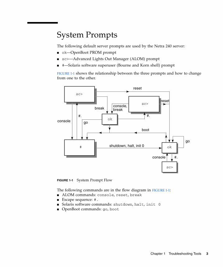
System PromptsThe following default server prompts are used by the Netra 240 server:
■ ok—OpenBoot PROM prompt
■ sc>—Advanced Lights Out Manager (ALOM) prompt
■ #—Solaris software superuser (Bourne and Korn shell) prompt
FIGURE 1-1 shows the relationship between the three prompts and how to change from one to the other.
FIGURE 1-1 System Prompt Flow
The following commands are in the flow diagram in FIGURE 1-1:■ ALOM commands: console, reset, break■ Escape sequence: #. ■ Solaris software commands: shutdown, halt, init 0■ OpenBoot commands: go, boot
sc>
console
console
#
#.
go
sc>
reset
reset
go
boot
console,breakbreak
#.
shutdown, halt, init 0
ok
ok
sc>
#.
Chapter 1 Troubleshooting Tools 3
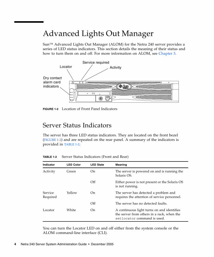
Advanced Lights Out ManagerSun™ Advanced Lights Out Manager (ALOM) for the Netra 240 server provides a series of LED status indicators. This section details the meaning of their status and how to turn them on and off. For more information on ALOM, see Chapter 3.
FIGURE 1-2 Location of Front Panel Indicators
Server Status IndicatorsThe server has three LED status indicators. They are located on the front bezel (FIGURE 1-2) and are repeated on the rear panel. A summary of the indicators is provided in TABLE 1-2.
You can turn the Locator LED on and off either from the system console or the ALOM command-line interface (CLI).
TABLE 1-2 Server Status Indicators (Front and Rear)
Indicator LED Color LED State Meaning
Activity Green On The server is powered on and is running the Solaris OS.
Off Either power is not present or the Solaris OS is not running.
Service Required
Yellow On The server has detected a problem and requires the attention of service personnel.
Off The server has no detected faults.
Locator White On A continuous light turns on and identifies the server from others in a rack, when the setlocator command is used.
CRITICAL
MAJOR
MINOR
USER
Dry contactalarm cardindicators
LocatorService required
Activity
4 Netra 240 Server System Administration Guide • December 2005

▼ To Display Locator LED Status● Do one of the following:
■ As superuser, type:
■ At the ALOM command-line interface, type:
▼ To Turn the Locator LED On● Do one of the following:
■ As superuser, type:
■ At the ALOM command-line interface, type:
▼ To Turn the Locator LED Off● Do one of the following:
■ As superuser, type:
■ At the ALOM command-line interface, type:
# /usr/sbin/locator
sc> showlocator
# /usr/sbin/locator -n
sc> setlocator on
# /usr/sbin/locator -f
sc> setlocator off
Chapter 1 Troubleshooting Tools 5

Alarm Status IndicatorsThe dry contact alarm card has four LED status indicators that are supported by ALOM. They are located vertically on the front bezel (FIGURE 1-2). Information about the alarm indicators and dry contact alarm states is provided in TABLE 1-3. For more information about alarm indicators, see the Sun Advanced Lights Out Manager Software User’s Guide for the Netra 240 Server (part number 817-3174). For more information about an API to control the alarm indicators, see Appendix A.
TABLE 1-3 Alarm Indicators and Dry Contact Alarm States
Indicator and RelayLabels
Indicator Color
Application or Server State Condition or Action
System Indicator State
Alarm Indicator State
Relay NCiv State
Relay NOv State Comments
Critical(Alarm0)
Red Server state (Power on/off and Solaris OS functional/ not functional)
No power input. Off Off Closed Open Default state.
System power off.
Off Offiii Closed Open Input power connected.
System power turns on; Solaris OS not fully loaded.
Off Offiii Closed Open Transient state.
Solaris OS successfully loaded.
On Off Open Closed Normal operating state.
Watchdog timeout.
Off On Closed Open Transient state; reboot Solaris OS.
Solaris OS shutdown initiated by useri.
Off Offiii Closed Open Transient state.
Lost input power.
Off Off Closed Open Default state.
System power shutdown initiated by user.
Off Offiii Closed Open Transient state.
Application state
User sets Critical alarm onii.
— On Closed Open Critical fault detected.
User sets Critical alarm offii.
— Off Open Closed Critical fault cleared.
6 Netra 240 Server System Administration Guide • December 2005

In all cases when the user sets an alarm, a message is displayed on the console. For example, when the critical alarm is set, the following message is displayed on the console:
Note that in some instances when the critical alarm is set, the associated alarm indicator is not lit. This implementation is subject to change in future releases (see Footnote iii of TABLE 1-3).
Major(Alarm1)
Red Application state
User sets Major alarm onii.
— On Open Closed Major fault detected.
User sets Major alarm offii.
— Off Closed Open Major fault cleared.
Minor(Alarm2)
Amber Application state
User sets Minor alarm onii.
— On Open Closed Minor fault detected.
User sets Minor alarm offii.
— Off Closed Open Minor fault cleared.
User(Alarm3)
Amber Application state
User sets User alarm onii.
— On Open Closed User fault detected.
User sets User alarm offii.
— Off Closed Open User fault cleared.
i The user can shut down the system using commands such as init0 and init6. This does not include the system power shutdown.
ii Based on a determination of the fault conditions, the user can turn the alarm on using the Solaris platform alarm API or ALOM CLI. For more information about the alarm API see Appendix A, and for more information about the ALOM CLI, refer to the Sun Advanced Lights Out Manager Software User’s Guide for the Netra 240 Server (part number 817-3174).
iii The implementation of this alarm indicator state is subject to change.
iv NC state is the normally closed state. This state represents the default mode of the relay contacts in the normally closed state.
v NO state is the normally open state. This state represents the default mode of the relay contacts in the normally open state.
SC Alert: CRITICAL ALARM is set
TABLE 1-3 Alarm Indicators and Dry Contact Alarm States (Continued)
Indicator and RelayLabels
Indicator Color
Application or Server State Condition or Action
System Indicator State
Alarm Indicator State
Relay NCiv State
Relay NOv State Comments
Chapter 1 Troubleshooting Tools 7
Power-On Self-Test DiagnosticsPower-on self-test (POST) is a firmware program that helps determine whether a portion of the system has failed. POST verifies the core functionality of the system, including the CPU module(s), motherboard, memory, and some on-board I/O devices. The software then generates messages that can be useful in determining the nature of a hardware failure. You can run POST even if the system is unable to boot.
POST detects most system faults and is located in the motherboard OpenBoot PROM. You can program the OpenBoot software to run POST at power-on by setting two environment variables: the diag-switch? and the diag-level flag. These two variables are stored on the system configuration card (SCC).
Note – The SCC contains information about the system’s identity, including the Host ID, MAC address and NVRAM settings. To increase the speed by which a system can be brought back online, your Sun Service representative might transfer the SCC and the drive on which it resides to another server, enabling it to inherit the old server’s identity without being reconfigured. This procedure should only be done by trained Sun personnel.
POST runs automatically when the system power is applied, or following an automatic system reset, if all of the following conditions apply:
■ diag-switch? is set to true (default is false).■ diag-level is set to min, max or menus (default is min).■ post-trigger matches the class of reset (default is power-on-reset).
If diag-level is set to min or max, POST performs an abbreviated or extended test, respectively.
If diag-level is set to menus, a menu of all the tests executed at power up is displayed.
POST diagnostic and error message reports are displayed on a console.
Controlling POST DiagnosticsYou control POST diagnostics (and other aspects of the boot process) by setting OpenBoot configuration variables. Changes to OpenBoot configuration variables take effect only after the system is restarted. TABLE 1-4 lists the most important and
8 Netra 240 Server System Administration Guide • December 2005

useful of these variables. You can find instructions for changing OpenBoot configuration variables in “To View and Set OpenBoot Configuration Variables” on page 27.
TABLE 1-4 OpenBoot Configuration Variables
OpenBoot Configuration Variable Description and Keywords
auto-boot Determines whether the operating system automatically starts up. Default is true.• true—Operating system automatically starts once firmware tests have finished
running.• false—System remains at ok prompt until you type boot.
diag-level Determines the level or type of diagnostics executed. Default is min.• off—No testing.• min—Only basic tests are run.• max—More extensive tests may be run, depending on the device.• menus— Menu-driven tests at POST levels can be individually run.
diag-script Determines which devices are tested by OpenBoot diagnostics. Default is none.• none—No devices are tested.• normal—On-board (centerplane-based) devices that have self-tests are tested. • all—All devices that have self-tests are tested.
diag-switch? Toggles the system in and out of diagnostic mode. Default is false.• true—Diagnostic mode: POST diagnostics and OpenBoot diagnostics tests are run.• false—Default mode: Do not run POST or OpenBoot diagnostics tests.
post-trigger
obdiag-triggeriThese two variables specify the class of reset event that causes power-on self-tests (or OpenBoot diagnostics tests) to run. These variables can accept single keywords as well as combinations of the first three keywords separated by spaces. For details, see “To View and Set OpenBoot Configuration Variables” on page 27.• error-reset—A reset caused by certain nonrecoverable hardware error
conditions. In general, an error reset occurs when a hardware problem corrupts system state data. Examples include CPU and system watchdog resets, fatal errors, and certain CPU reset events (default).
• power-on-reset—A reset caused by pressing the On/Standby button (default).• user-reset—A reset initiated by the user or the operating system.• all-resets—Any kind of system reset.• none—No power-on self-tests (or OpenBoot diagnostics tests) are run.
input-device Selects where console input is taken from. Default is ttya.• ttya—From built-in SERIAL MGT port.• ttyb—From built-in general purpose serial port (10101).• keyboard—From attached keyboard that is part of a graphics terminal.
Chapter 1 Troubleshooting Tools 9

Note – These variables affect OpenBoot diagnostics tests as well as POST diagnostics.
Once POST diagnostics have finished running, POST reports back the status of each test that was run to the OpenBoot firmware. Control then reverts back to the OpenBoot firmware code.
If POST diagnostics do not uncover a fault, and your server still does not start up, run OpenBoot diagnostics tests.
▼ To Start POST Diagnostics1. Go to the ok prompt.
2. Type:
3. Type:
Where value is min, max, or menus, depending on the quantity of diagnostic information you want to see.
output-device Selects where diagnostic and other console output is displayed. Default is ttya.• ttya—To built-in SERIAL MGT port.• ttyb—To built-in general purpose serial port (10101).• screen—To attached screen that is part of a graphics terminal.ii
i The post-trigger and obdiag-trigger variables are obsolete in releases of OBP after 4.16.2.
ii POST messages cannot be displayed on a graphics terminal. They are sent to ttya even when output-device is set to screen.
ok setenv diag-switch? true
ok setenv diag-level value
TABLE 1-4 OpenBoot Configuration Variables (Continued)
OpenBoot Configuration Variable Description and Keywords
10 Netra 240 Server System Administration Guide • December 2005

4. Type:
The system runs POST diagnostics if post-trigger is set to user-reset. Status and error messages are displayed in the console window. If POST detects an error, it displays an error message describing the failure.
5. When you have finished running POST, restore the value of diag-switch? to false by typing:
Resetting diag-switch? to false minimizes boot time.
OpenBoot CommandsOpenBoot commands are commands you type from the ok prompt. OpenBoot commands that can provide useful diagnostic information are as follows:
■ probe-scsi and probe-scsi-all■ probe-ide■ show-devs
probe-scsi and probe-scsi-all CommandsThe probe-scsi and probe-scsi-all commands diagnose problems with the SCSI devices.
Caution – If you used the halt command or the Stop-A key sequence to reach the ok prompt, issuing the probe-scsi or probe-scsi-all command can hang the system.
The probe-scsi command communicates with all SCSI devices connected to on-board SCSI controllers. The probe-scsi-all command also accesses devices connected to any host adapters installed in PCI slots.
ok reset-all
ok setenv diag-switch? false
Chapter 1 Troubleshooting Tools 11

For any SCSI device that is connected and active, the probe-scsi and probe-scsi-all commands display its loop ID, host adapter, logical unit number, unique world-wide name (WWN), and a device description that includes type and manufacturer.
The following sample output is from the probe-scsi command.
CODE EXAMPLE 1-1 probe-scsi Command Output
The following sample output is from the probe-scsi-all command.
CODE EXAMPLE 1-2 probe-scsi-all Command Output
probe-ide CommandThe probe-ide command communicates with all Integrated Drive Electronics (IDE) devices connected to the IDE bus. This is the internal system bus for media devices such as the DVD drive.
Caution – If you used the halt command or the Stop-A key sequence to reach the ok prompt, issuing the probe-ide command can hang the system.
The following sample output is from the probe-ide command.
{1} ok probe-scsiTarget 0 Unit 0 Disk SEAGATE ST373307LSUN72G 0207Target 1 Unit 0 Disk SEAGATE ST336607LSUN36G 0207{1} ok
{1} ok probe-scsi-all/pci@1c,600000/scsi@2,1
/pci@1c,600000/scsi@2Target 0 Unit 0 Disk SEAGATE ST373307LSUN72G 0207Target 1 Unit 0 Disk SEAGATE ST336607LSUN36G 0207
{1} ok
12 Netra 240 Server System Administration Guide • December 2005
CODE EXAMPLE 1-3 probe-ide Command Output
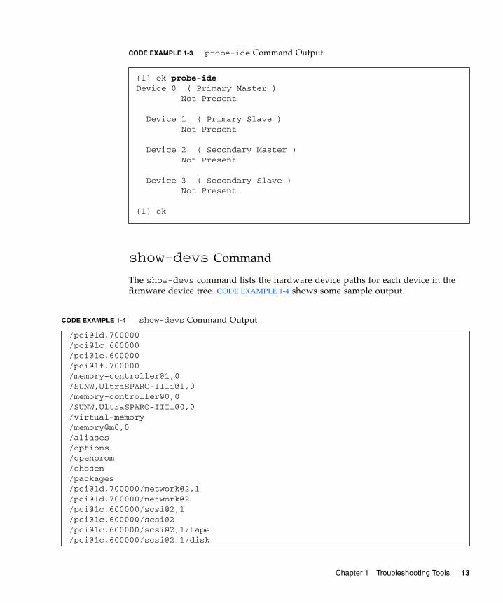
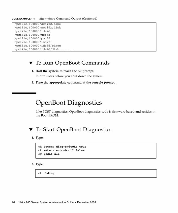
show-devs Command
The show-devs command lists the hardware device paths for each device in the firmware device tree. CODE EXAMPLE 1-4 shows some sample output.
{1} ok probe-ideDevice 0 ( Primary Master ) Not Present
Device 1 ( Primary Slave ) Not Present
Device 2 ( Secondary Master ) Not Present
Device 3 ( Secondary Slave ) Not Present
{1} ok
CODE EXAMPLE 1-4 show-devs Command Output
/pci@1d,700000/pci@1c,600000/pci@1e,600000/pci@1f,700000/memory-controller@1,0/SUNW,UltraSPARC-IIIi@1,0/memory-controller@0,0/SUNW,UltraSPARC-IIIi@0,0/virtual-memory/memory@m0,0/aliases/options/openprom/chosen/packages/pci@1d,700000/network@2,1/pci@1d,700000/network@2/pci@1c,600000/scsi@2,1/pci@1c,600000/scsi@2/pci@1c,600000/scsi@2,1/tape/pci@1c,600000/scsi@2,1/disk
Chapter 1 Troubleshooting Tools 13
▼ To Run OpenBoot Commands1. Halt the system to reach the ok prompt.
Inform users before you shut down the system.
2. Type the appropriate command at the console prompt.
OpenBoot DiagnosticsLike POST diagnostics, OpenBoot diagnostics code is firmware-based and resides in the Boot PROM.
▼ To Start OpenBoot Diagnostics1. Type:
2. Type:
/pci@1c,600000/scsi@2/tape/pci@1c,600000/scsi@2/disk /pci@1e,600000/ide@d/pci@1e,600000/usb@a/pci@1e,600000/pmu@6/pci@1e,600000/isa@7/pci@1e,600000/ide@d/cdrom/pci@1e,600000/ide@d/disk.........
ok setenv diag-switch? trueok setenv auto-boot? falseok reset-all
ok obdiag
CODE EXAMPLE 1-4 show-devs Command Output (Continued)
14 Netra 240 Server System Administration Guide • December 2005

This command displays the OpenBoot diagnostics menu.
Note – If you have a PCI card installed inside the server, additional tests appear on the obdiag menu.
3. Type:
Where n represents the number corresponding to the test you want to run.
A summary of the tests is available. At the obdiag> prompt, type:
Controlling OpenBoot Diagnostics TestsMost of the OpenBoot configuration variables you use to control POST (see TABLE 1-4) also affect OpenBoot diagnostics tests.
■ Use the diag-level variable to control the OpenBoot diagnostics testing level.
■ Use test-args to customize how the tests run.
ok obdiag_____________________________________________________________________________| o b d i a g ||_________________________ __________________________________________________|| | | || 1 flashprom@2,0 | 2 i2c@0,320 | 3 ide@d || 4 network@2 | 5 network@2 | 6 network@2,1 || 7 network@2,1 | 8 rmc-comm@0,3e8 | 9 rtc@0,70 || 10 scsi@2 | 11 scsi@2,1 | 12 serial@0,2e8 || 13 serial@0,3f8 | | ||_________________________|_________________________|________________________|| Commands: test test-all except help what setenv set-default exit ||____________________________________________________________________________|
obdiag> test n
obdiag> help
Chapter 1 Troubleshooting Tools 15

By default, test-args is set to contain an empty string. You can modify test-args using one or more of the reserved keywords shown in TABLE 1-5.
If you want to customize the OpenBoot diagnostics testing, you can set test-args to a comma-separated list of keywords, as in this example:
test and test-all Commands
You can also run OpenBoot diagnostics tests directly from the ok prompt. To do this, type the test command, followed by the full hardware path of the device (or set of devices) to be tested. For example:
To customize an individual test, you can use test-args, as follows:
TABLE 1-5 Keywords for the test-args OpenBoot Configuration Variable
Keyword Description
bist Invokes built-in self-test (BIST) on external and peripheral devices.
debug Displays all debug messages.
iopath Verifies bus and interconnect integrity.
loopback Exercises external loopback path for the device.
media Verifies external and peripheral device media accessibility.
restore Attempts to restore original state of the device if the previous execution of the test failed.
silent Displays only errors rather than the status of each test.
subtests Displays main test and each subtest that is called.
verbose Displays detailed status messages for all tests.
callers=n Displays backtrace of N callers when an error occurs:callers=0—Displays backtrace of all callers before the error.
errors=n Continues executing the test until N errors are encountered:errors=0—Displays all error reports without terminating testing.
ok setenv test-args debug,loopback,media
ok test /pci@x,y/SUNW,qlc@2
ok test /usb@1,3:test-args={verbose,debug}
16 Netra 240 Server System Administration Guide • December 2005

This syntax affects only the current test without changing the value of the test-args OpenBoot configuration variable.
You can test all the devices in the device tree with the test-all command:
CODE EXAMPLE 1-5 displays a sample OpenBoot diagnostics test report where all tests have passed.
CODE EXAMPLE 1-5 OpenBoot Diagnostics Test Report
If you specify a path argument to test-all, only the specified device and its children are tested. The following example shows the command to test the USB bus and all devices with self-tests that are connected to the USB bus:
OpenBoot Diagnostics Error Messages OpenBoot diagnostics error results are reported in a tabular format that contains a short summary of the problem, the hardware device affected, the subtest that failed, and other diagnostic information. CODE EXAMPLE 1-6 displays a sample OpenBoot diagnostics error message.
ok test-all
Hit the spacebar to interrupt testingTesting /pci@1e,600000/isa@7/flashprom@2,0 ............................passedTesting /pci@1e,600000/isa@7/i2c@0,320 ................................passedTesting /pci@1e,600000/ide@d ..........................................passedTesting /pci@1f,700000/network@2 ......................................passedTesting /pci@1d,700000/network@2 ......................................passedTesting /pci@1f,700000/network@2,1 ....................................passedTesting /pci@1d,700000/network@2,1 ....................................passedTesting /pci@1e,600000/isa@7/rmc-comm@0,3e8 ...........................passedTesting /pci@1e,600000/isa@7/rtc@0,70 .................................passedTesting /pci@1c,600000/scsi@2 .........................................passedTesting /pci@1c,600000/scsi@2,1 .......................................passedTesting /pci@1e,600000/isa@7/serial@0,2e8 .............................passedTesting /pci@1e,600000/isa@7/serial@0,3f8 .............................passedPass:1 (of 1) Errors:0 (of 0) Tests Failed:0 Elapsed Time: 0:0:0:25
ok test-all /pci@9,700000/usb@1,3
Chapter 1 Troubleshooting Tools 17

CODE EXAMPLE 1-6 OpenBoot Diagnostics Error Message
Operating System Diagnostic ToolsWhen the system passes OpenBoot diagnostics tests, it attempts to boot the Solaris OS. Once the server is running in multiuser mode, you have access to the software-based diagnostic tools and the SunVTS software. These tools enable you to monitor the server, exercise it, and isolate faults.
Note – If you set the auto-boot? OpenBoot configuration variable to false, the operating system does not boot following completion of the firmware-based tests.
In addition to the tools just mentioned, you can refer to error and system message log files and to Solaris software information commands.
Error and System Message Log FilesError and other system messages are saved in the /var/adm/messages file. Messages are logged to this file from many sources, including the operating system, the environmental control subsystem, and various software applications.
Testing /pci@1e,600000/isa@7/flashprom@2,0
ERROR : FLASHPROM CRC-32 is incorrect SUMMARY : Obs=0x729f6392 Exp=0x3d6cdf53 XOR=0x4ff3bcc1 Addr=0xfeebbffc DEVICE : /pci@1e,600000/isa@7/flashprom@2,0 SUBTEST : selftest:crc-subtest MACHINE : Netra 240 SERIAL# : 52965531 DATE : 03/05/2003 01:33:59 GMT CONTR0LS: diag-level=max test-args=
Error: /pci@1e,600000/isa@7/flashprom@2,0 selftest failed, return code = 1Selftest at /pci@1e,600000/isa@7/flashprom@2,0 (errors=1) .............failedPass:1 (of 1) Errors:1 (of 1) Tests Failed:1 Elapsed Time: 0:0:0:27
18 Netra 240 Server System Administration Guide • December 2005

Solaris Software System Information CommandsThe following Solaris software system information commands display data that you can use when assessing the condition of a Netra 240 server:
■ prtconf ■ prtdiag ■ prtfru ■ psrinfo ■ showrev
This section describes the information that these commands give you. For more information about using these commands, refer to the appropriate man page.
prtconf Command
The prtconf command displays the Solaris software device tree. This tree includes all the devices probed by OpenBoot firmware, as well as additional devices, such as individual disks that only the operating system software recognizes. The output of prtconf also includes the total size of system memory. CODE EXAMPLE 1-7 shows an excerpt of prtconf output.
Chapter 1 Troubleshooting Tools 19

CODE EXAMPLE 1-7 prtconf Command Output
The prtconf command -p option produces output similar to that of the OpenBoot show-devs command. This output lists only those devices compiled by the system firmware.
# prtconf
System Configuration: Sun Microsystems sun4uMemory size: 5120 MegabytesSystem Peripherals (Software Nodes):
SUNW,Netra-240 packages (driver not attached) SUNW,builtin-drivers (driver not attached) deblocker (driver not attached) disk-label (driver not attached) terminal-emulator (driver not attached) dropins (driver not attached) kbd-translator (driver not attached) obp-tftp (driver not attached) SUNW,i2c-ram-device (driver not attached) SUNW,fru-device (driver not attached) ufs-file-system (driver not attached) chosen (driver not attached) openprom (driver not attached) client-services (driver not attached) options, instance #0 aliases (driver not attached) memory (driver not attached) virtual-memory (driver not attached) SUNW,UltraSPARC-IIIi (driver not attached) memory-controller, instance #0 SUNW,UltraSPARC-IIIi (driver not attached) memory-controller, instance #1 pci, instance #0........
20 Netra 240 Server System Administration Guide • December 2005

prtdiag Command
The prtdiag command displays a table of diagnostic information that summarizes the status of system components. The display format used by the prtdiag command can vary depending on what version of the Solaris OS is running on your system. The following code example is an excerpt of some of the output produced by prtdiag on a functional Netra 240 server running Solaris software.
CODE EXAMPLE 1-8 prtdiag Command Output
# prtdiagSystem Configuration: Sun Microsystems sun4u Netra 240System clock frequency: 160 MHZMemory size: 2GB ==================================== CPUs ==================================== E$ CPU CPU Temperature Fan CPU Freq Size Impl. Mask Die Ambient Speed Unit --- -------- ---------- ------ ---- -------- -------- ----- ---- MB/P0 1280 MHz 1MB US-IIIi 2.3 - - MB/P1 1280 MHz 1MB US-IIIi 2.3 - - ================================= IO Devices ================================= Bus FreqBrd Type MHz Slot Name Model--- ---- ---- ---------- ---------------------------- -------------------- 0 pci 66 2 network-pci14e4,1648.108e.16+ 0 pci 66 2 network-pci14e4,1648.108e.16+ 0 pci 66 2 scsi-pci1000,21.1000.1000.1 + 0 pci 66 2 scsi-pci1000,21.1000.1000.1 + 0 pci 66 2 network-pci14e4,1648.108e.16+ 0 pci 66 2 network-pci14e4,1648.108e.16+ 0 pci 33 7 isa/serial-su16550 (serial) 0 pci 33 7 isa/serial-su16550 (serial) 0 pci 33 7 isa/rmc-comm-rmc_comm (seria+ 0 pci 33 13 ide-pci10b9,5229.c4 (ide) ============================ Memory Configuration ============================Segment Table:-----------------------------------------------------------------------Base Address Size Interleave Factor Contains-----------------------------------------------------------------------0x0 1GB 1 GroupID 0 0x1000000000 1GB 1 GroupID 0
Chapter 1 Troubleshooting Tools 21

In addition to the information in CODE EXAMPLE 1-8, prtdiag with the verbose option (-v) also reports on front panel status, disk status, fan status, power supplies, hardware revisions, and system temperatures (see CODE EXAMPLE 1-9).
CODE EXAMPLE 1-9 prtdiag Verbose Output
In the event of an overtemperature condition, prtdiag reports an error in the Status column (CODE EXAMPLE 1-10).
CODE EXAMPLE 1-10 prtdiag Overtemperature Indication Output
Similarly, if a particular component fails, prtdiag reports a fault in the appropriate status column (CODE EXAMPLE 1-11).
Memory Module Groups:--------------------------------------------------ControllerID GroupID Labels--------------------------------------------------0 0 MB/P0/B0/D0,MB/P0/B0/D1Memory Module Groups:--------------------------------------------------ControllerID GroupID Labels--------------------------------------------------1 0 MB/P1/B0/D0,MB/P1/B0/D1
---------------------------------------------------------------Location Sensor Temperature Lo LoWarn HiWarn Hi Status---------------------------------------------------------------MB T_ENC 22C -7C -5C 55C 58C okayMB/P0 T_CORE 57C - - 110C 115C okayMB/P1 T_CORE 54C - - 110C 115C okayPS0 FF_OT - - - - - okayPS1 FF_OT - - - - - okay
---------------------------------------------------------------Location Sensor Temperature Lo LoWarn HiWarn Hi Status---------------------------------------------------------------MB T_ENC 22C -7C -5C 55C 58C okayMB/P0 T_CORE 118C - - 110C 115C failedMB/P1 T_CORE 112C - - 110C 115C warningPS0 FF_OT - - - - - okayPS1 FF_OT - - - - - okay
CODE EXAMPLE 1-8 prtdiag Command Output (Continued)
22 Netra 240 Server System Administration Guide • December 2005

CODE EXAMPLE 1-11 prtdiag Fault Indication Output
prtfru Command
The Netra 240 server maintains a hierarchical list of all field-replaceable units (FRUs) in the system, as well as specific information about various FRUs.
The prtfru command can display this hierarchical list, as well as data contained in the serial electrically-erasable programmable read-only memory (SEEPROM) devices located on many FRUs. CODE EXAMPLE 1-12 shows an excerpt of a hierarchical list of FRUs generated by the prtfru command with the -l option.
Fan Speeds:-----------------------------------------Location Sensor Status Speed-----------------------------------------MB/P0/F0 RS failed 0 rpm MB/P0/F1 RS okay 3994 rpm F2 RS okay 2896 rpm PS0 FF_FAN okay F3 RS okay 2576 rpm PS1 FF_FAN okay ---------------------------------
CODE EXAMPLE 1-12 prtfru -l Command Output
# prtfru -l/frutree/frutree/chassis (fru)/frutree/chassis/MB?Label=MB/frutree/chassis/MB?Label=MB/system-board (container)/frutree/chassis/MB?Label=MB/system-board/SC?Label=SC/frutree/chassis/MB?Label=MB/system-board/SC?Label=SC/sc (fru)/frutree/chassis/MB?Label=MB/system-board/BAT?Label=BAT/frutree/chassis/MB?Label=MB/system-board/BAT?Label=BAT/battery (fru)/frutree/chassis/MB?Label=MB/system-board/P0?Label=P0/frutree/chassis/MB?Label=MB/system-board/P0?Label=P0/cpu (fru)/frutree/chassis/MB?Label=MB/system-board/P0?Label=P0/cpu/F0?Label=F0/frutree/chassis/MB?Label=MB/system-board/P0?Label=P0/cpu/F0?Label=F0/fan-unit (fru)/frutree/chassis/MB?Label=MB/system-board/P0?Label=P0/cpu/F1?Label=F1/frutree/chassis/MB?Label=MB/system-board/P0?Label=P0/cpu/F1?Label=F1/fan-unit (fru)........
Chapter 1 Troubleshooting Tools 23

CODE EXAMPLE 1-13 shows an excerpt of SEEPROM data generated by the prtfru command with the -c option. This output displays only the containers and their data and does not print the FRU tree hierarchy.
CODE EXAMPLE 1-13 prtfru -c Command Output
Data displayed by the prtfru command varies depending on the type of FRU. In general, it includes the following:
■ FRU description■ Manufacturer name and location■ Part number and serial number■ Hardware revision levels
psrinfo Command
The psrinfo command displays the date and time that each CPU is introduced online. With the verbose (-v) option, the command displays additional information about the CPUs, including their clock speed. CODE EXAMPLE 1-14 shows sample output from the psrinfo command with the -v option.
# prtfru -c/frutree/chassis/MB?Label=MB/system-board (container) SEGMENT: SD /ManR /ManR/UNIX_Timestamp32: Mon Dec 2 19:47:38 PST 2002 /ManR/Fru_Description: FRUID,INSTR,M’BD,2X1.28GHZ,CPU /ManR/Manufacture_Loc: Hsinchu,Taiwan /ManR/Sun_Part_No: 3753120 /ManR/Sun_Serial_No: 000615 /ManR/Vendor_Name: Mitac International /ManR/Initial_HW_Dash_Level: 02 /ManR/Initial_HW_Rev_Level: 0E /ManR/Fru_Shortname: MOTHERBOARD /SpecPartNo: 885-0076-11/frutree/chassis/MB?Label=MB/system-board/P0?Label=P0/cpu/B0?Label=B0/bank/D0?Label=D0/mem-module (container)/frutree/chassis/MB?Label=MB/system-board/P0?Label=P0/cpu/B0?Label=B0/bank/D1?Label=D1/mem-module (container)........
24 Netra 240 Server System Administration Guide • December 2005

CODE EXAMPLE 1-14 psrinfo -v Command Output
showrev Command
The showrev command displays revision information for the current hardware and software. CODE EXAMPLE 1-15 shows sample output from the showrev command.
CODE EXAMPLE 1-15 showrev Command Output
When used with the -p option, the showrev command displays installed patches. CODE EXAMPLE 1-16 shows a partial sample output from the showrev command with the -p option.
CODE EXAMPLE 1-16 showrev -p Command Output
# psrinfo -vStatus of processor 0 as of: 07/28/2003 14:43:29 Processor has been on-line since 07/21/2003 18:43:37. The sparcv9 processor operates at 1280 MHz, and has a sparcv9 floating point processor.Status of processor 1 as of: 07/28/2003 14:43:29 Processor has been on-line since 07/21/2003 18:43:36. The sparcv9 processor operates at 1280 MHz, and has a sparcv9 floating point processor
# showrevHostname: vsp78-36Hostid: 8328c87bRelease: 5.8Kernel architecture: sun4uApplication architecture: sparcHardware provider: Sun_MicrosystemsDomain: vsplab.SFBay.Sun.COMKernel version: SunOS 5.8 Generic 108528-18 November 2002
Patch: 109729-01 Obsoletes: Requires: Incompatibles: Packages: SUNWcsuPatch: 109783-01 Obsoletes: Requires: Incompatibles: Packages: SUNWcsuPatch: 109807-01 Obsoletes: Requires: Incompatibles: Packages: SUNWcsuPatch: 109809-01 Obsoletes: Requires: Incompatibles: Packages: SUNWcsuPatch: 110905-01 Obsoletes: Requires: Incompatibles: Packages: SUNWcsuPatch: 110910-01 Obsoletes: Requires: Incompatibles: Packages: SUNWcsuPatch: 110914-01 Obsoletes: Requires: Incompatibles: Packages: SUNWcsuPatch: 108964-04 Obsoletes: Requires: Incompatibles: Packages: SUNWcsr
Chapter 1 Troubleshooting Tools 25

▼ To Run Solaris Platform System Information Commands
● At a command prompt, type the command for the kind of system information you want to display.
For more information, see “Solaris Software System Information Commands” on page 19. See TABLE 1-6 for a summary of the commands.
Recent Diagnostic Test ResultsSummaries of the results from the most recent power-on self-test (POST) diagnostics tests are saved across power cycles.
▼ To View Recent POST Test Results1. Go to the ok prompt.
TABLE 1-6 Solaris Platform Information Display Commands
Command What It Displays What to Type Notes
prtconf System configuration information
/usr/sbin/prtconf —
prtdiag Diagnostic and configuration information
/usr/platform/sun4u/sbin/prtdiag
Use the -v option for additional detail.
prtfru FRU hierarchy and SEEPROM memory contents
/usr/sbin/prtfru Use the -l option to display hierarchy. Use the -c option to display SEEPROM data.
psrinfo Date and time each CPU came online; processor clock speed
/usr/sbin/psrinfo Use the -v option to obtain clock speed and other data.
showrev Hardware and software revision information
/usr/bin/showrev Use the -p option to show software patches.
26 Netra 240 Server System Administration Guide • December 2005

2. To see a summary of the most recent POST results, type:
This command produces a system-dependent list of hardware components, along with an indication of which components passed and which failed POST diagnostics tests.
OpenBoot Configuration VariablesSwitches and diagnostic configuration variables stored in the IDPROM determine how and when POST diagnostics and OpenBoot diagnostics tests are performed. This section explains how to access and modify OpenBoot configuration variables. For a list of important OpenBoot configuration variables, see TABLE 1-4.
Changes to OpenBoot configuration variables take effect at the next reboot.
▼ To View and Set OpenBoot Configuration Variables
● Halt the server to display the ok prompt.
■ To display the current values of all OpenBoot configuration variables, use the printenv command.
The following example shows a short excerpt of this command’s output.
■ To set or change the value of an OpenBoot configuration variable, use the setenv command:
ok show-post-results
ok printenvVariable Name Value Default Value
diag-level min mindiag-switch? false false
ok setenv diag-level maxdiag-level = max
Chapter 1 Troubleshooting Tools 27

■ To set OpenBoot configuration variables that accept multiple keywords, separate keywords with a space.
Using the watch-net and watch-net-all Commands to Check the Network ConnectionsThe watch-net diagnostics test monitors Ethernet packets on the primary network interface. The watch-net-all diagnostics test monitors Ethernet packets on the primary network interface and on any additional network interfaces connected to the system board. Good packets received by the system are indicated by a period (.). Errors such as the framing error and the cyclic redundancy check (CRC) error are indicated with an X and an associated error description.
● To start the watch-net diagnostic test, type the watch-net command at the ok prompt (CODE EXAMPLE 1-17).
● To start the watch-net-all diagnostic test, type watch-net-all at the ok prompt (CODE EXAMPLE 1-18).
CODE EXAMPLE 1-17 watch-net Diagnostic Output Message
{0} ok watch-netInternal loopback test -- succeeded.Link is -- upLooking for Ethernet Packets.‘.’ is a Good Packet. ‘X’ is a Bad Packet.Type any key to stop.................................
CODE EXAMPLE 1-18 watch-net-all Diagnostic Output Message
{0} ok watch-net-all/pci@1f,0/pci@1,1/network@c,1Internal loopback test -- succeeded.Link is -- up Looking for Ethernet Packets.‘.’ is a Good Packet. ‘X’ is a Bad Packet.Type any key to stop.
28 Netra 240 Server System Administration Guide • December 2005

Automatic System Recovery
Note – Automatic System Recovery (ASR) is not the same as Automatic Server Restart, which the Netra 240 server also supports. For information about Automatic Server Restart, see Chapter 3.
Automatic System Recovery (ASR) consists of self-test features and an auto-configuring capability to detect failed hardware components and unconfigure them. By enabling ASR, the server is able to resume operating after certain nonfatal hardware faults or failures have occurred.
If a component is monitored by ASR and the server is capable of operating without it, the server automatically reboots if that component develops a fault or fails. This capability prevents a faulty hardware component from preventing the entire system from operating or causing the system to fail repeatedly.
If a fault is detected during the power-on sequence, the faulty component is disabled. If the system remains capable of functioning, the boot sequence continues.
To support this degraded boot capability, the OpenBoot firmware uses the 1275 Client Interface (by means of the device tree) to mark a device as either failed or disabled, by creating an appropriate status property in the device tree node. The Solaris OS does not activate a driver for any subsystem marked in this way.
As long as a failed component is electrically dormant (not causing random bus errors or signal noise, for example), the system reboots automatically and resumes operation while a service call is made.
Once a failed or disabled device is replaced with a new one, the OpenBoot firmware automatically modifies the status of the device upon reboot.
Note – ASR is not enabled until you activate it (see “To Enable ASR” on page 31).
Auto-Boot OptionsThe auto-boot? setting controls whether the firmware automatically boots the operating system after each reset. The default setting is true.
Chapter 1 Troubleshooting Tools 29

The auto-boot-on-error? setting controls whether the system attempts a degraded boot when a subsystem failure is detected. Both the auto-boot? and auto-boot-on-error? settings must be set to true to enable an automatic degraded boot.
● To set the switches, type:
Note – The default setting for auto-boot-on-error? is false. Therefore, the system does not attempt a degraded boot unless you change this setting to true. In addition, the system does not attempt a degraded boot in response to any fatal non-recoverable error, even if degraded booting is enabled. For examples of fatal non-recoverable errors, see “Error-Handling Summary” on page 30.
Error-Handling SummaryError handling during the power-on sequence can be summarized in the following three ways:
■ If no errors are detected by POST or OpenBoot diagnostics, the system attempts to boot if auto-boot? is true.
■ If only nonfatal errors are detected by POST or OpenBoot diagnostics, the system attempts to boot if auto-boot? is true and auto-boot-on-error? is true.
Note – If POST or OpenBoot diagnostics detects a nonfatal error associated with the normal boot device, the OpenBoot firmware automatically unconfigures the failed device and tries the next-in-line boot device, as specified by the boot-device configuration variable.
■ If a fatal error is detected by POST or OpenBoot diagnostics, the system does not boot regardless of the settings of auto-boot? or auto-boot-on-error? Fatal nonrecoverable errors include the following:
■ Failure of all CPUs■ Failure of all logical memory banks■ Failure of flash RAM cyclical redundancy check (CRC)■ Failure of critical field-replaceable unit (FRU) PROM configuration data■ Failure of critical application-specific integrated circuit (ASIC)
ok setenv auto-boot? trueok setenv auto-boot-on-error? true
30 Netra 240 Server System Administration Guide • December 2005

Reset ScenariosThree OpenBoot configuration variables—diag-switch?, obdiag-trigger, and post-trigger—control how the system runs firmware diagnostics in response to system reset events.
The standard system reset protocol bypasses POST and OpenBoot diagnostics unless diag-switch? is set to true. The default setting for this variable is false. Because ASR relies on firmware diagnostics to detect faulty devices, diag-switch? must be set to true for ASR to run. For instructions, see “To Enable ASR” on page 31.
To control which reset events, if any, automatically initiate firmware diagnostics, use obdiag-trigger and post-trigger. For detailed explanations of these variables and their uses, see “Controlling POST Diagnostics” on page 8 and “Controlling OpenBoot Diagnostics Tests” on page 15.
▼ To Enable ASR1. At the system ok prompt, type:
2. Set the obdiag-trigger variable to power-on-reset, error-reset, or user-reset.
For example, type:
3. Type:
The system permanently stores the parameter changes and boots automatically if the OpenBoot variable auto-boot? is set to true (its default value).
Note – To store parameter changes, you can also power-cycle the system by using the front panel On/Standby button.
ok setenv diag-switch? trueok setenv auto-boot? trueok setenv auto-boot-on-error? true
ok setenv obdiag-trigger user-reset
ok reset-all
Chapter 1 Troubleshooting Tools 31

▼ To Disable ASR1. At the system ok prompt, type:
2. Type:
The system permanently stores the parameter change.
Note – To store parameter changes, you can also power-cycle the system by using the front panel On/Standby button.
ok setenv diag-switch? false
ok reset-all
32 Netra 240 Server System Administration Guide • December 2005

CHAPTER 2
SunVTS Software
This chapter describes SunVTS. The following topics are discussed in this chapter:
■ “SunVTS Software Overview” on page 33■ “SunVTS Tests” on page 34■ “SunVTS Software and Security” on page 35■ “Installing SunVTS Software” on page 36■ “Viewing SunVTS Software Documentation” on page 36
SunVTS Software OverviewThe SunVTS 5.1 Patch Set 5 (PS5) software, and future compatible versions, are supported on the Netra 240 server.
The SunVTS software, the Sun Validation Test Suite, is an online diagnostics tool for verifying the configuration and functionality of hardware controllers, devices, and platforms. It runs in the Solaris OS and has the following interfaces:
■ Command-line interface (CLI)■ Serial (tty) interface
The SunVTS software suite performs system and peripherals stress testing. You can view and control a SunVTS software session over a network. Using a remote machine, you can view the progress of a testing session, change testing options, and control all testing features of another machine on the network.
You can run SunVTS software in three test modes:
■ Connection mode verifies the presence of device controllers. This typically takes no more than a few minutes and is a good way to run a “sanity check” on the system connections.
■ Functional mode exercises only the specific subsystems you choose. This is the default mode.
33

■ Auto Config mode automatically detects all subsystems and exercises them in one of two ways:
■ Confidence testing – Performs one pass of tests on all subsystems, and then stops. For typical system configurations, this requires one or two hours.
■ Comprehensive testing – Tests all subsystems repeatedly for up to 24 hours.
Since SunVTS software can run many tests in parallel and consume many system resources, you should take care when using it on a production system. If you are stress-testing a system using SunVTS software’s Comprehensive test mode, do not run anything else on that system at the same time.
A server must be running the Solaris OS for SunVTS software to be able to test it. Since SunVTS software packages are optional, they may not be installed on your system. For instructions, see “To Determine Whether SunVTS Software Is Installed” on page 35.
SunVTS TestsYou can use the SunVTS software to view and control testing sessions on a remotely connected server. TABLE 2-1 lists some of the tests that are available.
TABLE 2-1 SunVTS Software Tests
SunVTS Software Test Description
cputest Tests the CPU.
disktest Tests the local disk drives.
dvdtest Tests the DVD-ROM drive.
n240atest Tests the alarm card for alarm relays, LEDs, and FRU ID.
fputest Tests the floating-point unit.
nettest Tests the Ethernet hardware on the system board and the networking hardware on any optional PCI cards.
netlbtest Performs a loopback test to check that the Ethernet adapter can send and receive packets.
pmem Tests the physical memory (read only).
sutest Tests the server’s on-board serial ports.
vmem Tests the virtual memory (a combination of the swap partition and the physical memory).
34 Netra 240 Server System Administration Guide • December 2005

SunVTS Software and SecurityDuring SunVTS software installation, you must choose between basic or Sun Enterprise Authentication Mechanism™ (SEAM) security. Basic security uses a local security file in the SunVTS software installation directory to limit the users, groups, and hosts permitted to use SunVTS software. SEAM security is based on the standard network authentication protocol Kerberos and provides secure user authentication, data integrity, and privacy for transactions over networks.
If your site uses SEAM security, you must have the SEAM client and server software installed in your networked environment and configured properly in both Solaris software and SunVTS software. If your site does not use SEAM security, do not choose the SEAM option during SunVTS software installation.
If you enable the wrong security scheme during installation, or if you improperly configure the security scheme you choose, you may find yourself unable to run SunVTS software tests. For more information, see the SunVTS User’s Guide and the instructions accompanying the SEAM software.
▼ To Determine Whether SunVTS Software Is Installed
● Type:
■ If SunVTS software is loaded, information about the package is displayed.■ If SunVTS software is not loaded, you see the following error message:
env6test Tests the environmental devices.
ssptest Tests ALOM hardware devices.
i2c2test Tests I2C devices for correct operation.
# pkginfo -l SUNWvts
ERROR: information for “SUNWvts” was not found
TABLE 2-1 SunVTS Software Tests (Continued)
SunVTS Software Test Description
Chapter 2 SunVTS Software 35

Installing SunVTS SoftwareBy default, the SunVTS software is not installed on the Netra 240 server. However, it is available on the Solaris OS supplement CD, and the latest revisions can be downloaded from the following web site:
http://www.sun.com/oem/products/vts/
Note – The SunVTS 5.1 Patch Set 5 (PS5) software, and future compatible versions, are supported on the Netra 240 server.
To find out more about using SunVTS software, refer to the SunVTS documentation that corresponds to the Solaris software release that you are running. You can also find additional information about the SunVTS software, as well as installation instructions, on the above web site.
Viewing SunVTS Software DocumentationThe SunVTS Software documents are included on the software supplement CD that is part of each Solaris media kit release. These documents are also available at http://docs.sun.com.
For further information, you can also consult the following SunVTS software documents:
■ SunVTS User’s Guide explains how to install, configure, and run the SunVTS diagnostic software.
■ SunVTS Quick Reference Card provides an overview of how to use the SunVTS interface.
■ SunVTS Test Reference Manual provides details about each individual SunVTS test.
36 Netra 240 Server System Administration Guide • December 2005

CHAPTER 3
Advanced Lights Out Manager
This chapter gives an overview of the Sun™ Advanced Lights Out Manager (ALOM) software. The chapter covers the following topics:
■ “Advanced Lights Out Manager Overview” on page 37
■ “ALOM Ports” on page 38
■ “Setting the admin Password” on page 39
■ “Basic ALOM Functions” on page 39
■ “Automatic Server Restart” on page 41
■ “Environmental Monitoring and Control” on page 41
Advanced Lights Out Manager OverviewThe Netra 240 server is shipped with the Sun Advanced Lights Out Manager installed. The system console is directed to ALOM by default and is configured to show server console information on start-up.
ALOM enables you to monitor and control your server over either a serial connection (using the SERIAL MGT port) or an Ethernet connection (using the NET MGT port). For information on configuring an Ethernet connection, refer to the Sun Advanced Lights Out Manager Software User’s Guide for the Netra 240 Server (817-3174).
Note – The ALOM serial port, labeled SERIAL MGT, is for server management only. If you need a general-purpose serial port, use the serial port labeled 10101.
37

You can configure ALOM to send email notification of hardware failures and other events related to the server or to ALOM.
The ALOM circuitry uses standby power from the server, with the following results:
■ ALOM is active as soon as the server is connected to a power source and until the power cable is unplugged.
■ ALOM firmware and software continue to be effective when the server operating system goes offline.
TABLE 3-1 lists the components that are monitored by ALOM and the information that the software provides for each component.
ALOM PortsThe default management port is labeled SERIAL MGT. This port uses an RJ-45 connector and is for server management only; it supports only ASCII connections to an external console. Use this port the first time you operate the server.
Another serial port—labeled 10101—is available for general purpose serial data transfer. This port uses a DB-9 connector. For information about pinouts, refer to the Netra 240 Server Installation Guide (part number 817-2698).
TABLE 3-1 Components Monitored by ALOM
Component Information Provided
Hard drives Presence and status
System and CPU fans Speed and status
CPUs Presence, temperature, and any thermal warning or failure conditions
Power supplies Presence and status
System temperature Ambient temperature and any thermal warning or failure conditions
Server front panel Rotary switch position and LED status
Voltage Status and thresholds
SCSI and USB circuit breakers Status
Dry contact relay alarms Status
38 Netra 240 Server System Administration Guide • December 2005

In addition, the server has one 10BASE-T Ethernet management domain interface, labeled NET MGT. To use this port, ALOM configuration is required. For information, see the Sun Advanced Lights Out Manager Software User’s Guide for the Netra 240 Server (part number 817-3174).
Setting the admin PasswordWhen you switch to the ALOM software after initial power-on, you see the sc> prompt. At this point, you can execute commands that require no user permissions. (Refer to the Sun Advanced Lights Out Manager Software User’s Guide for the Netra 240 Server, part number 817-3174, for a list of commands.) When you attempt to execute any command that requires user permissions, you are prompted to set a password for user admin.
● If you are prompted to do so, set a password for the admin user.
The password must contain the following:
■ At least two alphabetic characters■ At least one numeric or one special character ■ Between six and eight characters
Once the password is set, the admin user has full permissions and can execute all ALOM CLI commands. The user is prompted to log in with the admin password when subsequently switching to ALOM.
Basic ALOM FunctionsThis section covers some basic ALOM functions. For comprehensive documentation, refer to the Sun Advanced Lights Out Manager Software User’s Guide for the Netra 240 Server (part number 817-3174) and the Netra 240 Server Release Notes (817-3142).
Chapter 3 Advanced Lights Out Manager 39
▼ To Switch to the ALOM Prompt● At a command prompt, type the following #. keystroke sequence:
Note – When you switch to the ALOM prompt, you are logged in with the userid admin. See “Setting the admin Password” on page 39.
▼ To Switch to the Server Console Prompt● Type:
More than one ALOM user can be connected to the server console at a time, but only one user is permitted to type input characters to the console.
If another user is logged in and has write capability, you see the following message below after typing the console command:
▼ To Take Console Write Capability Away From Another User
● Type:
# #.
sc> console
sc> Console session already in use. [view mode]
sc> console -f
40 Netra 240 Server System Administration Guide • December 2005
Automatic Server Restart
Note – Automatic System Recovery (ASR) is not the same as Automatic Server Restart, which the Netra 240 server also supports.
Automatic Server Restart is a component of ALOM. It monitors the Solaris OS while it is running and, by default, syncs the file systems and restarts the server if it fails.
ALOM uses a watchdog process to monitor the kernel only. ALOM does not restart the server if a process hangs and the kernel is still running. The ALOM watchdog parameters for the watchdog patting interval and the watchdog timeout are not user configurable.
If the kernel hangs and the watchdog times out, ALOM reports and logs the event and performs one of three user configurable actions:
■ xir—This default action causes the server to sync the file systems and restart. If the system hangs, ALOM reverts to a hard reset after 15 minutes.
■ Reset—This is a hard reset and results in a rapid system recovery, but diagnostic data regarding the hang is not stored, and major damage may result.
■ None—The system is left in the hung state indefinitely after the watchdog timeout has been reported.
For more information, see the sys_autorestart section of the Sun Advanced Lights Out Manager Software User’s Guide for the Netra 240 Server (part number 817-3174).
For instructions on using Automatic System Recovery (ASR), see Chapter 1.
Environmental Monitoring and ControlThe Netra 240 server features an environmental monitoring subsystem designed to protect the server and its components against the following:
■ Extreme temperatures■ Lack of adequate airflow through the system■ Operating with missing or misconfigured components■ Power supply failures■ Internal hardware faults
Chapter 3 Advanced Lights Out Manager 41

Monitoring and control capabilities are handled by the ALOM firmware, which ensures that monitoring capabilities remain operational even if the system has halted or is unable to boot. Also, monitoring the system from the ALOM firmware frees the system to dedicate CPU and memory resources to the operating system and application software.
The environmental monitoring subsystem uses an industry-standard I2C bus. The I2C bus is a simple two-wire serial bus used throughout the system to enable the monitoring and control of temperature sensors, fans, power supplies, status LEDs, and the front panel system control rotary switch.
The server contains three temperature sensors that monitor the ambient temperature of the server and the die temperature of the two CPUs. The monitoring subsystem polls each sensor and uses the sampled temperatures to report and respond to any overtemperature or undertemperature conditions. Additional I2C devices detect component presence and component faults.
The hardware and software together ensure that the temperatures within the enclosure do no exceed predetermined “safe operation” ranges. If the temperature observed by a sensor falls below a low-temperature warning threshold or rises above a high-temperature warning threshold, the monitoring subsystem software lights the system Service Required LEDs on the front and back panels. If the temperature condition persists and reaches a high or low soft shut-down temperature threshold, the system initiates a graceful system shut down. If the temperature reaches a high or low hard temperature threshold, the system initiates a forced system shut down.
Error and warning messages are sent to the system console and are logged in the /var/adm/messages file, and Service Required LEDs remain lit after an automatic system shutdown to aid in problem diagnosis.
The types of messages that are sent to the system console and are logged in the /var/adm/messages file depend on how you set the sc_clieventlevel and sys_eventlevel ALOM user variables. For information about setting these variables, refer to the Sun Advanced Lights Out Manager Software User’s Guide for the Netra 240 Server (817-3174).
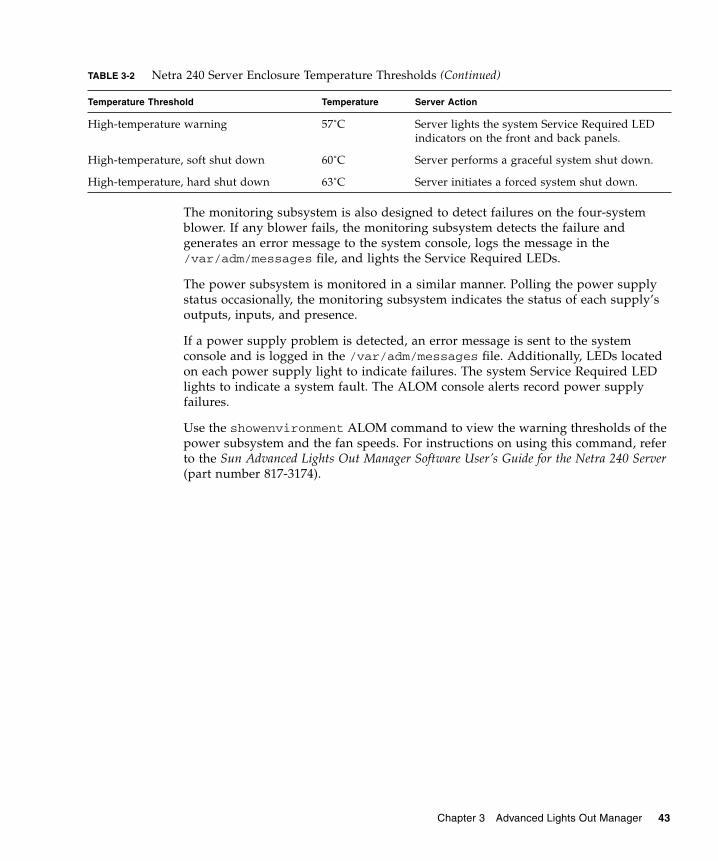
TABLE 3-2 Netra 240 Server Enclosure Temperature Thresholds
Temperature Threshold Temperature Server Action
Low-temperature, hard shut down -11˚C Server initiates a forced system shut down.
Low-temperature, soft shut down -9˚C Server performs a graceful system shut down.
Low-temperature warning -7˚C Server lights the system Service Required LED indicators on the front and back panels.
42 Netra 240 Server System Administration Guide • December 2005
The monitoring subsystem is also designed to detect failures on the four-system blower. If any blower fails, the monitoring subsystem detects the failure and generates an error message to the system console, logs the message in the /var/adm/messages file, and lights the Service Required LEDs.
The power subsystem is monitored in a similar manner. Polling the power supply status occasionally, the monitoring subsystem indicates the status of each supply’s outputs, inputs, and presence.
If a power supply problem is detected, an error message is sent to the system console and is logged in the /var/adm/messages file. Additionally, LEDs located on each power supply light to indicate failures. The system Service Required LED lights to indicate a system fault. The ALOM console alerts record power supply failures.
Use the showenvironment ALOM command to view the warning thresholds of the power subsystem and the fan speeds. For instructions on using this command, refer to the Sun Advanced Lights Out Manager Software User’s Guide for the Netra 240 Server (part number 817-3174).
High-temperature warning 57˚C Server lights the system Service Required LED indicators on the front and back panels.
High-temperature, soft shut down 60˚C Server performs a graceful system shut down.
High-temperature, hard shut down 63˚C Server initiates a forced system shut down.
TABLE 3-2 Netra 240 Server Enclosure Temperature Thresholds (Continued)
Temperature Threshold Temperature Server Action
Chapter 3 Advanced Lights Out Manager 43

44 Netra 240 Server System Administration Guide • December 2005

APPENDIX A
Alarm Relay Output Application Programming Interface
This appendix provides a sample program (CODE EXAMPLE A-1) that illustrates how to get/set the status of the alarms. The application can use LOMIOCALSTATE ioctl function to obtain the status of each alarm and the LOMIOCALCTL ioctl function to set the alarms individually. For more details on the Alarm Indicators, see the Netra 240 Server Service Manual (817-2699).
CODE EXAMPLE A-1 Example Program for get/set Status of the Alarms
#include <sys/types.h>#include <string.h>#include <stdlib.h>#include <sys/unistd.h>#include <fcntl.h>#include "lom_io.h"
#define ALARM_INVALID -1#define LOM_DEVICE "/dev/lom"
static void usage();static void get_alarm(const char *alarm);static int set_alarm(const char *alarm, const char *alarmval);static int parse_alarm(const char *alarm);static int lom_ioctl(int ioc, char *buf);static char *get_alarmval(int state);static void get_alarmvals();
main(int argc, char *argv[]){
if (argc < 3) { usage(); if (argc == 1)
45

get_alarmvals(); exit(1); }
if (strcmp(argv[1], "get") == 0) { if (argc != 3) { usage(); exit (1); } get_alarm(argv[2]); } else if (strcmp(argv[1], "set") == 0) { if (argc != 4) { usage(); exit (1); } set_alarm(argv[2], argv[3]); } else { usage(); exit (1); }}
static voidusage(){ printf("usage: alarm [get|set] [crit|major|minor|user] [on|off]\n");}
static voidget_alarm(const char *alarm){ ts_aldata_t ald; int altype = parse_alarm(alarm); char *val;
if (altype == ALARM_INVALID) { usage(); exit (1); }
ald.alarm_no = altype; ald.alarm_state = ALARM_OFF;
lom_ioctl(LOMIOCALSTATE, (char *)&ald);
CODE EXAMPLE A-1 Example Program for get/set Status of the Alarms (Continued)
#include <sys/types.h>
46 Netra 240 Server System Administration Guide • December 2005

if ((ald.alarm_state != ALARM_OFF) && (ald.alarm_state != ALARM_ON)) { printf("Invalid value returned: %d\n", ald.alarm_state); exit(1); }
printf("ALARM.%s = %s\n", alarm, get_alarmval(ald.alarm_state));}
static intset_alarm(const char *alarm, const char *alarmstate){ ts_aldata_t ald; int alarmval = ALARM_OFF, altype = parse_alarm(alarm);
if (altype == ALARM_INVALID) { usage(); exit (1); }
if (strcmp(alarmstate, "on") == 0) alarmval = ALARM_ON; else if (strcmp(alarmstate, "off") == 0) alarmval = ALARM_OFF; else { usage(); exit (1); }
ald.alarm_no = altype; ald.alarm_state = alarmval;
if (lom_ioctl(LOMIOCALCTL, (char *)&ald) != 0) { printf("Setting ALARM.%s to %s failed\n", alarm, alarmstate); return (1); } else { printf("Setting ALARM.%s successfully set to %s\n", alarm, alarmstate); return (1); }}
static intparse_alarm(const char *alarm)
CODE EXAMPLE A-1 Example Program for get/set Status of the Alarms (Continued)
#include <sys/types.h>
Appendix A Alarm Relay Output Application Programming Interface 47

{ int altype;
if (strcmp(alarm, "crit") == 0) altype = ALARM_CRITICAL; else if (strcmp(alarm, "major") == 0) altype = ALARM_MAJOR; else if (strcmp(alarm, "minor") == 0) altype = ALARM_MINOR; else if (strcmp(alarm, "user") == 0) altype = ALARM_USER; else { printf("invalid alarm value: %s\n", alarm); altype = ALARM_INVALID; }
return (altype);
}
static intlom_ioctl(int ioc, char *buf){ int fd, ret;
fd = open(LOM_DEVICE, O_RDWR);
if (fd == -1) { printf("Error opening device: %s\n", LOM_DEVICE); exit (1); }
ret = ioctl(fd, ioc, (void *)buf);
close (fd);
return (ret);}
static char *get_alarmval(int state){ if (state == ALARM_OFF)
CODE EXAMPLE A-1 Example Program for get/set Status of the Alarms (Continued)
#include <sys/types.h>
48 Netra 240 Server System Administration Guide • December 2005
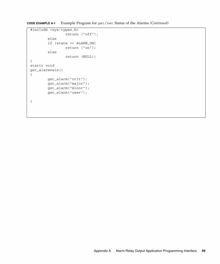
return ("off"); else if (state == ALARM_ON) return ("on"); else return (NULL);}static voidget_alarmvals(){ get_alarm("crit"); get_alarm("major"); get_alarm("minor"); get_alarm("user");
}
CODE EXAMPLE A-1 Example Program for get/set Status of the Alarms (Continued)
#include <sys/types.h>
Appendix A Alarm Relay Output Application Programming Interface 49

50 Netra 240 Server System Administration Guide • December 2005

Index
AAdvanced Lights Out Manager
see ALOMalarm
get status, 45 to 49relay output API, 45 to 49set status, 45 to 49
alarm boardalarm indicators, 6alarm states, 6
alarm indicators, 6critical, 6major, 7minor, 7user, 7
alarm states, dry contact, 6ALOM
Automatic Server Restart, 41basic functions, 39diagnostic tool, 2environmental monitoring subsystem, 41LED status indicators, 4overview, 37ports, 38setting password, 39
ASR, 29auto-boot? variable, 9Automatic Server Restart, 41Automatic System Recovery see also ASR, 29
BBIST, See built-in self-test
built-in self-test, test-args variable, 16
Ccentral processing unit, See CPUclock speed, CPU, 24CPU
clock speed, 24display information, 24
critical, alarm indicator, 6
Ddevice paths, hardware, 13, 16device tree, Solaris software, display, 19diag-level variable, 9, 15diagnostic tests, bypassing, 9diagnostic tool
ALOM, 2LEDs, 2OpenBoot command, 2OpenBoot diagnostics, 2Power-on Self-Test, 2Solaris software command, 2SunVTS, 2
diagnosticsOpenBoot, 14POST, 8Solaris OS, 18SunVTS, 33
diag-script variable, 9diag-switch? variable, 8, 9
51

Eenvironmental monitoring subsystem, 41error messages
log file, 42OpenBoot diagnostics tests, 17OpenBoot diagnostics, interpreting, 17power-related, 43
FFRU, 23 to 24
Hhardware device paths, 13, 16hardware revision, display showrev, 25host adapter (probe-scsi), 12
II2C bus, 42I2C sensors, 42IDE bus, 12input-device variable, 9integrated drive electronics (IDE), See IDE bus
LLEDs, diagnostic tool, 2locator LED, 4
off, 5on, 5status, 5
log files, 18error messages, 18system messages, 18
logical unit number (probe-scsi), 12loop ID (probe-scsi), 12
Mmajor, alarm indicator, 7message
interpreting errors, 17POST, error, 8
minor, alarm indicator, 7monitoring subsystem
over-temperature, 42under-temperature, 42
Nnormally closed (NC), relay state, 7normally open (NO), relay state, 7
Oobdiag-trigger variable, 9OpenBoot commands
diagnostic tool, 2probe-ide, 12probe-scsi and probe-scsi-all, 11run, 14show-devs, 13
OpenBoot configuration variablesdescription, 9keywords, 9
OpenBoot diagnostics, 14controlling tests, 15diagnostic tool, 2start, 14
OpenBoot diagnostics testsat ok prompt, 16error messages, interpreting, 17hardware device paths, 16test command, 16test-all command, 17
OpenBoot PROM parameters, diag-level variable, 8
output-device variable, 10over-temperature condition, 22over-temperature, monitoring subsystem, 42
Ppatches, installed, showrev, 25POST
diagnostic tool, 2diagnostics, controlling, 8error messages, 8start diagnostics, 10
post-trigger variable, 9power supplies, fault monitoring, 43Power-on self-test
see POSTprobe-ide command (OpenBoot), 12probe-scsi and probe-scsi-all commands
(OpenBoot), 11processor speed, display, 24
52 Netra 240 Server System Administration Guide • December 2005

prtconf command, Solaris, 19prtdiag command, Solaris, 21prtfru command,Solaris, 23psrinfo command, Solaris, 24
Rrelay state
normally closed (NC), 7normally open (NO), 7
reset events, kinds of, 9revision, hardware and software, display
showrev, 25
SSCSI devices, diagnosing problems, 11SEAM, 35server prompt
Advanced Lights Out Manager prompt, 3OpenBoot prompt, 3Solaris software superuser prompt, 3
server status indicators, front and rear, 4service required LED, 42show-devs command, OpenBoot, 13showrev command, Solaris, 25software revision, display showrev, 25Solaris commands
diagnostic tool, 2prtconf, 19prtdiag, 21prtfru, 23psrinfo, 24showrev, 25
Solaris OSdevice tree, 19SunVTS, 34
Sun Enterprise Authentication Mechanism see SEAM
Sun Validation Test Suitesee SunVTS
SunVTS, 33 to 36basic security, 35compatible version, 33, 36determine installation, 35diagnostic tool, 2documentation, 36installing, 36
interfaces, 33optional software packages, 34overview, 33SEAM security, 35software, test modes, 33Solaris OS, 34tests available, 34
system configuration card, 8system memory, determining size, 19system status LEDs
environmental fault indicators, 43See also LEDs
Ttemperature sensors, 42test command (OpenBoot diagnostics tests), 16test-all command (OpenBoot diagnostics
tests), 17test-args variable, 16
customize tests, 15keywords, 16
troubleshooting tools, 2
Uunder-temperature, monitoring subsystem, 42USB devices, OpenBoot diagnostics self-tests, 17user, alarm indicator, 7
Wwatch-net, 28World Wide Name (probe-scsi), 12
Index 53

54 Netra 240 Server System Administration Guide • December 2005