Embed Size (px)
Citation preview
Sun Microsystems, Inc.901 San Antonio RoadPalo Alto, CA 94303U.S.A. 650-960-1300
Send comments about this document to: [email protected]
Netra™ X1 Server User’s Guide
Part No. 806-5980-10December 2000

PleaseRecycle
Copyright 2000 Sun Microsystems, Inc., 901 San Antonio Road, Palo Alto, CA 94303-4900 U.S.A. All rights reserved.
This product or document is distributed under licenses restricting its use, copying, distribution, and decompilation. No part of this product or
document may be reproduced in any form by any means without prior written authorization of Sun and its licensors, if any. Third-party
software, including font technology, is copyrighted and licensed from Sun suppliers.
Parts of the product may be derived from Berkeley BSD systems, licensed from the University of California. UNIX is a registered trademark in
the U.S. and other countries, exclusively licensed through X/Open Company, Ltd.
Sun, Sun Microsystems, the Sun logo, AnswerBook2, docs.sun.com, UltraSPARC™-IIe, OpenBoot™ PROM, SunSolve, Solaris, and Netra are
trademarks, registered trademarks, or service marks of Sun Microsystems, Inc. in the U.S. and other countries. All SPARC trademarks are used
under license and are trademarks or registered trademarks of SPARC International, Inc. in the U.S. and other countries. Products bearing
SPARC trademarks are based upon an architecture developed by Sun Microsystems, Inc.
The OPEN LOOK and Sun™ Graphical User Interface was developed by Sun Microsystems, Inc. for its users and licensees. Sun acknowledges
the pioneering efforts of Xerox in researching and developing the concept of visual or graphical user interfaces for the computer industry. Sun
holds a non-exclusive license from Xerox to the Xerox Graphical User Interface, which license also covers Sun’s licensees who implement OPEN
LOOK GUIs and otherwise comply with Sun’s written license agreements.
Federal Acquisitions: Commercial Software—Government Users Subject to Standard License Terms and Conditions.
DOCUMENTATION IS PROVIDED “AS IS” AND ALL EXPRESS OR IMPLIED CONDITIONS, REPRESENTATIONS AND WARRANTIES,
INCLUDING ANY IMPLIED WARRANTY OF MERCHANTABILITY, FITNESS FOR A PARTICULAR PURPOSE OR NON-INFRINGEMENT,
ARE DISCLAIMED, EXCEPT TO THE EXTENT THAT SUCH DISCLAIMERS ARE HELD TO BE LEGALLY INVALID.
Copyright 2000 Sun Microsystems, Inc., 901 San Antonio Road, Palo Alto, CA 94303-4900 Etats-Unis. Tous droits réservés.
Ce produit ou document est distribué avec des licences qui en restreignent l’utilisation, la copie, la distribution, et la décompilation. Aucune
partie de ce produit ou document ne peut être reproduite sous aucune forme, par quelque moyen que ce soit, sans l’autorisation préalable et
écrite de Sun et de ses bailleurs de licence, s’il y en a. Le logiciel détenu par des tiers, et qui comprend la technologie relative aux polices de
caractères, est protégé par un copyright et licencié par des fournisseurs de Sun.
Des parties de ce produit pourront être dérivées des systèmes Berkeley BSD licenciés par l’Université de Californie. UNIX est une marque
déposée aux Etats-Unis et dans d’autres pays et licenciée exclusivement par X/Open Company, Ltd.
Sun, Sun Microsystems, le logo Sun, AnswerBook2, docs.sun.com, UltraSPARC™-IIe, OpenBoot™ PROM, Solaris et Netra sont des marques de
fabrique ou des marques déposées, ou marques de service, de Sun Microsystems, Inc. aux Etats-Unis et dans d’autres pays. Toutes les marques
SPARC sont utilisées sous licence et sont des marques de fabrique ou des marques déposées de SPARC International, Inc. aux Etats-Unis et dans
d’autres pays. Les produits portant les marques SPARC sont basés sur une architecture développée par Sun Microsystems, Inc.
L’interface d’utilisation graphique OPEN LOOK et Sun™ a été développée par Sun Microsystems, Inc. pour ses utilisateurs et licenciés. Sun
reconnaît les efforts de pionniers de Xerox pour la recherche et le développement du concept des interfaces d’utilisation visuelle ou graphique
pour l’industrie de l’informatique. Sun détient une licence non exclusive de Xerox sur l’interface d’utilisation graphique Xerox, cette licence
couvrant également les licenciés de Sun qui mettent en place l’interface d’utilisation graphique OPEN LOOK et qui en outre se conforment aux
licences écrites de Sun.
LA DOCUMENTATION EST FOURNIE “EN L’ETAT” ET TOUTES AUTRES CONDITIONS, DECLARATIONS ET GARANTIES EXPRESSES
OU TACITES SONT FORMELLEMENT EXCLUES, DANS LA MESURE AUTORISEE PAR LA LOI APPLICABLE, Y COMPRIS NOTAMMENT
TOUTE GARANTIE IMPLICITE RELATIVE A LA QUALITE MARCHANDE, A L’APTITUDE A UNE UTILISATION PARTICULIERE OU A
L’ABSENCE DE CONTREFAÇON.
Contents
Part I. Installation and Configuration
1. Introducing the Netra X1 Server 1
Overview of the Netra X1 Server 2
Physical Specifications 3
Contents of the Ship Kit 3
Optional Components 4
Environmental Specifications 4
Acoustic Noise Generated 5
Environmental Compliance Information 5
Choosing Between a Rack and a Cabinet 5
2. Operating Power and Cooling 7
Operating Power Statistics 8
Calculating Power Consumption 9
Calculating Heat Dissipation 9
3. Installing the Netra X1 Server Into a Rack 11
Installing the Server Into a Standard19-inch Rack 12
Using Alternative Bracket Arrangements 13
Contents iii
4. Connecting the Cables 15
Connecting the Cables to the Server 16
Setting Up Serial Connections 18
Using a DB-25 Adapter for the Serial Link 20
Using a DB-9 Adapter for the Serial Link 21
Serial Connection Settings 22
5. Powering On the Netra X1 Server 23
Preparing to Configure the Server 24
Powering On the Server for the First Time 25
Using the Power (On/Standby) Switch 30
Part II. Remote and Local Management
6. Managing the Netra X1 Server From the lom> Prompt 35
Introduction to Lights-Out Management 36
Powering On or Resetting the Server From the LOMlite2 Shell 36
Controlling the Server’s Booting Behavior 40
Monitoring the Server From the LOMlite2 Shell 41
Viewing the LOMlite2 Event Log 43
Verifying That a Component Has Been Fixed 45
Setting Up LOMlite2 Privileges for Named Users 46
Permissions Available for LOMlite2 Users 46
Setting the LOMlite2 Device’s Configurable Variables 50
Separating LOMlite2 From the Console on the Serial A/LOM Port 52
Viewing Event Reports That LOMlite2 Sends to syslogd 53
LOMlite2 Shell Command List 54
Checking the Fans 56
7. Managing the Netra X1 Server From the Solaris Prompt 57
Contents iv

Monitoring the System From the Solaris Prompt 58
Checking the Supply Rail Voltages and Internal Circuit Breakers (lom -v ) 59
Configuring LOMlite2 to Restart the Server Automatically After a Lockup 64
Enabling the LOMlite2 Watchdog Process From Your Own Script or
Command (lom -W on ) 65
Other LOM Tasks You Can Perform From the Solaris Prompt 67
Part III. Troubleshooting and Maintenance
8. Troubleshooting 73
Solutions to Problems You Might Encounter 74
9. Interpreting the LEDs 77
Interpreting the Front- and Back-Panel LEDs 78
Front-Panel LEDs 78
Back-Panel LEDs 79
10. Removing and Replacing Components 81
Replacing an Entire Netra X1 Server 82
Altering a Netra X1 Server 83
Identifying Components 87
Memory Installation and Removal 88
Hard Disk Drive (HDD) Installation and Removal 89
Part IV. Appendix
Contents v

vi Netra X1 Server User’s Guide • December 2000

Figures
FIGURE 1-1 The Netra X1 Server 2
FIGURE 3-1 Mounting the Server in a Standard 19-inch Rack 12
FIGURE 3-2 Forward Facing Rackmounting Brackets 13
FIGURE 3-3 Rear Facing Rackmounting Brackets 13
FIGURE 3-4 Alternative Rackmounting Position 14
FIGURE 4-1 The Server’s Back Panel 16
FIGURE 4-2 Connecting Cables to the Netra X1 Server 17
FIGURE 4-3 Patch Panel Connection Between a Cisco L2511 Server and a Netra X1 Server 19
FIGURE 4-4 Serial Port Pins 1 to 8 20
FIGURE 5-1 Netra X1 Server Power (On/Standby) Switch 30
FIGURE 7-1 Sample LOMlite2 Device Event Log (Oldest Event Reported First) 63
FIGURE 9-1 Front-Panel Power and Fault LEDs 78
FIGURE 9-2 Back-Panel Power and Fault LEDs 80
FIGURE 10-1 The System Configuration Card Reader 83
FIGURE 10-2 Using the Disposable Antistatic Wrist Strap Supplied With the System 84
FIGURE 10-3 Removing the Top Cover 85
FIGURE 10-4 Replacing the Top Cover 86
FIGURE 10-5 Layout of Components 87
FIGURE 10-6 DIMM Insertion Order 88
Figures vii

FIGURE 10-7 Installing Memory Into a Socket on the System Board 89
FIGURE 10-8 Removing the HDD Placeholder 90
FIGURE 10-9 Installing a Hard Disk Drive 91
FIGURE 10-10 Attaching the Power and Data Cables 91
viii Netra X1 Server User’s Guide • December 2000

Tables
TABLE 1-1 Physical Specifications 3
TABLE 1-2 Contents of the Ship Kit 3
TABLE 1-3 Customer Installable Hardware 4
TABLE 1-4 Environmental Specifications 4
TABLE 2-1 Operating Power Statistics 8
TABLE 2-2 Estimated Power Consumption of the Netra X1 Server Components 9
TABLE 4-1 Pin Crossovers for Connecting to a Typical Terminal Server 20
TABLE 4-2 Pin Crossovers in the Sun DB-25 (25-Pin) Adapter 21
TABLE 4-3 Pin Crossovers for a DB-9 (9-Pin) Adapter 21
TABLE 4-4 Settings for Connecting to the Serial A/LOM or Serial B Port 22
TABLE 6-1 Boot Modes 40
TABLE 6-2 LOM Commands 54
Tables ix

x Netra X1 Server User’s Guide • December 2000

Preface
The Netra X1 Server User’s Guide describes how to install, manage, and maintain the
Netra™ X1 server. The manual is intended for system administrators who have
experience in setting up networked SolarisTM servers.
How This Book Is Organized
Part I Installation and Configuration
Chapter 1 introduces the Netra X1 server, provides an overview of the system and
includes information on physical operating conditions and rackmounting
implications.
Chapter 2 provides information about the power and cooling requirements for the
Netra X1 server.
Chapter 3 provides instructions on installing the Netra X1 server into a standard 19-
inch rack and describes the various bracket-mounting options that are available.
Chapter 4 specifies how to attach the cables and power source to the Netra X1 server
and how to set up serial connections to it.
Chapter 5 explains how to perform the initial power-on and configuration of the
server.
Part II Netra X1 Remote and Local Management
Chapter 6 explains how to use the LOMlite2 shell.
Chapter 7 describes how to use LOMlite2-specific Solaris commands to monitor and
manage the system. This chapter also explains how to configure LOMlite2 to restart
the server in the event of a system lockup.
xi

Part III Troubleshooting and Maintenance
Chapter 8 summarizes some possible problems with setting up the server and
explains how to overcome them.
Chapter 9 provides information about the fault and power indicators and explains
how to identify a faulty system in a rack.
Chapter 10 describes how to swap system configuration cards and how to open the
Netra X1 server to add memory or a hard disk drive.
Part IV Appendix
Appendix A describes the parameters you can configure in the LOMlite2 driver
configuration file.
Using UNIX Commands
This document may not contain information on basic UNIX® commands and
procedures such as shutting down the system, booting the system, and configuring
devices.
See one or more of the following for this information:
■ Solaris Handbook for Sun Peripherals
■ AnswerBook2™ online documentation for the Solaris software environment
■ Other software documentation that you received with your system
xii Netra X1 Server User’s Guide • December 2000

Typographic Conventions
Shell Prompts
Typeface Meaning Examples
AaBbCc123 The names of commands, files,
and directories; on-screen
computer output
Edit your .login file.
Use ls -a to list all files.
% You have mail .
AaBbCc123 What you type, when
contrasted with on-screen
computer output
% suPassword:
AaBbCc123 Book titles, new words or
terms, words to be emphasized
Command-line variable;
replace with a real name or
value
Read Chapter 6 in the User’s Guide.
These are called class options.
You must be superuser to do this.
To delete a file, type rm filename.
Shell Prompt
C shell machine_name%
C shell superuser machine_name#
Bourne shell and Korn shell $
Bourne shell and Korn shell superuser #
LOM shell lom>
OBP ok>
Preface xiii

Sun Welcomes Your Comments
We are interested in improving our documentation and welcome your comments
and suggestions. You can email your comments to us at:
Please include the part number (806-5980-10) of your document in the subject line of
your email.
Safety Precautions
For your protection, observe the following safety precautions when setting up your
equipment:
■ Follow all cautions and instructions marked on the equipment.
■ Never push objects of any kind through openings in the equipment. Dangerous
voltages may be present. Conductive foreign objects can produce a short circuit
that could cause fire, electric shock, or damage to your equipment.
Symbols
The following symbols may appear in this manual:
Caution – There is a risk of personal injury and equipment damage. Follow the
instructions.
Caution – Hazardous voltages are present. To reduce the risk of electric shock and
danger to personal health, follow the instructions.
xiv Netra X1 Server User’s Guide • December 2000

Modifications to Equipment
Do not make mechanical or electrical modifications to the equipment. Sun
Microsystems is not responsible for the regulatory compliance of a modified
product.
Caution – Do not block or cover the openings of your Sun product. Never place a
Sun product near a radiator or heat register. Failure to follow these guidelines can
cause overheating and affect the reliability of your Sun product.
Caution – If your Netra X1 server is installed in a closed or multi-unit rack
assembly, the operating ambient temperature of the rack environment may exceed
the room ambient temperature. Ensure that rack environment ambient temperature
does not exceed 40 degrees.
Caution – Mounting of the equipment in a rack or cabinet should be such that a
hazardous condition is not created due to uneven mechanical loading or weight
distribution.
Caution – Ensure that the connection of multiple system units to the circuit does
not overload the supply overcurrent protection or supply wiring. Consider the Sun
agency label electrical ratings when determining the correct branch circuit rating for
your installation.
Caution – All supply connections, wiring, wire protection, and wire routing must
be made in accordance with applicable sections and requirements of national
electrical code and local electrical authorities.
Preface xv

xvi Netra X1 Server User’s Guide • December 2000
PART I Installation and Configuration


CHAPTER 1
Introducing the Netra X1 Server
This chapter gives an overview of the NetraX1 server. It lists the features of the
server and the contents of the ship kit, and describes the server’s tolerance of, or
suitability for, various environmental conditions. Finally, the chapter offers some
guidance to help you decide whether to mount the system in a rack or a cabinet.
The chapter contains the following sections:
■ “Overview of the Netra X1 Server” on page 2
■ “Contents of the Ship Kit” on page 3
■ “Optional Components” on page 4
■ “Environmental Specifications” on page 4
■ “Choosing Between a Rack and a Cabinet” on page 5
1

Overview of the Netra X1 Server
The Netra X1 server is a single-processor, thin (1U) server designed primarily for use
by telecommunications carriers and internet service providers. It is also suitable for
use within corporate customer networks, wherever there is a need to maximize the
density of high-performance Solaris servers.
FIGURE 1-1 The Netra X1 Server
The server has the following features:
■ Single UltraSPARC™-IIe 400 MHz processor
■ Rackmounting enclosure with single power supply
■ Four DIMM sockets accepting standard 128- or 256-Mbyte PC133 memory
modules (giving a maximum of 1 Gbyte of memory)
■ Two 10/100 Mbps RJ-45 Ethernet ports
■ Console/Lights Out Management RJ-45 serial port
■ Second RJ-45 serial port
■ Two USB ports
■ Support for up to two low-profile, 3.5-inch IDE disks
2 Netra X1 Server User’s Guide • December 2000
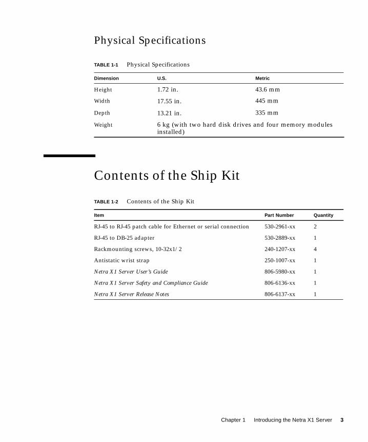
Physical Specifications
Contents of the Ship Kit
TABLE 1-1 Physical Specifications
Dimension U.S. Metric
Height 1.72 in. 43.6 mm
Width 17.55 in. 445 mm
Depth 13.21 in. 335 mm
Weight 6 kg (with two hard disk drives and four memory modulesinstalled)
TABLE 1-2 Contents of the Ship Kit
Item Part Number Quantity
RJ-45 to RJ-45 patch cable for Ethernet or serial connection 530-2961-xx 2
RJ-45 to DB-25 adapter 530-2889-xx 1
Rackmounting screws, 10-32x1/2 240-1207-xx 4
Antistatic wrist strap 250-1007-xx 1
Netra X1 Server User’s Guide 806-5980-xx 1
Netra X1 Server Safety and Compliance Guide 806-6136-xx 1
Netra X1 Server Release Notes 806-6137-xx 1
Chapter 1 Introducing the Netra X1 Server 3

Optional Components
Sun offers additional hard disk drives and memory modules for the server. To order
them, contact your local Sun sales representative. See TABLE 1-3 for a list of
components and part numbers. The server itself was designed as a replaceable unit
which means that, if a fault occurs, you should contact your local Sun sales
representative for a replacement
Environmental Specifications
You can operate and store the system safely in the following conditions:
TABLE 1-3 Customer Installable Hardware
Optional Components Part Number
128-Mbyte DIMM X7090A
256-Mbyte DIMM X7091A
20 Gbyte, 5400 rpm hard disk drive X7095A
TABLE 1-4 Environmental Specifications
Specifications Operating Storage
Ambient temperature 5˚C to 40˚C
14˚F to 104˚F
–40˚C to 70˚C–8˚F to 158˚F
Temperature variation 30˚C/hr maximum86˚F/hr maximum
30˚C/hr maximum86˚F/hr maximum
Relative humidity 5% to 85%
(noncondensing)
10% to 95%(noncondensing)
Altitude –300m to +3000m –300m to +12000m
4 Netra X1 Server User’s Guide • December 2000

Acoustic Noise Generated
The system generates less than 60 dBA at a distance of 23.67 inches (600 mm) and a
height of 59.17 inches (1500 mm) while operating irn an ambient temperature of 77˚F
(25˚C).
Environmental Compliance Information■ Electromagnetic compatibility
■ Immunity: The server conforms to EN55024.
■ Emissions: The server conforms to EN55022 Class A and FCC Class A.
■ Safety
The system conforms to UL 1950 (3rd edition), EN60950
Choosing Between a Rack and a Cabinet
A Netra X1 server can be installed in either a rack or a cabinet. Factors that might
influence your decision include:
■ SecurityIf other people have access to the room in which your servers are located, you can
increase security by locking the servers in a cabinet.
■ Thermal issuesCabinets often require additional fans, because the systems installed in them
generate heat in an enclosed space. Two-post racks, however, may require no
special cooling systems.
■ FlooringTwo-post telco relay racks are designed so that cables can be run overhead.
Cabinets often require cables to be run under the floor.
Chapter 1 Introducing the Netra X1 Server 5

6 Netra X1 Server User’s Guide • December 2000

CHAPTER 2
Operating Power and Cooling
This chapter describes the power consumption and heat generation characteristics of
the Netra X1 server. It contains the following sections:
■ “Operating Power Statistics” on page 8
■ “Calculating Power Consumption” on page 9
■ “Calculating Heat Dissipation” on page 9
7

Operating Power Statistics
* The in-rush current decays to the normal operating current in less than 200 msecs.
** This BTU assumes a system fully loaded with hardware option modules (see “Calculating
Heat Dissipation” on page 9).
Caution – The power supply continues to regulate all outputs for at least 17 ms
after AC power is removed.
Note – Logic ground and chassis ground are connected internally.
Note – Power from the standby output is available whenever input power is
connected.
TABLE 2-1 Operating Power Statistics
Maximum operating current 3A @ 115 VAC
Typical operating current See “Calculating Power Consumption” on
page 9
Maximum in-rush
current (cold start)
40A peak at 115V 25˚C
Maximum in-rush
current (warm start, or upon a restart 20 to
200 msecs after power has been removed*)
100A peak at 115V 25˚C
Operating input voltage range 90 to 264 Vrms
Voltage frequency range 47 to 63 Hz
Power factor 0.9 to 0.99
Maximum
volt-ampere rating
150 VA
BTU rating 493.6 BTU**
8 Netra X1 Server User’s Guide • December 2000

Calculating Power Consumption
A Netra X1 server containing two disk drives has an estimated current requirement
of approximately 1 amp.
TABLE 2-2 shows the estimated power consumed by the individual components in a
fully powered system. However, when you are calculating the power requirements
for your system, you must allow for 63 percent PSU efficiency. To perform this
calculation, add the figures (from the third column of TABLE 2-2) for each component
installed in the system, then divide the result by 0.63.
Note – To calculate the total power requirement for several servers installed in a
single rack or cabinet, you add the individual power requirement figure (TABLE 2-2)
for each server installed.
Calculating Heat Dissipation
To calculate the heat generated by a server so that you can estimate the heat your
cooling system must dissipate, convert the figure for the system’s power
requirement from watts to BTU/hr. A general formula for doing this is to multiply
the figure for the power requirement by 3.415.
TABLE 2-2 Estimated Power Consumption of the Netra X1 Server Components
Component Measurement Estimated Power Consumption
Base system 400 MHz 20.0W
Memory per DIMM 4.59W (256 Mbytes, burst mode)
Disk drive 20 Gbyte/5400 rpm 6.5W (idle)
Chapter 2 Operating Power and Cooling 9

10 Netra X1 Server User’s Guide • December 2000
CHAPTER 3
Installing the Netra X1 Server Into aRack
This chapter explains how to install the Netra X1 server into a standard 19-inch rack
and describes the various mounting options available. This information is given in
the following sections:
■ “Installing the Server Into a Standard 19-inch Rack” on page 12
■ “Using Alternative Bracket Arrangements” on page 13
11

Installing the Server Into a Standard19-inch Rack
The Netra X1 server fits a standard 19-inch rack. There are five mounting points for
the brackets on each side of the server, allowing a choice of mounting positions. The
standard position uses the forward three mounting points on the server (see
FIGURE 3-2).
You can adjust the position of the server in the rack by using a different set of
mounting points for the brackets (see FIGURE 3-4).
▼ To Mount the Server in a 19-inch Rack
1. Position the Netra X1 server in the rack and tighten the screws (see FIGURE 3-1).
2. Attach the cables (see Chapter 4).
FIGURE 3-1 Mounting the Server in a Standard 19-inch Rack
12 Netra X1 Server User’s Guide • December 2000

Using Alternative Bracket Arrangements
The server can be mounted in various positions in a rack by changing the position of
the rackmounting brackets on the server. The brackets be attached to any three of the
mounting points on the side of the server, facing either to the front (see FIGURE 3-2)
or to the rear of the server (see FIGURE 3-3).
FIGURE 3-2 Forward Facing Rackmounting Brackets
FIGURE 3-3 Rear Facing Rackmounting Brackets
Chapter 3 Installing the Netra X1 Server Into a Rack 13

▼ To Use Alternative Bracket Arrangements
1. Choose the configuration that best suits your installation.
2. Reposition the rackmounting brackets on the side of the server.
3. Position the server in the rack and tighten the screws.
FIGURE 3-4 Alternative Rackmounting Position
4. Attach the cables (see Chapter 4).
14 Netra X1 Server User’s Guide • December 2000

CHAPTER 4
Connecting the Cables
This chapter provides information on connecting the Ethernet, serial, and power
cables to a Netra X1 server. It also describes the types of serial connection that you
can make to the server. The chapter contains the following sections:
■ “Connecting the Cables to the Server” on page 16
■ “Setting Up Serial Connections” on page 18
15

Connecting the Cables to the Server
Before following the instructions in this section, make sure you have installed the
server into a rack or cabinet (see Chapter 3).
The server’s ports are arranged and numbered as in FIGURE 4-1.
FIGURE 4-1 The Server’s Back Panel
▼ To Connect the Cables to the Server
1. Connect the power cord.
2. Connect at least one serial device.
For more information, see “Setting Up Serial Connections” on page 18.
If you want to use the server’s remote monitoring and management facilities, make
sure you use the port labeled Serial A/LOM.
3. Connect the server to at least one Ethernet hub.
You can connect to a maximum of two Ethernet hubs.
4. Connect the server to a maximum of two USB devices.
On/Standby
System configurationcard reader
Serial B
Ethernet 1
USB 0
Power
Serial A/LOM USB 1
FanEthernet 0
16 Netra X1 Server User’s Guide • December 2000

5. If you intend to configure the server directly from a dumb terminal or a Sunworkstation, insert the serial cable into the DB-25 adapter that was packaged withyour server.
When you have done this, connect the adapter to the DB-25 serial connector on the
terminal or on the Sun workstation.
Refer to Chapter 5 for information about powering on the system.
Refer to Chapter 8 for information about any software patches you might need to
apply.
FIGURE 4-2 Connecting Cables to the Netra X1 Server
Caution – AC-powered Sun products are designed to work with single-phase
power systems that have a grounded neutral conductor. To reduce the risk of electric
shock, do not connect Sun products to any other type of power system. Contact your
facilities manager or a qualified electrician if you are not sure what type of power is
supplied to your building.
Caution – Your AC-powered Sun product is packaged with a grounding type
(three-wire) power cord. To reduce the risk of electric shock, always connect the cord
to a grounded outlet.
Seriallinks
Ethernetlinks
AC powercable
USBlinks
Chapter 4 Connecting the Cables 17

Setting Up Serial Connections
To perform the initial configuration when you install the Netra X1 server, and also
for ongoing monitoring and management of the system, you will need to use at least
one of the serial ports on the system’s back panel. You can connect either or both
serial ports to any of the following devices:
■ A Sun workstation or dumb terminalFor this connection you can use the standard RJ-45 patch cable supplied with the
server, but you need to insert one end into the DB-25 adapter also supplied.
■ A terminal server (or patch panel connected to a terminal server)The pinouts for the server’s serial ports correspond with the pinouts for the RJ-45
ports on the Asynchronous Serial Interface Breakout Cable supplied by Cisco for
use with the Cisco L2511 terminal server. For terminals from other manufacturers,
you may need to make your own crossover (null-modem) cable (see “To Connect
to a Terminal Server” on page 18).
■ A modemFor this connection you can use the standard RJ-45 patch cable supplied with the
server, but you need to insert one end into the DB-25 adapter which is also
supplied with the server. Do not use the Serial A/LOM port for binary data
transfers. To perform any task other than an ASCII transfer, use the port labeled
Serial B.
▼ To Connect to a Terminal Server
The serial ports on the Netra X1 server are DTE ports. If you connect these to other
DTE ports, then the cabling between them must perform a crossover.
The pinouts for the server’s serial ports correspond with the pinouts for the RJ-45
ports on Cisco terminal servers. This means that if you are using a Cisco L2511
Terminal Server (and you are connecting the Netra X1 server to it using the Cisco
Asynchronous Serial Interface Breakout Cable), you have two connection options:
■ Connect the breakout cable directly to the Netra X1 server.
■ Connect the breakout cable to a patch panel and use the straight-through patch
cable (supplied by Sun) to connect the patch panel to the server (see FIGURE 4-3).
18 Netra X1 Server User’s Guide • December 2000

Note – You do not have to use the Netra X1 server with a Cisco terminal server. For
other terminal servers, check the manufacturer’s documentation to see if the pinouts
of the serial ports on the terminal server match the pinouts of the Netra X1 server’s
serial ports. If they do not, you need to make a cable that takes each pin on one of
the Netra X1 server’s serial ports to the corresponding pin in the terminal server’s
serial port.
FIGURE 4-3 Patch Panel Connection Between a Cisco L2511 Server and a Netra X1 Server
Cisco L2511server
Asynchronousbreakoutcable
Patch panel
Chapter 4 Connecting the Cables 19

Note – When viewed from the back of the server, the pin arrangement of the RJ-45
ports is as shown below.
FIGURE 4-4 Serial Port Pins 1 to 8
Using a DB-25 Adapter for the Serial Link
The pinouts are identical for the RJ-45 serial ports on the Netra X1 server. To connect
to a Solaris tip session or to a vt100 terminal, you need to use either the DB-25 (25-
Pin DSUB Male to 8-POS RJ-45 Female) adapter that is supplied by Sun (part no.
530-2889) with your system, or an alternative adapter that performs the same pin
crossovers. The Sun-supplied DB-25 adapter enables you to connect to any Sun
system. The crossovers it performs are listed in TABLE 4-2.
TABLE 4-1 Pin Crossovers for Connecting to a Typical Terminal Server
Netra X1 Serial Port (RJ-45 Connector) Pin Terminal Server Serial Port Pin
Pin 1 (RTS) Pin 1 (CTS)
Pin 2 (DTR) Pin 2 (DSR)
Pin 3 (TXD) Pin 3 (RXD)
Pin 4 (Signal Ground) Pin 4 (Signal Ground)
Pin 5 (Signal Ground) Pin 5 (Signal Ground)
Pin 6 (RXD) Pin 6 (TXD)
Pin 7 (DSR) Pin 7 (DTR)
Pin 8 (CTS) Pin 8 (RTS)
18
1 8
Serial Port A
Serial Port B
20 Netra X1 Server User’s Guide • December 2000

Note – If you need to set up a modem connection to the Netra X1 server, you must
use the port labeled Serial B. The Serial A/LOM port does not assert the required
constant DTR signal.
Using a DB-9 Adapter for the Serial Link
To connect to a terminal that has a 9-pin serial connector, connect one of the Netra
X1 server’s serial ports to a DB-9 (9-pin) adapter that performs the pin crossovers
listed in TABLE 4-3.
TABLE 4-2 Pin Crossovers in the Sun DB-25 (25-Pin) Adapter
Serial Port (RJ-45 Connector) Pin 25-Pin Connecter
Pin 1 (RTS) Pin 5 (CTS)
Pin 2 (DTR) Pin 6 (DSR)
Pin 3 (TXD) Pin 3 (RXD)
Pin 4 (Signal Ground) Pin 7 (Signal Ground)
Pin 5 (Signal Ground) Pin 7 (Signal Ground)
Pin 6 (RXD) Pin 2 (TXD)
Pin 7 (DSR) Pin 20 (DTR)
Pin 8 (CTS) Pin 4 (RTS)
TABLE 4-3 Pin Crossovers for a DB-9 (9-Pin) Adapter
Serial Port (RJ-45 Connector) Pin 9-Pin Connector
Pin 1 (RTS) Pin 8 (CTS)
Pin 2 (DTR) Pin 6 (DSR)
Pin 3 (TXD) Pin 2 (RXD)
Pin 4 (Signal Ground) Pin 5 (Signal Ground)
Pin 5 (Signal Ground) Pin 5 (Signal Ground)
Pin 6 (RXD) Pin 3 (TXD)
Pin 7 (DSR) Pin 4 (DTR)
Pin 8 (CTS) Pin 7 (RTS)
Chapter 4 Connecting the Cables 21

Serial Connection Settings
The settings you need to use for a serial connection are listed in TABLE 4-4. If you
need to perform binary data transfers (that is, transfers of anything more than
simple ASCII character streams), use the Serial B port. Communication on the Serial
A/LOM port is subject to interruption by the Lights Out Management (LOM) device
(see “Introduction to Lights-Out Management” on page 36).
TABLE 4-4 Settings for Connecting to the Serial A/LOM or Serial B Port
Parameter Setting
Connector Serial A/LOM or Serial B (use Serial B for binary data transfers)
Rate 9600 baud
Parity No
Stop bits 1
Data bits 8
22 Netra X1 Server User’s Guide • December 2000

CHAPTER 5
Powering On the Netra X1 Server
This chapter explains how to configure the server, power it on, and use the Power
(On/Standby) switch. The chapter contains the following sections:
■ “Preparing to Configure the Server” on page 24
■ “Powering On the Server for the First Time” on page 25
■ “Using the Power (On/Standby) Switch” on page 30
23

Preparing to Configure the Server
To perform the initial configuration of the Netra X1 server, set up a serial connection
via the port labeled Serial A/LOM on the server’s back panel (see Chapter 4). Make
sure you have the server’s power cord connected.
▼ To Configure Using a Terminal Server
● To access the Netra X1 server from a Sun workstation via a terminal server, open aterminal session on the Sun workstation, and type:
For example, for a Netra X1 server connected to port 10000 on a terminal server
whose IP address is 192.20.30.10, you would type:
▼ To Configure From a Terminal or Workstation
● To access the Netra X1 server from a dumb terminal, set up a connection betweenthe terminal and the Netra X1 server.
● To access the Netra X1 server from a Sun workstation directly connected to theserver, set up the connections between the devices, then run a terminal session bytyping:
The tip command above assumes that your console is using its ttya serial port. If
you later configure your console to use ttyb, you must type the following to set up a
tip session:
# telnet IP-address-of-terminal-server port-number
# telnet 192.20.30.10 10000
# tip /dev/term/a -9600
# tip /dev/term/b -9600
24 Netra X1 Server User’s Guide • December 2000

For information about dedicating the console to Serial B, see “Managing the Netra
X1 Server From the lom> Prompt” on page 35).
Powering On the Server for the FirstTime
When the Netra X1 server is connected to mains electricity, it is always either fully
powered or in standby power mode. To completely remove power from a server,
you must disconnect its power cable. The methods referred to in this section and the
next section power the server on, or return it to standby power mode. They cannot
be used to power the server off completely.
■ using lom> prompt commands
■ using the rocker switch on the server’s back panel.
For more information, see “Using the Power (On/Standby) Switch” on page 30.
▼ To Power On With the Server’s Details
Registered at a Name Server
Note – Follow the instructions in this section only if you have a name server
installed on your network. For instructions on using a name server to automate the
process of configuring the Solaris operating environment on multiple servers, refer
to the Solaris 8 Advanced Installation Guide which accompanies the Solaris 8 CDs.
1. Connect the server to the power supply but do not power it on.
2. Set up a serial connection to the Serial A/LOM port and also a connection to atleast one Ethernet hub (as described in Chapter 4).
Chapter 5 Powering On the Netra X1 Server 25

3. At the console lom> prompt, type the following command to power on the server:
For more information about the lom> prompt and the commands that are available
from it, see Chapter 6.
During booting you will be prompted for certain information. The first question the
system asks you is what language you want it to use when prompting you for the
rest of the information.
4. Specify a language.
5. Specify your locale.
6. Specify the type of terminal you are using to communicate with the Netra X1server.
7. Specify whether you need IPv6 enabled, and then follow the instructions on thescreen.
8. Specify whether you want to enable the Kerberos Security mechanism, and thenfollow the instructions on the screen.
9. Confirm the information you have typed.
10. Specify time and date information.
11. Give a password (if any) for users logging in as root.
12. When asked if you want the server to perform Automatic Power SavingShutdown, answer No.
Note – If you answer Yes, the server will automatically put itself into Standby mode
after a period of idleness.
When you have provided the information the system needs, it will boot.
▼ To Power On Without the Server’s Details
Registered at a Name Server
Follow the instructions in this section if you do not have a Name Server configured
on your network.
lom> poweron
26 Netra X1 Server User’s Guide • December 2000

Read these instructions through before you follow them, to find out the information
for which the system will prompt you when you start it for the first time.
1. Connect the server to the power supply but do not power it on.
2. Set up a serial connection to the Serial A/LOM port and also a connection to atleast one Ethernet hub (as described in Chapter 4).
3. At the lom> prompt, type the following command to power on the server:
For more information about the lom> prompt and the commands that are available
from it, see Chapter 6.
During booting you will be prompted for certain information. The first question the
system asks you is what language you want it to use when it prompts you for the
information it needs.
4. Specify a language.
5. Specify your locale.
6. Specify the type of terminal you are using to communicate with the Netra X1server.
7. Specify whether the IP address is to be configured manually or by DHCP.
If manually, specify an IP address when prompted.
8. Specify which of the Ethernet ports you intend to use as the primary Ethernetconnection.
For the port labeled Net0, specify dmfe0 . For the port labeled Net1, specify dmfe1 .
9. Specify a host name for the server.
10. Specify whether you need IPv6 enabled, and then follow the instructions on thescreen.
11. Specify whether you want to enable the Kerberos Security mechanism, and thenfollow the instructions on the screen.
12. Specify the name service you want the server to use.
13. Specify the name of the domain of which the server will be a part.
14. Specify whether you want the system to search the network for a name server orwhether you want it to use a particular name server.
15. If you chose to use a particular name server, specify the host name and IP addressof the name server.
lom> poweron
Chapter 5 Powering On the Netra X1 Server 27

16. Specify whether the Netra X1 server is to be part of a subnet.
17. Specify a Netmask for the server.
18. Confirm the information you have typed.
19. Specify time and date information.
20. When prompted, give a password (if any) for users logging in as root.
21. When asked if you want the server to perform Automatic Power SavingShutdown, answer No.
Note – If you answer Yes, the server will automatically put itself into Standby mode
after a period of idleness.
When you have provided the information the system needs, it will boot.
▼ To Power On a Standalone Server for the First
Time
1. Connect the server to the power supply but do not power it on.
2. Set up a serial connection using the Serial A/LOM port (as described inChapter 6).
3. At the lom> prompt, type the following command to power on the server:
For more information about the lom> prompt and the commands that are available
from it, see Chapter 8.
4. Specify a language.
5. Specify your locale.
6. Specify the type of terminal you are using to communicate with the Netra X1server.
7. When prompted to indicate whether you want the server to be networked, specifyNo.
8. Specify a Host Name for the server.
9. Confirm the information you have given.
lom> poweron
28 Netra X1 Server User’s Guide • December 2000

10. Specify the date and time information.
11. When prompted, give a password (if any) for users logging in as root.
12. When asked if you want the server to perform Automatic Power SavingShutdown, answer No.
Note – If you answer Yes, the server will automatically put itself into Standby mode
after a period of idleness.
The system will boot when you have provided it with the information it needs.
▼ To Clear Your Configuration and Start Again
If you want to start the power on process again, as if from a previously unused
server, you must clear the configuration of the server.
● If you are at the lom> prompt, go to the ok prompt by typing:
1. Boot the server into the Solaris environment by typing:
2. At the Solaris prompt, type:
3. When prompted to confirm that you want to create a ‘blank’ server, type y.
4. When the server has unconfigured itself, type the LOM escape sequence. Bydefault, this is:
When the lom> prompt appears, follow the instructions in either of the following
sections:
lom> break
ok boot
# sys-unconfig
# #.
Chapter 5 Powering On the Netra X1 Server 29

■ “To Power On With the Server’s Details Registered at a Name Server” on page 25
or
■ “To Power On Without the Server’s Details Registered at a Name Server” on
page 26.
Using the Power (On/Standby) Switch
Caution – The power switch (on the back panel of the Netra X1 server) is not an
On/Off switch, it is an On/Standby switch. It does not isolate the equipment.
The power (On/Standby) switch of the Netra t1 server is a rocker type, momentary
action switch. It controls only low-voltage signals; no high-voltage circuits pass
through it. This means that the main method of connecting or disconnecting power
is by inserting or removing the power supply cord. The server contains no integral
circuit breakers. To isolate it, you must break all connections to it. If you do not do
this by removing the power supply cord, you must instead open all external circuit
breakers.
FIGURE 5-1 Netra X1 Server Power (On/Standby) Switch
The symbols on the switch are:
On
■ Press to apply power to the server.
Standby
■ Press for less than four seconds to initiate an orderly shutdown of the system
into Standby mode.
On / Standby Switch
30 Netra X1 Server User’s Guide • December 2000

■ Press and hold down for more than four seconds to leave only the LOM and
certain battery backed functions running.
Chapter 5 Powering On the Netra X1 Server 31

32 Netra X1 Server User’s Guide • December 2000

PART II Remote and Local Management


CHAPTER 6
Managing the Netra X1 Server Fromthe lom> Prompt
This chapter introduces the LOMlite2 Lights-Out Management (LOM) facilities
available for the Netra X1 server and describes how to use the /usr/sbin/lomutility, which provides a user interface to the device. The chapter contains the
following sections:
■ “Introduction to Lights-Out Management” on page 36
■ “Powering On or Resetting the Server From the LOMlite2 Shell” on page 36
■ “Monitoring the Server From the LOMlite2 Shell” on page 41
■ “Setting Up LOMlite2 Privileges for Named Users” on page 46
■ “Setting the LOMlite2 Device’s Configurable Variables” on page 50
■ “Separating LOMlite2 From the Console on the Serial A/LOM Port” on page 52
■ “Viewing Event Reports That LOMlite2 Sends to syslogd” on page 53
■ “LOMlite2 Shell Command List” on page 54
■ “Checking the Fans” on page 56
Note – For information about how to configure the LOMlite2 device-driver, see
Appendix A.
35

Introduction to Lights-Out Management
LOMlite2 is contained on the system board in the Netra X1 server. It provides
management facilities that enable you to detect and respond quickly to problems,
which is particularly useful for managing servers that are deployed in a “lights-out”
environment. However, you can also use them to perform quick onsite management
tasks at a locally connected terminal.
You can use the LOM facilities remotely or from a local connection to:
■ Power the server on or to standby mode.
■ Monitor the server’s temperature and the status of its power supply, fans, internal
voltage rails, fault LED, and alarms, even when the server is in standby mode.
■ Turn a Fault LED on.
■ Configure the server to restart automatically after a lockup.
Note – The Netra X1 server is supplied with the Solaris 8 (10/00) operating
environment installed and with the supplementary LOM software described in this
chapter and Chapter 7 also installed. This software enables you to manage the Netra
X1 server locally or remotely. If you ever need to reinstall the Solaris 8 environment
and you want to use the LOM facilities, you must also reinstall the Netra X1
software from the CD titled Software Supplement for the Solaris 8 OperatingEnvironment. This CD is included with the Solaris 8 software CDs. The LOM
software is in the following directory: /Netra_t_Lights_Out_Management_2.0 .
The three packages you need are the SUNWlomm, SUNWlomr, and SUNWlomu.
Powering On or Resetting the ServerFrom the LOMlite2 Shell
To use the LOM facilities either remotely or locally, you must establish a terminal
connection to the Serial A/LOM port on the server. For details on how to do this, see
“Setting Up Serial Connections” on page 18.
36 Netra X1 Server User’s Guide • December 2000
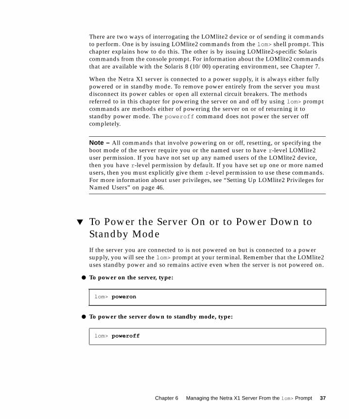
There are two ways of interrogating the LOMlite2 device or of sending it commands
to perform. One is by issuing LOMlite2 commands from the lom> shell prompt. This
chapter explains how to do this. The other is by issuing LOMlite2-specific Solaris
commands from the console prompt. For information about the LOMlite2 commands
that are available with the Solaris 8 (10/00) operating environment, see Chapter 7.
When the Netra X1 server is connected to a power supply, it is always either fully
powered or in standby mode. To remove power entirely from the server you must
disconnect its power cables or open all external circuit breakers. The methods
referred to in this chapter for powering the server on and off by using lom> prompt
commands are methods either of powering the server on or of returning it to
standby power mode. The poweroff command does not power the server off
completely.
Note – All commands that involve powering on or off, resetting, or specifying the
boot mode of the server require you or the named user to have r -level LOMlite2
user permission. If you have not set up any named users of the LOMlite2 device,
then you have r -level permission by default. If you have set up one or more named
users, then you must explicitly give them r -level permission to use these commands.
For more information about user privileges, see “Setting Up LOMlite2 Privileges for
Named Users” on page 46.
▼ To Power the Server On or to Power Down to
Standby Mode
If the server you are connected to is not powered on but is connected to a power
supply, you will see the lom> prompt at your terminal. Remember that the LOMlite2
uses standby power and so remains active even when the server is not powered on.
● To power on the server, type:
● To power the server down to standby mode, type:
lom> poweron
lom> poweroff
Chapter 6 Managing the Netra X1 Server From the lom> Prompt 37

▼ To Display the lom> Prompt
When you connect a terminal to the Serial A/LOM port, you will see the lom>prompt only if the server is powered off. If it is powered on and it has not already
been put into LOM mode, it will display the console prompt.
● To display the lom> prompt, type the following LOMlite2 escape sequence:
When you type the LOMlite2 escape sequence, the LOMlite2 device takes control of
the Serial A/LOM port and the lom> prompt appears on your terminal screen. You
can type the LOMlite2 escape sequence at any time.
Note – If you are at the console and you type the first character of the LOM escape
sequence (by default this is #), there is a delay of one second before the character
appears on the screen. This is because the server waits to see if you type the dot (.)
character next. If you do, the lom> prompt is displayed. If you do not, the #character appears on the screen.
For information about changing the first character of the LOMlite2 escape sequence,
see Chapter 7.
▼ To Exit From the lom> Prompt
● To return to the Solaris console prompt from the lom> prompt, type:
Note – If you have the Serial A/LOM port dedicated to the LOMlite2 device
(instead of shared between the LOMlite2 and the console), this command will have
no effect. For information about dedicating the Serial A/LOM port to the LOMlite2
device, see “Separating LOMlite2 From the Console on the Serial A/LOM Port” on
page 52.
# #.
lom> console
38 Netra X1 Server User’s Guide • December 2000

Note – If you have set up named users of the LOMlite2 device, the users need
c -level permission to use the console command. Without it, the command will not
work. For more information about setting up user permissions, see “Setting Up
LOMlite2 Privileges for Named Users” on page 46.
▼ To Reset the Server
● To reset the server, type:
● To perform a limited reset affecting the processor only, type:
The -x option generates the equivalent of an externally initiated reset (XIR) of the
server. You must have r -level permission to use this command. (For information
about user authorization levels, see “Setting Up LOMlite2 Privileges for Named
Users” on page 46.) The -x option takes the server into OpenBootTM PROM mode
and causes it to display the ok prompt. It is useful for driver or kernel debugging,
because most of the contents of the server’s memory and registers are preserved.
The server does not automatically return to the Solaris environment when you reset
it using the -x option. Instead, you must reboot it from the ok prompt.
▼ To Display the ok or kadb Prompt
To display the ok or kadb prompt, type the following at the lom> prompt:
Note – If the Serial A/LOM port is dedicated to the LOMlite2 device, this command
will have no effect. For information about dedicating the Serial A/LOM port to the
LOMlite2 device, see “Separating LOMlite2 From the Console on the Serial A/LOM
Port” on page 52. To use the break command, you must have c -level LOMlite2 user
privileges. For more information, see “Setting Up LOMlite2 Privileges for Named
Users” on page 46.
lom> reset
lom> reset -x
lom> break
Chapter 6 Managing the Netra X1 Server From the lom> Prompt 39

Controlling the Server’s Booting Behavior
The LOMlite2 shell includes a bootmode command:
bootmode [-u][normal|forth|reset_nvram|diag|skip_diag]
This command enables you to dictate the behavior of the server after a reset. Its
functionality is identical to that available on Sun keyboards with the L1 key
combinations. (However, the bootmode command is provided because the L1 key
combinations are not available for the Netra X1 server: you cannot use them from a
keyboard that is connected to the server with a serial link.)
You must have r -level LOMlite2 permission to use the bootmode command. For
information about user privileges, see “Setting Up LOMlite2 Privileges for Named
Users” on page 46.
Boot Modes Available
If you use the bootmode command without arguments, the LOMlite2 device reports
only the current boot mode. The boot modes available are listed in TABLE 6-1.
TABLE 6-1 Boot Modes
Mode Description
-u This option does not represent a boot mode. However, if you have
previously dedicated the Serial A/LOM port to LOMlite2 and you
now want to share the port between the console and LOMlite2, you
can use the -u option. It is a quick alternative to the procedure
described for sharing the Serial A/LOM port in the section
“Separating LOMlite2 From the Console on the Serial A/LOM Port”
on page 52.
normal In this mode, the server boots using your OpenBoot PROM settings.
To cause this parameter to take effect, you must reset the server
after using the bootmode command at the lom> prompt.
forth In this mode, the server does not boot to the Solaris environment
but stops the boot cycle at the ok prompt. The command is
equivalent to the L1-F key combination for Sun keyboards. To cause
the parameter to take effect, you must use the bootmode forthcommand at the lom> prompt and then reset the server. (It is only
when the server resets that it reads the new forth parameter from
the LOMlite2 device.)
40 Netra X1 Server User’s Guide • December 2000

Monitoring the Server From theLOMlite2 Shell
This section describes the commands that enable you to check the status of the
server and the components monitored by the LOMlite2 device. It also describes how
to view the events stored in the LOMlite2 device’s event log.
▼ To Check How Long the Server Has Been
Running
● To find out how long it is since the last system reset, type:
or:
reset_nvram In this mode, the server returns all NVRAM data to its default
setting. The command is equivalent to the L1-N key combination
for Sun keyboards. To cause the parameter to take effect, you must
reset the server after using the bootmode command at the lom>prompt.
diag In this mode, the server performs full self-diagnostics as part of the
boot process. The command is equivalent to the L1-D key
combination for Sun keyboards. To cause the parameter to take
effect, you must power off and then power on the server within 10
minutes of using the bootmode command at the lom> prompt.
skip_diag In this mode, the server skips the diagnostics part of the boot
process. To cause the parameter to take effect, you must power off
and then power on the server within 10 minutes of using the
bootmode command at the lom> prompt.
lom> date
lom> showdate
TABLE 6-1 Boot Modes
Mode Description
Chapter 6 Managing the Netra X1 Server From the lom> Prompt 41

▼ To Check the Current Status of All Components
● To see the current status of all the components monitored by the LOMlite2 device,type:
CODE EXAMPLE 6-1 shows some sample output from the environment command. In
this example, all the components are running normally and none are faulty.
Note – For the locations of the fans, see “Checking the Fans” on page 56.
CODE EXAMPLE 6-1 Sample Output From the environment Command
lom> environment
lom> environmentFault OFFAlarm 1 OFFAlarm 2 OFFAlarm 3 OFF
Fans:1 OK speed 99%2 OK speed 95%
PSUs:1 OK
Temperature sensors:1 28degC OK
Overheat sensors:1 OK
Circuit breakers:1 OK
Supply rails:1 OK2 OK3 OK4 OK5 OK
lom>
42 Netra X1 Server User’s Guide • December 2000

Viewing the LOMlite2 Event Log
FIGURE 6-1 shows a sample event log display. The eventlog command reports the
last 10 events. The loghistory command can report up to several hundred events.
Note that the first event is the oldest and that each event has a time stamp indicating
the hours and minutes (and, if applicable, days) since the following:
■ The LOMlite2 device was last powered off (that is, since all power to the server,
including standby power, was last removed) or
■ If the server has been booted since all power was last removed, then the time
stamp indicates the number of days, hours, and minutes since the last reboot.
▼ To View the Last 10 Events in the Event Log
● Type:
▼ To View the Entire Event Log
● Type:
where x is the number of lines you want to display before pausing, and y is the
severity level of the events you want to see. By default, the loghistory command
displays all the events in the log and does not pause the display.
If you specify a severity level, you will see reports for the level you specify and
above. For example, if you specify level 2, you will see reports of level 2 and level 1
events. If you specify level 3, you will see reports of level 3, level 2, and level 1
events.
If you do not specify a level, you will see events for all levels.
For more information about severity levels, see “Viewing Event Reports That
LOMlite2 Sends to syslogd” on page 53.
lom> show eventlog
lom> loghistory [pause x] [level y]
Chapter 6 Managing the Netra X1 Server From the lom> Prompt 43

Each entry in the log includes the time of the event, the server’s host name, a unique
identifier for the event, and a user-friendly text message describing the event.
Note – The LOMlite2 device’s Event Log is never cleared, and it can contain several
hundred entries. Events are stored from the very first time the server boots.
Eventually the buffer might become full, but when this happens, the LOMlite2
device will start again at the beginning of the buffer, overwriting the earliest events.
▼ To View All Events From the First to the nth
Event Logged
● Type:
where n is the number of events you want to see that have been logged since the first
event in the current log, x is the number of lines you want to display before pausing,
and y is the severity level of the events you want to see. By default, the loghistorycommand does not pause the display.
▼ To View All Events From the Last One Logged
to the nth Event Before It
● Type:
where n is the number of events you want to see listed that were logged before the
last event in the current log, x is the number of lines you want to display before
pausing, and y is the severity level of the events you want to see. By default, the
loghistory command does not pause the display.
lom> loghistory index + n [pause x] [level y]
lom> loghistory index - n [pause x] [level y]
44 Netra X1 Server User’s Guide • December 2000

● To see the last five events, type:
Verifying That a Component Has Been Fixed
If a monitored component has failed, the LOMlite2 device does not continue to
report the failure. You can, however, check the status of a component, for example,
after attempting to fix it.
▼ To Check the Status of a Component
● Type:
This causes the LOMlite2 device to update the status of all the components it
monitors.
lom> loghistory index -5+0h39m34s Alarm 1 ON+0h39m40s Alarm 3 ON+0h39m54s Alarm 3 OFF+0h40m0s Alarm 1 OFF+0h40m58s Fault LED ON
lom> check
Chapter 6 Managing the Netra X1 Server From the lom> Prompt 45

Setting Up LOMlite2 Privileges forNamed Users
You can specify up to four named users of the LOMlite2 device on a Netra X1 server.
By default, no users are set up, and therefore no user login prompt appears when
you use the LOM escape sequence.
However, if you set up one or more users, every time you use the LOM escape
sequence to display the lom> prompt, you will be prompted for a user name and
password. Therefore, one of the user accounts you set up must be for yourself.
Permissions Available for LOMlite2 Users
Four areas of authorization are available for named users. By default, all four are
open to them. However, if you specify any (using the lom> userperm command),
only the one or ones that you specify will be available.
The four areas of authorization available by default are:
■ Console permission (c -level)This enables the named user to exit from the lom> prompt to the Solaris prompt
(if the Serial A/LOM port is shared between the LOMlite2 and the console).
■ User Administration permission (u-level)This enables the named user to add and delete users and alter their permissions.
■ Administration permission (a-level)This enables the named user to change the LOMlite2 device’s configuration
variables (see “Introduction to Lights-Out Management” on page 36).
■ Reset permission (r -level)This enables the user you have named to reset the server and to power it on and
off using the LOMlite2 device.
For information about how to specify one or more of these areas of authorization for
a named user, see “To Specify Permissions for a Named User” on page 49.
46 Netra X1 Server User’s Guide • December 2000

▼ To Create a LOMlite2 User Account
● Type:
where the username is up to eight characters long, begins with an alphabetic
character, and contains at least one lowercase alphabetic character. You can use any
of the following characters in the user name:
■ Alphanumeric
■ Period (.)
■ Underscore (_)
■ Hyphen (-)
Note – You must have User Administration (u-level) authorization to add a user
(see “Permissions Available for LOMlite2 Users” on page 46). If you have not added
any users, you have a-level and all other levels of authorization by default.
▼ To Specify the Password for a LOMlite2 User
Account
● Type:
where the username is the name of a LOMlite2 user account that already exists.
Note – You must have User Administration (u-level) authorization to set a
password for a user (see “Permissions Available for LOMlite2 Users” on page 46).
lom> useradd username
lom> userpassword username
Chapter 6 Managing the Netra X1 Server From the lom> Prompt 47

▼ To View the Details of a LOMlite2 User Account
● Type:
where the username is the name of an existing LOMlite2 user account.
Note – You must have User Administration (u-level) authorization to view the
details of a LOMlite2 user account (see “Permissions Available for LOMlite2 Users”
on page 46).
▼ To Change Your Own User Password
1. To change the password for the account you are currently logged into, type:
2. When prompted, specify the current password.
3. When prompted, specify the new password you want to use.
4. Specify the new password again to confirm it.
▼ To Delete a LOMlite2 User Account
● Type:
where the username is the name of an existing LOMlite2 user account.
Note – You must have User Administration (a-level) authorization to delete a user
account (see “Permissions Available for LOMlite2 Users” on page 46).
If you delete all the users you have set up, you will no longer see the login prompt
when you go to the lom> prompt.
lom> usershow username
lom> password
lom> userdel username
48 Netra X1 Server User’s Guide • December 2000

By default, all four areas of authorization are available to each named user you set
up. You can limit users to a particular area or areas of authorization by specifying
permissions for a named user.
▼ To Specify Permissions for a Named User
● Type:
You can specify:
■ No parametersThis makes all four areas available to the named user.
■ All four parameters (for example, userperm cuar )
This also makes all four areas available to the named user.
■ One, two, or three parametersThis makes only the parameter or parameters you specify available.
The parameters are:
■ cThis stands for “console permission”. It enables the named user to exit from the
lom> prompt to the Solaris prompt (as long as the Serial A/LOM port is shared
between the LOMlite2 and the console).
■ uThis stands for “user administration permission”. It enables the named user to
add and delete users and alter their areas of authorization by using the userpermcommand.
■ aThis stands for “administration permission”. It enables the named user to change
the LOMlite2 device’s configuration variables (see “Setting the LOMlite2 Device’s
Configurable Variables” on page 50).
■ rThis stands for “reset permission”. It enables the user you have named to reset
the server and to power it on and off using the LOMlite2 device.
lom> userperm username [c][u][a][r]
Chapter 6 Managing the Netra X1 Server From the lom> Prompt 49

▼ To Quit a LOMlite2 Named User Session
● Type:
This returns you to the LOMlite2 login prompt.
Setting the LOMlite2 Device’sConfigurable Variables
There are some variables that you can use as arguments to the set command in the
LOMlite2 shell. The set command duplicates the faulton , faultoff , alarmon,and alarmoff commands by taking them as arguments. It also takes the argument
event_reporting , which enables you to stop the LOMlite2 device from sending
event reports to the Serial A/LOM port.
Note – To be able to run the commands described in this section, a named user must
have a-level permission. For more information, see “Setting Up LOMlite2 Privileges
for Named Users” on page 46.
▼ To Turn the Fault LED On and Off
● To turn the Fault LED on by setting the faulton variable, type:
● To turn the Fault LED off by setting the faultoff variable, type:
lom> logout
lom> set faulton
lom> set faultoff
50 Netra X1 Server User’s Guide • December 2000

▼ To Set the Alarm
● Turn the alarm on by typing:
where n is the number of the alarm you want to turn on: 1, 2, or 3.
● Turn the alarm off by typing:
where n is the number of the alarm you want to turn off: 1, 2, or 3.
▼ To Stop LOMlite2 Sending Event Reports to the
Serial A/LOM Port
● Enable event reporting by typing:
Note – This is the equivalent of using the lom -E on command from the Solaris
shell. For more information, see “To View the Event Log (lom -e)” on page 63.
● Disable event reporting by typing:
Note – This is the equivalent of using the lom -E off command from the Solaris
shell. For more details, see “To Stop LOMlite2 From Sending Reports to the Serial A/
LOM Port (lom -E off)” on page 68.
lom> set alarmon n
lom> set alarmoff n
lom> set eventreporting on
lom> set eventreporting off
Chapter 6 Managing the Netra X1 Server From the lom> Prompt 51

Separating LOMlite2 From the Consoleon the Serial A/LOM Port
By default, the LOMlite2 device shares the Serial A/LOM port with the console, and
when it has an event report to send, it takes control of the Serial A/LOM port itself,
interrupting any console activity you are performing. To prevent the LOMlite2
device from interrupting the console, either turn serial event reporting off (see
Chapter 7), or dedicate the Serial A/LOM port to the LOMlite2 device and use the
Serial B port for console activity. The next section, “To Dedicate Serial A/LOM to
LOMlite2” on page 52, gives more detail.
The advantages of dedicating the Serial A/LOM port to the LOMlite2 device and
using Serial B as your console port include:
■ Preserving the ability to power on or reset the server (from the lom> prompt on
Serial A/LOM) even if for any reason you lose access to Solaris on your console
port (Serial B).
■ Capturing all LOMlite2 events passively on a terminal connected to the dedicated
LOM port (Serial A/LOM). Note, however, that if you dedicate the Serial A/LOM
port to the LOMlite2 device, you cannot use the console command to quit the
LOMlite2 shell. Instead, for access to the Solaris environment, you must connect
to the server using the Serial B port.
■ Preventing a user with console access from using the LOMlite2 escape sequence
to exit the Solaris environment and access the LOMlite2 shell. If you dedicate the
Serial B port to the console, users cannot bring up the LOMlite2 shell, which
means that they cannot interrogate or reconfigure the LOMlite2 device.
■ Performing binary data transfers. To perform any task other than an ASCII
transfer, you must use the Serial B port.
▼ To Dedicate Serial A/LOM to LOMlite2
1. Set up console connections to both the Serial A/LOM port and the Serial B port.
2. At the Solaris prompt, type:
# eeprom input-device=ttyb# eeprom output-device=ttyb# reboot
52 Netra X1 Server User’s Guide • December 2000

The Serial B port (ttyb) is now your console port. The Serial A/LOM port remains in
the control of the LOMlite2 device.
▼ Sharing Serial A/LOM Between LOMlite2 and
the Console
Note – By default, the Serial A/LOM port is shared by the LOMlite2 device and the
console. Therefore, you should follow the instructions in this section only if you
have configured the server by using the instructions in the previous section (“To
Dedicate Serial A/LOM to LOMlite2” on page 52) and you now want to share the
Serial A/LOM port between LOMlite2 and the console.
1. Set up console connections to both the Serial A/LOM port and the Serial B port.
2. At the Solaris prompt, type:
The Serial A/LOM port (ttya) is now shared between the LOMlite2 device and the
console.
Viewing Event Reports That LOMlite2Sends to syslogdThe LOMlite2 device monitors the status of the fans, supply rails, temperature, and
power supply even when the server is powered off (the LOMlite2 device operates on
standby power). If it detects a fault, it turns on the Fault LED on the server’s front
and back panels and stores a report in an event log, which resides in memory on the
LOMlite2 device. When the Solaris environment is running, the LOMlite2 device
also sends event reports to syslogd . The syslogd handles these in the way it has
been configured to handle event reports. This means that by default it sends them to
the console and stores them in:
/var/adm/messages
# eeprom input-device=ttya# eeprom output-device=ttya# reboot
Chapter 6 Managing the Netra X1 Server From the lom> Prompt 53

In this file, the reports are displayed with a label identifying them as lom reports
and indicating their severity. In descending order, the levels of severity are:
1. Fatal
These events might indicate, for example, exceeded temperature thresholds or
supply rail failures. Fatal events can cause the server to shut itself down.
2. Warning
These events might indicate fans turning too slowly, the Fault LED having been
turned on, or the System Configuration Card having been removed. They are not
events that cause the server to shut down, but they do require immediate attention.
3. Info
These events are most likely to inform you that some problem is now OK. For
example, if you reinsert the System Configuration Card, the LOMlite2 device will
generate an event to say that the System Configuration Card has been restored.
4. User
User level events indicate the activity of named users whom you have authorized to
access the LOMlite2 device. For example, an event is generated when a user logs in
or out.
LOMlite2 Shell Command List
The commands you can use from the lom> prompt are listed in TABLE 6-2.
TABLE 6-2 LOM Commands
Command Description
alarmoff n Sets alarm n off, where n is 1, 2, or 3. These three alarms are software
flags. They are associated with no specific conditions but are available
to be set by your own processes.
alarmon n Sets alarm n on. See the description for the alarmoff command.
break Takes the server down to the ok prompt.
bootmode Determines the behavior of the server during the boot process.
check Resets monitoring to report all failures. If a monitored component has
failed, the LOMlite2 device will not continue to report the same
failure. To check the status of the component, for example, after
attempting to fix it, use the check command. This updates the status
of all monitored components.
54 Netra X1 Server User’s Guide • December 2000

console Takes you out of the LOMlite2 shell and back to the Solaris prompt. It
returns control of the serial connection to the console.
environment Displays the temperature of the server and the status of the fans, the
power supply, the overtemperature monitors, the supply rails and
circuit breakers, the alarms, and the fault LED.
faulton Sets the Fault LED to On.
faultoff Sets the Fault LED to Off.
help Displays the list of LOM commands.
loghistory Displays all the events in the LOMlite2 device’s Event Log.
logout Returns named users you have set up with password access to the
LOM user login prompt.
poweron Powers the server on.
poweroff Powers the server down to standby power mode.
reset Resets the server.
show model Displays the server model.
show hostname Displays the server name (this command is equivalent to the Solaris
uname -n command).
show eventlog Displays the LOMlite2 device’s event log. The event log is the list of
the last 10 events stored in the LOMlite2 device. The most recent
event is the one at the bottom of the list.
show escape Displays the current LOMlite2 escape sequence.
show Displays all the information available with the show command.
useradd Adds a user to the LOMlite2 device’s list of permitted users.
userdel Deletes a user from the LOMlite2 device’s list of permitted users.
usershow Displays the details of a named user’s LOMlite2 account.
userpassword Sets or changes a user’s password.
userperm Sets the permission levels for a named user.
version Displays the version number of the LOMlite2 device.
TABLE 6-2 LOM Commands (Continued)
Command Description
Chapter 6 Managing the Netra X1 Server From the lom> Prompt 55

Checking the Fans
Event reports about the fans inside the server include the number of the fan to
which they relate. The fans monitored are fans 1 and 2, which expel hot air from the
server. For the location of the fans, see “Identifying Components” on page 87.
▼ To Check the Status of the Fans
● Type:
lom> environment
56 Netra X1 Server User’s Guide • December 2000

CHAPTER 7
Managing the Netra X1 Server Fromthe Solaris Prompt
This chapter describes how to monitor and manage the Netra X1 server with
LOMlite2-specific commands in the Solaris 8 (10/00) environment. It contains the
following sections:
■ “Monitoring the System From the Solaris Prompt” on page 58
■ “Configuring LOMlite2 to Restart the Server Automatically After a Lockup” on
page 64
■ “Other LOM Tasks You Can Perform From the Solaris Prompt” on page 67
Note – For information about how to configure the LOMlite2 device driver, see
Appendix A.
Note – The Netra X1 server is supplied with the Solaris 8 (10/00) operating
environment installed and with the supplementary LOM software (described in this
chapter and in Chapter 6) also installed. This software enables you to manage the
Netra X1 server locally or remotely. If you ever need to reinstall the Solaris 8
environment and you want to use the LOM facilities, you must also reinstall the
Netra X1 LOM software from the CD named Software Supplement for the Solaris 8Operating Environment. This CD is included with the Solaris 8 software CDs. The
LOM software is in the following directory: /Netra_t_Lights_Out_Management_2.0 . The three packages you need are:
SUNWlomm, SUNWlomr, and SUNWlomu.
57

Monitoring the System From the SolarisPrompt
To use the Lights-Out Management (LOM) facilities either remotely or locally, you
need a terminal connection to the Serial A/LOM port on the server (see Chapter 6).
There are two ways to interrogate LOMlite2 or to send it commands to perform:
■ Use LOMlite2 commands from the lom> shell prompt. For information about how
to do this, see Chapter 6.
■ Use LOMlite2-specific Solaris commands from the Solaris prompt. These
commands are described in this chapter.
All Solaris commands described in this section are available from the main Solaris #prompt. They run a utility called /usr/sbin/lom .
Where appropriate, the command lines given in this section are accompanied by
typical output from the commands.
There are also manual pages for the LOMlite2 utility.
▼ To View the LOMlite2 Online Documentation
● To view the manual pages for the LOMlite2 utility, type:
▼ To Check the Power Supply Unit (lom -p )
● To check whether the input lines and the output line for the power supply unitare working normally, type:
# man lom
# lom -pPSU:1 OK
#
58 Netra X1 Server User’s Guide • December 2000

▼ To Check the Fan Status (lom -f )
● Type:
Checking the Supply Rail Voltages and Internal
Circuit Breakers (lom -v )
The supply rails are the Netra X1 server’s internal power lines. If the status of any of
these is faulty , contact your local Sun sales representative. It means that you have
either a faulty system board or a faulty PSU.
The -v option also displays the status of the server’s internal circuit breakers. For
any that have been tripped, the status will read faulty . The system contains three
circuit breakers: one for each of the USB ports and one for the system configuration
card reader.
If there is a problem with the circuit breakers or the USB port circuit breakers,
remove the device connected to the relevant port and the circuit breakers will
automatically recover.
If there is a problem with the circuit breaker for the system configuration card, it
means either that the system configuration card is inserted incorrectly, or is broken.
Insert a valid one to check.
# lom -fFans:1 OK speed 99%
#
Chapter 7 Managing the Netra X1 Server From the Solaris Prompt 59

▼ To Check the Status of the Supply Rails and
Internal Circuit Breakers
● Type:
▼ To Check the Internal Temperature
● Type:
This checks the server’s internal temperature, and the warning and shutdown
threshold temperatures.
# lom -vSupply voltages: 1 5V status=ok 2 3V3 status=ok 3 +12V status=ok 4 -12V status=ok 5 VDD-CORE status=ok
System status flags (circuit breakers):1 USB0 status=ok2 USB1 status=ok
# lom -tSystem Temperature Sensors:1 enclosure 25 degC : warning 67 degC : shutdown 72 degC
System Over-temperature Sensors:1 cpu status=ok#
60 Netra X1 Server User’s Guide • December 2000

▼ To Check Whether the Fault LED and Alarms
Are On or Off
● Type:
Alarms 1, 2, and 3 are software flags. They are not associated with any specific
conditions, but are available to be set by your own processes or from the command
line. For more information, see “To Turn the Alarms On and Off (lom -A)” on
page 67.
▼ To Change the LOMlite2 Watchdog
Configuration (lom -w )
For full information about enabling and using the LOMlite2’s watchdog process, see
“To Configure the LOMlite2 Watchdog to Restart the System After a Lockup” on
page 64.
● To find out how the LOMlite2 watchdog is currently configured, type:
The LOMlite2 watchdog is enabled by default when the Solaris environment boots.
This means that, by default, if the watchdog does not receive a “pat” for 40,000
milliseconds, it will turn on the Fault LED on the front and back panels of the
system, generate a LOM event report, and, if configured to do so, perform an
automatic server restart. However, although the watchdog is enabled by default
when Solaris boots, the Hardware reset option is not. This means that the
LOMlite2 device does not, by default, automatically restart the server after a lockup.
# lom -lLOMlite alarm states:Alarm1=offAlarm2=offAlarm3=offFault LED=on#
# lom -wLOMlite watchdog (ASR) settings:Watchdog=onHardware reset=offTimeout=40 s#
Chapter 7 Managing the Netra X1 Server From the Solaris Prompt 61

● To configure the LOMlite2 device to perform an automatic server restart (ASR)after a lockup, you must enable the Hardware reset option as well as theWatchdog option.
For more information, see “Configuring LOMlite2 to Restart the Server
Automatically After a Lockup” on page 64.
▼ To View the Configuration of LOMlite2
● To view the settings of all the configurable variables for the LOMlite2 device,type:
▼ To View All the Status Data Stored by LOMlite2,
Plus Details of the Device’s Own Configuration
● Type:
# lom -cLOMlite configuration settings:serial escape character=#serial event reporting=defaultEvent reporting level=fatal, warning & informationSerial security=enabledDisable watchdog on break=disabledAutomatic return to console=disabledalarm3 mode=watchdogfirmware version=3.0firmware checksum=2983product revision=0.0product ID=Netra X1 200#
# lom -a
62 Netra X1 Server User’s Guide • December 2000

▼ To View the Event Log (lom -e )
● To see the event log, type:
where n is the number of reports (up to 128) that you want to see and x specifies the
level of reporting you require. There are four levels of event reporting:
1. Fatal events
2. Warning events
3. Information events
4. User events
If you specify a level, you will see reports for that level and above. For example, if
you specify level 2, you will see reports of level 2 and level 1 events. If you specify
level 3, you will see reports of level 3, level 2, and level 1 events.
If you do not specify a level, you will see reports of level 3, level 2, and level 1
events.
FIGURE 7-1 shows a sample event log display. Note that the first event is the oldest
and that each event has a date stamp indicating the days, hours and minutes since
the system was last booted.
FIGURE 7-1 Sample LOMlite2 Device Event Log (Oldest Event Reported First)
# lom -e n, [ x]
# lom -e 10LOMlite Event Log:+0h0m21s host reset9/15/2000 17:35:28 GMT LOM time reference+0h3m20s fault led state - ON+0h3m24s fault led state - OFF+0h39m34s Alarm 1 ON+0h39m40s Alarm 3 ON+0h39m54s Alarm 3 OFF+0h40m0s Alarm 1 OFF+0h48m52s fault led state - OFF+0h49m39s Fan 1 FATAL FAULT: failed+0h50m58s fault led state - ON
# lom -e 10
Chapter 7 Managing the Netra X1 Server From the Solaris Prompt 63

Configuring LOMlite2 to Restart theServer Automatically After a Lockup
You can configure LOMlite2 to restart the server automatically after a lockup.
LOMlite2 has a watchdog process that, by default, expects to be patted every 10,000
milliseconds. If it does not receive a pat after 40,000 milliseconds (default), then
LOMlite2 turns the front and back fault LEDs on and generates a LOM event report.
However, it does not automatically restart the system unless you have configured it
to do so.
▼ To Configure the LOMlite2 Watchdog to Restart
the System After a Lockup
● Add the -R option to the piocntl command in the script file called /etc/rc2.d/S25lom .
This is the script that runs the LOMlite2 watchdog process:
When you have done this, LOMlite2 will restart the server whenever the watchdog
times out.
You can turn the option on and off from the Solaris command prompt. For more
information, see “To set the Hardware Reset Option From a Script or Command (lom
-R on)” on page 66.
However, as long as you have the -R on option set in /etc/rc2.d/S25lom , the
Hardware Reset option will always be enabled when you start the system.
# piocntl -e -c RT lom -W on,40000,10000 -R on
64 Netra X1 Server User’s Guide • December 2000

Enabling the LOMlite2 Watchdog Process From
Your Own Script or Command (lom -W on )
Note – You do not normally need to do this. If you want to configure LOMlite2 to
perform an automatic server restart after a lockup, see “To Configure the LOMlite2
Watchdog to Restart the System After a Lockup” on page 64. Use the lom -W onoption on the command line or in another script file only if you have removed the
/etc/rc2.d/S25lom script.
By default, the LOMlite2 watchdog process is enabled, and if you type
lom -W on while the watchdog process is already running, the command will have
no effect. You can run this command only if you have removed the
/etc/rc2.d/S25lom script file, or if you have turned the watchdog off manually
by using the lom -W off command.
The default piocntl command is:
piocntl -e -c RT lom -W on,40000,10000
The number 40,000 on this command line indicates the watchdog’s timeout period in
milliseconds; you can specify a different number. The number 10,000 indicates its pat
interval in milliseconds; again, you can specify a different number.
Note – Do not specify a watchdog timeout period of less than 5000 milliseconds. If
you do, the watchdog times out frequently even though the server has not locked
up.
If the watchdog process times out (in other words, if it does not receive its expected
pat), the LOMlite2 device will turn on the server’s front and back Fault LEDs and
generate a LOM event report. However, it will not automatically reset the system. To
make it reset the system, you must use the -R option. For more information, see “To
set the Hardware Reset Option From a Script or Command (lom -R on)” on page 66.
● If you have no LOMlite2 watchdog process running already and you want theprocess to run, type the following, or add it to another script file:
● If you want the LOMlite2 device to perform an automatic server restart after alockup, you must include the -R on option in the command, as follows:
# lom -W on,40000,10000
# lom -W on,40000,10000 -R on
Chapter 7 Managing the Netra X1 Server From the Solaris Prompt 65

Note – Unless you include the lom -W on and -R on options in a script file, you
must run the lom command every time you reboot the system if you want to use the
automatic server restart facility. Otherwise the watchdog will not run, and the server
will not reset after a lockup.
▼ To set the Hardware Reset Option From a
Script or Command (lom -R on )
To make the LOMlite2 device’s watchdog process trigger an automatic server restart
(ASR) after a lockup, add the -R on option to the command in your
/etc/rc2.d/S25lom script file. This is the script that runs the watchdog. For
instructions about how to do this, see “To Configure the LOMlite2 Watchdog to
Restart the System After a Lockup” on page 64.
However, if for any reason you are not using the script file provided with your
system (/etc/rc2.d/S25lom ) but have instead enabled the watchdog from the
command line or from another script file, you can turn the Hardware reset option
on.
● To turn the Hardware reset option on, type the following at the command line:
● To turn the Hardware reset option off from the command line, type:
# lom -R on
# lom -R off
66 Netra X1 Server User’s Guide • December 2000

Other LOM Tasks You Can PerformFrom the Solaris Prompt
This section describes how to:
■ turn the alarms and Fault LEDs on and off with the lom command
■ change the first character of the lom escape sequence
■ stop LOMlite2 sending reports to the Serial A/LOM port
■ remove driver protection from the device driver
■ make the LOMlite2 interface backward compatible
■ upgrade LOMlite2 firmware
▼ To Turn the Alarms On and Off (lom -A )
There are three alarms associated with LOMlite2. They are not associated with
specific conditions but are software flags that can be set either by your own
processes or from the command line.
● To turn an alarm on from the command line, type:
where n is the number of the alarm you want to set: 1, 2, or 3.
● To turn the alarm off from the command line, type:
where n is the number of the alarm you want to turn off: 1, 2, or 3.
▼ To Turn the Fault LED On and Off (lom -F )
● To turn the Fault LED on, type:
# lom -A on, n
# lom -A off, n
# lom -F on
Chapter 7 Managing the Netra X1 Server From the Solaris Prompt 67

● To turn the Fault LED off, type:
▼ To Change the First Character of the Sequence
for Escaping to the lom> Prompt (lom -X )
The character sequence #. (hash, dot) enables you to exit the Solaris prompt to the
lom> prompt.
● To change the first character of this default lom escape sequence, type:
where x is the alphanumeric character you want to use instead of #.
Note – If you are at the console and you type the first character of the LOM escape
sequence (by default this is #), there is a delay of one second before the character
appears on the screen. This is because the system waits to see if you type the dot (.)
character next. If you do, the lom> prompt appears. If you do not, the # character
appears. If you want to change the LOM escape character, use a character that is not
included in any console commands; otherwise the delay between your striking the
key and the character appearing on the screen may affect your typing at the console.
▼ To Stop LOMlite2 From Sending Reports to the
Serial A/LOM Port (lom -E off )
LOMlite2 event reports can interfere with information you are attempting to send or
receive on the Serial A/LOM port. By default, the Serial A/LOM port is shared by
the console and LOMlite2. LOMlite2 interrupts the console whenever it needs to
send an event report. To prevent LOMlite2 from interrupting the console on Serial
A/LOM, turn serial event reporting off.
● To stop LOMlite2 from sending reports to the Serial A/LOM port, type:
# lom -F off
# lom -X x
# lom -E off
68 Netra X1 Server User’s Guide • December 2000

● To turn serial event reporting on again, type:
If you want to dedicate the Serial A/LOM port to the LOMlite2 device and you want
to use the Serial B port as your console port, see Chapter 6.
▼ To Remove Driver Protection From the LOMlite2
Driver (lom -U )
By default, the LOMlite2 driver cannot be unloaded. This is because the driver is
required by the watchdog process. If you unload the driver and you have configured
the system to restart when the watchdog times out, the watchdog will time out,
causing a system reset. For information about configuring the system to restart
automatically after a lockup, see “Configuring LOMlite2 to Restart the Server
Automatically After a Lockup” on page 64.
To remove driver protection from the LOMlite2 driver so that you can unload the
driver:
1. Turn the watchdog process off by typing:
2. Unload the driver by typing:
# lom -E on
# lom -W off
# lom -U
Chapter 7 Managing the Netra X1 Server From the Solaris Prompt 69

▼ To Make the LOMlite2 Interface Backward
Compatible (lom -B )
If you have scripts written to the LOMlite interface on the Netra T1 Model 100/105
server or the Netra t 1400/1405 server and you want to use these scripts on the
Netra X1 server, you can add file system links that make this possible. To do so,
type:
When you have done this, you will be able to use the old scripts on the new system.
▼ To Upgrade LOMlite2 Firmware
(lom -G filename)
To upgrade the firmware for LOMlite2, obtain the new firmware package from the
SunSolveSM website (http://sunsolve.sun.com). or from your local Sun sales
representative, and type the following:
where filename is the name of the file containing the new firmware.
Note – LOMlite2 firmware upgrades will be released as patches and will include
detailed installation instructions.
# lom -B
# lom -G filename
70 Netra X1 Server User’s Guide • December 2000

PART III Troubleshooting and Maintenance


CHAPTER 8
Troubleshooting
This chapter lists some of the problems you might encounter when setting up or
using a Netra X1 server, and offers some suggestions on how to fix them. The
information is contained in the section:
■ “Solutions to Problems You Might Encounter” on page 74
73

Solutions to Problems You MightEncounter
Cannot Set Up a Console Connection to the Server
The Netra X1 server’s serial port pinouts are listed in Chapter 4. Verify that they are
correct for the device (that is, the terminal or terminal server) that you are
connecting to the Netra X1 server.
Cannot Display the lom> Prompt Using the #. Escape Sequence
Check whether the first character of the #. escape sequence has been changed (this
is a user-configurable value). To check the current value, type the following from the
Solaris prompt:
The information that this command displays includes the serial escape character. If
this is not “#”, then type the character that is currently specified and follow it
immediately with a dot.
Cannot Turn Serial Event Reporting On and OffCannot Receive Clearly Formatted LOMlite2 OutputCannot Reprogram the LOMlite2 Device
If you have reinstalled the Solaris 8 (10/00) operating environment on your server
and have also reinstalled the LOMlite2 software from the support CD (titled SoftwareSupplement for the Solaris 8 Operating Environment), you need to apply the latest
version of patch 110208-xx. This patch is available on the SunSolveSM website
(http://sunsolve.sun.com).
# lom -c
74 Netra X1 Server User’s Guide • December 2000

Cannot Display the lom> Prompt or the Solaris PromptReceiving Corrupted Text at the Console on Serial A/LOMCannot Access the Server From the Console
First, try resetting the LOMlite2 device. To do this, connect remotely (using the
rlogin hostname or telnet hostname command), and type:
If resetting the LOMlite2 device does not fix the problem, reprogram the LOMlite2
device by using the firmware supplied in patch 110208-xx. First apply the patch, and
then download the new firmware by typing:
where filename is the name of the file containing the new firmware.
OpenBoot PROM Initialization Aborts and the Server Will Not Boot
If the OpenBoot PROM initialization sequence aborts and the message “NO
IDPROM” is displayed when the operating system is attempting to read the serial
number and MAC address, then you are attempting to boot without a valid system
configuration card (SCC) inserted. The SCC contains the serial number, MAC
address, and NVRAM settings for the Netra X1 server. For more information about
the SCC, see “Replacing an Entire Netra X1 Server” on page 82.
# lom -G resetlom
# lom -G filename
Chapter 8 Troubleshooting 75

76 Netra X1 Server User’s Guide • December 2000

CHAPTER 9
Interpreting the LEDs
This chapter describes the location, function, and meaning of the Netra X1 server’s
warning LEDs, and contains the following sections:
■ “Interpreting the Front- and Back-Panel LEDs” on page 78
77

Interpreting the Front- and Back-PanelLEDs
The Netra X1 server contains two front panel LEDs (see FIGURE 9-1) and four rear
panel LEDs (see FIGURE 9-2). Those on the front panel indicate power and faults only.
Those on the back panel indicate the presence of up to two ethernet connections, and
replicate the power and fault information of the front LEDs.
Front-Panel LEDs
The front panel LEDs are located at the top left of the server’s front bezel.
FIGURE 9-1 Front-Panel Power and Fault LEDs
■ Power LEDThis LED is lit when the server is powered on. It is unlit when the server is in
standby mode.
■ Fault LEDThe Fault LED is constantly on when a problem has occurred that is not fatal to the
server but that you should attend to as soon as possible. Circumstances that cause
this include the following:
Power LED
Fault LED
78 Netra X1 Server User’s Guide • December 2000

■ The temperature inside the server’s enclosure is unusually high.
■ The voltage on one of the server’s output supply rails is unusually high.
■ One of the server’s internal circuit breakers has tripped.
■ The system configuration card, containing the server’s serial number, MAC
address, and NVRAM settings, has been removed.
■ The LOMlite2 watchdog has timed out, indicating that the server has locked
up. You can configure the server to restart automatically after a lockup (see
Chapter 7).
The Fault LED flashes when a problem has occurred that is fatal to the server.
Circumstances that cause the Fault LED to flash include the following:
■ The speed of the fan inside the server is too low.
■ The temperature inside the server’s enclosure is too high. By default, this
causes the server to shut down. For information about configuring the server
not to shut down in this condition, see Appendix A.
■ The voltage on one of the server’s output supply rails is too high. By default,
this causes the server to shut down. For information about configuring the
server not to shut down in this condition, see Appendix A.
■ The temperature inside the CPU is too high. This causes the server to shut
down.
Back-Panel LEDs
The Netra X1 server contains four back panel LEDs (see FIGURE 9-2):
■ Ethernet port 0
■ Ethernet port 1
The light corresponding to each Ethernet port (see FIGURE 9-2) comes on to indicate
that a connection has been established to the hub.
■ Fault LEDThis mirrors the Fault LED on the front panel.
■ Power LEDThis mirrors the Power LED on the front panel.
Chapter 9 Interpreting the LEDs 79

FIGURE 9-2 Back-Panel Power and Fault LEDs
▼ To Turn the Fault LED On or Off
● To turn the Fault LED on, type:
● To turn the Fault LED off, type:
For more information about the lom commands included in the Solaris 8 (10/00)
environment, see Chapter 7.
For information about turning the Fault LEDs on and off from the LOMlite2 shell,
see Chapter 6.
# lom -F on
# lom -F off
Power LED
Fault
Ethernet 1
Ethernet 0
80 Netra X1 Server User’s Guide • December 2000

CHAPTER 10
Removing and ReplacingComponents
This chapter details the procedures for moving the system configuration card from
one server to another, and for changing replaceable components. It contains the
following sections:
■ “Replacing an Entire Netra X1 Server” on page 82
■ “Altering a Netra X1 Server” on page 83
81

Replacing an Entire Netra X1 Server
The Netra X1 server contains a memory card called the system configuration card.
This card contains the system’s MAC address, serial number, and other
configuration settings. It is designed to be removable so that, if you ever need to
replace an entire server, you can transfer the host ID and configuration data onto the
new server. This makes the replacement of the server transparent to your network.
▼ To Swap the System Configuration Card (SCC)
Between Servers
1. Make sure that both Netra X1 servers are powered down.
2. Remove the zip ties securing the system configuration cards in both servers, andremove the cards.
3. Insert the system configuration card from the old server into the new one.
4. Replace the zip tie on the new system.
5. Power on the new system (see Chapter 5).
Caution – Never remove the system configuration card when the server is booting
or running Solaris. Power the server off or down to standby mode before removing
or inserting the system configuration card.
Caution – Do not handle the system configuration card unless you need to transfer
it to another system. If you need to handle it for this reason, avoid contact with the
gold terminals on the underside of the card.
82 Netra X1 Server User’s Guide • December 2000

FIGURE 10-1 The System Configuration Card Reader
Altering a Netra X1 Server
The procedures in this section are for the attention of qualified service engineers
only. If you must replace or add a component, contact your local Sun sales
representative, who will put you in touch with the Sun Enterprise Service branch for
your area. You can then arrange to return the system to Sun for repair under the
terms of your warranty or you can order the components and have them installed by
your own qualified service engineers.
Caution – The system contains electronic parts that are extremely sensitive to static
electricity. Do not touch any metal parts. Place the system on top of an electrostatic
discharge (ESD) pad (see FIGURE 10-2). Use the disposable antistatic wrist strap
supplied with the system, and attach it to the metal base of the system before
touching any of the internal components.
Caution – Before attempting to remove the cover, make sure that the server is
powered off and that the power cord, and all other cables, have been disconnected
from it.
Chapter 10 Removing and Replacing Components 83

FIGURE 10-2 Using the Disposable Antistatic Wrist Strap Supplied With the System
▼ To Change Components In a Netra X1 Server
That Is in UseIf the system is currently in use and you need to open it to install a component:
1. Shut down the Solaris environment from the console.
2. Hold the On/Standby switch in the Standby position for more than four secondsto put the server in standby mode.
3. Disconnect the power cord.
4. Disconnect all other cables.
5. If the system is installed in a rack or cabinet, remove it.
84 Netra X1 Server User’s Guide • December 2000

▼ To Remove the Top Cover■ If the Netra X1 server is not in use, go straight to step 1.
■ If the server is already in use, see “Changing a Netra X1 Server that is In Use” on
page 58.
FIGURE 10-3 Removing the Top Cover
1. Place the unit on an ESD surface and attach an antistatic wrist strap (seeFIGURE 10-2).
2. Unscrew the captive screw from the back of the unit (see FIGURE 10-3).
3. Slide the top cover back until the arrow on the cover lines up with the arrow onthe server body.
4. Lift the cover up and off.
Chapter 10 Removing and Replacing Components 85

▼ To Replace the Top Cover
1. Align the arrow on the cover with the arrow on the server body.
2. Press the cover down so that it clips into the server body.
FIGURE 10-4 Replacing the Top Cover
3. Slide the cover forwards so that its leading edge is flush with the back of theserver’s front bezel.
Note – When the cover is in position, the arrows do not line up; the arrow on the
cover is further towards the bezel than the arrow on the server body.
4. Tighten the captive screw on the back of the unit.
86 Netra X1 Server User’s Guide • December 2000

Identifying Components
Viewed from the back with the cover removed, the internal components of the Netra
X1 server are laid out as in FIGURE 10-5. This image, and a summary of the
instructions given in this section, are repeated on the underside of the server’s top
cover.
FIGURE 10-5 Layout of Components
The components shown are
1. Power Supply Unit
2. Fan
3. System Board
4. Hard Disk Drive (HDD) 0 and 1
5. Memory
CPU
System Board
PSU1
Reader
Fan 1
Mem
ory
HDD1
HDD0
4
43
5
2
Chapter 10 Removing and Replacing Components 87

Memory Installation and Removal
There are four industry standard PC133 memory module sockets on the Netra X1
server’s system board. You can install standard 128- or 256-Mbyte dual inline
memory modules (DIMMs) into each socket. For the maximum 1 Gbyte of memory,
install four 256-Mbyte DIMMs.
To see the position of the memory modules inside the server, see FIGURE 10-5 or the
underside of the server’s top cover.
▼ To Install and Remove Memory■ If the server is not in use, go straight to Step 1.
■ If the server is already in use, see “To Change Components In a Netra X1 Server
That Is in Use” on page 84.
1. Place the unit on an ESD surface and attach an antistatic wrist strap (seeFIGURE 10-2)
2. Remove the server’s top cover (see “Removing the Top Cover” on page 58).
3. Insert the memory module in the next vacant DIMM socket.
The memory slots are numbered 3, 2, 1, 0. Add DIMMS in that order.
FIGURE 10-6 DIMM Insertion Order
4. Press the memory module until the latches at the sides of the socket click intoplace.
3 2
10
3210
88 Netra X1 Server User’s Guide • December 2000

FIGURE 10-7 Installing Memory Into a Socket on the System Board
5. If you are removing memory, open the latches and remove the module(s) in theorder 0, 1, 2, 3.
6. Replace the system cover and tighten the captive screw (see FIGURE 10-4).
Hard Disk Drive (HDD) Installation and Removal
The server can accept two HDDs, which are numbered 0 and 1. To see the position of
each HDD, see FIGURE 10-5 or the underside of the server’s top cover.
▼ To Install a Hard Disk Drive■ If the Netra X1 server is not in use, go straight to Step 1.
■ If the server is already in use, see “To Change Components In a Netra X1 Server
That Is in Use” on page 84.
Chapter 10 Removing and Replacing Components 89

1. Place the unit on an ESD surface and attach an antistatic wrist strap (seeFIGURE 10-2).
2. Remove the server’s top cover (see “To Remove the Top Cover” on page 85).
3. Remove the metal placeholder if your server has one (if it was configured with asingle hard disk drive, the second hard disk drive slot will have the placeholderinstalled).
FIGURE 10-8 Removing the HDD Placeholder
4. Insert and align the new hard disk drive (see FIGURE 10-9).
a. Position HDD and slide onto the clips on the base of the server.
b. Press the handle into the two clips on the base of the server.
90 Netra X1 Server User’s Guide • December 2000

FIGURE 10-9 Installing a Hard Disk Drive
5. Attach the power and data cables.
FIGURE 10-10 Attaching the Power and Data Cables
6. Replace the system cover and tighten the captive screw (see FIGURE 10-4).
Step 4a
Step 4b
Chapter 10 Removing and Replacing Components 91

▼ To Remove a Hard Disk Drive■ If the Netra X1 server is not in use, go straight to Step 1.
■ If the server is already in use, see “Changing a Netra X1 Server that is In Use” on
page 58.
1. Place the unit on an ESD surface and attach an antistatic wrist strap (seeFIGURE 10-2).
2. Remove the server’s top cover (see “To Remove the Top Cover” on page 85).
3. Disconnect the data and power cables.
4. Unfasten the hard disk drive’s handle from the two clips securing it.
5. Slide the hard disk drive towards the centre of the server until it is free from theclips on the base of the server.
6. Lift the hard disk drive up and out of the server.
92 Netra X1 Server User’s Guide • December 2000

PART IV Appendix


APPENDIX A
Configuring the Driver forLOMlite2
This appendix describes the parameters that you can use to configure the LOMlite2
driver, and contains the following sections:
■ “The LOMlite2 Device Driver and Script Files” on page 96
■ “Configuring the LOMlite2 Device Driver” on page 97
95

The LOMlite2 Device Driver and ScriptFiles
The LOMlite2 driver software included in the Solaris 8 (10/00) operating
environment is as follows:
■ /platform/sun4u/kernel/drv/lom (the lom driver [32-bit])
■ /platform/sun4u/kernel/drv/sparcv9/lom (the lom driver [64-bit])
■ /platform/sun4u/kernel/drv/lom.conf (the driver configuration file)
The driver is started by the following three scripts in the Solaris 8 (10/00)
environment:
■ /etc/init.d/lom
■ /etc/rc2.d/S25lom
■ /etc/rc0.d/K80lom
This appendix describes the driver parameters you can set in the lom.confconfiguration file. Some of these parameters are configurable by means of the
LOMlite2-specific Solaris commands described in Chapter 7.
96 Netra X1 Server User’s Guide • December 2000
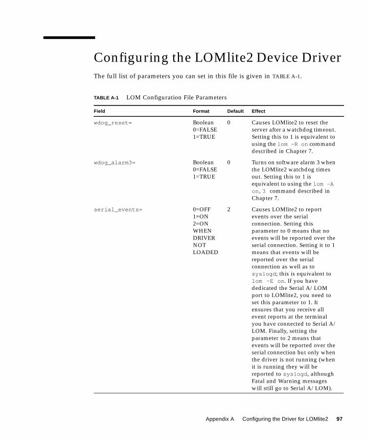
Configuring the LOMlite2 Device Driver
The full list of parameters you can set in this file is given in TABLE A-1.
TABLE A-1 LOM Configuration File Parameters
Field Format Default Effect
wdog_reset= Boolean
0=FALSE
1=TRUE
0 Causes LOMlite2 to reset the
server after a watchdog timeout.
Setting this to 1 is equivalent to
using the lom -R on command
described in Chapter 7.
wdog_alarm3= Boolean
0=FALSE
1=TRUE
0 Turns on software alarm 3 when
the LOMlite2 watchdog times
out. Setting this to 1 is
equivalent to using the lom -Aon,3 command described in
Chapter 7.
serial_events= 0=OFF
1=ON
2=ON
WHEN
DRIVER
NOT
LOADED
2 Causes LOMlite2 to report
events over the serial
connection. Setting this
parameter to 0 means that no
events will be reported over the
serial connection. Setting it to 1
means that events will be
reported over the serial
connection as well as to
syslogd ; this is equivalent to
lom -E on . If you have
dedicated the Serial A/LOM
port to LOMlite2, you need to
set this parameter to 1. It
ensures that you receive all
event reports at the terminal
you have connected to Serial A/
LOM. Finally, setting the
parameter to 2 means that
events will be reported over the
serial connection but only when
the driver is not running (when
it is running they will be
reported to syslogd , although
Fatal and Warning messages
will still go to Serial A/LOM).
Appendix A Configuring the Driver for LOMlite2 97

disable_wdog_on_break= Boolean
0=FALSE
1=TRUE
1 Causes LOMlite2 to disable its
watchdog if it detects a break
signal on the Serial A/LOM
port.
disable_wdog_on_panic= Boolean
0=FALSE
1=TRUE
1 Causes LOMlite2 to try to
disable its watchdog after a
system “panic”.
faulty_voltage_shutdown= Boolean
0=FALSE
1=TRUE
1 Causes LOMlite2 to attempt
first to shut down the system
and, if that fails, to power off
the system in the event of a
problem with the supply rails.
enclosure_warning_temp= oC 67 Specifies the temperature at
which LOMlite2 generates an
overtemperature event.
over_temperature_shutdown= Boolean
0=FALSE
1=TRUE
1 Causes LOMlite2 to attempt to
shut down the system, or to
power it off, if the enclosure
temperature exceeds the level
specified for the
enclosure_shutdown_temp
parameter.
enclosure_shutdown_temp= oC 72 Specifies the enclosure
temperature above which
LOMlite2 attempts to shut the
system down or, if this fails, to
power the system off. (LOMlite2
will attempt to do either of
these if
over_temperature_shutdown is
set to 1.)
serial_security= Boolean
0=FALSE
1=TRUE
1 Enables and disables the user
security facilities even if user
security has been configured.
You can use this parameter to
set up users again if your users
have forgotten their passwords.
TABLE A-1 LOM Configuration File Parameters (Continued)
Field Format Default Effect
98 Netra X1 Server User’s Guide • December 2000

Each parameter must be on a separate line and must be followed by an equals sign
(=) and a value, without spaces. Where the format is Boolean, 1 means true and 0
means false.
serial_timeout= Multiples
of 4 secs
0 Specifies the period after which
LOMlite2 gives control of the
Serial A/LOM port back to the
console when it has finished
sending a report (or when the
user has issued a LOMlite2 shell
command, if you have enabled
the serial_return= option). By
default, there is no delay at all.
serial_return= Boolean
0=FALSE
1=TRUE
0 Causes LOMlite2 to return the
user to the console from the
lom> prompt after each
LOMlite2 shell command. You
can use this option in
conjunction with the
serial_timeout= option.
reporting_level= Number
between 0
and 4
3 Indicates the severity level
down to which you want to see
LOMlite2 event reports. 0
means no reports. 1 means fatal
event reports only. 2 means fatal
and warning event reports. 3
means fatal, warning and
information event reports. 4
means fatal, warning,
information and user event
reports. (User event reports
concern the user security
facility; you will not see any
unless you have enabled the
security facility and set up
users.)
TABLE A-1 LOM Configuration File Parameters (Continued)
Field Format Default Effect
Appendix A Configuring the Driver for LOMlite2 99

100 Netra X1 Server User’s Guide • December 2000

Index
Aacoustic noise, 5
alarms, setting, 54, 67
altitude, 4
anti-static wrist strap, 84
Asynchronous Breakout Cable (Cisco), 19
automatic server restart, 61, 64 to 66
Bback panel LEDs, 78
BTU rating, 8
Ccabling, 16
Cisco L2511 Terminal Server, connecting, 18
configuration, 24
cooling (heat dissipation), 9
cross-over (null modem) cable, 20, 21
current
in-rush, 8
operating, 8
DDB25 adapter, 20
DB9 adapter, 21
domain name, 27
dumb terminal, serial connection, 18
Eelectro-magnetic compatibility, 5
Ethernet
connection, 27
LEDs, 79
ports, 2
event log, viewing, 43
Ffans, 56
checking the status, 59
location, 87
fault LED, 53, 78
turning on, 55
flooring, 5
front panel LEDs, 78
Hhard disk drive, 2
installing and removing, 89
location, 87
part number, 4
power and data cables, 91
heat dissipation, 9
host name, 27
displaying, 55
Iinput voltage range, 8
Index-101

in-rush current, 8
installation
alternative bracket arrangements, 13
mounting brackets, 12
rack mounting, 11
internal circuit breakers, 59
LLEDs
back panel, 79
Ethernet port indicators, 79
fault indicator, 78
front panel, 78
power indicator, 78
Lights Out Management (LOM)
commands, 54
displaying the host name, 55
displaying the version number of the LOM
device, 55
monitoring the system, 58 to 63
online documentation, 58
parameters, 97
power supply unit, 58
powering up the system, 55
restarting the system after a lockup, 64
returning control of serial connection to
console, 55
sample Event Log, 63
setting the alarms, 54, 67
setting up named users, 46 to 50
stopping event reporting, 97
turning the fault LED on, 55
updating component status, 54
viewing the LOM’s Event Log, 43
locating system components, 81
log, viewing, 43
LOMlite2 device
configuration variables, 50
removing driver protection, 69
separating from the console on Serial A, 52
sharing Serial A between the console and the
LOMlite2 device, 53
upgrading firmware, 70
version number, 55
LOMlite2 interface
backwards compatibility, 70
escape sequence, 68
Mmemory
configurations, 2
installing and removing, 88
location, 87
part number, 4
modem connection, 18, 21
interruption on Serial A port, 18
monitoring the system, See Lights-Out Management
(LOM)
NName Server, 27
Netmask, 28
null modem cable, 20, 21
OOn/Standby switch, 30
operating current, 8
optional components, 4
Pphysical specifications, 3
pinout
serial port, 18, 20
power
consumption, 9
factor, 8
requirements, 8, 9
switch, 30, 37
warnings, 17
power LED, 78
power supply
monitoring PSU and fans, 42
power supply unit, 58
location, 87
powering on, 30
problems
accessing the server from the console, 75
booting (OBP initialization aborts), 75
displaying the lom> prompt or the Solaris
prompt, 75
getting to the LOM prompt, 74
Index-102

receiving clearly formatted LOMlite2 output, 74
receiving text at the console on Serial
A/LOM, 75
reprogramming the LOMlite2 device, 74
setting up a console connection, 74
turning serial event reporting on and off, 74
Rrackmounting, 12
remote reset, 39
removal
hard disk drives, 89
memory, 88
system top cover, 90
replacing the server, 82
resetting remotely, 39
restart after lockup, 64
Ssafety, 5
SCC (system configuration card), 82
security, 5
LOMlite2 named user accounts, 46 to 50
Serial A/LOM port, 18
data subject to interruption by LOMlite2, 68
serial A/LOM port, 25, 27, 28
dedicating to the LOMlite2 device, 52
stopping event reporting to, 68
stopping event reports being sent to, 51
serial connection, 18, 22, 27, 28
returning control to console, 55
serial port, 2
connection settings, 22
DB25 adapter, 20
DB9 adapter, 21
pinout, 18, 20
shipkit, contents, 3
Solaris 8, 36, 57
specifications
features, 2
standby power, 8
stopping event reporting, 68
supply rail voltages, 59
system board, location of, 87
system configuration card (SCC)
swapping between servers, 82
system restart, 64
Ttemperature
checking the system’s temperature, 60
terminal server, 18
serial connection, 18
setting up the server using a terminal server, 24
thermal issues, 5
tip session, 20
top cover
removing, 85
replacing, 86
Vvoltage
frequency range, 8
input range, 8
volt-ampere rating, 8
Wwatchdog timeouts, 97
wrist strap, 84
Index-103