Embed Size (px)
Citation preview

����������������
��
�����������������������
��������
Publication: 9 2794 00 990Revision: A 01/98
Provided by N
ortheast Pow
er System
s, Inc. w
ww
.nepsi.com

i
W A R N I N G !To avoid personal injury or equipment damage, onlyqualified personnel should perform the procedurespresented in this manual.
������������
This Instruction Manual provides information concerning theoperation and installation of the BE1-59NC Neutral Overvoltage Relay.To accomplish this, the following is provided.
� Specifications
� Functional characteristics
� Mounting Information
� Connections
� Testing
REV A
ECA 14472
Provided by N
ortheast Pow
er System
s, Inc. w
ww
.nepsi.com

ii
CONFIDENTIAL INFORMATION
OF BASLER ELECTRIC COMPANY, HIGHLAND, IL. IT IS LOANED FORCONFIDENTIAL USE, SUBJECT TO RETURN ON REQUEST, AND WITH THEMUTUAL UNDERSTANDING THAT IT WILL NOT BE USED IN ANY MANNERDETRIMENTAL TO THE INTEREST OF BASLER ELECTRIC COMPANY.
First Printing: April 1994
Printed in USA
September 1994
It is not the intention of this manual to cover all details and variationsin equipment, nor does this manual provide data for every possiblecontingency regarding installation or operation. The availability anddesign of all features and options are subject to modification withoutnotice. Should further information be required, contact BaslerElectric Company, Highland, Illinois.
BASLER ELECTRIC, BOX 269 HIGHLAND, IL 62249 USA
PHONE 618-654-2341 FAX 618-654-2351
Provided by N
ortheast Pow
er System
s, Inc. w
ww
.nepsi.com

Provided by N
ortheast Pow
er System
s, Inc. w
ww
.nepsi.com
iii
������
Section 1 GENERAL INFORMATION 1-1
General . . . . . . . . . . . . . . . . . . . . . . . . . . . . . . . . . . . . . . . . . . . . . . . . 1-1Application . . . . . . . . . . . . . . . . . . . . . . . . . . . . . . . . . . . . . . . . . . . . . . 1-1
Capacitor Bank Switching . . . . . . . . . . . . . . . . . . . . . . . . . . . . . . . 1-1Protection . . . . . . . . . . . . . . . . . . . . . . . . . . . . . . . . . . . . . . . . . . . 1-1Input Sensing . . . . . . . . . . . . . . . . . . . . . . . . . . . . . . . . . . . . . . . . 1-2Alarms And Outputs . . . . . . . . . . . . . . . . . . . . . . . . . . . . . . . . . . . 1-3
Model and Style Number Description . . . . . . . . . . . . . . . . . . . . . . . . . 1-3Sample Style Number . . . . . . . . . . . . . . . . . . . . . . . . . . . . . . . . . . 1-3Style Number Identification Chart . . . . . . . . . . . . . . . . . . . . . . . . . 1-4
Specifications . . . . . . . . . . . . . . . . . . . . . . . . . . . . . . . . . . . . . . . . . . . 1-4Characteristic Curves . . . . . . . . . . . . . . . . . . . . . . . . . . . . . . . . . . . . . 1-6
Section 2 CONTROLS AND INDICATORS 2-1
Section 3 FUNCTIONAL DESCRIPTION 3-1
General . . . . . . . . . . . . . . . . . . . . . . . . . . . . . . . . . . . . . . . . . . . . . . . . 3-1Functional Description . . . . . . . . . . . . . . . . . . . . . . . . . . . . . . . . . . . . . 3-1
Inputs . . . . . . . . . . . . . . . . . . . . . . . . . . . . . . . . . . . . . . . . . . . . . . 3-1Filters . . . . . . . . . . . . . . . . . . . . . . . . . . . . . . . . . . . . . . . . . . . . . . 3-1Overvoltage Comparator . . . . . . . . . . . . . . . . . . . . . . . . . . . . . . . . 3-2Definite Time Delay . . . . . . . . . . . . . . . . . . . . . . . . . . . . . . . . . . . 3-2Inverse Time Delay . . . . . . . . . . . . . . . . . . . . . . . . . . . . . . . . . . . . 3-2Reference voltage Circuit . . . . . . . . . . . . . . . . . . . . . . . . . . . . . . . 3-2Power Supply . . . . . . . . . . . . . . . . . . . . . . . . . . . . . . . . . . . . . . . . 3-2Power Supply Status Contacts . . . . . . . . . . . . . . . . . . . . . . . . . . . 3-2Target Indicator Circuits . . . . . . . . . . . . . . . . . . . . . . . . . . . . . . . . 3-2
Section 4 INSTALLATION 4-1
General . . . . . . . . . . . . . . . . . . . . . . . . . . . . . . . . . . . . . . . . . . . . . . . . 4-1Relay Operating Precautions . . . . . . . . . . . . . . . . . . . . . . . . . . . . . . . 4-1Dielectric Test . . . . . . . . . . . . . . . . . . . . . . . . . . . . . . . . . . . . . . . . . . . 4-1Relay Mounting . . . . . . . . . . . . . . . . . . . . . . . . . . . . . . . . . . . . . . . . . . 4-1Connections . . . . . . . . . . . . . . . . . . . . . . . . . . . . . . . . . . . . . . . . . . . . 4-8
Section 5 TESTING 5-1
General . . . . . . . . . . . . . . . . . . . . . . . . . . . . . . . . . . . . . . . . . . . . . . . . 5-1Equipment Required . . . . . . . . . . . . . . . . . . . . . . . . . . . . . . . . . . . . . . 5-1Operational Test . . . . . . . . . . . . . . . . . . . . . . . . . . . . . . . . . . . . . . . . . 5-1
E2 Timing Option . . . . . . . . . . . . . . . . . . . . . . . . . . . . . . . . . . . . . 5-1Typical Test Setup Timing Option E2 . . . . . . . . . . . . . . . . . . . . . . 5-2Typical Test Setup Timing Option D1 Or D2 . . . . . . . . . . . . . . . . . 5-3D1 Timing Option . . . . . . . . . . . . . . . . . . . . . . . . . . . . . . . . . . . . . 5-4D2 Timing Option . . . . . . . . . . . . . . . . . . . . . . . . . . . . . . . . . . . . . 5-6

iv
CONTENTS - Continued
Section 6 MAINTENANCE 6-1
General . . . . . . . . . . . . . . . . . . . . . . . . . . . . . . . . . . . . . . . . . . . . . . . . 6-1Storage . . . . . . . . . . . . . . . . . . . . . . . . . . . . . . . . . . . . . . . . . . . . . . . . 6-1Test Plug . . . . . . . . . . . . . . . . . . . . . . . . . . . . . . . . . . . . . . . . . . . . . . . 6-1
Section 7 MANUAL CHANGE INFORMATION 7-1
Provided by N
ortheast Pow
er System
s, Inc. w
ww
.nepsi.com

1-1
��������
GENERAL INFORMATION
GENERAL
BE1-59NC Neutral Overvoltage Relays provide sensitive protection for capacitor banks. There are threecommon types of capacitor bank failures that BE1-59NC Neutral Overvoltage Relays recognize. They are:
� Unit dielectric failure.� Capacitor bank insulator failure.� Blown fuses.
BE1-59NC Neutral Overvoltage Relays protect for overvoltages due to internal voltage shifts that occur asa result of these types of failures.
APPLICATION
Capacitor banks are widely used by utilities to maintain specified system voltage. Addition of capacitiveloads at appropriate points on the system compensate for heavy inductive loading that normally tends toreduce voltage. This adding of leading megavars to compensate for the lagging megavar component ofelectric loads is frequently referred to as power factor correction. Capacitor banks must be switched inresponse to actual load conditions in order to obtain maximum power factor correction benefits.
Capacitor Bank Switching
One of the common methods of maximizing capacitor bank benefits is by evaluating the bus voltage. Abandwidth surrounding the desired bus voltage level is established. When the bus voltage falls below thebandwidth level, the capacitor bank is switched into the circuit. When the bus voltage rises above thebandwidth level, the capacitor bank is switched out.
Protection
Protection of capacitor banks has always been difficult. It is especially difficult to sense failures inside thecapacitor banks because of the configuration. Experience indicates that most capacitor bank faults involveone or more insulator failures with arcing across groups and/or phase-to-phase inside the bank. In mostcases, these types of faults are not seen by the bus differential or other protection unless the arcing spillsover to the area between the fuses and the circuit switcher. A fault across an insulator usually means thatone or more groups of parallel units are shorted. This will cause a neutral shift and unbalanced phasecurrents. Unbalanced phase current magnitudes are determined by the number of series connected groups.For full phase-to-neutral flashover, the maximum phase current is three times normal capacitor bank loadin the faulted phase.
One main protection concern is overvoltage cascading. A capacitor bank is unique in that cascading of unitsmay take place after a predetermined number of unit fuses have operated. Normally after a fuse has blownin any other type of equipment, the faulted apparatus is disconnected and usually does not affect anyremaining equipment that is in service. That is not so with a capacitor bank. Each fuse that blows to isolatethe faulted unit sets up an increased voltage stress on the remaining units (Figure 1-1). Sometime later, thenext weakest unit in that group fails. As each successive fuse blows, the voltage increases another step andrapidly causes the next unit to fail. Cascading takes place and results in serious damage to the capacitorbank and possible hazards to personnel. While the capacitor bank is failing, the station in minimally affected.
Provided by N
ortheast Pow
er System
s, Inc. w
ww
.nepsi.com

BE1-59NC General Information
1-2
The voltage is nearly normal, the current flow is almost unaffected, and station relay protection is not takingany action until the failure has developed into a phase-to-phase or phase-to-ground fault.
A solution was to develop a protective scheme for the capacitor bank with the main emphasis on preventingovervoltage cascading. To do this, a ground fault relay or neutral shift device had to be developed that wassensitive enough to detect blown fuses for both alarming and tripping purposes. The best place to obtainthe sensing information is between the neutral of the capacitor bank and ground. Voltage differentialsbetween the normal capacitor bank status and that of one blown fuse are very small. However, BE1-59NCNeutral Overvoltage Relays are sensitive enough to differentiate between these conditions and actdecisively.
Figure 1-1. Ungrounded 3-Phase, 3-Wire System
Input Sensing
BE1-59NC Neutral Overvoltage Relays receive the input signal from voltage sensing devices connectedbetween the capacitor bank neutral and ground. These voltage sensing devices can be potentialtransformers or resistor potential devices. Ideally, the voltage across each leg of a capacitor bank isbalanced, and the voltage from neutral to ground is zero. If a single capacitor fails and blows the protectingfuse, an unbalanced condition occurs that shifts the neutral and creates a small but measurable voltage.Through the potential sensing devices, the neutral relay senses this voltage unbalance and reacts to givethe appropriate signal (usually an alarm or trip depending on the voltage level).
Further loss of more capacitors increases the neutral voltage. The relay senses this voltage increase, andreacts to give the appropriate signal. This signal is usually a trip depending on the voltage levels and howthe protection scheme is designed.
Provided by N
ortheast Pow
er System
s, Inc. w
ww
.nepsi.com

BE1-59NC General Information
1-3
Alarms And Outputs
Sensitive settings on the relay are used as an alarm to alert that a fuse has blown and maintenance isrequired. They would be typically set at a level corresponding to the voltage rise caused by one blown fuse.The second output would have a setting that would be set to trip the capacitor bank off the bus or line whenthe voltage exceeds 110% of the nominal capacitor bank voltage. This setting depends on the capacitorbank size and configuration.
MODEL AND STYLE NUMBER DESCRIPTION
BE1-59NC Neutral Overvoltage Relays electrical characteristics and operational features are defined by acombination of letters and numbers that make up the style number. Model numbers BE1-59NC designatethe relay as a Basler Electric, Class 100, Relay. The model number, together with the style number,describe the options included in a specific device, and appear on the front panel, drawout cradle, and insidethe case assembly. Upon receipt of a relay, be sure to check the style number against the requisition andthe packing list to ensure that they agree.
Sample Style Number
Style number identification chart (Figure 1-2) defines the electrical characteristics and operational featuresincluded in BE1-59NC Neutral Overvoltage Relays. For example, if the model number of the relay was BE1-59NC, and the style number was A5E-E2J-C0S1F, the device would have the following features:
A - Single-phase voltage5 - 120 Vac, 60 Hz, nominal 1 to 20 Vac pickupE - Two output relays with normally open contactsE2 - Two setpoints; setpoint 1, definite timing 00.0 to 99.9 seconds; setpoint 2, definite timing
00.0 to 99.9 secondsJ - 125 Vdc or 100/120 Vac power supplyC - Internally operated targetsO - NoneS - Push-to-energize outputs1 - Two auxiliary output relays, two SPDT sets of contacts; one for setpoint 1 and one for
setpoint 2F - Semi-flush mounting case
Provided by N
ortheast Pow
er System
s, Inc. w
ww
.nepsi.com

BE1-59NC General Information
1-4
Figure 1-2. Style Number Identification Chart
SPECIFICATIONS
BE1-59NC Neutral Overvoltage Relays have the following features and capabilities.
Voltage Sensing Inputs Maximum continuous rating: 360 Vac for 100/120 Vac input, 480 Vac for200/240 Vac input, with a maximum burden of 2 VA.
Sensing Input RangesRanges 1 and 5 1 to 20 Vac pickupRanges 2 and 6 10 to 50 Vac pickupRanges 3 and 7 2 to 40 Vac pickupRanges 4 and 8 20 to 100 Vac pickup
Provided by N
ortheast Pow
er System
s, Inc. w
ww
.nepsi.com

BE1-59NC General Information
1-5
Pickup AccuracyRanges 1, 3, 5, or 7 ±2.0% or 100 millivolts, whichever is greater.Ranges 2, 4, 6, or 8 ±2.0% or 200 millivolts, whichever is greater.
Dropout 98% of pickup within 7 cycles.
Timing CharacteristicsInverse Response time decreases as the difference between the monitored voltage
and the setpoint increases. The inverse time characteristics switch isadjustable from 01 to 99 in 01 increments. Each position corresponds toa specific curve except 00, which is instantaneous.
Definite Adjustable from 00.1 to 99.9 seconds, in steps of 0.1 seconds. Accuracyis within 2.0 % or 100 milliseconds, whichever is greater. (A setting of 00.0provides instantaneous timing.)
Accuracy Within ±5% or 25.0 milliseconds (whichever is greater) of the indicated timefor any combination of the time dial and within ±2% of the voltagemagnitude or 100 millivolts (for the 100/120 Vac sensing ranges) or 200millivolts (for the 200/240 Vac sensing ranges) (whichever is greater) fromthe actual pickup value. Inverse time is repeatable within ±2% or 25.0milliseconds (whichever is greater) for any time dial or pickup setting.
Power Supply Refer to Table 1-1.
Table 1-1. Power Supply Specifications.
TypeNominal
InputVoltage
InputVoltageRange
Burdenat
Nominal
J 125 Vdc120 Vac
62 to 150 Vdc90 to 132 Vac
7.5 W15.0 W
K 48 Vdc 24 to 60 Vdc 7.0 W
†L 24 Vdc 12 to 32 Vdc 7.5 W
‡Y 48 Vdc125 Vdc
24 to 60 Vdc62 to 150 Vdc
7.0 W7.5 W
Z 250 Vdc230 Vac
140 to 280 Vdc190 to 270 Vac
12.0 W33.5 VA
NOTES:† Type L Power Supply may require 14 Vdc to begin operation.
Once operating, the voltage may be reduced to 12 Vdc.‡ Type Y Power Supply is field selectable for 48 or 125 Vdc.
Selection must be implemented at time of installation. This PowerSupply option is factory set for 125 Vdc.
Output Contacts Output contacts are rated as follows:Resistive:
120/240 Vac Make 30 A for 0.2 seconds, carry 7 A continuously, and break 7 A.
250 Vdc Make and carry 30 A for 0.2 seconds, carry 7 A continuously, and break0.3 A.
500 Vdc Make and carry 15 A for 0.2 seconds, carry 7 A continuously, and break
Provided by N
ortheast Pow
er System
s, Inc. w
ww
.nepsi.com

BE1-59NC General Information
1-6
0.1 A.
Output Contacts - ContinuedInductive:
120/240 Vac, Make and carry 30 A for 0.2 seconds, carry 7 A continuously, and break125/250 Vdc 0.3 A. (L/R = 0.04).
Target Indicators Targets indicators are operated by a minimum of 0.2 A through the outputtrip circuit. The output circuit must be limited to 30 A for 0.2 seconds, 7 Afor 2 minutes, and 3 A continuously. Target coil resistance is 0.1 ohm.
Isolation 1500 Vac at 60 hertz for one minute in accordance with IEC 255-5 andANSI/IEEE C37.90-1989 (Dielectric Test).
Radio Frequency Field Tested using a five watt, hand-held transceiver operating at randomInterference (RFI) frequencies centered around 144 MHz and 440 MHz, with the antenna
located six inches from the relay in both horizontal and vertical planes.
Surge Withstand Capability Qualified to ANSI/IEEE C37.90.1-1989 Standard Surge Withstand Capabil-ity (SWC) Tests for Protective Relays and Relay Systems.
Operating Temperature -40�C (-40�F) to +70�C (+158�F).
Storage Temperature -65�C (-85�F) to +100�C (+212�F).
Shock In standard tests, the relay has withstood 15 g in each of three mutuallyperpendicular planes without structural damage or degradation of perfor-mance.
Vibration: In standard tests, the relay has withstood 2 g in each of three mutually per-pendicular planes, swept over the range of 10 to 500 Hz for a total of sixsweeps, 15 minutes each sweep, without structural damage or degradationof performance.
Weight 13.6 pounds maximum.
Case Size S1.
CHARACTERISTIC CURVES
Figures 1-3 (drawing number 99-1510) and 1-4 (drawing number 99-1545) illustrate the overvoltage inversetime curves for this relay. To order a full-size drawing on transparent paper (vellum) of these characteristiccurves, contact Customer Service Department of the Power Systems Group, Basler Electric, and requestthe appropriate drawing number.
Provided by N
ortheast Pow
er System
s, Inc. w
ww
.nepsi.com

BE1-59NC General Information
1-7
Figure 1-3. Overvoltage Inverse Time Curves, Low Ranges(Drawing Number 99-1510)
.. 20
•• • Vl • C> 7 z • 8 . w • Vl
~ J
w 2 :::;; >=
' •• .. ·' .• .. .. .J
.2
·" .~ ~
' " ·"'-
"'
~
" ~ ......... ~
........ ..... --r-.. ......... r--
' ........ I"'-, ....... ~
.......... r-I-.
-2 3 4 5 6 7 8 9 10 II
4 6 8 10 12 14 16 18 20 22
VOLTAGE DIFFERENCE FROM PICKUP
& SENSING INPUT RANGES 1 8c 5
~ SENSING INPUT RANGES .3 8c 7
12 13 14 15
24 26 28 30
T I M E
D I A L
99 80 60 50 40 .30
20
10 07 05 0.3 02 01
16
32
01851-02 9-1-94
Provided by N
ortheast Pow
er System
s, Inc. w
ww
.nepsi.com

BE1-59NC General Information
1-8
Figure 1-4. Overvoltage Inverse Time Curves, High Ranges(Drawing Number 99-1545)
.. 20
10 • (f) • 0 7 z • 0 • u w • (f)
;;; 3
w 2 :::;; >=
' •• .. ·' .• .. .. ...
·'
·'
\."-
\. "" &: ~
~
"' ....... ..... r--... -"' r-... ....... r--·'- 1'.. ........ r-
"' "'-" r-.... r-r-
r.....
2 4 6 7 8 9 10 II
4
3
6 8 w 12 14 ~ 18 ~ ~
VOLTAGE DIFFERENCE FROM PICKUP
& SENSING INPUT RANGES 2 It 6
.& SENSING INPUT RANGES 4 It 8
12 13 14 15
24 26 28 30
T I M E D I
A L
99 BD 60 50 40 .3D
20
10 07 05 0.3 02 01
16
32
D195J-07 Sl-1-14
Provided by N
ortheast Pow
er System
s, Inc. w
ww
.nepsi.com

Provided by N
ortheast Pow
er System
s, Inc. w
ww
.nepsi.com
2-1
��������
CONTROLS AND INDICATORS
GENERAL
Table 2-1 lists and describes the controls and indicators of BE1-59NC Ground Fault Overcurrent Relays.
Table 2-1. Controls and Indicators (Refer to Figure 2-1)
Letter Control or Indicator Function or Indicator
A OVERVOLTAGE 1 PICKUPAdjustment
A multiturn potentiometer that sets the overvoltagecomparator threshold voltage. Continuously adjustable forthe sensing input voltage range.
B OVERVOLTAGE 1 PICKUPLED
A red LED that lites when overvoltage exceeds the pickupsetting.
C OVERVOLTAGE 1 TIMEDIAL
Thumbwheel switch that selects the desired overvoltageoutput delay (inverse time characteristic curves 01 through99). A setting of 00 is instantaneous.
D OVERVOLTAGE 2 TIMEDIAL
Thumbwheel switch that selects the desired overvoltageoutput delay (definite timing characteristic adjustable from00.1 to 99.9 seconds, in 0.1 second increments). A settingof 00 is instantaneous.
E POWER LED LED lites to indicate that the relay power supply isfunctioning.
F Target Reset Lever Linkage extending through bottom of front cover that resetsmagnetically latching target indicators.
G Target Indicators Magnetically latching targets that indicate that trip current inexcess of 0.2 A was present and that the associated outputrelay has been energized.
H PUSH TO ENERGIZEOUTPUT Switches
Momentary pushbutton switches accessible by inserting a1/8 inch diameter non-conducting rod through the frontpanel. Pushbuttons are used to energize the output relaysto test external system wiring. If current flows in externallyoperated target trip circuits, the targets drop.
I OVERVOLTAGE 2 PICKUPLED
A red LED that lites when overvoltage exceeds the pickupsetting.
J OVERVOLTAGE 2 PICKUPAdjustment
A multiturn potentiometer that sets the overvoltagecomparator threshold voltage. Continuously adjustable forthe sensing input voltage range.

BE1-59NC Controls and Indicators
2-2
Figure 2-1. Location of Controls and Indicators.
J}-+----~
~ Basler Electric :;)®Highland, Illinois
SOLID STATE PROTECTIVE RELAY
BE1-59NC NEUTRAL OVERVOLTAGE
H OVER OVER
PUSH TO ENERGIZE OUTPUT
O~RQ
0'1'R Q
1 2
-- A1E-E2J-COS1F
01481-05 OJ-03-9-'
Provided by N
ortheast Pow
er System
s, Inc. w
ww
.nepsi.com

Provided by N
ortheast Pow
er System
s, Inc. w
ww
.nepsi.com
3-1
��������
FUNCTIONAL DESCRIPTION
GENERAL
BE1-59NC Neutral Overvoltage Relays are solid state digital devices that detect ground faults andneutral overvoltages. Figure 3-1 illustrates the overall operation of the relay and the followingparagraphs describe the functional description.
Figure 3-1. Functional Block Diagram
FUNCTIONAL DESCRIPTION
Inputs
Sensed voltage developed across the input sensing device connected in the neutral-grounding currenttransformer secondary is applied to the BE1-59NC Neutral Overvoltage Relay. Internal transformersprovide further isolation and step down for the relay logic circuits. BE1-59NC Neutral OvervoltageRelays may also be used in ungrounded systems with voltage transformers connected in wye/brokendelta configurations. Typical connection methods are shown in Section 4. Overvoltage #1 andOvervoltage #2 circuits are functionally the same except for timing characteristics.
Filters
Bandpass filters provide peak sensitivity at 50 or 60 hertz for the overvoltage #1 and overvoltage #2inputs. Third harmonic rejection is 40 dB minimum.

BE1-59NC Functional Description
3-2
Overvoltage Comparator
Each overvoltage comparator circuit receives a sensing voltage from the bandpass filter and a referencevoltage from the front panel setting. When the input exceeds the setting reference, the comparatoroutput enables the timing circuit and the OVERVOLTAGE PICKUP LED turns ON.
Definite Time Delay
An output signal from the comparator circuit enables a counting circuit to be incremented by an internalclock. When the counting circuit reaches the count that matches the number entered on the TIME DIAL,the output relay and auxiliary relay are energized. However, if the sensed input voltage falls below thepickup setting before the timer completes its cycle, the timer resets within 2.0 cycles.
The definite time delay is adjustable from 00.1 to 99.9 seconds in 0.1 second increments. Front panelmounted switches determine the delay. Position 00.0 is instantaneous.
Inverse Time Delay
Inverse time delay circuits are identical to definite time delay circuits except that a voltage controlledoscillator (VCO) is substituted for the clock signal. The VCO is controlled by a voltage derived from thesensed input. Because the frequency of the oscillator is kept proportional to the sensed input voltage,the desired inverse time delay is produced.
Inverse time characteristic curve thumbwheel switches are setable from 01 to 99 in 01 increments. Eachposition corresponds to a specific curve setting except 00, which is instantaneous. Refer to Figures 1-3and 1-4 to see the inverse time characteristic curves.
Reference Voltage Circuit
A constant voltage source provides a reference voltage to the potentiometers on the front panel. Thepotentiometers, in turn, provide reference voltages to all the comparator circuits and establish thethreshold for each circuit.
Power Supply
The solid-state power supply is a low burden, flyback switching design that delivers a nominal plus orminus twelve volts dc to the internal circuitry. Power supply inputs are not polarity sensitive. A red LEDlites to indicate that the power supply is functioning properly.
Power Supply Status Contacts
Power supply output contacts are monitored at the mother board. Normal supply voltage causes thestatus relay to be continually energized. However, if at any time the voltage falls below requirements,the relay drops out, and closes the normally closed contacts.
Target Indicator Circuits
A front panel target indicator is provided for each overvoltage element. These targets operate only whena minimum of 0.2 amperes flows in the output circuit. A special reed relay in series with the outputcontact provides the signal to the target indicator. Each target, when operated, is magnetically latchedand must be reset manually.
Provided by N
ortheast Pow
er System
s, Inc. w
ww
.nepsi.com

Provided by N
ortheast Pow
er System
s, Inc. w
ww
.nepsi.com
4-1
��������
INSTALLATION
GENERAL
When not shipped as part of a control or switchgear panel, the relays are shipped in sturdy cartons toprevent damage during transit. Immediately upon receipt of a relay, check the model and style numberagainst the requisition and packing list to see that they agree. Visually inspect the relay for damage thatmay have occurred during shipment. If there is evidence of damage, immediately file a claim with thecarrier and notify the Regional Sales Office, or contact the Sales Representative at Basler Electric,Highland, Illinois.
In the event the relay is not to be installed immediately, store the relay in its original shipping carton in amoisture and dust free environment. When relay is to be placed in service, it is recommended that theoperational test procedure (Secton 5) be performed prior to installation.
RELAY OPERATING PRECAUTIONS
Before installation or operation of the relay, note the following precautions:
1. A minimum of 0.2 A in the output circuit is required to ensure operation of current operatedtargets.
2. Do not touch target indicator vanes. Always reset targets by use of the target reset lever.
3. The relay is a solid-state device. If a wiring insulation test is required, remove the connectionplugs and withdraw the cradle from its case.
4. When the connection plugs are removed, the relay is disconnected from the operating circuit andwill not provide system protection. Always be sure that external operating (monitored) conditionsare stable before removing a relay for inspection, test, or service.
5. Be sure the relay case is hard wired to earth ground using the ground terminal on the rear of theunit. It is recommended to use a separate ground lead to the ground bus for each relay.
DIELECTRIC TEST
In accordance with IEC 255-5 and ANSI/IEEE C37.90-1978, one-minute dielectric (high potential) testsup to 1500 Vac (45-65 hertz) may be performed. This device employs decoupling capacitors to groundfrom the input and output terminals. Leakage current of less than 5 milliamperes is to be expected at thegrouped power supply inputs or sensing inputs and less than 20 milliamperes at the outputs.
RELAY MOUNTING
Because the relay is of solid state design, it does not have to be mounted vertically. Any convenientmounting angle may be chosen. Figures 4-1 through 4-13 provide relay outline dimensions and paneldrilling diagrams.

BE1-59NC Installation
4-2
Figure 4-1. S1 Case, Panel Drilling Diagram, Semi-Flush Mounting
Figure 4-2. S1 Case, Outline Dimensions, Front View
Provided by N
ortheast Pow
er System
s, Inc. w
ww
.nepsi.com

BE1-59NC Installation
4-3
Figure 4-3. S1 Case, Double-Ended, Semi-Flush Mounting, Side View
1.50 (38.1) j
~--"111
9.13 (231.9)
01427-27 7-9-93
6.19 (157.2)
4.03 (102.4)
4.03 (102.4)
.31 {7.9)
.75-J {19.1)
-.75 {19.1)
-
10-32 SCREWS
10-32 SCREWS
Provided by N
ortheast Pow
er System
s, Inc. w
ww
.nepsi.com

BE1-59NC Installation
4-4
Figure 4-4. S1 Case, Double-Ended, Semi-Flush Mounting, Outline Dimensions, Rear View
1------ 5.56 -----1 ( 141. 3) 01427-24
7-9-93
8.68 (220.7)
Provided by N
ortheast Pow
er System
s, Inc. w
ww
.nepsi.com
BE1-59NC Installation
4-5
Figure 4-5. S1 Case, Double-Ended, Projection Mounting, Panel Drilling Diagram, Rear View
~28 (108.7)
~28 {108.7}
3.20 (81.3)
3.20 (81.3)
.75 (19.1) DIA. 20 PLACES
·~-------- ~25 ----------1 ,- (133.4)
1--------- ~25 (1JJ.4}
+ 1
.69 (17.5)
I 1.47
(37.3)
j
01427-0!> 2-17-113
Provided by N
ortheast Pow
er System
s, Inc. w
ww
.nepsi.com

BE1-59NC Installation
4-6
Figure 4-6. S1 Case, Double-Ended, Projection Mounting, Rear View
1------ 5.56 -----1 ( 141. 3) 01427-02
7-9-93
8.68 (220.7)
Provided by N
ortheast Pow
er System
s, Inc. w
ww
.nepsi.com

BE1-59NC Installation
4-7
Figure 4-7. S1 Case, Double-Ended, Projection Mounting, Side View
9.13 (231.9)
01427-0J 7-9-93
4.03 (102.4)
4.03 {102.4)
.31 {7.9)
10-32 SCREWS
MOUNTING PANEL
5/16-18 STUD
2PLACES ~
.25 CASE_/ PANEL (6.4)
01427-118 1-~IIJ
DETAIL A A
SHOWING THE ADDITION OF WASHERS OVER THE BOSS TO TIGHTEN THE
RELAY AGAINST THE PANEL.
10-32 SCREWS
1~------!---~--lr-t--~ TERMINAL EXTENSION (TYP.) FOR DETAILED INSTRUCTIONS. SEE THE TERMINAL PROJECTION MOUNTING KIT SUPPLIED.
Provided by N
ortheast Pow
er System
s, Inc. w
ww
.nepsi.com

BE1-59NC Installation
4-8
NOTEBe sure the relay case is hard-wired to earth ground with no smaller than 12 AWGcopper wire attached to the ground terminal on the rear of the relay case. When therelay is configured in a system with other protective devices, it is recommended to usea separate lead to the ground bus from each relay.
CONNECTIONS
Incorrect wiring may result in damage to the relay. Except as noted previously, connections should bemade with minimum wire size of 14 AWG. Typical dc control circuit connections are shown in Figure 4-
8, and typical protection methods in Figure 4-9. Internal connections are shown in Figure 4-10.
Figure 4-8. Typical Control Circuit Connections
Provided by N
ortheast Pow
er System
s, Inc. w
ww
.nepsi.com

BE1-59NC Installation
4-9
Figure 4-9. Typical Protection Methods
014.32-1.3 .3-10-9.3
01432-14 03-03-94
86 ,------1.-t:---o 59NC
6 59NC
'---o-------6 59NC -7-
Provided by N
ortheast Pow
er System
s, Inc. w
ww
.nepsi.com

BE1-59NC Installation
4-10
Figure 4-10. Typical Internal Connections
EXlERNAL CASE
GROUND TERMINAL
2
#2 AUXILIARY
I 1 AUXILIARY
OVERVOLTAGE TRIP I 2
OVER VOLT AGE # 1 CIRCUITRY
POWER SUPPLY STATUS
OVER VOLT AGE # 2 CIRCUITRY
POWER SUPPLY
PADDLE OPERATED SHORTING BARS
OVERVOL TAGE I 1 TRIP
0983-026 03-08-94
Provided by N
ortheast Pow
er System
s, Inc. w
ww
.nepsi.com

Provided by N
ortheast Pow
er System
s, Inc.
5-1
��������
TESTING
GENERAL
Results obtained from these procedures may not fall within specified tolerance. When evaluatingresults, consideration should be given to the following prominent factors.
� Inherent error of the test equipment used.� Inherent inconsistency or repeatability of the testing method.� Tolerance level and accuracy of components used in the test setup.
EQUIPMENT REQUIRED
� Two Multi-Amp SSR-78 and a counter/timer accurate to at least 1.0% or one Doble F2500 (hastimer included) or suitable substitute.
� Digital voltmeter accurate to within 1% or better� Variable AC/DC (0-250V) power supply (for power input)� DC power supply (for current operated targets)
OPERATIONAL TEST
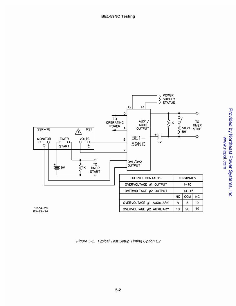
Step 1. Perform the appropriate test setup for your relay. Use Figure 5-1 for timing option E2 andFigure 5-2 for timing options D1 or D2. On D1, setpoint one is inverse time and setpoint twois definite time.
Step 2. Apply operating power to the relay, verify that the POWER LED is ON, and verify that thepower supply status contact is open.
Step 3. Perform the following timing tests as appropriate for your relay.
E2 Timing Option
Step 1. Reference to Figure 5-1, connect an ac voltage source (50 or 60 Hz, depending upon inputoption) to case terminals 6 and 7. Adjust this voltage to equal the desired overvoltage pickuplevel for OVERVOLTAGE 1.
Step 2. Starting at maximum CW, slowly turn OVERVOLTAGE 1 PICKUP ADJUST potentiometer R63CCW until OVERVOLTAGE 1 PICKUP LED just illuminates.
Step 3. Set OVERVOLTAGE 1 TIME DIAL to 001 and apply to case terminals 6 and 7, a voltage thatis 10% greater than the value applied in Step 1.
Step 4. Monitor the output terminals indicated in Figure 5-1 for OVERVOLTAGE 1. Remove, thenreapply the overvoltage at case terminals 6 and 7. Observe the time registered by thecounter. Time must equal the setting ±100 milliseconds or 2%, whichever is greater.
ww
w.nepsi.com
BE1-59NC Testing
5-2
Figure 5-1. Typical Test Setup Timing Option E2
Provided by N
ortheast Pow
er System
s, Inc. w
ww
.nepsi.com

BE1-59NC Testing
5-3
Figure 5-2. Typical Test Setup Timing Options D1 Or D2
Provided by N
ortheast Pow
er System
s, Inc. w
ww
.nepsi.com
BE1-59NC Testing
5-4
NOTEIn the following inverse time tests, voltage is stepped from one-half of pickup to avoltage that is higher (by value in column for Volts Over Pickup, Table 1) than thepickup.
E2 Timing Option - continued
Step 5. Set OVERVOLTAGE 1 TIME DIAL to 010. Monitor the output terminals indicated in Figure 1for OVERVOLTAGE 1. Remove, then reapply the overvoltage at case terminals 6 and 7. Observe the time registered by the counter. Time must equal the setting ±100 milliseconds or2%, whichever is greater.
Step 6. Set OVERVOLTAGE 1 TIME DIAL to 100. Monitor the output terminals indicated in Figure 1for OVERVOLTAGE 1. Remove, then reapply the overvoltage at case terminals 6 and 7. Observe the time registered by the counter. Time must equal the setting ±100 milliseconds or2%, whichever is greater.
Step 7. Set OVERVOLTAGE 1 TIME DIAL to 999. Monitor the output terminals indicated in Figure 1for OVERVOLTAGE 1. Remove, then reapply the overvoltage at case terminals 6 and 7. Observe the time registered by the counter. Time must equal the setting ±100 milliseconds or2%, whichever is greater.
Step 8. Adjust the voltage source to equal the desired overvoltage pickup level for OVERVOLTAGE 2.
Step 9. Starting at maximum CW, slowly turn OVERVOLTAGE 2 PICKUP ADJUST potentiometer R43CCW until OVERVOLTAGE 2 PICKUP LED just illuminates.
Step 10. Set OVERVOLTAGE 2 TIME DIAL to 001 and apply to case terminals 6 and 7, a voltage thatis 10% greater than the value applied in Step 1.
Step 11. Monitor the output terminals indicated in Figure 1 for OVERVOLTAGE 2. Remove, thenreapply the overvoltage at case terminals 6 and 7. Observe the time registered by thecounter. Time must equal the setting ±100 milliseconds or 2%, whichever is greater.
Step 12. Set OVERVOLTAGE 2 TIME DIAL to 010. Monitor the output terminals indicated in Figure 1for OVERVOLTAGE 2. Remove, then reapply the overvoltage at case terminals 6 and 7. Observe the time registered by the counter. Time must equal the setting ±100 milliseconds or2%, whichever is greater.
Step 13. Set OVERVOLTAGE 2 TIME DIAL to 100. Monitor the output terminals indicated in Figure 1for OVERVOLTAGE 2. Remove, then reapply the overvoltage at case terminals 6 and 7. Observe the time registered by the counter. Time must equal the setting ±100 milliseconds or2%, whichever is greater.
Step 14. Set OVERVOLTAGE 2 TIME DIAL to 999. Monitor the output terminals indicated in Figure 1for OVERVOLTAGE 2. Remove, then reapply the overvoltage at case terminals 6 and 7. Observe the time registered by the counter. Time must equal the setting ±100 milliseconds or2%, whichever is greater.
D1 Timing Option
Step 1. With reference to Figure 5-2, set PS1 for the value shown in Table 5-1, input option (column 1)and for the specific pickup voltage (column 2, Volts Pickup 50/60 Hz). Example: input option1, PS1 set to 10 volts, at 0�.
Provided by N
ortheast Pow
er System
s, Inc. w
ww
.nepsi.com

BE1-59NC Testing
5-5
Table 5-1. Inverse Time Overvoltage Levels And Delays For Input Options
Input Option (Style NO.2nd Digit)
VoltsPickup
50/60 Hz
PS150/60 HzVolts @ �
PS250/60 HzVolts @ �
VoltsOver
Pickup
TIME DIAL
11 33 55 88
1 10 5 @ 0� 13 @ 180� 8 0.612 1.545 2.478 3.876
2 30 15 @ 0� 23 @ 180� 8 0.582 1.534 2.487 3.916
3 21 10.5 @ 0� 26.5 @ 180� 16 0.612 1.545 2.478 3.876
4 60 30 @ 0� 46 @ 180� 16 0.582 1.534 2.487 3.916
5 10 5 @ 0� 13 @ 180� 8 0.612 1.545 2.478 3.876
6 30 15 @ 0� 23 @ 180� 8 0.582 1.534 2.487 3.916
7 21 10.5 @ 0� 26.5 @ 180� 16 0.612 1.545 2.478 3.876
8 60 30 @ 0� 46 @ 180� 16 0.582 1.534 2.487 3.916
Step 2. Adjust the OVERVOLTAGE 1 PICKUP adjust potentiometer R63 so the OVERVOLTAGE 1PICKUP LED just illuminates.
Step 3. Adjust PS1 and PS2 for the voltage levels and phase angles based on input options as shownin Table 5-1 (columns 3 and 4).
Step 4. Set the OVERVOLTAGE 1 TIME DIAL to 11.
Step 5. Reset the timer. Turn on PS1. While monitoring the output terminals indicated in Figure 5-1for OVERVOLTAGE 1, initiate PS2 and record the time delay. Verify that the time is within5.0% or 25 milliseconds (whichever is greater) of the time shown in Table 5-1.
Step 6. Remove PS1 and PS2 voltage.
Step 7. Set the OVERVOLTAGE 1 TIME DIAL to 33.
Step 8. Reset the timer. Turn on PS1. While monitoring the output terminals indicated in Figure 5-1for OVERVOLTAGE 1, initiate PS2 and record the time delay. Verify that the time is within5.0% or 25 milliseconds (whichever is greater) of the time shown in Table 5-1.
Step 9. Remove PS1 and PS2 voltage.
Step 10. Set the OVERVOLTAGE 1 TIME DIAL to 88.
Step 11. Reset the timer. Turn on PS1. While monitoring the output terminals indicated in Figure 5-1for OVERVOLTAGE 1, initiate PS2 and record the time delay. Verify that the time is within5.0% or 25 milliseconds (whichever is greater) of the time shown in Table 5-1.
Step 12. Remove PS1 and PS2 voltage.
Step 13. Adjust the voltage source to equal the desired overvoltage pickup level for OVERVOLTAGE 2.
Step 14. Starting at maximum CW, slowly turn OVERVOLTAGE 2 PICKUP ADJUST potentiometer R43CCW until OVERVOLTAGE 2 PICKUP LED just illuminates.
Provided by N
ortheast Pow
er System
s, Inc. w
ww
.nepsi.com

BE1-59NC Testing
5-6
NOTEIn the following inverse time tests, voltage is stepped from one-half of pickup to avoltage that is higher (by value in column for Volts Over Pickup, Table 1) than thepickup.
Step 15. Set OVERVOLTAGE 2 TIME DIAL to 001 and apply to case terminals 6 and 7, a voltage thatis 10% greater than the value applied in Step 13.
Step 16. Monitor the output terminals indicated in Figure 5-1 for OVERVOLTAGE 2. Remove, thenreapply the overvoltage at case terminals 6 and 7. Observe the time registered by thecounter. Time must equal the setting ±100 milliseconds or 2%, whichever is greater.
Step 17. Set OVERVOLTAGE 2 TIME DIAL to 010. Monitor the output terminals indicated in Figure 1for OVERVOLTAGE 2. Remove, then reapply the overvoltage at case terminals 6 and 7. Observe the time registered by the counter. Time must equal the setting ±100 milliseconds or2%, whichever is greater.
Step 18. Set OVERVOLTAGE 2 TIME DIAL to 100. Monitor the output terminals indicated in Figure 1for OVERVOLTAGE 2. Remove, then reapply the overvoltage at case terminals 6 and 7. Observe the time registered by the counter. Time must equal the setting ±100 milliseconds or2%, whichever is greater.
Step 19. Set OVERVOLTAGE 2 TIME DIAL to 999. Monitor the output terminals indicated in Figure 1for OVERVOLTAGE 2. Remove, then reapply the overvoltage at case terminals 6 and 7. Observe the time registered by the counter. Time must equal the setting ±100 milliseconds or2%, whichever is greater.
D2 Timing Option
Step 1. With reference to Figure 5-2, set PS1 for the value shown in Table 5-1, input option (column 1)and for the specific pickup voltage (column 2, Volts Pickup 50/60 Hz). Example: input option1, PS1 set to 10 volts, at 0�.
Step 2. Adjust the OVERVOLTAGE 1 PICKUP adjust potentiometer R63 so the OVERVOLTAGE 1PICKUP LED just illuminates.
Step 3. Adjust PS1 and PS2 for the voltage levels and phase angles based on input options as shownin Table 5-1 (columns 3 and 4).
Step 4. Set the OVERVOLTAGE 1 TIME DIAL to 11.
Step 5. Reset the timer. Turn on PS1. While monitoring the output terminals indicated in Figure 5-1for OVERVOLTAGE 1, initiate PS2 and record the time delay. Verify that the time is within5.0% or 25 milliseconds (whichever is greater) of the time shown in Table 5-1.
Step 6. Remove PS1 and PS2 voltage.
Step 7. Set the OVERVOLTAGE 1 TIME DIAL to 33.
Step 8. Reset the timer. Turn on PS1. While monitoring the output terminals indicated in Figure 5-1for OVERVOLTAGE 1, initiate PS2 and record the time delay. Verify that the time is within5.0% or 25 milliseconds (whichever is greater) of the time shown in Table 5-1.
Step 9. Remove PS1 and PS2 voltage.
Provided by N
ortheast Pow
er System
s, Inc. w
ww
.nepsi.com

BE1-59NC Testing
5-7
Step 10. Set the OVERVOLTAGE 1 TIME DIAL to 88.
Step 11. Reset the timer. Turn on PS1. While monitoring the output terminals indicated in Figure 5-1for OVERVOLTAGE 1, initiate PS2 and record the time delay. Verify that the time is within5.0% or 25 milliseconds (whichever is greater) of the time shown in Table 5-1.
Step 12. Remove PS1 and PS2 voltage.
Step 13. With reference to Figure 5-2, set PS1 for the value shown in Table 5-1 and for the specificinput option.
Step 14. Adjust the OVERVOLTAGE 2 PICKUP adjust potentiometer R43 so the OVERVOLTAGE 2PICKUP LED just illuminates.
Step 15. Adjust PS1 and PS2 for the voltage levels and phase angles based on input options as shownin Table 5-1.
Step 16. Set the OVERVOLTAGE 2 TIME DIAL to 11.
Step 17. Reset the timer. Turn on PS1. While monitoring the output terminals indicated in Figure 5-1for OVERVOLTAGE 2, initiate PS2 and record the time delay. Verify that the time is within5.0% or 25 milliseconds (whichever is greater) of the time shown in Table 5-1.
Step 18. Remove PS1 and PS2 voltage.
Step 19. Set the OVERVOLTAGE 2 TIME DIAL to 33.
Step 20. Reset the timer. Turn on PS1. While monitoring the output terminals indicated in Figure 5-1for OVERVOLTAGE 2, initiate PS2 and record the time delay. Verify that the time is within5.0% or 25 milliseconds (whichever is greater) of the time shown in Table 5-1.
Step 21. Remove PS1 and PS2 voltage.
Step 22. Set the OVERVOLTAGE 2 TIME DIAL to 88.
Step 23. Reset the timer. Turn on PS1. While monitoring the output terminals indicated in Figure 5-1for OVERVOLTAGE 2, initiate PS2 and record the time delay. Verify that the time is within5.0% or 25 milliseconds (whichever is greater) of the time shown in Table 5-1.
Step 24. Remove PS1 and PS2 voltage.
Provided by N
ortheast Pow
er System
s, Inc. w
ww
.nepsi.com

Provided by N
ortheast Pow
er System
s, Inc. w
ww
.nepsi.com
6-1
��������
MAINTENANCE
GENERAL
BE1-59NC Neutral Overvoltage Relays require no preventive maintenance other than a periodicoperational test (refer to Section 5 for operational test procedure). If the relay fails to function properly,contact the Customer Service Department of the Power Systems Group, Basler Electric, for a returnauthorization number prior to shipping.
STORAGE
This protective relay contains aluminum electrolytic capacitors which generally have a life expectancy inexcess of 10 years at storage temperatures less than 40�C. Typically, the life expectancy of thecapacitor is cut in half for every 10�C rise in temperature. Storage life can be extended if, at one-yearintervals, power is applied to the relay for a period of thirty minutes.
TEST PLUG
Test plugs (Basler part number 10095 or G.E. part number 12XLA12A1) provide a quick, easy method oftesting relays without removing them from their case. A test plug is simply substituted for the connectionplug. This provides access to the external stud connections as well as to the internal circuitry.
Test plugs consist of a black and red phenolic molding with twenty electrically separated contact fingersconnected to ten coaxial binding posts. The ten fingers on the black side are connected to the innerbinding posts (black thumb nuts) and tap into the relay internal circuitry. The ten fingers on the red sideof the test plug are connected to the outer binding posts (red thumb nuts) and also connect to the relaycase terminals.
When testing circuits connected to the bottom set of case terminals, the test plug is inserted with thenumbers 1 through 10 facing up. Similarly, when using the test plug in the upper part of the relay, thenumbers 11 through 20 are faceup. It is impossible, due to the construction of the test plug, to insert itwith the wrong orientation.

7-1
��������
MANUAL CHANGE INFORMATION
Table 7-1. Substantive Changes In This Manual To Date Are Summarized Below.
Revision Summary of Changes
A Corrected voltage sensing Input range in Specifications and throughout themanual. Changed Figure 1-3, Overvoltage Inverse Time Curves to divide thecurves for low ranges (sensing input ranges 1, 3, 5, and 7) and high ranges(sensing input ranges 2, 4, 6, and 8). Corrected typographical error in Figure 4-9. Changed Testing Procedures, D1 and D2 Timing Options TIME DIALsettings. Added Section 7.
Provided by N
ortheast Pow
er System
s, Inc. w
ww
.nepsi.com