Embed Size (px)
Citation preview
BE1-11g
BE1-11gGENERATORPROTECTION
SYSTEM
The BE1-11g Generator Protection System is a multifunction numeric relay designed with many features to address reliability issues that arise due to the over complexity of programming. Reliability studies have shown that the majority of relay misoperations are caused by incorrect settings, logic or design errors. Correctly setting a numeric relay has never been easier than with the BE1-11 family of relays. With BESTspace™ files, multiple BESTLogicPlus pre-programmed logic schemes and associated application notes, you can be confident your relay is set correctly. The BE1-11g is a complete generator protection system providing protection, control, monitoring and metering for applications including utility power plants, backup generation, portable power and distributed on-site generation.
ADVANTAGES• Intuitive BESTCOMSPlus® and BESTLogicPlus user interfaces with high-speed,
front panel USB feature multiple customizable pre-designed templates. • Optional second set of CTs for generator differential applications.• Twenty-four industry standard timing curves, four custom table curves and one user-
programmable curve provide flexibility to meet specific protection applications.• Each overcurrent element can be individually set for forward, reverse, or nondirectional
control. Voltage control and restraint are included within the phase overcurrent elements to provide maximum functional flexibility for the application.
• Sensitive earth fault protection available.• Large, high-contrast programmable 128x64 LCD display provides a menu tree with
progress bars that make the front panel navigation intuitive. • Includes frequency tracking for backup and cogeneration applications.• Provides separate ground current input for those applications where required.• High-speed BESTCOMSPlus user interface via front panel USB.• Selectable protocols support integration with SCADA and distributed control systems.• Copper or fiber Ethernet communications and RS-485 for BESTCOMSPlus,
BESTNETPlus, ModbusTM, DNP3, and BEST61850 protocols.• 10/100Mbit copper or 100Mbit fiber Ethernet with IEC 61850.• Web page and user-selectable email triggers for remote alarm reporting.• Real-time clock with 8-hour ride through and 5-year battery backup.• Optional Remote RTD modules provide a choice of RTD types, as well as analog input
and output channels.• Optional enhanced HMI with user-customizable labels and virtual select and
operate switches.• Available in fully drawout half-rack case in a rack mount or panel mount configuration,
or in a non-drawout S1 sized case that fits in an S1 case opening.
ADDITIONAL INFORMATION
DEVICE FUNCTIONS
27
40 32 43 47
50
46
INSTRUCTION MANUAL DNP3 INSTRUCTION MANUAL Request publication 9424200994 Request publication 9424200992MODBUS INSTRUCTION MANUAL IEC 61850 INSTRUCTION MANUAL Request publication 9424200991 Request publication 9424200892
12570 STATE ROUTE 143, HIGHLAND, ILLINOIS 62249 USA PHONE 618-654-2341 FAX 618-654-2351
URJ-59-12
WINDOWS® SOFTWAREInterface for setting and communicating with Basler protection products Request BESTCOMSPlus for BE1-11
59
62 64G 67 78V
101
BF
Modbus Option OptionOption
60
86 87N SEFDNP3
OptionIEC 61850
87 Option
Ethernet Option
21 25 25AOption24
49 RTDOption 51
78 oos
81 Option
(H) Rack Mount (P) Panel Mount(J) Panel Mount
FEATURES Pages 2 and 3
APPLICATIONSPage 4
FUNCTIONAL DESCRIPTION
Page 4 - 7
SPECIFICATIONSPages 7 - 13
REMOTE RTDMODULE
Pages 13 - 15
ORDERING INFORMATION
Page 16
BE1-11g
2
FEATURESPROTECTION• 6 instantaneous overcurrent (50) elements provide selection
of single- (IA, IB, IC) or three-phase (3PH), residual (3IO), ground (IG), positive sequence (I1), negative sequence (I2) or unbalance current measurement. Directional and non-directional operation is selectable. Definite time delay is available.
• 7 inverse time overcurrent (51) elements provide selection of single- (IA, IB, IC) or three-phase (3PH), residual (3IO), ground (IG), positive sequence (I1), negative sequence (I2) or unbalance current measurement. Directional and non-directional operation is selectable. Voltage control or restraint (51V) characteristics are selectable. The reset characteristic may be instantaneous or inverse.
• Each overcurrent element can have directional control (67, 67N). Directional control is by positive, negative, zero sequence voltage and zero sequence current polarization.
• Negative sequence and unbalance: 46• 24 industry standard timing curves are available, as well as a
user-programmable curve, and up to 4 user-defined tabular curves for use by any of the time overcurrent elements.
• Minimal transient overreach and overtravel is incorporated into the design of the overcurrent elements.
• An independent ground current input provides zero sequence current polarization and/or ground overcurrent protection.
• Breaker failure protection function: 50BF• Optional percent differential or flux balance type phase
differential (87) element. • Optional neutral differential/restricted earth fault (87N)
element. • 5 phase undervoltage (27P) and 4 phase overvoltage (59P)
elements use a 1 of 3, 2 of 3, or 3 of 3 logic and monitor phase-to-phase or phase-to-neutral voltage. Sensed voltage may be single- or three-phase. Undervoltage elements include an undervoltage inhibit setting to prevent erroneous operation.
• 4 auxiliary undervoltage (27X) and 4 auxiliary overvoltage (59X) elements monitor either fundamental or third harmonic on the fourth VT input, phase residual 3V0, 3V1 or 3V2. These undervoltage elements include an undervoltage inhibiting setting to prevent erroneous operation.
• 100% stator ground protection (64G) using auxiliary voltage input to detect fundamental overvoltage (59X) and third harmonic undervoltage (27X).
• All voltage elements have a choice of definite or inverse time characteristics.
• Negative sequence overvoltage element: 47• Vector jump (78V) element for anti-islanding/loss of mains
protection. • Overexcitation, volts-per-hertz (24) element provides a
selection for definite or inverse timing characteristics.• Sync check (25) with line and bus voltage monitoring logic
(25VM).• 2 directional power (32) elements measure single or three
phase power, in the forward or reverse direction, and compare the measurement to an over or under power user setting.
• A choice of loss of excitation functional elements is provided. An offset var flow algorithm (40Q) provides underexcitation protection. A dual offset mho characteristic (40Z) with voltage suppression provides complete protection for a loss of excitation.
• Fuse loss detection protects against false tripping due to the loss of a sensing voltage (60FL).
• Distance impedance (21) elements provide backup protection for relays tied through a step-up transformer to transmission.
• Out-of-Step (78OOS) element provides pole slip protection when synchronism is lost.
• 8 frequency (81) elements may be set individually for over, under or rate of change frequency. The rate of change can be set for positive, negative or either. Each element can be assigned to either the three-phase or single-phase (Vx) voltage input. Each element includes an undervoltage inhibit setting.
• Up to 24 resistive temperature detector (49RTD) inputs provide thermal protection with optional Remote RTD modules.
• Up to 8 analog inputs with level detection included with optional Remote RTD modules.
• 4 protection setting groups with external or automatic switching selection modes.
• User-programmable and preprogrammed logic using BESTLogicPlus.
CONTROL• Optional autosynchronizer (25A) function using either
phased loop or anticipatory mode of operation. • 5 virtual selector switches (43) are controllable from both
the HMI and communications ports.• 8 general purpose logic timers (62) and additional logic
elements provide added functionality in the user designed BESTLogicPlus schemes.
• 2 virtual lockout (86) latches. Status is stored in EEPROM.• Virtual breaker control switch (101) is controllable from
both the HMI and communication ports.• Communication port control in the virtual switches provides
SCADA control of the BE1-11 and circuit breaker.
INSTRUMENTATION • Phase (A, B, C) current, voltage, frequency, calculated
neutral current, negative and zero sequence current, and voltage with magnitude and angle.
• Per phase and three-phase watts, vars and power factor.• Third harmonic voltage metering on any input with
magnitude and angle.• Demand currents, watts, and vars.• Primary and secondary metering.• Actual RTD temperatures with optional Remote RTD module. • 8 analog inputs and 8 analog outputs with 2 optional
Remote RTD modules.
REPORTS• All relay settings and logic can be saved in a file for printing
or uploading to other BE1-11g relays. • Current demands for phase, residual, ground and negative
sequence currents, and forward and reverse watts and vars. Magnitudes and time stamps are recorded for today's peak, yesterday's peak and peak since last reset.
• 4000 point load profile log of demand readings.• kWh and kVarh, forward and reverse.• Breaker operations counter and contact interruption duty
monitoring.

BE1-11g
3
FEATURES, continuedFAULT RECORDING• Oscillography and sequential event records can be
retrieved from a relay, viewed and printed. • 1028 event sequence-of-events report with I/O and
alarm sub-reports.• Fault Reporting - 1 or 2 oscillographic records per
fault record.• 255 fault summary reports; all fault summary records saved
to non-volatile memory.• Total number of oscillography records settable from 4 to 32.• Oscillographic memory will store up to 512 cycles of data
@ 32 samples/cycle or up to 2048 cycles of data @ 8 samples/cycle.
• Oscillographic records are in the COMTRADE format.• Load compensated distance to fault.
COMMUNICATIONS PORTS• Three independent general purpose communication
ports and available protocols: - Front USB-B: BESTCOMSPlus, BEST61850. - Rear RS-485 (serial): Modbus, DNP3. - Rear Ethernet (copper or fiber optic): BESTNetPlus,
BESTCOMSPlus, Modbus, DNP3 and BEST61850 protocols.
• IRIG-B time sync (unmodulated).
SELF-TEST and ALARM FUNCTIONS• Relay fail, major alarm, and minor alarm LEDs, and
fail-safe alarm output contact (open or closed) See style chart, page 16, for ordering information.• Extensive internal diagnostics monitor all internal
functions of the relay.• More than 75 additional alarm points, user-program-
mable for major or minor priority. Including: - Phase current, forward and reverse Watt and var
demand alarm. - Neutral and negative sequence unbalance demand. - Three breaker alarm points programmable for slow
trip, interruption duty threshold, or operations counter. - Trip circuit voltage and continuity monitor. - Close circuit monitor via BESTLogicPlus.
PROGRAMMABLE I/O• 4 programmable inputs (H- or P-case).• 7 programmable inputs (J-case).• 5 programmable outputs and 1 dedicated programmable
alarm output (H- or P-case).• 8 programmable outputs and 1 dedicated programmable
alarm output (J-case).• 12 programmable RTDs with each remote module.*• 4 programmable inputs with each remote module.*• 4 programmable outputs with each remote module.**Up to 2 Remote RTD modules may be used with one BE1-11g
HARDWARE FEATURES• Case configuration - H: half-rack, P: half-rack panel mount
or J: vertical (S1 size).• Active CT technology for low burden and increased
dynamic range.• Flash Memory for upgrading embedded programming.• Real-time Clock with 8 hour capacitor ride through and
battery backup.• Integral HMI with 128x64 character display.• Wide range ac/dc power supply options provide long
holdup time to ride through dips on ac power source: 100 ms with 4 output relays energized, upon complete loss of source.
• 7 additional front panel, programmable LEDs (J-case).
Figure 1 - H- and P-Case Advanced HMI (Human Machine Interface)
Figure 2 - J-Case Advanced HMI (Human Machine Interface)
BE1-11g
4
APPLICATIONS
The BE1-11g is a multifunction, numeric relay that provides a comprehensive mix of protective functions to detect generator faults and abnormal operating conditions, along with control and metering function in an integrated system. Features available in this relay, such as phase differential (87), neutral differential/restricted earth fault (87N), synchronizer (25A), distance (21), out of step/pole slip (78OOS), vector jump/loss of mains (78V), sync check (25), 100% stator ground (64G), loss of field (40Q, 40Z), overexcitation/volts-per-hertz (24) and RTD monitoring (49RTD), make this system ideal for generator applications and many utility/cogeneration facility intertie applications.
32 samples-per-cycle digital signal processing with frequency compensation extracts the fundamental component for high accuracy with distorted waveforms and at off-nominal frequency operation.
The unit has one set of three-phase current inputs (a second set of current inputs is optionally available), one set of three-phase voltage inputs, and one auxiliary voltage input to provide all common protective functions for generator applications. The voltage sensing circuits can be configured for single-phase, three-phase three-wire, or three-phase four-wire VT circuits.
The BE1-11g also includes an independent ground current input, typically used for applications with a separate ground CT such as a flux balancing window CT, or to provide ground backup protection for the generator step up transformer.
A fourth auxiliary voltage (Vx) input also is available. This voltage input can be connected to line side potential for sync check (25) and dead line (25VM) closing supervision, or to a ground sensing VT connection for ground fault protection on the delta side of a cogeneration intertie transformer.
All overcurrent elements can be independently set for forward, reverse or nondirectional control. Directional control is obtained by positive, negative and zero sequence directional elements. The zero sequence current polarized element uses the optional independent ground input for its polarization signal. The zero sequence voltage polarized element requires that the VT connection be 4W. The positive sequence directional element has memory voltage to provide reliable directional control for close in balanced three phase faults.
Tripping by voltage dependent functions 24, 25, 27, 59, 32, 40Q, 78V and 51V will be blocked if a sensed (PT) voltage is lost (60FL).
The target reporting function in the BE1-11g automatically adapts the targets as appropriate. For example, if both the 50-2 and the 51-1 are set for directional control and trip for a fault involving a phase, they post targets for an A phase fault as "50-2 67 A" for the directional instantaneous trip or "51-1 67 A" for the directional time trip.
FUNCTIONAL DESCRIPTION
The BE1-11g is a complete generator protection system providing protection, control, monitoring and metering for generator applications. Protection features available include time and instantaneous overcurrent, differential, overvoltage, undervoltage, directional power, synchronism check, vector jump, overexcitation, loss of excitation, distance, out of step, frequency, synchronizer, and RTD and analog I/O functions. The easy programming capabilities of the BE1-11g system make it ideally suited for the following applications:
Applications that benefit from:• A flexible logic library with the following logic schemes: Basic Low Impedance Grounded Generator Protection, Basic
High Impedance Grounded Generator Protection, Low Impedance Grounded Generator Protection with Sequential Trip, High Impedance Grounded Generator Protection with Sequential Trip, Low Impedance Grounded Generator Protection with Sequential Trip and Sync Check, High Impedance Grounded Generator Protection with Sequential Trip J-Case Relay.
• The flexibility provided by wide setting ranges, a large number of elements, multiple settings groups, multiple coordination curves and the versatility of visual programmable logic in a single package.
• An economical digital multifunction relay in a space-conscious package. One unit that can provide all of the protection, control, instrumentation, modern communications and protocol support functions desired for sophisticated applications.
• High speed Ethernet communications, copper or fiber-optic.• IEC 61850 functionality.• Sensitive earth fault detection of low ground current levels.• Drawout construction.• Isolation between the RTDs and relay due to the distance between the relay package and the Remote RTD module.Applications where:• A small sized relay is needed due to limited behind panel space to make modernizing an existing installation possible.
BE1-11g
5
FUNCTIONAL DESCRIPTION, continued
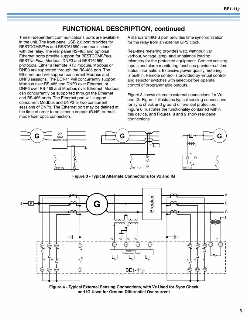
Figure 3 - Typical Alternate Connections for Vx and IG
Figure 4 - Typical External Sensing Connections, with Vx Used for Sync Check and IG Used for Ground Differential Overcurrent
Three independent communications ports are available in the unit. The front panel USB 2.0 port provides for BESTCOMSPlus and BEST61850 communications with the relay. The rear panel RS-485 and optional Ethernet ports provide support for BESTCOMSPlus, BESTNetPlus, Modbus, DNP3 and BEST61850 protocols. Either a Remote RTD module, Modbus or DNP3 are supported through the RS-485 port. The Ethernet port will support concurrent Modbus and DNP3 sessions. The BE1-11 will concurrently support Modbus over RS-485 and DNP3 over Ethernet, or DNP3 over RS-485 and Modbus over Ethernet. Modbus can concurrently be supported through the Ethernet and RS-485 ports. The Ethernet port will support concurrent Modbus and DNP3 or two concurrent sessions of DNP3. The Ethernet port may be defined at the time of order to be either a copper (RJ45) or multi-mode fiber optic connection.
A standard IRIG-B port provides time synchronization for the relay from an external GPS clock.
Real-time metering provides watt, watthour, var, varhour, voltage, amp, and unbalance loading telemetry for the protected equipment. Contact sensing inputs and alarm monitoring functions provide real-time status information. Extensive power quality metering is built-in. Remote control is provided by virtual control and selector switches with select-before-operate control of programmable outputs.
Figure 3 shows alternate external connections for Vx and IG. Figure 4 illustrates typical sensing connections for sync check and ground differential protection. Figure 6 illustrates the functionality contained within this device, and Figures 8 and 9 show rear panel connections.
BE1-11g
BESTLogicPlusBESTLogicPlus programmable logic provides the user with high flexibility in configuring a protection and control system.
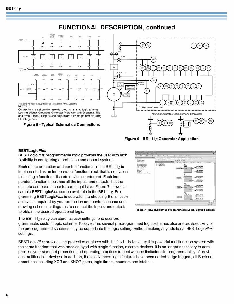
Each of the protection and control functions in the BE1-11g is implemented as an independent function block that is equivalent to its single function, discrete device counterpart. Each inde-pendent function block has all the inputs and outputs that the discrete component counterpart might have. Figure 7 shows a sample BESTLogicPlus screen available in the BE1-11g. Pro-gramming BESTLogicPlus is equivalent to choosing the function-al devices required by your protection and control scheme and drawing schematic diagrams to connect the inputs and outputs to obtain the desired operational logic.
The BE1-11g relay can store, as user settings, one user-pro-grammable, custom logic scheme. To save time, several preprogrammed logic schemes also are provided. Any of the preprogrammed schemes may be copied into the logic settings without making any additional BESTLogicPlus settings.
BESTLogicPlus provides the protection engineer with the flexibility to set up this powerful multifunction system with the same freedom that was once enjoyed with single-function, discrete devices. It is no longer necessary to com-promise your standard protection and operating practices to deal with the limitations in programmability of previ-ous multifunction devices. In addition, these advanced logic features have been added: edge triggers, all Boolean operations including XOR and XNOR gates, logic timers, counters and latches.
6
FUNCTIONAL DESCRIPTION, continued
Figure 6 - BE1-11g Generator Application
Figure 7 - BESTLogicPlus Programmable Logic, Sample Screen
Figure 5 - Typical External dc Connections
NOTES:Connections are shown for use with preprogrammed logic scheme Low Impedance Grounded Generator Protection with Sequential Trip and Sync Check. All inputs and outputs are fully programmable using BESTLogicPlus.
BE1-11g
7
FUNCTIONAL DESCRIPTION, continued
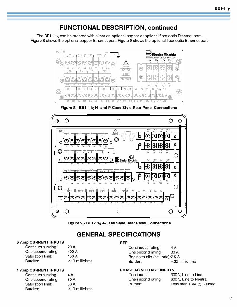
Figure 8 - BE1-11g H- and P-Case Style Rear Panel Connections
Figure 9 - BE1-11g J-Case Style Rear Panel Connections
5 Amp CURRENT INPUTS Continuous rating: 20 A One second rating: 400 A Saturation limit: 150 A Burden: <10 milliohms
1 Amp CURRENT INPUTS Continuous rating: 4 A One second rating: 80 A Saturation limit: 30 A Burden: <10 milliohms
GENERAL SPECIFICATIONSSEF Continuous rating: 4 A One second rating: 80 A Begins to clip (saturate):7.5 A Burden: <22 milliohms
PHASE AC VOLTAGE INPUTS Continuous: 300 V, Line to Line One second rating: 600 V, Line to Neutral Burden: Less than 1 VA @ 300Vac
The BE1-11g can be ordered with either an optional copper or optional fiber-optic Ethernet port. Figure 8 shows the optional copper Ethernet port. Figure 9 shows the optional fiber-optic Ethernet port.
BE1-11g
8
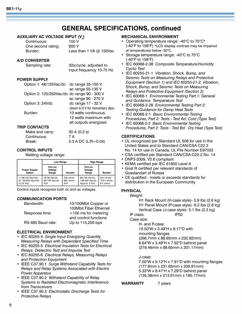
GENERAL SPECIFICATIONS, continuedAUXILIARY AC VOLTAGE INPUT (Vx) Continuous: 150 V One second rating: 600 V Burden: Less than 1 VA @ 150Vac
A/D CONVERTER Sampling rate: 32s/cycle, adjusted to input frequency 10-75 Hz
POWER SUPPLY Option 1: 48/125Vac/dc dc range 35-150 V ac range 55-135 V Option 2: 125/250Vac/dc dc range 90 - 300 V ac range 90 - 270 V Option 3: 24Vdc dc range 17 - 32 V (down to 8 V for momentary dips) Burden: 10 watts continuous, 12 watts maximum with all outputs energizedTRIP CONTACTS Make and carry: 30 A (0.2 s) Continuous: 7 A Break: 0.3 A DC (L/R=0.04) CONTROL INPUTS Wetting voltage range:
Power Supply Option
Low Range High Range
Turn-on Voltage Range Burden
Turn-on Voltage Range Burden
1) 48/125 Vac/Vdc 2) 125/250 Vac/Vdc 3) 24 Vdc
26-38 Vac/dc 69-100 Vac/dc N/A
23k ohms 66k ohms N/A
69-100 Vac/dc 138-200 Vac/dc Approx. 5 Vdc
53 k ohms 123 k ohms 6 k ohms
Control inputs recognize both dc and ac voltages.
COMMUNICATION PORTS Bandwidth: 10/100Mbit Copper or 100Mbit Fiber Ethernet Response time: <100 ms for metering and control functions RS-485 Baud rate: Up to 115,200 bps
ELECTRICAL ENVIRONMENT• IEC 60255-4 Single Input Energizing Quantity MeasuringRelayswithDependentSpecifiedTime• IEC 60255-5 ElectricalInsulationTestsforElectrical Relays.DielectricTestandImpulseTest• IEC 60255-6 Electrical Relays, Measuring Relays and Protection Equipment• IEEE C37.90.1 SurgeWithstandCapabilityTestsfor Relays and Relay Systems Associated with Electric Power Apparatus• IEEE C37.90.2 Withstand Capability of Relay Systems to Radiated Electromagnetic Interference fromTransceivers• IEEE C37.90.3 ElectrostaticDischargeTestsfor ProtectiveRelays
MECHANICAL ENVIRONMENT• Operating temperature range: -40°C to 70°C* (-40°F to 158°F) *LCD display contrast may be impaired at temperatures below -20°C.• Storage temperature range: -40°C to 70°C (-40°F to 158°F)• IEC 60068-2-38CompositeTemperature/Humidity CyclicTest• IEC 60255-21-1 Vibration, Shock, Bump, and SeismicTestsonMeasuringRelaysandProtective Equipment (Section 1) and IEC 60255-21-2, Vibration, Shock,Bump,andSeismicTestsonMeasuring RelaysandProtectiveEquipment(Section2)• IEC 60068-1 EnvironmentalTestingPart1:General andGuidance.TemperatureTest• IEC 60068-2-28 EnvironmentalTestingPart2: Testing-GuidanceforDampHeatTests• IEC 60068-2-1 BasicEnvironmentalTesting Procedures,Part2:Tests-TestAd:Cold(TypeTest)• IEC 60068-2-2 BasicEnvironmentalTesting Procedures,Part2:Tests-TestBd:DryHeat(TypeTest)
CERTIFICATIONS• UL recognized per Standard UL 508 for use in the United States and to Standard CAN/CSA C22.2 No. 14 for use in Canada, UL File Number E97033• CSA certified per Standard CAN/CSA-C22-2 No. 14• DNP3-2009, V2.6 compliant• KEMA certified per IEC 61850 Level A• Gost R certified per relevant standards of Gosstandart of Russia• CE qualified - meets or exceeds standards for distribution in the European Community
PHYSICAL Weight: H1 Rack Mount (H-case style)- 5.9 lbs (2.6 kg) H1 Panel Mount (P-case style)- 6.2 lbs (2.8 kg) Vertical Case (J-case style)- 5.1 lbs (2.3 kg) IP class: IP50 Case size: H- and P-case: 10.50"W x 3.49"H x 9.17"D with mounting flanges (266.7mm x 88.65mm x 232.92mm) 8.64"W x 3.49"H x 7.92"D behind panel (219.46mm x 88.65mm x 201.17mm) J-case: 7.00"W x 9.12"H x 7.91"D with mounting flanges (177.8mm x 231.65mm x 200.91mm) 5.33"W x 8.41"H x 7.29"D behind panel (135.38mm x 213.61mm x 185.17mm)
WARRANTY 7 years
BE1-11g
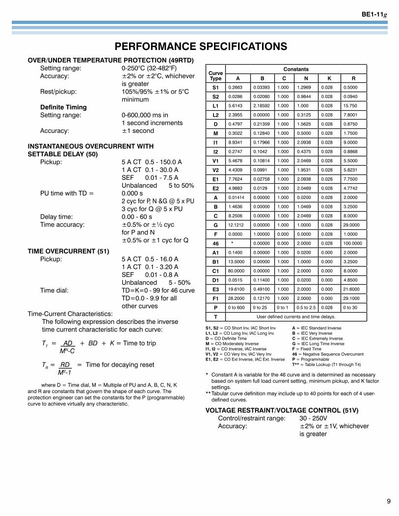
PERFORMANCE SPECIFICATIONSOVER/UNDER TEMPERATURE PROTECTION (49RTD) Setting range: 0-250°C (32-482°F) Accuracy: ±2% or ±2°C, whichever is greater Rest/pickup: 105%/95% ±1% or 5°C minimum Definite Timing Setting range: 0-600,000 ms in 1 second increments Accuracy: ±1 second
INSTANTANEOUS OVERCURRENT WITH SETTABLE DELAY (50) Pickup: 5 A CT 0.5 - 150.0 A 1 A CT 0.1 - 30.0 A SEF 0.01 - 7.5 A Unbalanced 5 to 50% PU time with TD = 0.000 s 2 cyc for P, N &G @ 5 x PU 3 cyc for Q @ 5 x PU Delay time: 0.00 - 60 s Time accuracy: ±0.5% or ±½ cyc for P and N ±0.5% or ±1 cyc for Q
TIME OVERCURRENT (51) Pickup: 5 A CT 0.5 - 16.0 A 1 A CT 0.1 - 3.20 A SEF 0.01 - 0.8 A Unbalanced 5 - 50% Time dial: TD=K=0 - 99 for 46 curve TD=0.0 - 9.9 for all other curves Time-Current Characteristics: The following expression describes the inverse time current characteristic for each curve:
TT = AD + BD + K = Time to trip MN-C
TR = RD = Time for decaying reset M2-1
where D = Time dial, M = Multiple of PU and A, B, C, N, K and R are constants that govern the shape of each curve. The protection engineer can set the constants for the P (programmable) curve to achieve virtually any characteristic.
CurveType
Constants
A B C N K R
S1 0.2663 0.03393 1.000 1.2969 0.028 0.5000
S2 0.0286 0.02080 1.000 0.9844 0.028 0.0940
L1 5.6143 2.18592 1.000 1.000 0.028 15.750
L2 2.3955 0.00000 1.000 0.3125 0.028 7.8001
D 0.4797 0.21359 1.000 1.5625 0.028 0.8750
M 0.3022 0.12840 1.000 0.5000 0.028 1.7500
I1 8.9341 0.17966 1.000 2.0938 0.028 9.0000
I2 0.2747 0.1042 1.000 0.4375 0.028 0.8868
V1 5.4678 0.10814 1.000 2.0469 0.028 5.5000
V2 4.4309 0.0991 1.000 1.9531 0.028 5.8231
E1 7.7624 0.02758 1.000 2.0938 0.028 7.7500
E2 4.9883 0.0129 1.000 2.0469 0.028 4.7742
A 0.01414 0.00000 1.000 0.0200 0.028 2.0000
B 1.4636 0.00000 1.000 1.0469 0.028 3.2500
C 8.2506 0.00000 1.000 2.0469 0.028 8.0000
G 12.1212 0.00000 1.000 1.0000 0.028 29.0000
F 0.0000 1.00000 0.000 0.0000 0.028 1.0000
46 * 0.00000 0.000 2.0000 0.028 100.0000
A1 0.1400 0.00000 1.000 0.0200 0.000 2.0000
B1 13.5000 0.00000 1.000 1.0000 0.000 3.2500
C1 80.0000 0.00000 1.000 2.0000 0.000 8.0000
D1 0.0515 0.11400 1.000 0.0200 0.000 4.8500
E3 19.6100 0.49100 1.000 2.0000 0.000 21.6000
F1 28.2000 0.12170 1.000 2.0000 0.000 29.1000
P 0 to 600 0 to 25 0 to 1 0.5 to 2.5 0.028 0 to 30
T User defined currents and time delays.
S1, S2 = CO Short Inv, IAC Short Inv A = IEC Standard Inverse L1, L2 = CO Long Inv, IAC Long Inv B = IEC Very InverseD = CO Definite Time C = IEC Extremely InverseM = CO Moderately Inverse G = IEC Long Time InverseI1, I2 = CO Inverse, IAC Inverse F = Fixed Time V1, V2 = CO Very Inv, IAC Very Inv 46 = Negative Sequence OvercurrentE1, E2 = CO Ext Inverse, IAC Ext. Inverse P = Programmable T** = Table Lookup (T1 through T4)
* Constant A is variable for the 46 curve and is determined as necessary based on system full load current setting, minimum pickup, and K factor settings.** Tabular curve definition may include up to 40 points for each of 4 user- defined curves.
VOLTAGE RESTRAINT/VOLTAGE CONTROL (51V) Control/restraint range: 30 - 250V Accuracy: ±2% or ±1V, whichever is greater
9
BE1-11g
10
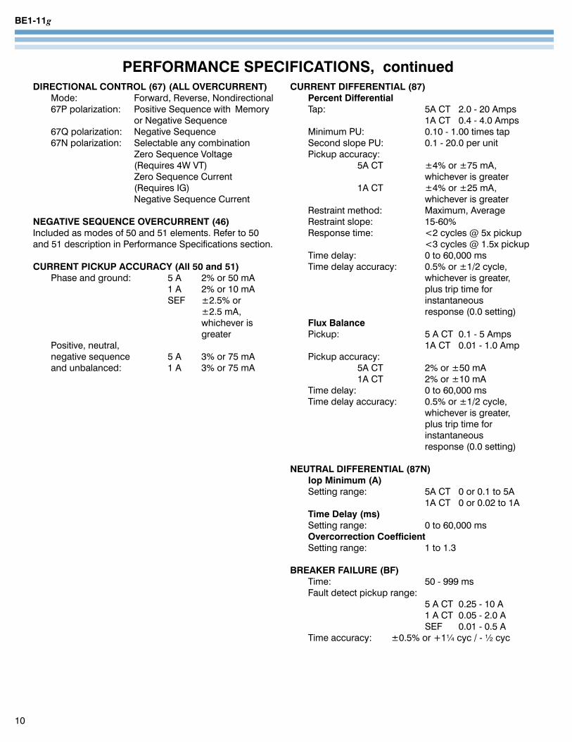
PERFORMANCE SPECIFICATIONS, continuedDIRECTIONAL CONTROL (67) (ALL OVERCURRENT) Mode: Forward, Reverse, Nondirectional 67P polarization: Positive Sequence with Memory or Negative Sequence 67Q polarization: Negative Sequence 67N polarization: Selectable any combination Zero Sequence Voltage (Requires 4W VT) Zero Sequence Current (Requires IG) Negative Sequence Current
NEGATIVE SEQUENCE OVERCURRENT (46)Included as modes of 50 and 51 elements. Refer to 50 and 51 description in Performance Specifications section.
CURRENT PICKUP ACCURACY (All 50 and 51) Phase and ground: 5 A 2% or 50 mA 1 A 2% or 10 mA SEF ±2.5% or ±2.5 mA, whichever is greater Positive, neutral, negative sequence 5 A 3% or 75 mA and unbalanced: 1 A 3% or 75 mA
CURRENT DIFFERENTIAL (87) Percent Differential Tap: 5A CT 2.0 - 20 Amps 1A CT 0.4 - 4.0 Amps Minimum PU: 0.10 - 1.00 times tap Second slope PU: 0.1 - 20.0 per unit Pickup accuracy: 5A CT ±4% or ±75 mA, whichever is greater 1A CT ±4% or ±25 mA, whichever is greater Restraint method: Maximum, Average Restraint slope: 15-60% Response time: <2 cycles @ 5x pickup <3 cycles @ 1.5x pickup Time delay: 0 to 60,000 ms Time delay accuracy: 0.5% or ±1/2 cycle, whichever is greater, plus trip time for instantaneous response (0.0 setting) Flux Balance Pickup: 5 A CT 0.1 - 5 Amps 1A CT 0.01 - 1.0 Amp Pickup accuracy: 5A CT 2% or ±50 mA 1A CT 2% or ±10 mA Time delay: 0 to 60,000 ms Time delay accuracy: 0.5% or ±1/2 cycle, whichever is greater, plus trip time for instantaneous response (0.0 setting)
NEUTRAL DIFFERENTIAL (87N) Iop Minimum (A) Setting range: 5A CT 0 or 0.1 to 5A 1A CT 0 or 0.02 to 1A Time Delay (ms) Setting range: 0 to 60,000 ms Overcorrection Coefficient Setting range: 1 to 1.3
BREAKER FAILURE (BF) Time: 50 - 999 ms Fault detect pickup range: 5 A CT 0.25 - 10 A 1 A CT 0.05 - 2.0 A SEF 0.01 - 0.5 A Time accuracy: ±0.5% or +1¼ cyc / - ½ cyc
BE1-11g
PERFORMANCE SPECIFICATIONS, continued
11
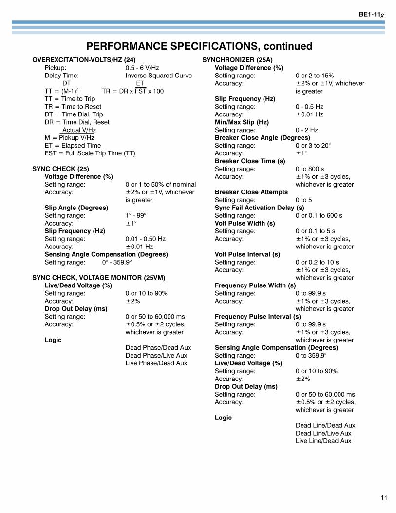
OVEREXCITATION-VOLTS/HZ (24) Pickup: 0.5 - 6 V/Hz Delay Time: Inverse Squared Curve DT ET TT = (M-1)2 TR = DR x FST x 100 TT = Time to Trip TR = Time to Reset DT = Time Dial, Trip DR = Time Dial, Reset Actual V/Hz M = Pickup V/Hz ET = Elapsed Time FST = Full Scale Trip Time (TT)
SYNC CHECK (25) Voltage Difference (%) Setting range: 0 or 1 to 50% of nominal Accuracy: ±2% or ±1V, whichever is greater Slip Angle (Degrees) Setting range: 1° - 99° Accuracy: ±1° Slip Frequency (Hz) Setting range: 0.01 - 0.50 Hz Accuracy: ±0.01 Hz Sensing Angle Compensation (Degrees) Setting range: 0° - 359.9°
SYNC CHECK, VOLTAGE MONITOR (25VM) Live/Dead Voltage (%) Setting range: 0 or 10 to 90% Accuracy: ±2% Drop Out Delay (ms) Setting range: 0 or 50 to 60,000 ms Accuracy: ±0.5% or ±2 cycles, whichever is greater Logic Dead Phase/Dead Aux Dead Phase/Live Aux Live Phase/Dead Aux
SYNCHRONIZER (25A) Voltage Difference (%) Setting range: 0 or 2 to 15% Accuracy: ±2% or ±1V, whichever is greater Slip Frequency (Hz) Setting range: 0 - 0.5 Hz Accuracy: ±0.01 Hz Min/Max Slip (Hz) Setting range: 0 - 2 Hz Breaker Close Angle (Degrees) Setting range: 0 or 3 to 20° Accuracy: ±1° Breaker Close Time (s) Setting range: 0 to 800 s Accuracy: ±1% or ±3 cycles, whichever is greater Breaker Close Attempts Setting range: 0 to 5 Sync Fail Activation Delay (s) Setting range: 0 or 0.1 to 600 s Volt Pulse Width (s) Setting range: 0 or 0.1 to 5 s Accuracy: ±1% or ±3 cycles, whichever is greater Volt Pulse Interval (s) Setting range: 0 or 0.2 to 10 s Accuracy: ±1% or ±3 cycles, whichever is greater Frequency Pulse Width (s) Setting range: 0 to 99.9 s Accuracy: ±1% or ±3 cycles, whichever is greater Frequency Pulse Interval (s) Setting range: 0 to 99.9 s Accuracy: ±1% or ±3 cycles, whichever is greater Sensing Angle Compensation (Degrees) Setting range: 0 to 359.9° Live/Dead Voltage (%) Setting range: 0 or 10 to 90% Accuracy: ±2% Drop Out Delay (ms) Setting range: 0 or 50 to 60,000 ms Accuracy: ±0.5% or ±2 cycles, whichever is greater Logic Dead Line/Dead Aux Dead Line/Live Aux Live Line/Dead Aux
BE1-11g
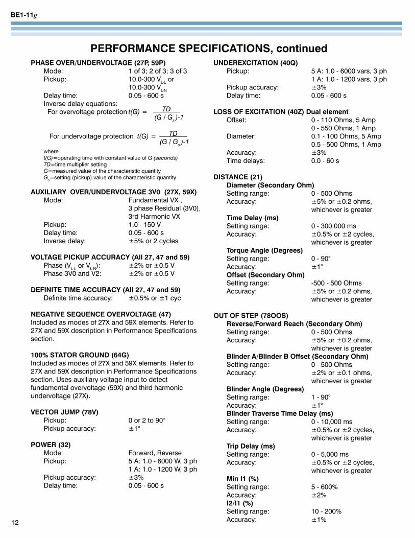
PERFORMANCE SPECIFICATIONS, continuedPHASE OVER/UNDERVOLTAGE (27P, 59P) Mode: 1 of 3; 2 of 3; 3 of 3 Pickup: 10.0-300 VL-L or 10.0-300 VL-N Delay time: 0.05 - 600 s Inverse delay equations: For overvoltage protection t(G)= TD (G/Gs )-1
For undervoltage protection t(G)= TD (G/Gs )-1 where t(G)=operating time with constant value of G(seconds) TD=time multiplier setting G=measured value of the characteristic quantity GS=setting (pickup) value of the characteristic quantity
AUXILIARY OVER/UNDERVOLTAGE 3V0 (27X, 59X) Mode: Fundamental VX , 3 phase Residual (3V0), 3rd Harmonic VX Pickup: 1.0 - 150 V Delay time: 0.05 - 600 s Inverse delay: ±5% or 2 cycles
VOLTAGE PICKUP ACCURACY (All 27, 47 and 59) Phase (VL-L or VL-N): ±2% or ±0.5 V Phase 3V0 and V2: ±2% or ±0.5 V
DEFINITE TIME ACCURACY (All 27, 47 and 59) Definite time accuracy: ±0.5% or ±1 cyc
NEGATIVE SEQUENCE OVERVOLTAGE (47)Included as modes of 27X and 59X elements. Refer to 27X and 59X description in Performance Specifications section.
100% STATOR GROUND (64G)Included as modes of 27X and 59X elements. Refer to 27X and 59X description in Performance Specifications section. Uses auxiliary voltage input to detect fundamental overvoltage (59X) and third harmonic undervoltage (27X).
VECTOR JUMP (78V) Pickup: 0 or 2 to 90° Pickup accuracy: ±1°
POWER (32) Mode: Forward, Reverse Pickup: 5 A: 1.0 - 6000 W, 3 ph 1 A: 1.0 - 1200 W, 3 ph Pickup accuracy: ±3% Delay time: 0.05 - 600 s
UNDEREXCITATION (40Q) Pickup: 5 A: 1.0 - 6000 vars, 3 ph 1 A: 1.0 - 1200 vars, 3 ph Pickup accuracy: ±3% Delay time: 0.05 - 600 s
LOSS OF EXCITATION (40Z) Dual element Offset: 0 - 110 Ohms, 5 Amp 0 - 550 Ohms, 1 Amp Diameter: 0.1 - 100 Ohms, 5 Amp 0.5 - 500 Ohms, 1 Amp Accuracy: ±3% Time delays: 0.0 - 60 s
DISTANCE (21) Diameter (Secondary Ohm) Setting range: 0 - 500 Ohms Accuracy: ±5% or ±0.2 ohms, whichever is greater Time Delay (ms) Setting range: 0 - 300,000 ms Accuracy: ±0.5% or ±2 cycles, whichever is greater Torque Angle (Degrees) Setting range: 0 - 90° Accuracy: ±1° Offset (Secondary Ohm) Setting range: -500 - 500 Ohms Accuracy: ±5% or ±0.2 ohms, whichever is greater
OUT OF STEP (78OOS) Reverse/Forward Reach (Secondary Ohm) Setting range: 0 - 500 Ohms Accuracy: ±5% or ±0.2 ohms, whichever is greater Blinder A/Blinder B Offset (Secondary Ohm) Setting range: 0 - 500 Ohms Accuracy: ±2% or ±0.1 ohms, whichever is greater Blinder Angle (Degrees) Setting range: 1 - 90° Accuracy: ±1° Blinder Traverse Time Delay (ms) Setting range: 0 - 10,000 ms Accuracy: ±0.5% or ±2 cycles, whichever is greater Trip Delay (ms) Setting range: 0 - 5,000 ms Accuracy: ±0.5% or ±2 cycles, whichever is greater Min I1 (%) Setting range: 5 - 600% Accuracy: ±2% I2/I1 (%) Setting range: 10 - 200% Accuracy: ±1%12
BE1-11g
PERFORMANCE SPECIFICATIONS, continued
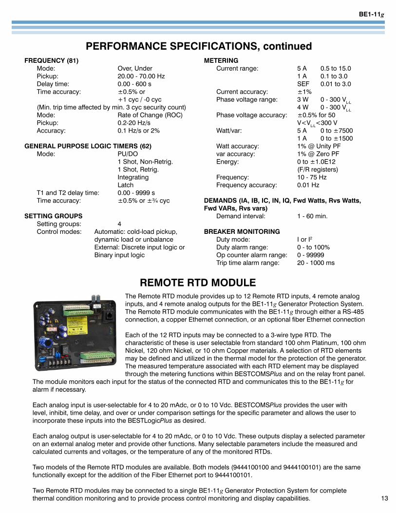
The Remote RTD module provides up to 12 Remote RTD inputs, 4 remote analog inputs, and 4 remote analog outputs for the BE1-11g Generator Protection System. The Remote RTD module communicates with the BE1-11g through either a RS-485 connection, a copper Ethernet connection, or an optional fiber Ethernet connection
Each of the 12 RTD inputs may be connected to a 3-wire type RTD. The characteristic of these is user selectable from standard 100 ohm Platinum, 100 ohm Nickel, 120 ohm Nickel, or 10 ohm Copper materials. A selection of RTD elements may be defined and utilized in the thermal model for the protection of the generator. The measured temperature associated with each RTD element may be displayed through the metering functions within BESTCOMSPlus and on the relay front panel.
The module monitors each input for the status of the connected RTD and communicates this to the BE1-11g for alarm if necessary.
Each analog input is user-selectable for 4 to 20 mAdc, or 0 to 10 Vdc. BESTCOMSPlus provides the user with level, inhibit, time delay, and over or under comparison settings for the specific parameter and allows the user to incorporate these inputs into the BESTLogicPlus as desired.
Each analog output is user-selectable for 4 to 20 mAdc, or 0 to 10 Vdc. These outputs display a selected parameter on an external analog meter and provide other functions. Many selectable parameters include the measured and calculated currents and voltages, or the temperature of any of the monitored RTDs.
Two models of the Remote RTD modules are available. Both models (9444100100 and 9444100101) are the same functionally except for the addition of the Fiber Ethernet port to 9444100101. Two Remote RTD modules may be connected to a single BE1-11g Generator Protection System for complete thermal condition monitoring and to provide process control monitoring and display capabilities. 13
FREQUENCY (81) Mode: Over, Under Pickup: 20.00 - 70.00 Hz Delay time: 0.00 - 600 s Time accuracy: ±0.5% or +1 cyc / -0 cyc (Min. trip time affected by min. 3 cyc security count) Mode: Rate of Change (ROC) Pickup: 0.2-20 Hz/s Accuracy: 0.1 Hz/s or 2%
GENERAL PURPOSE LOGIC TIMERS (62) Mode: PU/DO 1 Shot, Non-Retrig. 1 Shot, Retrig. Integrating Latch T1 and T2 delay time: 0.00 - 9999 s Time accuracy: ±0.5% or ±¾ cyc
SETTING GROUPS Setting groups: 4 Control modes: Automatic: cold-load pickup, dynamic load or unbalance External: Discrete input logic or Binary input logic
METERING Current range: 5 A 0.5 to 15.0 1 A 0.1 to 3.0 SEF 0.01 to 3.0 Current accuracy: ±1% Phase voltage range: 3 W 0 - 300 VL-L 4 W 0 - 300 VL-L Phase voltage accuracy: ±0.5% for 50 V<VL-L<300 V Watt/var: 5 A 0 to ±7500 1 A 0 to ±1500 Watt accuracy: 1% @ Unity PF var accuracy: 1% @ Zero PF Energy: 0 to ±1.0E12 (F/R registers) Frequency: 10 - 75 Hz Frequency accuracy: 0.01 Hz DEMANDS (IA, IB, IC, IN, IQ, Fwd Watts, Rvs Watts, Fwd VARs, Rvs vars) Demand interval: 1 - 60 min.
BREAKER MONITORING Duty mode: I or I2 Duty alarm range: 0 - to 100% Op counter alarm range: 0 - 99999 Trip time alarm range: 20 - 1000 ms
REMOTE RTD MODULE
BE1-11g
14
POWER SUPPLY 125/250 Vac/dc dc range 90-300 V ac range 90-270 V Burden: 8 Watts continuous 9 Watts maximum
ALARM CONTACT Form C Make and carry: 30A (0.2 s) Continuous: 7A Break: 0.3A dc (L/R-0.04)
ELECTRICAL ENVIRONMENT• IEC 60255-4: Single Input Energizing Quantity Measuring Relays with Dependent Specified Time• IEC 60255-5: Electrical Insulation Tests for Electrical
Relays, Dielectric Test and Impulse Test
• IEC 60255-6: Electrical Relays - Measuring Relays and Protection Equipment
• IEEE C37.90: Standard for Relays and Relay Systems with Electric Power Apparatus, S. 8.
• IEEE C37.90.1: Surge Withstand Capability (SWC) Tests for Relays and Relay Systems Associated with Electric Power Apparatus
• IEEE C37.90.2: Withstand Capability of Relay Systems to Radiated Electromagnetic Interference from Transceivers
CERTIFICATIONS• UL recognized per Standard 508, UL File Number
E97035• CSA certified to Standard CAN/CSA-C22.2 Number 14-M91• CE qualified
GENERAL SPECIFICATIONS, REMOTE RTD MODULE
FUNCTIONAL DESCRIPTION, RTD MODULE12 RTD Inputs• Selectable RTD types 3 wire RTDs with the following characteristics: - 100 ohm Platinum (DIN43760) - 100 ohm and 120 ohm Nickel - 10 ohm Copper• Range: -50 to 250°C (-58 to 482°F)• Accuracy: ±2°C (3.6°F)• Maximum Lead Length: 150 ft. (45.72m) with
22awg wire• Sensing current level is 2.5 mA• Isolation: 35VP-P
4 Analog Inputs• BESTCOMSPlus setting selects either a 4 to 20 mAdc
or a 0 to 10 Vdc input range• Accuracy: ±1% of full scale
4 Analog Outputs• BESTCOMSPlus setting selects either a 4 to 20 mAdc
or a 0 to 10 Vdc output range• Accuracy: ±1% of full scale• Output capability: - 4 to 20 mAdc into a maximum 500 ohm load - 0 to 10 Vdc across a minimum 800 ohm load
Programmable fail safe alarm• Form C• Alarms for programmable selection of: - Analog Failure - Calibration Error - Defaults loaded due to file system operational error - Flash Memory Failure - Non Volatile Memory Handler errors
Communications• RS-485 (19,200 baud)• Copper Ethernet Connection - 10BASE-T/100BASE-TX
RJ45 type connection port for CAT 5 copper wire• Optional Fiber Optic Ethernet Connection - 100BASE-FX
ST type connection port for multimode fiber (9444100101)• Password Security
Real-Time Status of RTD Module is indicated by:• A green LED on the Module - Slow flashing - Communications established - Steady on - Power applied - Quick flashing - Communications lost• Communications will report to the BE1-11g - RTD status (Open, shorted, or missing) - Analog Input Status
Reporting Functions• Version information• Each RTD type• Communications settings• Module ID
BE1-11g
15
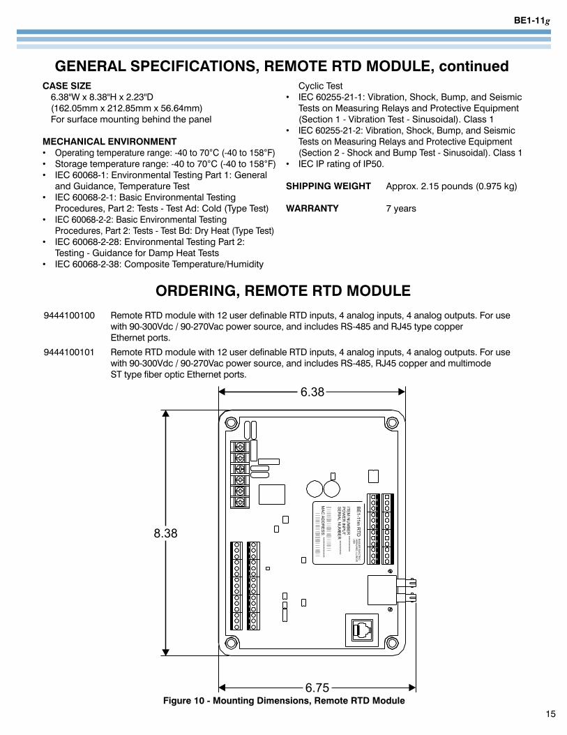
CASE SIZE 6.38"W x 8.38"H x 2.23"D (162.05mm x 212.85mm x 56.64mm) For surface mounting behind the panel
MECHANICAL ENVIRONMENT• Operating temperature range: -40 to 70°C (-40 to 158°F)• Storage temperature range: -40 to 70°C (-40 to 158°F)• IEC 60068-1: Environmental Testing Part 1: General
and Guidance, Temperature Test• IEC 60068-2-1: Basic Environmental Testing
Procedures, Part 2: Tests - Test Ad: Cold (Type Test)• IEC 60068-2-2: Basic Environmental Testing
Procedures, Part 2: Tests - Test Bd: Dry Heat (Type Test)• IEC 60068-2-28: Environmental Testing Part 2:
Testing - Guidance for Damp Heat Tests• IEC 60068-2-38: Composite Temperature/Humidity
Cyclic Test• IEC 60255-21-1: Vibration, Shock, Bump, and Seismic
Tests on Measuring Relays and Protective Equipment (Section 1 - Vibration Test - Sinusoidal). Class 1
• IEC 60255-21-2: Vibration, Shock, Bump, and Seismic Tests on Measuring Relays and Protective Equipment (Section 2 - Shock and Bump Test - Sinusoidal). Class 1
• IEC IP rating of IP50.
SHIPPING WEIGHT Approx. 2.15 pounds (0.975 kg)
WARRANTY 7 years
GENERAL SPECIFICATIONS, REMOTE RTD MODULE, continued
Figure 10 - Mounting Dimensions, Remote RTD Module
ORDERING, REMOTE RTD MODULE 9444100100 Remote RTD module with 12 user definable RTD inputs, 4 analog inputs, 4 analog outputs. For use with 90-300Vdc / 90-270Vac power source, and includes RS-485 and RJ45 type copper Ethernet ports.9444100101 Remote RTD module with 12 user definable RTD inputs, 4 analog inputs, 4 analog outputs. For use with 90-300Vdc / 90-270Vac power source, and includes RS-485, RJ45 copper and multimode ST type fiber optic Ethernet ports.
BE1-11g
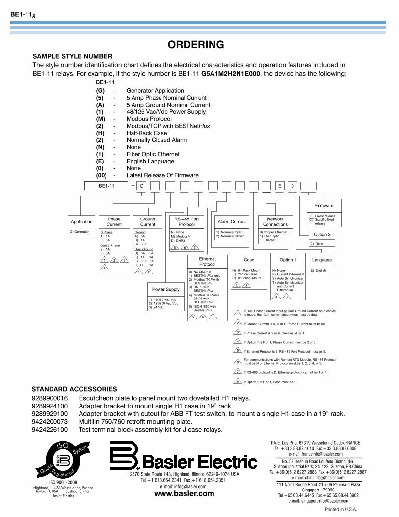
ORDERING SAMPLE STYLE NUMBERThe style number identification chart defines the electrical characteristics and operation features included in BE1-11 relays. For example, if the style number is BE1-11 G5A1M2H2N1E000, the device has the following: BE1-11 (G) - Generator Application (5) - 5 Amp Phase Nominal Current (A) - 5 Amp Ground Nominal Current (1) - 48/125 Vac/Vdc Power Supply (M) - Modbus Protocol (2) - Modbus/TCP with BESTNetPlus (H) - Half-Rack Case (2) - Normally Closed Alarm (N) - None (1) - Fiber Optic Ethernet (E) - English Language (0) - None (00) - Latest Release Of Firmware
STANDARD ACCESSORIES9289900016 Escutcheon plate to panel mount two dovetailed H1 relays.9289924100 Adapter bracket to mount single H1 case in 19” rack.9289929100 Adapter bracket with cutout for ABB FT test switch, to mount a single H1 case in a 19” rack.9424200073 Multilin 750/760 retrofit mounting plate.9424226100 Test terminal block assembly kit for J-case relays.
Printed in U.S.A.
www.basler.com
12570 State Route 143, Highland, Illinois 62249-1074 USA Tel +1 618.654.2341 Fax +1 618.654.2351
e-mail: [email protected]
No. 59 Heshun Road Loufeng District (N), Suzhou Industrial Park, 215122, Suzhou, P.R.China
Tel +86(0)512 8227 2888 Fax +86(0)512 8227 2887e-mail: [email protected]
P.A.E. Les Pins, 67319 Wasselonne Cedex FRANCETel +33 3.88.87.1010 Fax +33 3.88.87.0808
e-mail: [email protected]
111 North Bridge Road #15-06 Peninsula PlazaSingapore 179098
Tel +65 68.44.6445 Fax +65 65.68.44.8902 e-mail: [email protected]