Embed Size (px)
Citation preview

INSTRUCTION MANUAL FOR
DIRECTIONAL POWER RELAYS BE1-32 and BE1-32O/U
Publication: 9171100990 Revision: R 09/07 www .
Elec
tricalP
artM
anua
ls . c
om

www . El
ectric
alPar
tMan
uals
. com

9171100990 Rev R BE1-32R, BE1-32O/U Introduction i
INTRODUCTION This instruction manual provides information about the operation and installation of the BE1-32R and BE1-32O/U Directional Power Relays. To accomplish this, the following information is provided:
• General Information and Specifications • Controls and Indicators • Functional Description • Installation • Tests and Adjustments
WARNING! To avoid personal injury or equipment damage, only qualified personnel should perform the procedures in this manual.
NOTE Be sure that the relay is hard-wired to earth ground with no smaller than 12 AWG copper wire attached to the ground terminal on the rear of the unit case. When the relay is configured in a system with other devices, it is recommended to use a separate lead to the ground bus from each unit.
www . El
ectric
alPar
tMan
uals
. com
ii BE1-32R, BE1-32O/U Introduction 9171100990 Rev R
First Printing: September 1986
Printed in USA
© 1986, 1994-1995, 1998, 2000-2003, 2005-2007 Basler Electric, Highland Illinois 62249 USA
All Rights Reserved
September 2007
It is not the intention of this manual to cover all details and variations in equipment, nor does this manual provide data for every possible contingency regarding installation or operation. The availability and design of all features and options are subject to modification without notice. Should further information be required, contact Basler Electric.
BASLER ELECTRIC ROUTE 143, BOX 269
HIGHLAND IL 62249 USA http://www.basler.com, [email protected]
PHONE +1 618.654.2341 FAX +1 618.654.2351
CONFIDENTIAL INFORMATION of Basler Electric, Highland Illinois, USA. It is loaned for confidential use, subject to return on request, and with the mutual understanding that it will not be used in any manner detrimental to the interest of Basler Electric.
www . El
ectric
alPar
tMan
uals
. com
9171100990 Rev R BE1-32R, BE1-32O/U Introduction iii
REVISION HISTORY
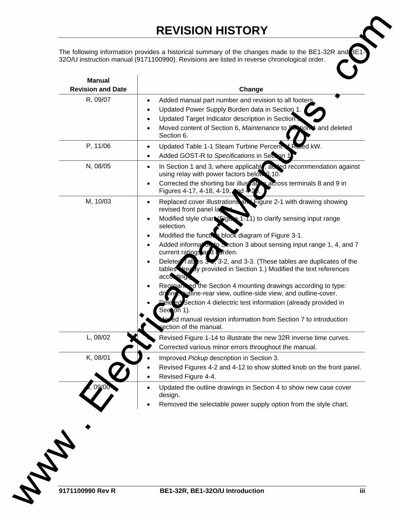
The following information provides a historical summary of the changes made to the BE1-32R and BE1-32O/U instruction manual (9171100990). Revisions are listed in reverse chronological order.
Manual Revision and Date Change
R, 09/07 • Added manual part number and revision to all footers. • Updated Power Supply Burden data in Section 1. • Updated Target Indicator description in Section 3. • Moved content of Section 6, Maintenance to Section 4 and deleted
Section 6. P, 11/06 • Updated Table 1-1 Steam Turbine Percent of Rated kW.
• Added GOST-R to Specifications in Section 1. N, 08/05 • In Section 1 and 3, where applicable, added recommendation against
using relay with power factors below 0.10. • Corrected the shorting bar illustration across terminals 8 and 9 in
Figures 4-17, 4-18, 4-19, and 4-20. M, 10/03 • Replaced cover illustrations and Figure 2-1 with drawing showing
revised front panel layout. • Modified style chart (Figure 1-11) to clarify sensing input range
selection. • Modified the function block diagram of Figure 3-1. • Added information to Section 3 about sensing input range 1, 4, and 7
current ratings and burden. • Deleted Tables 3-1, 3-2, and 3-3. (These tables are duplicates of the
tables already provided in Section 1.) Modified the text references accordingly.
• Reorganized the Section 4 mounting drawings according to type: drilling, outline-rear view, outline-side view, and outline-cover.
• Deleted Section 4 dielectric test information (already provided in Section 1).
• Moved manual revision information from Section 7 to introduction section of the manual.
L, 08/02 • Revised Figure 1-14 to illustrate the new 32R inverse time curves. • Corrected various minor errors throughout the manual.
K, 08/01 • Improved Pickup description in Section 3. • Revised Figures 4-2 and 4-12 to show slotted knob on the front panel. • Revised Figure 4-4.
J, 09/00 • Updated the outline drawings in Section 4 to show new case cover design.
• Removed the selectable power supply option from the style chart.
www . El
ectric
alPar
tMan
uals
. com

iv BE1-32R, BE1-32O/U Introduction 9171100990 Rev R
Manual Revision and Date Change
H, 06/98 • Deleted references to Service Manual 9171100620. • Changed power supply voltage and burden data listed in Section 1. • Added information to instantaneous response time specification in
Section 1. • Added Figure 1-13 and associated paragraphs describing the
underpower element. • Corrected the power supply entries in the style chart. • Add information to the pickup accuracy specification in Section 1. • Added information to the Power Supply paragraph in Section 3. • Added outline drawings to cover all available case options. • Changed the case ground symbol shown in the Internal Connection
diagrams. • Revised the manual format.
G, 07/95 • Revised the pickup accuracy stated in Specifications of Section 1. • Corrected isolation specification in Section 1 and dielectric test values
in Section 4. • Added Note 3 to Figure 4-20. • Corrected CT sensing connections in Figure 4-21. • Moved polarity indications in Figure 4-25. • Deleted ±30° label in Figure 5-5 and corrected equation.
F, 06/94 • Added 120 Vac label to Figure 1-11. • Changed reference for Figure 1-12 from Specifications, Timing
Accuracies to Timing Adjustment Range. • Added Figure 1-13. • Corrected input sensing terminal numbers in Figure 4-23. • Deleted reference to Figure 3-8 (Figure 3-8 was replaced by Figure 1-
13.) E, 02/94 • Added internal connection and typical connection diagrams to Section
4. • Added Phase Rotation Sensitivity to Section 1. • Revised the format of the manual.
www . El
ectric
alPar
tMan
uals
. com

9171100990 Rev R BE1-32R, BE1-32O/U Introduction v
CONTENTS SECTION 1 • GENERAL INFORMATION ................................................................................................ 1-1 SECTION 2 • CONTROLS AND INDICATORS........................................................................................ 2-1 SECTION 3 • FUNCTIONAL DESCRIPTION ........................................................................................... 3-1 SECTION 4 • INSTALLATION .................................................................................................................. 4-1 SECTION 5 • TESTING ............................................................................................................................ 5-1
www . El
ectric
alPar
tMan
uals
. com

vi BE1-32R, BE1-32O/U Introduction 9171100990 Rev R
This page intentionally left blank.
www . El
ectric
alPar
tMan
uals
. com
9171100990 Rev R BE1-32R, BE1-32O/U General Information i
SECTION 1 • GENERAL INFORMATION TABLE OF CONTENTS
SECTION 1 • GENERAL INFORMATION ................................................................................................ 1-1
INTRODUCTION.................................................................................................................................... 1-1 APPLICATION ....................................................................................................................................... 1-1
Example 1: Anti-Motoring ................................................................................................................... 1-1 Example 2: Co-Generator Control...................................................................................................... 1-2 Example 3: Generator Overload ........................................................................................................ 1-3 Example 4: Intertie ............................................................................................................................. 1-3 Example 5: Delayed Electrical Trip .................................................................................................... 1-4 Example 6: Breaker Opening Detection............................................................................................. 1-4 Example 7: Reactive Power (Vars) Detection .................................................................................... 1-6
MODEL AND STYLE NUMBER............................................................................................................. 1-7 Style Number Example....................................................................................................................... 1-8
SPECIFICATIONS ................................................................................................................................. 1-9 Current Sensing ................................................................................................................................. 1-9 Voltage Sensing ................................................................................................................................. 1-9 Targets ............................................................................................................................................... 1-9 Output Circuits.................................................................................................................................. 1-10 Power Supply ................................................................................................................................... 1-10 Pickup............................................................................................................................................... 1-10 Timing............................................................................................................................................... 1-10 Timing—continued ........................................................................................................................... 1-13 Power Range (Pickup) ..................................................................................................................... 1-13 Type Tests........................................................................................................................................ 1-13 UL Recognition................................................................................................................................. 1-14 GOST-R............................................................................................................................................ 1-14 Temperature..................................................................................................................................... 1-14 Weight .............................................................................................................................................. 1-14
Figures Figure 1-1. Single-Phase........................................................................................................................... 1-1 Figure 1-2. Power Relay Start Control....................................................................................................... 1-2 Figure 1-3. Power Relay Start/Stop Control .............................................................................................. 1-3 Figure 1-4. Power Relay Distribution Protection ....................................................................................... 1-3 Figure 1-5. Single-Phase, Non-Electrical Trip Supervision ....................................................................... 1-4 Figure 1-6. Breaker Opening Detection..................................................................................................... 1-4 Figure 1-7. Power Factor, First and Second Quadrants............................................................................ 1-5 Figure 1-8. Power Factor, Third and Fourth Quadrants ............................................................................ 1-5 Figure 1-9. Underpower Tripping............................................................................................................... 1-5 Figure 1-11. Modified Type A Sensing ...................................................................................................... 1-7 Figure 1-12. Style Number Identification Chart ......................................................................................... 1-8 Figure 1-13. Overpower Instantaneous Response Time ........................................................................ 1-11 Figure 1-14. Underpower Instantaneous Response Time ...................................................................... 1-11 Figure 1-15. Overpower Inverse Time Characteristic Curves ................................................................. 1-12
Tables Table 1-1. Motoring Reverse Power Requirements .................................................................................. 1-2 Table 1-2. Current Sensing Burden in Ohms ............................................................................................ 1-9 Table 1-3. Power Supply Specifications.................................................................................................. 1-10 Table 1-4. Power Pickup Ranges............................................................................................................ 1-13
www . El
ectric
alPar
tMan
uals
. com

ii BE1-32R, BE1-32O/U General Information 9171100990 Rev R
This page intentionally left blank.
www . El
ectric
alPar
tMan
uals
. com
9171100990 Rev R BE1-32R, BE1-32O/U General Information 1-1
SECTION 1 • GENERAL INFORMATION INTRODUCTION BE1-32R, Directional Overpower and BE1-32O/U, Directional Over/Underpower Relays sense real power (IE times the cosine of θ). These solid-state relays are designed for use in single- or three-phase systems to protect equipment against overpower and/or underpower conditions. They may also be used in the supervisory control of circuits.
APPLICATION Directional Power Relays are typically used in applications where excessive power flow in the tripping direction is bad. Over and/or underpower protection is desirable where: • Power flows into a generator, indicating loss of prime mover torque (motoring). • Power flows into the secondary of a station distribution transformer, indicating an industrial or private
customer is supplying power into the utility system. • Excessive load has been connected to a system. • Overload has been placed on a distribution system. • Overspeeding is a prime concern. • An open breaker creates an overload on a local generation facility. • Loss of excitation can be determined by var sensing.
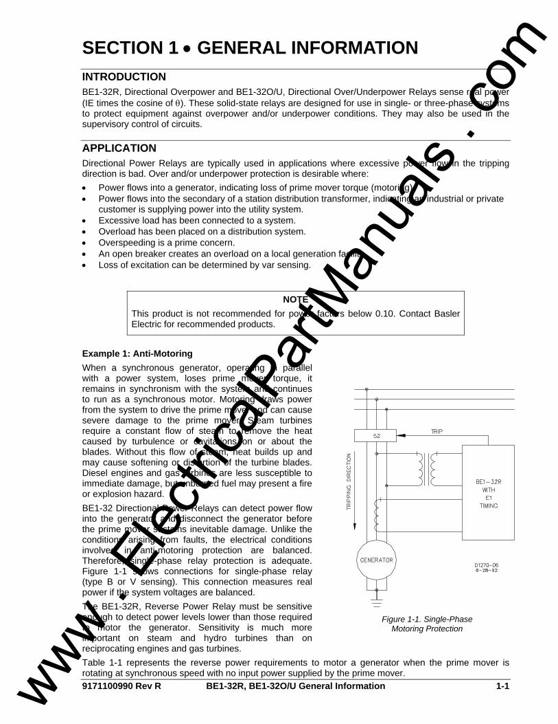
Example 1: Anti-Motoring When a synchronous generator, operating in parallel with a power system, loses prime mover torque, it remains in synchronism with the system and continues to run as a synchronous motor. Motoring draws power from the system to drive the prime mover and can cause severe damage to the prime mover. Steam turbines require a constant flow of steam to remove the heat caused by turbulence or cavitations on or about the blades. Without this flow of steam, heat builds up and may cause softening or distortion of the turbine blades. Diesel engines and gas turbines are less susceptible to immediate damage, but unburned fuel may present a fire or explosion hazard. BE1-32 Directional Power Relays can detect power flow into the generator and disconnect the generator before the prime mover sustains inevitable damage. Unlike the conditions arising from faults, the electrical conditions involved in anti-motoring protection are balanced. Therefore, single-phase relay protection is adequate. Figure 1-1 shows connections for single-phase relay (type B or V sensing). This connection measures real power if the system voltages are balanced. The BE1-32R, Reverse Power Relay must be sensitive enough to detect power levels lower than those required to motor the generator. Sensitivity is much more important on steam and hydro turbines than on reciprocating engines and gas turbines.
Figure 1-1. Single-Phase
Motoring Protection
Table 1-1 represents the reverse power requirements to motor a generator when the prime mover is rotating at synchronous speed with no input power supplied by the prime mover.
NOTE This product is not recommended for power factors below 0.10. Contact Basler Electric for recommended products.
www . El
ectric
alPar
tMan
uals
. com
1-2 BE1-32R, BE1-32O/U General Information 9171100990 Rev R
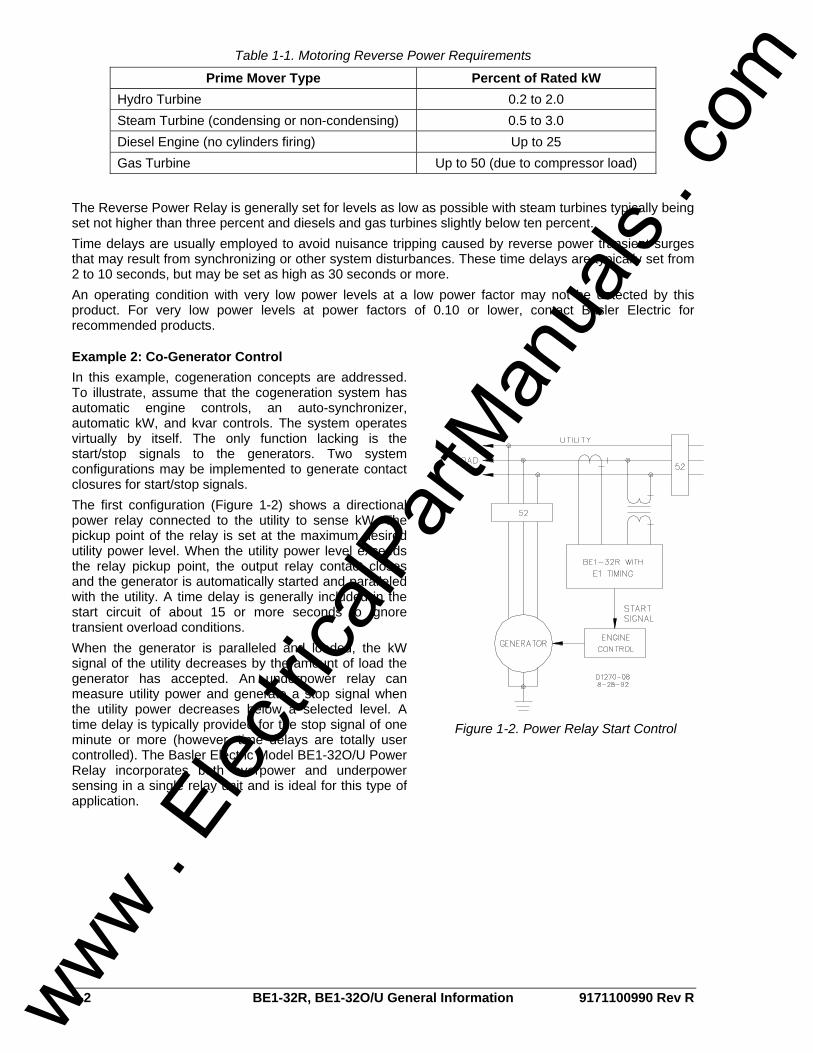
Table 1-1. Motoring Reverse Power Requirements
Prime Mover Type Percent of Rated kW Hydro Turbine 0.2 to 2.0 Steam Turbine (condensing or non-condensing) 0.5 to 3.0 Diesel Engine (no cylinders firing) Up to 25 Gas Turbine Up to 50 (due to compressor load)
The Reverse Power Relay is generally set for levels as low as possible with steam turbines typically being set not higher than three percent and diesels and gas turbines slightly below ten percent. Time delays are usually employed to avoid nuisance tripping caused by reverse power transient surges that may result from synchronizing or other system disturbances. These time delays are typically set from 2 to 10 seconds, but may be set as high as 30 seconds or more. An operating condition with very low power levels at a low power factor may not be detected by this product. For very low power levels at power factors of 0.10 or lower, contact Basler Electric for recommended products.
Example 2: Co-Generator Control In this example, cogeneration concepts are addressed. To illustrate, assume that the cogeneration system has automatic engine controls, an auto-synchronizer, automatic kW, and kvar controls. The system operates virtually by itself. The only function lacking is the start/stop signals to the generators. Two system configurations may be implemented to generate contact closures for start/stop signals. The first configuration (Figure 1-2) shows a directional power relay connected to the utility to sense kW. The pickup point of the relay is set at the maximum desired utility power level. When the utility power level exceeds the relay pickup point, the output relay contact closes and the generator is automatically started and paralleled with the utility. A time delay is generally included in the start circuit of about 15 or more seconds to ignore transient overload conditions. When the generator is paralleled and loaded, the kW signal of the utility decreases by the amount of load the generator has accepted. An underpower relay can measure utility power and generate a stop signal when the utility power decreases below a selected level. A time delay is typically provided for the stop signal of one minute or more (however, time delays are totally user controlled). The Basler Electric Model BE1-32O/U Power Relay incorporates both overpower and underpower sensing in a single relay unit and is ideal for this type of application.
Figure 1-2. Power Relay Start Control
www . El
ectric
alPar
tMan
uals
. com

9171100990 Rev R BE1-32R, BE1-32O/U General Information 1-3
In the second configuration, the start signal is generated in the same manner as that of Figure 1-2. The start signal setpoint may be set above the import power setting. The stop signal will require an underpower relay on the generator output. This system is illustrated in Figure 1-3.
Example 3: Generator Overload When excessive load has been connected to a generating system, the directional power relay can initiate corrective action. Corrective action could be energizing an alarm to alert the station operator. For automated systems, corrective action could be initiating the sequence to either shed non-critical load or to start and parallel an in-house generator to assume the excess load.
Figure 1-3. Power Relay Start/Stop Control
Example 4: Intertie Another typical use of the directional power relay, addresses excessive load and concerns distribution protection (Figure 1-4). A high voltage bus supplies two transformers: T1 and T2. Both T1 and T2 can supply all connected load. However, neither T1 nor T2 alone can supply the total load. A BE1-32O/U, over/underpower directional relay can protect this distribution system by providing overload protection for each transformer (overpower function) or by sensing power flow through the transformers (reverse power function) in an undesired direction.
Figure 1-4. Power Relay Distribution Protection
www . El
ectric
alPar
tMan
uals
. com
1-4 BE1-32R, BE1-32O/U General Information 9171100990 Rev R
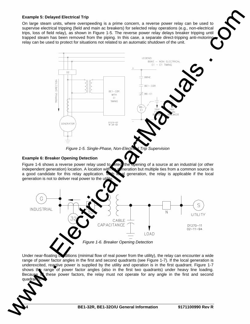
Example 5: Delayed Electrical Trip On large steam units, where overspeeding is a prime concern, a reverse power relay can be used to supervise electrical tripping (field and main ac breakers) for selected relay operations (e.g., non-electrical trips, loss of field relay), as shown in Figure 1-5. The reverse power relay delays breaker tripping until trapped steam has been removed from the piping. In this case, a separate direct-tripping anti-motoring relay can be used to protect for situations not related to an automatic shutdown of the unit.
Figure 1-5. Single-Phase, Non-Electrical Trip Supervision
Example 6: Breaker Opening Detection Figure 1-6 shows a reverse power relay used to detect the opening of a source at an industrial (or other independent generation) location. A location with no generation but multiple ties from a common source is a good candidate for this relay application. With local generation, the relay is applicable if the local generation is not to deliver real power to the utility.
Figure 1-6. Breaker Opening Detection
Under near-floating conditions (minimal flow of real power from the utility), the relay can encounter a wide range of power factor angles in the first and second quadrants (see Figure 1-7). If the local generation is underexcited, reactive power is supplied by the utility and operation is in the first quadrant. Figure 1-7 shows the range of power factor angles (also in the first two quadrants) under heavy line loading. Because of these power factors, the relay must not operate for any angle in the first and second quadrants.
www . El
ectric
alPar
tMan
uals
. com
9171100990 Rev R BE1-32R, BE1-32O/U General Information 1-5
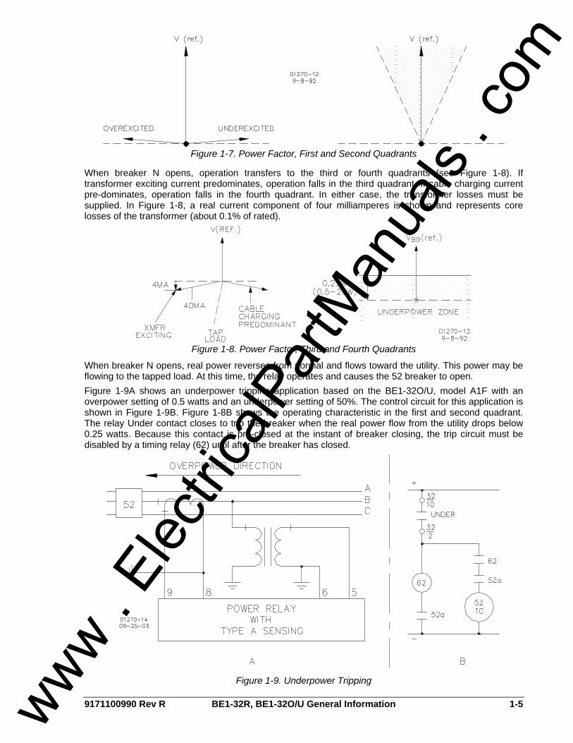
Figure 1-7. Power Factor, First and Second Quadrants
When breaker N opens, operation transfers to the third or fourth quadrants (see Figure 1-8). If transformer exciting current predominates, operation falls in the third quadrant. If cable charging current pre-dominates, operation falls in the fourth quadrant. In either case, the transformer losses must be supplied. In Figure 1-8, a real current component of four milliamperes is shown and represents core losses of the transformer (about 0.1% of rated).
Figure 1-8. Power Factor, Third and Fourth Quadrants
When breaker N opens, real power reverses from normal and flows toward the utility. This power may be flowing to the tapped load. At this time, the relay operates and causes the 52 breaker to open. Figure 1-9A shows an underpower tripping application based on the BE1-32O/U, model A1F with an overpower setting of 0.5 watts and an underpower setting of 50%. The control circuit for this application is shown in Figure 1-9B. Figure 1-8B shows the operating characteristic in the first and second quadrant. The relay Under contact closes to trip the breaker when the real power flow from the utility drops below 0.25 watts. Because this contact is pre-closed at the instant of breaker closing, the trip circuit must be disabled by a timing relay (62) until after the breaker has closed.
Figure 1-9. Underpower Tripping
www . El
ectric
alPar
tMan
uals
. com

1-6 BE1-32R, BE1-32O/U General Information 9171100990 Rev R
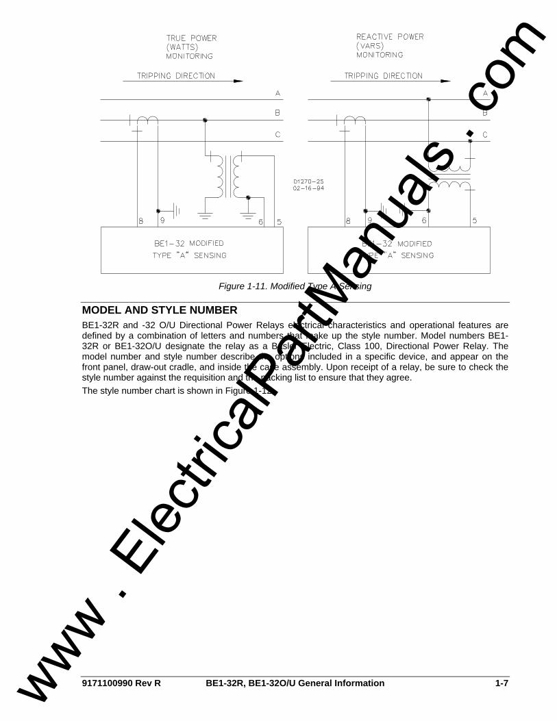
Example 7: Reactive Power (Vars) Detection This example illustrates a directional power relay configured to distinguish between real and reactive power. Real power (watts) is supplied to the synchronous generator by the prime mover, and reactive power (vars) is supplied to the field by the exciter. When field excitation is significantly reduced and the connected system can provide sufficient reactive power to maintain the generator terminal voltage, reactive power flows into the machine and causes it to operate as an induction generator with essentially the same kW output. This situation causes two major problems. First, the additional reactive loading of the faulty generator must be redistributed to other synchronous generators on the system. Secondly, a synchronous generator is not designed to operate as an induction generator. Excessive heating results in the damper (amortisseur) windings, slot wedges, and in the surface iron of the rotor due to the slip frequency current flow when a synchronous generator is operated as an induction generator. BE1-32R and BE1-32O/U Directional Power Relays are designed to respond to true power (P) as defined by the following equation and illustrated in Figure 1-10. P = EI (cos θ) where: P = real power (watts) I = effective current E = effective EMF or system voltage θ = the power factor angle However, reactive power (Q) is defined by the equation: Q = EI (sin θ) Using the trigonometric identity sine θ = cos(θ – 90 ) then: Q = EI (cos(θ – 90 )) If the phase of the sensed voltage is shifted +90 , the true power relay can be used to monitor reactive power. In practice, this can be accomplished by applying the appropriate line-to-line voltage to a true power measuring relay designed for line-to-neutral sensing. Figure 1-11 illustrates how a single-phase BE1-32R or BE1-32O/U can be connected to measure either real power (watts) or reactive power (vars) flow in a three-phase system. Note the difference of phase relationship between the alternate connections in Figure 1-11.
Figure 1-10. True Power Response
www . El
ectric
alPar
tMan
uals
. com
9171100990 Rev R BE1-32R, BE1-32O/U General Information 1-7
Figure 1-11. Modified Type A Sensing
MODEL AND STYLE NUMBER BE1-32R and -32 O/U Directional Power Relays electrical characteristics and operational features are defined by a combination of letters and numbers that make up the style number. Model numbers BE1-32R or BE1-32O/U designate the relay as a Basler Electric, Class 100, Directional Power Relay. The model number and style number describe the options included in a specific device, and appear on the front panel, draw-out cradle, and inside the case assembly. Upon receipt of a relay, be sure to check the style number against the requisition and the packing list to ensure that they agree. The style number chart is shown in Figure 1-12.
www . El
ectric
alPar
tMan
uals
. com
1-8 BE1-32R, BE1-32O/U General Information 9171100990 Rev R
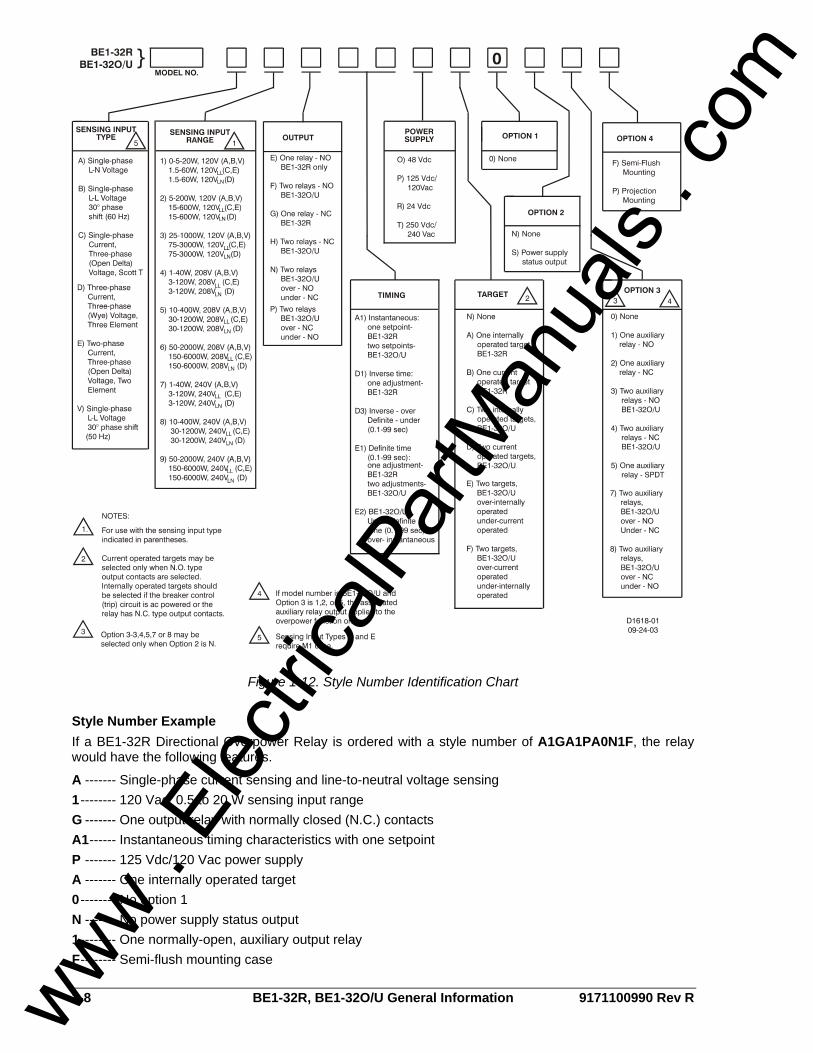
Figure 1-12. Style Number Identification Chart
Style Number Example If a BE1-32R Directional Overpower Relay is ordered with a style number of A1GA1PA0N1F, the relay would have the following features.
A ------- Single-phase current sensing and line-to-neutral voltage sensing 1-------- 120 Vac, 0.5 to 20 W sensing input range G ------- One output relay with normally closed (N.C.) contacts A1------ Instantaneous timing characteristics with one setpoint P ------- 125 Vdc/120 Vac power supply A ------- One internally operated target 0-------- No option 1 N ------- No power supply status output 1-------- One normally-open, auxiliary output relay F-------- Semi-flush mounting case
www . El
ectric
alPar
tMan
uals
. com
9171100990 Rev R BE1-32R, BE1-32O/U General Information 1-9
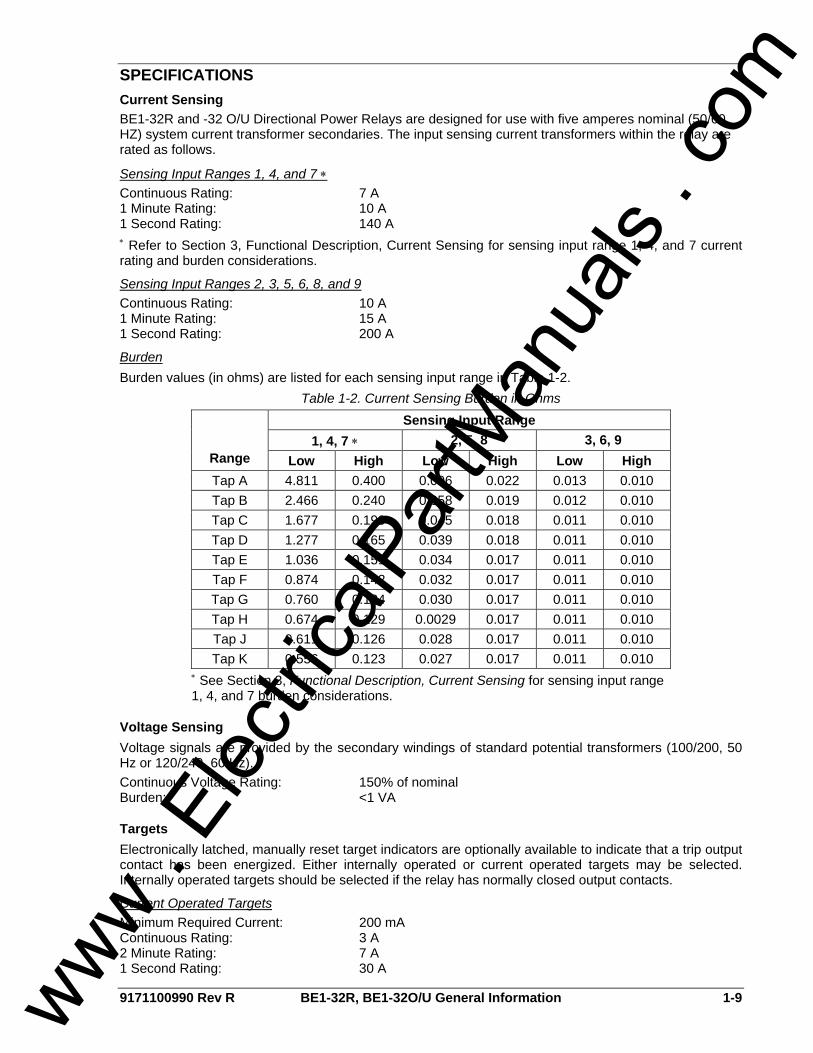
SPECIFICATIONS Current Sensing BE1-32R and -32 O/U Directional Power Relays are designed for use with five amperes nominal (50/60 HZ) system current transformer secondaries. The input sensing current transformers within the relay are rated as follows.
Sensing Input Ranges 1, 4, and 7 ∗ Continuous Rating: 7 A 1 Minute Rating: 10 A 1 Second Rating: 140 A ∗ Refer to Section 3, Functional Description, Current Sensing for sensing input range 1, 4, and 7 current rating and burden considerations.
Sensing Input Ranges 2, 3, 5, 6, 8, and 9 Continuous Rating: 10 A 1 Minute Rating: 15 A 1 Second Rating: 200 A
Burden Burden values (in ohms) are listed for each sensing input range in Table 1-2.
Table 1-2. Current Sensing Burden in Ohms Sensing Input Range
1, 4, 7 ∗ 2, 5, 8 3, 6, 9 Range Low High Low High Low High Tap A 4.811 0.400 0.096 0.022 0.013 0.010 Tap B 2.466 0.240 0.058 0.019 0.012 0.010 Tap C 1.677 0.190 0.045 0.018 0.011 0.010 Tap D 1.277 0.165 0.039 0.018 0.011 0.010 Tap E 1.036 0.151 0.034 0.017 0.011 0.010 Tap F 0.874 0.142 0.032 0.017 0.011 0.010 Tap G 0.760 0.134 0.030 0.017 0.011 0.010 Tap H 0.674 0.129 0.0029 0.017 0.011 0.010 Tap J 0.611 0.126 0.028 0.017 0.011 0.010 Tap K 0.556 0.123 0.027 0.017 0.011 0.010
∗ See Section 3, Functional Description, Current Sensing for sensing input range 1, 4, and 7 burden considerations.
Voltage Sensing Voltage signals are provided by the secondary windings of standard potential transformers (100/200, 50 Hz or 120/240, 60 Hz). Continuous Voltage Rating: 150% of nominal Burden: <1 VA
Targets Electronically latched, manually reset target indicators are optionally available to indicate that a trip output contact has been energized. Either internally operated or current operated targets may be selected. Internally operated targets should be selected if the relay has normally closed output contacts.
Current Operated Targets Minimum Required Current: 200 mA Continuous Rating: 3 A 2 Minute Rating: 7 A 1 Second Rating: 30 A
www . El
ectric
alPar
tMan
uals
. com
1-10 BE1-32R, BE1-32O/U General Information 9171100990 Rev R
Output Circuits
Resistive Ratings 120 Vac: Make, break, and carry 7 Aac continuously 250 Vdc: Make and carry 30 Adc for 0.2 s, carry 7 Adc continuously, and break 0.3 Adc 500 Vdc: Make and carry 15 Adc for 0.2 s, carry 7 Adc continuously, and break 0.3 Adc
Inductive Ratings 120 Vac, 125 Vdc, 250 Vdc: Break 0.3 A (L/R = 0.04)
Power Supply Power supply specifications are listed in Table 1-3. All ac references are at 50/60 Hz.
Table 1-3. Power Supply Specifications
Input Voltage Type
Nominal Range Burden at Nominal
O (mid range) 48 Vdc 24 to 150 Vdc 3.6 W
P (mid range) 125 Vdc 120 Vac
24 to 150 Vdc 90 to 132 Vac
3.7 W 17.3 VA
R (low range) 24 Vdc 12 to 32 Vdc ∗ 3.7 W
T (high range) 250 Vdc 240 Vac
68 to 280 Vdc 90 to 270 Vac
3.8 W 24.6 VA
∗ Type R power supply may require 14 Vdc to begin operation. Once operating, the voltage may be reduced to 12 Vdc.
Pickup
Single-Phase Accuracy PF = 1: ±2 percent of front panel setting or 0.05 W, whichever is greater 0.5<PF<1: ±5 percent of front panel setting or 0.05 W, whichever is greater
Three-Phase Accuracy PF =1 ±2 percent of front panel setting or 0.15 W, whichever is greater 0.5<PF<1 ±5 percent of front panel setting or 0.15 W, whichever is greater This product is not recommended for power factors below 0.10. Contact Basler Electric for recommended products.
Dropout Accuracy 95% of actual pickup.
Timing
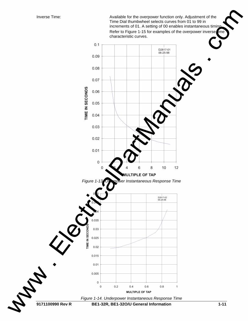
Response Time Instantaneous Overpower: <80 ms (60 Hz) or <100 ms (50 Hz) for real power magnitude of
2 times the setting and greater. The response time is character-ized by the graph in Figure 1-13.
Instantaneous Underpower: <50 ms (60 Hz) or <65 ms (50 Hz) for real power magnitude of 0.8 times the setting and less. The response time is character-ized by the graph in Figure 1-14.
Adjustment Range Definite Time: Thumbwheel adjustable over the range of 0.1 to 9.9 seconds in
increments of 0.1 seconds or by use of a multiplier switch, 1 to 99 seconds in increments of 01 seconds. A setting of 00 enables instantaneous timing.
www . El
ectric
alPar
tMan
uals
. com
9171100990 Rev R BE1-32R, BE1-32O/U General Information 1-11
Inverse Time: Available for the overpower function only. Adjustment of the Time Dial thumbwheel selects curves from 01 to 99 in increments of 01. A setting of 00 enables instantaneous timing.
Refer to Figure 1-15 for examples of the overpower inverse time characteristic curves.
Figure 1-13. Overpower Instantaneous Response Time
Figure 1-14. Underpower Instantaneous Response Time www .
Elec
tricalP
artM
anua
ls . c
om

1-12 BE1-32R, BE1-32O/U General Information 9171100990 Rev R
Figure 1-15. Overpower Inverse Time Characteristic Curves
www . El
ectric
alPar
tMan
uals
. com
9171100990 Rev R BE1-32R, BE1-32O/U General Information 1-13
Timing—continued
Accuracy Instantaneous: <80 ms (60 Hz) or <100 ms, (50 Hz) up to a real power
magnitude of 2 times the setting Definite: ±5 percent or 50 ms, whichever is greater Inverse: +5 percent or 50 ms, whichever is greater NOTE: Operating time is repeatable within 2% or 50 ms
(whichever is greater) for any combination of time dial and power settings within the specified operating temperature range.
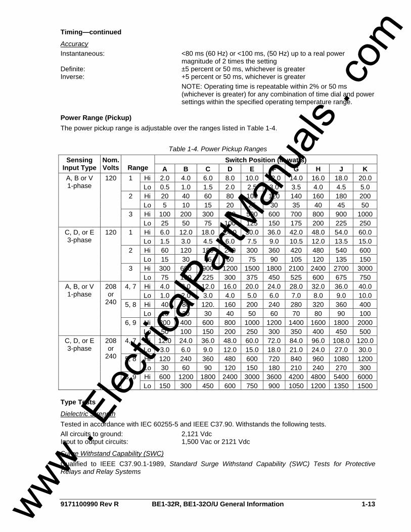
Power Range (Pickup) The power pickup range is adjustable over the ranges listed in Table 1-4.
Table 1-4. Power Pickup Ranges Switch Position (in watts) Sensing
Input Type Nom. Volts Range A B C D E F G H J K
Hi 2.0 4.0 6.0 8.0 10.0 12.0 14.0 16.0 18.0 20.0 1 Lo 0.5 1.0 1.5 2.0 2.5 3.0 3.5 4.0 4.5 5.0 Hi 20 40 60 80 100 120 140 160 180 200 2 Lo 5 10 15 20 25 30 35 40 45 50 Hi 100 200 300 400 500 600 700 800 900 1000
A, B or V 1-phase
120
3 Lo 25 50 75 100 125 150 175 200 225 250 Hi 6.0 12.0 18.0 24.0 30.0 36.0 42.0 48.0 54.0 60.0 1 Lo 1.5 3.0 4.5 6.0 7.5 9.0 10.5 12.0 13.5 15.0 Hi 60 120 180 240 300 360 420 480 540 600 2 Lo 15 30 45 60 75 90 105 120 135 150 Hi 300 600 900 1200 1500 1800 2100 2400 2700 3000
C, D, or E 3-phase
120
3 Lo 75 150 225 300 375 450 525 600 675 750 Hi 4.0 8.0 12.0 16.0 20.0 24.0 28.0 32.0 36.0 40.0 4, 7 Lo 1.0 2.0 3.0 4.0 5.0 6.0 7.0 8.0 9.0 10.0 Hi 40 80 120. 160 200 240 280 320 360 400 5, 8 Lo 10 20 30 40 50 60 70 80 90 100 Hi 200 400 600 800 1000 1200 1400 1600 1800 2000
A, B, or V 1-phase
208 or
240
6, 9 Lo 50 100 150 200 250 300 350 400 450 500 Hi 12.0 24.0 36.0 48.0 60.0 72.0 84.0 96.0 108.0 120.04, 7 Lo 3.0 6.0 9.0 12.0 15.0 18.0 21.0 24.0 27.0 30.0 Hi 120 240 360 480 600 720 840 960 1080 1200 5, 8 Lo 30 60 90 120 150 180 210 240 270 300 Hi 600 1200 1800 2400 3000 3600 4200 4800 5400 6000
C, D, or E 3-phase
208 or
240
6, 9 Lo 150 300 450 600 750 900 1050 1200 1350 1500
Type Tests
Dielectric Strength Tested in accordance with IEC 60255-5 and IEEE C37.90. Withstands the following tests. All circuits to ground: 2,121 Vdc Input to output circuits: 1,500 Vac or 2121 Vdc
Surge Withstand Capability (SWC) Qualified to IEEE C37.90.1-1989, Standard Surge Withstand Capability (SWC) Tests for Protective Relays and Relay Systems
www . El
ectric
alPar
tMan
uals
. com
1-14 BE1-32R, BE1-32O/U General Information 9171100990 Rev R
Radio Frequency Interference Maintains proper operation when tested for interference in accordance with IEEE C37.90.2-1987, Standard Withstand Capability of Relay Systems to Radiated Electromagnetic Interference from Transceivers.
Shock In standardized testing, the relay has withstood 15 G in each of three mutually perpendicular planes without structural damage or degradation of performance.
Vibration In standardized testing, the relay has withstood 2 G in each of three mutually perpendicular planes, swept over the range of 10 to 500 Hz for a total of six sweeps, 15 minutes each sweep, without structural damage or degradation of performance.
UL Recognition Recognized per Standard 508, file number E97033. Note: Output contacts are not UL recognized for voltages greater than 250 volts.
GOST-R GOST-R certified No. POCC US.ME05.B03391; complies with the relevant standards of Gosstandart of Russia. Issued by accredited certification body POCC RU.0001.11ME05.
Temperature Operating: –40°C to 70°C (–40°F to 158°F) Storage: –65°C to 100°C (–85°F to 212°F)
Weight S1 Configuration: 13.5 lb (6.12 kg) maximum M1 Configuration: 18.5 lb (8.39 kg) maximum
www . El
ectric
alPar
tMan
uals
. com

9171100990 Rev R BE1-32R, BE1-32O/U Controls and Indicators 2-1
SECTION 2 • CONTROLS AND INDICATORS INTRODUCTION All BE1-32R and BE1-32O/U controls and indicators are located on the front panel. The controls and indicators are shown in Figure 2-1 and described in Table 2-1. Figure 2-1 illustrates a relay with the maximum number of controls and indicators. Your relay may not have all of the controls and indicators shown here.
Figure 2-1. Controls and Indicators
www . El
ectric
alPar
tMan
uals
. com

2-2 BE1-32R, BE1-32O/U Controls and Indicators 9171100990 Rev R
Table 2-1. Control and Indicator Descriptions
Locator Description
A Range Select Switch. This two-position switch is used in conjunction with the Overpower Tap Selector (locator C) and selects either the high or low overpower pickup range.
B Overpower Time Delay Control. These thumbwheel switches select the overpower trip time delay. For relays with definite timing, these switches are used in conjunction with the Overpower Time Delay Multiplier Switch (locator E) to select the overpower trip time delay.
C Overpower Tap Selector. This rotary switch is used in conjunction with the Range Select Switch (locator A) and selects the overpower pickup point. The tap settings correspond to the power levels listed in the Tap Select Range Chart (locator M).
D Overpower Pickup Indicator. This light emitting diode (LED) lights when the power level exceeds the setting of the Overpower Tap Selector (locator C) and Range Select Switch (locator A).
E Overpower Time Delay Multiplier Switch. This two-position switch selects the multiplier (0.1 or 1.0) applied to the definite time setting of the Overpower Time Delay Control (locator B).
F Underpower Time Delay Control. These thumbwheel switches select the underpower trip time delay. For relays with definite timing, these switches are used in conjunction with the Underpower Time Delay Multiplier Switch (locator J) to select the underpower trip time delay.
G Underpower Pickup Selector. This potentiometer control adjusts the underpower pickup level from 10 to 95 percent of the overpower pickup setting.
H Power Indicator. This LED lights when operating power is applied to the relay.
I Underpower Pickup Indicator. This LED lights when the power level decreases below the setting of the Underpower Pickup Selector (locator G).
J Underpower Time Delay Multiplier Switch. This two-position switch selects the multiplier (0.1 or 1.0) applied to the definite time setting of the Underpower Time Delay Control (locator F).
K Target Reset Switch. Operating this switch resets the electronically latched target indicators.
L Target Indicators. The electronically latched red target indicators illuminate when the corresponding output relay energizes. The targets are reset by operating the Target Reset Switch (locator K).
M Tap Selection Chart. This chart indicates the Overpower Tap Selector and Range Select Switch positions required to initiate an overpower trip at the listed power levels.
N Output Test Pushbuttons. These pushbuttons allow manual actuation of the output relays. Output relay actuation is achieved by inserting a nonconductive rod through the front panel access holes.
www . El
ectric
alPar
tMan
uals
. com

9171100990 Rev R BE1-32R, BE1-32O/U Functional Description i
SECTION 3 • FUNCTIONAL DESCRIPTION TABLE OF CONTENTS
SECTION 3 • FUNCTIONAL DESCRIPTION ........................................................................................... 3-1
INTRODUCTION.................................................................................................................................... 3-1 Current Sensing ................................................................................................................................. 3-1 Phase Rotation Sensitivity.................................................................................................................. 3-1 Sensing Input Types........................................................................................................................... 3-3 KW Transducer................................................................................................................................... 3-5 Comparator Circuits ........................................................................................................................... 3-5 Pickup................................................................................................................................................. 3-5 Timing................................................................................................................................................. 3-6 Outputs ............................................................................................................................................... 3-7 Output Test Pushbuttons.................................................................................................................... 3-7 Power Supply ..................................................................................................................................... 3-7 Target Indicators ................................................................................................................................ 3-7
Figures Figure 3-1. Function Block Diagram.......................................................................................................... 3-1 Figure 3-2. Type E Sensing with ABC Rotation ........................................................................................ 3-2 Figure 3-3. Type E Sensing with ACB Rotation ........................................................................................ 3-2 Figure 3-4. Type B or V Sensing with ABC Rotation................................................................................. 3-2 Figure 3-5. Type B or V Sensing with ACB Rotation................................................................................. 3-3 Figure 3-6. Type A Sensing....................................................................................................................... 3-3 Figure 3-7. Type B/Type V Sensing .......................................................................................................... 3-4 Figure 3-8. Type C Sensing....................................................................................................................... 3-4 Figure 3-9. Type D Sensing....................................................................................................................... 3-5 Figure 3-10. Type E Sensing..................................................................................................................... 3-6
www . El
ectric
alPar
tMan
uals
. com

ii BE1-32R, BE1-32O/U Functional Description 9171100990 Rev R
This page intentionally left blank.
www . El
ectric
alPar
tMan
uals
. com
9171100990 Rev R BE1-32R, BE1-32O/U Functional Description 3-1
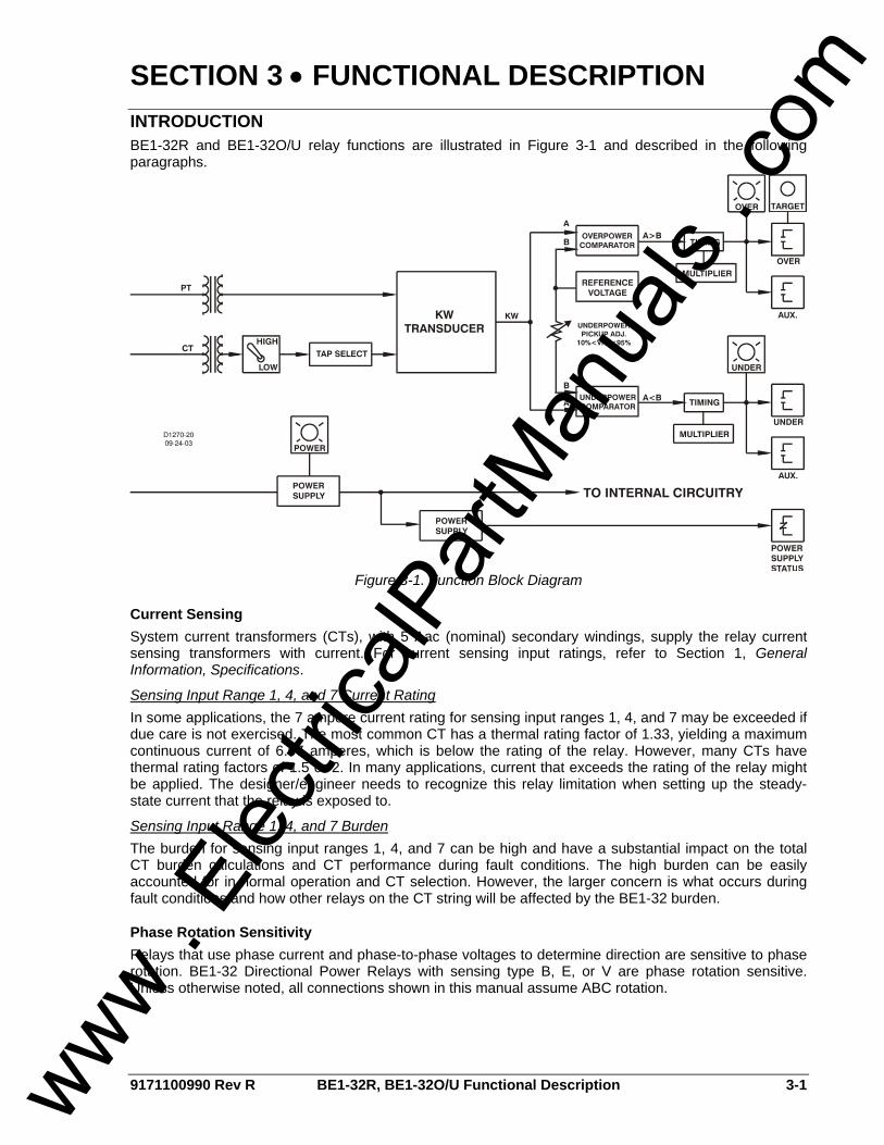
SECTION 3 • FUNCTIONAL DESCRIPTION INTRODUCTION BE1-32R and BE1-32O/U relay functions are illustrated in Figure 3-1 and described in the following paragraphs.
Figure 3-1. Function Block Diagram
Current Sensing System current transformers (CTs), with 5 Aac (nominal) secondary windings, supply the relay current sensing transformers with current. For current sensing input ratings, refer to Section 1, General Information, Specifications.
Sensing Input Range 1, 4, and 7 Current Rating In some applications, the 7 ampere current rating for sensing input ranges 1, 4, and 7 may be exceeded if due care is not exercised. The most common CT has a thermal rating factor of 1.33, yielding a maximum continuous current of 6.67 amperes, which is below the rating of the relay. However, many CTs have thermal rating factors of 1.5 or 2. In many applications, current that exceeds the rating of the relay might be applied. The designer/engineer needs to recognize this relay limitation when setting up the steady-state current that the relay is exposed to.
Sensing Input Range 1, 4, and 7 Burden The burden for sensing input ranges 1, 4, and 7 can be high and have a substantial impact on the total CT burden calculations and CT performance during fault conditions. The high burden can be easily accounted for in normal operation and CT selection. However, the larger concern is what occurs during fault conditions and how other relays on the CT string will be affected by the BE1-32 burden.
Phase Rotation Sensitivity Relays that use phase current and phase-to-phase voltages to determine direction are sensitive to phase rotation. BE1-32 Directional Power Relays with sensing type B, E, or V are phase rotation sensitive. Unless otherwise noted, all connections shown in this manual assume ABC rotation.
www . El
ectric
alPar
tMan
uals
. com
3-2 BE1-32R, BE1-32O/U Functional Description 9171100990 Rev R
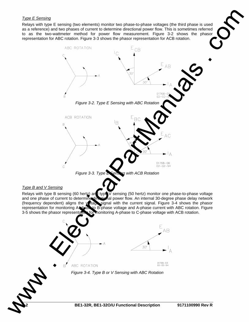
Type E Sensing Relays with type E sensing (two elements) monitor two phase-to-phase voltages (the third phase is used as a reference) and two phases of current to determine directional power flow. This is sometimes referred to as the two-wattmeter method for power flow measurement. Figure 3-2 shows the phasor representation for ABC rotation. Figure 3-3 shows the phasor representation for ACB rotation.
Figure 3-2. Type E Sensing with ABC Rotation
Figure 3-3. Type E Sensing with ACB Rotation
Type B and V Sensing Relays with type B sensing (60 hertz) and type V sensing (50 hertz) monitor one phase-to-phase voltage and one phase of current to determine directional power flow. An internal 30-degree phase delay network (frequency dependent) aligns the voltage signal with the current signal. Figure 3-4 shows the phasor representation for monitoring A-phase to B-phase voltage and A-phase current with ABC rotation. Figure 3-5 shows the phasor representation for monitoring A-phase to C-phase voltage with ACB rotation.
Figure 3-4. Type B or V Sensing with ABC Rotation
www . El
ectric
alPar
tMan
uals
. com
9171100990 Rev R BE1-32R, BE1-32O/U Functional Description 3-3
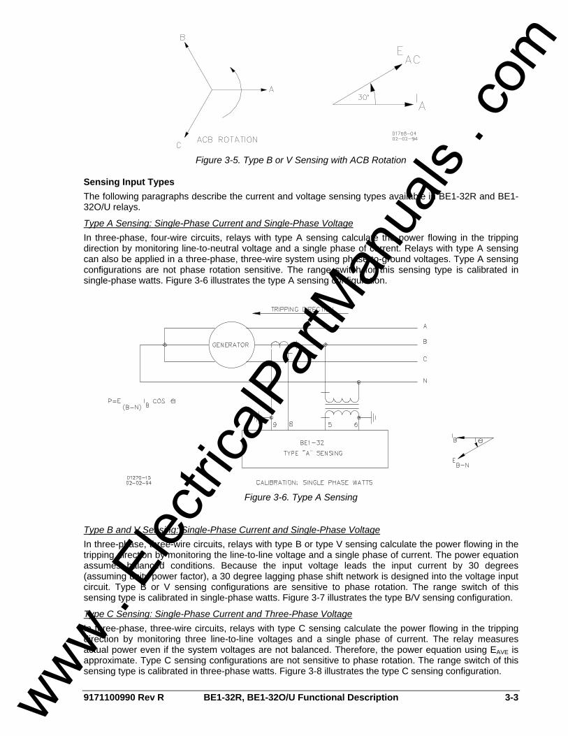
Figure 3-5. Type B or V Sensing with ACB Rotation
Sensing Input Types The following paragraphs describe the current and voltage sensing types available in BE1-32R and BE1-32O/U relays.
Type A Sensing: Single-Phase Current and Single-Phase Voltage In three-phase, four-wire circuits, relays with type A sensing calculate the power flowing in the tripping direction by monitoring line-to-neutral voltage and a single phase of current. Relays with type A sensing can also be applied in a three-phase, three-wire system using phase-to-ground voltages. Type A sensing configurations are not phase rotation sensitive. The range switch for this sensing type is calibrated in single-phase watts. Figure 3-6 illustrates the type A sensing configuration.
Figure 3-6. Type A Sensing
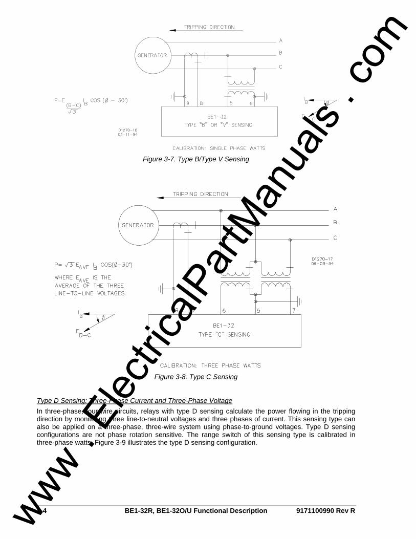
Type B and V Sensing: Single-Phase Current and Single-Phase Voltage In three-phase, three-wire circuits, relays with type B or type V sensing calculate the power flowing in the tripping direction by monitoring the line-to-line voltage and a single phase of current. The power equation assumes balanced conditions. Because the input voltage leads the input current by 30 degrees (assuming unity power factor), a 30 degree lagging phase shift network is designed into the voltage input circuit. Type B or V sensing configurations are sensitive to phase rotation. The range switch of this sensing type is calibrated in single-phase watts. Figure 3-7 illustrates the type B/V sensing configuration.
Type C Sensing: Single-Phase Current and Three-Phase Voltage In three-phase, three-wire circuits, relays with type C sensing calculate the power flowing in the tripping direction by monitoring three line-to-line voltages and a single phase of current. The relay measures actual power even if the system voltages are not balanced. Therefore, the power equation using EAVE is approximate. Type C sensing configurations are not sensitive to phase rotation. The range switch of this sensing type is calibrated in three-phase watts. Figure 3-8 illustrates the type C sensing configuration.
www . El
ectric
alPar
tMan
uals
. com
3-4 BE1-32R, BE1-32O/U Functional Description 9171100990 Rev R
Figure 3-7. Type B/Type V Sensing
Figure 3-8. Type C Sensing
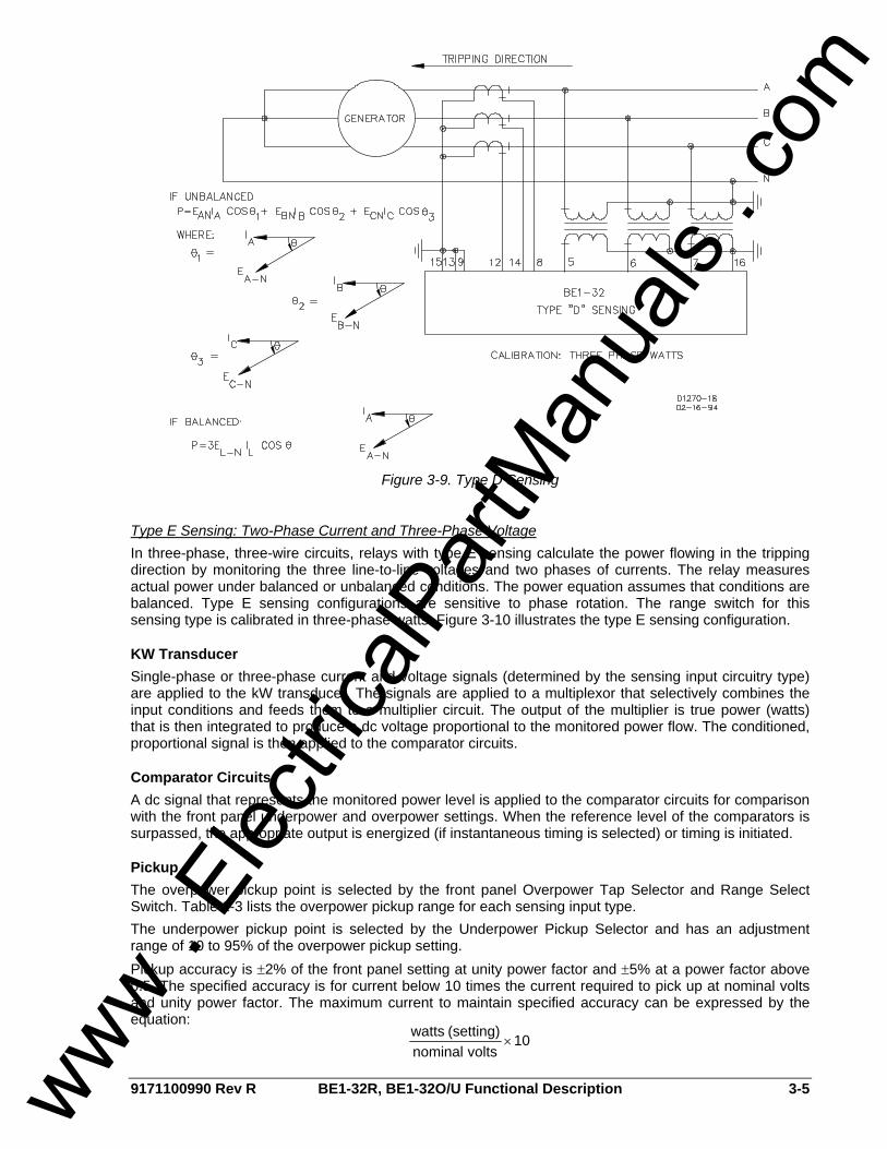
Type D Sensing: Three-Phase Current and Three-Phase Voltage In three-phase, four-wire circuits, relays with type D sensing calculate the power flowing in the tripping direction by monitoring three line-to-neutral voltages and three phases of current. This sensing type can also be applied on a three-phase, three-wire system using phase-to-ground voltages. Type D sensing configurations are not phase rotation sensitive. The range switch of this sensing type is calibrated in three-phase watts. Figure 3-9 illustrates the type D sensing configuration.
www . El
ectric
alPar
tMan
uals
. com
9171100990 Rev R BE1-32R, BE1-32O/U Functional Description 3-5
Figure 3-9. Type D Sensing
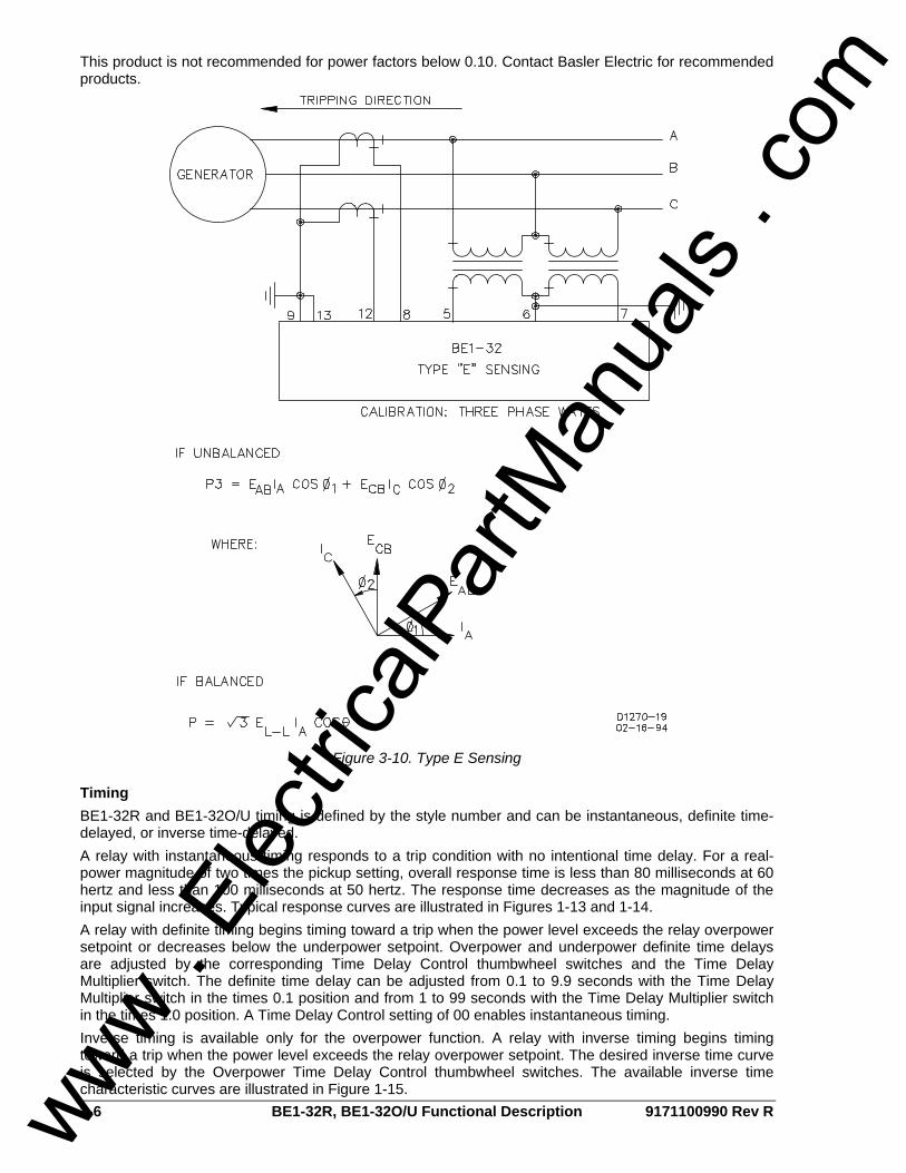
Type E Sensing: Two-Phase Current and Three-Phase Voltage In three-phase, three-wire circuits, relays with type E sensing calculate the power flowing in the tripping direction by monitoring the three line-to-line voltages and two phases of currents. The relay measures actual power under balanced or unbalanced conditions. The power equation assumes that conditions are balanced. Type E sensing configurations are sensitive to phase rotation. The range switch for this sensing type is calibrated in three-phase watts. Figure 3-10 illustrates the type E sensing configuration.
KW Transducer Single-phase or three-phase current and voltage signals (determined by the sensing input circuitry type) are applied to the kW transducer. The signals are applied to a multiplexor that selectively combines the input conditions and feeds them to a multiplier circuit. The output of the multiplier is true power (watts) that is then integrated to produce a dc voltage proportional to the monitored power flow. The conditioned, proportional signal is then applied to the comparator circuits.
Comparator Circuits A dc signal that represents the monitored power level is applied to the comparator circuits for comparison with the front panel underpower and overpower settings. When the reference level of the comparators is surpassed, the appropriate output is energized (if instantaneous timing is selected) or timing is initiated.
Pickup The overpower pickup point is selected by the front panel Overpower Tap Selector and Range Select Switch. Table 1-3 lists the overpower pickup range for each sensing input type. The underpower pickup point is selected by the Underpower Pickup Selector and has an adjustment range of 10 to 95% of the overpower pickup setting. Pickup accuracy is ±2% of the front panel setting at unity power factor and ±5% at a power factor above 0.5. The specified accuracy is for current below 10 times the current required to pick up at nominal volts and unity power factor. The maximum current to maintain specified accuracy can be expressed by the equation:
10voltsnominal
(setting) watts×
www . El
ectric
alPar
tMan
uals
. com
3-6 BE1-32R, BE1-32O/U Functional Description 9171100990 Rev R
This product is not recommended for power factors below 0.10. Contact Basler Electric for recommended products.
Figure 3-10. Type E Sensing
Timing BE1-32R and BE1-32O/U timing is defined by the style number and can be instantaneous, definite time-delayed, or inverse time-delayed. A relay with instantaneous timing responds to a trip condition with no intentional time delay. For a real-power magnitude of two times the pickup setting, overall response time is less than 80 milliseconds at 60 hertz and less than 100 milliseconds at 50 hertz. The response time decreases as the magnitude of the input signal increases. Typical response curves are illustrated in Figures 1-13 and 1-14. A relay with definite timing begins timing toward a trip when the power level exceeds the relay overpower setpoint or decreases below the underpower setpoint. Overpower and underpower definite time delays are adjusted by the corresponding Time Delay Control thumbwheel switches and the Time Delay Multiplier switch. The definite time delay can be adjusted from 0.1 to 9.9 seconds with the Time Delay Multiplier switch in the times 0.1 position and from 1 to 99 seconds with the Time Delay Multiplier switch in the times 1.0 position. A Time Delay Control setting of 00 enables instantaneous timing. Inverse timing is available only for the overpower function. A relay with inverse timing begins timing toward a trip when the power level exceeds the relay overpower setpoint. The desired inverse time curve is selected by the Overpower Time Delay Control thumbwheel switches. The available inverse time characteristic curves are illustrated in Figure 1-15.
www . El
ectric
alPar
tMan
uals
. com

9171100990 Rev R BE1-32R, BE1-32O/U Functional Description 3-7
Outputs BE1-32R and BE1-32O/U relay outputs are divided into three categories: Overpower and Underpower, Auxiliary, and Power Supply Status.
Overpower and Underpower Outputs A dedicated output relay is provided for each overpower and underpower protection function. The BE1-32R is equipped with a set of overpower output contacts that are configured as normally-open (NO) or normally-closed (NC). The BE1-32O/U is equipped with a set of overpower output contacts and a set of underpower output contacts. The BE1-32O/U outputs may be any combination of NO or NC contact configurations. Output contact configuration is determined by the output digit of the relay style number.
Auxiliary Outputs Auxiliary output contacts are supplied when specified by the Option 3 digit of the relay style number. Auxiliary outputs are provided for both overpower and underpower protection functions. The auxiliary output contacts may be NO, NC, or single-pole, double-throw (SPDT).
Power Supply Status Output The power supply status relay has a set of NC contacts and energizes when operating power is applied to the BE1-32R or BE1-32O/U. If either side of the power supply output (+12 Vdc or –12 Vdc) fails, the power supply status relay de-energizes and opens the power supply status output contacts. Shorting bars within the relay case short-circuit the power supply status output when the upper connection plug is withdrawn from the case.
Output Test Pushbuttons The output test pushbuttons allow testing of the overpower and underpower outputs and optional auxiliary outputs. To prevent accidental operation, the pushbuttons are recessed behind openings in the front panel. An output is tested by inserting a nonconductive rod through the access holes.
Power Supply Operating power for the relay circuitry is supplied by a wide-range, electrically isolated, low-burden power supply. The power supply operating power input is not polarity sensitive. The front panel Power Indicator and power supply status output indicate when the power supply is operating. Power supply specifications are listed in Table 1-3.
Target Indicators Target indicators are optional components selected when a relay is ordered. The electronically latched and reset targets consist of red LED indicators located on the relay front panel. A latched target is reset by operating the target reset switch on the front panel. If relay operating power is lost, any illuminated (latched) targets are extinguished. When relay operating power is restored, the previously latched targets are restored to their latched state. A relay can be equipped with either internally operated targets or current operated targets.
Internally Operated Targets The relay trip outputs are directly applied to drive the appropriate target indicator. Each indicator is illuminated regardless of the current level in the trip circuit.
Current Operated Targets A current operated target is triggered by closure of the corresponding output contact and the presence of at least 200 milliamperes of current flowing in the trip circuit.
NOTE Prior to September 2007, BE1-32 and BE1-32O/U target indicators consisted of magnetically-latched, disc indicators. These mechanically latched target indicators have been replaced by the electronically latched LED targets in use today.
www . El
ectric
alPar
tMan
uals
. com

3-8 BE1-32R, BE1-32O/U Functional Description 9171100990 Rev R
This page intentionally left blank.
www . El
ectric
alPar
tMan
uals
. com
9171100990 Rev R BE1-32R, BE1-32O/U Installation i
SECTION 4 • INSTALLATION TABLE OF CONTENTS
SECTION 4 • INSTALLATION .................................................................................................................. 4-1
INTRODUCTION.................................................................................................................................... 4-1 RELAY OPERATING GUIDELINES AND PRECAUTIONS .................................................................. 4-1 MOUNTING............................................................................................................................................ 4-1
Panel Drilling Diagrams and Outline Drawings .................................................................................. 4-1 CONNECTIONS .................................................................................................................................. 4-17
Notes for Figures 4-21 and 4-22 ...................................................................................................... 4-22 MAINTENANCE................................................................................................................................... 4-28
Repair ............................................................................................................................................... 4-28 Maintenance Accessories ................................................................................................................ 4-28
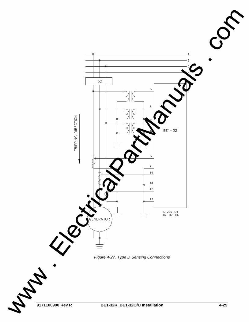
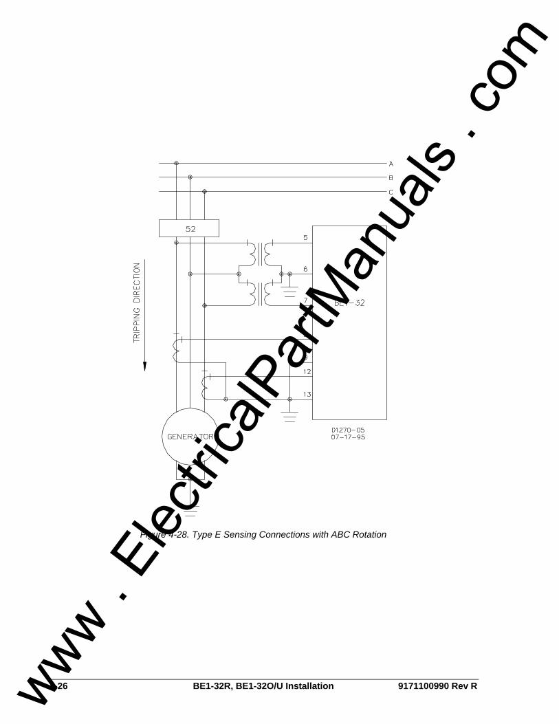
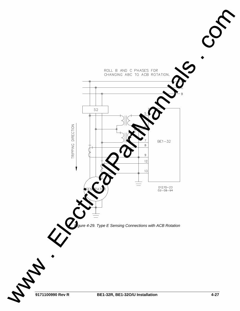
Figures Figure 4-1. Panel Drilling Diagram, S1 Case, Semi-Flush Mounting ........................................................ 4-2 Figure 4-2. Panel Drilling Diagram, S1 Case, Projection Mounting, Single-Ended................................... 4-3 Figure 4-3. Panel Drilling Diagram, S1 Case, Projection Mounting, Double-Ended ................................. 4-4 Figure 4-4. Panel Drilling Diagram, M1 Case, Semi-Flush Mounting........................................................ 4-5 Figure 4-5. Panel Drilling Diagram, M1 Case, Projection Mounting.......................................................... 4-6 Figure 4-6. Case Dimensions, S1 Case, Projection Mounting, Rear View ............................................... 4-7 Figure 4-7. Case Dimensions, M1 Case, Projection Mounting, Rear View............................................... 4-8 Figure 4-8. Case Dimensions, S1 Case, Semi-Flush Mounting, Single-Ended, Side View...................... 4-9 Figure 4-9. Case Dimensions, S1 Case, Semi-Flush Mounting, Double-Ended, Side View................... 4-10 Figure 4-10. Case Dimensions, S1 Case, Projection Mounting, Single-Ended, Side View .................... 4-11 Figure 4-11. Case Dimensions, S1 Case, Projection Mounting, Double-Ended, Side View................... 4-12 Figure 4-12. Case Dimensions, M1 Case, Semi-Flush Mounting, Side View ......................................... 4-13 Figure 4-13. Case Dimensions, M1 Case, Projection Mounting, Side View ........................................... 4-14 Figure 4-14. Cover Dimensions, S1 Case, Front View............................................................................ 4-15 Figure 4-15. Cover Dimensions, M1 Case, Front View........................................................................... 4-16 Figure 4-16. Control Circuit Diagram....................................................................................................... 4-17 Figure 4-17. Internal Connections, Sensing Type A, B, or V .................................................................. 4-18 Figure 4-18. Internal Connections, Sensing Type C ............................................................................... 4-19 Figure 4-19. Internal Connections, Sensing Type D ............................................................................... 4-20 Figure 4-20. Internal Connections, Sensing Type E................................................................................ 4-21 Figure 4-21. BE1-32R Typical External Connections.............................................................................. 4-22 Figure 4-22. BE1-32O/U Typical External Connections.......................................................................... 4-22 Figure 4-23. Type A Sensing Connections.............................................................................................. 4-23 Figure 4-24.Type B or V Sensing Connections with ABC Rotation......................................................... 4-23 Figure 4-25. Type B or V Sensing Connections with ACB Rotation........................................................ 4-24 Figure 4-26. Type C Sensing Connections ............................................................................................. 4-24 Figure 4-27. Type D Sensing Connections ............................................................................................. 4-25 Figure 4-28. Type E Sensing Connections with ABC Rotation ............................................................... 4-26 Figure 4-29. Type E Sensing Connections with ACB Rotation ............................................................... 4-27
www . El
ectric
alPar
tMan
uals
. com

ii BE1-32R, BE1-32O/U Installation 9171100990 Rev R
This page intentionally left blank.
www . El
ectric
alPar
tMan
uals
. com

9171100990 Rev R BE1-32R, BE1-32O/U Installation 4-1
SECTION 4 • INSTALLATION INTRODUCTION BE1-32R and BE1-32O/U relays are shipped in sturdy cartons to prevent damage during transit. Upon receipt of a relay, check the model and style number against the requisition and packing list to see that they agree. Inspect the relay for shipping damage. If there is evidence of damage, file a claim with the carrier and notify your sales representative or Basler Electric. If the relay will not be installed immediately, store it in its original shipping carton in a moisture- and dust-free environment. Before placing the relay in service, it is recommended that the test procedures of Section 5, Testing be performed.
RELAY OPERATING GUIDELINES AND PRECAUTIONS Before installing or operating the relay, note the following guidelines and precautions. • For proper current-operated target operation, a minimum current of 200 milliamperes must flow
through the output trip circuit. • If a wiring insulation test is required, remove the connection plugs and withdraw the relay from its
case.
MOUNTING Because the relay is of solid-state design, it does not have to mount vertically. Any convenient mounting angle may be chosen.
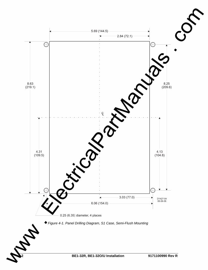
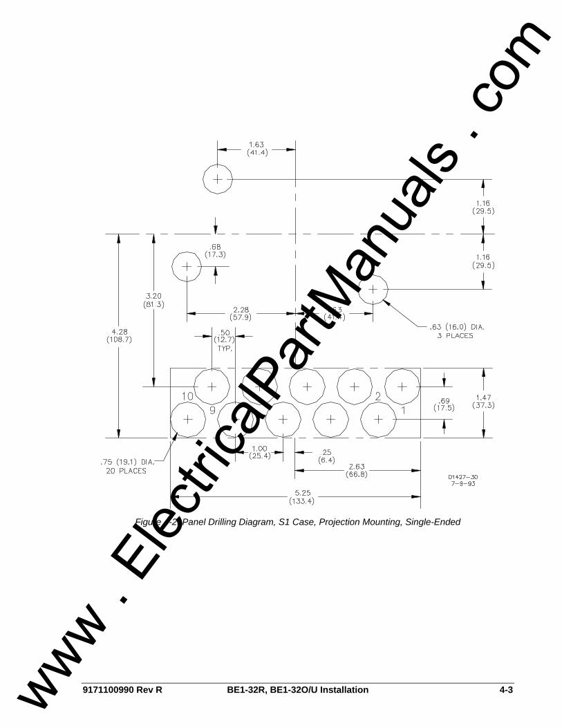
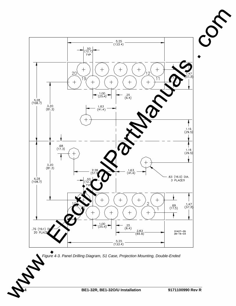
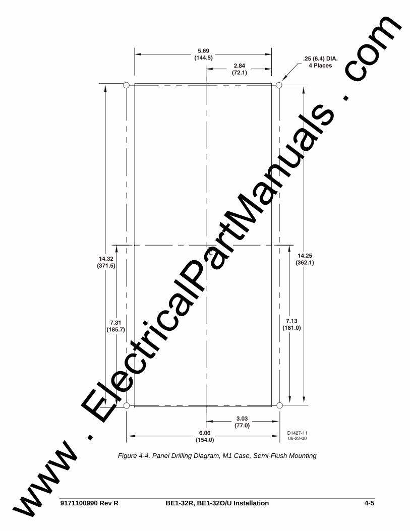
Panel Drilling Diagrams and Outline Drawings Panel drilling diagrams are provided in Figures 4-1 through 4-5. Outline drawings showing case dimensions and case cover dimensions are provided in Figures 4-6 through 4-15.
CAUTION When the connection plugs are removed, the relay is disconnected from the operating circuit and will not provide system protection. Always be sure that external operating (monitored) conditions are stable before removing a relay for inspection, test, or service.
NOTE Be sure that the relay is hard-wired to earth ground with no smaller than 12 AWG copper wire attached to the ground terminal on the rear of the unit case. When the relay is configured in a system with other devices, it is recommended to use a separate lead to the ground bus from each device.
www . El
ectric
alPar
tMan
uals
. com
4-2 BE1-32R, BE1-32O/U Installation 9171100990 Rev R
Figure 4-1. Panel Drilling Diagram, S1 Case, Semi-Flush Mounting
www . El
ectric
alPar
tMan
uals
. com
9171100990 Rev R BE1-32R, BE1-32O/U Installation 4-3
Figure 4-2. Panel Drilling Diagram, S1 Case, Projection Mounting, Single-Ended
www . El
ectric
alPar
tMan
uals
. com
4-4 BE1-32R, BE1-32O/U Installation 9171100990 Rev R
Figure 4-3. Panel Drilling Diagram, S1 Case, Projection Mounting, Double-Ended
www . El
ectric
alPar
tMan
uals
. com
9171100990 Rev R BE1-32R, BE1-32O/U Installation 4-5
Figure 4-4. Panel Drilling Diagram, M1 Case, Semi-Flush Mounting
www . El
ectric
alPar
tMan
uals
. com

4-6 BE1-32R, BE1-32O/U Installation 9171100990 Rev R
Figure 4-5. Panel Drilling Diagram, M1 Case, Projection Mounting
www . El
ectric
alPar
tMan
uals
. com
9171100990 Rev R BE1-32R, BE1-32O/U Installation 4-7
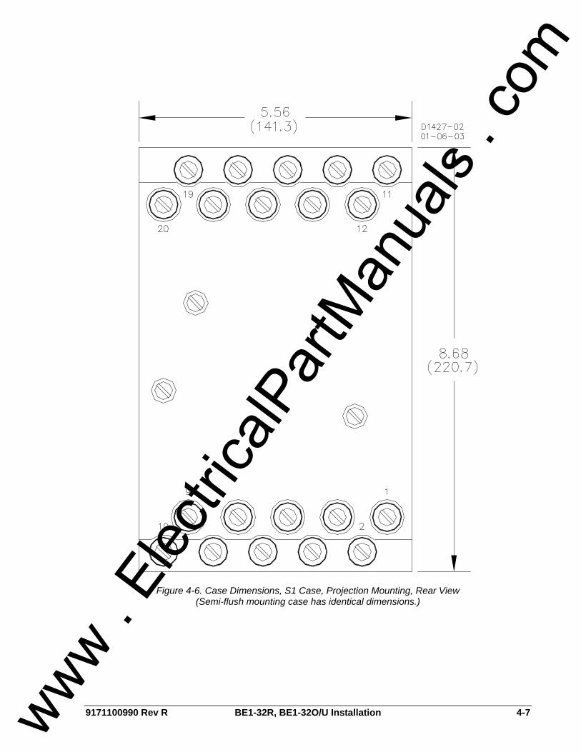
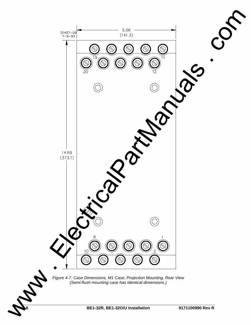
Figure 4-6. Case Dimensions, S1 Case, Projection Mounting, Rear View (Semi-flush mounting case has identical dimensions.)
www . El
ectric
alPar
tMan
uals
. com
4-8 BE1-32R, BE1-32O/U Installation 9171100990 Rev R
Figure 4-7. Case Dimensions, M1 Case, Projection Mounting, Rear View (Semi-flush mounting case has identical dimensions.)
www . El
ectric
alPar
tMan
uals
. com

9171100990 Rev R BE1-32R, BE1-32O/U Installation 4-9
D2856-2306-15-99
Figure 4-8. Case Dimensions, S1 Case, Semi-Flush Mounting, Single-Ended, Side View
www . El
ectric
alPar
tMan
uals
. com
4-10 BE1-32R, BE1-32O/U Installation 9171100990 Rev R
D2881-1504-17-00
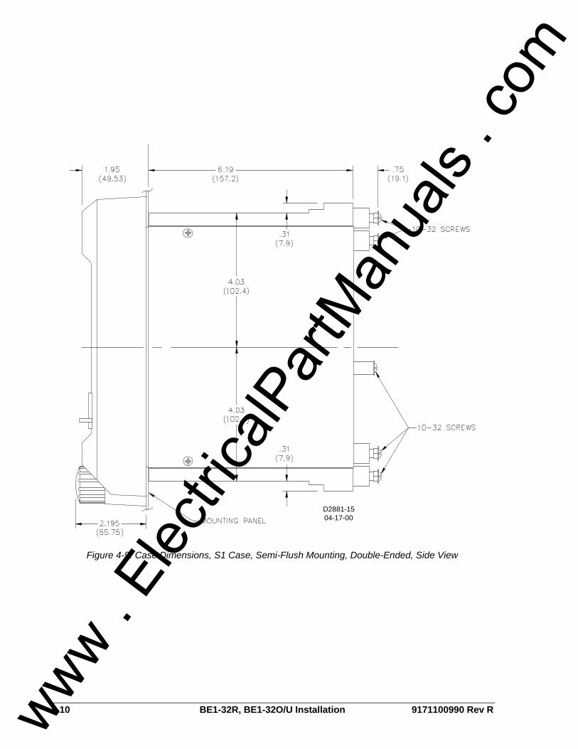
Figure 4-9. Case Dimensions, S1 Case, Semi-Flush Mounting, Double-Ended, Side View
www . El
ectric
alPar
tMan
uals
. com
9171100990 Rev R BE1-32R, BE1-32O/U Installation 4-11
P0002-1701-30-01
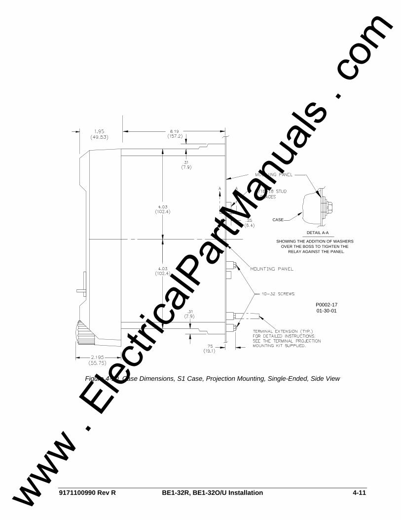
DETAIL A-A
SHOWING THE ADDITION OF WASHERSOVER THE BOSS TO TIGHTEN THE
RELAY AGAINST THE PANEL.
CASE
Figure 4-10. Case Dimensions, S1 Case, Projection Mounting, Single-Ended, Side View
www . El
ectric
alPar
tMan
uals
. com

4-12 BE1-32R, BE1-32O/U Installation 9171100990 Rev R
Figure 4-11. Case Dimensions, S1 Case, Projection Mounting, Double-Ended, Side View
www . El
ectric
alPar
tMan
uals
. com
9171100990 Rev R BE1-32R, BE1-32O/U Installation 4-13
P0002-1509-07-00
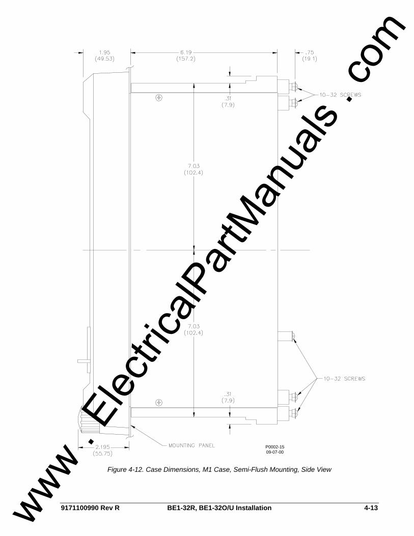
Figure 4-12. Case Dimensions, M1 Case, Semi-Flush Mounting, Side View
www . El
ectric
alPar
tMan
uals
. com
4-14 BE1-32R, BE1-32O/U Installation 9171100990 Rev R
P0002-1609-07-00
DETAIL A-A
SHOWING THE ADDITION OF WASHERSOVER THE BOSS TO TIGHTEN THE
RELAY AGAINST THE PANEL.
CASEPANEL
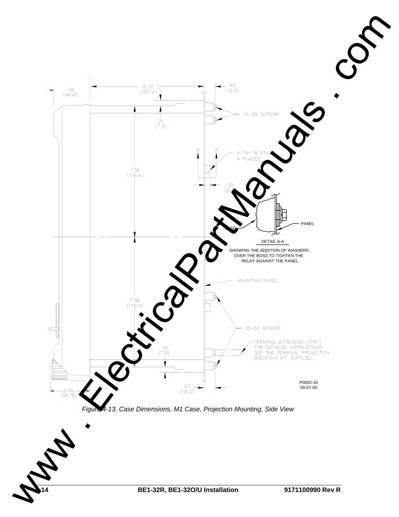
Figure 4-13. Case Dimensions, M1 Case, Projection Mounting, Side View
www . El
ectric
alPar
tMan
uals
. com
9171100990 Rev R BE1-32R, BE1-32O/U Installation 4-15
P0002-1201-31-01
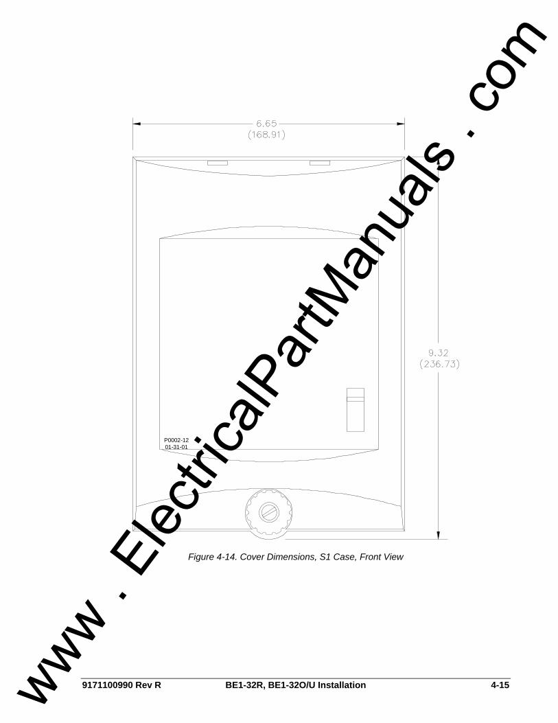
Figure 4-14. Cover Dimensions, S1 Case, Front View
www . El
ectric
alPar
tMan
uals
. com

4-16 BE1-32R, BE1-32O/U Installation 9171100990 Rev R
P0002-1408-10-01
Figure 4-15. Cover Dimensions, M1 Case, Front View www .
Elec
tricalP
artM
anua
ls . c
om
9171100990 Rev R BE1-32R, BE1-32O/U Installation 4-17
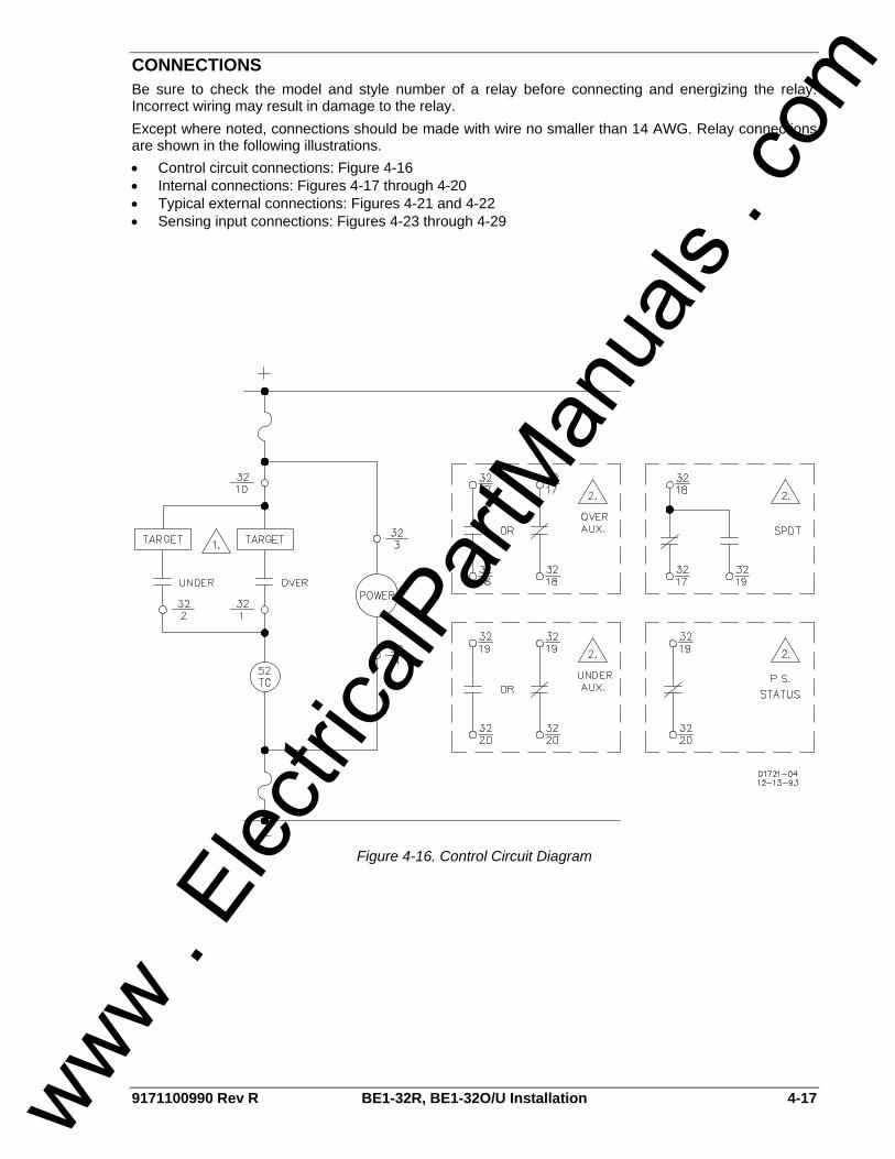
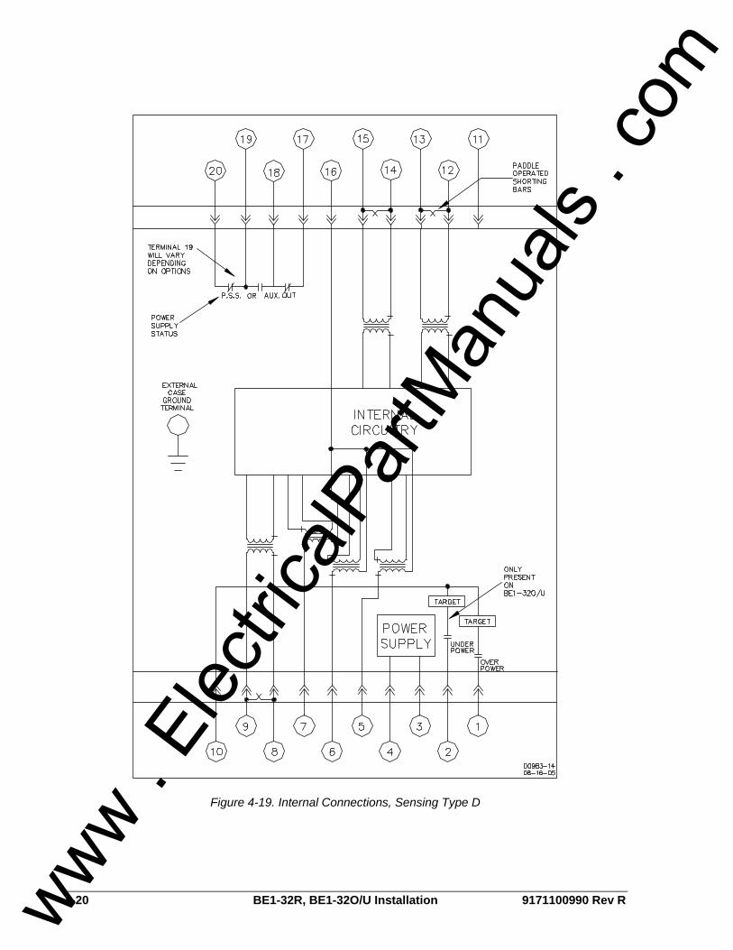
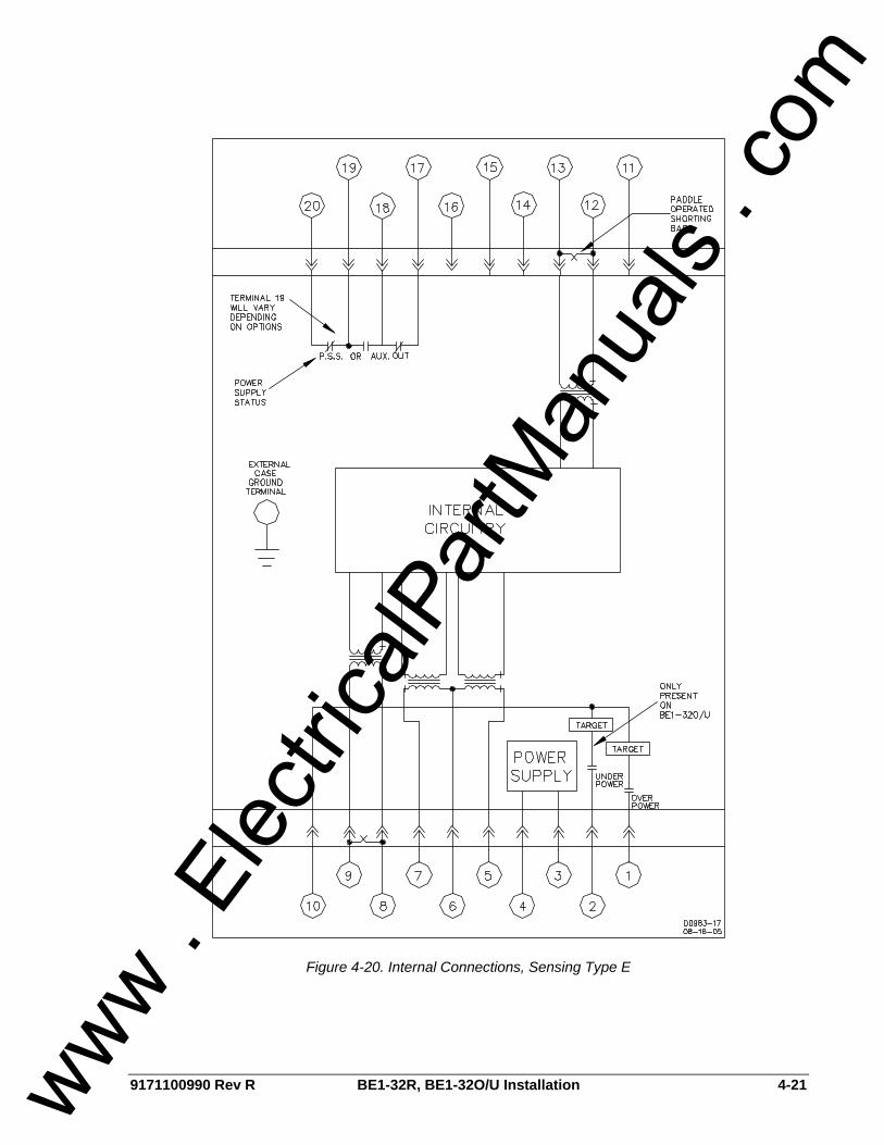
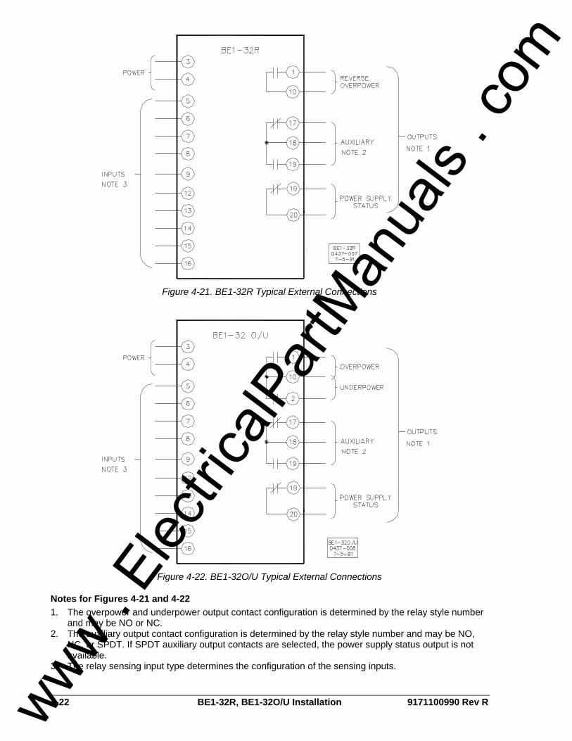
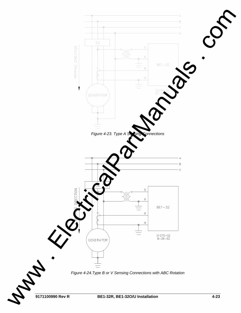
CONNECTIONS Be sure to check the model and style number of a relay before connecting and energizing the relay. Incorrect wiring may result in damage to the relay. Except where noted, connections should be made with wire no smaller than 14 AWG. Relay connections are shown in the following illustrations. • Control circuit connections: Figure 4-16 • Internal connections: Figures 4-17 through 4-20 • Typical external connections: Figures 4-21 and 4-22 • Sensing input connections: Figures 4-23 through 4-29
Figure 4-16. Control Circuit Diagram
www . El
ectric
alPar
tMan
uals
. com

4-18 BE1-32R, BE1-32O/U Installation 9171100990 Rev R
Figure 4-17. Internal Connections, Sensing Type A, B, or V
www . El
ectric
alPar
tMan
uals
. com
9171100990 Rev R BE1-32R, BE1-32O/U Installation 4-19
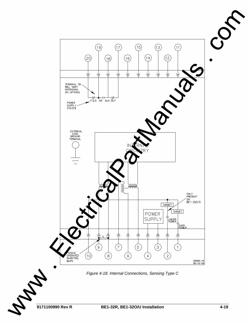
Figure 4-18. Internal Connections, Sensing Type C
www . El
ectric
alPar
tMan
uals
. com
4-20 BE1-32R, BE1-32O/U Installation 9171100990 Rev R
Figure 4-19. Internal Connections, Sensing Type D
www . El
ectric
alPar
tMan
uals
. com
9171100990 Rev R BE1-32R, BE1-32O/U Installation 4-21
Figure 4-20. Internal Connections, Sensing Type E
www . El
ectric
alPar
tMan
uals
. com
4-22 BE1-32R, BE1-32O/U Installation 9171100990 Rev R
Figure 4-21. BE1-32R Typical External Connections
Figure 4-22. BE1-32O/U Typical External Connections
Notes for Figures 4-21 and 4-22 1. The overpower and underpower output contact configuration is determined by the relay style number
and may be NO or NC. 2. The auxiliary output contact configuration is determined by the relay style number and may be NO,
NC, or SPDT. If SPDT auxiliary output contacts are selected, the power supply status output is not available.
3. The relay sensing input type determines the configuration of the sensing inputs.
www . El
ectric
alPar
tMan
uals
. com
9171100990 Rev R BE1-32R, BE1-32O/U Installation 4-23
Figure 4-23. Type A Sensing Connections
Figure 4-24.Type B or V Sensing Connections with ABC Rotation
www . El
ectric
alPar
tMan
uals
. com

4-24 BE1-32R, BE1-32O/U Installation 9171100990 Rev R
Figure 4-25. Type B or V Sensing Connections with ACB Rotation
Figure 4-26. Type C Sensing Connections
www . El
ectric
alPar
tMan
uals
. com
9171100990 Rev R BE1-32R, BE1-32O/U Installation 4-25
Figure 4-27. Type D Sensing Connections
www . El
ectric
alPar
tMan
uals
. com
4-26 BE1-32R, BE1-32O/U Installation 9171100990 Rev R
Figure 4-28. Type E Sensing Connections with ABC Rotation
www . El
ectric
alPar
tMan
uals
. com
9171100990 Rev R BE1-32R, BE1-32O/U Installation 4-27
Figure 4-29. Type E Sensing Connections with ACB Rotation
www . El
ectric
alPar
tMan
uals
. com

4-28 BE1-32R, BE1-32O/U Installation 9171100990 Rev R
MAINTENANCE BE1-32R and BE1-32O/U relays require no preventative maintenance other than testing performed according to scheduled practices.
Repair Repair of the draw-out assembly by replacement of individual circuit boards is not recommended. The printed circuit boards are not intended to be field serviceable. If a relay failure occurs in a critical application without sufficient redundancy, protection can be restored by inserting a spare relay in the mounted and wired case of the relay requiring service. The draw-out assembly requiring service can then be returned for service in the case from the spare relay. If a spare case is not available, care should be used when packing the draw-out assembly for shipment. Use anti-static packing material that prevents mechanical damage during transit. Before returning a relay for repair, contact the Basler Electric Technical Services Department at 618-654-2341 for a return authorization number.
Maintenance Accessories
Test Plug Test plugs (Basler P/N 10095) enable relay testing without removing the relay from the case. Test plugs are simply substituted for the connection plugs. This provides access to the external stud connections as well as the internal circuitry. Test plugs consist of black and red phenolic moldings with 20 electrically separated contact fingers connected to 10 coaxial binding posts. Fingers on the black side are connected to the inner binding posts (black thumbnuts) and tap into the relay internal circuitry. Fingers on the red side of the test plug are connected to the outer binding posts (red thumbnuts) and connect to the relay case terminals. When testing circuits connected to the bottom set of case terminals, the test plug is inserted with the numbers 1 through 10 facing up. Similarly, when using the test plug in the upper part of the relay, the test plug is inserted with the numbers 11 through 20 facing up. Due to the construction of the test plug, it is impossible to insert it with the wrong orientation.
www . El
ectric
alPar
tMan
uals
. com
9171100990 Rev R BE1-32R, BE1-32O/U Testing i
SECTION 5 • TESTING TABLE OF CONTENTS
SECTION 5 • TESTING ............................................................................................................................ 5-1
INTRODUCTION.................................................................................................................................... 5-1 TEST PROCEDURES ........................................................................................................................... 5-1
Connections........................................................................................................................................ 5-1 Overpower Pickup and Dropout (Unity Power Factor) ....................................................................... 5-1 Underpower Pickup and Dropout (Unity Power Factor) ..................................................................... 5-1 Instantaneous Time (Overpower)....................................................................................................... 5-2 Definite Time (Overpower) ................................................................................................................. 5-2 Definite Time (Underpower) ............................................................................................................... 5-2 Inverse Time (Overpower).................................................................................................................. 5-3
Figures Figure 5-1. Type A Sensing Test Connections.......................................................................................... 5-4 Figure 5-2. Type B or V Sensing Test Connections .................................................................................. 5-5 Figure 5-3. Type C Sensing Test Connections ......................................................................................... 5-6 Figure 5-4. Type D Sensing Test Connections ......................................................................................... 5-7 Figure 5-5. Type E Sensing Test Connections.......................................................................................... 5-8
www . El
ectric
alPar
tMan
uals
. com

ii BE1-32R, BE1-32O/U Testing 9171100990 Rev R
This page intentionally left blank.
www . El
ectric
alPar
tMan
uals
. com

9171100990 Rev R BE1-32R, BE1-32O/U Testing 5-1
SECTION 5 • TESTING INTRODUCTION The following procedures verify proper relay operation and calibration. Results obtained from these procedures may not fall within specified tolerances. When evaluating results, consider three prominent factors: • Test equipment accuracy • Testing method (e.g., timing start signal) • External test set components tolerance level
TEST PROCEDURES
Connections Relay test connections depend upon the relay sensing type. Connect the relay using the appropriate illustration as a reference. Type A sensing: Figure 5-1 Type B, V sensing: Figure 5-2 Type C sensing: Figure 5-3 Type D sensing: Figure 5-4 Type E sensing: Figure 5-5
Overpower Pickup and Dropout (Unity Power Factor) 1. Make the following relay front panel setting adjustments. Note that relays with inverse or
instantaneous timing options will not have an Overpower Time Delay Multiplier Switch.
Range Select Switch: LOW Overpower Tap Selector: B Overpower Time Delay Control: 00 (instantaneous) Overpower Time Delay Multiplier Switch: x0.1 Underpower Pickup Selector: FULLY CCW 2. Apply operating power to the relay at case terminals 3 and 4. 3. Apply nominal sensing input voltage to the appropriate case terminals. A single voltage source may
be connected to paralleled relay sensing voltage inputs to simulate a three-phase source. 4. Apply a current source to the relay current sensing inputs and increase the current level until the
Overpower Pickup Indicator just lights. The Overpower output contacts, auxiliary output contacts, and target indicators should operate. Verify that the wattmeter indicates a power reading that is within 2% of the Overpower Tap Selector
setting. The pickup setting for tap B, low range is listed on the front panel Tap Selection Chart. 5. Slowly reduce the applied current until the Overpower Pickup Indicator just turns off.
Verify that the wattmeter indicates a power reading that is within 98% of the pickup value established in step 4. Reset the target indicators.
6. Repeat steps 4 and 5 for Overpower Tap Selector settings of E and K.
Underpower Pickup and Dropout (Unity Power Factor) 1. Make the following relay front panel setting adjustments. Note that relays with inverse or
instantaneous timing options will not have an Overpower Time Delay Multiplier Switch. Underpower Time Delay Multiplier Switch: LOW
Underpower Pickup Selector: FULLY CW Underpower Time Delay Control: 00 (instantaneous) Overpower, Underpower Time Delay Multiplier Switch: x0.1 Overpower Tap Selector: B 2. Apply operating power to the relay at case terminals 3 and 4.
www . El
ectric
alPar
tMan
uals
. com

5-2 BE1-32R, BE1-32O/U Testing 9171100990 Rev R
3. Apply nominal sensing input voltage to the appropriate case terminals. A single voltage source may be connected to paralleled relay sensing voltage inputs to simulate a three-phase source.
4. Apply a current source to the relay current sensing inputs and increase the current level until it is greater than the underpower pickup point.
5. Slowly decrease the applied current until the Underpower Pickup Indicator just lights. The Underpower output contacts, auxiliary output contacts, and target indicators should operate. Verify that the wattmeter indicates a power reading that is within 2% or 0.1 W, whichever is greater, of 95% of the Overpower Tap Selector setting. The pickup setting for tap B, low range is listed on the front panel Tap Selection Chart.
6. Slowly increase the applied current until the Underpower Pickup Indicator just turns off. Verify that the wattmeter reading is within 105% of the underpower pickup value established in step 5.
Instantaneous Time (Overpower) 1. Connect the timer/counter so that timing begins when sensing current is applied, and ends when the
Overpower output energizes. 2. Select a mid-range pickup point and apply sensing voltage that is appropriate for the relay. 3. Apply a step change in current that will yield two times the selected overpower setting at unity power
factor. Measure the interval from current application to Overpower output activation. The measured time delay should be less than 80 ms at 60 Hz or less than 100 ms at 50 Hz.
Definite Time (Overpower) 1. Connect the timer/counter so that timing begins when sensing current is applied, and ends when the
Overpower output energizes. 2. Make the following front panel setting adjustments.
Range Select Switch: LOW Overpower Tap Selector: B Overpower Time Delay Control: 01 Overpower Time Delay Multiplier Switch: x0.1 Underpower Pickup Selector: FULLY CCW
3. Apply operating power to the relay at case terminals 3 and 4. 4. Apply nominal sensing input voltage to the appropriate case terminals. A single voltage source may
be connected to paralleled relay sensing voltage inputs to simulate a three-phase source. 5. Adjust (but do not apply) the current source to a level that is two times the tap value. Apply the
current and measure the interval from current application to Overpower output activation. The measured time delay should be 0.1 ±0.050 seconds.
6. Repeat step 5 for Overpower Time Delay Control settings of 50 and 99. For an Overpower Time Delay Control setting of 50, the measured time delay should be 5.0 ±0.25 seconds. For an Overpower Time Delay Control setting of 99, the measured time delay should be 9.9 ±0.50 seconds.
Definite Time (Underpower) 1. Connect the timer/counter so that timing begins when sensing current is removed, and ends when the
Underpower output energizes. 2. Make the following front panel setting adjustments.
Range Select Switch: LOW Underpower Pickup Selector: FULLY CW Underpower Time Delay Control: 01 Overpower, Underpower Time Delay Multiplier Switch: x0.1 Overpower Tap Selector: B
3. Apply operating power to the relay at case terminals 3 and 4.
www . El
ectric
alPar
tMan
uals
. com

9171100990 Rev R BE1-32R, BE1-32O/U Testing 5-3
4. Apply nominal sensing input voltage to the appropriate case terminals. A single voltage source may be connected to paralleled relay sensing voltage inputs to simulate a three-phase source.
5. Apply a current source to the relay current sensing inputs and increase the current level until it is greater than the underpower pickup point.
6. Remove the applied current so that the Underpower Pickup Indicator lights and record the interval from the removal of current until actuation of the Underpower output. The measured time delay should be 0.1 ±0.05 seconds.
7. Repeat steps 5 and 6 for an Underpower Time Delay Control setting of 05. The measured time delay should be 0.5 ±0.05 seconds.
8. Repeat steps 5 and 6 for an Underpower Time Delay Control setting of 50 and an Underpower Time Delay Multiplier Switch setting of x1.0. The measured time delay should be 50.0 ±2.50 seconds.
Inverse Time (Overpower) 1. Connect the timer/counter so that timing begins when sensing current is applied, and ends when the
Overpower output energizes. 2. Make the following front panel setting adjustments.
Range Select Switch: LOW Overpower Tap Selector: B Overpower Time Delay Control: 05 Overpower Time Delay Multiplier Switch: x0.1 Underpower Pickup Selector: FULLY CCW
3. Adjust (but do not apply) the current source to a level that is 4 times the tap value. Apply the current and measure the interval from current application to Overpower output activation. The measured time delay should be 0.460 ±0.050 seconds.
4. Adjust (but do not apply) the current source to a level that is 1.5 times the tap value. Apply the current and measure the interval from current application to Overpower output activation. The measured time delay should be 1.048 ±0.053 seconds.
5. Adjust (but do not apply) the current source to a level that is 8 times the tap value. Apply the current and measure the interval from current application to Overpower output activation. The measured time delay should be 0.282 ±0.050 seconds.
www . El
ectric
alPar
tMan
uals
. com
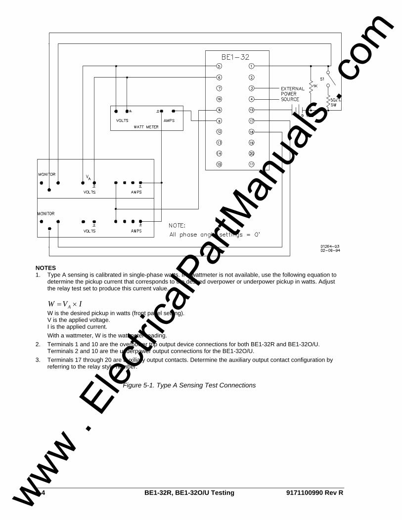
5-4 BE1-32R, BE1-32O/U Testing 9171100990 Rev R
NOTES 1. Type A sensing is calibrated in single-phase watts. If a wattmeter is not available, use the following equation to
determine the pickup current that corresponds to the desired overpower or underpower pickup in watts. Adjust the relay test set to produce this current value.
IVW A ×= W is the desired pickup in watts (front panel setting). V is the applied voltage. I is the applied current. With a wattmeter, W is the wattmeter reading.
2. Terminals 1 and 10 are the overpower trip output device connections for both BE1-32R and BE1-32O/U. Terminals 2 and 10 are the underpower output connections for the BE1-32O/U.
3. Terminals 17 through 20 are auxiliary output contacts. Determine the auxiliary output contact configuration by referring to the relay style number.
Figure 5-1. Type A Sensing Test Connections
www . El
ectric
alPar
tMan
uals
. com

9171100990 Rev R BE1-32R, BE1-32O/U Testing 5-5
NOTES 1. Types B and V (30° phase shift) sensing are calibrated in single-phase watts. If a wattmeter is not available, use
the following equation to determine the pickup current that corresponds to the desired overpower or underpower pickup in watts. Adjust the relay test set to produce this current value.
3IV
W A ×=
W is the desired pickup in watts. V is the applied voltage. I is the applied current. With a wattmeter, W is determined by the following equation.
5.1Reading WattmeterW =
2. Terminals 1 and 10 are the overpower trip output device connections for both BE1-32R and BE1-32O/U. Terminals 2 and 10 are the underpower output connections for the BE1-32O/U.
3. Terminals 17 through 20 are auxiliary output contacts. Determine the auxiliary output contact configuration by referring to the relay style number.
Figure 5-2. Type B or V Sensing Test Connections
www . El
ectric
alPar
tMan
uals
. com

5-6 BE1-32R, BE1-32O/U Testing 9171100990 Rev R
NOTES 1. Type C (Scott or T-connected) sensing is calibrated in three-phase watts. If a wattmeter is not available, us the
following equation to determine the pickup current that corresponds to the desired overpower or underpower pickup in watts. Adjust the relay test set to produce this current value.
IVW A ××= 3
W is the desired pickup in watts. V is the applied voltage. I is the applied current. With a wattmeter, W is determined by the following equation.
Reading WattmeterW ×= 2
2. Terminals 1 and 10 are the overpower trip output device connections for both BE1-32R and BE1-32O/U. Terminals 2 and 10 are the underpower output connections for the BE1-32O/U.
3. Terminals 17 through 20 are auxiliary output contacts. Determine the auxiliary output contact configuration by referring to the relay style number.
Figure 5-3. Type C Sensing Test Connections
www . El
ectric
alPar
tMan
uals
. com
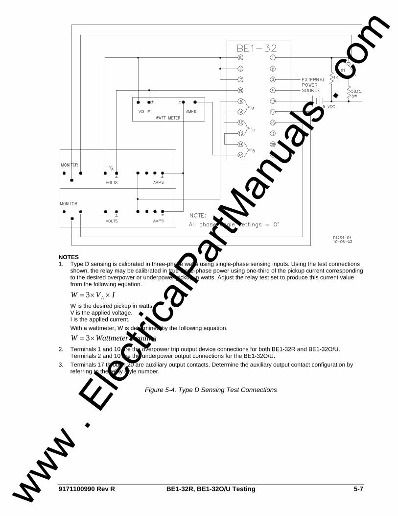
9171100990 Rev R BE1-32R, BE1-32O/U Testing 5-7
NOTES 1. Type D sensing is calibrated in three-phase watts using single-phase sensing inputs. Using the test connections
shown, the relay may be calibrated in true three-phase power using one-third of the pickup current corresponding to the desired overpower or underpower pickup in watts. Adjust the relay test set to produce this current value from the following equation.
IVW A ××= 3
W is the desired pickup in watts. V is the applied voltage. I is the applied current. With a wattmeter, W is determined by the following equation.
Reading WattmeterW ×= 3
2. Terminals 1 and 10 are the overpower trip output device connections for both BE1-32R and BE1-32O/U. Terminals 2 and 10 are the underpower output connections for the BE1-32O/U.
3. Terminals 17 through 20 are auxiliary output contacts. Determine the auxiliary output contact configuration by referring to the relay style number.
Figure 5-4. Type D Sensing Test Connections
www . El
ectric
alPar
tMan
uals
. com
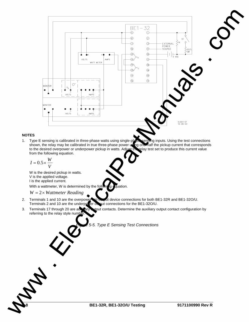
5-8 BE1-32R, BE1-32O/U Testing 9171100990 Rev R
NOTES 1. Type E sensing is calibrated in three-phase watts using single-phase sensing inputs. Using the test connections
shown, the relay may be calibrated in true three-phase power using one-half the pickup current that corresponds to the desired overpower or underpower pickup in watts. Adjust the relay test set to produce this current value from the following equation.
VWI ×= 5.0
W is the desired pickup in watts. V is the applied voltage. I is the applied current. With a wattmeter, W is determined by the following equation.
Reading WattmeterW ×= 2
2. Terminals 1 and 10 are the overpower trip output device connections for both BE1-32R and BE1-32O/U. Terminals 2 and 10 are the underpower output connections for the BE1-32O/U.
3. Terminals 17 through 20 are auxiliary output contacts. Determine the auxiliary output contact configuration by referring to the relay style number.
Figure 5-5. Type E Sensing Test Connections
www . El
ectric
alPar
tMan
uals
. com

ROUTE 143, BOX 269 HIGHLAND, IL 62249 USA
http://www.basler.com, [email protected] PHONE +1 618-654-2341 FAX +1 618-654-2351 www .
Elec
tricalP
artM
anua
ls . c
om