Embed Size (px)
Citation preview

CONCEPT OF OPERATIONS
NDOT Active Traffic Management System Las Vegas, Nevada Prepared for:
Prepared by:
Prepared In Accordance With:

NDOT Active Traffic Management (ATM) Concept of Operations
i
TABLE OF CONTENTS 1 Overview .......................................................................................................................... 1
1.1 Background ................................................................................................................................... 1 1.2 Purpose ......................................................................................................................................... 1 1.3 Scope ............................................................................................................................................. 2 1.4 Best Practice Examples ................................................................................................................. 3 1.5 Role within the Systems Engineering Process .............................................................................. 4 1.6 Goals and Objectives ..................................................................................................................... 5
2 Current Conditions ........................................................................................................... 7
2.1 Existing ITS Infrastructure ............................................................................................................. 7 2.2 FAST TMC ...................................................................................................................................... 8 2.3 Project Neon ................................................................................................................................. 9 2.4 Local Agencies ............................................................................................................................. 10 2.5 Stakeholder Roles and Responsibilities ...................................................................................... 10
3 NDOT ATM Applications ................................................................................................. 14
3.1 ATM Technologies ....................................................................................................................... 14 3.2 ATM Applications ........................................................................................................................ 16
4 Concepts of the Proposed System .................................................................................. 18
4.1 Overarching ATM Management Guidelines................................................................................ 18 4.2 Lane Management System Concept ........................................................................................... 19 4.3 Speed Harmonization (Regulatory Variable Speed Limit Concept) ............................................ 21 4.4 Queue Warning Concept ............................................................................................................. 23 4.5 Dynamic Lane Merging Concept (Junction Control) ................................................................... 25 4.6 Dynamic Ramp Metering Concept .............................................................................................. 26 4.7 Software Interface Concept ........................................................................................................ 27 4.8 Other Concept Considerations .................................................................................................... 28
5 Operational Scenarios .................................................................................................... 30
5.1 Context Diagram ......................................................................................................................... 30 5.2 Free Flow Scenario ...................................................................................................................... 32 5.3 Queue Warning Scenario ............................................................................................................ 32 5.4 Incident Scenario ........................................................................................................................ 33 5.5 Planned Closure Scenario ........................................................................................................... 37 5.6 Full Freeway Closure Scenario .................................................................................................... 39 5.7 Dynamic Merging Scenario ......................................................................................................... 41 5.8 Failure Conditions ....................................................................................................................... 43
6 Public Relations .............................................................................................................. 44
LIST OF TABLES Table 1-1: NDOT ATM Goals, Objectives and Measures of Effectiveness .................................................... 6 Table 2-1: Stakeholder Roles and Responsibilities ..................................................................................... 11

NDOT Active Traffic Management (ATM) Concept of Operations
ii
LIST OF FIGURES Figure 1-1: Causes of Congestion in the United States (Source: Congestion Mitigation FHWA) .................. 2 Figure 1-2: NDOT ATM Project Limits ........................................................................................................... 2 Figure 1-3: Examples of Active Traffic Management Operational Strategies ............................................... 3 Figure 1-4: The Systems Engineering “V” Diagram ....................................................................................... 4 Figure 2-1: Existing ITS Infrastructure on I-15 and US-95 ............................................................................. 7 Figure 2-2: Las Vegas FAST TMC ................................................................................................................... 8 Figure 2-3: Project Neon within NDOT ATM Limits .................................................................................... 10 Figure 3-1: Lane Control Signals and Information Display .......................................................................... 14 Figure 3-2: Lane Control Signals and Static Exit Signage ............................................................................ 14 Figure 4-1: Lane Management Displays ...................................................................................................... 20 Figure 4-2: HOV Restrictions Displays ......................................................................................................... 20 Figure 4-3: Speed Limit Displays ................................................................................................................. 22 Figure 4-4: Information Display Message Example to Support Speed Harmonization Lane Display ......... 22 Figure 4-5: Queue Warning Caution Lane Display ...................................................................................... 24 Figure 4-6: Information Display Message Example to Support Queue Warning Lane Display ................... 24 Figure 4-7: Information Display Message Example to Support Dynamic Merge System ........................... 26 Figure 5-1: NDOT ATM System Operation Context Diagram ...................................................................... 30 Figure 5-2: Free Flow Scenario .................................................................................................................... 32 Figure 5-3: Queue Warning Scenario .......................................................................................................... 33 Figure 5-4: Incident with Congestion Scenario ........................................................................................... 35 Figure 5-5: Incident without Congestion Scenario ..................................................................................... 36 Figure 5-6: Planned Closure Scenario ......................................................................................................... 38 Figure 5-7: Full Freeway Closure Scenario .................................................................................................. 40 Figure 5-8: Dynamic Merging Scenario ....................................................................................................... 42
REVISION HISTORY
Filename Version Date Author/QC Comment NDOT ATM Preliminary ConOps - DRAFT.docx
1.0 05/30/2014 DH / IZ / PP Draft Preliminary ConOps submitted to NDOT
NDOT ATM Preliminary ConOps – 6-12-2014.docx
1.1 06/12/2014 DH / IZ / PP Addresses comments from client and stakeholders
NDOT ATM Preliminary ConOps – 6-23-2014.docx
1.2 06/23/2014 DH / IZ / PP Addressed comments from client
NDOT ATM Preliminary ConOps – 7-2-2014.docx
1.3 07/02/2014 DH / IZ / PP Addressed comments from client – Final Preliminary ConOps submitted to NDOT
NDOT ATM Updated Draft ConOps – 10-6-2014.docx
1.4 10/06/2014 DH / IZ / PP Addressed updates with Design-Build process and refined scenarios
NDOT ATM ConOps – 10-14-2014.docx
1.5 10/14/2014 DH / IZ / PP Addressed input from client and stakeholders
NDOT ATM ConOps – 12-16-2014.docx
1.6 12/16/2014 DH / IZ / PP Addressed input from client and stakeholders regarding VSL

NDOT Active Traffic Management (ATM) Concept of Operations
NDOT ATM Concept of Operations December 2014 1 of 44
1 Overview
1.1 Background
The Active Traffic Management (ATM) definition from the Federal Highway Administration (FHWA) is the following:
“The ability to dynamically manage recurrent and non-recurrent congestion based on prevailing and predicted traffic conditions. Focusing on trip reliability, it maximizes the effectiveness and efficiency of the facility. It increases throughput and safety through the use of integrated systems with new technology, including the automation of dynamic deployment to optimize performance quickly and without delay that occurs when operators must deploy operational strategies manually. ATM approaches focus on influencing travel behavior with respect to lane/facility choices and operations. ATM strategies can be deployed singularly to address a specific need such as the utilizing adaptive ramp metering to control traffic flow or can be combined to meet system-wide needs of congestion management, traveler information, and safety resulting in synergistic performance gains.”
Project Neon is anticipated to begin construction toward the end of 2015 and it was determined that it was appropriate timing to introduce ATM technologies and applications through that project. ATM could support construction activities during Project Neon implementation as well as support congestion management along the most important stretch of I-15 through the heart of Las Vegas beyond the completion of Project Neon.
ATM Meeting was held on April 15, 2014 which described an overview of ATM concepts, best practice examples of ATM deployment, review of the FHWA ATDM Program, best practice measures of effectiveness, and the internal agency and external traveler outreach needs that will be required prior to ATM implementation to maximize effectiveness of ATM applications. An ATM Concept of Operations (ConOps) Workshop was held on May 15, 2014 to discuss goals and objectives of ATM, roles and responsibilities, and operational scenarios to be developed in this ConOps.
1.2 Purpose
Active traffic management is the ability to dynamically manage recurrent and non-recurrent congestion based on prevailing traffic conditions. The Nevada Department of Transportation (NDOT) has identified the need and also the opportunity to introduce its first ATM application in the state. ATM applications are focused on congestion management. The Las Vegas metropolitan area is already managed well through a network of Intelligent Transportation System (ITS) technologies on the freeways and on the arterials through a central management system.
Congestion management is a primary strategy that public agencies use to operate their facilities in this environment. Figure 1.1 illustrates a variety of factors, both recurring and nonrecurring, cause congestion for American travelers.

NDOT Active Traffic Management (ATM) Concept of Operations
NDOT ATM Concept of Operations December 2014 2 of 44
Figure 1-2: NDOT ATM Project Limits
Figure 1-1: Causes of Congestion in the United States (Source: Congestion Mitigation FHWA)
Agencies undertake freeway management and traffic operations through policies, strategies, and actions to enhance mobility and to combat recurring congestion in the freeway environment. Recurring congestion accounts for about 45 percent of all congestion in the United States. Nonrecurring congestion accounts for 55 percent of all congestion in the United States. These strategies include roadway improvements such as widening and bottleneck removal, operational improvements, ramp management and control, and managed lanes. Mitigation techniques for nonrecurring congestion include management of incidents, work zones, road weather, and planned special events. All of these strategies center on the theme of getting more out of facilities already in place.
NDOT ATM technologies and applications have been chosen carefully in order to combat both recurrent and non-recurrent congestion causes through the primary freeway serving the metropolitan area for commuters, visitors, long-haul truckers, and local traffic.
1.3 Scope
This document describes the ConOps for the implementation of ATM strategies along Interstate 15 (I-15) north from 215 to United States Numbered Route (US-95) and along US-95 west to Valley View Boulevard. Project limits for NDOT ATM technologies are shown in Figure 1-2 represented by the purple line. The system will dynamically manage and control traffic based on prevailing conditions to improve safety, reduce congestion, and support environmental sustainability.
ATM encompasses a variety of applications or strategies which range in complexity and functionality and can be used in concert with other applications such as adaptive ramp metering to provide spot improvements as well as overall corridor benefits. The system will use a variety of sensors, as well as human operators at the Freeway and Arterial System

NDOT Active Traffic Management (ATM) Concept of Operations
NDOT ATM Concept of Operations December 2014 3 of 44
of Transportation (FAST) Traffic Management Center (TMC) monitoring closed-circuit television (CCTV) cameras, to collect traffic data which will be processed and used to actuate various roadside systems such as lane control signals in near real-time to dynamically manage traffic based on prevailing conditions.
At the highest level, ATM can be defined as dynamically managing and controlling traffic based on prevailing conditions in order to improve safety and reduce congestion. These techniques target collisions that result from both recurrent and non-recurrent congestion. ATM is a tool that can improve safety and throughput and may be used as an interim strategy to enhance the efficiency of corridors that may ultimately receive major capital investments.
The goals for this NDOT initiative in Las Vegas are to improve traffic flow and safety through the use of dynamic lane management, queue warning, and speed harmonization (variable speed limits). Within the corridor, NDOT plans to consider the use of strategies to improve merge control near the on-ramps to I-15 and US-95 as well as near the freeway-to-freeway interchange and to improve operation of existing metered entrance ramps using adaptive and dynamic control strategies.
1.4 Best Practice Examples
ATM has been highly successful in Europe, notably in the United Kingdom, Netherlands and Germany. ATM improved both traffic safety and traffic flow by dynamically managing speeds and lane use based on prevailing traffic conditions and knowledge of downstream traffic blockages. Examples of ATM operating strategies are shown in Figure 1-3.
Figure 1-3: Examples of Active Traffic Management Operational Strategies
Best practices that were referenced in order to support the development of the Conops included:
NDOT Active Traffic Management (ATM) Concept of Operations
NDOT ATM Concept of Operations December 2014 4 of 44
Virginia Interstate-66 Active Traffic Management System – 2011: http://www.vdot.virginia.gov/projects/northernvirginia/i-66_atms.asp
Washington Active Traffic Management Concept of Operations – 2008: http://www.wsdot.wa.gov/NR/rdonlyres/73AC9A17-6178-4271-B3A9-91911BD1C8C6/0/FinalATMConceptofOperations.pdf
Minnesota Active Traffic Management “Smart Lanes” Concept of Operations
The following are references that were used to support the development of the ConOps:
Active Traffic Management: The Next Step in Congestion Management – FHWA 2007: http://international.fhwa.dot.gov/pubs/pl07012/
MUTCD Experimental Use Request for Active Traffic Management Signing: http://mutcd.fhwa.dot.gov/documents/pdf/2_09_4_ex_inc1.pdf
Integrating Active Traffic and Travel Demand Management: A Holistic Approach to Congestion Management – FHWA 2011: http://international.fhwa.dot.gov/pubs/pl11011/pl11011.pdf
Synthesis of Active Traffic Management Experiences in Europe and the United States – FHWA 2010: http://www.ops.fhwa.dot.gov/publications/fhwahop10031/sec4.htm
1.5 Role within the Systems Engineering Process
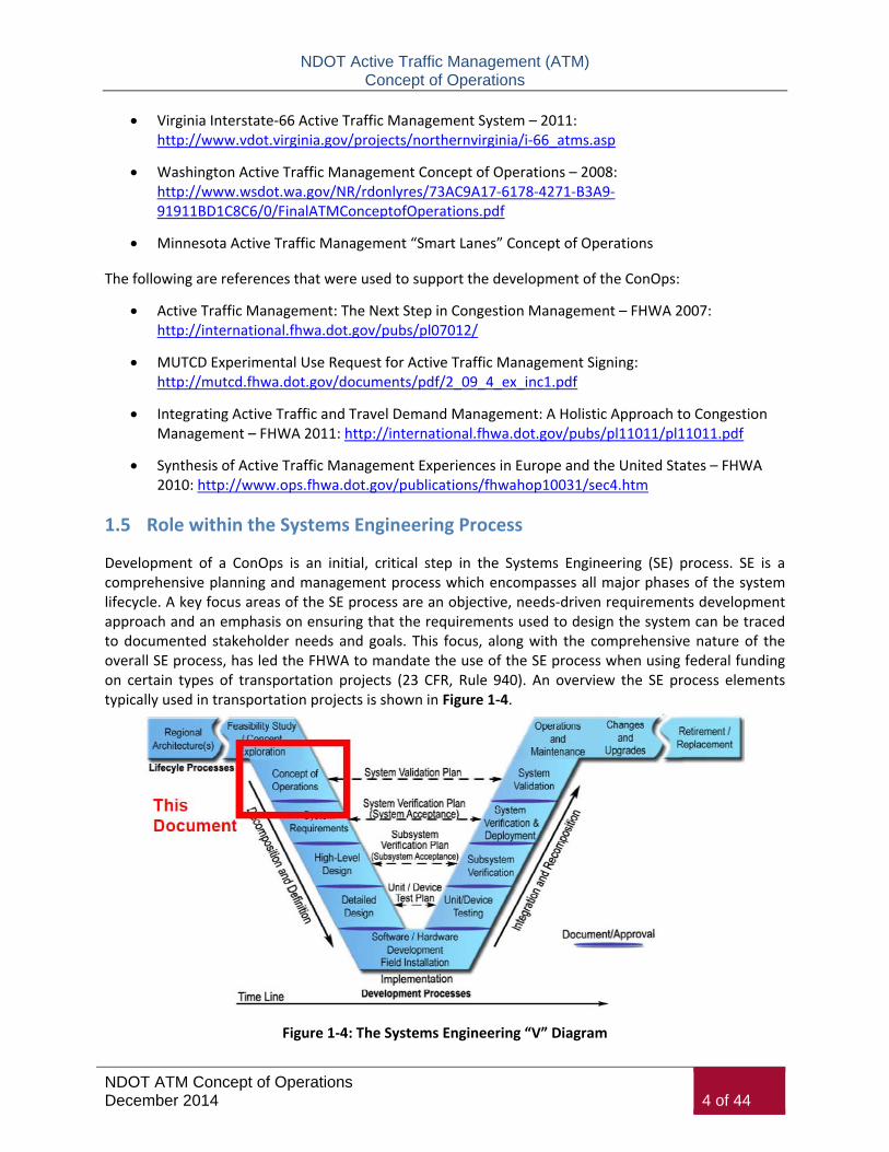
Development of a ConOps is an initial, critical step in the Systems Engineering (SE) process. SE is a comprehensive planning and management process which encompasses all major phases of the system lifecycle. A key focus areas of the SE process are an objective, needs-driven requirements development approach and an emphasis on ensuring that the requirements used to design the system can be traced to documented stakeholder needs and goals. This focus, along with the comprehensive nature of the overall SE process, has led the FHWA to mandate the use of the SE process when using federal funding on certain types of transportation projects (23 CFR, Rule 940). An overview the SE process elements typically used in transportation projects is shown in Figure 1-4.
Figure 1-4: The Systems Engineering “V” Diagram

NDOT Active Traffic Management (ATM) Concept of Operations
NDOT ATM Concept of Operations December 2014 5 of 44
This ConOps will be built upon in additional detail during the ATM software development in order to serve as the basis of the software functional requirements. In order for Federal funding to be authorized for the financing of major projects, the project must demonstrate to FHWA that it has been carefully planned out. Project requirements include the development of a Project Management Plan (PMP) and a Systems Engineering Management Plan (SEMP).
The PMP maps out the roles and responsibilities of the relevant parties in the management of the project through the planning, design, and implementation phases.
The SEMP demonstrates that systems engineering analysis has been done to outline practices that must be included in order to most effectively implement the project.
Both the PMP and the SEMP for this ATM project have been developed in order to meet FHWA requirements for applying Federal funding assistance in implementing the project.
1.6 Goals and Objectives
The NDOT ATM goals and objectives were formulated with a view to address the current and near term operational conditions, deficiencies, and needs. They also provide the framework for defining the ATM concepts and strategies.
Improvements as part of Project Neon are focused on capturing mobility, environment, and economic benefits that address goals focused in those areas. ATM is a management component of the freeway system that will likely experience similar benefits, although initially the focus is on two main factors in being:
1. Improving Safety 2. Providing Reliable Travel Conditions
Focusing the ATM on two goals rather than a myriad of potential goals allows NDOT to prioritize the measures of effectiveness that are well understood by the traveling public and by decision makers.
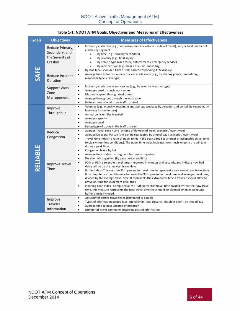
The following Table 1-1 identifies the two categories of goals and their associated objectives as well as potential measures of effectiveness that could be applied in order to define the performance and identify the success of achieving the goals.
It will be important for NDOT to define the specific performance metrics that will be used and potentially incorporated into the FAST Dashboard and the State’s 511 system. Metrics will require specific reporting requirements of the ATM System such as for law enforcement and operations purposes.
NDOT Active Traffic Management (ATM) Concept of Operations
NDOT ATM Concept of Operations December 2014 6 of 44
Table 1-1: NDOT ATM Goals, Objectives and Measures of Effectiveness
Goals Objectives Measures of Effectiveness SA
FE
Reduce Primary, Secondary, and the Severity of Crashes
Incident / crash rate (e.g., per person-hours or vehicle – miles of travel), and/or total number of crashes by segment
By type (e.g., primary/secondary) By severity (e.g., fatal, injury) By vehicle type (car / truck, enforcement / emergency service) By weather type (e.g., clear / dry, rain, snow, fog)
By lane type (shoulder, HOV / HOT) and corresponding ATM displays
Reduce Incident Duration
Average time to for responders to clear crash scene (e.g., by starting points, time-of-day, responder type, crash type)
Support Work Zone Management
Incident / crash rate in work zones (e.g., by severity, weather type) Average speed through work zones Maximum speed through work zones Average throughput through the work zone Reduced cost of work zone traffic control
RELI
ABL
E
Improve Throughput
Volumes (e.g., monthly, maximum and average weekday by direction and period, by segment, by lane type / shoulder use)
Annual vehicle-miles traveled Average capacity Average speed Percentage of trucks in the traffic stream
Reduce Congestion
Average Travel Time / Link (by time of day/day of week, scenario / event type) Average Delay per Person (this can be segregated by time of day / scenario / event type) Travel Time Index – a ratio of travel times in the peak period to a target or acceptable travel time
(typically free-flow conditions). The travel time index indicates how much longer a trip will take during a peak time.
Congestion levels by link Average time of day that segment becomes congested Duration of congestion (by peak period and link)
Improve Travel Time
90th or 95th percentile travel times - reported in minutes and seconds, and indicate how bad delay will be on the heaviest travel days
Buffer Index - This uses the 95th percentile travel time to represent a near-worst case travel time. It is computed as the difference between the 95th percentile travel time and average travel time, divided by the average travel time. It represents the extra buffer time a traveler should allow to arrive on-time for 95 percent of all trips
Planning Time Index - Computed as the 95th percentile travel time divided by the free-flow travel time, this measure represents the total travel time that should be planned when an adequate buffer time is included.
Improve Traveler Information
Accuracy of posted travel times (compared to actual) Types of information posted (e.g., speed limits, lane closures, shoulder open), by time of day Average time to post updated information Number of driver comments regarding posted information

NDOT Active Traffic Management (ATM) Concept of Operations
NDOT ATM Concept of Operations December 2014 7 of 44
2 Current Conditions
2.1 Existing ITS Infrastructure
The new NDOT ATM system will work within the environment of the existing freeway management system. Existing freeway management components include:
Closed circuit television (CCTV) cameras
Ramp metering
Dynamic message signs
Communication systems
Traffic detectors
NDOT owns the ITS technology deployed on the freeway and Regional Transportation Commission (RTC) FAST operates, manages, and maintains the system from the FAST TMC along with the arterial network infrastructure as an integrated regional system. The existing ITS infrastructure along the I-15 and US-95 corridors where ATM technologies are being proposed is shown in Figure 2-1.
Figure 2-1: Existing ITS Infrastructure on I-15 and US-95
The ATM techniques discussed in this document are consistent with the NDOT and FAST traffic management philosophy. They provide NDOT and FAST with another set of tools to help actively manage traffic conditions. The hardware required for lane management system and variable speed limits fits in well within the existing ITS infrastructure. There is existing fiber optic communication cable through the ATM proposed corridor to connect to controller equipment that will be provided on the roadside for ATM technologies.

NDOT Active Traffic Management (ATM) Concept of Operations
NDOT ATM Concept of Operations December 2014 8 of 44
Current traffic management systems require detectors and the same technology can be used for the variable speed limit detectors. In most locations, existing detector stations can be used to provide the data needed for the queue warning, dynamic ramp metering, and variable speed limit system.
Cameras will allow the operators to see all of the lane control and dynamic message signs. The dynamic message signs used to support these techniques are similar to signs used elsewhere by NDOT and FAST. New signs will be using NTCIP communication standards. NDOT manages and maintains its own ITS central software. The existing FAST CSS software already communicates with NTCIP signs; therefore the ATM CSS software update to integrate ATM application management makes integration much easier than if NDOT used only proprietary communication protocols.
NDOT currently orchestrates an incident management program with incident response patrols. ATM techniques such as queue warning would work to complement the existing ramp metering system when addressing mainline congestion.
2.2 FAST TMC
The Freeway and Arterial System of Transportation (FAST) TMC is an integrated and collocated center between NDOT, Regional Transportation Commission of Southern Nevada (RTC), and NHP. Transportation strategies for the FAST TMC to implement, operate, and maintain are discussed during the Operations Management Committee (OMC) comprised of the RTC, Clark County, NDOT and the cities of Henderson, Las Vegas and North Las Vegas. FAST is a multi-jurisdictional integrated traffic management system that streamlines the efficiency of metropolitan area traffic operations. A photo of the FAST TMC is provided to the right in Figure 2-2.
FAST has a comprehensive ITS infrastructure program having deployed closed-circuit television (CCTV) cameras; dynamic message signs (DMS); non-intrusive performance monitoring devices that detect vehicle volume, speed and occupancy; ramp meters at freeway entrances; and an upgraded distributed traffic signal system on a number of corridors. FAST has created a regional signal synchronization network that currently has approximately 1,200 traffic signals, with an average of 3-5 new signals being added to the network every month. FAST has established communications and implemented signal coordination plans at approximately 1,000 of those signals as FAST works with area agencies to install fiber optics and new or upgraded signal controllers across the Valley. The FAST signal synchronization network is designed to monitor and control the traffic signals, with the local agencies handling any required maintenance of the signals. Freeway ramp meters have been deployed in the Las Vegas Valley on portions of US-95, I-515, and I-15 through a successful joint project between RTC and NDOT. FAST controls the ramp meters and consistently monitors and adjusts the ramp meter timing, if needed, to
Figure 2-2: Las Vegas FAST TMC

NDOT Active Traffic Management (ATM) Concept of Operations
NDOT ATM Concept of Operations December 2014 9 of 44
ensure that the ramp meters do not create congestion on adjacent surface streets. NDOT operates and manages a Freeway Service Patrol and Incident Response Vehicle program, which provides free roadside assistance on freeways to disabled vehicles and after incidents.
The core purpose of FAST is to operate and maintain a diverse array of ITS devices that have been deployed with the aim of moving vehicular traffic safely, efficiently and effectively through both the arterial street system and the regional freeway networks in the region. DMS provide drivers with information about roadway conditions and travel times. Many closed-circuit television cameras are linked into RTC’s website so that travelers may view freeway conditions and some major arterial conditions in real time.
The FAST Dashboard (Performance Monitoring and Measurement System) is a software program that provides a web-based user interface to enable the public to pull and depict real-time and historical freeway network monitoring and performance information in a wide variety of user-selectable and user-customizable displays. FAST collects lane-by-lane data on the freeways and uses this information along with other raw data automatically gathered by the ITS that NDOT has implemented on its freeway network in southern Nevada, plus incident-specific data logged by FAST’s technicians. By integrating these data, the FAST Dashboard develops maps, charts and graphs showing trends and ‘report cards’ on freeway performance, and also enables the user to quantitatively characterize the discrete traffic flows.
The measures of effectiveness provided in Table 1-1 provide guidance on the types of metrics that could be incorporated into the FAST TMC performance dashboard or NDOT performance reporting. Measures in this document are provided as examples only and ultimate measures should account for the ability to collect the specified data to calculate the measure. Before and after data shall be collected as ATM applications are used as well in order to show benefits of ATM implementation and use.
2.3 Project Neon
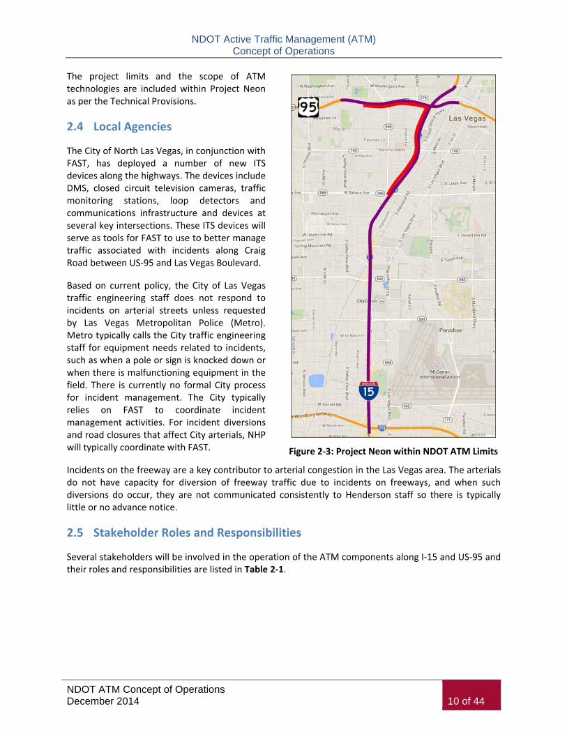
Project Neon is an infrastructure improvement project in the downtown area between Tropicana Avenue and US-93/US-95 that includes construction of northbound and southbound HOV lanes on I-15, reconstruction of existing traffic interchanges, and local access improvements such as construction of additional freeway ramps, a new arterial connection over I-15, and a new bridge over the Union Pacific Railroad. NDOT is currently reviewing the conceptual plans for Project Neon in an attempt to break the project into smaller phases. The first phase is anticipated to include a direct connection from the US-95 High-Occupancy Vehicle (HOV) lanes to the I-15 express lanes. Figure 2-3 on the next page provides an overview of the scope of Project Neon limits (shown as red line) within the entire NDOT ATM deployment project limits (shown as purple line).
NDOT Active Traffic Management (ATM) Concept of Operations
NDOT ATM Concept of Operations December 2014 10 of 44
Figure 2-3: Project Neon within NDOT ATM Limits
The project limits and the scope of ATM technologies are included within Project Neon as per the Technical Provisions.
2.4 Local Agencies
The City of North Las Vegas, in conjunction with FAST, has deployed a number of new ITS devices along the highways. The devices include DMS, closed circuit television cameras, traffic monitoring stations, loop detectors and communications infrastructure and devices at several key intersections. These ITS devices will serve as tools for FAST to use to better manage traffic associated with incidents along Craig Road between US-95 and Las Vegas Boulevard.
Based on current policy, the City of Las Vegas traffic engineering staff does not respond to incidents on arterial streets unless requested by Las Vegas Metropolitan Police (Metro). Metro typically calls the City traffic engineering staff for equipment needs related to incidents, such as when a pole or sign is knocked down or when there is malfunctioning equipment in the field. There is currently no formal City process for incident management. The City typically relies on FAST to coordinate incident management activities. For incident diversions and road closures that affect City arterials, NHP will typically coordinate with FAST.
Incidents on the freeway are a key contributor to arterial congestion in the Las Vegas area. The arterials do not have capacity for diversion of freeway traffic due to incidents on freeways, and when such diversions do occur, they are not communicated consistently to Henderson staff so there is typically little or no advance notice.
2.5 Stakeholder Roles and Responsibilities
Several stakeholders will be involved in the operation of the ATM components along I-15 and US-95 and their roles and responsibilities are listed in Table 2-1.

NDOT Active Traffic Management (ATM) Concept of Operations
NDOT ATM Concept of Operations December 2014 11 of 44
Table 2-1: Stakeholder Roles and Responsibilities
Stakeholder Operations Roles and Responsibilities Management Roles and Responsibilities
FAST TMC
Operate and manage the traffic management system ATM components
Monitor corridor for congestion and incidents
Activate signals for lane closures during congestion or incidents and as requested by NHP
Receive regular system status reports Provide traffic video to general public and
the media Develop performance measures
Integrate and operate the ATM system management
Develop and refine ATM operational strategies with participation from partner agencies
Management of fiber Maintenance of ITS technologies on freeway
system Establish automated alerts to partner agencies
for lane closures that have been activated on an ATM gantry
Traffic management planning during construction
Operate and maintain performance measures for ATM system
NDOT District 1
Provides dispatch support for the Freeway Service Patrol and Incident Response Vehicles
Manage regional traffic control efforts and assist in coordinating traffic across boundaries
Post work zone information on NDOT web page in advance of scheduled construction phasing
Dedicated dispatch at the FAST TMC Partner in developing FAST ATM operational
procedures Interface with entities seeking information
about Project Neon and ATM Maintains portable HAR stations for special
event use Update traveler information for dissemination
through 511 system
NDOT Headquarters
Manage Freeway Service Patrol and Incident Response Vehicles for freeway corridors
Customer service Statewide 511 Nevada program Safety management Develop and manage operational policy for
FAST TMC Update the JOPS for the ATMS System Update FAST Agreement for TIM Coalition
Implement and manage software for ATM system management
Funding support for FAST TMC operations and management of ATM system
Review performance measures Implement safety mitigation Public relations Technical support Provides Freeway Service Patrol (FSP) for
corridors Update HAZMAT agreement to include new
provisions related to project limits (NDOT Traffic Ops)
Statewide guidelines on Active Traffic Management
Statewide regulations on use of lane closures and ramp meters
Statewide data sharing program Statewide DMS guidelines and policies

NDOT Active Traffic Management (ATM) Concept of Operations
NDOT ATM Concept of Operations December 2014 12 of 44
Table 2-1: Stakeholder Roles and Responsibilities (continued)
Stakeholder Operations Roles and Responsibilities Management Roles and Responsibilities
Nevada Highway Patrol
Receive alerts for lane closures that have been activated on an ATM gantry
Receive alerts from NDOT and FAST TMC regarding maintenance activities that may impact incident management and response
Request lane closures from FAST TMC due to incidents or blockages in general purpose traffic lanes
Enforcement of lane closure regulations (e.g., tickets to drivers traveling in restricted lanes when lane use is not permitted), along with other traffic laws
Incident scene management if Fire/Rescue services not present
Enforcement of regulatory displays at ramp meter signals
Notify Clark County Traffic Management in the event of a fatality on the County 215 Beltway
Special authority for trucks as motor carrier enforcement
Partner in developing FAST ATM operational procedures
Participate in receiving and sharing education on ATM system management and operations
Develop client view of incidents through TMDD
Clark County
Receive alerts for lane closures that have been activated on an ATM gantry
Receive alerts from NDOT and FAST TMC regarding maintenance activities that may impact incident management and response
Investigates all fatal crashes in the County
Partner in developing FAST ATM operational procedures, particularly for coroner involvement in fatal incidents
Participate in receiving and sharing education on ATM system management and operations
Local Cities – Transportation
Receive alerts for lane closures that have been activated on an ATM gantry
Coordination of operations during construction after-hours
Support function to FAST/RTC with respect to signal coordination
Partner in developing FAST ATM operational procedures
Participate in receiving and sharing education on ATM system management and operations
Local Cities – Public Safety
Management of incident scenes in partnership with NHP if Fire/Rescue services not present
Incident scene management Provide emergency care and rescue services
at incident sites Provide fire containment and initial
HAZMAT response and containment on their facility jurisdiction
Provide emergency medical care Transport injured from incident scene to
hospital
Partner with NHP in developing operational procedures and enforcing lane closures, ramp meter displays, and other traffic laws
Participate in receiving and sharing education on ATM system management and operations

NDOT Active Traffic Management (ATM) Concept of Operations
NDOT ATM Concept of Operations December 2014 13 of 44
Table 2-1: Stakeholder Roles and Responsibilities (continued)
Stakeholder Operations Roles and Responsibilities Management Roles and Responsibilities
TIM Coalition Currently being developed Participate in receiving and sharing education
on ATM system management and operations
Traveler Travel through the corridor Use and apply knowledge of ATM, ramp
metering, other operations
Participate in receiving and sharing education on ATM system management and operations

NDOT Active Traffic Management (ATM) Concept of Operations
NDOT ATM Concept of Operations December 2014 14 of 44
3 NDOT ATM Applications
3.1 ATM Technologies
The ATM system will be composed of several different ITS components. Each component provides specific capabilities required to meet the requirements of the system. ATM components include the following:
Gantries with Information Displays and Lane Control Signs
Provided at approximate ½-mile spacing, each station (or “gantry”) will differ slightly in quantities and content based on the number of lanes and the configuration. Each location will require a new cabinet and communications link. Each gantry location provides 1,000 feet of clear visibility in advance of the gantry and a motorist will be able to see the next gantry while passing under the upstream gantry. A speed limit display is anticipated to be on the right pole of the gantry immediately upstream of each entrance ramp onto the freeway.
Electronic displays for speed limits, lane control, messages will involve the following types as shown below as a preliminary design in Figure 3-1 and 3-2. Actual design of lane control signals and information displays will be finalized during Project Neon Design-Build process.
Figure 3-1: Lane Control Signals and Information Display
Figure 3-2: Lane Control Signals and Static Exit Signage
Fixed speed limit signs are being removed from the I-15 corridor and variable speed limit notice messages will be provided on right side displays at each gantry location for each entrance ramp within approximately ½-mile of the gore. Gantries will replace any existing legacy DMS locations along the
NDOT Active Traffic Management (ATM) Concept of Operations
NDOT ATM Concept of Operations December 2014 15 of 44
corridor. Gantries will generally be located immediately downstream of any interchange entrance ramp to be able to provide immediate traveler information to merging traffic onto the freeway.
Flow Detectors
Vehicle detection systems consist of existing traffic flow detection at 0.33 mile spacing for volumes, speeds and congestion (occupancy) measurement. This allocates either one or two detectors between each of the approximately ½-mile spaced gantries offering vehicle detection related to each approaching gantry. Any lanes that will be added as part of Project Neon will include the addition of a vehicle detector for that lane. New detectors will be integrated with the FAST TMC software. HOV lanes along I-15 and US-95 are detected separate from general purpose lanes.
CCTV
CCTV are used to verify current queuing and congestion conditions and to ensure that closed lanes are clear of vehicles prior to opening the lane. CCTV cameras are mounted on the top of approved NDOT standard poles and each DMS along the corridors are viewable by at least one camera with a maximum distance of approximately ½-mile. CCTV camera locations are already prevalent throughout the corridors, but some locations will be added along with Project Neon to provide full coverage in the corridors and the ability to see a stopped vehicle anywhere on the roadway. CCTV cameras are positioned to be able to see on- and off-ramps from freeway and have partial view to crossroads at interchanges.
Ramp Meters
Ramp meters are already in place along I-15 and US-95 at strategic locations and have ramp presence detection. Ramp meters are connected to the freeway management central operating system managed from the FAST TMC.
Other Types of Technologies
Highway Advisory Radio – these types of information dissemination devices are mainly used by FAST and NDOT in rural areas, although could be considered for urban deployment in the future.
Anonymous Re-Identification Device (ARID) – such as Bluetooth or other types of technologies that could support the calculation of travel times and are currently in use by FAST.
Wrong Way Detection and Warning Systems – this type of technology and application is used widely around the Country for safety at freeway off-ramp locations and could be considered for these corridors in the future.
Connected Vehicle In-Field Devices – FHWA will be considering full deployment of Connected Vehicle technology within the next ten years including vehicle-to-vehicle applications and vehicle-to-infrastructure applications. Vehicle-to-infrastructure applications may require DSRC radios or another wireless device to be deployed on the roadways so that vehicles could receive instantaneous status of road conditions for travel. The FAST freeway and arterial management system infrastructure is well positioned to support a deployment of Connected Vehicle technology, and needs to remain a

NDOT Active Traffic Management (ATM) Concept of Operations
NDOT ATM Concept of Operations December 2014 16 of 44
consideration in the development of the ATM software for inclusion of that type of technology for data processing, storage, and application in the future.
HOV +3 or High Occupancy Toll (HOT) Lanes – because there is already a dedicated HOV lane through the entire corridor and Project Neon will add an HOV bypass through the Spaghetti Bowl interchange, an upgrade to an HOV +3 lane or transitioning the lane into a HOT lane is feasible in the future.
3.2 ATM Applications
There is a myriad of potential ATM applications that NDOT considered to improve operations along I-15 and US-95 near the Spaghetti Bowl. These strategies can be applied to address both recurrent and non-recurrent congestion to more effectively combat their impacts on trip reliability. Although these strategies are described individually, it is the combined, holistic application of the strategies for an entire network or region that will provide the most benefit.
FHWA provides an example list of strategies including:
Adaptive ramp metering
Adaptive traffic signal control
Dynamic junction control (dynamic merge control or junction control)
Dynamic lane reversal or contraflow lane reversal
Dynamic lane use control
Dynamic shoulder lanes
Dynamic speed limits (variable speed limits or speed harmonization)
Queue warning
Transit signal priority
Of all of the available ATM applications that have shown value in deployment along a freeway network, the following lists the ATM applications were chosen by NDOT to implement for the Las Vegas I-15 freeway corridor.
Regulatory Variable Speed Limits (Speed Harmonization)
This application dynamically and automatically reduces posted speed limits approaching areas of congestion, accidents, or special events. This delays the onset of congestion under normal operating conditions. Benefit is to maintain flow, provide advanced warning to travelers of congestion ahead, and reduce risk of primary and secondary crashes.
Queue Warning
This application warns motorists of downstream queues and direct through-traffic to alternate lanes where available. Queue warning message displays should be implemented at regular intervals to warn of the presence of upstream queues based on dynamic traffic detection. Benefit is to effectively utilize

NDOT Active Traffic Management (ATM) Concept of Operations
NDOT ATM Concept of Operations December 2014 17 of 44
available roadway capacity and reduce the likelihood of speed differentials and collisions related to queuing.
Dynamic Lane Merging (Junction Control)
This application uses variable traffic signs and lane use control to direct traffic to specific lanes (mainline or ramp) based on varying traffic demand. This is focused at merges from major interchange ramps. Benefit is to effectively utilize available roadway capacity and manage traffic flows to reduce congestion and crashes.
Although this specific ATM application was not identified in the Technical Provisions for the Project Neon Design-Build, the ATM software should account for the ability to perform dynamic lane merging or junction control because the ATM technologies will already be deployed to support this application.
Dynamic Ramp Metering
This application uses ramp meters and mainline detection occurring on freeway to turn on ramp meters during congestion or turn off ramp meters in times of no congestion. Benefits include improving public perception of effectiveness of ramp metering strategy and utilizing ramp meters in their intended purpose which is to meter traffic in real-time, onto freeway during congestion periods.
Although this specific ATM application was not identified in the Technical Provisions for the Project Neon Design-Build, the ATM software should account for the ability to perform dynamic ramp metering during freeway lane closures, lane merging, or junction control because the ATM technologies will already be deployed to support this application.
Applications Not Chosen
The following ATM applications were not chosen to be implemented for this NDOT ATM system because of specific reasons that were worth noting based on their close consideration:
Adaptive Dynamic Ramp Metering – Although adaptive ramp metering is a technology application that NDOT is utilizing in other areas of the Las Vegas metropolitan area freeway system, there are no adaptive ramp meters within the ATM project limits and no detection will be added to ramp meters in order to provide adaptive capability.
Shoulder Lane Running – There are no hard shoulders that are capable of handling the width or amount of traffic that travels an I-15 or US-95 general purpose lane within the ATM project limits.
Emergency or Maintenance Access Pull Outs – There are some designated pullouts on US-95, but no new pull outs are being included within the ATM project limits.
NDOT Active Traffic Management (ATM) Concept of Operations
NDOT ATM Concept of Operations December 2014 18 of 44
4 Concepts of the Proposed System
4.1 Overarching ATM Management Guidelines
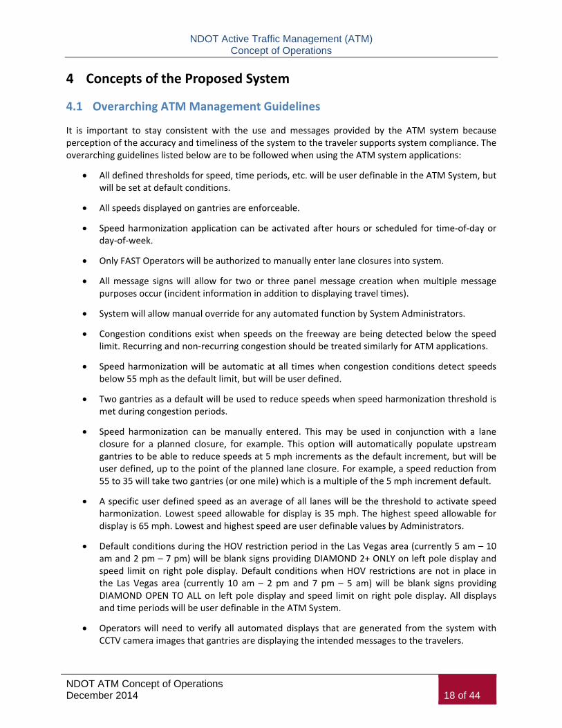
It is important to stay consistent with the use and messages provided by the ATM system because perception of the accuracy and timeliness of the system to the traveler supports system compliance. The overarching guidelines listed below are to be followed when using the ATM system applications:
All defined thresholds for speed, time periods, etc. will be user definable in the ATM System, but will be set at default conditions.
All speeds displayed on gantries are enforceable.
Speed harmonization application can be activated after hours or scheduled for time-of-day or day-of-week.
Only FAST Operators will be authorized to manually enter lane closures into system.
All message signs will allow for two or three panel message creation when multiple message purposes occur (incident information in addition to displaying travel times).
System will allow manual override for any automated function by System Administrators.
Congestion conditions exist when speeds on the freeway are being detected below the speed limit. Recurring and non-recurring congestion should be treated similarly for ATM applications.
Speed harmonization will be automatic at all times when congestion conditions detect speeds below 55 mph as the default limit, but will be user defined.
Two gantries as a default will be used to reduce speeds when speed harmonization threshold is met during congestion periods.
Speed harmonization can be manually entered. This may be used in conjunction with a lane closure for a planned closure, for example. This option will automatically populate upstream gantries to be able to reduce speeds at 5 mph increments as the default increment, but will be user defined, up to the point of the planned lane closure. For example, a speed reduction from 55 to 35 will take two gantries (or one mile) which is a multiple of the 5 mph increment default.
A specific user defined speed as an average of all lanes will be the threshold to activate speed harmonization. Lowest speed allowable for display is 35 mph. The highest speed allowable for display is 65 mph. Lowest and highest speed are user definable values by Administrators.
Default conditions during the HOV restriction period in the Las Vegas area (currently 5 am – 10 am and 2 pm – 7 pm) will be blank signs providing DIAMOND 2+ ONLY on left pole display and speed limit on right pole display. Default conditions when HOV restrictions are not in place in the Las Vegas area (currently 10 am – 2 pm and 7 pm – 5 am) will be blank signs providing DIAMOND OPEN TO ALL on left pole display and speed limit on right pole display. All displays and time periods will be user definable in the ATM System.
Operators will need to verify all automated displays that are generated from the system with CCTV camera images that gantries are displaying the intended messages to the travelers.

NDOT Active Traffic Management (ATM) Concept of Operations
NDOT ATM Concept of Operations December 2014 19 of 44
Camera pre-sets are needed to verify lane control displays on gantries quickly as well as provide FAST Operators with the camera immediately upstream of the back-of-queue to allow for monitoring where speeds are being detected below the speed threshold.
Information displays will be used outside of ATM applications as normal DMS, particularly to provide travel times, public service announcements where applicable, and providing advanced information to support the arterial networks adjacent to I-15 and US-95.
Any lane control display over a lane or on a gantry pole must be submitted to FHWA for approval for experimentation.
These guidelines may be altered once the FAST TMC moves to 24x7 operations or has identified an after-hours trained manager that can verify automated processes when in effect.
4.2 Lane Management System Concept
ATM Technologies Used:
Manual entry into ATM software system of location and lane blocked that will automatically populate the sign sequence upstream of that location chosen.
Lane control signs
Information display
Functional Parameters:
Lane signs will be blank as the default message during “normal conditions”. Travelers will be able to see the ATM gantries and system in use at all times in the form of the HOV restriction display and the speed limit display on the poles of each gantry as warranted.
Managing individual freeway lanes as they are closed or re-opened will be a manual process facilitated by a FAST TMC Operator. NDOT District 1 Operators will not be granted access to close or re-open freeway lanes until NDOT has completed appropriate training.
All lane control designations are shown in Figure 4-1 and includes:
o A green down arrow for warning the traveler that the ATM system has been activated for a reason or that the traveler has passed the reason for ATM system activation.
o A RED X for a closed lane.
o Merge lanes will include left arrow merge, right arrow merge, and a combination merge display.

NDOT Active Traffic Management (ATM) Concept of Operations
NDOT ATM Concept of Operations December 2014 20 of 44
Figure 4-1: Lane Management Displays
HOV lanes will have the two designations available for operators to choose from that would be displayed on the left pole of the gantry not over the travel lanes.
All HOV lane restrictions are shown in Figure 4-2.
Figure 4-2: HOV Restrictions Displays
Operators will need to verify all automated displays that are generated from the system with CCTV camera images that gantries are displaying the intended messages to the travelers.
Merge indications will be used to allow traffic to move over one lane at a time in advance of a lane closure. This means that two merge arrows will not be offered at one gantry in advance of two lane closure because this would not allow proper time for traffic to move over two lanes away from the closed lanes.
Merge left or right arrow display (two arrows on one display) will only be used if one or more of the middle lanes are closed that still offer a left or right lane merge over. This may include opening the HOV lane to all traffic as a merge over lane option for traffic.
Merge left arrow display or merge right arrow display will not be allowed on the right-most lane display sign. Merge left or right arrow will only be used for lanes that offer a left or right lane to merge into. NDOT has determined that shoulder running will not be allowed as part of this ATM system management.
Gantries should be designed to have a numbering system identifier on physical sign. Identifier will support public safety and other responding agencies in communicating what gantries are visible at an incident location.
NDOT Active Traffic Management (ATM) Concept of Operations
NDOT ATM Concept of Operations December 2014 21 of 44
HOV restriction sign should be posted on the left pole gantry display indicating “DIAMOND 2+ ONLY” as the default message.
HOV restriction sign “DIAMOND OPEN TO ALL” should be posted on left pole gantry display only in conjunction with two or more right lanes being closed on the freeway. If congestion is not detected due to the lane closure(s), the first instance of this “DIAMOND OPEN TO ALL” display will be on the same gantry upstream that first provides a merge over arrow display over a lane. If congestion is detected due to the lane closure(s), the first instance of this “DIAMOND OPEN TO ALL” display will be on the same gantry upstream that first provides a reduced speed on lane displays.
HOV restriction sign will be blank if lane closure involves the left-most lane.
HOV restriction sign will have an option within the system to be provided on the lane control sign over the HOV lane.
No lanes will be closed for planned special events. If event lane closures are required, they will be implemented in the form of the Dynamic Merging application (Junction Control).
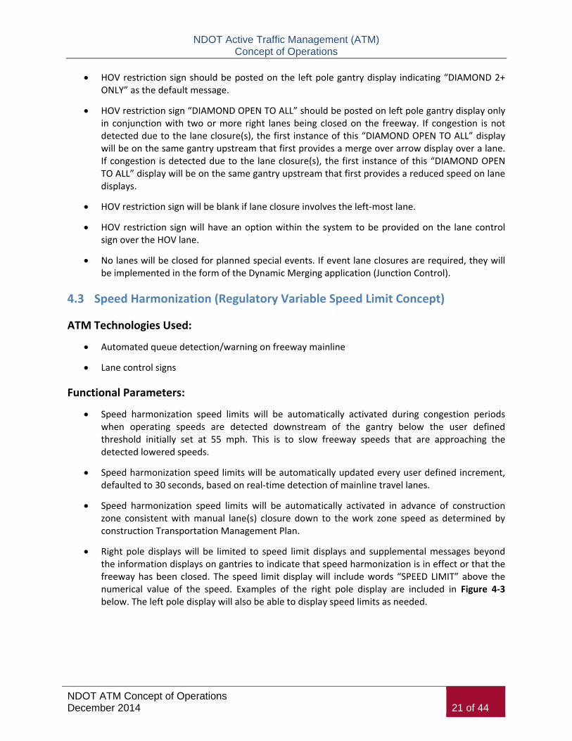
4.3 Speed Harmonization (Regulatory Variable Speed Limit Concept)
ATM Technologies Used:
Automated queue detection/warning on freeway mainline
Lane control signs
Functional Parameters:
Speed harmonization speed limits will be automatically activated during congestion periods when operating speeds are detected downstream of the gantry below the user defined threshold initially set at 55 mph. This is to slow freeway speeds that are approaching the detected lowered speeds.
Speed harmonization speed limits will be automatically updated every user defined increment, defaulted to 30 seconds, based on real-time detection of mainline travel lanes.
Speed harmonization speed limits will be automatically activated in advance of construction zone consistent with manual lane(s) closure down to the work zone speed as determined by construction Transportation Management Plan.
Right pole displays will be limited to speed limit displays and supplemental messages beyond the information displays on gantries to indicate that speed harmonization is in effect or that the freeway has been closed. The speed limit display will include words “SPEED LIMIT” above the numerical value of the speed. Examples of the right pole display are included in Figure 4-3 below. The left pole display will also be able to display speed limits as needed.

NDOT Active Traffic Management (ATM) Concept of Operations
NDOT ATM Concept of Operations December 2014 22 of 44
Figure 4-3: Speed Limit Displays
ROAD CLOSED AHEAD sign on right pole display will not be used if the information display provides the closure message on the same gantry.
“REDUCED SPEED AHEAD” will be provided on right pole display while speed harmonization is providing speeds on all lane displays only when speed on next gantry is being reduced. Example, If the dropped speed limit needs to match 35 mph at the end of congestion, then:
o Gantry A could show 35 MPH SPEED AHEAD on message board with green arrows over lane displays and REDUCED SPEED AHEAD on the right pole display;
o Gantry B downstream of Gantry A could show 35 mph on lane displays with REDUCED SPEED ZONE on message board and SPEED LIMIT 35 MPH on the right pole display; and
o If Gantry C downstream of Gantry B is also detected below the operating speed threshold and is within the congestion zone, the right pole display should show SPEED LIMIT 35 MPH (because the next gantry is the same speed limit, not a reduced speed limit).
Speed harmonization needs to be implemented in response to an actual situation. If users do not believe the system is legitimate, compliance rates will be low. Therefore, if the reason for the new speed limit is not apparent, it should be explained through appropriate signing on the information display sign provided at minimum every other gantry in the direction of travel similar to the Figure 4-4 below. The travel time system providing travel times will provide supplemental information regarding the extent of delay caused by congestion.
Figure 4-4: Information Display Message Example to Support Speed Harmonization Lane Display
Speed limits will be provided between 35 mph and 65 mph in 5 mph increments as the default condition.
Speed limits will be automatically adjusted based on the mainline detection of congestion resulting in the lowering speeds on the freeways for safety purposes.
Speed limits will be reduced based on those actual operating speeds at the gantry experiencing the congestion to the nearest increment ABOVE the current operational speed. The first display for speed harmonization will be upstream of the detected reduced speed.
NDOT Active Traffic Management (ATM) Concept of Operations
NDOT ATM Concept of Operations December 2014 23 of 44
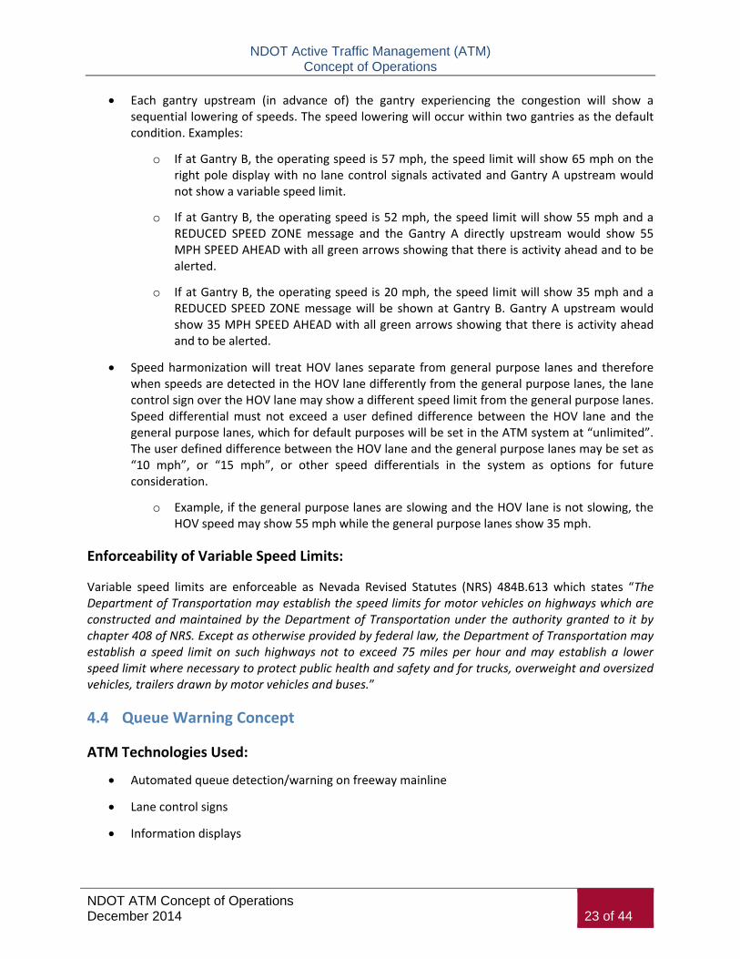
Each gantry upstream (in advance of) the gantry experiencing the congestion will show a sequential lowering of speeds. The speed lowering will occur within two gantries as the default condition. Examples:
o If at Gantry B, the operating speed is 57 mph, the speed limit will show 65 mph on the right pole display with no lane control signals activated and Gantry A upstream would not show a variable speed limit.
o If at Gantry B, the operating speed is 52 mph, the speed limit will show 55 mph and a REDUCED SPEED ZONE message and the Gantry A directly upstream would show 55 MPH SPEED AHEAD with all green arrows showing that there is activity ahead and to be alerted.
o If at Gantry B, the operating speed is 20 mph, the speed limit will show 35 mph and a REDUCED SPEED ZONE message will be shown at Gantry B. Gantry A upstream would show 35 MPH SPEED AHEAD with all green arrows showing that there is activity ahead and to be alerted.
Speed harmonization will treat HOV lanes separate from general purpose lanes and therefore when speeds are detected in the HOV lane differently from the general purpose lanes, the lane control sign over the HOV lane may show a different speed limit from the general purpose lanes. Speed differential must not exceed a user defined difference between the HOV lane and the general purpose lanes, which for default purposes will be set in the ATM system at “unlimited”. The user defined difference between the HOV lane and the general purpose lanes may be set as “10 mph”, or “15 mph”, or other speed differentials in the system as options for future consideration.
o Example, if the general purpose lanes are slowing and the HOV lane is not slowing, the HOV speed may show 55 mph while the general purpose lanes show 35 mph.
Enforceability of Variable Speed Limits:
Variable speed limits are enforceable as Nevada Revised Statutes (NRS) 484B.613 which states “The Department of Transportation may establish the speed limits for motor vehicles on highways which are constructed and maintained by the Department of Transportation under the authority granted to it by chapter 408 of NRS. Except as otherwise provided by federal law, the Department of Transportation may establish a speed limit on such highways not to exceed 75 miles per hour and may establish a lower speed limit where necessary to protect public health and safety and for trucks, overweight and oversized vehicles, trailers drawn by motor vehicles and buses.”
4.4 Queue Warning Concept
ATM Technologies Used:
Automated queue detection/warning on freeway mainline
Lane control signs
Information displays

NDOT Active Traffic Management (ATM) Concept of Operations
NDOT ATM Concept of Operations December 2014 24 of 44
Functional Parameters:
Variable speed limits for the queue warning system will be automatically activated during congestion periods.
Variable speed limits will be automatically activated in advance of construction zone consistent with manual lane(s) closure down to the work zone speed as determined by construction Traffic Management Plan.
Speed limit display will include words “SPEED LIMIT” above the numerical value of the speed. An example of this designation is shown in Figure 4-3.
Merge displays will be displayed on upstream gantries consistent with the ability of traffic to merge over one lane at a time to merge away from the back of queue experiencing 35 mph or slower current operational speeds, or other user defined threshold. Merge displays are provided in Figure 4-1. Merge displays will only be used if current operational speeds are being detected below the user defined threshold.
Caution message will be used only during queue warning messages provided on information displays in combination with speed limit one or more mile in advance of detected queuing traveling under 45 mph, or other user defined threshold, in specific lanes upstream when no other lanes are being detected under 45 mph. An example of the caution message is provided in Figure 4-5 below. If speeds are being detected in more than one lane under 45 mph, the regulatory variable speed limit application will be activated.
Figure 4-5: Queue Warning Caution Lane Display
Queue warning needs to be implemented in response to an actual situation. If users do not believe the system is legitimate, compliance rates will be low. Therefore, if the reason for the new speed limit and lane change suggestions posted on the displays is not apparent, it should be explained through appropriate signing on the information display sign provided every other gantry in the direction of travel similar to the Figure 4-6 on the next page.
Figure 4-6: Information Display Message Example to Support Queue Warning Lane Display
Speed limits will be provided between 35 mph and 65 mph in 5 mph increments as the default condition.

NDOT Active Traffic Management (ATM) Concept of Operations
NDOT ATM Concept of Operations December 2014 25 of 44
Speed limits will be automatically adjusted based on the mainline detection of congestion resulting in the lowering speeds on the freeways for safety purposes.
Speed limits will be reduced based on those actual operating speeds at the gantry experiencing the congestion to the nearest increment ABOVE the current operational speed. The first display for speed harmonization will be upstream of the detected reduced speed.
Each gantry upstream (in advance of) the gantry experiencing the congestion will show a sequential lowering of speeds within two gantries as the default condition in order to match the gantry that is displaying the lowest operational speed where congestion is occurring. Example:
o If at Gantry B, the operating speed is 57 mph, the speed limit will show 65 mph on the right pole display with no lane control signals activated and Gantry A upstream would not show a variable speed limit.
o If at Gantry B, the operating speed is 52 mph, the speed limit will show 55 mph and a REDUCED SPEED ZONE message and the Gantry A directly upstream would show 55 MPH SPEED AHEAD with all green arrows showing that there is activity ahead and to be alerted.
o If at Gantry B, the operating speed is 20 mph, the speed limit will show 35 mph and a REDUCED SPEED ZONE message will be shown at Gantry B. Gantry A upstream would show 35 MPH SPEED AHEAD with all green arrows showing that there is activity ahead and to be alerted.
4.5 Dynamic Lane Merging Concept (Junction Control)
ATM Technologies Used:
Automated queue detection/warning on freeway mainline
Ramp meter presence detection (if applicable)
Lane control signs
Information displays
Functional Parameters:
This ATM application should only be used in unique and isolated circumstances and only after appropriate management has reviewed the situation and approved the operator to perform the lane closure. Locations of application are not specific and may include service interchanges as well as system-to-system interchanges that have on-ramp traffic merging in with mainline traffic.
Acceptable use could be when there are no incidents, no special events, no construction, and no extenuating circumstance that could cause the traveling public to consider this application a “normal” use of the system.
Provided only immediately upstream of on-ramp gantry locations to the freeway where an information display sign is available for message posting. System is designed for Information

NDOT Active Traffic Management (ATM) Concept of Operations
NDOT ATM Concept of Operations December 2014 26 of 44
Display sign to be provided downstream of on-ramp traffic; however, software needs to be designed to maintain this requirements in case of a gantry design change.
One gantry upstream of the on-ramp merge location, an operator will manually close lane next to on-ramp merging lane only if it determined that it is warranted. Possible warrants could include fast approaching mainline speeds, heavy mainline congestion, slow on-ramp speeds, or heavy on-ramp queuing backing up to arterial system. This system will mimic the closure of one lane for an incident or construction event, although this purpose is to allow on-ramp traffic to enter into the first mainline freeway lane accessible with no impeding traffic.
Once lane closure is in effect, operator will need to verify that the automated process through this application overrides the dynamic ramp metering application and turns off the ramp meter that may have been automatically activated based on mainline congested conditions. This will allow ramp traffic to flush onto the freeway mainline.
Upstream gantries from on-ramp where dynamic lane merging will be taking place will be automatically updated to display merging over away from closed lane.
Operator will manually remove lane closed message from lane upstream of on-ramp when operating conditions return to normal.
This application will request ramp meter evaluation by a FAST Operator to determine if the ramp meter should be turned off or if the rate of metering should be increased.
Message displays used are provided in Figure 4-1, 4-2, 4-3 and 4-5. An example information display that could support dynamic merging or junction control is provided in Figure 4-7 below.
Figure 4-7: Information Display Message Example to Support Dynamic Merge System
The Design-Builder of gantries will need to carefully consider the design distance of gantry placement in relation to the on-ramp merging gore point. This is because the freeway lane will be shown as OPEN at the same time as on-ramp traffic is merging onto the freeway which introduces a potential movement conflict. In this scenario, the gantry placement that provides the lane CLOSED display may need to be provided directly prior to the merge point to eliminate the conflict.
4.6 Dynamic Ramp Metering Concept
ATM Technologies Used:
Automated queue detection/warning on freeway mainline
Ramp meter presence detection
Ramp meters

NDOT Active Traffic Management (ATM) Concept of Operations
NDOT ATM Concept of Operations December 2014 27 of 44
Functional Parameters:
Dynamic ramp metering is automatically activated during freeway mainline congestion periods as determined by a preset threshold for congestion.
Dynamic ramp metering may be a useful tool during planned special events or construction to limit the need for dynamic lane merging (junction control).
This application will be linked directly to the dynamic lane merging (junction control) system. The dynamic lane merging application will request ramp meter evaluation by a FAST Operator to determine if the ramp meter should be turned off or if the rate of metering should be increased.
Freeway gantries will only be used during this application to provide on-ramp traffic a current speed limit display on the right side of the first available gantry once merged onto the freeway mainline. The speed limit display provided on the right post of the gantry will be one of two options:
o Posted speed limit of freeway; or
o Automatically generated variable speed limit consistent with overhead display in lane next to merge lane – this will provide an additional display to warn merging traffic that there is a reduced speed limit on the freeway at the time they are merging.
4.7 Software Interface Concept
All ATM functions and related equipment are to be operated from the FAST TMC. The existing CSS software used at the FAST TMC to operate and manage the freeway system is being modified to include new ATM application management. The following are basic needs for the software development for ATM application management:
Software should provide a user-interface for operators that provides the following visual indications to support operations and management of specific applications:
Gantries identified on interface should provide the exact layout and number of lane displays and information signs in order to be as accurate as possible to what is provided in the field.
For the purpose of displaying the sequence of gantries within one display, gantries should be “flattened” to be able to show lane control signs next to one another.
Gantry displays to be able to show exactly what is being displayed at any given moment, including DMS display, lane control display, HOV status, or posted speed.
Color-coded bars or highlights over freeway travel lanes to show green, yellow, and red congestion conditions as they relate to each gantry and interchange location.
Entries for specific lane display and information display signs based on ATM application desired to be in use.
Identifier of which ATM application is in use at any given time.

NDOT Active Traffic Management (ATM) Concept of Operations
NDOT ATM Concept of Operations December 2014 28 of 44
Software is to support the ability to display lane displays (lane open, lane closed, merge left, merge right, and speed display) either through a system-stored or system-generated response strategy or through manual operator request.
ATM software should be flexible enough to implement shoulder-running strategies, at a future time if NDOT desires, for all or specific roadway segments, using pre-developed plans and the use of consecutive green arrow and red X displays as needed.
ATM software should be able to respond to congestion or event triggers to formulate or select a traffic response plan (e.g., HOV lane use permitted by all traffic for short stretches beyond the ends of entrance ramps due to traffic congestion in mainline lanes).
ATM equipment (overhead lane management displays for queue warning and advisory messages, cameras, additional detection, etc.) is to be incorporated into the inventory of “As-Built ITS Devices” and incorporated into appropriate operational and inventory systems.
Inventorying of field equipment is to be facilitated through standardized identification means, such as bar coding of the equipment, unique ID code, as well as the gantry number.
The design and construction of all new ITS applications shall meet interface requirements allowing for expansion of the existing FAST using the correct revision of device firmware. All new ITS technologies shall operate without requiring the installation of new device interface software in the existing FAST central software. The interface between the FMS/ATMS and the new ATM platform needs to be seamless. All ITS technologies mounted on the ATM gantries and flow detectors will be utilized by the central software provided to implement the ATM functionality. The ATM central software will use the existing FAST device interfaces to receive monitoring data from the detectors and to control the signs on the ATM gantries. The ATM System will allow for the ability to add new gantries and devices as FMS expansion occurs.
4.8 Other Concept Considerations
ATM Not in Use
When the ATM technologies are not in use, the following will apply to the system:
Lane control signs will be blank as the default message to travelers. Right pole display on gantry will display speed limit sign and left pole display on gantry will display HOV 2+ ONLY message.
Information Display Signs will provide travel times as a default message along the corridor. When instances warrant additional information, that information will be posted instead of or in conjunction with travel time messaging.
Public service announcements (PSA) consistent with NDOT policies on PSA messages may be added to Information Display Signs while ATM systems are not active.
Resource Considerations
Operators will need training for when to close lanes.
An underlying assumption for all the potential scenarios is that the ATM central software will have logic and decision support capabilities to automatically generate sign displays based on

NDOT Active Traffic Management (ATM) Concept of Operations
NDOT ATM Concept of Operations December 2014 29 of 44
real-time traffic flow data (as collected by the system) and manual operator input. The following decision-making process applies to all ATM scenarios, with the level of operator involvement varying depending on the scenario and type of information required by the system. Operator involvement will include:
Determining and/or verifying problems that may necessitate changes to the ATM sign displays (e.g., incident reported by other sources, including identifying the nature and severity of the problem/number of lanes to be closed) via CCTV and/or communications with State Police and Service Patrols.
Inputting additional information to the system (e.g., number of and which lanes closed, estimated duration of blockage, need for emergency vehicle access) will facilitate the development of a “recommended” signing plan by the ATM logic.
Continuously monitoring operations (i.e., traffic flow, incidents, system) and adjusting the sign displays (with system assistance) will be required as conditions change.
NDOT needs to update the FAST Agreement to develop operational and developmental policies for ATM System.
FAST may need to expand operations to 24x7 business hours in the future to support more automated ATM applications.

NDOT Active Traffic Management (ATM) Concept of Operations
NDOT ATM Concept of Operations December 2014 30 of 44
5 Operational Scenarios
This section provides an overview of the proposed ITS/Operations systems requirements, architecture, and components for the NDOT ATM program, based on a summary of expected operational scenarios. The recommended systems components will assist NDOT and the FAST TMC in meeting the goals and objectives set forth in Section 1 of this ConOps.
5.1 Context Diagram
Functionality for the proposed ATM implementation will be achieved through the deployment and integration of new and existing roadside monitoring and control equipment for collecting data and managing traffic operations, traveler information systems that will provide roadway condition information, and the implementation of ATM decision support and control software at the FAST TMC. The context diagram shown below in Figure 5-1 provides an operational overview of the system, taking into consideration the following major data terminators.
Figure 5-1: NDOT ATM System Operation Context Diagram
The ATM system will collect or react to the following information:
Current roadway, shoulder, incident status or confirmation
Flow data – speed, volume, occupancy data from traffic lanes

NDOT Active Traffic Management (ATM) Concept of Operations
NDOT ATM Concept of Operations December 2014 31 of 44
Roadside images – capture of real-time traffic images from specific locations
Manual request from operator (activation of display, selection of response plan, editing of plan, etc.)
The ATM system will then generate the following information:
Traffic image request – request specific real-time traffic images from specific locations
Request for ATM response confirmation – alerts operator of recommended system response (including operations plan, displays) based on roadway, situation and other inputs
Driver information – Provision of speed, lane status or queue warning displays (for control, regulatory and advisory information displayed on the roadway)
Road status – Provision of traffic flow, lane status, queue information (for traveler information purposes)
This section provides examples of representative scenarios for the proposed NDOT ATM system, identifying how the various strategies and the associated sign displays will operate under a wide variety of circumstances. The examples are not meant to be all-inclusive, but they do provide an understanding of ATM operations given likely events. Operational scenarios addressed in this chapter include the following:
Free Flow
Queue Warning
Incident – with congestion and without congestion
Planned Closure
Full Roadway Closure
Dynamic Merging
Each scenario includes a sequence of gantry displays showing a spatial sequence of ATM signs/DMS mounted on ATM gantries, with the direction of travel being from the bottom of the figure to the top of the figure. The number of lane control signal displays available with vary across the corridor. For the purposes of these scenarios, five lanes were used across the entire scenario for consistency. For the purpose of displaying the sequence of scenarios, gantries were “flattened” to be able to show lane control signs next to one another.

NDOT Active Traffic Management (ATM) Concept of Operations
NDOT ATM Concept of Operations December 2014 32 of 44
5.2 Free Flow Scenario
Figure 5-2 provides an example of the default ATM gantry display usage during free flow conditions when the freeway is not congested or lanes are closed warranting speed harmonization. As shown in the figure, no display (a blank sign) will be provided over the open general purpose lanes, HOV 2+ display will be active on the left pole display on the gantry, and the current speed limit of the roadway is provided on the right pole display on the gantry.
During free flow conditions when ATM applications are not active, the travel time system will be active on gantries as the default messaging.
Manual processes:
None.
Automatic processes:
None.
Figure 5-2: Free Flow Scenario
5.3 Queue Warning Scenario
Bottlenecks and congestion are not limited to just peak periods, especially in Las Vegas near the I-15/US-95 Spaghetti Bowl area. Weekend traffic can become quite heavy during certain hours along with middle of the night shift change peak periods during the week. Under these circumstances, a potential scenario would be to warn traffic in advance of congestion using a combination of queue warning message and speed harmonization displays. This scenario describes the ATM applications that should be in effect during peak period congestion conditions on the freeway. Figure 5-3 shown below describes the scenario of congestion warranting the use of queue warning messages and speed harmonization.
Manual processes:
None.

NDOT Active Traffic Management (ATM) Concept of Operations
NDOT ATM Concept of Operations December 2014 33 of 44
Automatic processes:
Congestion is detected by mainline detection.
Regulatory speeds are separately calculated general purpose lanes and HOV lanes.
Variable speed messages are generated only for general purpose lanes.
Messages are generated for DMS.
Figure 5-3: Queue Warning Scenario
5.4 Incident Scenario
Figure 5-4 shows the sequence of lane control displays and the information display messages for a crash blocking the right lanes during a congested condition that activates speed harmonization due to detected speeds lower than 45 mph. Not only does the ATM close the right lane and merge traffic to the left in advance of the crash location, but there is speed harmonization and queue warning leading up to the merging location away from the lane closed due to the crash. Figure 5-5 shows the sequence of lane control displays during a crash blocking the same right lanes during a non-congested condition. Because there are two or more lanes closed in this scenario, HOV restrictions are lifted (i.e., the HOV lane is

NDOT Active Traffic Management (ATM) Concept of Operations
NDOT ATM Concept of Operations December 2014 34 of 44
opened to all traffic) in the area of the merge and closure process, returning to HOV 2+ beyond the crash site.
Manual processes:
Operator identifies blocked lane(s) and selects RED X to be lanes that are closed to traffic.
Operator sets time value for lane closure(s) with option to extend.
Operator creates or uses available messages for purpose of lane closure near location of closure.
Automatic processes:
Lane indication displays are generated based on operator identified blocked lane(s).
Messages are generated for DMS based on operator identified blocked lane(s).
Variable speed messages are generated only for general purpose lanes.
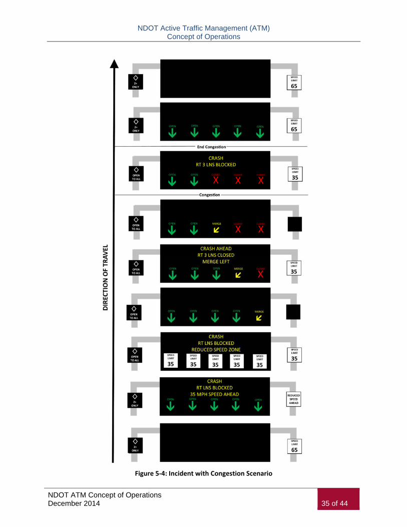
NDOT Active Traffic Management (ATM) Concept of Operations
NDOT ATM Concept of Operations December 2014 35 of 44
Figure 5-4: Incident with Congestion Scenario

NDOT Active Traffic Management (ATM) Concept of Operations
NDOT ATM Concept of Operations December 2014 36 of 44
Figure 5-5: Incident without Congestion Scenario

NDOT Active Traffic Management (ATM) Concept of Operations
NDOT ATM Concept of Operations December 2014 37 of 44
5.5 Planned Closure Scenario
Planned closure cover known lane restrictions that can be planned for in advance such as for work zones or special events. This scenario is shown in Figure 5-6 below. The scenario includes planned lane closures due to a planned event, which in this case is a work zone, and uses the lane indications.
Manual processes:
Operator identifies blocked lane(s) and selects RED X to be lanes that are closed to traffic.
Operator sets time value for lane closure(s) with option to extend.
Operator creates or uses available messages for purpose of lane closure near location of closure.
Automatic processes:
Lane indication displays are generated based on operator identified blocked lane(s).
Messages are generated for DMS based on operator identified blocked lane(s).
Variable speed messages are generated only for general purpose lanes.

NDOT Active Traffic Management (ATM) Concept of Operations
NDOT ATM Concept of Operations December 2014 38 of 44
Figure 5-6: Planned Closure Scenario

NDOT Active Traffic Management (ATM) Concept of Operations
NDOT ATM Concept of Operations December 2014 39 of 44
5.6 Full Freeway Closure Scenario
In the event of a major crash or other event necessitating a complete closure of the freeway, the ATM system can provide advance information to motorists well in advance of the closure, indicating ramps that should be used to exit the roadway. This scenario is shown in Figure 5-7 and includes utilization of information displays to warn travelers of full closure.
Manual processes:
Operator identifies blocked lane(s) and selects RED X to be lanes that are closed to traffic.
Operator sets time value for lane closure(s) with option to extend.
Operator creates or uses available messages for purpose of lane closure near location of closure.
Automatic processes:
Lane indication displays are generated based on operator identified blocked lane(s).
Messages are generated for DMS based on operator identified blocked lane(s).
Variable speed messages are generated only for general purpose lanes.
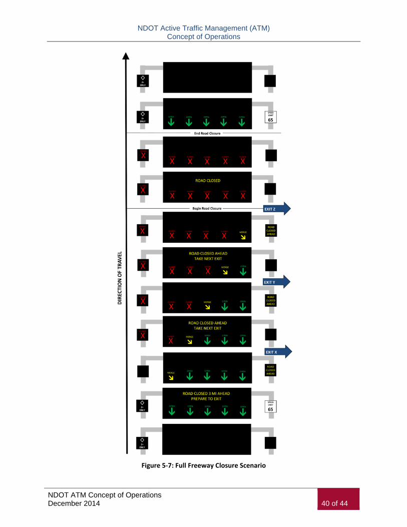
NDOT Active Traffic Management (ATM) Concept of Operations
NDOT ATM Concept of Operations December 2014 40 of 44
Figure 5-7: Full Freeway Closure Scenario
NDOT Active Traffic Management (ATM) Concept of Operations
NDOT ATM Concept of Operations December 2014 41 of 44
5.7 Dynamic Merging Scenario
Dynamic merging (or junction control) is a strategy that dynamically changes lane allocation at interchanges based on mainline and entering or exiting ramp volumes. Figure 5-8 shows an example of this ATM function to enhance the on-ramp merge onto the freeway during a congested period. This application provides a longer merge area using the right general purpose lane of the freeway to allow merging vehicles onto the freeway without incident.
Manual processes:
Operator verifies need for application use and requests manager approval for use of system.
Operator identifies blocked lane(s) and selects RED X to be lanes that are closed to traffic.
Operator sets time value for lane closure(s) with option to extend.
Operator creates or uses available messages for purpose of lane closure near location of closure.
Automatic processes:
Lane indication displays are generated based on operator identified blocked lane(s).
Messages are generated for DMS based on operator identified blocked lane(s).

NDOT Active Traffic Management (ATM) Concept of Operations
NDOT ATM Concept of Operations December 2014 42 of 44
Figure 5-8: Dynamic Merging Scenario
NDOT Active Traffic Management (ATM) Concept of Operations
NDOT ATM Concept of Operations December 2014 43 of 44
5.8 Failure Conditions
The reliability of ITS hardware has continually increased over the years, and the ATM system and software will be designed, integrated, and operated to minimize operational problems. This includes monitoring diagnostics to immediately identify to the FAST TMC Operator when and where a problem has occurred, and the nature of the problem (loss of communications, loss of power).
When failures do occur, ATM signs at a minimum should go “blank”. The ATM system also can be designed such that it will continue to provide the desired functionality, even if this operation is in some form of degraded mode. Potential failure scenarios and the resulting system operation in this regard are noted below:
Loss of power at a sign – All ATM displays will be blank. Power redundancy should at a minimum be considered just for the right pole display to be able to continue to display speed limit signs. This is particularly important because static speed limit signs are being replaced by ATM gantries. NDOT will pursue for each ATM gantry redundancies in power and communication to mitigate potential failure.
Loss of communications at a sign – As noted above, the current communications network incorporates a self-healing ring, which can continue to provide system communications in the event of a failure at a single node or segment. In the event of multiple communication failures, the signs should automatically go to a blank out condition. This is particularly important if loss of communications occurs during a lane closure scenario.
Sign Controller failure – The system architecture has not yet been designed, but assuming that all of the signs for a single sign gantry are operated by a single controller at the gantry, it may be feasible to include a second controller at the gantry as a “hot” standby should the primary controller fail.
Detector failures – Algorithms for calculating and displaying speed advisories will be able to function effectively up to some threshold of missing data. The percentage of detectors failed or number of detectors failed should be administrator settable for speed calculations and for deciding when not to post the speeds. When that threshold is reached, the system will revert to a blank out message. If two consecutive lane detectors fail between gantries, speed harmonization will remain active although will require manager check and override to adjust based on prevailing conditions.
In the event of maintenance needed to the ATM technologies along the corridors, the FAST TMC is in charge of maintenance of all ATM components and will alert the appropriate agency (NDOT and NHP) of the intent to repair to be able to manage appropriate lane closures or other restrictions required of traveled lanes to allow maintenance to occur.
NDOT Active Traffic Management (ATM) Concept of Operations
NDOT ATM Concept of Operations December 2014 44 of 44
6 Public Relations Prior to, or during the construction of the ATM gantries, it would be advantageous of NDOT to pursue a public relations campaign to alert travelers and visitors to the upcoming change to the way they travel in Las Vegas. The public relations campaign should involve strategies within three categories: smart branding, focusing on users rather than technology, and communications methods. Examples of strategies in each category are provided below:
Smart branding:
Create a title or phrase that would help travelers recognize the changes on their highways. Avoid acronyms and engineering jargon;
Consider a logo or style to use in outreach about the new system; and
Assist with the simulation model for the public.
Focus on users rather than technology:
Television and radio commercial providing education on the new system produced for local media outlets that focuses on the driver experience and explains why this technology is needed and how it will improve drivers lives – television version could show corridor flyover;
YouTube video to describe the use of ATM and give examples of situations that it can be used, including use of system; and
Interactive website dedicated on the NDOT website, 511 website, and FAST website that steps drivers through what to expect and how they should react.
Communication methods:
Pamphlet/brochures;
Photo updates on Flickr, Twitter, or Facebook showing the progress of sign testing and a photo album from the inaugural implementation of the program;
Ongoing blog for updates;
Process for public feedback; and
Live video feed along ATM corridors.