Embed Size (px)
Citation preview

English .................... 3 Español ................. 38Português ............. 73
NAV MAN
DIESEL FUEL F L O W S E N S O R S
Installation andOperation Manual
ww
w.n
av
ma
n.c
om

2 Diesel fuel fl ow sensor kit Installation and Operation Manual
FCC Statement Note: This equipment has been tested and found to comply with the limits for a Class B digital device, pursuant to Part 15 of the FCC Rules. These limits are designed to provide reasonable protection against harmful interference in a normal installation. This equipment generates, uses and can radiate radio frequency energy and, if not installed and used in accordance with the instructions, may cause harmful interference to radio communications. However, there is no guarantee that interference will not occur in a particular installation. If this equipment does cause harmful interference to radio or television reception, which can be determined by turning the equipment off and on, the user is encouraged to try to correct the interference by one or more of the following measures: Reorient or relocate the receiving antenna. Increase the separation between the equipment and receiver. Connect the equipment into an output on a circuit different from that to which the
receiver is connected. Consult the dealer or an experienced technician for help. A shielded cable must be used when connecting a peripheral to the serial ports.

Diesel fuel flow sensor kit Installation and Operation Manual 3NAVMAN
Contents
Contents ................................................................................................. 3 Important ................................................................................................ 5 1 Introduction .................................................................................. 6 1-1 Diesel fuel flow sensor features ................................................. 6 1-2 A typical system ........................................................................... 7 A diesel flow sensor .....................................................................................7
1-3 The bypass valve .......................................................................... 7 2 Understanding boat performance data ...................................... 8 Boats ............................................................................................................8 Fuel Consumption ........................................................................................8 Engine RPM .................................................................................................8 Boat Speed ..................................................................................................8
3 Plotting a fuel consumption curve ............................................. 9 3-1 Fuel consumption table ............................................................. 12 Notes on filling out this table ......................................................................12
3-2 Understanding the fuel consumption curve ............................ 14 A typical fuel consumption curve ................................................................14 Understanding your fuel consumption curve ..............................................14 Note on fuel usage .....................................................................................14
4 Measuring your propeller’s performance ................................ 15 Propeller size .............................................................................................15 Slip factor ...................................................................................................15 Calculating the slip factor ...........................................................................15 Understanding your slip factor ...................................................................16
5 Measuring engine performance ................................................ 17 5-1 Engine power and propeller curves ......................................... 17 The theoretical propeller load curve ...........................................................18
5-2 Specific fuel consumption curve .............................................. 19 6 Diesel fuel flow sensor hardware ............................................. 20 6-1 What comes with your diesel fuel flow sensor kit .................. 20 6-2 Options and accessories ........................................................... 20 Filtering the fuel ..........................................................................................20
6-3 Sensor fittings ............................................................................ 21

4 Diesel fuel flow sensor kit Installation and Operation Manual NAVMAN
7 Installing the diesel flow sensor kit .......................................... 22 Installation sequence .................................................................................22
7-1 Twin engine installations ........................................................... 22 7-2 Notes on pipes, fittings and installation .................................. 23 7-2-1 Pipe ..........................................................................................................23 7-2-2 Flare Nuts ..................................................................................................23 7-2-3 Flexible Hoses. ..........................................................................................23 7-2-5 Threadseal tape or paste ............................................................................23
7-3 Planning where the parts of the kit will be fitted ..................... 25 7-3-1 Overview ....................................................................................................25 7-3-2 Mounting a sensor ......................................................................................25 7-3-3 Locating the sensors in the fuel lines .........................................................26 Locating the supply sensor ........................................................................26 Locating the return sensor .........................................................................26 Sensor mounting positions .........................................................................26
7-4 Installing the temporary straight through pipes ..................... 28 7-4-1 Installing a through pipe with flare joints into a copper pipe run ................29
7-5 Test running and installing the sensors ................................. 31 7-6 Installing the tachometer pickup .............................................. 33 Locating the tachometer pickup .................................................................33 Installing the tachometer pickup .................................................................34
7-7 Installing the cables ................................................................... 35 7-7-1 Link and tachometer cables .......................................................................35 7-7-2 Connecting to a DIESEL 3200 ...................................................................35
Appendix A Specifications ................................................................. 37

Diesel fuel flow sensor kit Installation and Operation Manual 5NAVMAN
It is the owner’s sole responsibility to install and use the instrument and its sensor(s) in a manner that will not cause accidents, personal injury or property damage. The user of this product is solely responsible for observing safe boating practices.
Fuel type: Navman diesel flow sensors (metal) and DIESEL 3200 instruments have been specifically developed for use in marine applications with diesel engines and are not warranted for any other type of application. These sensors and instruments must NOT be used with petrol (gasoline) engines.
Fuel formulation: Every effort has been made by the manufacturer to ensure that the materials used in the Navman fuel flow sensor(s) will operate reliably with different fuel mixtures. The manufacturer or its distributors can not be held responsible for fuel formulation or any affect this may have on the performance and durability of the fuel flow sensor(s).
Back pressure: A diesel fuel flow sensor will create additional back pressure in a fuel system of an estimated 0.3” of mercury at 25 US gallons /hour (100 litres/hour) and 1.5” of mercury at 80 US gallons per hour (300 litres/hour).
It is the owners responsibility to ensure that fitting the fuel flow sensor(s) does not cause fuel starvation which may lead to poor engine performance.
Fuel Computer: Fuel economy can alter drastically depending on the boat loading and sea conditions. The fuel computer should not be the sole source of information concerning available fuel onboard and the electronic information should be supplemented by visual or other checks of the fuel load. This is necessary due to possible operator induced errors such as forgetting to reset the fuel used when filling the tank, running the engine with the fuel computer not switched on or other operator controlled actions that may render the device inaccurate. Always ensure that adequate fuel is carried onboard for the intended trip plus a reserve to allow for unforeseen circumstances.
Specific requirements: Your boat’s fuel installation boat might be subject to specific requirements (such as USCG, NMMA and ABYC guidelines or local laws), particularly if the boat is licensed, surveyed, charted or inspected. It is the owner’s sole responsibility to install and use the instrument and its sensor(s) in compliance with these requirements.
NAVMAN NZ LIMITED DISCLAIMS ALL LIABILITY FOR ANY USE OF THIS PRODUCT IN A WAY THAT MAY CAUSE ACCIDENTS, DAMAGE OR THAT MAY VIOLATE THE LAW.
Governing Language: This statement, any instruction manuals, user guides and other information relating to the product (Documentation) may be translated to, or has been translated from, another language (Translation). In the event of any conflict between any Translation of the Documentation, the English language version of the Documentation will be the official version of the Documentation.
This manual represents Navman’s Diesel fuel flow sensor kit as at the time of printing. Navman NZ Limited reserves the right to make changes to specifications without notice.
Copyright © 2004 Navman NZ Limited, New Zealand. All rights reserved. Navman is a registered trademark of Navman NZ Limited.
Important

6 Diesel fuel flow sensor kit Installation and Operation Manual NAVMAN
The Navman diesel fuel flow sensor kit measures the fuel consumption and RPM of your diesel engined boat. But that is a gross understatement of the capabilities of this powerful diagnostic tool. This manual is written to help you understand the many functions the system can perform, and to help you interpret the numbers it can provide. We also give some basic information on some of the factors which can influence boat performance, and what the various readings from the sensors can reveal about your boat. Hopefully, by understanding more, you will no longer think of the engine as just a noisy and expensive mystery.
In the end we should be able to help you make your boating experience more relaxing, safer, more economical and better informed.
1 Introduction
1-1 Diesel fuel flow sensor features A positive displacement flowmeter, with
one moving internal part - there are no fine pointed shafts and jewelled bearings to get worn or hammered by diesel pulsing.
Diecast aluminium housing. A direct flow bypass valve, to take the
sensor out of the fuel line if required. Low pressure drop across the sensor. Simple, in-line installation, much like a
primary fuel filter. The inlet and outlet ports have a
commonly-available thread: a ¼ NPT parallel female thread on sensor is used with a ¼ NPT taper male thread on the fitting.
No restrictions on pipe geometry on entry or exit from sensor.
Supplied with temporary straight through pipes to make installation safer.
Factory tested and calibrated - sensors
This manual describes: How to install a diesel fuel flow sensor kit
onto a diesel engine (sections 6 and 7). How to understand and interpret the fuel
sensor readings (sections 2 and 3). How to use the fuel flow readings to
understand and optimise your propeller and engine performance (sections 4 and 5).
Note that this fuel flow sensor kit does not have a display. The kit must be installed with a Navman marine instrument to display the fuel readings, such as the DIESEL 3200. A second sensor kit can be fitted for twin engine boats.
It is vital to read this document and the Navman display instrument’s installation and operation manual before installing or using this kit.
do not normally require calibrating again.
Each engine is fitted with two fuel flow sensors. One sensor, in the the fuel supply line measures flow from tank to engine. The other sensor, in the fuel return line measures flow from the engine back to the tank.
The flow sensor system calculates the engine consumption from the supply and return flow rates. It compensates for: Reverse flow pulsing from diaphragm lift
pumps. Different fuel temperatures in the supply
and return lines - as fuel heats up it expands and its viscosity changes
The flow characteristics of the sensors.
The system also has a tachometer to measure the engine RPM with digital accuracy.
The system reports the fuel flow, total fuel consumed and engine RPM over a serial digital information link to the Navman instrument to display the fuel data.

Diesel fuel flow sensor kit Installation and Operation Manual 7NAVMAN
1-2 A typical system
Tachometer cable
Supply fuel line Primaryfilter
Return fuel line
Link cable
Dieselengine
Supplyflow
sensor Dieseltank
Returnflow
sensor
Sensor cable
Tachometerpickup
Display unit,such as aDIESEL 3200
Other connector(s) Other wiring and
connection to sensors on a second engine (optional)
These parts are includedin a diesel flow sensor kit
A diesel flow sensor
1-3 The bypass valve Each flow sensor is fitted with a bypass valve:
Fuel inlet / outlet port
Bypass valve (see below)
Two electrical connectors (underneath)
Fuel inlet / outlet port
Mounting bracket
Bypass valve
Normal position, fuelflows through sensor
Bypass valve
Bypass position, fuel flows directly from the sensor inlet to the outlet and does not pass through the sensor - bypass the sensor if you suspect the sensor is not working properly
Identification band:Blue: Supply line sensorRed: Return line sensor LED, blinks when fuel is passing
through sensor (underneath)

8 Diesel fuel flow sensor kit Installation and Operation Manual NAVMAN
As with all measurements, you will get no meaningful data if you do not have accurate instruments. Once you have accurate fuel consumption, boat speed and engine speed figures, then the true power of the diesel flow sensors can be used.
Boats All boats are different - even consecutive boats off a production line can be quite different in performance. So there is no real ‘generic’ data that can be applied to your particular boat/engine/propeller combination.
Fuel Consumption The simplest set of information you can get from the diesel flow sensors is fuel consumption - US Gallons per nautical mile or Litres per mile. This figure will depend on many factors - the condition of the hull (clean or fouled), the loading and trim of the boat, wave and wind conditions. Over time you will get an idea as to how different conditions affect the performance of your boat.
Engine RPM Engine revolutions per minute (RPM) is the single most important item in any instrument package, as it is the base line against which such things as boat speed, fuel usage, and propeller efficiency are measured - if your base line is inaccurate all the readings using it are inaccurate. Accuracy is all important.
Many rev counters supplied with engines are not very accurate, and should be recalibrated after they have been installed in your vessel. Navman have designed a tachometer as part of the diesel flow kit. The tachometer measures engine RPM digitally, with timing derived from the highly accurate crystal running the whole system. This digital tachometer never needs calibrating.
Boat Speed Check that your boat speed instrument is reading correctly. If necessary, recalibrate boat speed as described in the instrument’s operation manual.
Remember that there are two distinct ways to describe the movement of a boat - speed through the water, and speed over the ground. In still water with no tides or currents then these two speeds produce the same reading; otherwise they are quite different, and you need to be sure you are using the correct one: Speed through the water is usually read
from a paddle-wheel sensor. Use this speed to check your boat’s performance and fuel consumption.
Speed over ground is usually read from a GPS receiver. Use this speed to work out maximum range, fuel reserve and time of arrival.
2 Understanding boat performance data

Diesel fuel flow sensor kit Installation and Operation Manual 9NAVMAN
A fuel consumption curve gives a picture of how fuel consumption varies with engine RPM, and allows you to select an economical cruising speed for the given conditions. By plotting fuel consumption curves for different boat and weather conditions, you can understand how fuel consumption, economy and range vary with different conditions.
When you first get your Navman diesel flow system installed on your boat, perform a test run and plot a fuel consumption curve. For your first test run, choose a calm day, with light wind and little current; have a typical load aboard and a freshly cleaned hull.
Then you can plot other fuel consumption curves for different boat, weather or sea conditions. Compare these with your first curve to see how your boat’s performance changes with conditions. These curves will be the reference curves for your boat. As time goes by you can refer back to this set of reference data - you can plot another fuel consumption curve under the same conditions and compare it to the reference curve to check how your boat’s performance is changing over time.
To plot a fuel consumption curve for given conditions:
1 Take a series of readings of the fuel flows and boat speed at different engine revs and fill out the fuel consumption table (see section 3-1)
2 Plot the data from the fuel consumption table on a graph. Either photocopy the graph on the next page or download a copy from www.navman.com. On the one graph, plot:
a Boat speed (column 5) against engine RPM (column 1)
b Economy (column 6) against engine RPM (column 1)
Section 3-2 shows a typical graph.
3 Interpret this curve to understand your boat performance (see section 3-2).
3 Plotting a fuel consumption curve
10 Diesel fuel flow sensor kit Installation and Operation Manual NAVMAN
Speed - knots
Dis
plac
emen
t Cra
ft
Economy - L / nautical mile
0
500
1
000
15
00
2
000
25
00
3
000
18
15
12 9 6 3 0
1.2
1.0
0.8
0.6
0.4
0.2
0

Diesel fuel flow sensor kit Installation and Operation Manual 11NAVMAN
Speed - knots
Pla
ning
Cra
ft
Economy - L / nautical mile
0
500
1
000
15
00
2
000
250
0
300
0
30
25
20
15
10 5 0
6 5 4 3 2 1 0

12 Diesel fuel flow sensor kit Installation and Operation Manual NAVMAN
Date Weather Conditions
Vessel Sea State
Displacement
Load aboard
Gearbox ratio Passengers aboard
Engines Water Tanks
Fuel Tanks
Propeller
Max. Fuel Capacity
Working fuel capacity (max x 0.9)
Notes on filling out this table Start at a slow speed. Allow a minute or two for the boat to settle to its speed and trim and for the display readings to stabilise. Then write the displayed fuel flow(s) and boat speed in a line of the table on the right, as described below. Then increase the engine revs by another 100 or 200 rpm, wait a minute or two for the readings to stabilise and repeat the readings. Take readings up to the maximum service RPM of your engine.
Column 1 - Engine RPM Use the Navman tachometer reading if possible, to be sure of accurate results. Write the engine RPM in column 1.
Columns 2 and 3 - Fuel consumption Units are litres or gallons - we presume you will want to work in the units you are familiar with, and that you have set-up the system display to work in gallons or litres.
For a single engine boat, write the flow rate in column 2. For a twin engine boat, write the port engine flow rate in column 2 and the starboard engine flow rate in column 3. The numbers for each engine on a twin engine boat should be very similar.
Column 4 - Total fuel flow rate This is just the sum of the port and starboard engine figures. Add together the flow rates in column 2 and 3 and write the sum in column 4.
Column 5 - Boat speed Write the boat speed through the water in
column 5. Remember that speed through the water is not the same as GPS speed if there are any tidal or other currents.
Column 6 - Economy If there is a speed instrument connected to the display then this number can be read directly for each rpm setting. Write the economy in column 6. Otherwise, to calculate gallons per nautical mile divide the consumption in gallons/hr (column 4) by the speed in knots (column 5); or to calculate Litres per nautical mile divide the consumption in L/hour (column 4) by the speed in knots (column 5). Write the answer in column 6.
Column 7 - range This is for future reference. Note - please use the range calculated as an indication, rather than as a range that you know you can achieve. For safety’s sake it is strongly recommended that the calculation is done using 90% of the full fuel capacity - that will leave 10% of the tank as a reserve. Call this 90% value the working capacity of the fuel tank. Also note that the range would apply only in calm conditions - difficult wind or sea conditions will drastically reduce the distance you can go on a full tank. A more heavily loaded boat will also have its range reduced.
To get the maximum range for each engine rpm setting, take the economy (the number in column 6) and multiply it by the working capacity of the fuel tank. Write the range in column 7.
3-1 Fuel consumption table Photocopy this page or download a copy from www.navman.com

Diesel fuel flow sensor kit Installation and Operation Manual 13NAVMAN
1 Column 2 Reading 3 Reading 4 Calculate 5 Reading 6 Calculate 7 Calculate
E n g i n e RPM
Fuel Flow
L / h r o r G a l . / h r Single or port
Fuel Flow L / h r o r G a l . / h r Starboard
Total flow L / h r o r Gal./hr Both 2 + 3
S p e e d Naut. m/hr (Knots)
Economy L / N a u t . mile or Gal pe r Nau t mile
Range
On full tank Naut. Miles
400
800
1000
1200
1400
1600
1800
2000
2200
2400
2600
2800
3000

14 Diesel fuel flow sensor kit Installation and Operation Manual NAVMAN
Understanding your fuel consumption curve Notice that while the speed is constantly increasing as the engine RPMs increase, the economy figure usually has a dip in its curve, as shown above. The high consumption before the dip is caused by the boat trying to climb up over its own bow wave. This is a very inefficient speed to try to operate the boat at.
The drop in consumption at the dip occurs as the boat gets up onto the plane. Thereafter, as you would expect, the faster you go the more fuel is consumed.
If your graph shows such a dip, then running the engine at the corresponding RPMs (1300 in the example above) will give the best speed for the least fuel consumption.
Note on fuel usage A significant feature of diesel engines is
3-2 Understanding the fuel consumption curve
A typical fuel consumption curve Boats which plane will produce curves similar to the example below. The curve will change with boat and sea conditions.
that engine RPM alone does not dictate the amount of fuel the engine is demanding. A diesel engine’s governor will hold the engine at the RPM you set. The amount of fuel it uses at that RPM is determined by the load on the engine.
If you are sliding down the surface of a big wave like a surfer then very little power is required, so to hold the RPM you have selected requires very little fuel. Conversely, if the load increases because you are battering into a head sea, have a build-up of growth on the hull, or your propeller is damaged or covered in barnacles it is going to require a lot more fuel to maintain that same RPM. SO, an engine’s thirst is determined by load, not the RPM which it is being asked for.
Understanding that point will be necessary when we discuss propeller and load curves later.
Spe
ed -
kno
ts
Engine RPM
Eco
nom
y -
L / n
autic
al m
ile
600 800 1000 1200 1400 1600 1800
24
20
16
12
8
4
0
12
10
8
6
4
2
0
Note: If the boat does not plane, there will be no dip in economy as illustrated.
Speed
Economy

Diesel fuel flow sensor kit Installation and Operation Manual 15NAVMAN
The propeller is the final link in the chain that decides if your vessel is a peak performer or just another boat. The best hull and the strongest engine will be wasted unless your propeller is the right size and shape.
From the fuel consumption curve, you can very simply work out how well your propellers are working. The performance of a propeller is measured by its slip factor, and this section describes how to calculate the slip factor of your propeller.
Propeller size First of all, a few basics on propellers. Propellers are described by a series of numbers - nearly all propeller people seem to prefer inches to the metric measurement. For example if a propeller is described as 24 x 21 then: The diameter is 24 inches, The pitch is 21 inches. The pitch is the
theoretical distance the propeller would move forward through the water for each full turn.
Slip factor In reality, because water is a liquid and some of it will sneak around the edge of the propeller blades, the boat will not move forward by the pitch for every turn of the propeller. This is called the “slippage” or slip factor. The amount of slip depends on many things - shape of hull, any rudders, struts, keels etc near the propeller.
Calculating the slip factor It is very useful to work out the slip factor for your propeller.
You will need to know:- A boat speed and RPM setting. Use the
boat speed at maximum rated engine RPM:
a Either use figures you have taken from the fuel consumption table (see section 3).
b Or run the boat at the maximum rated engine revs and note the revs and boat speed through the water.
The ratio of the gearbox(es) on your boat - this will be a number typically between 1 and 3.
The pitch of your propeller in inches.
First calculate theoretical speed:
1 Take the engine RPM and divide by the gearbox ratio. This will give you the number of revolutions per minute the propeller turns.
2 Multiply this number by the pitch of your propeller in inches. This gives the number inches forward per minute, if there was no slip.
3 - Multiply this number by 60. This gives the number of inches forward per hour.
4 - Divide this number by 72912. (72912 is the number of inches in a nautical mile)
As an equation it is:-
Theoretical speed = RPM x pitch x 60 . Gearbox ratio 72912
The answer is the theoretical speed, for the chosen RPM, if there was no slippage. The units are nautical miles per hour (knots).
Because of slippage, the actual speed you were able to achieve is less than the theoretical speed.
To find the slip factor (as a percentage):
1 Take the theoretical speed you worked out above.
2 Subtract the actual speed of the boat to get the difference in speed.
3 Divide this by the theoretical speed.
4 Multiply by 100 to express it as a percentage.
As an equation it is:-
Slip factor (percentage) = Theoretical speed - Actual speed x 100 Theoretical speed
4 Measuring your propeller’s performance

16 Diesel fuel flow sensor kit Installation and Operation Manual NAVMAN
Understanding your slip factor Now, some slip is always to be expected. This slip factor varies with different types of hull, and typical slip factors are - A propeller encased in an aperture behind
a keel, as in a yacht: 40%. A hard chine planing hull with a full keel,
or deadwood: 30% to 35%.
· A hard chine planing hull with little or no keel: 25% to 30%.
Twin engined planing hulls: 18% to 25%.
If your calculations show you have a slip factor that is much more than the figure above, then further investigation is warranted. The propeller may be the wrong size for the present engine, or it might have got damaged, or there may be a fitting on the hull that is disturbing the flow ahead of the propeller. Propellers like to bite into undisturbed water, and will not work efficiently if water is aerated or churned up.
If the propeller is undersize, then it drills a hole in the water, and the engine’s excess power just makes frothy water.
If the propeller is oversize for the engine, the engine will not be able to reach its maximum operating RPM. The engines speed governor will still try to achieve that RPM, and will open up the throttle and pour as much fuel into the engine as it can. If the engine can’t generate any more power at that RPM, all that extra fuel just ends up as heat, and that’s when things get really expensive if the situation persists for any length of time. Be warned - over propping an engine will drastically shorten its life.
An excellent book with lots more information and analysis of propellers is “Propeller Handbook” by Dave Gerr (ISBN 0 7136 5751 0).

Diesel fuel flow sensor kit Installation and Operation Manual 17NAVMAN
300
250
200
150
100
50
0
Engine curves are published by the manufacturer of every engine. If you do not have the curve for your engine, ask your marine dealer for the curve.
Usually there will be several curves showing the different characteristics of your engine
5 Measuring engine performance
In the above graph:
a The top line shows the maximum power that the engine is able to provide at each engine rpm setting - the amount that would be available if you were to ask for it. This curve will be published by your engine manufacturer.
b The lower line shows the propeller load curve. This is amount of power required to propel the boat, with the engine doing those RPM (Remember that usually there is a gearbox between the engine and propeller - for all this discussion we will refer to the RPM of the engine, not the RPM of the propeller itself).
It takes a set amount of power (hp or kW) to drive a particular hull at a particular speed, and it doesn’t matter what the engine is, or how much extra power might be available, or what rpm and gearbox ratio you use. It is roughly equivalent to the power required to tow the boat through the water. So the lower curve represents the power that the propeller draws from the engine, or the load that the propeller puts onto the engine.
This propeller load curve (the lower line in the above graph) depends on many things, and is unique to your boat. The propeller load curve depends obviously on the diameter and pitch of the propeller, but also on the hull shape around
5-1 Engine power and propeller curves
- horsepower, fuel consumption etc, each plotted against engine revs.
The curve we want to discuss is the power (horsepower or kW) versus engine RPM. The curve will look something like this:
Pow
er -
hor
sepo
wer
Engine RPM
600 800 1000 1200 1400 1600 1800 2000 2200 2400
Maximum engine RPM
Propeller load
Power

18 Diesel fuel flow sensor kit Installation and Operation Manual NAVMAN
and ahead of the propeller, the degree of fouling of the hull, and the amount of weight aboard. You will probably not be able to find the exact propeller load curve for your boat, but knowing the general shape of the curve will help you understand how your boat performs.
The important thing to notice is that, for a correctly sized propeller, the engine is loaded to the maximum only at the maximum RPM. (that is where the two curves meet) At all RPM less than maximum, the engine, if it were asked to, could actually generate more power than the boat requires.
For example, at 1200 rpm this engine is capable of generating 250 horsepower, but at those engine revs the boat only needs about 125 horsepower transmitted through the propeller.
This is where the governor on the marine engine comes into play. The throttle on a boat behaves quite differently from the accelerator pedal in a car. It does not directly control the amount of fuel the engine burns. The boat throttle levers just set the rpms at which you want the engine to turn - that is all. The injector and governor system of the diesel engine then works out how much fuel it needs to feed into the engine to keep the engine turning at that speed. If you ask for 1500 rpm with your boat heavily loaded and with a lot of fouling on the hull, the engine will do 1500 rpm, but use a lot more fuel compared to how much it would use if lightly laden and clean.
The theoretical propeller load curve For those interested, the theoretical propeller load curve for a correctly chosen propeller follows the form of:
Propeller load = K x RPM y
Where:
y is a number that is determined by the type of boat. The value of y can range from around 2.2 for ducted propellers to around 3 for slow, heavy commercial boats. The most common value of y is around 2.7, and for medium to high speed pleasure boats, y is usually around 2.7.
K is deliberately chosen to make the curve pass through the point on the engine power curve that is max revs/max power.
To work out K for a pleasure craft use:
Some engine manufacturers will plot an ideal propeller load curve on their engine data sheets, using an exponent of 2.7.
K = Maximum engine power
Maximum engine RPM 2.7
Diesel fuel flow sensor kit Installation and Operation Manual 19NAVMAN
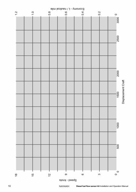
Most engine manufacturers publish graphs of the specific fuel consumption for their engines.
Specific fuel consumption is a graph showing how much fuel the engine burns to produce one horsepower (or kW) for one hour. Each engine has a particular RPM range where it burns the least amount of fuel to produce one unit of power. Some engines are designed to work most efficiently at high RPM, others at low RPM. Modern lightweight diesels commonly have a most economical and efficient speed of operation at around 70 to 80% of maximum rated RPM.
The specific fuel consumption curve is worked out for the engine working at its rated load, at the RPM settings along the bottom of the graph.
As you can see from the discussion on engine and propeller curves (see section 5-1), the only point where the engine is working at its rated load should be at maximum RPM. At any speed less than the maximum RPM, the engine is not working to its maximum, and often well below its maximum. So the specific fuel consumption curve is of limited use to get overall boat fuel consumption. It will give you an indication of whether your engine has been designed for high or low speed efficiency.
Sometimes a manufacturer will also give a curve of fuel consumption for that engine when matched to the theoretical ideal propeller. This will give you a reasonable estimate of the fuel consumption of your engine, provided you have a well chosen propeller. It will not, of course, take into account different loads carried or sea state, or any other factor that affects the actual fuel consumption.
One rule of thumb you can use to estimate fuel is that a modern, large, high efficiency diesel, when averaged out over most of its operating range, will produce 23hp for one hour from one US gallon of fuel (3.33 kW for one hour out of 1 litre of fuel). That is quite a good engine.
Smaller, older, less efficient engines might sink as low as only 19 horsepower for one hour from one US gallon of fuel (3.11 kW for one hour from 1 litre of fuel)
Over all the engines available in the pleasure craft market there is very little difference in the fuel burning rate, when averaged out over their normal working range. Some engines will have an optimum at lower revs, others at higher revs.
The important thing to remember is that the quantity of fuel you actually use is determined by your propeller and hull much more than by your particular choice of engine.
5-2 Specific fuel consumption curve

20 Diesel fuel flow sensor kit Installation and Operation Manual NAVMAN
6 Diesel fuel flow sensor hardware
6-2 Options and accessories
6-1 What comes with your diesel fuel flow sensor kit
From your Navman dealer: Extension cables for the sensor, link and
tachometer cables. Each diesel flow sensor kit measures
data from one engine. A second kit can be fitted if the boat has twin engines and twin tanks.
Filtering the fuel The primary fuel filter will filter all particles larger than typically 25 to 50 microns.
The clearances within the sensor are more than 100 micron, so provided there is an adequate primary filter there will be no problems with particles in the fuel interfering with the sensor. If there isn’t an adequate primary filter, then
the secondary filter will be quickly blocked, and any effects on the sensor will be the least of the problems on the boat!. But just in case your primary filter fails, the sensors are equipped with a by-pass valve - one quick turn and the entire mechanism is bypassed (see section 1-3).
Also supplied: Self adhesive reflective tape for tachometer, alcohol wipe for cleaning where this tape will be placed, warranty card, this manual
The two sensors are distinguished by a different coloured band around the body. The supply line sensor has a blue band (think cooler fuel) and the return line sensor has a red band (think warmer fuel, after it has been through the engine).
Diesel flow sensor for
supply line
Diesel flow sensor for return line
Sensor cable for DIESEL 3200.
20 m (65 ft) longWhite connector
Link cable. 2 m (6 ft) long
Brown connectors
Tachometer pickupwith cable
4 m (13 ft) long Yellow connector
Two straight through pipes for installation
or to replace the sensors if they are
removed
From a marine, hydraulic or diesel dealer: Fittings to connect the two sensors to the
fuel lines (see section 6-3).

Diesel fuel flow sensor kit Installation and Operation Manual 21NAVMAN
Each sensor inlet or outlet requires one or more fittings to connect it to the fuel line. The fuel sensor connections are all ¼ NPT taper thread, fixed female.
The fittings required will vary with where in the fuel lines the sensors are installed. For a discussion of the issues involved, see section 7-3-3.
You will need threaded barrel adaptors to suit the piping on your boat. Because there are so many different threads and piping sizes around the world there is no possibility of having all the adaptors required supplied from Navman. The Navman fuel sensors are supplied with a standard ¼ NPT female thread for the inlets and outlets. Any reasonable marine store, hydraulic or diesel fitting supply house will have a selection of threaded barrel adaptors that will have ¼ NPT male thread on one end, and the appropriate thread for your particular boat on the other. It is preferable to use ¼ NPT thread, but if necessary a ¼ BSP male threaded fitting will fit in a ¼ NPT female thread.
There are many types of pipe and pipe fittings, and it can get very confusing. If you are wanting adaptors to fit a particular fitting on your boat, if
6-3 Sensor fittings at all possible remove that fitting from the boat and take it into the fitting store. It will save a lot of time and doubt. Be sure to cover the exposed ends of the pipes and fittings on your boat to prevent dirt entering, and make allowances for some fuel that may well drip from the pipes while you are away at the store.
Frequently the supply line to the engine is larger in diameter than the fuel return line. Measure both before you go to get the fittings.
Fuel sensors are often connected to solid copper pipe with flare joints. Each connection requires a flare nut to fit the pipe and a barrel union to connect the flare nut to the sensor. For example, to connect a 3/8 inch OD pipe to a sensor requires: A 3/8 inch flare nut A 3/8 inch flare to ¼ NPT taper thread
barrel union fitting
You will need to know the diameter of the fuel pipe (see section 7-2-1). Fitting a flare joint is described in section 7-4-1. This requires the use of a pipe cutting tool, a flaring tool, possibly pipe bending tools, and flare nuts.

22 Diesel fuel flow sensor kit Installation and Operation Manual NAVMAN
Installation sequence The fuel lines are modified and temporary straight through pipes fitted where the sensors will be fitted. The engine is run, then the real sensors are fitted. This procedure ensures that debris from the installation does not enter the sensors.
The recommended installation sequence is:
1 Read this manual and the documentation that comes with the other parts. Read section 7-1 for background information on fuel pipes and fittings.
2 Plan the installation and choose where the fuel flow sensors and cables will be located (see section 7-3). Choose suitable fittings for connecting the sensors to the fuel lines (see section 6-3)
3 Install temporary straight through pipes in the fuel line where the sensors will later be fitted (see section 7-4).
4 Bleed the fuel lines and test run the engine. Then remove the two straight through pipes and fit the two fuel flow sensors (see section 7-5).
6 Install the tachometer (see section 7-6).
7 Install the cables to link the parts of the system together and to the Navman display instrument (see section 7-7).
8 Setup the Navman instrument to use the fuel flow sensors and tachometer, as described in the instrument’s installation and operation manual. Take the boat on a test run and check that the sensors are performing correctly.
If you are unsure where a part should be installed, mount and wire the part temporarily, without cutting holes in the boat. After the sea trials have been completed, install and wire the part permanently.
7 Installing the diesel flow sensor kit
Correct installation is critical to the performance of the unit. Before starting installation, it is vital to read this manual and the documentation that comes with the other parts.
Ensure that any holes that you cut will not weaken the boat’s structure. If in doubt, consult a qualified boat builder.
One important thing to stress is the need for cleanliness in the installation process. Diesel engines, and the Navman sensors are built to fine tolerances - do not allow any dust, dirt, water or particles to enter the fuel system.
DAMAGE WILL RESULT if you ignore this warning.
Warnings
If the boat has twin engines then a second diesel flow sensor kit can be fitted and connected to the same Navman instrument. To install the kits, fit a kit to each engine, following the instructions above for each engine and tank. At the display unit, connect the sensor cables from the two kits in parallel (see section 7-7-2).
The sensors need to be identified as port and starboard in the display unit. You may find more instructions included in the display head manual.
7-1 Twin engine installations

Diesel fuel flow sensor kit Installation and Operation Manual 23NAVMAN
This section discusses fuel pipes terminology and the fittings and tape used to join the pipes.
7-2-1 Pipe Diesel fuel lines are often solid copper pipe. Copper pipes are rated by their diameter: Usually fuel lines will be called by their
outside diameter (OD) - this is also typical of refrigeration pipe fittings.
However, domestic copper water pipe is commonly measured by its inside diameter (ID).
So ½ inch refrigeration pipe is a different size from ½ inch water pipe - make sure you know what size your boat fuel piping is before you purchase fittings to install the sensors.
7-2-2 Flare Nuts Flare nuts are often used to connect a sensor to a solid copper fuel line. There are two different systems of flare fittings: 45 degree flare: 45 degree fittings are
more common, and are in standard use for refrigeration pipe work.
37½ degree flare: 37½ degree fittings are more common for hydraulic systems. JIC fittings are 37½ degree flare.
Fitting flare nuts
Push the flare nut along the pipe before flaring the pipe!! Then flare the end of the pipe using the flaring tool. Inspect the inside face of the flared pipe - it must be smooth and scratch-free. If it is not, cut it off and try again.
7-2-3 Flexible Hoses. Flexible hoses can make installation a lot easier, but modern recommendations are that only one short length of flexible hose should be used - on the final link from the pipework fixed to the boat to the engine, to allow for flexing and vibration.
In many countries a boat licensed to carry paying passengers has stringent codes of installation practice to comply with - frequently these require fixed, rigid fuel piping until the last section. If your boat has to meet such inspections, then check carefully before attempting to use flexible hoses. At the very least you may have to use metal braided flexible hose to meet fire regulations.
There are also recommendations that the fittings on the end of the flexible hose should be professionally hydraulically crimped on. Failing that, there are recommendations on specific forms of field fitted hose fittings. Check the use of flexible hoses against Coast Guard recommendations, ABYC guidelines or with a marine surveyor before deciding to use flexible hose on your boat.
7-2-5 Threadseal tape or paste Threadseal tape or paste is needed for all joints where thread to thread sealing is required, for example the adaptor fitting threads that are screwed to the diesel fuel flow sensor.
Some manufacturers say to never use tape, only use paste, while others say tape is OK. Follow any requirements given by the engine or boat manufacturer. The one thing you must guard against with either type of threadseal is bits of the thread sealer breaking off and getting into the fuel.
Warning: Make sure pieces of the threadseal tape or paste can not break off and enter the fuel pipe.
7-2 Notes on pipes, fittings and installation
Only use fittings with the same flare in your system. Do not mix fittings with different flares.
If you don’t know how to use a flare tool, then don’t fit a fuel flow sensor at your first attempt. Ask to be shown how to use the tool, then practice on some scrap pipe before working on the pipes on your boat!.
Warnings for flare nuts
Here are some comments and reminders: Mark the pipe where you wish to cut it,
then cut it using a pipe cutter. Do not cut the pipe with a hack saw - it
will leave small metal particles in the pipes that will harm the sensor and other items in the fuel line.

24 Diesel fuel flow sensor kit Installation and Operation Manual NAVMAN
If you do use tape, then to prevent pieces of tape from breaking off: Make sure you wind the tape on to the
male thread so that the first couple of threads remain uncovered; do not cover all of the threads.
Be careful when snapping off the tape that threads of tape do not fall back over the end of the fitting.
If removing fittings from previous installs make sure the male threads are cleaned of any remnants of the thread sealer used. If re-using any fittings with female threads be particularly careful about removing remnants of thread seal - it is hard to see on an internal thread.

Diesel fuel flow sensor kit Installation and Operation Manual 25NAVMAN
Locate the two sensors and the tachometer reasonably close together to allow for neat and tidy cable routing. Supplied with the sensors are the sensor cable (20 m (65 ft)); the link cable (2 m (6 ft)) and the tachometer cable (4 m (13 ft)). Extension cables are available for all of these cables.
7-3 Planning where the parts of the kit will be fitted Plan where all the parts will be located before starting to install the parts.
7-3-1 Overview
Mount the fuel flow sensor horizontally
Allow for easy access to plug and unplug the cables.
Bypass valve.Allow for easy access to the bypass valve
Do not install the sensor where it will get wet from water in the bilges.
7-3-2 Mounting a sensor
Attach the sensors firmly to a vertical panel or mounting block on the boat. While the sensors are not heavy, they should not be left hanging from the pipework. Over time vibration and heavy pounding from rough seas could lead to the fuel lines fracturing, with tragic consequences.
Have the electrical
connectors facing down
Two flow sensors are fitted. The supply flow sensor has a blue band, the return flow sensor a red band.
Tachometer cable
Supply fuel line Primaryfilter
Return fuel line
Yellow connector
Link cable
Dieselengine
Supplyflow
sensor Dieseltank
Returnflow
sensor
Sensor cable
Brown connector
Brown connector
White connector
Tachometerpickup
Display unit,such as aDIESEL 3200
Other connector(s)
It does not matter which sensor pipe is the inlet and which is the outlet
Other wiring and
connection to sensors
on a second engine
(optional)

26 Diesel fuel flow sensor kit Installation and Operation Manual NAVMAN
7-3-3 Locating the sensors in the fuel lines The supply sensor will be installed in the fuel supply line between the the primary fuel filter and the engine fuel intake. The return sensor will be installed in the fuel return line between the engine fuel return and the fuel tank. There are several options where to locate each sensor, discussed below, and the best option will depend on the layout of your engine’s fuel system and what fittings are used. Because there is so much variation in fuel systems, this can only be a guide to where the sensor should be located. If in doubt, consult a qualified diesel engineer.
Locating the supply sensor Before planning where to install the sensor, identify the supply line of the fuel system: Find the primary filter - this will be in the
fuel line coming from the fuel tank, before the lines reach the engine. To meet modern recommendations these lines will probably be of metal tubing, not flexible hose. The primary filter is typically large and has a clear sightglass and water and sediment separation bowl. It should be fixed firmly to the structure of the boat.
Find the outlet of the primary filter - this should be labelled on the filter. Sometimes there is a one-way or non-return valve fitting on the outlet also.
Identify the fuel supply line from the primary filter to the engine. A solid fuel line usually has a flexible portion joining it to the engine.
There are four options of locating the supply sensor in the supply line:
1 On the outlet of the primary filter (see a below).
2 In the solid fuel line between the primary filter and the engine (see b below).
3 At the junction of the solid pipe and the flexible hose leading to the engine (see c below).
4 After the lift pump (see d below).
Locating the return sensor Before planning where to install the sensor, identify the return line of the fuel system. This return line will most probably start from the injector body on the engine, have a flexible section to take account of engine movement, then return to the tank in solid wall pipe.
There are three options of locating the return sensor in the return line:
1 At the junction of the solid pipe and the flexible hose leading from the engine (see c below).
2 In the solid fuel line between the engine and the tank (see b below).
3 On the return inlet of the fuel tank (see e below).
Sensor mounting positions This section discusses issues relating to the different mounting positions for supply or return sensors.
a On the outlet of the primary filter(supply sensor only)
Install the sensor after any one-way or non-return valve fitting on the outlet of the filter. This might be the best option if the fuel line is all flexible.
Note: You have to recognise and obtain the
correct fitting to match the fitting on the outlet of the filter.
The diesel flow sensor has a female thread. Connection to a filter with a female thread outlet, will require two fittings, a male to free rotating female and a male to male.
Ensure there is little strain on the sensor or the filter. When using solid fittings, the sensor mounting block must be made accurately and the sensor positioned accurately. If the installation requirements allow, use a short length of flexible fuel hose between the filter outlet and the sensor.

Diesel fuel flow sensor kit Installation and Operation Manual 27NAVMAN
The fuel line to the engine needs to be connected to the outlet of the sensor. If the fuel line is solid copper, a flare joint is probably easiest to install (see section 6-3). Note that if the flaring fails you will need to cut the flare off the copper pipe - this can be a problem if the fuel line is straight or the line can not be shuffled along in its retaining clamps.
b In a solid fuel line (supply or return sensor)
See section 7-4-1. This is usually the easiest option to find fittings for.
The sensor can be located anywhere along the pipe, which might make mounting easier.
You will need to cut the pipe and will usually fit flare joints. This method does require using a flaring tool, and possibly a pipe bender.
c At the junction of the solid pipe and the flexible hose leading to the engine(supply or return sensor)
This can be the best option because there is less potential to strain the sensor fittings.
If possible, fit the sensor inlet to the existing fitting on the solid fuel line and fit the sensor outlet to the flexible fuel line. This requires space for the sensor. You must obtain the exact fittings to match those on the end of the pipe.
Another option is to cut the solid fuel line line and connect the sensor using a flare joint.
In all cases, the sensor must be mounted solidly to the boat. Get a fitting to adapt the sensor outlet to flexible fuel line.
d After the lift pump (supply sensor only)
If the engine is very sensitive to pressure drop in the fuel line, then it may be necessary to install the supply line flow sensor after the lift pump.
The Navman diesel flow sensor has a very low pressure drop across it at moderate flow rates (see appendix A). If your engine has particularly high flow rates in the fuel lines, and if it can not tolerate any pressure drop in the line before the lift pump (on the suction side of the lift pump), then it might be necessary to install the flow sensor in the fuel line after the lift pump.
This is often more difficult than the other options, because the lift pump is usually mounted on the engine and the fuel line from the lift pump to the injector body is steel tube. However, being after the lift pump does get rid of any of the problems of pressure drop across the sensor.
If the sensor is mounted on the engine, then the high temperature and vibration can affect the accuracy of the sensor. It is better to mount the sensor on the boat and connect it with two flexible fuel lines if your requirements allow this.
e On the return inlet of the fuel tank (return sensor only)
Install the sensor before any existing fittings on the fuel tank. This might be the best option if the fuel line is all flexible. Note: You have to recognise and obtain the
correct fitting to match the fitting on the inlet of the tank.
The diesel flow sensor has a female thread. Connection to a tank with a female thread inlet, will require two fittings, a male to free rotating female and a male to male.
Ensure there is little strain on the sensor or the tank. When using solid fittings, the sensor mounting block must be made accurately and the sensor positioned accurately. If the installation requirements allow, use a short length of flexible fuel hose between the sensor outlet and the tank.
The return fuel line needs to be connected to the inlet of the sensor. If the fuel line is solid copper, a flare joint is probably easiest to install (see section 6-3). Note that if the flaring fails you will need to cut the flare off the copper pipe - this can be a problem if the fuel line is straight or the line can not be shuffled along in its retaining clamps.

28 Diesel fuel flow sensor kit Installation and Operation Manual NAVMAN
7-4 Installing the temporary straight through pipes Before fitting the straight through pipes, plan where the sensors will be fitted (see section 7-3). This section describes how to fit the temporary through pipes where the flow sensors will be fitted. The actual sensors are not fitted until later, after the engine has been checked (see section 7-5).
1 Wear gloves to protect your hands from the diesel fuel.
2 Turn OFF the fuel tap at the outlet of the boat’s fuel tank.
3 Put a tray of rags under the pipe where you will cut it to absorb the fuel that will spill.
4 Disconnect or cut the fuel line where the supply and return sensors will be fitted.
To cut solid pipe, use a pipe cutter. Do not use a hack saw - it will leave small metal particles in the pipes that will harm the sensor and other items in the fuel line.
5 Fit the temporary through pipes in the supply and return pipes where the sensors will be fitted. Note: The two flow sensors will be mounted
horizontally, with the wire connectors underneath. It does not matter which fuel connection is the inlet and which is the outlet (see 7-3).
The exact details of how you fit the through pipes will depend on where you are installing the through pipes and the configuration of your engine installation. Instructions for the common case of installing the pipe in the middle of a solid copper pipe run are given in section 7-4-1. If in doubt, consult a qualified diesel engineer.
Apply thread sealer to the all fittings (see section 7-2-5)
Warning: Make sure pieces of the threadseal tape or paste can not break off and enter the fuel pipe
Do up the fittings tightly with the correct tool. The through pipe has flats for attaching a spanner or wrench.
However, when fitting the through pipe in the supply line, tighten the inlet connection but leave the outflow connection loose temporarily.
Keep a real sensor on hand and use it to check for available space, that the fuel line aligns with the sensor ports, and that the cables and connectors will not be difficult to get to later.
When the sensors are fitted later they must be firmly attached to a panel in the boat or a mounting block. If necessary, fit the mounting block now. Check that the sensor can be attached to the boat without straining the pipe joint.
6 Carefully open the fuel tap at the fuel tank until fuel drips from the joint at the outlet of the through pipe in the supply line. This should have filled the pipe and first joint with fuel - meaning there will be less air in the system that has to be bled out to start the engine. Turn the tap off.
Note that there is no need to expel air from the return pipe - it will happen automatically when the engine starts and fuel starts flowing.
7 Tighten the connection on the outflow side of the supply through pipe with the correct tools.
8 Do not leave diesel soaked rags in the boat when you have finished - they are a fire hazard. Take them out and dispose of them properly.
9 Test run the engines (see section 7-5).

Diesel fuel flow sensor kit Installation and Operation Manual 29NAVMAN
Panel
Remove clamps to release pipe
Hold pipe away from panel
1
2
Cut pipe with pipe cutter
Fit barrel unions to a sensor temporarily. Do not apply threadseal. Do up the unions loosely.
7-4-1 Installing a through pipe with flare joints into a copper pipe run
This describes how to install a through pipe with a flare joint. For the full procedure, follow the steps of section 7-4.
Fitting a flare joint requires the use of a pipe cutting tool, a flaring tool, possibly pipe bending tools and flare nuts. To take the example of a 3/8 OD inch pipe, you will need to find from a fitting supplier, for each flare joint: a 3/8 inch flare nut a 3/8 inch flare to ¼ NPT taper thread
barrel union some Teflon® tape or Teflon® threadseal
paste.
If the pipe is fixed to a panel, such as a beam or bulkhead, you will have to release it and bend the pipe out to be able to cut it. Mark the pipe where you wish to put the sensor and cut it using a pipe cutter. Do not use a hack saw.
65 mm (2.5 in)
At least 50 mm (2 in)
straight
Cut pipe to exact length with pipe cutter
3 Hold sensor in place
If necessary, bend the pipe in an ‘S’ curve to align it with the sensor port, 65mm (2.5”) out from the surface where the sensor will be mounted. Hold the sensor in place by hand to check that the pipe lines up with the sensor port.
Gentle, large radius bends can be made by bending the pipe around a curved former by hand, but take care not to kink or crush the tube. If room is restricted and you must form tight radius bends then you will have to use a pipe bending tool.
Do not bend the pipe too close to the end - you must have at least 50mm (2”) or more of straight pipe to allow the flare nut on and still have room for the flaring tool to work.
If necessary, use the pipe cutter to cut the pipe to the exact length to match the sensor port. Do not make the curves too tight and do not cut the pipe short. It is also wise to allow for the possibility that you might make a mistake on the flaring process, and have to cut your first attempt off and start again. It is better to allow for the possibility, than to cut the pipe to absolutely the shortest possible.
Top view
Top view

30 Diesel fuel flow sensor kit Installation and Operation Manual NAVMAN
5 7
6
Install the required fittings to the straight through pipe (for flare joints use a barrel union fitting):
1 Apply thread sealer to the fitting’s ¼ NPT threads.
Warning: Make sure pieces of the threadseal tape or paste can not break off and enter the fuel pipe (see section 7-2-5).
2 Screw each fitting in to the through pipe. Use a spanner or wrench on the fitting and another on the flats of the through pipe.
It does not matter which way round the through pipe goes in the fuel line.
To attach a flare joint at the other end of the sensor, repeat steps 3 and 4 above to bend and cut the pipe, fit a flare nut and flare the end of the pipe. Cut the pipe to length so the flared end will meet the fittings on the sensor port exactly. The exact amount you cut out will depend on how much pipe length was used up in the bends.
Otherwise, attach a different type of fitting following the manufacturer’s instructions.
Hold the sensor in place and hand tighten the fittings to check that the pipe lines up with the sensor port and there is little strain on the joints. Adjust the pipe bends so that the sensor will sit flat against your chosen mounting surface.
Hold sensor in place
Put the flare nut on the pipe first!! Then flare the end of the pipe using the flaring tool. Inspect the inside face of the flared pipe - it must be smooth and scratch-free. If it is not, cut the end of the tube off and try again.
Put flare nut on first
4
Flare end of tube
Fit the straight through pipe. Tighten each fitting with the correct tools (for a flare joint, use a spanner or wrench on the flare nut and on the barrel union). The fitting needs to be tight to prevent leakage. Replace any pipe clamps that you removed earlier.
Note: Leave the flare nut on the outlet side of the install pipe loose now (see section 7-4, step 5).

Diesel fuel flow sensor kit Installation and Operation Manual 31NAVMAN
7-5 Test running and installing the sensors
This section describes how to test run the engine and then install the flow sensors in place of the straight through installation pipes:
1 When you have both supply and return lines connected up and all fittings tightened, bleed the fuel lines. This is the same procedure you use after changing a fuel filter - consult your engine manual.
2 Turn on the fuel tap at the tank. Run the engine for 5 minutes. This will flush any particles that you have introduced in the installation process into the supply line down to the secondary filter. Any particles in the return line will be flushed back to the tank. Check for pipe leaks.
3 Once you are happy with the pipework changes, turn off the fuel tap at the tank.
4 Wear gloves to protect your hands from the diesel fuel.
5 Put a tray of rags under the pipe where you will disconnect it to absorb the fuel that will spill.
6 Undo the fittings on the straight through pipes and remove the straight through pipes. Remove the ¼ NPT adaptors from the ends of the install pipe. Clean the thread sealer from the threads in the install pipes and fittings.
Hand tighten the connections.
10 Screw the sensor to the mounting block or support panel with the screws supplied.
11 Do up the fittings tightly with the correct tool, except for the fitting on the outflow side of the sensor in the supply line. Leave this loose temporarily.
On flare nuts, use a spanner or wrench on the flare nut, and another on the flats of the barrel union. Flare nuts need to be
Tip: Keep the straight through pipes in a safe place near to the sensors - you may want them if you ever have to remove the sensors, for service or to move the system to another boat. If you have the straight through pipe you can just put it in
the gap where the sensor came from, and no re-work of the pipework is necessary.
7 Apply new threadseal to the ¼ NPT adaptor threads (see section 7-5-2).
Warning: Make sure pieces of the threadseal tape or paste can not break off and enter the fuel pipe (see section 7-2-5).
8 Screw the adaptors into the real sensor.
Do not overtighten the adaptors - the sensor body is diecast aluminium and applying too much force when tightening the adaptors will strip the threads.
9 Put the sensor in position: Fit the sensor with the blue band in
the supply line. Fit the sensor with the red band in the
return line.

32 Diesel fuel flow sensor kit Installation and Operation Manual NAVMAN
tight to prevent leakage.
12 Carefully open the fuel tap at the fuel tank until fuel drips from the joint at the outlet of the sensor in the supply line. This should have filled the pipe and first joint with fuel - meaning there will be less air in the system that has to be bled out to start the engine. Turn the tap off.
13 Tighten the fitting on the outflow side of the supply sensor with the correct tool.
On a flare nut, use a spanner or wrench on the flare nut, and another on the flats of the barrel union. Flare nuts need to be tight to prevent leakage.
14 On both sensors, turn the bypass valve to vertical (normal operation).
15 When you have both supply and return lines connected up and all fittings tightened, bleed the fuel lines. This is the same procedure you use after changing a fuel filter - consult your engine manual.
16 Turn on the fuel tap at the tank. Run the engine for 5 minutes. Check for pipe leaks.
17 Do not leave diesel soaked rags in the boat when you have finished - they are a fire hazard. Take them out and dispose of them properly.
18 Continue with installation (see section 7-6).

33 Diesel fuel flow sensor kit Installation and Operation Manual NAVMAN
This section describes how to install the tachometer pickup. The tachometer is optional and need not be installed, however the tachometer gives a precise measurement of engine RPM, essential for measuring engine fuel consumption at different speeds.
The pickup operates by sending a beam of pulses of infrared light towards the crankshaft pulley. A piece of reflective tape applied to the crankshaft pulley reflects the beam back to the pickup, where an infra-red receiver detects the light pulses. A light on the sensor will light up when its detector is receiving enough reflected light to operate properly.
Locating the tachometer pickup It is important that the reflective tape is attached to part of the crankshaft, such as the flywheel or a pulley. Do not attach the tape to any part that is not rotating at the same RPM as the crankshaft, such as a pulley driven accessory.
The optimum distance from the pickup to the reflective tape is about 50 mm (2 in) away from the reflective tape. If it is positioned closer than 25 mm (1 in) to most flywheels or pulleys then enough infra red will be reflected back from the surface of the wheel to trigger the pickup. Further away than about 75 mm (3 in) and not enough infrared is reflected from the reflective tape, so the pickup is never triggered.
The pickup does not have to be at right angles to the face of the tape - up to 45° each way is permitted.
The pickup should be mounted on the boat, not the engine. Some angle is beneficial. The tachometer pickup has a built in 4 metre (12 ft) cable to connect it to the return sensor. Locate the tachometer so that the cable run is accessible, neat and tidy. An extension cable can be fitted if required.
7-6 Installing the tachometer pickup
Rotatingflywheel or pulley
Infra-red light from tachometer
When tape is under tachometer, light is reflected back to tachometer
Piece of reflective
tape
Reflective tape
Tachometer about 50 mm (2 in) from reflective tape
Tachometerpickup up to45° from a right angle
Tachometer pickup up to 45° from a right angle
Tip: Mount the sensor, power it on, then place the reflective tape where the light strikes the pulley.

34 Diesel fuel flow sensor kit Installation and Operation Manual NAVMAN
Installing the tachometer pickup Warning: The pickup is fitted near a rotating part of the engine. Make sure you do not touch any rotating part. Mount the pickup firmly so it will not break off and fall into the engine. When working near the engine, do not wear loose loose clothing; tie back long hair.
1 Clean any grease or dirt off the area where you are going to stick the reflective tape. Wipe the area with a cloth or tissue, then use the alcohol wipe provided to degrease the surface.
2 Peel the self-adhesive backing from the tape and stick it in position on the rotating part.
3 Fit a mounting block for the tachometer. Remember the engine will move and rock on its flexible mounts. Make sure the mounting bracket is strong so that it will not vibrate when the motor runs or in a heavy pounding sea.
3 Continue with installation (see section 7-7).

35 Diesel fuel flow sensor kit Installation and Operation Manual NAVMAN
Once the flow sensors and tachometer pickup have been installed, install the cables.
When installing a cable: Keep the cable away from sources of
electrical signals or electrical noise. Route the cable neatly and out of harms
way. Do not crush, pinch or strain the cable. Secure the cable with cable ties or
insulated electrical staples at regular intervals; run the cable in cable ducting; or restrain it in some other way.
Ensure no connectors or exposed terminals are in the bilge.
7-7-1 Link and tachometer cables Link cable The link cable to link the supply sensor to the return sensor is 2 m (6 ft) long and has connectors with brown collars:
1 Plug one end into the connector on the supply sensor with a brown nut. Turn the collar to lock the connection.
2 Route the cable securely and out of harms way to the return sensor. If required, fit an extension cable.
3 Plug the end into the connector on the return sensor with a brown nut. Turn the collar to lock the connection.
Tachometer cable The cable from the tachometer to the return sensor is 4 m (13 ft) long and has a connector with a yellow collar:
1 Route the cable securely and out of harms way from the tachometer to the return sensor. Secure the cable well so it will not get caught up in any moving machinery, or get melted by hot engine surfaces. If required, fit an extension cable.
2 Plug the end into the connector on the return sensor with a yellow nut. Turn the collar to lock the connection.
7-7-2 Connecting to a DIESEL 3200 The sensor cable from the supply sensor up to the DIESEL 3200 display is 20 metres long. It has a connector with a white collar on one end and bared tinned wires on the other:
1 Plug the sensor cable connector into the connector on the supply sensor with a white nut. Turn the collar to lock the connection.
2 Route the sensor cable securely and out of harms way up to the display unit. If necessary, fit an extension cable.
3 Connect four wires at the end of the sensor cable to four of the wires of the DIESEL 3200 power/data cable, matching the colours (see below). Use a Navbus junction box or any simple wire to wire connector system to join the wires.
4 Install the DIESEL 3200 - follow the instructions in the DIESEL 3200 Installation and Operation Manual. Connect the four sensor cable wires to the DIESEL 3200 power/data cable, matching the wire colours.
In a twin engine boat, wire the second sensor cable in parallel with the first, matching the wire colours.
7-7 Installing the cables
Red
Orange
Black
Blue
One or two sensor cables,wire in parallel, match colours

36 Diesel fuel flow sensor kit Installation and Operation Manual NAVMAN
Tachometer cable
Supply fuel line Primaryfilter
Return fuel line
Yellow connector
Link cable
Display unit,DIESEL 3200
Dieselengine
Supplyflow
sensor Dieseltank
Returnflow
sensor
Sensor cable
Brown connector
Brown connector
White connector
Tachometerpickup
Note: The diesel sensors can be used in 12 or 24 V DC systems. Some display units, such as the DIESEL 3200 require 12 V DC. Before connecting any power greater than 12 V DC to the display unit, check that the unit can tolerate the intended voltage.
Note: Each flow sensor has an LED underneath, between the connectors. Check that the LED blinks when fuel is passing through the sensor.
Optional paddlewheel speed sensor cable, blue plug
Black
Red
External alarm (optional)
Fuel transducer (white plug)
White
Green
Yellow
Orange Blue
Speed transducer (blue plug)
NavBus (optional)
-
NMEA in (GPS, optional)NMEA out (optional)
Ignition Switch
Fuse
}
12 VDC

Diesel fuel flow sensor kit Installation and Operation Manual 37NAVMAN
Appendix A Specifications
General: Size: 60mmHx129mmWx93mmD
Weight: 300g Per sensor
Supply Voltage: 12-24v DC
Current Consumption: 25mA @ 12 VDC
Recommended Operating ambient temperature: 5 degrees C to 70 degrees C
Maximum Operating ambient temperature: -29 degrees C to 80 degrees C
Flow Rates: Max 400L/h and Min of 25L/h
Standards and Compliance:
EMC USA: FCC Part 15 Class B.
Europe: (CE) EN64000-6-1 and EN64000-6-3.
New Zealand and Australia: (C-Tick) AS-NZS 3548.
Environment: IPx6
IPx7
ABYC H33
7/98 Diesel Fuel Systems

108 Manual de instalação e utilização do kit de sensor de fluxo de gasóleoNAVMAN
Anexo B - Como contactar-nos www.navman.com NORTH AMERICABNT - Marine Electronics30 Sudbury Rd, Acton, MA 01720.Toll Free: +1 866 628 6261Fax: +1 978 897 8264e-mail: [email protected]: www.navman.comOCEANIAAustraliaNavman Australia Pty. LimitedSuite 2, 408 Victoria RoadGladesville NSW 2111, Australia.Ph: +61 2 9879 9000Fax: +61 2 9879 9001e-mail: [email protected]: www.navman.comNew ZealandAbsolute Marine Ltd.Unit B, 138 Harris Road,East Tamaki, Auckland.Ph: +64 9 273 9273Fax: +64 9 273 9099 e-mail: [email protected] New GuineaLohberger Engineering,Lawes Road, Konedobu.PO Box 810, Port Moresby.Ph: +675 321 2122Fax: +675 321 2704e-mail: [email protected]: www.lohberger.com.pgLATIN AMERICAArgentinaCostanera Uno S.A. Av Pte Ramón S. Castillo y Calle 13Zip 1425 Buenos Aires, Argentina.Ph: +54 11 4312 4545Fax +54 11 4312 5258e-mail:
[email protected]: www.costanerauno.arBrazilEquinautic Com Imp Exp de Equip Nauticos Ltda.Rua Ernesto Paiva, 139 Clube dos Jangadeiros Porto Alegre - RS - Brasil CEP: 91900-200.Ph: +55 51 3268 6675 +55 51 3269 2975Fax: +55 51 3268 1034e-mail:
[email protected]: www.equinautic.com.brRealmarineEstrada do Joa 3862, Barra da Tijuca, Rio de Janeiro, Brazil. CEP: 22611-020.Ph: +55 21 2483 9700Fax: +55 21 2495 6823e-mail: [email protected]: www.realmarine.com.brChileEquimar Manuel Rodrigurez 27Santiago, Chile.Ph: +56 2 698 0055Fax +56 2 698 3765e-mail: [email protected] VennikColon 1148, Talcahuano, 4262798, Chile.Ph: +56 41 541 752Fax +56 41 543 489e-mail: [email protected]
MexicoMercury Marine de MexicoAnastacio Bustamente #76Interior 6 Colonia Francisco Zarabia, Zapapan, Jalisco, C.P. 45236 Mexico.Ph: +52 33 3283 1030Fax: +52 33 3283 1034web: www.equinautic.com.brUruguayAlvaro Bermudez, Nautica11300 Montevideo, Uruguay.Ph & Fax: +59 82 628 6562e-mail: [email protected]
ASIAChinaPeaceful Marine Electronics Co. Ltd.Guangzhou, Hong Kong, Dalian, Qingdao, Shanghai1701 Yanjiang Building195 Yan Jiang Zhong Rd. 510115 Guangzhou, China.Ph: +86 20 3869 8839Fax: +86 20 3869 8780e-mail: [email protected]: www.peaceful-marine.comIndiaAccess India Overseas Pvt. Ltd.A-98, Sector 21, Noida - 201 301, India.Ph: +91 120 244 2697TeleFax: +91 120 253 7881Mobile: +91 98115 04557e-mail: [email protected] Export EnterprisesBlock No. F-1, 3rd Floor, Surya TowersSardar Patel Rd, Secunderbad 500 003.Ph: +91 40 2784 5163Fax: +91 40 2784 0595e-mail: [email protected]: www.esmario.comKoreaKumhomarine Technology Co. Ltd.#604-842, 2F, 1118-15, Janglim1-Dong, Saha-Gu, Busan, Korea.Ph: +82 51 293 8589Fax: +82 51 265 8984e-mail: [email protected]: www.kumhomarine.comMaldivesMaizan Electronics Pte. Ltd.Henveyru, 08 Sosunmagu. Male', Maldives.Mobile: +960 78 24 44Ph: +960 32 32 11Fax: +960 32 57 07e-mail: [email protected] and Malaysia, Brunei, Indonesia and PhillipinesRIQ PTE Ltd. Blk 3007, 81 Ubi Road 1, #02-440, Singapore 408701.Ph: +65 6741 3723Fax : +65 6741 3746e-mail: [email protected] International CorporationNo. 281, Hou-An Road, Chien-Chen Dist. Kaohsiung, Taiwan R.O.C. Ph: +886 7 831 2688Fax: +886 7 831 5001e-mail: [email protected]: www.seafirst.com.tw
ThailandThong Electronics (Thailand) Co. Ltd.923/588 Ta Prong Road, Mahachai, Muang, Samutsakhon 74000, Thailand.Ph: +66 34 411 919Fax: +66 34 422 919e-mail: [email protected] [email protected]: www.thongelectronics.comVietnamHaiDang Co. Ltd.763 Le Hong Phong St. Ward 12District 10, Hochiminh City, VietnamPh: +84 8 863 2159Fax: +84 8 863 2524e-mail: [email protected]: www.haidangvn.comMIDDLE EASTLebanon and SyriaBalco StoresBalco Building, Moutran Street,Tripoli (via Beirut). - Lebanon P.O. Box: 622. Ph: +961 6 624 512Fax: +961 6 628 211e-mail: [email protected] Arab EmiratesKuwait, Oman, Iran, Saudi Arabia, Bahrain and QatarAbdullah Moh’d Ibrahim Trading, opp Creak Rd. Baniyas Road, Dubai.Ph: +971 4 229 1195 Fax: +971 4 229 1198e-mail: [email protected] Africa Pertec (Pty) Ltd (Coastal Division)16 Paarden Eiland Road.Paarden Eiland, 7405PO Box 527,Paarden Eiland, 7420Cape Town, South Africa.Ph: +27 21 508 4707Fax: +27 21 508 4888e-mail: [email protected]: www.pertec.co.zaEUROPEFrance, Belgium and SwitzerlandPlastimo International15, rue Ingénieur Verrière, BP435, 56325 Lorient Cedex.Ph: +33 2 97 87 36 36Fax: +33 2 97 87 36 49e-mail: [email protected] web: www.plastimo.frGermanyNavimo Deutschland15, rue Ingénieur VerrièreBP435- 56325 Lorient Cedex.Ph: +49 6105 92 10 09 +49 6105 92 10 10 +49 6105 92 10 12Fax: +49 6105 92 10 11e-mail:
[email protected]: www.plastimo.deItalyNavimo ItaliaNuova Rade spa, Via del Pontasso 516015 Casella Scrivia (GE).Ph: +39 1096 80162Fax: +39 1096 80150e-mail: [email protected]: www.plastimo.it
HollandNavimo Holland Industrieweg 4,2871 JE Schoonhoven.Ph: +31 182 320 522Fax: +31 182 320 519e-mail: [email protected]: www.plastimo.nlUnited KingdomNavimo UK Hamilton Business ParkBailey Road, Hedge EndSouthhampton, Hants S030 2HE.Ph: +44 01489 778 850Fax: +44 0870 751 1950e-mail: [email protected]: www.plastimo.co.ukSweden, Denmark, Finland and NorwayNavimo Nordic Lundenvägen 2,473 21 Henån.Ph: +46 304 360 60Fax: +46 304 307 43e-mail: [email protected]: www.plastimo.seSpainNavimo EspañaAvenida Narcís Monturiol, 1708339 Vilassar de Dalt,Barcelona.Ph: +34 93 750 75 04Fax: +34 93 750 75 34e-mail: [email protected]: www.plastimo.esPortugalNavimo PortugalAvenida de India N°401300-299 Lisbon.Ph: +351 21 362 04 57Fax: +351 21 362 29 08e-mail: [email protected]: www.plastimo.comOther countries in EuropePlastimo International15, rue Ingénieur Verrière BP43556325 Lorient Cedex, France.Ph: +33 2 97 87 36 59Fax: +33 2 97 87 36 29e-mail: [email protected]: www.plastimo.comHEADQUARTERSNavman NZ Limited13-17 Kawana St. Northcote.P.O. Box 68 155, Newton,Auckland, New Zealand.Ph: +64 9 481 0500Fax: +64 9 481 0590e-mail: [email protected]: www.navman.com

Lon
174°
44.
535`
E
Lat 36° 48.404`S
Made in New Zealand
MN000235C
LF000100A EnglishLF000102A SpanishLF000103A Portuguese
FUEL
310
0 an
d D
IESE
L 32
00
NAVMAN
Die
sel f
uel f
low
sen
sor
kit


![Navman Manual iCN510-520 SmartST2005 en[1]](https://img.dokumen.tips/doc/110x75/577dad051a28ab223f8ead4b/navman-manual-icn510-520-smartst2005-en1.jpg)