Embed Size (px)
Citation preview

1
Naprave za kompenzacijo jalove energije
Low Voltage Power Factor Correction Equipment

2

3
Splošni podatki: General information:
Stran Page
Jalova energijaReactive power
PosamiËna kompenzacija nizkonapetostnih motorjevIndividual power factor correction for low voltage motors
Kompenzacija energetskih transformatorjevPower factor correction for power transformers
4
8
11
Stalne kompenzacijske naprave Fixed power factor correction banks
13
Naprave za avtomatsko kompenzacijo jalove energijeAutomatic power factor correction banks
15
Naprave za avtomatsko kompenzacijo jalove energije s filtriranjem višjih harmonikovAutomatic power factor correction banks with harmonics filters
20
Stalne kompenzacijske naprave s filtriranjem višjih harmonikovFixed power factor correction banks with harmonics filters
23
Elektronski regulator naprav za kompenzacijo jalove energijePower factor controller
26
VsebinaContents
4
Naprave za kompenzacijo jalove energije tip KOK
Power Factor Correction Banks type KOK
Jalova energija
Viri, posledice in izboljšanje stanja
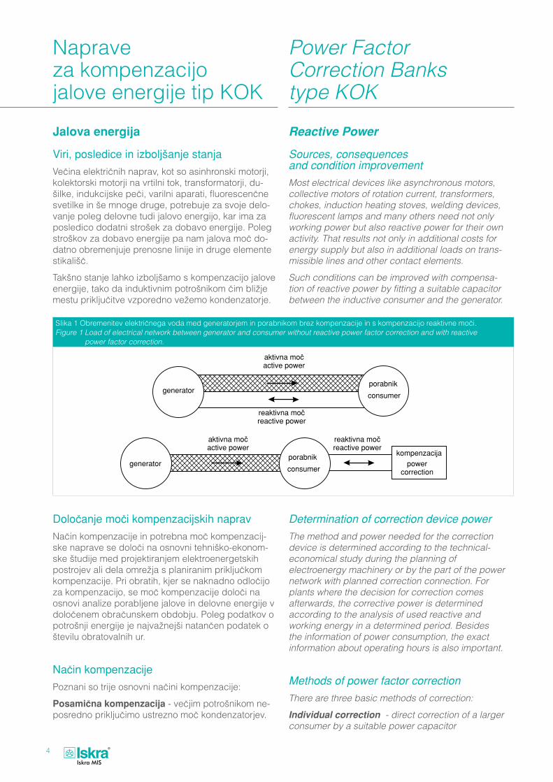
VeËina elektriËnih naprav, kot so asinhronski motorji, kolektorski motorji na vrtilni tok, transformatorji, du-šilke, indukcijske peËi, varilni aparati, fluorescenËne svetilke in še mnoge druge, potrebuje za svoje delo-vanje poleg delovne tudi jalovo energijo, kar ima za posledico dodatni strošek za dobavo energije. Poleg stroškov za dobavo energije pa nam jalova moË do-datno obremenjuje prenosne linije in druge elemente stikališË.
Takšno stanje lahko izboljšamo s kompenzacijo jalove energije, tako da induktivnim potrošnikom Ëim bližje mestu prikljuËitve vzporedno vežemo kondenzatorje.
DoloËanje moËi kompenzacijskih naprav
NaËin kompenzacije in potrebna moË kompenzacij-ske naprave se doloËi na osnovni tehniško-ekonom-ske študije med projektiranjem elektroenergetskih postrojev ali dela omrežja s planiranim prikljuËkom kompenzacije. Pri obratih, kjer se naknadno odloËijo za kompenzacijo, se moË kompenzacije doloËi na osnovi analize porabljene jalove in delovne energije v doloËenem obraËunskem obdobju. Poleg podatkov o potrošnji energije je najvažnejši natanËen podatek o številu obratovalnih ur.
NaËin kompenzacije
Poznani so trije osnovni naËini kompenzacije:
PosamiËna kompenzacija - veËjim potrošnikom ne-posredno prikljuËimo ustrezno moË kondenzatorjev.
Reactive Power
Sources, consequences and condition improvement
Most electrical devices like asynchronous motors, collective motors of rotation current, transformers, chokes, induction heating stoves, welding devices, fluorescent lamps and many others need not only working power but also reactive power for their own activity. That results not only in additional costs for energy supply but also in additional loads on trans-missible lines and other contact elements.
Such conditions can be improved with compensa-tion of reactive power by fitting a suitable capacitor between the inductive consumer and the generator.
Determination of correction device power
The method and power needed for the correction device is determined according to the technical- economical study during the planning of electroenergy machinery or by the part of the power network with planned correction connection. For plants where the decision for correction comes afterwards, the corrective power is determined according to the analysis of used reactive and working energy in a determined period. Besides the information of power consumption, the exact information about operating hours is also important.
Methods of power factor correction
There are three basic methods of correction:
Individual correction - direct correction of a larger consumer by a suitable power capacitor
SIika 1 Obremenitev elektriËnega voda med generatorjem in porabnikom brez kompenzacije in s kompenzacijo reaktivne moËi.Figure 1 Load of electrical network between generator and consumer without reactive power factor correction and with reactive
power factor correction.

5
Skupinska kompenzacija - skupini potrošnikov pri-kljuËimo ustrezno moË kondenzatorjev.
Centralna kompenzacija - s centralnega mesta roËno ali avtomatsko vkljuËujemo potrebno moË kon-denzatorjev.
Potrebno moË kompenzacije izraËunamo:
Av + An
Qc = ———— · (tg ϕ1 - tg ϕ2) T
Wv + Wn
tg ϕ1 = ————
Av + An
Qc = potrebna moË kompenzacijske naprave
Av = delovna energija - višja tarifa
An = delovna energija - nižja tarifa
Wv = jalova energija - višja tarifa
Wn = jalova energija - nižja tarifa
T = število obratovalnih ur v obraËunskem obdobju
tg ϕ2 = tg ϕ želenega cos ϕ2 (po tabeli 1)
Group correction - correction of a group of consumers by a suitable number of power capacitors
Central correction - manually or automatically switching on an adequate number of power capacitors from a central location.
Calculation of required corrective power:
Av + An
Qc = ———— · (tg ϕ1 - tg ϕ2) T
Wv + Wn
tg ϕ1 = ————
Av + An
Qc = required capacitor rating
Av = true energy - higher tariff
An = true energy - lower tariff
Wv = reactive energy - higher tariff
Wn = reactive energy - lower tariff
T = monthly operating hours
tg ϕ2 = tg ϕ required cos ϕ2 (according to Table 1)
SIika 2 PrikljuËek in delovanje posamiËne in centralne kompenzacije. Figure 2 Connection and operation of individual and central correction
cos ϕ tg ϕ sin ϕ cos ϕ tg ϕ sin ϕ cos ϕ tg ϕ sin ϕ cos ϕ tg ϕ sin ϕ
1 0 0 0.87 0.567 0.493 0.74 0.909 0.673 0.61 1,299 0.792
0.99 0.142 0.141 0.86 0.593 0.51 0.73 0.936 0.683 0.6 1,333 0.8
0.98 0.203 0.199 0.85 0.62 0.527 0.72 0.964 0.694 0.59 1,368 0.807
0.97 0.251 0.243 0.84 0.646 0.543 0.71 0.992 0.704 0.58 1,405 0.815
0.96 0.292 0.28 0.83 0.672 0.558 0.7 1,020 0.714 0.57 1,441 0.822
0.95 0.329 0.312 0.82 0.698 0.572 0.69 1,049 0.724 0.56 1,479 0.828
0.94 0.363 0.341 0.81 0.724 0.586 0.68 1,078 0.733 0.55 1,518 0.835
0.93 0.395 0.368 0.8 0.75 0.6 0.67 1,108 0.742 0.54 1,559 0.842
0.92 0.426 0.392 0.79 0.776 0.613 0.66 1,138 0.751 0.53 1,600 0.848
0.91 0.456 0.415 0.78 0.802 0.626 0.65 1,169 0.76 0.52 1,643 0.854
0.9 0.484 0.436 0.77 0.829 0.638 0.64 1,201 0.768 0.51 1,687 0.86
0.89 0.512 0.456 0.76 0.855 0.65 0.63 1,233 0.777 0.5 1,732 0.866
0.88 0.54 0.475 0.75 0.882 0.661 0.62 1,265 0.785
Tabela 1/Table 1

6
ObstojeËi fak-tor moËi cos ϕ1Existing power factor cos ϕ1
Želeni faktor moËi cos ϕ2 Required power factor cos ϕ2
0,7 0,75 0,8 0,82 0,84 0,86 0,88 0,9 0,92 0,94 0,95 0,96 0,98 1
0,2 3,88 4,02 4,15 4,20 4,25 4,31 4,36 4,41 4,47 4,54 4,58 4,61 4,70 4,90
0,25 2,85 2,99 3,12 3,17 3,23 3,28 3,33 3,39 3,45 3,51 3,54 3,58 3,67 3,87
0,3 2,16 2,30 2,43 2,48 2,53 2,59 2,64 2,70 2,75 2,82 2,85 2,89 2,98 3,18
0,35 1,66 1,79 1,93 1,98 2,03 2,08 2,14 2,19 2,25 2,31 2,34 2,38 2,47 2,68
0,4 1,27 1,41 1,54 1,59 1,65 1,70 1,75 1,81 1,87 1,93 1,96 2,00 2,09 2,29
0,45 0,96 1,10 1,23 1,29 1,34 1,39 1,44 1,50 1,56 1,62 1,65 1,69 1,78 1,98
0,5 0,71 0,85 0,98 1,03 1,09 1,14 1,19 1,25 1,31 1,37 1,40 1,44 1,53 1,73
0,52 0,62 0,76 0,89 0,94 1,00 1,05 1,10 1,16 1,22 1,28 1,31 1,35 1,44 1,64
0,54 0,54 0,68 0,81 0,86 0,91 0,97 1,02 1,07 1,13 1,20 1,23 1,27 1,36 1,56
0,56 0,46 0,60 0,73 0,78 0,83 0,89 0,94 1,00 1,05 1,12 1,15 1,19 1,28 1,48
0,58 0,38 0,52 0,65 0,71 0,76 0,81 0,86 0,92 0,98 1,04 1,07 1,11 1,20 1,40
0,6 0,31 0,45 0,58 0,64 0,69 0,74 0,79 0,85 0,91 0,97 1,00 1,04 1,13 1,33
0,62 0,25 0,38 0,52 0,57 0,62 0,67 0,73 0,78 0,84 0,90 0,93 0,97 1,06 1,27
0,64 0,18 0,32 0,45 0,50 0,55 0,61 0,66 0,72 0,77 0,84 0,87 0,91 1,00 1,20
0,66 0,12 0,26 0,39 0,44 0,49 0,54 0,60 0,65 0,71 0,78 0,81 0,85 0,94 1,14
0,68 0,06 0,20 0,33 0,38 0,43 0,48 0,54 0,59 0,65 0,72 0,75 0,79 0,88 1,08
0,7 0,14 0,27 0,32 0,37 0,43 0,48 0,54 0,59 0,66 0,69 0,73 0,82 1,02
0,72 0,08 0,21 0,27 0,32 0,37 0,42 0,48 0,54 0,60 0,63 0,67 0,76 0,96
0,74 0,03 0,16 0,21 0,26 0,32 0,37 0,42 0,48 0,55 0,58 0,62 0,71 0,91
0,76 0,11 0,16 0,21 0,26 0,32 0,37 0,43 0,49 0,53 0,56 0,65 0,86
0,78 0,05 0,10 0,16 0,21 0,26 0,32 0,38 0,44 0,47 0,51 0,60 0,80
0,8 0,05 0,10 0,16 0,21 0,27 0,32 0,39 0,42 0,46 0,55 0,75
0,82 0,05 0,10 0,16 0,21 0,27 0,34 0,36 0,41 0,49 0,70
0,84 0,05 0,11 0,16 0,22 0,28 0,31 0,35 0,44 0,65
0,86 0,05 0,11 0,17 0,23 0,26 0,30 0,39 0,59
0,88 0,06 0,11 0,18 0,21 0,25 0,34 0,54
0,9 0,06 0,12 0,15 0,19 0,28 0,48
0,92 0,06 0,09 0,13 0,22 0,43
0,94 0,03 0,07 0,16 0,36
Tabela 2: Faktor K1 (tg ϕ1 - tg ϕ2) /Table 2 : Factor K1 (tg ϕ1 - tg ϕ2)
Primer 1
MeseËna potrošnja elektriËne energije (iz obraËuna)
Av = 50.000 kWh
An = 40.000 kWh
Wv = 45.000 kWh
Wn = 43.000 kWh
T = 250
želeni cos ϕ = 0.95
Av + An Qc = ———— · (tg ϕ1 - tg ϕ2) = T
Example 1
Monthly consumption of electrical energy
Av = 50.000 kWh
An = 40.000 kWh
Wv = 45.000 kWh
Wn = 43.000 kWh
T = 250
required cos ϕ = 0.95
Av + An Qc = ———— · (tg ϕ1 - tg ϕ2) = T

7
50.000 + 40.000 Qc = ———————— · (0,977 - 0,329) = 250
= 360 · 0,648 = 233 kvar
Wv + Wn 45.000 + 43.000 tgϕ1 = ———— = ————————— 0,977
Av + An 50.000 + 40.000
cos ϕ1 = 0,71
želeni cos ϕ2 = 0,95 iz tabele 1 tg ϕ2 = 0,329
Tip in moË naprave izberemo iz tabel. Pri izbiri priporoËamo 20 - 30 % rezerve, zato v našem primeru izberemo kompenzacijsko napravo tip KOK7116 300 kvar.
Primer 2
Instalirano aktivno moË P = 100 kW s faktorjem moËi pred kompenzacijo cos ϕ1 = 0,74 želimo izboljšati na cos ϕ2 = 0,95.
V tabeli 2 v preseËišËu cos ϕ1 = 0,74 in cos ϕ2 = 0,95 najdemo faktor K1 = 0,58. Faktor K1 pomnožimo z aktivno moËjo:
Qc = P · K1 = 100 · 0,58 = 58 kvar
Tokovna razbremenitev s kompenzacijo
Z vgradnjo kompenzacijskih naprav razbremenimo transformatorje, kable in ostale elemente energetske-ga postroja ter s tem omogoËimo prikljuËitev novih potrošnikov.
V tabeli 3 najdemo faktor K2, s katerim pomnožimo tok pred kompenzacijo I1 pri cos ϕ1 na cos ϕ2 po kompenzaciji.
Primer 3
RaËunamo tokovno razbremenitev iz primera 2.
Aktivna moË P = 100 kW
Faktor moËi pred kompenzacijo cos ϕ1 = 0,74
Faktor moËi po kompenzaciji cos ϕ2 = 0,95
Faktor iz tabele 3 K2 = 0,78
Tok I1 pred kompenzacijo:
P 100 · 103 I1 = ——————— = ——————— = 195 A
√3 · U · cos ϕ1 √3 · 400 · 0,74
Tok I2 po kompenzaciji:
I2 = I1 · K2 = 195 · 0,78 = 152 A
Tokovna razbremenitev:
IR = I1 - I2 = 195 - 152 = 43 A
50.000 + 40.000 Qc = ———————— · (0,977 - 329) = 250
= 360 · 0,648 = 233 kvar
Wv + Wn 45.000 + 43.000 tgϕ1 = ———— = ———————— 0,977
Av + An 50.000 + 40.000
cos ϕ1 = 0,71
required cos ϕ2 = 0,95 from Table 1 tg ϕ2 = 0,329
Type and power of device are chosen from the table. A reserve of 20 - 30 % is recommended when choosing the correction bank. Considering this, we need to choose KOK7116 300 kvar.
Example 2
For installed active power P = 100 kW we want to im-prove the power factor cos ϕ1 = 0,74 to power factor cos ϕ2 = 0,95.
We should find the point of intersection between existing cos ϕ1 = 0,74 and required cos ϕ2 = 0,95 on Table 2. The value of factor K1 = 0,58. That factor (K1) should be multiplied with the value of active power:
Qc = P · K1 = 100 · 0,58 = 58 kvar
Current discharge with PF correction
With power factor correction we reach current dis-charging of transformers, cables and other elements of energy plants. This allows the connection of new consumers.
Factor K2 from Table 3 must be multiplied with the current before correction I1 at cos ϕ1 to cos ϕ2 after correction.
Example 3
Calculation of current discharging for Example 2.
Active power P = 100 kW
Power factor before correction cos ϕ1 = 0,74
Power factor after correction cos ϕ2 = 0,95
Factor K2 = 0,78 from Table 3
Current I1 before correction:
P 100 · 103 I1 = ——————— = ——————— = 195 A
√3 · U · cos ϕ1 √3 · 400 · 0,74
Current I2 after correction:
I2 = I1 · K2 = 195 · 0,78 = 152 A
Current discharging is:
IR = I1 - I2 = 195 - 152 = 43 A

8
ObstojeËi faktor moËi cos ϕ1
Existing power factor cos ϕ1
Želeni faktor moËi cos ϕ2 Required power factor cos ϕ2
0,7 0,75 0,8 0,85 0,90 0,95 1
0,2 0,29 0,27 0,25 0,24 0,22 0,21 0,20
0,25 0,36 0,33 0,31 0,29 0,28 0,26 0,25
0,3 0,43 0,40 0,38 0,35 0,33 0,32 0,30
0,35 0,50 0,47 0,44 0,41 0,39 0,37 0,35
0,4 0,57 0,53 0,50 0,47 0,44 0,42 0,40
0,45 0,64 0,60 0,56 0,53 0,50 0,47 0,45
0,5 0,71 0,67 0,63 0,59 0,56 0,53 0,50
0,55 0,79 0,73 0,69 0,65 0,61 0,58 0,55
0,6 0,86 0,80 0,75 0,71 0,67 0,63 0,60
0,65 0,93 0,87 0,81 0,76 0,72 0,68 0,65
0,7 1 0,93 0,88 0,82 0,78 0,74 0,70
0,75 1 0,94 0,88 0,83 0,79 0,75
0,8 1 0,94 0,89 0,84 0,80
0,85 1 0,94 0,89 0,85
0,9 1 0,95 0,90
0,95 1 0,95
Tabela 3: faktor K2 (cos ϕ1/cos ϕ2) /Table 3: Factor K2 (cos ϕ1/cos ϕ2)
PosamiËna kompenzacija PosamiËna kompenzacija je obiËajno izvedena s stal-nimi kondenzatorji ali napravami. Tako kompenziramo motorje in transformatorje.
PosamiËna kompenzacija nizkonapetostnih motorjev
Nizkonapetostne motorje, ki so redko preklapljani, je iz tehniËnih in stroškovnih razlogov primerno kompen-zirati s stalno prikljuËenim kondenzatorjem.
Pri tem je potrebno upoštevati predvsem naslednje:
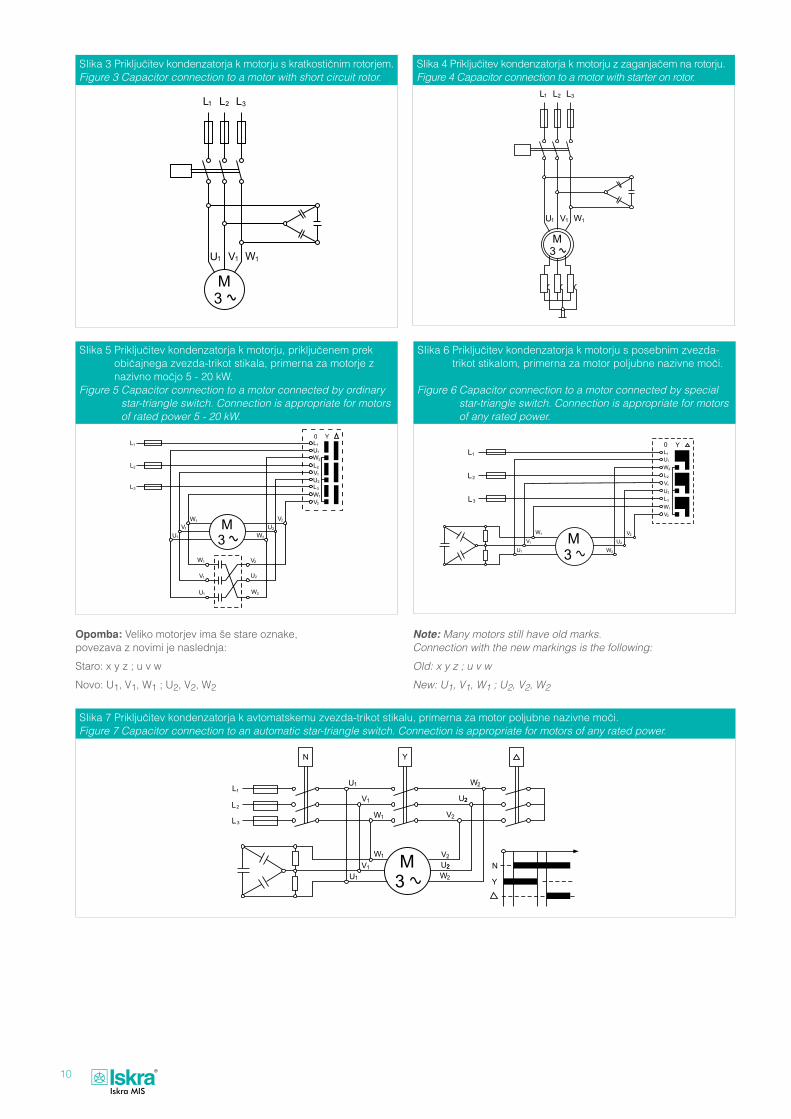
1. »e je motor vklopljen s stikalom zvezda-trikot, je potrebno pri uporabi trifaznega kondenzatorja, veza-nega v trikot, uporabiti posebno stikalo, da pri pre-klopu ne pride do škodljivih prenapetosti in tokovnih sunkov. »e tako stikalo ni na razpolago, je potrebno uporabiti kondenzator s 6 poli, ki jih prikljuËimo para-lelno k navitjem motorja.
NaËini prikljuËevanja kondenzatorja so prikazani na slikah 3, 4, 5, 6 in 7.
2. Poraba reaktivne moËi motorja je odvisna od tipa motorja, posebno pa še od števila obratov in stopnje obremenitve. Izbor pravilne vrednosti kondenzatorja mora poleg upoštevanja teh podatkov upoštevati tudi možnost hitre razbremenitve motorja.
Individual CorrectionIndividual power factor correction is normally achieved with fixed capacitors or devices. It is particularly suitable for individual power factor correction of motors and transformers.
Individual Power Factor Correction for Low Voltage Motors
It is useful to compensate rarely switched low volt-age motors with a fixed connected capacitor due to technical and cost reasons.
1. If motors are connected with a star-triangle switch, there needs to be a special switch used to connect a three-phase capacitor. Otherwise it can suffer harmful overstrains and current shocks. If such a switch is not available, a capacitor with 6 poles needs to be used. These poles must be connected parallel to the motor winding.
Ways of connection are shown in pictures 3, 4, 5, 6 and 7.
2. Use of the motor's reactive power depends on the motor type and especially on the speed of rotation and load level. Also the ability of the motor to dis-charge quickly must be considered when choosing the right type of capacitor.
If such a possibility exists, the motor can be corrected for only up to 90 % of the reactive energy used at no load.

9
Nazivna moË motorja
Rated motor power(kW)
MoËi kondenzatorjev v (kvar) glede na moË motorjev, število obratov in obremenitev Power rating of capacitor in (kvar) with respect to motor power, speed of rotation and load
3000 rev/min 1500 rev/min 1000 rev/min 750 rev/min 500 rev/min
prazni tek
no load
polna obremenitev
full load
prazni tek
no load
polna obremenitev
full load
prazni tek
no load
polna obremenitev
full load
prazni tek
no load
polna obremenitev
full load
prazni tek
no load
polna obremenitev
full load
5,5 2,2 2,9 2,4 3,3 2,7 3,6 3,2 4,3 4 5,2
7,5 3,4 4,4 3,6 4,8 4,1 5,4 4,6 6,1 5,5 7,2
11 5 6,5 5,5 7,2 6 8 7 9 7,5 10
15 6,5 8,5 7 9,5 8 10 9 12 10 13
18,5 8 11 9 12 10 13 11 15 12 16
22 10 12,5 11 13,5 12 15 13 16 15 19
30 14 18 15 20 17 22 22 25 22 28
37 18 24 20 27 22 30 26 34 29 39
45 19 28 21 31 24 34 28 38 31 43
55 22 34 25 37 28 41 32 46 36 52
75 28 45 32 49 37 54 41 60 45 68
90 34 54 39 59 44 65 49 72 54 83
110 40 64 46 70 52 76 58 85 63 98
132 45 72 53 80 60 87 67 97 75 110
160 54 86 64 96 72 103 81 116 91 132
200 66 103 77 115 87 125 97 140 110 160
250 75 115 85 125 95 137 105 150 120 175
Tabela 4/Table4
»e taka možnost obstaja, je obiËajno možno motor kompenzirati samo do 90-odstotne porabe reaktivne moËi v praznem teku po enaËbi:
Qc = 0,9 · Un · Im · √3,
kjer je:
Qc - moË kondenzatorja (var)
Un - nazivna napetost (V)
Im - magnetilni tok (A)
Pri veËjem kondenzatorju lahko pri hitri razbremenitvi motorja pride do lastnega vzbujanja. »e hitra razbre-menitev motorja ni možna, se motor lahko kompenzira glede na dejansko porabo reaktivne moËi.
Orientacijske vrednosti so podane v tabeli 4.
The required capacitor power is calculated with the following formula:
Qc = 0,9 · Un · Im · √3,
where:
Qc - capacitor power (var)
Un - rated voltage (V)
Im - motor magnetising current (A)
Quick discharging with a bigger capacitor can cause self-excitation. If quick discharging of the motor is not possible, the motor can compensate itself according to the actual consumption of reactive power.
Orientational values are found in Table 4.
10
SIika 3 PrikljuËitev kondenzatorja k motorju s kratkostiËnim rotorjem.Figure 3 Capacitor connection to a motor with short circuit rotor.
SIika 7 PrikljuËitev kondenzatorja k avtomatskemu zvezda-trikot stikalu, primerna za motor poljubne nazivne moËi. Figure 7 Capacitor connection to an automatic star-triangle switch. Connection is appropriate for motors of any rated power.
SIika 5 PrikljuËitev kondenzatorja k motorju, prikljuËenem prek obiËajnega zvezda-trikot stikala, primerna za motorje z nazivno moËjo 5 - 20 kW.
Figure 5 Capacitor connection to a motor connected by ordinary star-triangle switch. Connection is appropriate for motors of rated power 5 - 20 kW.
SIika 6 PrikljuËitev kondenzatorja k motorju s posebnim zvezda-trikot stikalom, primerna za motor poljubne nazivne moËi.
Figure 6 Capacitor connection to a motor connected by special star-triangle switch. Connection is appropriate for motors of any rated power.
SIika 4 PrikljuËitev kondenzatorja k motorju z zaganjaËem na rotorju.Figure 4 Capacitor connection to a motor with starter on rotor.
Opomba: Veliko motorjev ima še stare oznake, povezava z novimi je naslednja:
Staro: x y z ; u v w
Novo: U1, V1, W1 ; U2, V2, W2
Note: Many motors still have old marks. Connection with the new markings is the following:
Old: x y z ; u v w
New: U1, V1, W1 ; U2, V2, W2

11
Kompenzacija energetskih transformatorjev Podobno kot motorje je tudi energetske transformator-je pogosto praktiËno kompenzirati s stalno prikljuËeni-mi kondenzatorji.
Reaktivna moË transformatorja se sestoji iz moËi v praznem teku Q0 in moËi na reaktanci kratkega stika po enaËbi: Uk S Qtr = Q0 + ——— (—)2 S, kjer je: 100% Sn
S = navidezna moË
Sn = nazivna navidezna moË
Uk = relativna napetost kratkega stika
Reaktivna moË v praznem teku Q0 je od 1 % do 3,5 % nazivne moËi transformatorja, za orientacijo služijo podatki na sl. 9 in v tabeli 5.
Skupna potrebna moË za kompenzacijo v distribucij-skih transformatorjih je 4 % do 5 % nazivne moËi, pri povpreËni obremenitvi 70 %.
Neposredna kompenzacija samo lastne porabe trans-formatorja se redko izplaËa. V takem primeru je kon-denzator fiksno prikljuËen na sekundar transformator-ja. MoË kondenzatorja je izbrana tako, da kompenzira polno obremenjeni transformator. Za orientacijo se uporabijo vrednosti, navedene v tabeli 5. Pogosto pa
Power Factor Correction for Power TransformersLike motors, power transformers can also often be practically corrected by fixed connected capacitors.
Transformer reactive power consists of no load power Q0 and of power on the short-circuit reactance according to the following formula: Uk S Qtr = Q0 + ——— (—)2 S, where: 100% Sn
S = apparent power
Sn = rated apparent power
Uk = relative voltage of short circuit
No load reactive power Q0 is from 1 % to 3,5 % of rated transformer power. See figure 9 and table 5 for orientation data.
The total correction power required in distribution transformers is 4 % to 5 % of rated power at an average load of 70 %.
Direct correction on only self-use transformers is rarely useful. In that case the capacitor has a fixed connection to a secondary transformer. The power of the capacitor is chosen to compensate the full load of the transformer. Data from Table 5 are used for orientation. Usually the fixed capacitor is also chosen
Nazivna moË transformatorjaRated power of transformer
(kVA)
MoËi kondenzatorjev v (kvar) glede na primerno napetost in obremenitevPower ratings of capacitor in (kvar) with respect to primary voltage and load
5 to 10 kV 15 to 20 kV 25 to 30 kV
prazni tekno load
polna obremenitevfull load
prazni tekno load
polna obremenitevfull load
prazni tekno load
polna obremenitevfull load
5 0,75 1 0,8 1,1 1 1,3
10 1,2 1,7 1,5 2 1,7 2,2
20 2 3 2,5 3,5 3 4
25 2,5 3,5 3 4 4 5
75 5 8 6 9 7 11
100 6 10 8 11 10 13
160 10 12 12 15 15 18
200 11 17 14 19 18 22
250 15 20 18 22 20 25
315 18 25 20 28 24 32
400 20 30 22 36 28 40
500 22 40 25 45 30 50
630 28 46 32 52 40 61
1000 45 80 50 85 55 95
1250 50 85 55 90 60 100
1600 70 100 60 110 70 120
2000 80 160 85 170 90 180
5000 150 180 170 200 200 250
Tabela 5/Table 5

12
se fiksni kondenzator izbere tako, da so kompenzirani tudi mreža in majhni, sicer nekompenzirani potrošniki.
V takem primeru je potrebno upoštevati naslednje: • poveËanje napetosti v praznem teku zaradi pre-
kompenzacije
Qc
ΔU(%) = Uk(%) —— , kjer je: Sn
Qc - moË kondenzatorja
Sn - nazivna moË transformatorja
To poveËanje je obiËajno zanemarljivo.
• možnost paralelne resonance 5. in 7. harmonika pri majhni obremenitvi transformatorja. Da do tega ne pride, moË prikljuËenega kondenzatorja ne sme biti veËja od vrednosti, navedenih na sl. 10, kjer je moË kondenzatorja podana v odstotkih nazivne moËi transformatorja. Kot praktiËna orientacija se na-vaja, da pri transformatorju moËi do 300 kVA moË kondenzatorja lahko znaša do 30 % moËi transfor-matorja.
NaËin prikljuËevanja kondenzatorja je prikazan na sliki 8.
to compensate for the power network and small uncorrected consumers.
In that case the following need to be considered: • no load voltage is increasing because
of overcorrection
Qc
ΔU(%) = Uk(%) —— , where: Sn
Qc - capacitor power
Sn - rated power of transformer
This increase is usually negligible.
• The possibility of parallel resonance of the 5th and 7th harmonics in case of low transformer load. In order to prevent this from ocurring, the power of connected capacitator should not exceed values indicated in Figure 10, where the capacitator power is given in percentages of the rated power of the transformer. For purposes of practical orientation it is stated, that in case of transformer power of up to 300 kVA, the capacitor power can amount up to 30 % of the transformer power.
The manner of connecting the capacitator is indicated in Figure 8.
SIika 8 PrikljuËitev kondenzatorja k srednjenapetostnemu transformatorju.
Figure 8 The capacitor connection to medium-voltage transformers.
SIike 9 Reaktivna moË transformatorja v praznem teku, izražena v odstotkih nazivne moËi (minimalne vrednosti).
Figure 9 Proportion of transformer reactive power out of load ex-pressed in the percentage of rated power (minimal value).
SI.10 NajveËja dopustna moË kondenzatorja v praznem teku trans-formatorja, izražena v odstotkih nazivne moËi transformatorja.
Fig.10 Maximum allowed capacitor power at no load expressed in percentage of rated power transformers.

13
Stalne kompenzacijske naprave
Fixed Power Factor Correction Banks
Namen uporabe
Stalne kompenzacijske naprave so namenjene za kompenzacijo nizkonapetostnih transformatorjev, mogoËe pa jih je uporabiti tudi kot poveËanje moËi že vgrajene kompenzacijske naprave. PoveËanje je lahko stalno prikljuËeno, Ëe pa ima regulator naprave še proste stopnje, se ga da izvesti tudi kot del avto-matske naprave.
Konstrukcija
Naprave imajo kovinsko ohišje, primerno za stojeËo ali viseËo montažo. Kompenzacijski elementi so enofa-zni, lonËaste izvedbe. Vsak kondenzatorski element ima vgrajen mehanski odklopnik na nadpritisk in upor za praznjenje, izvedba je metalpolipropilenska in samoozdravljiva, brez PCB impregnanta. Naprava je zašËitena s talilnimi varovalkami, vklopni tokovi so na zahtevo omejeni z dušilkami.
Purpose of use
Fixed power factor correction banks are used for the correction of low voltage transformers. It can also be used to increase the power of already connected correction devices. The increase can be constantly connected, but if the reactive power factor controller still has free levels it could be performed as a part of an automatic device.
Construction
Banks have sheet steel case suitable for floor or wall mounting. Correction elements are one-phased in a cylindrical aluminous case. The case of each capaci-tor has an overpressure disconnector and discharge resistor. It consists of metallized polypropylene foil, is self-healing and not PCB impregnated. The device is protected by thermal cutout, inrush currents are limited by chokes, if so requested.
Tip KOK7411izvedba za notranjo mon-tažo s kondenzatorskimi elementi, vezanimi v trikot
Type KOK7411application for inner mounting with capacitors connected in a triangle
Tipsko izdelujemo: Applications:
TEHNI»NI PODATKI Nazivna moË: glej tabelo 6
Nazivna napetost: 400 V, 50 Hz trifazno, ostale napetosti na zahtevo
Toleranca kapacitivnosti:
od 0 % do + 10 %
Dopustne preobremenitve:
1,0 × Un trajno 1,1 × Un 8 ur dnevno 1,3 × In trajno
Temperaturni razred: od -25 °C do +50 °C
DielektriËne izgube: ≤ 0,2 W/kvar
Skupne izgube naprave: < 1,5 W/kvar
Stopnja zašËite po DIN 40050:
IP 32
Stopnja izolacije: skupina C po VDE 0110
ZašËita pred previsoko napetostjo dotika:
TN
Barva: RAL 7032
Naprave so izdelane v skladu z/s:
• IEC publikacijami 831-1, 831-2,
• EN 60831/1-2,• VDE predpisi 0110, 560-41,• tehniËnimi predpisi za
izvajanje elektroenergetskih instalacij v zgradbah
TECHNICAL DATARated power: see table 6
Rated voltage: 400 V, 50 Hz three-phase, other voltages on request
Capacity tolerance: from 0 % to + 10 %
Overload capacity: 1,0 × Un permanent 1,1 × Un 8 hours per day 1,3 × In permanent
Temperature range: od -25 °C do +50 °C
Dielectric losses: ≤ 0,2 W/kvar
Total losses of device: < 1,5 W/kvar
Level of protection according to DIN 40050:
IP 32
Level of isolation: group C according to VDE 0110
Protection against exces-sive voltage contact:
TN
Colour: RAL 7032
Complies with standard: • IEC Publ. 831-1, 831-2, • EN 60831/1-2,• VDE regulation 0110,
560-41, • technical regulations for
electrical installation in buildings

14
MoËPower(kvar)
Nazivni tokRated current
(A)
Nazivnakapacitivnost
Rated capacity
(μF)
SlikaFigure
dimensions(*)
Varovalke F1Safety fuse
(kvar)
Prikl. kabelConnecting
cablePP00...
mm² (Cu)
UvodnicaSleeve
TežaWeight
(kg)
10 14,4 3 × 66,3 11 25 4 × 6 PG 21 5,2
15 21,7 3 × 99,5 11 36 4 × 6 PG 21 6,8
20 28,9 3 × 132,6 11 50 4 × 16 PG 21 8,5
30 43,3 3 × 198,9 12 80 4 × 16 PG 29 11,0
40 57,7 3 × 265,2 12 100 3 × 25/16 PG 29 13,5
50 72,2 3 × 331,6 12 125 3 × 35/16 PG 36 15,0
60 86,6 3 × 397,8 12 125 3 × 50/25 PG 36 17,5
70 101,0 3 × 464,1 12(*) 160 3 × 70/35 PG 36 20,0
75 108,0 3 × 497,2 12(*) 160 3 × 70/35 PG 42 22,0
100 144,3 3 × 663,2 12(*) 200 3 × 95/35 PG 42 26,0
Tabela 6 Tip KOK7411 400 V 50 Hz/Table 6 Type KOK7411 400 V 50 Hz
Kabli so dimenzionirani za temperaturo okolice 30 °C. Cables are dimensioned for surrounding temperature 30 °C.
Dimenzijske skice za naprave KOK7411Dimension sketches for KOK7411
* Dimenzije za moË > 60 kvar* Dimensions for power > 60 kvar
PrikljuËna shema naprave KOK7411Connection scheme of type KOK7411

15
Naprave za avtomatsko kompenzacijo jalove energije
Automatic Power Factor Correction Banks
Skupinska in centralna kompenzacija sta obiËajno izvedeni z avtomatskimi napravami. VËasih je avto-matska naprava kombinirana s stalno napravo. To je ekonomsko smiselno pri porabnikih z veËjim številom stalno prikljuËenih veËjih motorjev.
Avtomatske kompenzacijske naprave
Namen uporabe
Naprave tip KOK so namenjene za skupinsko in centralno kompenzacijo reaktivne energije v elektro-razdelilnih postrojih, industrijskih in drugih proizvodnih obratih ter ustanovah. Izdelujemo jih v spektru od 17,5 kvar do 720 kvar.
Naprave tip KOK761x in 751x so naprave manjših moËi za notranjo montažo, namenjene za montažo v proizvodnih postrojih in ustanovah, kjer je poraba reaktivne moËi sorazmerno majhna, vendar se Ëasovno tako spreminja, da je potrebna vgradnja avtomatske naprave.
Naprave tip KOK711x so naprave veËjih moËi za no-tranjo montažo, namenjene za industrijske in razdelil-ne postroje.
Vse naprave so prirejene za kabelsko prikljuËevanje s spodnje strani. Na posebno zahtevo izdelujemo napra-ve za drugaËen naËin prikljuËevanja, za zunanjo mon-tažo in za montažo na omrežje z MTK signalom, kjer je potrebno vgraditi zaporne nihajne kroge za ohranjanje signala in druge izvedbe po zahtevah kupca.
Konstrukcija
Vse naprave KOK imajo naËelno enak princip kon-strukcije. Ohišje je kovinsko, v obliki ene ali veË omar, osnovna stopnja zašËite IP2O. Pri napravah KOK711x je vsak kabelski prikljuËek izveden na bakrene zbiral-nice. Vsaka naprava ima vgrajen avtomatski regulator reaktivne moËi za prikljuËek na eno fazo nizke napeto-sti, preklopni elementi so kontaktorji, skupine konden-zatorjev so varovane s talilnimi varovalkami, skupine kondenzatorjev v posameznih stopnjah so sestavljene iz enofaznih kondenzatorjev lonËaste oblike, vezanih v trikot. Kondenzatorji so metalpolipropilenski, sa-moozdravljivi, brez PCB impregnanta in opremljeni z mehansko zašËito varovalk na nadpritisk. V vseh napravah so vklopni tokovi v posameznih stopnjah omejevani.
Naprave KOK711x so modularne izvedbe. Kondenza-torji, kontaktorji in varovalke so vgrajeni v modul pre-dalËne oblike. MoË posameznega modula je (odvisno od števila stopenj) najveË 60 kvar.
Group and central correction are usually performed with automatic banks. Sometimes the automatic banks is combined with a fixed one. This is economically reasonable for consumers with more fixed connection big motors.
Automatic correction banks
Purpose of use
Devices type KOK are used for group and central correction of reacitve power in distribution centres, industrial and other production plants. They are made in a range of outputs from 17,5 kvar to 720 kvar.
Types KOK761x and 751x are banks of lower power for inner mounting. They are used in production plants where the consumption of reactive power is proportionally small but changes in time, so an automatic device is needed.
Types KOK711x are high power devices for inner mounting used for industrial and distribution centres.
All banks are customized for cable connection from the bottom. On special request banks for different types of connection or outside mounting can also be produced. Also, mounting on a power network with an MTK signal where it is required to install interlocking oscillator circuits in order to maintain the signal and other versions at the request of the customer.
Construction
In principle all KOK banks have the same method of construction. They are constructed in steel-plate cabinets (one or two) with a basic level of protection, IP2O. Each bank KOK711x has an automatic reactive power factor controller for one-phase connection in low voltage power networks. Switching elements are contacts. Capacitor groups are protected by burning out fuses. Capacitor groups in individual levels are composed of one-phase capacitors in cilindrical Al cases, which are triangularly connected. Capacitors are made of metallized polypropylene, are self-healing, not PCB impregnated and have an overpressure disconnector. In all banks the starting currents are restrictive in individual stages.
Types KOK711x are modularly operated. Capacitors, contacts and fuses are built into individual modules. The power of each module is (depending on the number of stages) a maximum of 60 kvar.

16
Naprave so sestavljene iz ene ali veË omar, v katere so vgrajeni gornji moduli, regulator je vgrajen samo v prvo omaro vsake naprave. Taka konstrukcija omo-goËa naknadno poveËanje moËi naprave z dodaja-njem modulov oziroma omar.
Pri napravah KOK761x je, na zahtevo kupca, možno poveËati število stopenj, do najveË šest.
The devices are made of one or more banks into which upper modules are fitted. The controller is put only in the first bank of each device. Such construction allows future upgrades to the power of the device by adding modules or banks.
On customer request it possible to increase the number of stages to a maximum of 6 for type KOK761x.
TEHNI»NI PODATKI ObmoËje moËi: glej tabelo; ostale moËi ali
kombinacije so možne na zahtevo
Nazivna napetost: 400 V, 50 Hz trifazno
Krmilna napetost: 231 V, 50 Hz
DinamiËna trdnost zbiralnic:
do 100 kA
TermiËni tok kratkega stika:
do 40 kA
Toleranca moËi: od 0 % do + 10 %
Dopustne preobremenitve:
1,0 × Un trajno 1,1 × Un 8 ur dnevno 1,3 × In trajno
Temperaturni razred: od -10 °C do +40 °C
DielektriËne izgube: ≤ 0,2 W/kvar
Skupne izgube naprave: < 1,5 W/kvar
Stopnja izolacije: skupina C po VDE 0110
Stopnja mehanske zašËite: IP 2O
ZašËita pred previsoko napetostjo dotika:
TN-C ali TN-S
Barva: RAL 7032, ali po naroËilu
Napajanje prek tokovnega transformatorja:
X / 5A
Poraba merilnega sistema: 15 VA
Naprave so izdelane in preizkušene v skladu z:
• IEC publikacijami 831-1, 831-2, 439,
• EN 60831/1-2
PRIMER ZA NARO»ILOTip: KOK7116
Nazivna moË: 250 kvar
Nazivna napetost: 400 V, 50 Hz, trifazno
Posebne zahteve: navesti odstopanja od tipske izvedbe
TECHNICAL DATAPower range: see table; other
powers or combinations on request
Rated voltage: 400 V, 50 Hz three-phase
Control voltage: 231 V, 50 Hz
Dynamic strength of collectors:
to 100 kA
Thermic current of short circuit:
to 40 kA
Power tolerance: from 0 % to + 10 %
Allowed overloading: 1,0 × Un permanent 1,1 × Un 8 hours per day 1,3 × In permanent
Temperature range: from -10 °C to +40 °C
Dielectric losses: ≤ 0,2 W/kvar
Total losses of device: < 1,5 W/kvar
Insulation level: group C according to VDE 0110
Level of mechanical pro-tection:
IP 2O
Protection against exces-sive voltage contact:
TN-C or TN-S
Colour: RAL 7032, or on request
Electric supply through current transformer:
X / 5A
Measured system consumption:
15 VA
Complies with: • IEC Publ. 831-1, 831-2, 439
• EN 60831/1-2
ORDER EXAMPLEType: KOK7116
Rated power: 250 kvar
Rated voltage: 400 V, 50 Hz, three-phase
Special requirements: Indicate deviations form the design type.
Na željo kupca nudimo inženiring, ki na osnovi po-datkov kupca izbere tip in moË naprave ter izvede prikljuËitev.
Projektiramo in izdelujemo kondenzatorske naprave posebnih izvedb na nizki napetosti.
On customer request we offer client-specific engineering, which will select the type and power of device according to customer information and perform the connection.
We work on and produce capacitor devices of different low-voltage applications.
Vsaka osnovna naprava se lahko razširi z vgradnjo dodatne omare brez regulatorja.
Every basic unit can be extended by adding extension cubicle without power factor control relay.

17
Podatki o napraviDevice information
Podatki za prikljuËevanjeConnection information
TipType
MoËPower range
(kvar)
Število in moË stopenjNumber and power
of stages (kvar)
Max. tokMax. current
(A)
TežaWeight
(kg)
PrikljuËne varovalkeConnection fuses
(A)
Dovodni kabliCable portsmm2 (Cu)
KOK7613 25 5 + 2 × 10 36 40 63 4 × 16
KOK7614 35 5 + 3 × 10 50,5 45 80 3 × 25 / 16
KOK7614 45 5 + 10 +15 + 15 65 50 100 3 × 35 / 16
KOK7614 60 10 + 10 + 20 + 20 86,7 70 160 3 × 50 / 25
KOK7614 80 10 + 10 + 20 + 20 + 20 116 80 160 3 × 70 / 35
KOK7614 90 10 + 20 + 30 + 30 130 82 200 3 × 95 / 50
KOK7614 105 15 + 3 × 30 152 90 250 2 × 3 × 50 / 25
KOK7615 120 15 + 15 + 3 × 30 173 95 315 2 × 3 × 70 / 35
KOK7615 135 15 + 4 × 30 195 100 315 2 × 3 × 70 / 35
Podatki o napraviDevice information
Podatki za prikljuËevanjeConnection information
TipType
MoËPower range
(kvar)
Število in moË stopenjNumber and power of stages
(kvar)
Max. tokMax. current
(A)
TežaWeight
(kg)
PrikljuËne varovalkeConnection fuses
(A)
Dovodni kabliCable portsmm2 (Cu)
KOK7513 17,5 2,5 + 5 + 10 25 27 40 4 × 16
KOK7513 25 5 + 2 × 10 36 29 63 4 × 16
KOK7514 35 5 + 3 × 10 50,5 32 80 3 × 25 / 16
KOK7514 45 5 + 10 + 15 + 15 65 34 100 3 × 35 / 16
KOK7514 52,5 7,5 + 3 × 15 76 35 125 3 × 50 / 25
Tabela 7: Tip KOK761x 400 V 50 Hz - trifazno - STENSKA IZVEDBA - ZIDNA MONTAŽATable 7: Type KOK761x 400 V 50 Hz - three-phase - WALL MOUNTING
Tabela 8: Tip KOK751x 400 V 50 Hz - trifazno - STENSKA IZVEDBA - ZIDNA MONTAŽATable 8: Type KOK751x 400 V 50 Hz - three-phase - WALL MOUNTING
Kabli so dimenzionirani za temperaturo okolice 30 °C. Cables are dimensioned for surrounding temperature 30 °C.
Dimenzijska skica naprave KOK761xDimension sketch for KOK761x
Dimenzijska skica naprave KOK751xDimension sketch for KOK751x

18
Dimenzijska skica naprave KOK711xDimension sketch for KOK711x
Kabli so dimenzionirani za temperaturo okolice 30 °C. Cables are dimensioned for surrounding temperature 30 °C.
Podatki o napraviDevice information
Podatki za prikljuËevanjeConnection information
TipType
MoËNominal power(kvar)
Število in moË stopenjNumber and
power of stages(kvar)
Max. tokMax. current
(A)
TežaWeight
approximate(kg)
PrikljuËne varovalke
Connection fuses gl(A)
Dovodni kabliSupply cable cross section
mm2 (Cu)
KOK7115 100 12,5+12,5+3x25 144 140 250 3x95/50
KOK7114 100 4x25 144 140 250 3x95/50
KOK7116 125 12,5+12,5+4x25 180 144 250 3x120/70
KOK7115 125 5x25 180 144 250 3x120/70
KOK7117 150 12,5+12,5+5x25 217 167 315 3x185/95
KOK7116 150 6x25 217 165 315 3x185/95
KOK7118 175 12,5+12,5+6x25 253 177 400 2x3x95/70
KOK7117 175 7x25 253 175 400 2x3x95/70
KOK7114 175 25+3x50 253 173 400 2x3x95/70
KOK7119 200 12,5+12,5+7x25 289 210 400 2x3x95/70
KOK7118 200 8x25 289 200 400 2x3x95/70
KOK7115 200 25+25+3x50 289 198 400 2x3x95/70
KOK7110 225 12,5+12,5+8x25 325 220 500 2x3x120/70
KOK7117 225 7x25 325 218 500 2x3x120/70
KOK7115 225 25+4x50 325 215 500 2x3x120/70
KOK7111 250 12,5+12,5+9x25 361 230 500 2x3x120/70
KOK7110 250 10x25 361 230 500 2x3x120/70
KOK7116 250 25+25+4x50 361 230 500 2x3x12070
KOK7112 300 12x25 433 245 630 2x3x185/95
KOK7117 300 2x25+5x50 433 240 630 2x3x185/95
KOK7116 300 6x50 433 235 630 2x3x185/95
Tabela 9: Tip KOK71xx 400 V 50 Hz - trifaznoTable 9: Type KOK71xx 400 V 50 Hz - three-phase

19
Naprave za avtomatsko kompenzacijo jalove energije s filtriranjem višjih harmonikov
Automatic Power Factor Correction Banks with Harmonics Filters
Namen uporabe
Naprave za avtomatsko kompenzacijo jalove energije s filtriranjem višjih harmonikov tip KOK811x so namenje-ne za centralno kompenzacijo jalove energije v elektro-energetskih sistemih, industrijskih in drugih proizvodnih obratih tam, kjer so prisotni višji harmoniki v omrežju.
ObiËajno se filtrira 5. harmonik, ki je v omrežju naj-pogosteje najbolj intenziven. Možno je tudi pasovno filtriranje posameznih harmonikov, in sicer 5., 7. in 11.
Konstrukcija
Naprava je v obliki kovinske omare z vrati, lakirana z barvo, oznake RAL7032, opremljena z ventilatorjem in zraËnikom za zraËenje, ter s transportnimi vijaki. Naprave so modularne izvedbe. Vsak modul, ki je narejen iz galvansko zašËitene ploËevine, vsebuje kondenzatorje za kompenzacijo jalove energije tip KNK5015, kontaktorje s hitropraznilnimi upori, tripolne varovalke, velikosti NH 00 s talilno karakteristiko gL, zbiralke, sponke za ožiËenje in dušilke za filtriranje višjih harmonikov za resonanËne frekvence:
fr = 189 Hz p = 7 %
fr = 213 Hz p = 5,5 %
Na vratih naprave je vgrajen regulator jalove moËi tip KRK. Število stopenj regulatorja je 6 ali 12, odvisno od tipa naprave.
Naprave nimajo vgrajenih glavnih stikal. Hitra loËitev kondenzatorskih enot od omrežja je možna z grebe-nastim stikalom na vratih naprave.
MoËi naprav
Osnovni spekter moËi naprav je od 150 kvar do 720 kvar (glej tabelo 10). Maksimalna moË ene omare z glavnim stikalom je 240 kvar ali 300 kvar za omaro brez glavnega stikala. Nadaljno poveËanje moËi je možno z enostavnim dodajanjem ene ali dveh omar. V tem primeru je regulator jalove moËi namešËen samo na prvi omari, krmili pa celo napravo. Na zahtevo so možne tudi drugaËne kombinacije moËi stopenj.
PrikljuËek
Kabelski prikljuËek se nahaja na spodnji strani napra-ve. Za prikljuËek naprave je dovolj prikljuËiti napajalne kable in vodnike za signal s tokovnega transformatorja.
Purpose of use
Banks for automatic correction of reactive power by filtering higher harmonics type KOK811x are used for central correction of reactive power in electropower systems, industrial and other plants where higher harmonics are present in the power network.
Usually the fifth harmonic is filtered, as it is usually the strongest one. It is also possible to filter individual harmonics 5, 7 and 11.
Construction
It is a metal bank with a door, painted in the colour RAL7032, equipped with ventilation and transport screws. The banks are modularly made. Each mod-ule made of galvanic protected sheet metal consists of capacitors for reactive power correction type KNK5015, connectors with quick discharge resistors, tripole fuses dimensions NH 00 with gL melting char-acteristics, collectors, chips for wiring, and chokes for filtering higher harmonics for resonance frequency.
fr = 189 Hz p = 7 %
fr = 213 Hz p = 5,5 %
There is a reactive power regulator, type KRK, mount-ed on the front door. The number of stages of the regulator is 6 or 12, depending on the type of device.
These banks do not have a main switch. Quick dis-connection of the capacitor from the power network is possible with the switch on the front door.
Device power
The basic power spectrum is from 150 kvar to 720 kvar (see table 10). Maximum power of one bank with the main switch is 240 kvar and 300 kvar for the bank without the switch. Additional increases of power are possible by adding one or two banks. In such case the reactive power regulator is mounted only in the first bank, but it controls the whole device. On request it is possible to also produce other combinations of power stages.
Connector
The cable connection is at the bottom of the bank. For bank connection it is enough to connect cable ports and wires for signal from circuit transformer.

20
Dimenzije
Dimenzije ene omare so 800 × 2100 × 600 mm. V tehniËnih podatkih so podane dimenzije naprav za razliËne moËi.
Dimensions
Dimensions of one bank are 800 × 2100 × 600 mm. Dimensions of devices for different powers are in-cluded in technical data.
TEHNI»NI PODATKI Tip naprave: KOK81xx, 82xx
Nazivna moË Pn: glej tabelo 10
Število in moË stopenj: glej tabelo 10
Nazivna napetost Un: 400 V
Nazivna frekvenca: 50 Hz
Maksimalni tok In: glej tabelo 10
Napajalni kabel: glej tabelo 10
PrikljuËne varovalke: glej tabelo 10
Krmilna napetost: 230 V, 50 Hz
Toleranca moËi: od 0 % do + 10 %
Dopustne preobremenitve: 1,0 × Un trajno 1,1 × Un 8 ur dnevno 1,3 × In trajno
ResonanËna frekvenca: fr = 213 Hz (p = 5,5 %) fr = 189 Hz (p = 7 %), ostale na zahtevo
Izgube naprave: < 5 W/kvar
Temperaturni razred: od -10 °C do +40 °C
Napajanje prek tokovnega transformatorja:
X / 5 A
Stopnja izolacije: C po VDE0110
Stopnja mehanske zašËite: IP 20 po DIN 40050
Barva: RAL 7032
Dimenzije: do 200 kvar- 600 x 450 x 2100 mm (š x g x v)do 300 kvar- 800 x 600 x 2100 mm
ZašËita pred visoko nape-tostjo dotika:
TN-S ali TN-C
Naprava je izdelana v skladu z/s:
IEC 60831-1 in 2, 60439, Pravilnikom o tehniËnih normativih za nizkonapetostne elektriËne instalacije
TECHNICAL DATAType: KOK81xx, 82xx
Rated power Pn: see table 10
Number and power of stage: see table 10
Rated voltage Un: 400 V
Rated frequency: 50 Hz
Mak. current In: see table 10
Loading cable: see table 10
Connecting fuses: see table 10
Regulation voltage: 230 V, 50 Hz
Power tolerance: from 0 % to + 10 %
Allowed overloadings: 1,0 × Un permanent 1,1 × Un 8 hours per day 1,3 × In permanent
Resonant frequency: fr = 213 Hz (p = 5,5 %) fr = 189 Hz (p = 7 %), others on request
Device losses: < 5 W/kvar
Temperature range: from -10 °C to +40 °C
Loading : X / 5A
Insulation level: C according to VDE 0110
Mechanical protection level: IP 20 according to DIN 40050
Colour: RAL 7032
Dimensions: to 200 kvar- 600 x 450 x 2100 mm (w x d x h)to 300 kvar- 800 x 600 x 2100 mm
Protection from high voltage contact:
TN-S or TN-C
Complies with: IEC 60831-1 and 2, 60439, Regulations about technical standards for low-voltage electrical instalations
Vsaka osnovna naprava se lahko razširi z vgradnjo dodatne omare brez regulatorja.
Every basic unit can be extended by adding extension cubicle without power factor control relay.

21
TipType
MoËNominal power(kvar)
Število in moË stopenjNumber and power of stages
(kvar)
Max. tokMax. current
(kvar)
TeæaWeight
approximate(kvar)
Dovodni kabliSupply cable cross
sectionmm2 (Cu)
PrikljuËne varovalkeConnection fuses gl
(A)
KOK8115 100 12,5+12,5+3x25 144 340 3x95/50 250
KOK8116 125 12,5+12,5+4x25 180 405 3x120/70 250
KOK8115 125 5x25 180 380 3x120/70 250
KOK8117 150 12,5+12,5+5x25 217 485 3x185/95 315
KOK8114 150 25+25+2x50 217 465 3x185/95 315
KOK8114 175 25+3x50 253 505 2x3x95/70 400
KOK8115 200 25+25+3x50 289 540 2x3x95/70 400
KOK8115 225 25+4x50 325 565 2x3x120/70 500
KOK8115 250 5x50 361 580 2x3x120/70 500
KOK8116 250 25+25+4x50 361 590 2x3x12070 500
KOK8117 300 2x25+5x50 433 675 2x3x185/95 630
KOK8116 300 6x50 433 660 2x3x185/95 630
TipType
MoËNominal power(kvar)
Število in moË stopenjNumber and power of stages
(kvar)
Max. tokMax. current
(kvar)
TeæaWeight
approximate(kvar)
Dovodni kabliSupply cable cross
sectionmm2 (Cu)
PrikljuËne varovalkeConnection fuses gl
(A)
KOK8215 100 12,5+12,5+3x25 144 330 3x95/50 250
KOK8214 100 4x25 144 320 3x95/50 250
KOK8216 125 12,5+12,5+25+25+50 180 380 3x120/70 250
KOK8215 125 25+2x50 180 350 3x120/70 250
KOK8215 150 12,5+12,5+25+2x50 217 460 3x185/95 315
KOK8214 150 25+25+2x50 217 420 3x185/95 315
KOK8217 175 7x25 253 495 2x3x95/70 400
KOK8214 175 25+3x50 253 470 2x3x95/70 400
KOK8218 200 8x25 289 525 2x3x95/70 400
KOK8215 200 25+25+3x50 289 510 2x3x95/70 400
Tabela 10a: Tip KOK81xx 400 V 50 Hz - trifaznoTable 10a: Type KOK81xx 400 V 50 Hz - three-phase
Tabela 10b: Tip KOK82xx 400 V 50 Hz - trifaznoTable 10b: Type KOK82xx 400 V 50 Hz - three-phase
Dimenzijska skica naprave KOK81xx, 82xxDimension sketch for KOK81xx, 82xx

22
Stalne kompenzacijske naprave s filtriranjem višjih harmonikov
Fixed Power Factor Correction Banks with Harmonics Filters
Namen uporabe
Stalne kompenzacijske naprave s filtriranjem višjih harmonikov tip KOK8411 so namenjene za neposre-dno kompenzacijo jalove energije lastne porabe ener-getskih transformatorjev v omrežjih, kjer so prisotni višji harmoniki. V takšnih omrežjih v istem galvanskem obmoËju ni dovoljena kombinacija kompenzacijskih naprav brez in s filtriranjem višjih harmonikov. Zaradi tega se, kot neposredna kompenzacija v kombinaciji z avtomatsko kompenzacijo, lahko vgradi stalna kom-penzacijska naprava s filtriranjem višjih harmonikov.
Konstrukcija
Naprava je narejena v obliki kovinske omare za stensko montažo z vrati, pobarvana z barvo oznake RAL7032 in z zraËnikom za hlajenje. Znotraj naprave so vgrajeni kondenzatorji za kompenzacijo jalove energije, dušilka za filtriranje višjih harmonikov, varo-valËno stikalo s talilnimi vložki s karakteristiko gG-gL. Manipulacija z varovalËnim stikalom je možna od zunaj pri zaprtih vratih naprave. Kabelski prikljuËek je standardno možen s spodnje ali boËne strani. Na zah-tevo pa je možno izvesti vklop naprave tudi s pomoËjo kontaktorja.
Standardne resonanËne frekvence naprave so:
fr = 189 Hz p = 7 %
fr = 213 Hz p = 5,5 %
MoËi naprav
Osnovni spekter moËi naprav je od 15 do 60 kvar (glej tabelo 11). Na zahtevo so možne tudi druge moËi naprave.
Dimenzije
Dimenzije naprave so 600 × 800 × 300 mm.
Purpose of use
Banks for automatic correction of reactive power by filtering higher harmonics type KOK8411 are used for direct correction of reactive power of their own trans-former energy consumption on the networks, where higher harmonics are present.
In such networks and in the same galvanic area the combination of correction devices without filtering higher harmonics is not allowed. That is why the fixed correction device by filtering higher harmonics can be mounted as the direct correction in combination with automatic correction.
Construction
It is a metal bank with a door for wall mounting, painted in the colour RAL7032 and equipped with a ventilator for cooling. There are capacitors for correc-tion of reactive power and a fuse for filtering higher harmonics, a fuse switch with melting inserts with gG-gL characteristics. Manipulation with fused switch is possible from the outside, if the doors of the device are closed.
In standard versions the cable can be connected from the bottom or side. On request the bank can also be connected by using a contactor.
Standard resonant frequencies of the device are:
fr = 189 Hz p = 7 %
fr = 213 Hz p = 5,5 %
Device power
The basic power spectrum of devices is from 15 to 60 kvar (see table 11). On request other powers are also available.
Dimensions
Dimensions of device are 600 × 800 × 300 mm.

23
TEHNI»NI PODATKI Tip naprave: KOK8411
Nazivna moË Pn: glej tabelo
Nazivna omrežna nape-tost:
400 V trifazna
Nazivna frekvenca: 50 Hz
ResonanËna frekvenca: 213 Hz (p = 5,5 %) 189 Hz (p = 7 %)
Toleranca moËi: od 0 % do + 10 %
Dopustne preobremenitve: 1,0 × Un trajno 1,1 × Un 8 ur dnevno 1,3 × In trajno
Izgube naprave: < 5 W/kvar
Temperaturni razred: od -10 °C do +40 °C
Barva: RAL 7032
Naprava je izdelana v skladu z:
IEC 831-1 in 2, EN 60831-1 in 2, VDE 560-41
TECHNICAL DATAType: KOK8411
Rated power Pn: see the table
Rated network voltage: 400 V three-phase
Rated frequency: 50 Hz
Resonant frequency: 213 Hz (p = 5,5 %) 189 Hz (p = 7 %)
Power tolerance: from 0 % to + 10 %
Allowed overloadings: 1,0 × Un permanent 1,1 × Un 8 hours per day 1,3 × In permanent
Device losses: < 5 W/kvar
Temperature range: from -10 °C to +40 °C
Colour: RAL 7032
Complies to : IEC 831-1 and 2, EN 60831-1 and 2 VDE 560-41
MoËPower(kvar)
Dovodni kabliCable portsmm2 (Cu)
PrikljuËne varovalkeConnection fuses
(A)
Uvodnice Sleeve
20 4 × 10 50 PG 29
30 4 × 16 80 PG 29
40 3 × 25 / 16 100 PG 36
50 3 × 35 / 16 125 PG 36
60 3 × 50 / 25 160 PG 36
Tabela 11: Tip KOK8411Table 11: Type KOK8411
Dimenzijska skica naprave KOK8411Dimension sketch for KOK8411

24
Navodilo za montažo in prikljuËitev
Kompenzacijske naprave tip KOK so namenjene za montažo v proizvodne prostore, razdelilne postaje in transformatorske postaje. Poseg v naprave je dovo-ljen samo strokovnim osebam. Prostor naj bo suh in zraËen z neagresivno atmosfero, brez veËjih koliËin prahu. »e zaradi naknadne vgradnje kompenzacij-ske naprave ni možna vgradnja v omenjene prostore, moramo, po možnosti v bližini energetskega postroja, najti prostor, ki bo ustrezal omenjenim pogojem.
Energetski prikljuËek izvedemo po podatkih v tabelah in prikljuËnih shemah.
Regulator ima možnost neposrednega tokovnega prikljuËka 5 A.
Opozorilo: PriporoËamo vam, da vse energetske spoje kontrolirate vsaj dvakrat letno, nove naprave pa vsaj po enem mesecu od prikljuËitve.
Pravilna prikljuËitev tokovnega transformatorjaTokovni transformator je potrebno prikljuËiti tako, da meri skupni tok porabnikov in kompenzacije. Pri tem mora biti prikljuËek K (P1) na strani vira in L (P2) na strani porabe.
Izhode k (S1) in l (S2) je potrebno pravilno prikljuËiti na regulator. V primeru njihove zamenjave bo prišlo do napaËnega delovanja naprave.
Na sliki so prikazani primeri pravilne in napaËnih pri-kljuËitev tokovnega transformatorja.
Opozorilo: Pri prekinitvi tokokroga prihaja do poveËa-nja napetosti, ki lahko uniËi tokovni transformator. Zato je potrebno pred izkljuËitvijo tokovnega transformator-ja kratko skleniti sponke k (S1) in l (S2).
Instructions for mounting and connecting
Correction banks type KOK are meant for mounting in production plants, distribution stations and transformer stations. Only experts are allowed to interfere with these devices.
The place needs to be dry, ventilated in a non-corrosive atmosphere and not dusty. If an upgrade of correction banks can not be made in such place, a new close location needs to be found which complies with the above conditions.
The connection to the power network must be made according to the tables and connection sketches.
The regulator has an option for a direct current connection of 5 A.
Warning: We recommend checking and maintaining all power contacts at least twice a year, and for new devices after one month from initial connection.
Correct connection of current transformerWe need to connect the current transformer to measure the total consumer current and compensation. Connector K (P1) needs to be on the side of the soure and L (P2) on the side of consumption.
Outputs k (S1) and l (S2) needed to be correctly connected to the regulator. In the case of changing the outputs the device will not work correctly.
The picture shows right and wrong ways of current transformer connection.
Warning: If the circuit is disconnected, increased voltages ocurr, and this can destroy the current transformer. So it is necessary to short-circuit clips (S1) and I (S2) prior to disconnecting the current transformer.
PrikljuËitevConnection

25
Elektronski regulator naprav za kompenzacijo jalove energije
Power Factor Controller
Regulator jalove energije v odvisnosti od faktorja moËi v omrežju in želene vrednosti faktorja moËi, nastavlje-ne na regulatorju, vklaplja in izklaplja kondenzatorske stopnje kompenzacijske naprave in na ta naËin opra-vlja želeno funkcijo kompenzacije jalove energije.
Regulator je mikroprocesorski, z digitalnim prikazom nastavljenih in dejanskih vrednosti.
V osnovi izdelujemo dva tipa regulatorjev: PFC 6 in PFC 12.
Regulatorja tip PFC 6 in PFC 12 sta šest oziroma dva-najst stopenjska regulatorja, ki omogoËata regulacijo jalove energije s prikazom:
• trenutne vrednosti cos ϕ,
• potrebne vrednosti jalove moËi v kvar, da bi dosegli nastavljeni cos ϕ,
• stanja mreže induktivno (ind.) ali kapacitivno (cap.),
• naËina delovanja avtomatsko (auto.) ali roËno (man.),
• alarmnega stanja,
• nastavljenih vrednosti cos ϕ, moËi prve stopnje kompenzacijske naprave,
• Ëasa zakasnitve med vklopi stopenj,
• prestavnega razmerja tokovnega transformatorja.
The reactive power controller obeys the network pow-er factor and the desired power factor value adjusted regulator by switching on and off capacitor stages of correction devices. In that way it performs its desir-able function of reactive power correction.
The controller is a microprocessor type with a digital display of fixed and current values.
Basically we are producing 2 types of controllers, PFC 6 and PFC 12.
Controllers type PFC 6 and PFC 12 have six or twelve steps which allow regulation of reactive power by monitoring:
• current values of cos ϕ,
• needed value of reactive power in kvar to achieve appointed cos ϕ,
• network conditions (inductive or capacitive),
• mode of activity: automatic or manual,
• alarm state,
• appointed values of cos ϕ, power of first stage of correction bank,
• delay between the connection stages,
• transfer relation of current transformers.
Elektronski regulator naprav za kompenzacijo jalove energijePower Factor Controller

26
TEHNI»NI PODATKI PrikljuËitev: enofazna
Napajalna napetost: 230 V ± 10 %, 50 Hz
Tokovni vhod: ... / 5 A
Poraba regulatorja: napajalni del 10 VA tokovni del 2 VA pri In = 5A
Stikalna zmogljivost izhod-nih relejev:
230 VAC, 4A AC1
Minimalni tok na sekun-darni strani tokovnega transformatorja:
50 mA
»as nastavitve med vklopi stopenj:
4 s - 999 s
Število stopenj: 6 - PFC 6 12 - PFC 12
Nastavitev želenega cos ϕ:
0,85 ind. do 0,95 cap.
Nastavitev vrednosti 1. stopnje:
0,5 kvar do 99,5 kvar
Nastavitev prestavnega razmerja tokovnega trans-formatorja:
1 - 900
Delovna temperatura okolice:
od -10 °C do +50 °C
Dimenzije: • Ëelna plošËa 144 mm × 144 mm
• izrez za montažo 138 mm x 138 mm
• globina 62 mm
Masa: 0,538 kg
TECHNICAL DATAConnection: single - phase
Voltage supply: 230 V ± 10 %, 50 Hz
Measuring current input: ... / 5 A
Controller consumption: power supply unit 10 VA current unit 2 VA at In = 5 A
Switching capability of output relays:
230 VAC, 4A AC1
Min. current on the secondary side of current transformer:
50 mA
Switching time between stages:
4 s - 999 s
Number of stages: 6 - PFC 6 12 - PFC 12
Fixing the desired cos ϕ:
0,85 ind. do 0,95 cap.
Fixing the value of the 1st stage:
0,5 kvar to 99,5 kvar
Setting of transmission ratio of the current transformer:
1 - 900
Ambient operating temperature:
from -10 °C to +50 °C
Dimensions: • front plate 144 mm × 144 mm
• mounting cutting dim. 138 mm × 138 mm
• built-in depth 62 mm
Weight: 0,538 kg

27
Nastavitev prve oz. najmanjše stopnje kompenzacije
Za nastavitev prve ali najmanjše stopnje regulacije je potrebno vpisati vrednost stopnje v kvar in vrednost razmerja tokovnega transformatorja.
Alarm
Alarm se vklopi v naslednjih primerih :
- nepravilna prikljuËitev tokovnega transformatorja,
- premajhna moË kompenzacije,
- prekompenzacija (cos ϕ < 0,95 cap.),
- prekinjen tokokrog tokovnega transformatorja.
Poleg prikaza alarma na Ëelni plošËi je možen daljinski prikaz alarmnega stanja s pomoËjo breznapetostnega preklopnega kontakta.
Proizvodni program
Kondenzatorji za elektroniko
- poliestrski, metalizirani in nemetalizirani
- polipropilenski, metalizirani in nemetalizirani
Kondenzatorji in filtri za odpravo radiofrekvenËnih motenj
Motorski kondenzatorji
Kondenzatorji za fluorescentne svetilke
Kondenzatorji za energetsko elektroniko
MoËnostni kondenzatorji za kompenzacijo jalove energije
Avtomatske kondenzatorske naprave za kompenzacijo jalove energije
Kondenzatorji za naprave za induktivno gretje
Elektronski regulatorji naprav za kompenzacijo jalove energije
Orodja in proizvodni stroji
Fixing the first or the lowest stage of correction
The value of the stage in kvar and the value of the current transformer relation need to be entered for fixing the first or the lowest stage of correction.
Alarm
The alarm signals in case of the following problems:
- incorrect connection of the current transformer,
- to low power of correction,
- overcompensation (cos ϕ < 0,95 cap.),
- disconnected circuit of the current transformer.
Besides showing the alarm on the front panel, it is also possible to show it by using a no-voltage switching contact.
Production programme
Capacitors for electronics
- polyester film capacitors, metallized and nonmetallized
- polypropylene film capacitors, metallized and nonmetallized
Capacitors and filters for radio interference suppression
Motor running & motor starting capacitors
Power factor capacitors for lamps
Capacitors for power electronics
Power factor capacitors and automatic power factor banks
Power factor controller
Induction heating capacitors
Electronic regulators for power factor banks
Tools and production equipment and machinery


W9
Iskra MIS, d. d.
Ljubljanska c. 24a
SI-4000 Kranj, Slovenia
Phone: +386 4 23 72 112
Fax: +386 4 23 72 129
E-mail: [email protected]
www.iskra-mis.si