Embed Size (px)
Citation preview

MXL-INSTPR
REV 1
08/13
TYPE PR DIGITAL REGISTER
INSTRUCTION MANUAL
Please read and retain this instruction manual to assist you in the operation of this product. This Instruction Manual provides a instruction guide on the set-up and programming of the Type PR, 12mm LCD Digital Register. Should you require further assistance please contact you local Macnaught representative. Macnaught offer a comprehensive set web based support materials to compliment our product range. Access the website by scanning the QR code.
WWW.MACNAUGHT.COM.AU
To the Owner

OPERATIONAL GENERAL This chapter describes the daily use of the PR Digital Register. This instruction is meant for users / operators. CONTROL PANEL The following keys are available: Functions of the keys
This key is used to program and save new values or settings. It is also used to gain access to SETUP-level. This key is used to SELECT the display defaults, ACC.TOTAL, RATE, TOTAL, BATCH The key is also used in the setup program to scroll through the base levels and options in each level
Pressing both keys simultaneously to CLEAR the value for total and batch then press P for NO or S for YES to clear the total/batch. In the setup mode pressing both keys simultaneously whilst in the upper levels of each of the functions will allow modification of the setting and pressing again will save setting.
Configuration of the unit The PR has been designed to be implemented in many types of applications. For that reason, a SETUP-level is avail-able to configure your PR according to your specific requirements. It includes several important features, such as K-factors, measurement units etc. All setting are stored in EEPROM memory and will not be lost in the event of power failure.
Display information The unit has a large transflective LCD with all kinds of symbols and digits to display measuring units, status informa-tion, trend-indication and key-word messages. Flow rate and totals can be displayed by using the S button to move through the various options.. A backup of the total and accumulated total in EEPROM memory is made every minute.
SYSTEM DESCRIPTION OF THE GX012P Functions and features The flow rate / totalizer model PR is a microprocessor driven instrument designed to display flow rate, total and accu-mulated total. This product has been designed with a focus on: ultra-low power consumption to allow long-life battery powered applications. The glass reinforced polypropylene housing offers IP65 environmental protection.
INTRODUCTION

SETUP FUNCTIONS AND VARIABLES
1 TOTAL/BATCH TOTAL
1.1 UNIT L - m3 - UKGAL - USGAL - OILbbl -UKbbl –USbbl
1.2 DECIMALS 0 - 1 - 2 - 3
2 ACCUMULATED TOTAL
2.1 UNIT L - m3 - UKGAL - USGAL - OILbbl -UKbbl –USbbl
2.2 DECIMALS 0 - 1 - 2 - 3
3 RATE
3.1 UNIT L - m3 - UKGAL - USGAL - OILbbl -UKbbl –USbbl
3.2 PERIOD sec - min - hour
3.3 DECIMALS 0 - 1 - 2 - 3
3.4 CALCULATION per 1 - 255 pulses (default 10)
3.5 CUT-OFF 0.1 - 999.9 seconds (Default 35)
4 METER
4 METER SIGNAL Reed Switch Only
4.1 K FACTOR (Pulses per Unit) 0000.000 to 9999.999
5 OTHERS
6.1 TYPE PR
6.2 SOFTWARE VERSION 03.xx.xx
6.3 SERIAL NO. xxxxxxx
GENERAL Configuration of the PR is done at SETUP-level. SETUP-level is reached by pressing the PROG/ENTER key for 7 seconds; at which time, setup will be displayed. In or-der to return to the operator level, PROG will have to be pressed for three seconds. Alternatively, if no keys are pressed for 2 minutes, the unit will exit SETUP automati-cally. SETUP can be reached at all times while the PR remains fully operational.
PROGRAMMING SET-UP LEVEL
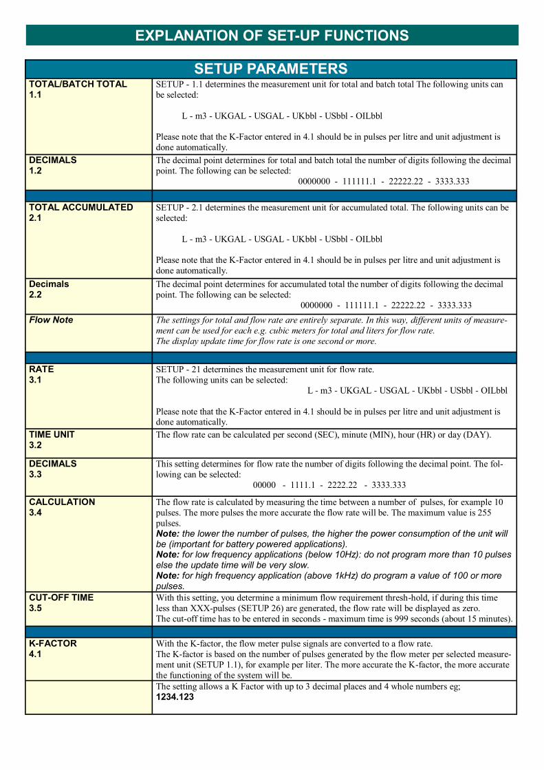
SETUP PARAMETERS TOTAL/BATCH TOTAL 1.1
SETUP - 1.1 determines the measurement unit for total and batch total The following units can
be selected:
L - m3 - UKGAL - USGAL - UKbbl - USbbl - OILbbl
Please note that the K-Factor entered in 4.1 should be in pulses per litre and unit adjustment is
done automatically.
DECIMALS 1.2
The decimal point determines for total and batch total the number of digits following the decimal
point. The following can be selected:
0000000 - 111111.1 - 22222.22 - 3333.333
TOTAL ACCUMULATED 2.1
SETUP - 2.1 determines the measurement unit for accumulated total. The following units can be
selected:
L - m3 - UKGAL - USGAL - UKbbl - USbbl - OILbbl
Please note that the K-Factor entered in 4.1 should be in pulses per litre and unit adjustment is
done automatically.
Decimals 2.2
The decimal point determines for accumulated total the number of digits following the decimal
point. The following can be selected:
0000000 - 111111.1 - 22222.22 - 3333.333
Flow Note The settings for total and flow rate are entirely separate. In this way, different units of measure-
ment can be used for each e.g. cubic meters for total and liters for flow rate.
The display update time for flow rate is one second or more.
RATE 3.1
SETUP - 21 determines the measurement unit for flow rate.
The following units can be selected:
L - m3 - UKGAL - USGAL - UKbbl - USbbl - OILbbl
Please note that the K-Factor entered in 4.1 should be in pulses per litre and unit adjustment is done automatically.
TIME UNIT 3.2
The flow rate can be calculated per second (SEC), minute (MIN), hour (HR) or day (DAY).
DECIMALS 3.3
This setting determines for flow rate the number of digits following the decimal point. The fol-
lowing can be selected:
00000 - 1111.1 - 2222.22 - 3333.333
CALCULATION 3.4
The flow rate is calculated by measuring the time between a number of pulses, for example 10
pulses. The more pulses the more accurate the flow rate will be. The maximum value is 255
pulses.
Note: the lower the number of pulses, the higher the power consumption of the unit will be (important for battery powered applications). Note: for low frequency applications (below 10Hz): do not program more than 10 pulses else the update time will be very slow. Note: for high frequency application (above 1kHz) do program a value of 100 or more pulses.
CUT-OFF TIME 3.5
With this setting, you determine a minimum flow requirement thresh-hold, if during this time
less than XXX-pulses (SETUP 26) are generated, the flow rate will be displayed as zero.
The cut-off time has to be entered in seconds - maximum time is 999 seconds (about 15 minutes).
K-FACTOR 4.1
With the K-factor, the flow meter pulse signals are converted to a flow rate.
The K-factor is based on the number of pulses generated by the flow meter per selected measure-
ment unit (SETUP 1.1), for example per liter. The more accurate the K-factor, the more accurate
the functioning of the system will be.
The setting allows a K Factor with up to 3 decimal places and 4 whole numbers eg;
1234.123
EXPLANATION OF SET-UP FUNCTIONS

The PR unit cam only accept a reed switch input, this sensor has been selected as the most common sensor and requires very little power with small effect on battery life. The 2 position terminal block is not polarity conscious so the reed switch wires can be connected in any order. Connecting any other sensor type could cause damage to the elec-tronics module
PR
1. Rubber Boot
2. Cover Screws
3. LCD Cover
4. Cover O-Ring
5. LC Display
6. Battery
7. PCB Sensor
8. Polypropylene Housing
SERVICE KITS
Part Number Items
MXS-DIS-PR
2. Cover Screws
3. LCD Cover
4. Cover O-Ring
5. LC Display
6. Battery
MXS-PCB-PR
7. PCB Sensor Board
8. PP Housing
SERVICE KITS

WALL MOUNT BRACKETS
The PR series is available with a Wall Mount Bracket option for applications requiring remote mount display. Following is a dimensional drawing for the wall mount bracket.

GENERAL Display
Type High intensity reflective numeric and alphanumeric LCD, UV-resistant.
Digits Seven 12mm (0.47") and seven 8mm (0.31"). Various symbols and measuring units.
Refresh rate Flow Rate: once per second. Total: 8 times/second after key press to one second.
Enclosures
General Control Keys
Aluminium with Polycarbonate window, silicone and EPDM gaskets. UV stabilized and flame retardant material. Two industrial micro-switch keys. UV-resistant silicone keypad.
Meter mount enclosures Classification
Cable entry
Dimensions: 100mm diameter IP67 Black Anodised
Operating temperature
Operational -20°C to +60°C (-4°F to +140°F).
Power supply
Battery powered Lithium battery - life-time depends upon settings - up to 3 years @ 20°C.
Terminal connections
Type: Terminal strip. Wire max. 1mm2
Data protection
Type Backup of all settings and running totals in flash memory.
Environment
Electromagnetic compatibility Compliant ref: EN 61326-1:2006, EN61010-1:2001
INPUT
Flow Meter
Type reed-switch
Frequency Total: minimum 0 Hz - maximum 120 Hz for total Flow Rate: 0.01 Hz – maximum 120Hz.
K-Factor 0000.001 - 9,999.999 pulses per unit of measure
Operator functions
Displayed functions Flow Rate. Total (can be reset to zero by the operator). Batch total (can be reset to zero by the operator). Accumulated total (non resettable)
Total / Batch total / Accumulated total
Digits 7 digits.
Units L, m3, US-GAL, UK-GAL, US-bbl, UK-bbl, OIL-bbl.
Decimals 0 - 1 - 2 or 3.
Note total and batch total can be reset to zero.
Flow Rate
Digits 7 digits.
Units L, m3, US-GAL, UK-GAL, US-bbl, UK-bbl, OIL-bbl.
Decimals 0 - 1 - 2 or 3.
Time units /sec - /min - /hr .
TECHNICAL SPECIFICATIONS