Embed Size (px)
Citation preview
Multiuser TH-precoding for TDD–CDMA overmultipath channels
I. Berenguer, A. Høst-Madsen and X. Wang
Abstract: Nonlinear precoding schemes for downlink time-division duplex–CDMA systems overmultipath fading channels, are considered. First, the capacity results of a downlink CDMA systemwith either multiuser detection or precoding, were obtained and compared. It is seen that the twoschemes exhibit similar capacity regions for both sum rate and maximum equal rate, which motiv-ates the development of efficient nonlinear transmitter precoding techniques to reduce the receivercomplexity at the mobile units without degrading the system performance. We then develop bothbit-wise and chip-wise Tomlinson–Harashima (TH) multiuser precoding methods for downlinkCDMA with multipath, to remove multi-user interference, inter-chip interference and inter-symbolinterference. Efficient algorithms for multiuser power loading and ordering are also developed.Implementation of the proposed TH-precoding schemes in time-varying channels based onchannel prediction is addressed as well. Simulations results are provided to demonstrate the effec-tiveness of the proposed techniques in suppressing interference in downlink CDMA.
1 Introduction
Multiuser detection (MUD) techniques are consideredpowerful for interference suppression in CDMA systems,especially in uplinks, where the base-station receiver hasthe knowledge of all users’ spreading sequences andchannel states, and can perform sophisticated signal proces-sing [1]. In the downlinks, however, the mobile receivertypically has only the knowledge of its own spreadingsequence and channel state. Although adaptive linearMUD (either training-based or blind) can be employed forsuch scenario, the performance can be limited because ofthe linear constraint on the detector. Moreover, the powerconstraint of the mobile calls for simple receiver processing.On the other hand, the precoding schemes for downlinkCDMA effiectively transfer the signal processing forinterference suppression from the mobile receiver to thebase-station transmitter. This approach is feasible if thebase-station can estimate the downlink channels of allusers [e.g. in systems employing time-division duplexing(TDD) where the uplink and downlink channels are recipro-cal]. In [2], a precoding method was proposed which isessentially an implementation of the RAKE receiver at thetransmitter. Hence this approach does not attempt to miti-gate the multiple-access interference (MAI). Recently,different linear precoding techniques have been proposedto combat MAI and inter-chip interference but without con-sidering inter-symbol interference (ISI) [3, 4]. If the ISI ispresent then the complexity of these techniques becomes
# The Institution of Engineering and Technology 2007
doi:10.1049/iet-com:20060510
Paper first received 31st August 2006 and in revised form 22nd January 2007
I. Berenguer is with the Department of Engineering, University of Cambridge,Cambridge, UK
A. Høst-Madsen is with the Department of Electrical Engineering, University ofHawaii, Honolulu, Hawaii
X. Wang is with the Department of Electrical Engineering, Columbia University,New York, NY, USA
E-mail: [email protected]
IET Commun., 2007, 1, (4), pp. 739–750
prohibitive since the dimension of the matrix filter is pro-portional to the data frame length multiplied by thenumber of users (i.e. block processing). More recently,bit-wise linear precoding methods have been proposed toreduce the precoding complexity in the presence ISI [5].
The downlink CDMA is a special case of broadcast chan-nels. There has been significant recent interest in character-ising the capacity of broadcast channels. In particular, it hasbeen shown that when the interference is non-causallyknown to the transmitter and unknown to the receiver, thecapacity is the same as if the interference were notpresent – a result known as ‘dirty paper coding’. Theseresults were originally proved for Gaussian channels [6],and have been generalised to other types of causal interfer-ence [7–9]. Several practical suboptimal implementationsof dirty paper coding based on Tomlinson–Harashima(TH) precoding [10, 11] have been proposed, for examplefor digital subscriber line systems [12], for multi-antennasystems [13, 14] and CDMA systems [15].
In this paper, we first obtain the capacity regions of adownlink CDMA system employing either MUD or precod-ing. It is seen that these two approaches provide similarcapacity regions, but not equivalent, suggesting that precod-ing can potentially achieve similar performance offered byMUD and reduce the complexity of the mobile user. Thismotivates the development of practical approaches to ‘dirty-paper coding’ for downlink TDD–CDMA systems that willbe presented in the second part of the paper.
In the second part of the paper, we extend the nonlinearprecoding method in [15] to systems with simpler receivers,that is without channel state information (CSI) and with ISI.Note that the work in [15] assumes that each userimplements a RAKE receiver and hence assumes the knowl-edge of CSI at the receiver. In CDMA systems, we havemore degrees of freedom: the combination of (a) the spread-ing at the transmitter, (b) despreading at the receiver, (c)operations at the receiver and (d) precoding operation forcancelling MUI, ICI and ISI can be implemented in manydifferent ways given different results, as shown in thispaper. In particular, in this paper, we propose a new
739

chip-wise precoding scheme that combines the spreadingand TH-precoding operations. Our results show that witha similar complexity at the transmitter, our chip-wise sol-ution with only a fixed matched filter (to the original spread-ing sequence) at the receiver can outperform the THprecoder with a RAKE receiver (i.e. with CSI at the recei-ver) proposed in [14, 15]. Furthermore, efficient algorithmsfor multiuser power loading and ordering are developed.Implementation of the proposed TH-precoding schemes intime-varying channels based on channel prediction is alsoaddressed.
2 Downlink capacity regions of MUD andprecoding
In TDD systems, the uplink channel and the downlinkchannel for each individual user is the same. Hence thebase station can use the uplink channel information toperform preprocessing for the downlink and thereby transfersophisticated signal processing from the receiver end to thetransmitter end, that is to replace MUD (receiver proces-sing) by precoding (transmitter processing). In thissection, we present and compare the capacity results of pre-coding and MUD in the downlink of a CDMA system.These two approaches for downlink CDMA are illustratedschematically in Fig. 1. Note that this is a special case ofthe multiple-input multiple-output (MIMO) broadcastchannel for which recent progressive developments [7,16–19] have led to what is considered as the final solutionto the capacity region for the general broadcast channel[20]. In what follows, we use results from [7, 20] toobtain and compare the capacity regions of precoding andMUD in the downlink of a CDMA system.
Consider a synchronous CDMA system with K users sig-nalling over a real-valued AWGN channel. Let fk and sk bethe channel gain and the spreading signature of the kth user,respectively. Denote S ¼ [s1, . . ., sK]. Then R ¼ STS is theK � K cross-correlation matrix of the spreading waveformsof all users.
2.1 Multiuser detection
Assume that the users are ordered according to theirpath gains so that f1 � f2 � � � � � fK. The received signalat the kth mobile receiver is given by rk ¼fkPK
‘¼1 x‘s‘ þ nk , where nk � N (0, I). Note that in thiscase symbols from different users x1, . . . , xK are indepen-dently encoded. Denote x ¼ [x1, . . . , xK]T. A sufficient
Fig. 1 Schematic illustration of MUD and precoding in downlinkCDMA systems
740
statistic for x is the output of a bank of matched-filters [1]
yk W [sT1 rk , s
T2 rk , � � � , sT
Krk]T¼ fkRxþ vk (1)
with E{vkvTk } ¼ R. The kth user then makes a decision on its
own data xk based on yk. Denote rk as the kth column of Rand
Qk WRþ f 2k
Xk�1
‘¼1
P‘r‘rT‘ (2)
where Pk WE{x2k}. Denote PT W
PKk¼1 Pk as the total trans-
mit power. We have the following result regarding an outerbound on the rate region.
Proposition 1: Consider the channel model (1) and supposethat each user’s data is encoded independently. Then themultiuser rate tuple (R1, . . . , RK) must satisfy
Rk �1
2log 1 þ Pk f
2k r
TkQ
�1k rk
� �, k ¼ 1, . . . ,K (3)
for some Pk ¼ 1, . . . ,K, satisfying Pk � 0 andPKk¼1 Pk ¼ PT.
Proof: Define y0k ¼ yk=fk . Then we can rewrite the follow-ing equivalent model to (1)
y01 ¼ Rxþ u01 and y
0k ¼ y
0k�1 þ u0k , k ¼ 2, . . . , K (4)
where the u01, . . . , u0K are independent, zero-mean Gaussian
vectors, and E{u0ku0Tk } ¼ f
�2k R. The model (4) is the same as
the aligned degraded broadcast channel model in [20]. Thedifference is that here each xk is encoded independently.This corresponds to the model in [20] with Bi zero exceptfor the ith diagonal element and S a diagonal matrix. Itcan be checked that the proof still applies with these restric-tions, and we therefore obtain a rate given in [20], whichhere becomes
Rk �1
2log
detPk
‘¼1 P‘r‘rT‘ þ
Pk‘¼1 E{u0‘u
T‘ }
� �det
Pk�1‘¼1 P‘r‘r
T‘ þ
Pk‘¼1 E{u0‘u
T‘ }
� �0@
1A
¼1
2log
det (Qk þ f2k Pkrkr
Tk
detQk
� � (5)
Let Fk be a Cholesky factor of Qk, that is FkFTk ¼ Qk . Then
det (Qk þ Pkf2k rkr
Tk )
¼ det Fk I þffiffiffiffiffiPk
pfkF
�1k rk
� � ffiffiffiffiffiPk
pfkF
�1k rk
� �T� �
FTk
� ¼ (1 þ Pkf
2k r
TkQ
�1k rk) detQk (6)
where in (6) we used the following identity det (AB) ¼ det(BA) ¼ det (A) det (B), and det (Iþ aaT) ¼ aTaþ 1, wherea is a vector. Substituting (6) into (5) we obtain (3). A
The rate in Proposition 1 is achievable with a multiuserdetector that performs serial interference cancellation onweak users and linear MMSE interference suppression onstrong users. In particular, user k can decode the dataintended for users kþ 1, . . . , K as user k receives thesame signal but with higher SNR. Suppose that user k hasdecoded users kþ 1, . . . , K. It then subtracts the signals
IET Commun., Vol. 1, No. 4, August 2007
of these users from yk in (1) to obtain
~yk ¼ yk � fk
XK‘¼kþ1
r‘x‘ ¼ fk
Xk‘¼1
r‘x‘ þ uk
¼ fkrkxk þ fk
Xk�1
‘¼1
r‘x‘ þ uk (7)
It now applies a linear MMSE filter on ~yk . Note that thecovariance matrix of the noise and interference is givenby Qk in (2). The linear MMSE filter output is given by
xk ¼ mTk ~yk , with mk ¼ fkQ
�1k rk (8)
This gives a rate
Rk ¼1
2log 1 þ
(rTkQ
�1k rk)2Pkf
2k
rTkQ
�1k rk
!
¼1
2log (1 þ Pk f
2k r
TkQ
�1k rk)
(9)
when K ¼ 2, denote r W r1,2 ¼ r2,1. The above rate regioncan be easily evaluated as
R1 ¼1
2log (1 þ P1 f
21 ) (10)
R2 ¼1
2log 1 þ
1 þ P1 f2
2 (1 � r2)
1 þ P1 f2
2
P2 f2
2
� �
¼1
2log 1 þ 1 � r2 P1 f
22
1 þ P1 f2
2
� �P2 f
22
� �(11)
2.2 Precoding
In systems employing precoding, each downlink usersimply applies a filter matched to its own spreadingsequence. The output of this matched-filter is given byyk ¼ fkr
Tk xþ uk , where x is the precoded vector. Stacking
the output of the matched-filters of all users in a singlevector, we then obtain the downlink precoding signalmodel: y ¼ ARxþ u, where A ¼ diag( f1, . . . , fK) andEfuuT
g ¼ I. This is similar to a multiple-antenna broadcastchannel [7]. However, note that here the power of the trans-mitted signal is EfxT Rxg. Therefore the power constraint isEfxT Rxg � PT, which is different from [7]. This is easilyfixed: let F be the Cholesky factor of R, that is FFT ¼ R.Define u ¼ FTx. Then u should satisfy the power constraintEfuTug � PT, and we can write the received signal as
y ¼ ARF�Tuþ u ¼ AFuþ u (12)
This is the same as the model in [7] for a broadcast chan-nel with K antennas at the base station and one antenna ateach terminal, with H W AF. In [7], Costa’s ‘dirty-papercoding’ was suggested, and very recently in [20] it wasshown that this scheme actually gives the capacity region.Hence the results in [7] apply to the current problem andthe following rate is achievable [17]
Rk ¼1
2log
det I þ hTk
PK‘¼k S‘
� �hk
� �det I þ hT
k
PK‘¼kþ1 S‘
� �hk
� � (13)
where S1, . . . , SK are positive semidefinite matrices satisfy-ing tr(
PKk¼1 Sk) � PT and hT
k is the kth row of H. Thecapacity region, as proved in [20], is the convex unionover all matrices S1, . . . , SK and all orderings of theusers. Unfortunately, except for the two-user case solved
IET Commun., Vol. 1, No. 4, August 2007
in [7], no closed-form solution for the capacity region hasbeen found.
For the case of K ¼ 2, we can obtain explicit expressionsfor the capacity region. In [7], it was proved that thecapacity region is given by
R1 � log 1 þac1PT
1 þ q(1 � a)c1PT
� �(14)
R2 � log (1 þ p(1 � a)c1PT), 0 � q � 1, 0 � a � 1 (15)
where c1 W hT1h1, c2 W j det (H)j2=c1, c3 W jhT
1h2j2=c2
1
and
p ¼ffiffiffiffiffiffiffic3q
pþ
ffiffiffiffiffiffiffiffiffiffiffiffiffiffiffiffiffiffiffic2
c1
(1 � q)
r� �2
(16)
We can obtain a more explicit expression as follows. Firstset equality in (14) and solve for q, to obtain
q ¼2R1 � 1 � ac1PT
(1 � a)c1PT(1 � 2R1 )(17)
Then substitute (17) into (16) and in (15) with equality, andsolve for a from dR2/da ¼ 0, to obtain the unique solution
a ¼
�c21PT þ 2R1c2
1c3PT
�22R1c2 � c1c3 þ 23R1c2 þ 2R1c1c3
(c1c3 þ 2R1c2)2R1c1PT
(18)
Substituting (18) into (14) and (15), we obtain
R1 � log (1 þ c1PT) (19)
R2 � log 1 þ
c21c3PT þ c1c3 þ 2R1
�(c1c2PT þ c2 � c1c3 � c22R1 )
c12R1
0BBB@
1CCCA (20)
Now substituting (19) with equality into (20), and usingthe definitions of ci and H W AF, after some straightforwardbut tedious simplifications, we obtain
R1 �1
2log (1 þ P1 f
21 ) (21)
R2 �1
2log 1 þ 1 � r2 P1 f
21
1 þ P1 f2
1
� �P2 f
22
� �(22)
If we swap the order of the users, we obtain anotherregion, and the total region is the convex closure of thesetwo regions.
2.3 Numerical comparisons
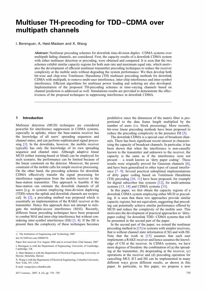
We next provide some numerical results comparing thedownlink CDMA capacity regions for MUD and precodingwith K ¼ 2. First, we notice that the two capacityexpressions (10) and (11), and (21) and (22) are verysimilar. Fig. 2 shows typical rate regions, one for highSNR and one for low SNR. There are two curves for the pre-coding case because of the dependency on user ordering(the capacity region is the convex union) and one curvefor the MUD case. It is seen that the regions are quitesimilar. The maximum sum rate is slightly larger forMUD, whereas the maximum equal rate (i.e. R1 ¼ R2) isslightly larger for precoding. This turns out to be general,as the following numerical results show. Fig. 3 shows thesum rate as a function of f2/f1 and r [ [0, 1] with f1fixed. It is seen that the sum rate for MUD is consistently
741
better, but only slightly. Similar observation can be madefor maximum equal rate in Fig. 4. In summary, it is seenthat precoding can potentially provide similar capacityas MUD, which motivates the development of practicaltransmitter precoding techniques as an alternative toMUD to reduce the complexity of the mobile receiver. Inthe following sections, we consider more realistic scenarios(i.e. frequency selective channels and larger numberof users) for which we propose suboptimal approachesto ‘dirty-paper coding’ based on the TH precodingtechnique.
3 TH precoding in downlink CDMA
3.1 Downlink CDMA system model
We consider a K-user discrete-time downlink CDMAsystem signalling over multipath channels. Denotebk[i] [ A as the information symbol of the kth usertransmitted during the ith symbol interval, where A is afinite constellation set; and b[i] ¼ [b1[i], . . . , bK[i]]T.Denote the symbol by symbol precoding operation asx[i] ¼ C(b[i], . . . , b[i2 nþ 1]), where x[i] is the K � 1precoded symbol vector based on n information symbolvectors. Denote N as the spreading factor andsk ¼ [sk,1, . . . , sk,N]T as the spreading waveform of the kthuser. Then the signal transmitted from the base stationduring the ith symbol interval can be written as p[i] ¼
Fig. 2 Comparisons of rate regions for MUD and precoders withK ¼ 2
a High SNRb Low SNR
742
Sx[i], where S ¼ [s1, s2, . . ., sK]. The vector p[i] is passedthrough a parallel-to-serial converter and transmitted overthe wireless channel. The path delays are assumed to beintegral multiples of the chip interval. Denote the multipathchannel seen by the kth user as fk ¼ [ fk,1, fk,2, . . . , fk,L]T,where L is the number of resolvable paths and fk,l is thecomplex fading gain corresponding to the lth path of thekth user. We assume that L � N, so that the delay spreadis at most one symbol interval.
Denote rk[i] as the N � 1 received signal vector by thekth user during the ith symbol interval (i.e. N consecutivechip intervals). Then
rk[i] ¼ DkSx[i] þ �DkSx[i� 1] þ nk[i] (23)
where nk[i] � Nc(0, s 2n IN ) is the complex white Gaussian
noise vector at the kth receiver,
Dk ¼
fk,1 0 . . . 0
fk,2 fk,1 0 . .. ..
.
..
. . .. . .
.0
0 . . . fk,L . . . fk,1
2666664
3777775
N�N
and
Fig. 3 Sum rate for precoding and MUD as a function of r andf2/f1 (SNR is 20 dB for user 1)
a Sum rate for precoding and MUD (almost equal, so the two surfacesare nearly indistinguishable)b Difference between sum rates for precoding and MUD(Rprecoding 2 RMUD)
IET Commun., Vol. 1, No. 4, August 2007
�Dk ¼
0 . . . fk,L . . . fk,2
0 . . . . .. . .
. ...
..
. . .. . .
.0 fk,L
0 . . . . . . 0
2666664
3777775
N�N
At the kth mobile receiver, a matched-filter is applied to the
received signal rk[i] with this user’s signature waveform,
that is yk[i] ¼ sHk rk[i]. By stacking the matched-filter
output from all users into a single vector we have
sH1 r1[i]
sH2 r2[i]
..
.
sHK rK [i]
266664
377775
|fflfflfflfflfflfflffl{zfflfflfflfflfflfflffl}y[i]
¼
sH1 D1S
sH2 D2S
..
.
sHKDKS
266664
377775
|fflfflfflfflfflfflffl{zfflfflfflfflfflfflffl}H
x[i] þ
sH1�D1S
sH2�D2S
..
.
sHK�DKS
266664
377775
|fflfflfflfflfflfflffl{zfflfflfflfflfflfflffl}�H
x[i� 1]
þ
sH1 n1[i]
sH2 n2[i]
..
.
sHKnK [i]
266664
377775
|fflfflfflfflfflfflfflffl{zfflfflfflfflfflfflfflffl}u[i]
(25)
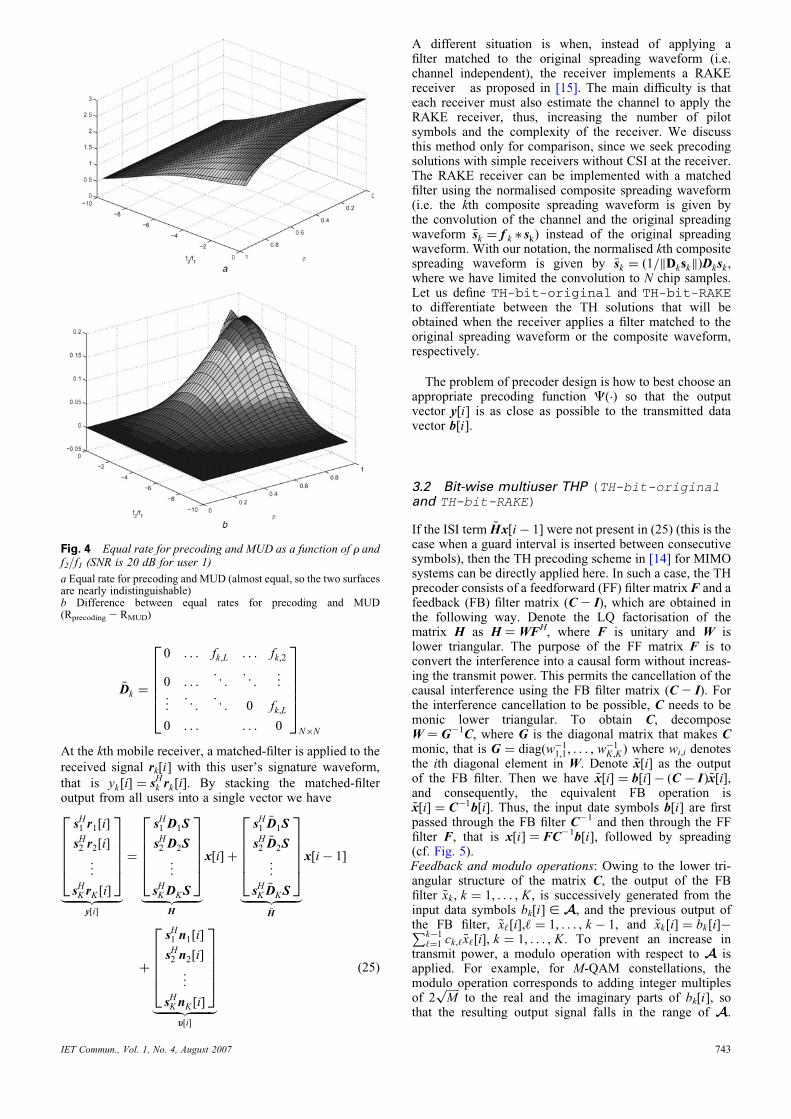
Fig. 4 Equal rate for precoding and MUD as a function of r andf2/f1 (SNR is 20 dB for user 1)
a Equal rate for precoding and MUD (almost equal, so the two surfacesare nearly indistinguishable)b Difference between equal rates for precoding and MUD(Rprecoding 2 RMUD)
IET Commun., Vol. 1, No. 4, August 2007
A different situation is when, instead of applying afilter matched to the original spreading waveform (i.e.channel independent), the receiver implements a RAKEreceiver as proposed in [15]. The main difficulty is thateach receiver must also estimate the channel to apply theRAKE receiver, thus, increasing the number of pilotsymbols and the complexity of the receiver. We discussthis method only for comparison, since we seek precodingsolutions with simple receivers without CSI at the receiver.The RAKE receiver can be implemented with a matchedfilter using the normalised composite spreading waveform(i.e. the kth composite spreading waveform is given bythe convolution of the channel and the original spreadingwaveform �sk ¼ f k � sk) instead of the original spreadingwaveform. With our notation, the normalised kth compositespreading waveform is given by �sk ¼ ð1=kDkskkÞDksk ,where we have limited the convolution to N chip samples.Let us define TH-bit-original and TH-bit-RAKEto differentiate between the TH solutions that will beobtained when the receiver applies a filter matched to theoriginal spreading waveform or the composite waveform,respectively.
The problem of precoder design is how to best choose anappropriate precoding function C(.) so that the outputvector y[i] is as close as possible to the transmitted datavector b[i].
3.2 Bit-wise multiuser THP (TH-bit-originaland TH-bit-RAKE)
If the ISI term �Hx[i� 1] were not present in (25) (this is thecase when a guard interval is inserted between consecutivesymbols), then the TH precoding scheme in [14] for MIMOsystems can be directly applied here. In such a case, the THprecoder consists of a feedforward (FF) filter matrix F and afeedback (FB) filter matrix (C2 I), which are obtained inthe following way. Denote the LQ factorisation of thematrix H as H ¼ WFH, where F is unitary and W islower triangular. The purpose of the FF matrix F is toconvert the interference into a causal form without increas-ing the transmit power. This permits the cancellation of thecausal interference using the FB filter matrix (C2 I). Forthe interference cancellation to be possible, C needs to bemonic lower triangular. To obtain C, decomposeW ¼ G21C, where G is the diagonal matrix that makes Cmonic, that is G ¼ diag(w�1
1,1, . . . , w�1K,K ) where wi,i denotes
the ith diagonal element in W. Denote ~x[i] as the outputof the FB filter. Then we have ~x[i] ¼ b[i] � (C � I)~x[i],and consequently, the equivalent FB operation is~x[i] ¼ C�1b[i]. Thus, the input date symbols b[i] are firstpassed through the FB filter C21 and then through the FFfilter F, that is x[i] ¼ FC21b[i], followed by spreading(cf. Fig. 5).Feedback and modulo operations: Owing to the lower tri-angular structure of the matrix C, the output of the FBfilter ~xk , k ¼ 1, . . . , K, is successively generated from theinput data symbols bk[i] [ A, and the previous output ofthe FB filter, ~x‘[i],‘ ¼ 1, . . . , k � 1, and ~xk[i] ¼ bk[i]�Pk�1
‘¼1 ck,‘ ~x‘[i], k ¼ 1, . . . , K. To prevent an increase intransmit power, a modulo operation with respect to A isapplied. For example, for M-QAM constellations, themodulo operation corresponds to adding integer multiplesof 2
ffiffiffiffiffiM
pto the real and the imaginary parts of bk[i], so
that the resulting output signal falls in the range of A.
743
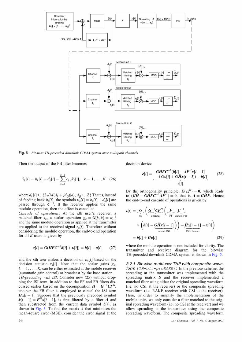
Fig. 5 Bit-wise TH-precoded downlink CDMA system over multipath channels
Then the output of the FB filter becomes
~xk[i] ¼ bk[i] þ dk[i] �Xk�1
‘¼1
ck,‘ ~x‘[i], k ¼ 1, . . . , K (26)
where dk[i] [ {2 Mp
(dI þ jdQ)jdI , dQ [ Z} That is, instead
of feeding back bk[i], the symbols uk[i] ¼ bk[i] þ dk[i] arepassed through C21. If the receiver applies the samemodulo operation, then the effect is cancelled.Cascade of operations: At the kth user’s receiver, amatched-filter sk, a scalar operation gk ¼ G[k, k] ¼ w�1
k,k
and the same modulo operation as applied at the transmitterare applied to the received signal rk[i]. Therefore withoutconsidering the modulo operation, the end-to-end operationfor all K users is given by
z[i] ¼ G(HFC�1b[i] þ u[i]) ¼ b[i] þ u[i] (27)
and the kth user makes a decision on bk[i] based on thedecision statistic zk[i]. Note that the scalar gains gk,k ¼ 1, . . . , K, can be either estimated at the mobile receiver(automatic gain control) or broadcast by the base station.TH-precoding with ISI: Consider now (25) without drop-ping the ISI term. In addition to the FF and FB filters dis-cussed earlier based on the decomposition H ¼ G21CFH,another the FB filter is employed to cancel the ISI term�Hx½i� 1�. Suppose that the previously precoded symbol~x[i� 1] ¼ FHx[i� 1], is first filtered by a filter A andthen substracted from the current data symbol b[i], asshown in Fig. 5. To find the matrix A that minimises themean-square error (MSE), consider the error signal at the
744
decision device
e[i] ¼GHFC�1(b[i] � AFHx[i� 1]
þGu[i] þ G �Hx[i � 1]) � b[i]|fflfflfflfflfflfflfflfflfflfflfflfflfflfflfflfflfflfflfflfflfflfflfflfflfflfflfflffl{zfflfflfflfflfflfflfflfflfflfflfflfflfflfflfflfflfflfflfflfflfflfflfflfflfflfflfflffl}z[i]
(28)
By the orthogonality principle, EfezHg ¼ 0, which leadsto (G �H � GHFC�1AFH ) ¼ 0, that is A ¼ G �HF. Hencethe end-to-end cascade of operations is given by
z[i] ¼ G|{z}rx
�G�1CFH|fflfflfflfflffl{zfflfflfflfflffl}
channel
�F|{z}FF
C�1|{z}cancel,FB
�
�b[i] � G �Hx[i� 1]|fflfflfflfflfflfflfflffl{zfflfflfflfflfflfflfflffl}
cancel ISI
��þ �Hx[i� 1]|fflfflfflfflfflffl{zfflfflfflfflfflffl}
ISI channel
þ u[i]
�
¼ b[i] þ Gu[i] (29)
where the modulo operation is not included for clarity. Thetransmitter and receiver diagram for the bit-wiseTH-precoded downlink CDMA system is shown in Fig. 5.
3.2.1 Bit-wise multiuser THP with composite wave-form (TH-bit-preRAKE): In the previous scheme, thespreading at the transmitter was implemented with thespreading matrix S and the receiver implemented amatched filter using either the original spreading waveform(i.e. no CSI at the receiver) or the composite spreadingwaveform (i.e. RAKE receiver with CSI at the receiver).Here, in order to simplify the implementation of themobile units, we only consider a filter matched to the orig-inal spreading waveform (i.e. no CSI at the receiver) and weallow spreading at the transmitter using the compositespreading waveform. The composite spreading waveform
IET Commun., Vol. 1, No. 4, August 2007
is the convolution of the channel response and the spreadingcode. That is, at the transmitter, we consider the spreadingmatrix S ¼ [s, . . . , sK], where si ¼ (1=kDisik)Disi, i ¼
1, . . . , K and the implementation in Fig. 5 is valid by substi-tuting the transmit spreading operation by S. This operationis equivalent to a pre-RAKE and we denote this scheme asTH-bit-preRAKE. Note that the transmit power does notvary if the individual spreading waveforms are normalised:Assuming an i.i.d. data sequence bk[i], k ¼ 1, . . . ,K from aM-QAM constellation, each output of the modulo operator~xk[i] can be well approximated by an i.i.d. uniform dis-tribution within the shaping region [M, M) [21, 22]. Then,the transmit signal can be written as p[i] � SF ~x[i], with
power E{kSF ~x[i]k2} ¼ M=(M � 1)=tr{SSH}, where wehave used that F is unitary.
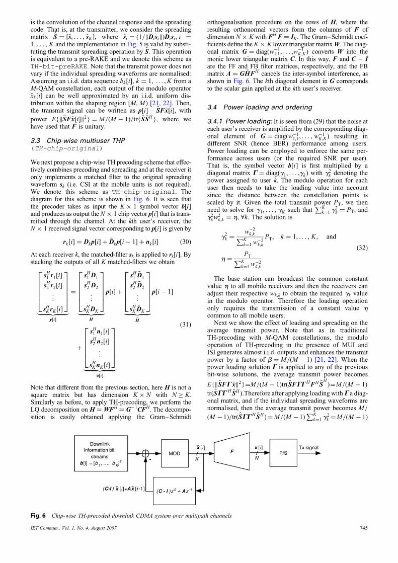
3.3 Chip-wise multiuser THP(TH-chip-original)
We next propose a chip-wise TH precoding scheme that effec-tively combines precoding and spreading and at the receiver itonly implements a matched filter to the original spreadingwaveform sk (i.e. CSI at the mobile units is not required).We denote this scheme as TH-chip-original. Thediagram for this scheme is shown in Fig. 6. It is seen thatthe precoder takes as input the K � 1 symbol vector b[i]and produces as output the N � 1 chip vector p[i] that is trans-mitted through the channel. At the kth user’s receiver, theN � 1 received signal vector corresponding to p[i] is given by
rk[i] ¼ Dkp[i] þ �Dkp[i� 1] þ nk[i] (30)
At each receiver k, the matched-filter sk is applied to rk[i]. Bystacking the outputs of all K matched-filters we obtain
sH1 r1[i]
sH2 r2[i]
..
.
sHK rK [i]
266664
377775
|fflfflfflfflfflfflffl{zfflfflfflfflfflfflffl}y[i]
¼
sH1 D1
sH2 D2
..
.
sHKDK
266664
377775
|fflfflfflfflfflffl{zfflfflfflfflfflffl}H
p[i] þ
sH1�D1
sH2�D2
..
.
sHK�DK
266664
377775
|fflfflfflfflfflffl{zfflfflfflfflfflffl}�H
p[i� 1]
þ
sH1 n1[i]
sH2 n2[i]
..
.
sHKnK [i]
266664
377775
|fflfflfflfflfflfflfflffl{zfflfflfflfflfflfflfflffl}u[i]
(31)
Note that different from the previous section, here H is not asquare matrix but has dimension K � N with N � K.Similarly as before, to apply TH-precoding, we perform theLQ decomposition on H ¼ WFH ¼ G21CFH. The decompo-sition is easily obtained applying the Gram–Schmidt
IET Commun., Vol. 1, No. 4, August 2007
orthogonalisation procedure on the rows of H, where theresulting orthonormal vectors form the columns of F ofdimension N � K with FH F ¼ IK. The Gram–Schmidt coef-ficients define the K � K lower triangular matrix W. The diag-onal matrix G ¼ diag(w�1
1,1, . . . ,w�1K ,K) converts W into the
monic lower triangular matrix C. In this way, F and C – Iare the FF and FB filter matrices, respectively, and the FBmatrix A ¼ G �HFH cancels the inter-symbol interference, asshown in Fig. 6. The kth diagonal element in G correspondsto the scalar gain applied at the kth user’s receiver.
3.4 Power loading and ordering
3.4.1 Power loading: It is seen from (29) that the noise ateach user’s receiver is amplified by the corresponding diag-onal element of G ¼ diag(w�1
1,1, . . . , w�1K,K ) resulting in
different SNR (hence BER) performance among users.Power loading can be employed to enforce the same per-formance across users (or the required SNR per user).That is, the symbol vector b[i] is first multiplied by adiagonal matrix G ¼ diag(g1, . . . ,gk) with g2
k denoting thepower assigned to user k. The modulo operation for eachuser then needs to take the loading value into accountsince the distance between the constellation points isscaled by it. Given the total transmit power PT, we thenneed to solve for g1, . . . , gK such that
PKk¼1 g
2k ¼ PT, and
g2kw
2k,k ¼ h, 8k: The solution is
g2k ¼
w�2k,kPK
k¼1 w�2k,k
PT, k ¼ 1, . . . , K , and
h ¼PTPK
k¼1 w�2k,k
(32)
The base station can broadcast the common constantvalue h to all mobile receivers and then the receivers canadjust their respective wk,k to obtain the required gk valuein the modulo operator. Therefore the loading operationonly requires the transmission of a constant value hcommon to all mobile users.
Next we show the effect of loading and spreading on theaverage transmit power. Note that as in traditionalTH-precoding with M-QAM constellations, the modulooperation of TH-precoding in the presence of MUI andISI generates almost i.i.d. outputs and enhances the transmitpower by a factor of b ¼ M=(M � 1) [21, 22]. When thepower loading solution G is applied to any of the previousbit-wise solutions, the average transmit power becomes
E{kSFG ~xk2}¼M=(M � 1)trðSFGGHFH SH
)¼M=(M � 1)
tr(SGG H SH ):Therefore after applying loading withG a diag-onal matrix, and if the individual spreading waveforms arenormalised, then the average transmit power becomes M=
(M � 1)=tr(SGGH SH )¼M=(M � 1)PK
k¼1 g2k ¼M=(M � 1)
Fig. 6 Chip-wise TH-precoded downlink CDMA system over multipath channels
745
PT: On the other hand, assuming that E{jbk [i]j2} ¼ 1, thenthe bit error probability of each user can be well approxi-
mated by Pe ¼ aQ (h=s2n
p)
� �, where a accounts for the
increase in the number of nearest neighbours due to themodulo operation (e.g. in QPSK a ¼ 2) [10, 11].
We next show that when orthogonal spreading sequencesare employed, that is when STS ¼ IK , then we havew
(b)k,k � w
(c)k,k for k ¼ 1, . . . , K, and therefore h(b) � h(c),
where the superscripts b and c denote bit-wise and chip-wise precoders, respectively. First, comparing (25) and(31), we have H(b) ¼ H(c)S. Let uKþ1, . . ., uN be (N2 K)orthonormal vectors in V? W Rn
nspan(S). Define theunitary matrix S0 ¼ [s1, . . . , sK , uKþ1, . . . , uN ] ¼ [S,U]and let
X ¼ [H (b), H (c)U] ¼ H (c)S0 (33)
Since S0 is a unitary transformation, the rows in X and H(c)
maintain the norm and the angles. Therefore if theK � (N2 K) block matrix HcU has any non-zero row (i.e.the projection of the rows of Hc onto span (U) isnon-zero), the norm of the corresponding row in H(b) willbe smaller than in H(c). Now consider the LQ factorisationH(c) ¼ W(c)F(c)H, obtained using Gram–Schmidt on therows of H(c), that is {h
(c)Tk }Kk¼1. Each value w
(c)k,k can be
obtained as follows. Assume that at the kth step of theGram–Schmidt algorithm the orthonormal vectorsf
(c)1 , . . . , f
(c)k�1 (i.e. first k columns in F(c)) have
been obtained from h(c)1 , . . . ,h
(c)k�1, and denote
Uk�1 ¼ span{f(c)1 , . . . , f
(c)k�1}. Then, by simple inspection
from of the structure of the LQ factorisation w(c)k,k is the
norm of ~f(c)
k ¼ projU?k�1
{h(c)k }, where U
?k�1 ¼ RN
nUk�1 and
f(c)k ¼ ~f
(c)
k =w(c)k,k . That is
w(c)k,k ¼ h
(c)k � projUk�1
{h(c)k }
��� ��� ¼ ~f(c)
k
��� ��� (34)
On the other hand, the diagonal elements of W(b) are simi-larly obtained from [H(b), 0K,N2K]. Then, using (33) and(34) we obtain
w(b)k,k ¼ w
(c)k,k � projV?{ ~f
(c)
k }��� ��� (35)
and hence w(b)k,k � w
(c)k,k . Note that when N ¼ K and orthog-
onal spreading sequences are employed, S is unitary andw
(b)k,k ¼ w
(c)k,k for all k, and hence h(b) ¼ h(c) [cf. Fig. 9].
On the other hand, when the spreading sequences S are
non-orthogonal, it is not true that w(b)k,k � w
(c)k,k . However,
we conjecture that h(b)� h(c) still holds.
3.4.2 User ordering: We can optimise the system BERperformance by optimising the diagonal elements of thematrix W such that the common SNR of all users h is maxi-mised. Notice that W is obtained from the LQ decompo-sition of H. The LQ decomposition is essentially theGram–Schmidt orthogonalisation of the rows of H. Thekth diagonal element of W is the length of the projectionof the kth row vector of H onto the orthogonal complementof the space spanned by the first (k2 1) row vectors alreadyorthogonalised. Different ordering in the orthogonalisationprocess results in different diagonal values of W, andhence different values of h. Let P be the set of the K! poss-ible K � K row permutation matrices. Then for any P [ P,PH is a row-permuted version of H, which corresponds to aparticular ordering of the K users in TH-precoding. Denotewk,k(P) as the kth diagonal element of W resulting from theLQ decomposition of PH. Then the optimal row
746
permutation matrix is given by
Popt ¼ arg maxP[P
PTPKk¼1 w
�2k,k (P)
¼ arg minP[P
XKk¼1
w�2k,k (P) (36)
With the optimal permutation Popt, the followingmodifications are needed at the transmitter and receiver:(1) Perform the LQ decomposition as PH ¼ WFH, orH ¼ PT G21CFH; (2) Apply GP at the receiver (i.e.apply the scalar gains according to the optimal order); (3)The FB matrix for removing the ISI becomes A ¼ GP �H .With these modifications, the cascade of operationsbecomes
z[i] ¼ GP|{z}rx
�P
TG
�1CF
H|fflfflfflfflfflfflfflffl{zfflfflfflfflfflfflfflffl}channel
�F|{z}FF
C�1|{z}
cancel,FB
�
�Gb[i] � GP �Hx[i� 1]|fflfflfflfflfflfflfflfflffl{zfflfflfflfflfflfflfflfflffl}
cancel ISI
��þ �Hx[i� 1]|fflfflfflfflfflffl{zfflfflfflfflfflffl}
ISI channel
þu[i]
�
¼ Gb[i] þ GPu[i] (37)
Note that the matrices G, F and C are obtained from PH.Clearly an exhaustive search solution to (36) is compu-
tationally prohibitive. Note that a different ordering in theorthogonalisation results in a different order in the cancel-lation of the interference. Other systems employing non-linear interference cancellation with ordering (for whichlow complexity suboptimal ordering solutions have beenproposed) include: (a) successive multiuser interferencecancellation receivers [23]; or (b) multiple antennaBLAST-like receivers [13, 24, 25]. We next propose asuboptimal algorithm for an approximate solution to (36)that performs especially well in the chip-wise precoderwhen N . K. The proposed algorithm resembles theBLAST-like ordering algorithm in [25]. First note thatQK
k¼1 w2kk is invariant to the permutation matrix P. This
result is easily proved recalling that PH ¼ WFH, withorthonormal columns in F, then
det (HHH ) ¼ det (PT) det (W ) det (WH ) det (P)
¼YKk¼1
w2k,k
(38)
We first consider the simplest case with K ¼ 2 users,then H contains two rows denoted by hT
1 and hT2 .
Without loss of generality, assume that kh2k , kh1k.Next we show that to maximise the objective functionin (36), we should start with hT
2 , that is start by orthogo-nalising the row with minimum wk,k. Recall that wk,k is thelength of the projection of the kth row of H ontothe orthogonal complement of the subspace spanned bythe previous (k2 1) rows already orthogonalised. Thenwe need to show that
1
kh2k2þ
1
kh1 � (hH2 h1=kh2k2)h2k
2
,1
kh1k2þ
1
kh2 � (hH1 h2=kh1k2)h1k
2
(39)
From (38), the products of the denominators on both sides
IET Commun., Vol. 1, No. 4, August 2007
in (39) are equal. Therefore (39) is equivalent to
h1 �hH2 h1
kh2k2h2
����������
2
þ kh2k2 , h2 �
hH1 h2
kh1k2h1
����������
2
þkh1k2
,jhH2 h1j
2
kh2k2
.jhH2 h1j
2
kh2k2
(40)
which is true by the assumption that kh2k , kh1k.When K , 2, we adopt the greedy solution given in
Algorithm 1 that at the kth iteration, orthogonalises the rowwith minimum wk,k. In other words, the algorithm selectsthe row that is the closest to the subspace spanned by therows already chosen. In the algorithm, mp,j ¼ hHp hj and Qi
represents the subset of rows already orthogonalised up tothe ith step. Note that besides finding the ordering P, the
algorithm also provides the LQ decomposition PH ¼ WFH,
since W is given by the GS coefficients mij and the ith row
of F is given by hi. Clearly the complexity of the abovesearch algorithm is O(K2), which is significantly lowerthan the O(K!) complexity of the exhaustive search method.
Algorithm 1: Greedy ordering and LQ decomposition
INPUT: row vectors hT1 , . . . ,hT
K in HP ¼ 0K�K
k1 ¼ arg mini�K{khik};h1 ¼ h1
k1=khk1k;P(1, k1) ¼ 1; Q1 ¼ {k1};
FOR i ¼ 2: KFOR EVERY j [ {{1, . . . , K}nQi�1}uj ¼ hj �
Pi�1p¼1 mp, jhp;
END FORki ¼ arg minj{kujk};hi ¼ uki=kukik; Qi ¼ {Qi�1} < {ki};P(i, ki) ¼ 1;
END FOROUTPUT: matrix P and LQ decomposition
of PH.
4 Simulation results
4.1 TH-precoding with perfect channel knowledge
We first provide simulation results to compare the BER per-formance of the different precoding schemes:
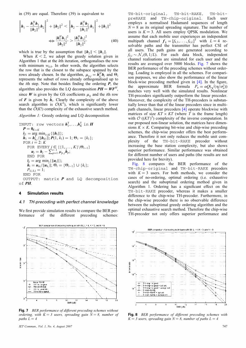
Fig. 7 BER performance of different precoding schemes withoutordering, with K ¼ 3 users, spreading gain N ¼ 8, number ofpaths L ¼ 4
IET Commun., Vol. 1, No. 4, August 2007
TH-bit-original, TH-bit-RAKE, TH-bit-preRAKE and TH-chip-original. Each useremploys a normalised Hadamard sequences of lengthN ¼ 8 as its original spreading signature. The number ofusers is K ¼ 3. All users employ QPSK modulation. Weassume that each mobile user experiences an independentmultipath channel f k ¼ [fk,1, . . . , fk,L]T with L ¼ 4 re-solvable paths and the transmitter has perfect CSI ofall users. The path gains are generated according tofk,i � N c(0, 1=L). For each data block, independentchannel realisations are simulated for each user and theresults are averaged over 5000 blocks. Fig. 7 shows theBER performance of the precoding schemes without order-ing. Loading is employed in all the schemes. For compari-son purposes, we also show the performance of the linearblock-wise precoding method given in [4]. In the figure,the approximate BER formula Pe ¼ aQ( (h=s2
n)p
Þ
matches very well with the simulated results. NonlinearTH-precoders significantly outperform the linear precoder.Moreover, the complexity of the TH-precoders is substan-tially lower than that of the linear precoders since in multi-path channels, linear precoders [4] operate blockwise withmatrices of size KT � KT (where T is the frame length)with O ((KT )3) complexity of the inverse computation. Inour proposed non-linear solution, the matrices have dimen-sions K � K. Comparing bit-wise and chip-wise precodingschemes, the chip-wise precoder offers the best perform-ance. Therefore it not only reduces the mobile unit com-plexity of the TH-bit-RAKE precoder withoutincreasing the base station complexity, but also showssuperior performance. Similar performance was obtainedfor different number of users and paths (the results are notprovided here for brevity).
Fig. 8 compares the BER performance of theTH-chip-original and TH-bit-RAKE precoderswith K ¼ 3 users. For both methods, we consider thecases of no-ordering, optimal ordering (i.e. exhaustivesearch) and the suboptimal ordering method given inAlgorithm 1. Ordering has a significant effect on theTH-bit-RAKE precoder, whereas it makes a smallerdifference to the chip-wise TH-precoder. Furthermore, inthe chip-wise precoder there is no observable differencebetween the suboptimal greedy ordering algorithm and theoptimal exhaustive search method. Therefore the chip-wiseTH-precoder not only offers superior performance and
Fig. 8 BER performance of different precoding schemes withK ¼ 3 users, spreading gain N ¼ 8, number of paths L ¼ 4
747
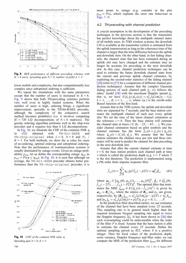
lower mobile unit complexity, but also computationally lesscomplex since suboptimal ordering is sufficient.
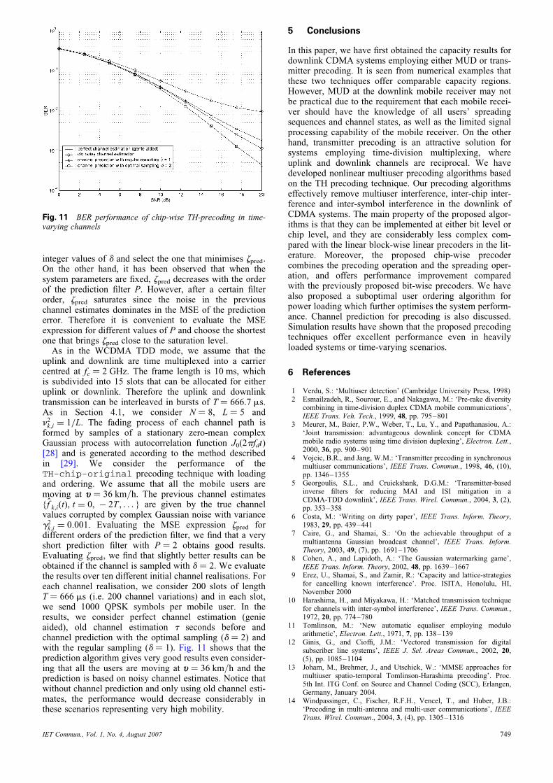
We repeat the simulations with the same parametersexcept that the number of users is increased to K ¼ 6.Fig. 9 shows that both TH-precoding schemes performvery well even in highly loaded systems. When thenumber of users is high, ordering brings a significantimprovement, specially to the TH-bit-RAKE precoder,although the complexity of the exhaustive searchmethod becomes prohibitive (i.e. it involves computingK! ¼ 720 LQ decompositions of 6 � 6 matrices). Thegreedy ordering algorithm performs well in the chip-wiseprecoder and it requires less than 6 LQ decompositions.
In Fig. 10, we illustrate the CDF of the common SNR hin (32) obtained with TH-bit-RAKE andTH-chip-original when L ¼ 4, N ¼ 8 and PT /K ¼ 1. For both methods, we show the h value for casesof no-ordering, optimal ordering and suboptimal ordering.Note that the performance of communication systems isusually dominated by outage events. Given an outage prob-ability pout, let us define the corresponding outage hout aspout ¼ Pr(h � hout). In Fig. 10, it is seen that although onaverage, the TH-bit-RAKE precoder obtains better per-formance than the TH-chip-original precoder, it is
Fig. 10 CDF of the common SNR value h
Spreading gain N ¼ 8, K ¼ 5
Fig. 9 BER performance of different precoding schemes withK ¼ 6 users, spreading gain N ¼ 8, number of paths L ¼ 4
748
more prone to outage (e.g. consider in the plotpout ¼ 3%), which explains the error rate behaviour inFigs. 7–9.
4.2 TH-precoding with channel prediction
A crucial assumption in the development of the precodingtechniques in the previous section is that the transmitterhas perfect knowledge about the multipath channel statesof all mobile users. In TDD wireless systems, the downlinkCSI is available at the transmitter (which is estimated fromthe uplink transmission) as long as the coherence time of thechannel is larger than the time difference between the uplinkand downlink slots. On the other hand, in fast fading chan-nels, the channel state that has been estimated during anuplink slot may have changed and the estimate may nolonger be accurate for precoding in the next downlinkslot. In this case, channel prediction techniques can beused to estimate the future downlink channel state fromthe current and previous uplink channel estimates, byexploiting the second-order statistics of the fading channel[26] (refer to [27] for a comparison of different channel pre-diction techniques). Assume that the complex Gaussianfading process of each channel path fk,i (t) follows theJakes’ model [28] with the maximum Doppler spread fd,that is, we have E{fk,i(t1)fk,i(t2)} ¼ n2
k,iJ0(2pfd jt1 � t2j),k ¼ 1, . . ., K; i ¼ 1, . . ., L, where J0(.) is the zeroth-orderBessel function of the first kind.
Assume that in the TDD system, the uplink and downlinkslots are separated by T seconds; and the base station esti-mates the multipath channel of each user every uplinkslot. We set the time of the latest channel estimation asthe reference t ¼ 0. Then the base station will estimatethe channel state at times t [ f0, 22T, 24T, . . .g. We con-sider channel estimation based on pilot symbols and thechannel estimate has the form fk,i(t) ¼ fk,i(t) þ jk,i(t),where jk,i(t) � N c(0, g2
k,i). We assume that the basestation estimates the channel once per slot and these esti-mates will be used to predict the channel for data precodingin the next downlink slot.
Assume that after the current channel estimate at timet ¼ 0, the base station predicts each channel path at timet which is called the prediction depth (e.g. t ¼ T where Tis the slot duration). The prediction is implemented usinga Pth order finite impulse response filter
~f k,i(t) ¼XPp¼0
wk,i(p)� fk,i( � p2T ) ¼ wHk,i fk,i (41)
where wk,i W wk,i(0), wk,i(1), . . . , wk,i(P)�
T, fk,i W [fk,i(0),
f k,i( � 2T ), . . . , f k,i( � P2T )]T. The optimal filter that mini-
mises the MSE zpred W E{jfk,i(t) � ~f k,i(t)j2} is given by
wk,i ¼ R�1k,i rk,i, where the entries of Rk,i and rk,i are given,
respectively, by [Rk,i]p,q ¼ n2k,iJ0(2pfd jp� qj2T ) þ g2
k,idp,q,
and [rk,i]p ¼ n2k,iJ0(2pfd(tþ p2T )), p, q ¼ 0, 1, . . . , P.
In the prediction filter described earlier, we use estimatesof the channel that have been sampled every 2T seconds.This sampling rate is in general much higher than therequired minimum Nyquist sampling rate equal to twicethe Doppler frequency 2fd. It has been shown in [26] thatsuch oversampling could be unfavourable when the orderof the filter P is fixed. Assume that the base station is ableto estimate the channel every 2T seconds. Define theoptimal sampling period as d2T, where d is a positiveinteger. Then for fixed values of the prediction depth,noise variance, Doppler frequency and filter order, we cancompute the MSE of the prediction filter zpred for different
IET Commun., Vol. 1, No. 4, August 2007
integer values of d and select the one that minimises zpred.On the other hand, it has been observed that when thesystem parameters are fixed, zpred decreases with the orderof the prediction filter P. However, after a certain filterorder, zpred saturates since the noise in the previouschannel estimates dominates in the MSE of the predictionerror. Therefore it is convenient to evaluate the MSEexpression for different values of P and choose the shortestone that brings zpred close to the saturation level.
As in the WCDMA TDD mode, we assume that theuplink and downlink are time multiplexed into a carriercentred at fc ¼ 2 GHz. The frame length is 10 ms, whichis subdivided into 15 slots that can be allocated for eitheruplink or downlink. Therefore the uplink and downlinktransmission can be interleaved in bursts of T ¼ 666.7 ms.As in Section 4.1, we consider N ¼ 8, L ¼ 5 andn2k,i ¼ 1=L. The fading process of each channel path is
formed by samples of a stationary zero-mean complexGaussian process with autocorrelation function J0(2pfdt)[28] and is generated according to the method describedin [29]. We consider the performance of theTH-chip-original precoding technique with loadingand ordering. We assume that all the mobile users aremoving at u ¼ 36 km/h. The previous channel estimates{f k,i(t), t ¼ 0, � 2T , . . . } are given by the true channelvalues corrupted by complex Gaussian noise with varianceg2k,i ¼ 0:001. Evaluating the MSE expression zpred for
different orders of the prediction filter, we find that a veryshort prediction filter with P ¼ 2 obtains good results.Evaluating zpred, we find that slightly better results can beobtained if the channel is sampled with d ¼ 2. We evaluatethe results over ten different initial channel realisations. Foreach channel realisation, we consider 200 slots of lengthT ¼ 666 ms (i.e. 200 channel variations) and in each slot,we send 1000 QPSK symbols per mobile user. In theresults, we consider perfect channel estimation (genieaided), old channel estimation t seconds before andchannel prediction with the optimal sampling (d ¼ 2) andwith the regular sampling (d ¼ 1). Fig. 11 shows that theprediction algorithm gives very good results even consider-ing that all the users are moving at u ¼ 36 km/h and theprediction is based on noisy channel estimates. Notice thatwithout channel prediction and only using old channel esti-mates, the performance would decrease considerably inthese scenarios representing very high mobility.
Fig. 11 BER performance of chip-wise TH-precoding in time-varying channels
IET Commun., Vol. 1, No. 4, August 2007
5 Conclusions
In this paper, we have first obtained the capacity results fordownlink CDMA systems employing either MUD or trans-mitter precoding. It is seen from numerical examples thatthese two techniques offer comparable capacity regions.However, MUD at the downlink mobile receiver may notbe practical due to the requirement that each mobile recei-ver should have the knowledge of all users’ spreadingsequences and channel states, as well as the limited signalprocessing capability of the mobile receiver. On the otherhand, transmitter precoding is an attractive solution forsystems employing time-division multiplexing, whereuplink and downlink channels are reciprocal. We havedeveloped nonlinear multiuser precoding algorithms basedon the TH precoding technique. Our precoding algorithmseffectively remove multiuser interference, inter-chip inter-ference and inter-symbol interference in the downlink ofCDMA systems. The main property of the proposed algor-ithms is that they can be implemented at either bit level orchip level, and they are considerably less complex com-pared with the linear block-wise linear precoders in the lit-erature. Moreover, the proposed chip-wise precodercombines the precoding operation and the spreading oper-ation, and offers performance improvement comparedwith the previously proposed bit-wise precoders. We havealso proposed a suboptimal user ordering algorithm forpower loading which further optimises the system perform-ance. Channel prediction for precoding is also discussed.Simulation results have shown that the proposed precodingtechniques offer excellent performance even in heavilyloaded systems or time-varying scenarios.
6 References
1 Verdu, S.: ‘Multiuser detection’ (Cambridge University Press, 1998)2 Esmailzadeh, R., Sourour, E., and Nakagawa, M.: ‘Pre-rake diversity
combining in time-division duplex CDMA mobile communications’,IEEE Trans. Veh. Tech., 1999, 48, pp. 795–801
3 Meurer, M., Baier, P.W., Weber, T., Lu, Y., and Papathanasiou, A.:‘Joint transmission: advantageous downlink concept for CDMAmobile radio systems using time division duplexing’, Electron. Lett.,2000, 36, pp. 900–901
4 Vojcic, B.R., and Jang, W.M.: ‘Transmitter precoding in synchronousmultiuser communications’, IEEE Trans. Commun., 1998, 46, (10),pp. 1346–1355
5 Georgoulis, S.L., and Cruickshank, D.G.M.: ‘Transmitter-basedinverse filters for reducing MAI and ISI mitigation in aCDMA-TDD downlink’, IEEE Trans. Wirel. Commun., 2004, 3, (2),pp. 353–358
6 Costa, M.: ‘Writing on dirty paper’, IEEE Trans. Inform. Theory,1983, 29, pp. 439–441
7 Caire, G., and Shamai, S.: ‘On the achievable throughput of amultiantenna Gaussian broadcast channel’, IEEE Trans. Inform.Theory, 2003, 49, (7), pp. 1691–1706
8 Cohen, A., and Lapidoth, A.: ‘The Gaussian watermarking game’,IEEE Trans. Inform. Theory, 2002, 48, pp. 1639–1667
9 Erez, U., Shamai, S., and Zamir, R.: ‘Capacity and lattice-strategiesfor cancelling known interference’. Proc. ISITA, Honolulu, HI,November 2000
10 Harashima, H., and Miyakawa, H.: ‘Matched transmission techniquefor channels with inter-symbol interference’, IEEE Trans. Commun.,1972, 20, pp. 774–780
11 Tomlinson, M.: ‘New automatic equaliser employing moduloarithmetic’, Electron. Lett., 1971, 7, pp. 138–139
12 Ginis, G., and Cioffi, J.M.: ‘Vectored transmission for digitalsubscriber line systems’, IEEE J. Sel. Areas Commun., 2002, 20,(5), pp. 1085–1104
13 Joham, M., Brehmer, J., and Utschick, W.: ‘MMSE approaches formultiuser spatio-temporal Tomlinson-Harashima precoding’. Proc.5th Int. ITG Conf. on Source and Channel Coding (SCC), Erlangen,Germany, January 2004.
14 Windpassinger, C., Fischer, R.F.H., Vencel, T., and Huber, J.B.:‘Precoding in multi-antenna and multi-user communications’, IEEETrans. Wirel. Commun., 2004, 3, (4), pp. 1305–1316
749

15 Fischer, R.F.H., Windpassinger, C., Lampe, A., and Huber, J.B.:‘MIMO precoding for decentralized receivers’. Proc. Int. Symp.Information Theory (ISIT), Lausanne, Switzerland, June 2002
16 Boche, H., and Schubert, M.: ‘A general duality theory for uplink anddownlink beamforming’. Proc. IEEE Vehicular Technology Conf.(VTC), Vancouver, Canada, September 2002
17 Vishwanath, S., Jindal, N., and Goldsmith, A.: ‘Duality, achievablerates, and sum-rate capacity of Gaussian MIMO broadcastchannels’, IEEE Trans. Inform. Theory, 2003, 49, (10),pp. 2658–2668
18 Viswanath, P., and Tse, D.: ‘Sum capacity of the vector Gaussianchannel and uplink–downlink duality’, IEEE Trans. Inform. Theory,2003, 49, (8), pp. 1912–1921
19 Yu, W., and Cioffi, J.: ‘Sum capacity of the Gaussian vectorbroadcast channels’, IEEE Trans. Inform. Theory, 2004, 50, (9),pp. 1875–1892
20 Weingarten, H., Steinberg, Y., and Shamai, S. (Shitz).: ‘The capacityregion of the gaussian multiple-input multiple-output broadcastchannel’, IEEE Trans. Inform. Theory, 2006, 52, (9), pp. 3936–3964
21 Forney, G.D., and Eyuboglu, M.V.: ‘Combined equalization and codingusing precoding’, IEEE Commun. Mag., 1991, 29, pp. 25–34
750
22 Trump, T., and Forssen, U.: ‘On the statistical properties of Tomlinsonfilters’ (Telecommunications Theory, Royal Institute of Technology,Stockholm, Sweden, March 1992)
23 Benvenuto, N., Carnevale, G., and Tomasin, S.: ‘Energy optimizationof CDMA transceivers using successive interference cancellation’.Proc. Globecom Dallas, IX, December 2004
24 Windpassinger, C., Vencel, T., and Fischer, R.: ‘Precoding andloading for BLAST-like systems’. Proc. Int. Conf. Wireless andOptical Communication (WOC), Banff, Canada, July 2003
25 Wuebben, D., Boehnke, R., Rinas, J., Kuehn, V., and Kammeyer,K.D.: ‘Efficient algorithm for decoding layered space-time codes’,IEE Electron. Lett., 2001, 37, (22), pp. 1348–1350
26 Duel-Hallen, A., Hu, S., and Hallen, H.: ‘Long-range prediction offading signals: enabling adapting transmission for mobile radiochannels’, IEEE Signal Proc. Mag., 2000, 17, (3), pp. 62–75
27 Semmelrodt, S., and Kattenbach, R.: ‘Investigation of different fadingforecast schemes for flat fading radio channels’. Proc. Vehic. Technol.Conf. (VTC), Orlando, FL, October 2003
28 Jakes, W.C.: ‘Microwave mobile communications’ (Wiley, 1974)29 Dent, P., Bottomley, G.E., and Croft, T.: ‘Jakes fading model
revisited’, Electron. Lett., 1993, 29, (13), pp. 1162–1963
IET Commun., Vol. 1, No. 4, August 2007


![Codebook Based Hybrid Precoding for Millimeter …arXiv:1706.10181v2 [cs.IT] 4 Jul 2017 1 Codebook Based Hybrid Precoding for Millimeter Wave Multiuser Systems Shiwen He, Member, IEEE,](https://img.dokumen.tips/doc/110x75/5f061a127e708231d4164c70/codebook-based-hybrid-precoding-for-millimeter-arxiv170610181v2-csit-4-jul.jpg)


![[IEEE]Blind Adaptive DSCDMA Receivers for Multipath and Multiuser Environments](https://img.dokumen.tips/doc/110x75/58a283b71a28ab891a8b6715/ieeeblind-adaptive-dscdma-receivers-for-multipath-and-multiuser-environments.jpg)