Embed Size (px)
Citation preview

Multibody Dynamic Simulation in Product Development
Tobias Larsson
February 2001
Division of Computer Aided Design Department of Mechanical Engineering
Luleå University of Technology SE-971 87 Luleå, Sweden

ii

iii
Preface
The research presented in this thesis has been carried out at the Division of Computer Aided Design at Luleå University of Technology in Sweden. The research project was initiated and supervised by Professor Lennart Karlsson and Professor Annika Stensson. I wish to express my gratitude to my supervisors for giving me inspiration and support together with stimulating discussions throughout this work. I especially want to thank my close co-authors Lars Drugge, Andreas Larsson and Henrik Johansson for interesting discussions as well as valuable support in times of trouble. My colleagues and friends at the Division of Computer Aided Design have created a nice and stimulating working atmosphere that is highly appreciated. The team at the Department of Mechanical Engineering, Blekinge Institute of Technology, is also given a thought. The Swedish Foundation for Strategic Research, and the Swedish National Rail Administration have provided the gratefully acknowledged financial support. The research has been conducted within the ENDREA1 research program and ENDREA has contributed with a valuable research network as well as interesting courses. The meetings and discussions within the simulation cluster, lead by Professor Sören Andersson at the Royal Institute of Technology, have been really stimulating. Finally, I would like to thank my family, especially Madelene for standing by me and supporting me. My daughter Tilde has brought inspiration, together with some strange keystrokes, thanks! Luleå, February 2001 Tobias Larsson
1 ENDREA – The Swedish Engineering Design Research and Education Agenda

iv

v
Abstract
This thesis deals with multibody dynamic simulation of mechanical systems in the product development process. The approach is to make the process of multibody dynamic simulation more efficient by structuring of simulation models and the method for usage in product development. Previous work has concentrated on developing faster calculation methods and more specialised simulation software. Efforts have been made to clarify how computer tools and multibody dynamic analysis methods are used in product development in industry today. Insight into the knowledge domains of product development and multibody dynamics is given together with an introduction to the areas of distributed simulation, modularisation techniques and non-linear analysis. The mentioned domains have traditionally been separated but the introduction of concurrent engineering and faster computers puts new demands on the need for integration of computer support and analysis in the development process. The performed work is to be seen as cross-functional work in order to bring different domains together for the sake of a better total product development. The application areas used in the work are all within vehicle system dynamics. Clarification of the multibody dynamic simulation methodology has been made in the performed work. A proposal for performing the multibody dynamics methodology in a distributed and modular way in the product development process is given together with a prototype implementation. The prototype system facilitates the idea of distributing analysis possibilities from simulation experts to engineers, hereby increasing the simulation usage in product development. The purpose is to arrive at a simulation driven design rather than a simulation verified design.
Keywords
Multibody dynamic analysis, product development, simulation process.

vi
vii
Thesis
This thesis comprises an introductory part and the following papers:
Paper A
LARSSON, T. & DRUGGE, L. (1998), Dynamic Behaviour of Pantographs due to Different Wear Situations, Computers in Railways VI, Ed. B. Mellitt et al., WIT Press, Southampton, UK, pp. 869-880. ISBN 1-85312-598-9.
Paper B
DRUGGE, L., LARSSON, T., BERGHUVUD, A. & STENSSON, A. (1999), The Nonlinear Behaviour of a Pantograph Current Collector Suspension, DETC-99/VIB-8026, Proceedings of the 1999 ASME Design Engineering Technical Conferences, September 12-15, Las Vegas, Nevada, USA.
Paper C
DRUGGE, L., LARSSON, T. & STENSSON, A. (2000), Modelling and Simulation of Catenary-Pantograph Interaction, Vehicle System Dynamics Supplement 33, pp. 490-501, Swets & Zeitlinger.
Paper D
STENSSON, A., LARSSON, T., MERKT, T.2, SCHULLER, J.3, WILLIAMS, R.A.4 & MAUER, L.5 (2000), Industry Demands on Vehicle Development - Methods and Tools, Vehicle System Dynamics Supplement 33, pp. 202-213, Swets & Zeitlinger.
Paper E
LARSSON, T. & JOHANSSON, H., Product Modularisation with Respect to Dynamic Analysis. Submitted for publication.
Paper F
LARSSON, T., LARSSON, A. & KARLSSON, L. (2001), A Modular Approach to Web Based Multibody Dynamic Simulation, Accepted for publication at CIRP 2001 Design Seminar.
2 Porsche AG, Porschstrase, 712 87 Weissach, Germany 3 BMW AG, 80788 Munchen, Germany 4 Jaguar, Whitley, Coventry CV3 4LF, Great Britain 5 INTEC GmbH, Münchener Straße 20, 82234 Weißling, Germany

viii
ix
Contents
1 INTRODUCTION ......................................................................................................................................1
2 KNOWLEDGE DOMAINS ......................................................................................................................2
2.1 PRODUCT DEVELOPMENT.....................................................................................................................2 2.2 COMPUTER-AIDED SIMULATIONS ........................................................................................................3 2.3 MULTIBODY SYSTEM DYNAMICS ..........................................................................................................4
2.3.1 Theory of dynamics ..........................................................................................................................4 2.4 PRODUCT STRUCTURING ......................................................................................................................6 2.5 APPLICATION AREAS............................................................................................................................7
3 PROBLEM FORMULATION ...................................................................................................................9
3.1 OBSERVATIONS.....................................................................................................................................9 3.2 AIM AND SCOPE OF RESEARCH WORK................................................................................................10 3.3 RESEARCH QUESTION .........................................................................................................................10
3.3.1 Industrial and academic importance ..............................................................................................11
4 MULTIBODY DYNAMICS IN THE PRODUCT DEVELOPMENT PROCESS ...........................13
4.1 MECHANICAL SYSTEM DEVELOPMENT ..............................................................................................13 4.1.1 MBS in original design..................................................................................................................13 4.1.2 MBS in continuous development...................................................................................................14
4.2 SIMULATION PROCESSES IN PRODUCT DEVELOPMENT ......................................................................15 4.3 MULTIBODY DYNAMIC SIMULATION METHODOLOGY.......................................................................15
4.3.1 Problem formulation ......................................................................................................................17 4.3.2 Definition of idealised model..........................................................................................................18 4.3.3 Development of computer model....................................................................................................19 4.3.4 Formulation of system equations ...................................................................................................25 4.3.5 Equation solving ............................................................................................................................25 4.3.6 Result post processing....................................................................................................................26 4.3.7 Evaluation and conclusion.............................................................................................................33
4.4 MBS PROCESS REFLECTIONS ..............................................................................................................33 4.5 MODULAR MULTIBODY DYNAMICS MODELLING APPROACH ............................................................34 4.6 PROTOTYPE SYSTEM............................................................................................................................37
5 SUMMARY OF PAPERS.........................................................................................................................40
5.1 PAPER A .............................................................................................................................................40 5.2 PAPER B ..............................................................................................................................................40 5.3 PAPER C..............................................................................................................................................40 5.4 PAPER D .............................................................................................................................................41 5.5 PAPER E ..............................................................................................................................................41 5.6 PAPER F ..............................................................................................................................................41 5.7 RELATION OF PAPERS TO KNOWLEDGE DOMAINS .............................................................................42 5.8 DIVISION OF WORK BETWEEN AUTHORS............................................................................................42
6 CONCLUSIONS.......................................................................................................................................44
6.1 FUTURE WORK ....................................................................................................................................45
7 REFERENCES............................................................................................................................................46

x
Appended papers
Paper A
LARSSON, T. & DRUGGE, L. (1998), Dynamic Behaviour of Pantographs due to Different Wear Situations.
Paper B
DRUGGE, L., LARSSON, T., BERGHUVUD, A. & STENSSON, A. (1999), The Nonlinear Behaviour of a Pantograph Current Collector Suspension.
Paper D
DRUGGE, L., LARSSON, T. & STENSSON, A. (2000), Modelling and Simulation of Catenary-Pantograph Interaction.
Paper D
STENSSON, A., LARSSON, T., MERKT, T.6, SCHULLER, J.7, WILLIAMS, R.A.8 & MAUER, L.9 (2000), Industry Demands on Vehicle Development - Methods and Tools.
Paper E
LARSSON, T. & JOHANSSON, H., Product Modularisation with Respect to Dynamic Analysis.
Paper F
LARSSON, T., LARSSON, A. & KARLSSON, L. (2001), A Modular Approach to Web Based Multibody Dynamic Simulation.
6 Porsche AG, Porschstrase, 712 87 Weissach, Germany 7 BMW AG, 80788 Munchen, Germany 8 Jaguar, Whitley, Coventry CV3 4LF, Great Britain 9 INTEC GmbH, Münchener Straße 20, 82234 Weißling, Germany

Larsson, Multibody Dynamic Simulation in Product Development
1
1 Introduction The competitive situation arising with the globalisation and intensification of the manufacturing industries makes it important for industry to keep lead-time short. Besides time-to-market demands industry also has to deal with limited budgets although the product complexity is growing. Customer requirements and expectations must be met while maintaining quality. This competitive situation motivates companies to ensure their capability to produce successful products in terms of market shares, product profit and customer satisfaction. In order to achieve the successful development of products, companies must strive for an understanding of the own company processes, methods and tools used when developing the products [1,2,3]. When this fundamental understanding is achieved it is possible to restructure and enhance the different company tasks and perform world-class product development [4]. The last decade’s rapid development and implementation of computer-based tools have had great impact on the product development processes. Especially, the area of Computer Aided Design (CAD) [5], has changed the best practice of how to develop products. Here, development of computers, productivity and design tools as well as special tools like analysis and simulation software has created a number of new engineering disciplines. Consequently, these specialised disciplines have to be integrated in a simultaneous, or concurrent, engineering process [6,7] where all the relevant activities, such as design, analysis, testing and manufacturing are involved early on in the development process. This approach creates the possibility to make correct decisions in good time and hereby reduce total lead-time. Among the tools for design of mechanical systems, computer aided simulation techniques for complex mechanical dynamic systems, multibody dynamics [8,9], have a large potential in product development. This potential is only partly used today due to, for example, modelling and simulation complexity [10]. In order to make it possible for a design engineer, and not only for a specialist in dynamics, to use multibody dynamic (MBS) simulation methods for development of dynamic systems, the complexity of the procedure for using them must be reduced. This thesis deals with simulation of multibody dynamic systems in the product development process. The aim of the work is twofold; to perform advanced dynamic simulations in order to predict the dynamic behaviour of the studied systems and at the same time to clarify the methodology and task process of advanced MBS analysis in product development. Clarification of the multibody dynamic simulation methodology has been made in the performed work. A proposal for performing the multibody dynamics methodology in a distributed and modular way in the product development process is given together with a prototype implementation. The prototype system facilitates the idea of distributing analysis possibilities from

Larsson, Multibody Dynamic Simulation in Product Development
2
simulation experts to engineers, hereby increasing the usage of simulation in product development. The purpose is to arrive at a simulation driven design rather than a simulation verified design.
2 Knowledge domains During the thesis work, some different knowledge domains are introduced. In this chapter an introduction to the main knowledge domains are given.
2.1 Product development
Product development has been defined by Ulrich & Eppinger [11] as
"the set of activities beginning with the perception of a market opportunity and ending in the production, sale and delivery of a product"
In a company, the different phases the product passes during the development are typically described as the product development process. This product development process (PDP) is often specific for the company since the manufactured product highly describes the process. However, at a low level of detail, the process is similar independent of company. There are a variety of methodologies for understanding and enhancing the efficiency of the product development process. These theories mainly consist of literature and studies establishing a view of how to perform good product development and how to structure the company processes [7,12,13]. An efficient product development process requires communication and coordination of market efforts, design and production [7,14,15]. The development tasks should also be carried out in parallel rather than sequential. These overlapping activities are one of the key factors to the increasing information flow between different processes in the development [13,16]. As a result, the different methods for performing the tasks have to be modified to correspond to the higher demands of integration. Overlapping and cross-functional cooperation are essential in the approaches of Integrated Product Development (IPD) and Concurrent Engineering (CE), or Simultaneous Engineering, [14,17,18,19,20] which have had a lot of attention in the last decade. These approaches focus on:
- Improvement of quality. - Reduction of life cycle costs. - Reduction of development lead times.
Simultaneous engineering has been defined by Winner et al. [20] as:
"a systematic approach to the integrated, concurrent design of products and their related processes, including manufacture and support. This approach is intended to

Larsson, Multibody Dynamic Simulation in Product Development
3
cause the developers, from the outset, to consider all elements of the product life cycle from conception through disposal, including quality, cost, schedule, and user requirements"
Cleetus [21] has proposed a new definition:
"CE is a systematic approach to integrated product development, that emphasizes response to customer expectations and embodies team values of cooperation, trust, and sharing in such manner that decision making proceeds with large intervals of parallel working by all life cycle perspectives, synchronized by comparatively brief exchanges to produce consensus"
Both of the above definitions address the importance of a systematic approach in the development of products.
2.2 Computer-aided simulations
Computational methods, in this work defined as methods to find approximate solutions to mathematically described models of real systems, have had large impact on product development. The main idea is to represent systems as computer models. Model definition might be according to Neelamkavil [22]:
"A model is a simplified representation of a system (or process or theory) intended to enhance our ability to understand, predict, and possibly control the behaviour of the system"
Since the techniques for modelling and simulation are becoming mature, the industry is getting more eager to implement them. A beneficiary factor here is the implementation of three-dimensional (3D) CAD models into the design stages of product development creating a virtual prototype base for further computational simulations. Presently, CAD is not particularly effective in the initial synthesis of design or in the redesign portion of the design loop [8]; however, it is very useful in providing more efficient ways to help the designer revise the design. A simple sequence of new design commands can cause a wide range of changes throughout the design if the 3D model is parameterised correctly. The rapid development and implementation of new tools allow CAD to be used in a greater part of the development chain. CAD systems are usually not well integrated with current simulation techniques although the simulation techniques are well developed. However, integrated analysis is possible where CAD models can be used for creating Finite Element Models (FEM) for structural analysis, dynamic models for simulation of behaviour via MBS or for performing Computational Fluid Dynamics (CFD) simulation.

Larsson, Multibody Dynamic Simulation in Product Development
4
The computer tools typically consist of aids for design, analysis, drafting, process planning among others and are often mentioned as computer aided engineering, CAE, tools. I-DEAS, ProEngineer, SolidWorks, ANSYS and ABAQUS [23,24,25,26,27] are some of them. The CAE tools are typically implemented with a stronger emphasis to the detail design phase in the product development process where iterative computer simulations are extensively used to find design optimum and where the major design parameters are defined. Recent work in the field of simulation in product development has been carried out by Isaksson [28]. Closely related is also the MBS work by Makkonen [29] who discusses the Integrated Simulation Driven Design Process in terms of product design.
2.3 Multibody system dynamics
A multibody system (MBS) is a system that consists of solid bodies, or links, that are connected to each other by joints that restrict their relative motion. The study of MBS is the analysis of how mechanism systems move under the influence of forces, also known as forward dynamics. A study of the inverse problem, i.e. what forces are necessary to make the mechanical system move in a specific manner is known as inverse dynamics. This is particularly important in some branches of robotics where precise motion control is needed. When dealing with MBS there is a need for understanding of both the theory behind it as well as the actual methods and tools for analysing complex mechanical systems.
2.3.1 Theory of dynamics
Dynamics is the part of mechanics that deals with the motion of bodies under the action of forces. There are two distinct parts in dynamics – kinematics, the study of motion with no reference to the forces causing motion, and kinetics, which relates the action of forces on bodies to resulting motions. The rational understanding of dynamics is, historically, credited Galileo (1564-1642). Galileo was to a large extent responsible for bringing a scientific approach to the investigation and solving of physical problems, such as the free fall and motion of a pendulum. He was constantly receiving criticism for refusing to accept the established laws of his days. The beliefs of the philosophies of Aristotle, for example, that heavy bodies fall faster than light bodies was one of the beliefs of those days. It was Isaac Newton (1642-1727), guided by Galileo’s work, who was able to make an accurate formulation of the laws of motion and hereby place dynamics on a sound scientific foundation. Newton’s famous work was published in the first edition of his Principia10, which is generally recognized as one of the greatest of all record contributions to knowledge. Newton’s three laws can be noted as:
10 Principia (1687), revised by F. Cajori, University of California Press, 1934.
Larsson, Multibody Dynamic Simulation in Product Development
5
I. A particle remains at rest or continues to move in a straight line with a constant velocity if there is no unbalanced force acting on it.
II. The acceleration of a particle is proportional to the resultant force acting on it and is in the direction of this force.
III. The forces of action and reaction between interacting bodies are equal in magnitude, opposite in direction, and collinear.
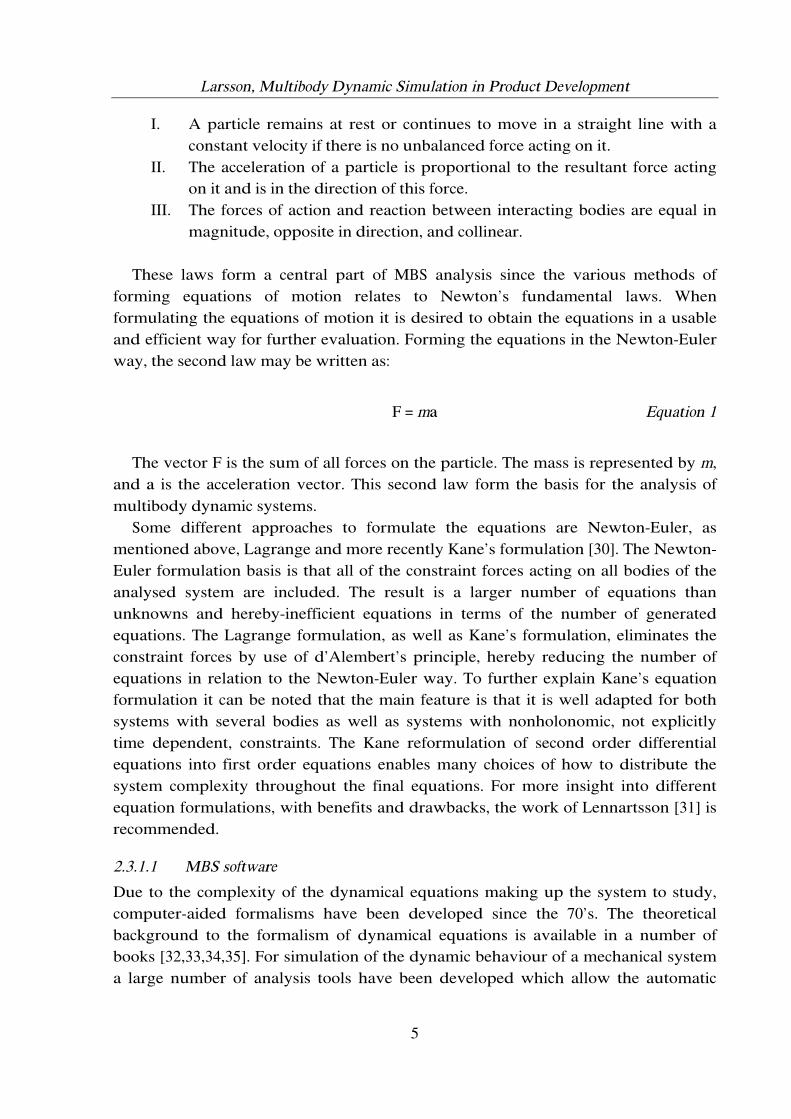
These laws form a central part of MBS analysis since the various methods of forming equations of motion relates to Newton’s fundamental laws. When formulating the equations of motion it is desired to obtain the equations in a usable and efficient way for further evaluation. Forming the equations in the Newton-Euler way, the second law may be written as:
F = ma Equation 1
The vector F is the sum of all forces on the particle. The mass is represented by m, and a is the acceleration vector. This second law form the basis for the analysis of multibody dynamic systems. Some different approaches to formulate the equations are Newton-Euler, as mentioned above, Lagrange and more recently Kane’s formulation [30]. The Newton-Euler formulation basis is that all of the constraint forces acting on all bodies of the analysed system are included. The result is a larger number of equations than unknowns and hereby-inefficient equations in terms of the number of generated equations. The Lagrange formulation, as well as Kane’s formulation, eliminates the constraint forces by use of d’Alembert’s principle, hereby reducing the number of equations in relation to the Newton-Euler way. To further explain Kane’s equation formulation it can be noted that the main feature is that it is well adapted for both systems with several bodies as well as systems with nonholonomic, not explicitly time dependent, constraints. The Kane reformulation of second order differential equations into first order equations enables many choices of how to distribute the system complexity throughout the final equations. For more insight into different equation formulations, with benefits and drawbacks, the work of Lennartsson [31] is recommended.
2.3.1.1 MBS software
Due to the complexity of the dynamical equations making up the system to study, computer-aided formalisms have been developed since the 70’s. The theoretical background to the formalism of dynamical equations is available in a number of books [32,33,34,35]. For simulation of the dynamic behaviour of a mechanical system a large number of analysis tools have been developed which allow the automatic

Larsson, Multibody Dynamic Simulation in Product Development
6
formulation and solving of the equations of motion by the computer for many types of mechanical systems. The codes available show different capabilities: generation of equations of motion in numerical or symbolic form, some of them provide numerical integration and simulation codes. Moreover, some software systems provide graphical data input, graphical animation capabilities, CAD connectivity and signal data analysis. Computer code guidelines for simulation of multibody system dynamics are given in [36,37]. Mechanical engineering simulation software with CAD/CAM integration, like ADAMS [38] and DADS [39] are commercial and has been around since the 70’s. They form Newton-Euler or Lagrange equations of motion and integrate them numerically for given initial conditions. Other software suites are Pro/MECHANICA [40] and Working Model [41], where Working Model provides a more intuitive modelling environment. The above systems have the advantage of the possibility to visualise the calculated motions, giving a better understanding than from studying time histories. Specialised software like ADAMS/CAR [38] (among other ADAMS software modules), SIMPACK [42], SOPHIA [9], AUTOLEV [43] (bot SOPHIA and AUTOLEV are based on Kane’s formulation), GENSYS [44], DYMOLA [45] and MathModelica [46] also exists (the last two approaches facilitates the object oriented modelling language MODELICA [47]). These tools have the advantage of being highly flexible for the user requiring more advanced modelling possibilities, or direct equation control. Yet, they are more complex for the design engineer to handle since they are targeted to specific markets and applications. AutoSim [48] is a software package for generation of multibody system equations in symbolic form, combined with numerical integration possibilities as well as Fortran or C code generation. A more detailed summary of commercially distributed computer codes is available in the Multibody Systems Handbook [49].
2.4 Product structuring
The area of product structuring when developing products is also of interest today. This since industry has to arrive at a product design that has been systematically optimised in order to meet customer needs and still satisfy a large market variety. This applies to products for mass customisation but also to products with lower volumes. One proposed method for dealing with the above issues is to use a modular approach in the development of the products. This since the modular approach with building blocks, modules, claims to give reduced lead-time, improved quality, high flexibility as well as retaining low costs [50,51,52,53,54]. By using work made in this area and apply it to the area of simulation, modelling benefits can be achieved since simulation models can be reused. Comprehensive work in this area is performed by [55,56,57,58]. Business and technical aspects in product modularisation are topics discussed by Blackenfelt [59]. Structuring products into modules with the help of the Modular Function Deployment, MFD, method is described by Erixon [60]. Sellgren

Larsson, Multibody Dynamic Simulation in Product Development
7
[61] introduces a modular methodology to product data management, CAD and finite element modelling.
2.5 Application areas
The work performed during the development of this thesis spans over different product applications. Efforts in simulation have been made within pantograph dynamics, hydraulic rotators, combustion engines, variable valve techniques, automotive dynamics and automotive vehicle suspension dynamics, according to examples in Figure 1.
Figure 1. MBS simulation model of vehicle suspension used in Paper F and CAD model of hydraulic rotator used in Paper E.
The area for these applications is however all within vehicle system dynamics. To enlighten the reader of the application example used in a major part of the appended papers, namely thesis Paper A-C, a short introduction to pantograph/catenary system dynamics is given below.
Pantograph/catenary system
As railway companies strive for a higher top speed of the electric trains, the problem of quality in the current collection becomes increasingly important. The overhead power system supplying electricity to a train consists of the pantograph current collector and the overhead line equipment according to Figure 2.
Figure 2. A train with its pantograph/catenary equipment.
The catenary system consists of a contact wire supported by droppers, which are suspended from a catenary wire according to Figure 3. The catenary wire is linked directly to the support poles, while the contact wire is linked to the support poles via

Larsson, Multibody Dynamic Simulation in Product Development
8
steady arms. The contact wire is staggered from side to side in a horizontal plane to distribute the wear on the carbon collector strips of the pantograph.
Figure 3. A simple ST15/15 catenary system.
The pantograph mechanism is mounted on the roof of the train. The essential features of the pantograph are the head assembly and the variable-height frame assembly, see Figure 4. The frame assembly raises the head assembly into forced contact with the contact wire.
Figure 4. The Schunk WBL88/X2 pantograph solid model.
The head assembly consists of two carbon collector strips and a frame. The strips are connected to the frame via leaf springs and rigid links at each end according to Figure 5.
Figure 5. Subsystem of head assembly.
The pantograph and the catenary system are coupled via the contact force and they form a system that can oscillate. The maximum speed of the train is often limited due to increased dynamic effects in the overhead power system. The dynamic effects cause variations in contact force, and for satisfactory performance, the contact force must neither be so low that contact is lost nor so high that excessive movement, wear or mechanical damage occurs. The simulation of pantograph/catenary system is discussed with different aims and objectives in Paper A, B and C.
Head assembly
Frame assembly
Larsson, Multibody Dynamic Simulation in Product Development
9
3 Problem formulation
3.1 Observations
There are some main problems identified leading to the research problem formulation when discussing MBS in product development.
Generic methodology for MBS simulation of mechanical systems
In the area of simulation of dynamic behaviour of mechanical systems numerous of analysis tools have been developed which allow the automatic formulation and solving of the equations of motion by the computer for many types of mechanical systems. In order to make it possible for a design engineer, and not only for a specialist in dynamics, to use simulation methods for the efficient development of dynamic systems the complexity of the procedure for using them must be reduced. This implies the identification and development of a generic MBS methodology.
Efficiency of MBS methodology
When the MBS methodology is identified it is important to identify actions to make the process more efficient. This includes an understanding of the different MBS simulation phases and the topic of dealing with the steps in a correct way. The efficiency is related to a thorough understanding of the MBS process.
Complex models connected to the creator and location
The simulation models often get very complex and are connected to the creator who almost always is an expert in simulation of dynamic systems. This makes it hard for a design engineer, or someone else in the company, to use the model since his knowledge of the complete model must be related to the creator of the model. This also creates a problem in terms of globalisation of companies, i.e. distributed organisations, since parallel product development of the modelled systems are restricted by the local simulation departments.
When to use the methodology of dynamic analysis
The analysis might be carried out fairly late in the design procedure today, but it is rather the contrary that would make simulations really beneficiary. The intention is to, at some extent, go from simulation verified design to simulation driven design where MBS simulation is a natural part of the development process.
Development of computer hardware and software
The life cycle of computer hardware and software is short, and an approach to MBS support methodology cannot depend on specific computer implementations, i.e. approaches must be hardware independent.

Larsson, Multibody Dynamic Simulation in Product Development
10
3.2 Aim and scope of research work
A computer-aided concurrent engineering system might look according to Figure 6. The dashed line represents the focus area in this project, simulation of multibody dynamic behaviour.
Figure 6. The information flow in a computer-aided concurrent engineering system [62].
The different tasks in the engineering system are performed at different stages of the development process although some tasks might be performed concurrently in an iterative process. As seen, the objectives in this work are in modelling and simulation of product performance. The goals of the research are in line with the ENDREA research proposal [63] with regard to the area of “Modelling, synthesis and analysis methods” in particular addressing the following two areas;
- Methodology for modelling and simulation of dynamic systems. - Improve the understanding of MBS simulation in product development.
3.3 Research question
The research question guiding this work is formulated as:
How can structuring of simulation models and their usage be made in order to make the process of computer-aided simulation of dynamic mechanical systems more efficient and usable in the product development process?
The work concentrates on efficient development of multibody dynamic systems. Focus is on clarification of the MBS process and usage of a modular MBS approach. The advantage of this approach is that the simulation model consists of modules that are separated with specified interfaces, which makes it possible to replace an old

Larsson, Multibody Dynamic Simulation in Product Development
11
module with a newly developed one without changing the individual specification of the other modules. This creates the possibility to test different design solutions with as little effort as possible. The modular approach gives the opportunity to reduce time in the product development process and will make it easier to develop new generations of products, as well as reduce time in continuous development.
3.3.1 Industrial and academic importance
The possibilities and advantages of computer aided simulation of mechanical systems are not fully exploited in industry today and the industrial importance of achieving a more efficient simulation process will lead to:
- Enhanced possibilities to analyse more design solutions. - Improved possibilities to simulate more situations. - Better quality through better base of decision. - Shortened product development time through less product design iterations. - Possibilities to perform simulation driven rather than simulation verified
design in product development. Scientifically, achieving the research goal will result in:
- Identification of MBS methodology. - Identification of phases that influence the efficiency of the MBS simulation
process. - Proposal for how the structuring of the MBS simulation process in product
development can be made. - Ability of implementation in other simulation processes of the product
development process. The research in this project is based on existing theories concerning product development processes and methods, concurrent engineering and multibody dynamics simulation. Two main themes guide the development of this project;
The approach has to be hardware independent
The approach is to make the process of multibody dynamics more efficient by structuring simulation models and the method for usage in product development. Previous work to make simulation more efficient has concentrated on developing faster calculation methods. The methods to use must stand above computational problems such as processor speed.

Larsson, Multibody Dynamic Simulation in Product Development
12
The approach has to be demonstrated and evaluated in a realistic environment
Perform case-based studies of how computer aided simulation of dynamic behaviour is used within industry today applied to relevant applications. Use experiences from current process for multibody dynamic simulation. Apply experiences from structuring of products, i.e. modularisation techniques. Develop refined MBS methodology and implement into prototype system in cooperation with industry.

Larsson, Multibody Dynamic Simulation in Product Development
13
4 Multibody dynamics in the product development process Traditionally, mainly large companies with special analysis departments have used simulation in their development of products. These simulation verified products are typically of very high technical level. Due to the rapid development of digital computers, and since the techniques for modelling and simulation are becoming mature, a broader spectra of industrial companies are eager to use and implement them as tools into their development processes.
4.1 Mechanical system development
The development of a product is often an iterative process, both the whole process as well as underlying sub-processes. There are different aspects on MBS simulation when developing a product regarding if it is a new mechanical system, original design, or if it is a redesign of an existing product, continuous design.
4.1.1 MBS in original design
When performing original development of a mechanical system it is advantageous to perform MBS simulations in order to:
- Be able to make well-founded decisions early in the product development process.
- By performing early analysis it is possible to try out basic design concepts without extensive prototype design.
- If available, earlier generations of similar simulation models can be reused as base.
- Give the designer a possibility to test more ideas in shorter time.
- With a digital prototype, or model, of the system it is easy to make changes.
- Changes in physical prototypes is time and resource consuming - Possibility to choose from more concepts, which gives a better base for
decisions and hereby a possibility to a better product solution. - Parametric models can be used for design studies where simulations
can be performed automatically until a desired target value is reached. - Separate the different design solutions.
- One must clearly define the design, the assumptions and the evaluation criteria. By having to do this, the design originality is clearly stated.
- Understand the product behaviour and how it is affected by different factors
before it is manufactured.

Larsson, Multibody Dynamic Simulation in Product Development
14
- If the ready-to-manufacture prototype is subjected to simulations corresponding to physical conditions, sound product knowledge can be achieved.
- Discover unexpected behaviour.
- With physical prototype testing being more expensive, at the same time a tedious work, the approach of using simulations would increase the possibility to find unwanted or unexpected product behaviour.
- Be sure that the product fulfils the demands.
- Virtual testing of the product specifications would reveal if customer requirements were missed in terms of wanted product performance.
4.1.2 MBS in continuous development
When dealing with continuous development of a mechanical system, MBS simulations are advantageous in order to:
- In order to improve the product. - Many products have a long life cycle. There are financial incitements to
continuously improve their performance. The issue is to use existing designs as far as possible as well as having well-motivated arguments for making changes.
- In order to optimise design solutions regarding for example fuel
consumption, weight and risk for accidents. - Here, the earlier product versions, and simulation models, are very
useful when optimising parameters for the next product generation. Reuse of earlier models is crucial. Virtual prototype testing is a safe way to examine possible dangerous parameter set ranges.
- To estimate the product sensitivity to changes caused by, for example,
weather, wear and ageing. - Performing parameter changes corresponding to upcoming life cycle
situations will increase total quality.
- To test unrealistic or dangerous situations as for example high speed running with trains.
- The risk of product failure and hereby following consequences as person injuries, material damages, delays in traffic, among others, makes it very expensive to test new ideas. Simulation ought to be used in order to make a reasonable judgement of the product performance in
Larsson, Multibody Dynamic Simulation in Product Development
15
advance. The physical system parameters are used as input for the simulation model.
- To understand the product behaviour and factors that affect the behaviour at
controlled repeated conditions. - In full-scale field experiments many parameters vary at the same time,
for example wind loads, temperature, air humidity, vehicle conditions and infrastructure. By developing models and study effects of changes in different parameters during controlled conditions one can locate resources where they are most beneficial.
4.2 Simulation processes in product development
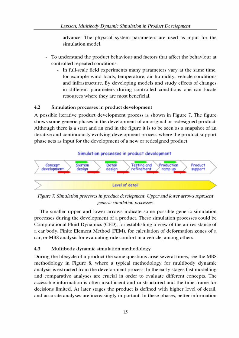
A possible iterative product development process is shown in Figure 7. The figure shows some generic phases in the development of an original or redesigned product. Although there is a start and an end in the figure it is to be seen as a snapshot of an iterative and continuously evolving development process where the product support phase acts as input for the development of a new or redesigned product.
Figure 7. Simulation processes in product development. Upper and lower arrows represent generic simulation processes.
The smaller upper and lower arrows indicate some possible generic simulation processes during the development of a product. These simulation processes could be Computational Fluid Dynamics (CFD), for establishing a view of the air resistance of a car body, Finite Element Method (FEM), for calculation of deformation zones of a car, or MBS analysis for evaluating ride comfort in a vehicle, among others.
4.3 Multibody dynamic simulation methodology
During the lifecycle of a product the same questions arise several times, see the MBS methodology in Figure 8, where a typical methodology for multibody dynamic analysis is extracted from the development process. In the early stages fast modelling and comparative analyses are crucial in order to evaluate different concepts. The accessible information is often insufficient and unstructured and the time frame for decisions limited. At later stages the product is defined with higher level of detail, and accurate analyses are increasingly important. In these phases, better information

Larsson, Multibody Dynamic Simulation in Product Development
16
is often available in form of experimental data from prototype testing and better product knowledge. This makes it possible to verify the developed simulation models. After this verification, the simulation model can be used to predict, if used in a correct way, the behaviour in other situations than the experimentally tested ones.
Figure 8. Multibody dynamic simulation in different parts of the development process.
The MBS methodology is similar independent of the level of detail of the model and the chosen simulation method since the questions to ask in the MBS process do not change. This makes it easier to reuse earlier work and easier to document the performed work. The products are often complex and include many degrees of freedom as well as non-linear characteristics. This implies that it only occasionally is possible to find analytical solutions to the equations of motion. Often, one must use numerical experiments where the motion of the developed models is calculated for different situations. It is often suitable to connect the definition of the dynamic system to a CAD-tool, where it is relatively easy to define geometry, calculate mass and inertia, position of joints and loads among others. 3D CAD models are also suitable for investigation of aerodynamic forces, for visualisation of the design, and for animation of dynamic performance.
The MBS methodology consists of the following main steps, see Figure 8:
1. Problem formulation 2. Definition of idealised model 3. Development of computer model 4. Formulation of system equations 5. Equation solving 6. Result post processing 7. Evaluation and conclusion
Each step will be further discussed and exemplified, with relation to appended papers, below.

Larsson, Multibody Dynamic Simulation in Product Development
17
4.3.1 Problem formulation
This step concerns setting the boundaries and targets of the problem to solve. Definition of physical effects to include, or exclude, in the simulation procedure is desired. Without proper problem definition it is very hard to evaluate the results since there is nothing to relate the results to. A problem definition, regarding the functional behaviour or performance, should be included in the original problem definition developed when using, for example, Quality Function Deployment (QFD) or other design theories and methodologies. Important is to quantify the targets to achieve, to avoid misinterpretation. Targets could for example be force levels, torque or accelerations. This phase is the link to the previous activities in the product development process. In paper A, as an example, the problem formulation is limited to the study of changes in head suspension key parameter, while the parameters influence on the dynamic effects of the whole pantograph is desired, see CAD model of physical problem visualisation in Figure 9.
Figure 9. Pantograph current collector.
In paper B, the system is limited to the study of carbon collector strip suspension parameters, with no regard to the total pantograph behaviour; see system description in Figure 10.
Figure 10. Carbon collector strip suspension of pantograph.
Head assembly
Frame assembly

Larsson, Multibody Dynamic Simulation in Product Development
18
Important is to define:
- Technical problem to solve. - Limitations of system to investigate. - System components.
When the MBS simulation sequence is performed it is with respect to the problem definition that the simulation results should be related. If, at any time, the problem definition is changed, the simulation sequence has to be reinitiated; else the results will have little or no relation to the defined problem.
4.3.2 Definition of idealised model
After the problem is identified and the system components are defined, the actual model has to be derived. The model should be simple enough, yet describing the problem to be solved. Including steps are:
- Collecting relevant system data - Model parameters - Choice of solution method
Relevant system data includes component couplings to each other. In case there is a physical system to study this is performed with relative ease, otherwise it can be a tedious task to determine component relations. It is important to always have the problem formulation in mind when making choices, such as parameter resolution among other choices. Model parameters typically include mass, centres of gyration, component properties such as damping and stiffness as well as existing system forces. The help of experiments can make system parameter identification easier. In Paper A and B stiffness and damping parameters in the head suspension were derived from experimental measures and processed with MATLAB [64], see Figure 11.
Figure 11. Examples of experimental results.

Larsson, Multibody Dynamic Simulation in Product Development
19
The choice of solution method is based on first having an established understanding of available information. Then it is possible to decide the solution method to go on with. In the case of MBS one can choose between, for example, hand calculation, generation of equations to be solved by computer and development of 3D computer models in solid modelling software. The final choice of solution method is made after comparison with the initial problem formulation and required level-of-detail of the results.
4.3.3 Development of computer model
Depending on what solution method that is chosen, different computer models may be developed. A more detailed model is often connected to a less flexible solution method, while parameter data for a model that resembles the physical design might be easier to determine. Some simulation models related to the work in Paper A-C are shown in Figure 12.
Figure 12. Different level-of-detail simulation models within pantograph/catenary simulation.
Some motives for choice of simulation model can be:
- Access to information - Wanted result accuracy - Allowed simplifications - Available resources
- Time, money and personnel The simulation model’s level-of-detail can range from simple one-degree-of-freedom (DOF) models to complex three-dimensional multi-DOF solid models, according to pantograph/catenary simulation models in Figure 12. When building the more complex, i.e. 3D, models it is often suitable to connect the definition of the dynamic system to a CAD-tool, where it is easy to define geometry, calculate mass and inertia, position of joints and loads among others. Three-dimensional CAD models are also suitable for visualisation and revising of the

Larsson, Multibody Dynamic Simulation in Product Development
20
design at later stages in the process. A suitable way for enhancing the modelling phase is to use macros, native command sequences, to automate the model set-up. This technique is used in Paper F. The modelling method of MBS is based on a finite set of elements such as:
- Gravity - Rigid bodies and particles - Bearings, joints and supports - Springs and dampers - Active force and position actuators
A data model has been defined as a standardised basis for multibody systems [65,66]. In short, the following assumptions are valid:
1. A multibody system consists of rigid bodies and ideal joints 2. The topology of the multibody system is arbitrary. Chains, trees and closed
loops are admitted 3. Joints and actuators are summarised in open libraries 4. Subsystems may be added to existing components of the multibody system
A global data model according to Figure 13 is shown below giving basic orientation in mechanical system simulation in a concurrent engineering environment.
Figure 13. Global data model for mechanical system simulation [65]

Larsson, Multibody Dynamic Simulation in Product Development
21
Multibody systems, as defined, is characterised by the class mbs and consists of an arbitrary number of classes part and interact, according to Figure 14. The class part describes rigid bodies. Every part is represented by at least one body-fixed frame, mass, centre of mass and inertia.
Figure 14. MBS system to be represented by the data model [66]
The interactions, or couplings, between the different parts may be realised by a joint, a force actuator or a sensor resulting in the classes joint, force or sensor. The class interact is characterized by two types of information: the frames to be connected and the connecting element itself. Exemplifications of some common joint types are seen in Figure 15.
Figure 15. Library of standard joints.

Larsson, Multibody Dynamic Simulation in Product Development
22
While methods for analysis of elastic bodies are beginning to emerge, the rigid body is at the heart of most methods and applications. A rigid body is assumed to not undergo deformation when exposed to force fields. This is of course a simplification since no material can be applied with load changes without deforming. Nevertheless, for a large number of cases, considerable insight can be gained by modelling systems of rigid bodies. In the thesis work the software tools MATLAB, SOPHIA (in MAPLE [67]), I-DEAS, ADAMS and WORKING MODEL have been used, together with in-house codes, to build simulation models of varying level-of-detail.
Design of computer experiments
There are considerations in terms of analysis objectives; if the analysis objective is to simulate a single model parameter set in order to establish system performance for that specific set or if the objective is to analyse dynamic behaviour due to changes in system parameters. The latter topic is where computer simulations have proven to be very beneficial. There are different methods of parameter investigation, such as design study or design of experiments (DOE). The design study is related to investigation of parameter changes and the effect the changes have on the system behaviour while the DOE is related to the understanding of system sensitivity to parameter changes, an area closely related to robust design. Performing DOE is important when the analysis objective is to find some kind of optimal solution. When the optimisation has been performed a DOE can be performed to study the sensitivity and hereby the outcome of difference in parameters that effect the design and the design robustness. The ranges of the sensitive parameters could for example be related to the manufacturing tolerances. If no notice is taken to possible parameter variation this could result in product failure in terms of the defined product performance. DOE is to be considered as a set of procedures and statistical tools for planning experiments and analysing the results. Traditionally, DOE was developed for experimental testing of physical prototypes but it works just as well with virtual prototypes. For simple problems the investigation of system behaviour is typically performed via a combination of intuition, trial-and-error, and brute force. This is not a recommended, however often used, way of pursuing the results. With increasing number of system variables and a need to establish variables dependence and relations, DOE quickly becomes necessary. A typical DOE process includes:
- Purpose of experiment
- Identification of parameters which have most effect on the system - Choice of factors
- Develop method to measure system response - Determine parameter ranges and plan a set of runs with parameter variation

Larsson, Multibody Dynamic Simulation in Product Development
23
- The combination of runs is known as the design - Execute the run schedule
- Record output - Analyse the outcome in design objective
- Determine the factors with largest effect on the target objective Experiments with few parameters, i.e. two or three, might only require some five to ten runs. As the number of investigated parameters increase the number of runs increases as well, some hundred runs are not uncommon. A well-planned DOE is critical to keep computational efforts to a minimal and to ensure success in the experiment. A successful experiment should consist of as few runs as possible, yet contain enough information to draw conclusions of the system behaviour. The best set of parameters, best design of the DOE, depends of a number of factors such as chosen parameters, number of runs, assumptions made in the process and the overall formulation of the process. The chosen parameters of a design study are collected in a design matrix. Typically, a design matrix consists of initial values and the allowed range of values. The range is often oriented in an indexed way where the index centres on zero. This would mean, that for a two-level value the design matrix would consist of the values –1 and +1, for a four-level matrix: -2, -1, +1, +2, and so on. In terms of choosing the number of levels for a parameter and plan number of runs there are some commonly known design methods:
- Full factorial
- Most comprehensive - Use all of the possible combinations of levels - Total number of runs: mn where m = levels and n = parameters - Only practical for few parameters
- Fractional factorial - Subset of full factorial - Reduced-factorial design method - Number of runs set by user
- Box-Behnken - Uses points on planes of a design space, i.e. a cube - Relatively few trials - Requires a parameter to have three levels
Further information of design of computer experiments can be found in [68,69]. Lawson and Erjavec [70] examine modern statistics for engineering in a thorough way. The actual performing of the DOE analysis work can be done in different ways;

Larsson, Multibody Dynamic Simulation in Product Development
24
simulation control scripts, routines in commercial software or by development of own simulation codes. The methodology of factorial design has been used in Paper A with parameters and maximum and minimum levels according to Table 1.
Table 1. Range of head assembly subsystem parameters.
Parameter Min ( - ) Max ( + ) Viscous damping, C [Ns/m] 1 10 Spring stiffness, K [N/m] 950 1250 Friction, F [N] 0.1 1 Distance to end stop, S [m] 0.03 0.04
The factorial design result in Table 2 show the specific runs with the parameter levels, - or +, given to each parameter and parameter combination.
Table 2. Factorial design results.
C K F S CxK CxF CxS KxF KxS FxS CxKxF CxKxS CxFxS KxFxS CxKxFxS Values
1 - - - - + + + + + + - - - - + 28
2 + - - - - - - + + + + + + - - 17
3 - + - - - + + - - + + + - + - 28
4 + + - - + - - - - + - - + + + 16
5 - - + - + - + - + - + - + + - 16
6 + - + - - + - - + - - + - + + 14
7 - + + - - - + + - - - + + - + 14
8 + + + - + + - + - - + - - - - 13
9 - - - + + + - + - - - + + + - 33
10 + - - + - - + + - - + - - + + 17
11 - + - + - + - - + - + - + - + 55
12 + + - + + - + - + - - + - - - 22
13 - - + + + - - - - + + + - - + 17
14 + - + + - + + - - + - - + - - 15
15 - + + + - - - + + + - - - + - 22
16 + + + + + + + + + + + + + + + 17
Values -10 4 -11 6 -3 8 4 -3 5 -3 2 -2 3 -2 2
Besides the example given above, the work in Paper B, E and F has also been carried out using different types of analysis planning. In particularly, the analysis work of Paper B, concerning non-linearities and chaos, required some tedious analysis planning since the procedure of result interpretation with bifurcation diagrams and Poincaré maps put requests on the number of runs to be performed in order to produce plots of the right level of detail. The design study and DOE work in mentioned papers have been invoked in MATLAB, ADAMS, Working Model and also in simulation scripts developed throughout the thesis work.

Larsson, Multibody Dynamic Simulation in Product Development
25
4.3.4 Formulation of system equations
The formulation of system equations used to be a difficult and time consuming task, and still is, depending on approach. Many types of MBS simulation software, i.e. ADAMS, DADS, automatically derive the equations of motion and solve them for given initial conditions. However, sometimes it is required to have more control over the equation generation. This could be the case when need is for highly efficient computation and model control, such as real-time simulation, hardware-in-the-loop (HIL) simulation discussed in Paper D, or when there is a need for manually derived equations for numerical integration in mathematical software. As an exemplification, the equation of motion for the pantograph system studied in Paper B is given below. The physical system representation is given in Figure 10.
Equation 2 The earlier MBS process levels have been tightly connected to what is known as the physical model description level [71]. This equation-oriented level is known as the mathematical description level since models are revised and used in their equation form.
4.3.5 Equation solving
The actual solving of equations can be made on different levels as well. In commercial dynamic analysis packages, the solving of equations in the time domain can be performed automatically with little or no interaction needed from the user. Usual parameters to deliver as input are simulation step size and simulation end time. When working with the equations in a more direct way it is useful to perform the integration with the help of scientific software, for example MATLAB, to arrive at the results with given equations-of-motion. In Paper B, E and F, MATLAB has been used to integrate the derived equations of motions. When dealing with numerical integration there are many methods available [72], two classes are Runge-Kutta and predictor-corrector methods. In terms of symbolic manipulation with computers, Computer Algebra Systems (CAS), systems have been around since early computational support days. CAS systems are intended for symbolic manipulation of expressions, and not floating point numeric. Although the simulation tools are proven to be of great help in numerical integration there are still issues with numerical errors, or instability. These issues often result in the failure of a simulation. It is a time consuming task to develop a functional simulation model in terms of not failing when submitted to the solver. There are issues with choice of solver, settings of solver, model parameters and

Larsson, Multibody Dynamic Simulation in Product Development
26
system components. There are different methods for solving the differential and algebraic equations (DAE) generated. Two basic types of algorithms to perform the numerical integration are:
- Stiff methods
- Implicit, backwards difference formulations (BDF) to solve the DAE - Non-stiff methods
- Explicit formulations to solve ordinary differential equations (ODE) obtained from DAE by coordinate partitioning methods
ADAMS has been used extensively throughout this work and in the ADAMS/Solver there are four stiff integrators and one non-stiff integrator implemented, as of version 10.1:
- Gear (GSTIFF) - Modify Gear (WSTIFF) - DASSL (DSTIFF) - SI2 (GSTIFF) - Adams-Bashforth-Adams-Moulton (ABAM)
To minimise the number of analysis failures it is important to have control over the settings in the different integrators. This information is often available in the reference manuals of the software and should not be neglected for successful solving of systems and equations. It is also important to consider the relationship between step size and analysis time when performing the analysis since this highly affects the resolution of the output results.
4.3.6 Result post processing
When the modelling and computer analysis procedure is finished a crucial step surfaces: the post processing. The ability to post process in a correct way is very much up to previous experience of the user, but some pointers can be made. When using commercial software for the analysis of complex mechanical systems, the number of possible results to choose from is very big. For a simple system with few parts dozens of result components exists to be investigated. Components like displacements, velocities, accelerations and forces in X-, Y- and X-directions together with torque components. The results can be evaluated in many different ways; direct scalars, different combinations of plots and curves, animations and interactive animations, to mention a few. Depending on type of problem different types of evaluation is beneficiary. A brief introduction to general post processing techniques are given, following is a chapter more related to the analysis of non-linear systems.

Larsson, Multibody Dynamic Simulation in Product Development
27
The simplest way of result investigation is perhaps when a result is asked for at a given time configuration. The result is then simply the value for the corresponding time. If the time is extended to withhold the total simulated time sequence the result would be shown as a curve in a plot. In Figure 16, a result containing the simulation time (1.2 sec) and the resulting torque (in this case dimensionless) for two different parameter sets. It is easy to evaluate the direct effects of a parameter change.
Figure 16. Simulation result form Rotator simulation in paper E.
The use of animations as a way to interpret results is very common in MBS simulation since this is a good way to get an image of how the studied system behaves. The use of animation implies that geometric information is available, often as solid models. The resulting part motions are then mapped onto the solid models to create animation sequences for visual evaluation. The animations can be visualised locally or exported as movie files.

Larsson, Multibody Dynamic Simulation in Product Development
28
Figure 17. Rotator animation of hydraulic behaviour, Paper E, and pantograph dynamic behaviour animation, Paper A-C.
The animation windows shown in Figure 17 are non-interactive animations, movie files. Interactive animations, exported from the created animation sequence, can also be used. VRML (Virtual Reality Modelling Language [73]) animation is one way to let the user interact with the motion result in 3D, using web techniques. This possibility has been used in Paper F, according to Figure 18.
Figure 18. Interactive VRML visualisation in a web browser.
The possibility of raw data output is also important. This since the derived analysis results might be used later in the development process for purposes not thought of at the stage of post processing. Raw data can then be used as input to other simulation processes, input to manufacturing equipment control, input to a redesign MBS process or as input to an optimisation algorithm.

Larsson, Multibody Dynamic Simulation in Product Development
29
4.3.6.1 Non-linear systems
Dynamic behaviour of non-linear, or chaotic, systems is a more complex issue to examine and analyse than linear systems. A brief introduction to the result analysis in terms of non-linear systems is given here. Linear systems are commonly solved by linear superposition of solutions, a method that is not generally recommended for systems containing non-linear characteristics. The developed products of today are highly complex, see Paper D, and often require non-linear theory to explain upcoming dynamic behaviour. It is then important to be able to discover and deal with non-linear behaviour when post-processing analysis results from such a system. In paper B, the non-linear pantograph suspension is excited with a harmonic excitation. Results are according to Figure 19 on next page.

Larsson, Multibody Dynamic Simulation in Product Development
30
Figure 19. Time histories and phase plane portraits from Case 1 in Paper B. Dot-dashed line represents excitation force and solid line represents resulting displacement in left figures.
The figure shows time histories and phase plane portraits. An explanation is in place:
Time histories
A time history is a plot showing how a value varies with time. The value can be displacement, velocity or for example acceleration. The time history gives an indication of the studied system behaviour. If the appearing pattern seems regular

Larsson, Multibody Dynamic Simulation in Product Development
31
the system may be periodic, else it can have a long period or be chaotic. Time histories are a very common way to post process simulation results. However, this representation is difficult to use if the period is long and the behaviour varies a lot as a function of time. With relation to the results in Figure 19 the time histories show that f=6.00 Hz indicates periodic motion together with f=3.20 Hz.
Phase plane portraits
A phase plane plot consists of plotting the velocity against the system displacement. This is a very good method to distinguish periodic motion of different order from nonperiodic or chaotic motion. Closed curves, or trajectories, in the phase plane will appear for any repetitive motion. Nonperiodic motions occur as infinite periods with tendency of filling up the phase plane. Since the motion is restricted within an area of the phase plane the motion can be represented for a much longer time interval than with a time history. With relation to the results in Figure 19 the phase planes show that f=6.00 Hz is a periodic motion together with f=3.20 Hz (subharmonic of order 2) while f=2.80 Hz indicates chaotic behaviour. Phase plane portraits can, as viewed, be used to clarify time histories and hereby increase the understanding and interpretation of the system response. To further investigate possible non-linear or chaotic behaviour the use of Poincaré maps and Bifurcation diagrams appear as a solution.
Figure 20. Poincaré diagram from paper B. Case 1 and excitation frequency of 2.80 Hz.
Poincaré map
A Poincaré map is a modified type of phase plane portrait where the state variables are plotted at discrete times. State variables like velocity and displacement are sampled once during each period of the excitation period. If the response is periodic with the same period as the excitation the points will converge to a point. If the response is periodic with a period that is a multiple of the excitation period, the

Larsson, Multibody Dynamic Simulation in Product Development
32
result will be a set of points. If the map shows a fractal like structure with an uncountable number of points, this implies chaotic motion. With relation to the results in Figure 20 the Poincaré map show that the excitation frequency f=2.80 Hz introduces chaotic behaviour. The typical shape of the plot is known as a chaotic attractor, typical for impacting systems.
Bifurcation diagram
Bifurcation diagrams are a powerful geometric representation of the system response. One can plot the impact velocity, Figure 21 a, or the Poincaré velocity, Figure 21 b, as a function of system parameters, in this case against the frequency. Bifurcation diagrams are valuable when the system behaviour is complex and there are large amounts of pictures (time histories, phase planes and Poincaré maps) even when a small parameter space is investigated. When the diagrams lose continuity, this indicates chaotic or quasiperiodic motion and further investigation should be performed, as for example the cell mapping approach [74].
Figure 21. Bifurcation diagram from paper B. Left (a) show impact velocity, right (b) show Poincaré point velocity for Case 1.
With relation to the results in Figure 21 the interpretation of the diagrams can be as follows. From 2 to 2.87 Hz the response is periodic with the same period as the excitation. The mass starts to impact the lower stop when the excitation frequency is increased to 2.88 Hz. The response is subharmonic with a period two motion up to 3.29 Hz where the response becomes periodic with the same period as the excitation again. The response continues to be a period one motion until 3.90 Hz, where it becomes subharmonic with a period of three. The mass is now impacting with both end stops of the systems. At 3.94 Hz the response becomes subharmonic of period two. At 4.30 Hz the response is a period four motion. Between 4.34 and 4.49 Hz the response is irregular. At 4.50 Hz the response is subharmonic again with a period of two. Finally, the response is of period one from 4.51 to 6 Hz. The chaotic attractor shown in Figure 20 has characteristics typical for impacting systems, i.e. the apparent disconnectedness of the attractor as well as the sharp

Larsson, Multibody Dynamic Simulation in Product Development
33
corners. These are signs of the mass undergoing low velocity grazing impacts that causes the system to become unstable. This is also visible in the bifurcation diagrams shown in Figure 21. When low velocity impacts occur in the impact velocity diagrams, irregular motion is visible in the Poincaré point velocity diagrams.
4.3.7 Evaluation and conclusion
When the whole process of problem formulation, modelling, analysis and result interpretation is complete the last step is to evaluate to given results. The evaluation of the system behaviour has to be compared with the initial problem specification. If the problem is solved, then go ahead with the next step of the development process. If the problem is not solved to satisfaction it is important to find out what is wrong and maybe iterate the MBS procedure once again. Some measure of robustness in the analysis procedure is also wanted. It is important to understand the limitations that are made during the procedure. What effects have been included, or excluded, what is the uncertainty of the results?
4.4 MBS process reflections
The above-described MBS process has its origin in literature combined with findings from the MBS modelling performed in the thesis work. It can work as a guide for planning and performing MBS simulation in product development. The steps of equation generation and solving in the MBS process are often computerised while the other steps still require human effort. Naturally, this process is applied differently depending on company and personnel situation. Documentation when performing the steps above is important, both in terms of creating the opportunity to reproduce the specific results of each step and in terms of having the process documented if redesign is necessary.
Process efficiency
In terms of the described MBS process, there are some reflections affecting the efficiency of the process when it is deployed. If some of these issues where solved the total efficiency of the MBS process would increase. There are issues concerning:
- Simulation model creation - Continuous documentation efforts - Connectivity to CAD software desired for geometry definition - Modularity
- Parallel development of models - Model connected to creator
- Model building experience important - Standardised data model
- STEP

Larsson, Multibody Dynamic Simulation in Product Development
34
- Data base storage - Model definition related to specific software
- Simulation model reuse - Ease of model reuse - Generic result data storage
- Simulation software - Models connected to model building software - Models not interchangeable between MBS packages - Model execution problems - Multidomain connectivity
- Different software packages simulate different physical effects - Post processing
- Information overload - Choice of result type to investigate - Choice of result component to investigate
Some of the above observations are discussed and dealt with in this thesis, other are left for future improvement. In the following chapters a modular approach to MBS modelling is discussed and exemplified. The gained knowledge of possibilities and problems are used to implement a prototype system
4.5 Modular multibody dynamics modelling approach
When simulating, for example, pantograph/catenary dynamics in the development of a current collection system it is important to consider in what way the different methods are to be used. Generally, simulation departments have simulation experts that build, simulate and analyse results of a given task received from, for example, the design department. In this way the special domain knowledge of the design department is lost since they do not perform simulations themselves. If the tools were handled in such a way that the simulation department developed a parameterised simulation model of, for example a pantograph suspension, and the suspension department designers were given this model, then they could combine their domain specific knowledge with the simulated behaviour and develop a good product. This approach would make parallel development of subsystem models, or simulation modules, possible. If the different developed subsystems then were integrated into a common simulation environment where total system simulation were performed it would be possible for the subsystem designer to see the impact of his development to the total system behaviour without having the knowledge to build the total system. Simulation models developed when working with pantograph/catenary systems might look like Figure 22.

Larsson, Multibody Dynamic Simulation in Product Development
35
Figure 22. Simulation models developed for pantograph/catenary system, Paper C.
By building the full system simulation model out of a library of subsystems many solutions would be possible. Each domain developer update their own domain library. A pantograph/catenary simulation module environment could then look like Figure 23.
Figure 23. Module system for pantograph/catenary system simulation.
When developing the simulation models it is important to define the interfaces, or boundaries, of the model. Then every simulation model can be connected to the other simulation models later on in the process. The advantage of this approach is that the model consists of modules that are separated with specified interfaces that make it

Larsson, Multibody Dynamic Simulation in Product Development
36
possible to replace an old module with a newly developed one without changing the individual specification of the other modules. This creates the possibility to test different design solutions with as little effort as possible. The modular approach also gives the opportunity to reduce time in the product development process and will make it easier to develop new generations of products. Other effects are that a design engineer and not only a simulation expert can develop simulation models and perform simulations. If the MBS process were to be redesigned in order to account for the modular development way it would look like Figure 24. The start of the process would again be the main problem formulation, leading to a modularity identification phase where the problem would be investigated for possibilities to break it down into separated simulation modules. Then the top simulation model framework would be defined together with sub module interfaces, to establish distinct module connections.
Figure 24. Modular MBS process approach.
The sub models could now be simulated, according to the existing MBS process, either in-house or distributed. The possibility of black-box simulation of sub models could be facilitated. Black-box simulation models could for example be simulation models of parts manufactured by subcontractors, where they do not want their company specific knowledge to be spread beyond control. The simulation modules can now be developed in parallel with different level-of-detail and independent of each other. Depending on the accessible information and at what stage of the development process the simulations are to be performed, different model level-of-detail is used. Module simulations can be performed as well as full simulation model investigation with the inclusion of the other modules.

Larsson, Multibody Dynamic Simulation in Product Development
37
In terms of structuring the above-mentioned models, or modules, techniques from product structuring in general is observed. Ideally, the same module structure of a product should be used within the whole company; i.e. the engineer sees the same modules as the salesman, the manufacturing engineer, the development engineer and so on. The topic of modularisation and MBS analysis is discussed in Paper E. The discussed modular MBS approach is so far valid for simulation of dynamic mechanical systems. However, the role of simulation in industry is rapidly changing to arrive at a multidomain simulation arena. This is a result of the product development where products are evolving towards more integrated systems in terms of including mechanical, electrical, fluid-power and digital computing elements. Vehicle development, like automobiles, is a typical example. These multidomain systems are commonly known as mechatronic systems. The development of these systems requires a synergetic engineering approach rather than a simultaneous engineering approach, see Figure 25, implying that the different domains no longer can be treated separately in a development process.
Figure 25. Synergetic Engineering in mechatronic design, Paper D.
It is important to relate the analysis methods for mechatronic systems to the MBS simulation methodology. In the following chapter a prototype system is discussed where the modular MBS methodology is facilitated and where control simulation is integrated in the MBS simulation of mechanical systems to create multidomain simulation possibilities.
4.6 Prototype system
Based on the proposed modular MBS approach and the need of integration of multidomain simulation, a prototype system where the presented ideas are implemented has been developed. The idea is that the system shall facilitate ideas regarding how to use the MBS methodology in product development. The application is within vehicle dynamics, a front suspension, and the possibility for an engineer, and not only a simulation expert, to perform MBS analysis is created. In the work a collaborative MBS simulation environment is proposed and developed. Based on the belief that events can be correctly understood only if observed in their natural environment, ethnographic methods have been used in order to understand and describe the engineering analysis work practice that the tool

Larsson, Multibody Dynamic Simulation in Product Development
38
is supposed to support. The simulation packages ADAMS and MATLAB are used together with database and web technologies, according to Figure 26.
Figure 26. Software tool integration in prototype system.
The collaborative tool lets the user perform simulations of systems, consisting of modules that can be distributed within company departments or externally, via the Internet, to subcontractors and suppliers. The system is hardware independent since all interactions with the system are performed via web interfaces; see Figure 27 and Figure 28, although the actual simulations are performed in a batch mode on workstations with server capabilities.

Larsson, Multibody Dynamic Simulation in Product Development
39
Figure 27. Input interface.
Figure 28. Output interface.
The prototype system acts as an exemplification of the discussed ideas and is not to be treated as a commercial system. Further work on the prototype system would include developments in the database solution, module interface specifications and the use of a standard modelling language for MBS systems. The system connects ADAMS, MATLAB and some in-house codes. The prototype system is discussed more thoroughly in Paper F.
Larsson, Multibody Dynamic Simulation in Product Development
40
5 Summary of papers
5.1 Paper A
This paper concerns modelling and simulation of the pantograph/catenary interaction in a current collection system for trains. The main interest is how the dynamic behaviour of the system is affected by changes in the characteristics of the pantograph head suspension and how the system can be modelled using MBS. The methodology of multibody dynamics is used when modelling the system. Parameter variations are determined by measurements on full-scale pantographs subjected to different wear situations. The methodology of factorial design is used for planning of the numerical simulations. The dynamic analysis shows that viscous damping and friction are the most important parameters. The dynamic range of the contact force between pantograph and catenary increases with speed. It is shown that the proposed methodology has proven to be a valuable tool when investigating the effects of different wear situations on the dynamic behaviour of a pantograph. The results can be used to evaluate maintenance criteria for pantographs.Paper B
This paper concerns modelling and simulation of the pantograph/catenary interaction. Main focus is to investigate if non-linear dynamic phenomena occur in the existing design, and also how to identify the behaviour. A sub model of the full pantograph is modelled using the MBS methodology and the system is statically preloaded and excited by a harmonic force. Numerical simulations show that non-linear phenomena such as subharmonic motion and chaotic response occur in the existing design. These effects are important to consider in the design stages of the development of this kind of product. Special demands are put on the analysis methodology used during the product development process since the dynamic behaviour can be very sensitive to changes in parameters and initial conditions and small changes in design can cause problems.
5.3 Paper C
The work in this paper is within the area of pantograph/catenary system simulation, but also within the area of simulation support in product development. The work focuses on how to structure the use of simulation of dynamics in pantograph/catenary development. The aim is to develop a tool that, depending on the formulated question, available information, required accuracy and available resources, considers different designs, models, solution methods and user levels. The problem of how to decide when a specific model is applicable is addressed. A scenario is sketched built on different user levels, a modular structure of simulation models and a structure for information management. Aspects on computer simulation, modelling and computer tool prerequisites when dealing with pantograph/catenary dynamics are presented. The proposed tool is suggested to

Larsson, Multibody Dynamic Simulation in Product Development
41
consist of a methodology for how to use the tool, creation and analysis of models, in the product development process and a computer tool for handling of the modelling and simulation of pantograph/catenary dynamics.Paper D
This paper concerns the investigation, identification and discussion of industry demands on simulation of mechatronic vehicles. The work is performed via case studies at Porsche, BMW and Jaguar. It is argued that no uniform systematic approach to the simulation of mechatronic systems is available and that each knowledge domain is processed with separate modelling techniques, input formalisms, computing and evaluation procedures. Identification of areas for improvement includes the need for concept simulations. Co-simulation between different domains and software tools are of interest as well as the development of interfaces between software tools. A methodology for choosing the right complexity of the used models is asked for together with possibilities of automatic model conversion between models with different level-of-detail, or complexity. An overall need is the identification of better usability in available tools.
5.5 Paper E
In this work the Modular Function Deployment (MFD) method is used to structure a product family of rotators for heavy equipment. The MFD method is used with two different point-of-views corresponding to the differences between the assembly department and the development department. The main differences of these two departments’ demands are due to the way the product is developed. The assembly department has a tendency to develop a manufacture-oriented design, and the development department develops a design more based on computer simulations. The aim is to identify differences and similarities of the modular structure resulting from the two objectives. Problems when structuring simulation models using the MFD-method are identified, although the method is applicable. It is shown that the two developed structures are very different and there are needs of additional evaluation factors in the MFD method in order to account for the implementation of modularisation with respect to dynamic analysis.
5.6 Paper F
A method, or tool, that supports distribution of multibody dynamic analysis models, in a modular way, is proposed and developed. Ethnographic methods have been used as a means for gaining a deeper understanding of the engineering analysis work practice. In order to deal with the problematic issues of engineering analysis that emerged during the empirical study – such as irrelevant input and output – as well as satisfying the need for useful, real-time feedback, the concept of design rationale is suggested and applied. The web based collaborative environment contains the engineering simulation packages ADAMS and MATLAB, and is applied to a vehicle system dynamics application. Database technology is used together with

Larsson, Multibody Dynamic Simulation in Product Development
42
ASP web pages to create the framework needed for the total simulation tool. The tool allows parallel development of analysis modules and facilitates the usage of black-box simulation. The tool can be used throughout the different stages of the development process, regardless of geographic location. If changes are made in the existing development process the usage of this tool can help in achieving simulation driven design rather than a simulation validated one.Relation of papers to
knowledge domains
If the knowledge domains are summarised as Product development, Simulation and Application the relation of the appended papers are according to Table 3.
Table 3. Relation of appended papers.
Paper Product development Simulation Application A X X B X X C X X X D X E X X X F X X X
5.8 Division of work between authors
The papers appended to this thesis are all joint efforts. This is a fruitful way of work and hereby all the authors are equally responsible for the paper. However, the author’s direct contribution to each jointly written paper in this thesis is as follows:
Paper A:
Author performed a major part of the analysis work. Equal contribution from both authors in terms of writing.
Paper B:
Developed model in cooperation with co-authors. Implementation of simulation model, performing the simulations and writing of paper was jointly made by the author and Drugge.
Paper C:
Equal contribution from author and Drugge. Stensson provided editorial guiding.
Paper D:
Stensson and author responsible for idea, editorial work and writing of the paper. Co-authors responsible for providing industry case exemplifications.

Larsson, Multibody Dynamic Simulation in Product Development
43
Paper E:
MFD method performed jointly by both authors. Idea and simulations performed by author as well as writing a major part of the paper.
Paper F:
Author responsible for basic idea. Responsible for simulation model development and simulations together with software tool integration, besides web implementation. Wrote the paper jointly with Larsson. Karlsson provided editorial comments.

Larsson, Multibody Dynamic Simulation in Product Development
44
6 Conclusions This work describes simulation of multibody dynamic systems in the product development process. The papers presented describe how computer tools are used in product development and how multibody dynamic analysis can be applied to applications within vehicle dynamics. The approach has been to identify the process of multibody dynamics simulation and make it more efficient by structuring of the simulation, simulation models and their usage. Previous work has concentrated on developing faster calculation methods and more specialised simulation software. Efforts have been made to clarify how computer tools and multibody dynamic analysis methods are used in product development in industry today. The different stages of the MBS process are discussed and insight into non-linear analysis is given. Insight into the knowledge domains of product development and multibody dynamics is given together with an introduction to the area of distributed simulation and modularisation techniques. The performed work is to be seen as cross-functional work in order to bring different domains together for the sake of a better total product development. The usage of and methodology for advanced dynamic analysis is addressed in Paper A and B. These papers give an insight in multibody system dynamics and the type of problems that are possible to solve with this methodology. Clearly, the implementation and integration of such a specialised discipline into the product development process requires large efforts in terms of clarifying the methodology and making it easier to use. In Paper C, the product development aspects of simulation are introduced with exemplification in pantograph/catenary dynamics. A proposal for a modular simulation tools is discussed and a scenario is presented. The product development arena of Porsche, BMW and Jaguar with respect to mechatronic development is discussed in Paper D. Simulation issues, such as integration and co-simulation are discussed together with discussions concerning industry demands for the future regarding simulation based product development. The product structuring, with respect to dynamic analysis, of Paper E is beneficial when developing a prototype system for a modular simulation environment, as of in Paper F. The idea regarding simulation model structuring inherits from the Modular Function Deployment method used for product structuring. The prototype system in Paper F summarises the efforts of the work performed in the thesis. A proposal for performing the multibody dynamics methodology in a distributed and modular way in the product development process is given together with a prototype implementation. The prototype system facilitates the idea of distributing analysis possibilities from simulation experts to engineers and hereby increases the simulation usage in product development. The purpose is to arrive at a simulation driven design rather than a simulation verified design. Simulation models

Larsson, Multibody Dynamic Simulation in Product Development
45
with different level-of-detail and of different product generations can be used, regardless of physical location of the user. The system is hardware independent and facilitates Internet via a web interface. This prototype system eases an increased modelling flexibility and hereby shortened lead-time in product development. The work has been performed in cooperation with industry and tested on real cases and results are implemented continuously in the cooperating companies. The applications areas used in the work are all within vehicle system dynamics. Within the application of pantograph/catenary dynamics some important work has been made in terms of identification of important parameters for assessing good current collection quality and efforts have also been made in identification of maintenance criteria. Further development in this area is discussed in Paper A-C.
6.1 Future work
There are some interesting questions and needs that have arisen during this work. Some interesting issues to continue to work with are:
- MBS modelling standard language. - Simulation of early concepts. - Model verification. - When is the right time to start simulating in product development?
A way to answer these questions is to continue the work presented in this thesis by perform more fieldwork testing of the prototype system, in order to establish a sound knowledge base for further integration into company development processes. The task of bringing the two traditionally separated areas of product development and dynamic analysis is a real challenge. By doing this a more efficient product development can be achieved as well as a more efficient simulation process. The incorporation of more knowledge domains, such as electronics, to facilitate the concept of mechatronic simulation would also be interesting. The implementation of standard product models, where these are available, instead of the simulation software native formats would be an achievement. To use the prototype system as a support in product development, guides for implementation into the existing development process must be worked out. The successful implementation would lead to a scenario where MBS simulation opportunities drives the design rather than validating the design after it has been developed

Larsson, Multibody Dynamic Simulation in Product Development
46
7 References 1 Pugh, S. (1990), Total Design, Addison-Wesley Publishing Company.
2 Wheelwright, S. C., Clark, K. B. (1992), Revolutionizing Product Development: Quantum Leaps in Speed, Efficiency, and Quality, The Free Press, New York.
3 Womack, Jones, Roos (1990), The Machine that Changed the World, Rawson Associates, New York.
4 Clausing, D. (1994), Total Quality Development: A Step by Step Guide to World-Class Concurrent Engineering, The American Society of Mechanical Engineers.
5 Taylor, D. L. (1992), Computer-Aided Design, Addison-Wesley Publishing Company.
6 Haug, E. J. (ed.) (1993), Concurrent Engineering: Tools and Technologies for Mechanical System Design, NATO ASI Series, Series F: Computer and System Sciences, Vol. 108, Springer-Verlag, Germany.
7 Andreasen, M. M., Hein, L. (1987), Integrated Product Development, IFS (Publications), Springer Verlag, Berlin/Heidelberg.
8 Haug, E. J. (1989), Computer Aided Kinematics and Dynamics of Mechanical Systems, Volume I: Basic Methods, Allyn and Bacon, Boston.
9 Lesser, M. (1995), The Analysis of Complex Nonlinear Mechanical Systems: A Computer Algebra Assisted Approach, World Scientific Publishing.
10 Shiehlen, W. (1997), Multibody System Dynamics: Roots and Perspectives, Multibody System Dynamics, Vol. 1, pp. 149-188.
11 Ulrich, K. T., Eppinger, S. D. (1995), Product Design and Development, McGraw-Hill International Editions, Management and Organization Series.
12 Braha, D., Maimon, O. (1997), The Design Process: Properties, Paradigms, and Structure, IEEE Transactions on systems, Man and Cybernetics – Part A: Systems and Humans, Vol. 27, No 2.
13 Clark, K. B., Fujimoto, T. (1991), Product Development Performance, Harvard Business School Press.
14 Prasad, B. (1996), Concurrent Engineering Fundamentals: Integrated Product and Process Organization, Vol. 1, Prentice Hall.
15 Smith, P. G., Reinertsen, D.G. (1991), Developing Products in Half the Time, Van Nostrand Reinhold.
Larsson, Multibody Dynamic Simulation in Product Development
47
16 Viswanathan, K., Eppinger, S. D., Whitney, D. E. (1997), A Model-Based
Framework to Overlap Product Development Activities, Management Science, Vol. 43, No. 4, pp. 437-541.
17 Breuhaus, R. S., Fowler, K. R., Zanatta, J. J. (1996), Innovative Aspects of the Boeing 777 Development Program, Proc. ICAS, ICAS96-0.4, Vol. 1.
18 Finger, S., Dixon, J. R. (1989), A Review of Research in Mechanical Engineering Design, Part I: Descriptive, Presprictive and Computer-Based Models of Design Processes, Research in Engineering Design, Vol. 1, No. 1, pp. 51-67.
19 Nevins, J. L., Whitney, D. E. (1989), Concurrent Design of Product and Processes: A Strategy for the Next Generation in Manufacturing, McGraw-Hill, New York.
20 Winner, R. I., Penell, J. P., Bertrand, H. E., Slusarczuk, M. M. G. (1988), The Role of Concurrent Engineering in Weapon System Acquisition, IDA-Report R-338.
21 Cleetus, K. J. (1992), Definition of Concurrent Engineering, CERC Technical Report Series, CERC-TR-RN-92-003.
22 Neelamkavil, F. (1987), Computer Simulation and Modelling, John Wiley & Sons.
23 I-DEAS, Structural Dynamics Research Corporation, http://www.sdrc.com.
24 ProEngineer, PTC, http://www.ptc.com.
25 SolidWorks, SolidWorks Corporation, http://www.solidworks.com.
26 ANSYS, ANSYS Inc., http://www.ansys.com.
27 ABAQUS, Hibbitt, Karlsson & Sorensen, Inc., http://www.abaqus.com.
28 Isaksson, O. (1999), Computational Support in Product Development, Doctoral Thesis, Department of Mechanical Engineering, Luleå University of Technology.
29 Makkonen, P. (1999), On Multi Body Systems Simulation in Product Design, Doctoral Thesis, Engineering Design, Royal Institute of Technology.
30 Kane, T. R., Levinson, D. A. (1985), Dynamics: Theory and Applications, McGraw-Hill Book Company, New York.
31 Lennartsson, A. (1999), Efficient Multibody Dynamics, Doctoral Thesis, Department of Mechanics, Royal Institute of Technology.
32 Schiehlen, W. (1986), Technische Dynamik, Teubner, Stuttgart.
33 Nikravesh, P. E. (1988), Computer-aided Analysis of Mechanical Systems, New Jersey, Prentice-Hall.

Larsson, Multibody Dynamic Simulation in Product Development
48
34 Haug, E. J. (1989), Computer aided kinematics and dynamics of mechanical systems,
Allyn and Bacon, Boston.
35 Shabana, A. (1989), Dynamics of Multibody Systems, Wiley, New York.
36 Barley, S. A., Cripps, R. J. (1992), Executive-Centred System Design for CAD Applications, Computer-Aided Design, Vol. 24, No. 5, pp. 235-242.
37 Dopker, B. (1988), Developments in Interdisciplinary Simulation and Design Software for Mechanical Systems, Engineering with Computers, Vol. 4, pp. 229-238.
38 ADAMS, Mechanical Dynamics Inc., http://www.adams.com.
39 DADS, LMS International, http://www.lmsintl.com/.
40 Pro/MECHANICA, PTC, http://www.ptc.com.
41 WorkingModel, MSC Software, http://www.msc.com.
42 SIMPACK, INTEC GmbH, http://www.simpack.de.
43 AUTOLEV, OnLine Dynamics, Inc., http://www.autolev.com.
44 GENSYS, DEolver, http://home.swipnet.se/gensys/.
45 DYMOLA, Dynasim AB, http://www.dynasim.se.
46 MathModelica, Mathcore, http://www.mathcore.se.
47 MODELICA, http://www.modelica.org.
48 AutoSim, Mechanical Simulation Corporation, http://www.trucksim.com/autosim.
49 Shiehlen, W. (ed.) (1990), Multibody Systems Handbook, Springer-Verlag, Berlin.
50 Andreasen, M. M. (1998), Reduction of the Complexity of Product Modelling by Modularisation, Proceedings of Produktmodeller ’98, November 10-11, Linköping.
51 Brankamp, K., Herrman, J. (1969), Modular System – Fundamentals and Usage in Technology and organisation (in German), Industrie-Anzieger, Vol. 11.4, No. 31, pp. 29-33.
52 Collier, D. A. (1981), The Measurements and Operating Benefits of Component Part Commonality, Decision-Sciences, Vol. 12, No. 1, pp. 85-96.
53 Erens, F. J. (1996), The Synthesis of Variety – Development of Product Families, TU, Eindhoven.
54 Reinertsen, D. G. (1992), Use Product Architecture to Slash Design Time, Electronic-Design, Vol. 40, No. 25, pp. 59-62.

Larsson, Multibody Dynamic Simulation in Product Development
49
55 Andreasen et al. (1996), The Structuring of Products and Product Programmes,
WDK Workshop on Product Structuring, Delft, June 3-4.
56 Kohlhase, N., Birkhofer (1996), Development of Modular Struktures: the Prerequisite for Successful Modular Products, Journal of Engineering Design, Vol. 7, No. 3, pp. 279-291.
57 Kusiak, A., Huang, C-C. (1996), Development of Modular Products, IEEE Transactions on Components, Packing, and Manufacturing Technology, Part A, Vol. 19, No. 4, pp. 523-538.
58 Ulrich, K. T., Tung, K. (1991), Fundamentals of Product Modularity, DE-Vol. 39, pp. 73-79, Issues in Design Manufacture/Integration, ASME.
59 Blackenfelt, M., (2001), Managing Complexity by Product Modularisation, Doctoral Thesis, Machine Design, Royal Institute of Technology.
60 Erixon, G. (1998), Modular Function Deployment – A Method for Product Modularisation, Doctoral Thesis, Assembly Systems Division, Royal Institute of Technology.
61 Sellgren, U. (1999), Simulation-Driven Design – Motives, Means, and Opportunities, Doctoral Thesis, Machine Elements, Royal Institute of Technology.
62 Hardell, C., Stensson, A., Jeppsson, P. (1995), A Relational Database for General Mechanical Systems, Computational Dynamics in Multibody Systems, Eds. M. Pereira and J. Ambrosio, Kluwer Academics, pp. 49-59.
63 ENDREA (1997), The Swedish Engineering Design Research and Education Agenda, ENDREA Proposal.
64 MATLAB, Mathworks Inc., http://www.mathworks.com.
65 Shiehlen, W. (1992), Prospects of the German multibody system research project on vehicle dynamics simulation, Dynamics of Vehicles on Road and Tracks, Proceedings of 12th IAVSD Symposium, Amsterdam, Swets and Zeitlinger, pp. 537-550.
66 Otter, M., Hocke, M., Daberkow, A., Leister, G. (1990), Ein Objektorientiertes Datenmodell zur Bescreibung von Mehrkörpersystemen unter Verwendung von RSYST, Institutsbereicht IB-16, Stuttgart, Institut B für Mechanik.
67 MAPLE, Waterloo Maple Inc., http://www.maplesoft.com.
68 Box, G. E. P., Hunter, W. G., Hunter, J. S. (1978), Statistics for Experimenters, John Wiley & Sons, New York, USA.
69 Sacks, J., Welch, W. J., Mitchell, T. J., Wynn, H. P. (1989), Design and Analysis of Computer Experiments, Statistical Science, Vol. 4, No. 4, pp. 409-435.

Larsson, Multibody Dynamic Simulation in Product Development
50
70 Lawson, J., Erjavec, J. (2000), Modern Statistics for Engineering and Quality
Improvement, Duxbury, Thomson Learning Academic Resource Center, USA,
71 Kübler, R., Shiehlen, W. (2000), Modular Simulation in Multibody System Dynamics, Multibody System Dynamics, Vol. 4, pp. 107-127.
72 Press, B., Flannery, S., Teukolsky, S., Vetterling, W. (1988), Numerical Recipes in C: the Art of Scientific Computing, Cambridge University Press.
73 VRML, Web 3D Consortium, http://www.vrml.org.
74 Hsu, C. S. (1987), Cell-to-cell Mapping, Vol. 64 of Applied Mathematical Sciences, Springer-Verlag.


![Position-Dependent Multibody Dynamic Modeling of …home.iitk.ac.in/~mlaw/Law_ASME_paper.pdf · flexible multibody dynamic analysis software [4,5]. These co-simulations are time](https://img.dokumen.tips/doc/110x75/5b5e74017f8b9af90c8bd660/position-dependent-multibody-dynamic-modeling-of-homeiitkacinmlawlawasmepaperpdf.jpg)