Embed Size (px)
Citation preview

Multi-Heat Instructions Tarm USA, Inc 1-800-782-9927 Version 12-07
Models 1.5, 2.5, and 4.0
Automatic Stoker-Fired Boiler Unit
MULTI-HEAT
Installation and Operations Manual
Model 2.5 Shown
Approved forms of fuel: HS-Tarm Multi-Heat is approved for the following fuels:
Models
Corn with a moisture content of 15% or less
Wood Pellets
1.5 N/A X
2.5 X X
4.0 X X

Multi-Heat Instructions Tarm USA, Inc 1-800-782-9927 Version 12-07
Section Page
TABLE OF CONTENTS
1.0 Introduction……………………………………………………………………………..1 1.1 Foreword…………………………………………………………………………1 1.2 Units of Measure…………………………………………………………………1 1.3 Installation and Warranty Requirements…………………………………………1
2.0 Product description and requirements for Safe Operation………………………….3 2.1 Boiler Overview………………………………………………………………….3
2.1.1 Cut Away View………………………………………………………...3 2.1.2 Fabrication and Testing………………………………………………...4 2.1.3 Models and Applications……………………………………………….4
2.2 Boiler Function…………………………………………………………………...4 2.2.1 General Operations……………………………………………………..4 2.2.2 Safety Systems………………………………………………………….5 2.2.3 Accessories……………………………………………………………..5
2.3 Fuels………………………………………………………………………….…...6 2.4 Building Requirements…………………………………………………………...6 2.5 Owner Responsibilities……………………………………………………….…..6
3.0 Boiler Installation and Startup………………………………………………………...7 3.1 Planning…………………………………………………………………………..7
3.1.1 Sizing the Boiler………………………………………………………..7 3.1.2 Choosing an Installer…………………………………………………...7 3.1.3 Locating the Boiler (Clearances) ………………………………….…...8 3.1.4 Plumbing and Mechanical……………………………………………...9 3.1.5 Electrical……………………………………………………………….10
3.2 Preparing the Chimney…………………………………………………………..10 3.3 Setting the Boiler………………………………………………………………...12
3.3.1 Receiving the Boiler……………………………………………...……12 3.3.2 Moving the Boiler……………………………………………………...15 3.3.3 Boiler Set-up………………………………………………………...…15
3.4 Connections to the Boiler……………………………………………………..…16 3.4.1 Chimney Connection………………………………………………..…16 3.4.2 Supply and Return Connections……………………………………….17 3.4.3 Boiler Safety Drain Valve Connections…………………………….....17 3.4.4 Electrical Connections…………………………………………………21
3.5 Heating System Plumbing and Testing…………………………………………..21 3.6 Filling and Venting…………………………………………………………...….22 3.7 Boiler Programming……………………………………………………………..23
3.7.1 Background Installation Menu Programming……………………...….24 3.7.2 Background Operation Menu Programming……………………….….25
3.8 Functional Testing…………………………………………………………….....26 3.9 Final Installation Checklist…………………………………………………...…26 3.10 Combustion Testing……………………………………………………………27
Introduction >Table Of Contents Page i
Multi-Heat Instructions Tarm USA, Inc 1-800-782-9927 Version 12-07
4.0 Boiler Operation and Maintenance………………………………………………..…28 4.1 Boiler Control Strategy……………………………………………………….…28 4.2 Control panel Orientation…………………………………………………….....28 4.3 Operating Modes and Settings…………………………………………………..32 4.4 Fuel Monitoring and Filling…………………………………………………..…34 4.5 Switching between Wood Pellets and Corn……………………………………..34 4.6 Starting the Boiler…………………………………………………………….…35 4.7 Routine Monitoring…………………………………………………………...…35 4.8 Ash Removal…………………………………………………………………….36 4.9 Extinguishing the Boiler……………………………………………………...…37 4.10 Routine Cleaning………………………………………………………………37 4.11 Power Outages…………………………………………………………..……..38 4.12 Off-Season Shutdown Procedures……………………………………………..39 4.13 Annual and Preventive Maintenance………………………………………..…39
5.0 Troubleshooting and Service…………………………………………………….……40 5.1 Alarms and Responses………………………………………………………..…40 5.2 Burn-backs Suppression………………………………………………….……..42 5.3 Combustion Problems…………………………………………………………..43 5.4 Heat Transmission Issues…………………………………………………...…..43 5.5 Technical Assistance…………………………………………………………....43 5.6 Service and Repair……………………………………………………………....43 5.7 Troubleshooting Guide………………………………………………………….43 5.8 Power PCB Board Troubleshooting………………………………………...…..45
6.0 Data and Drawings…………………………………………………………………….46 6.1 Measurement Data……………………………………………………………...46 6.2 Positioning Data……………………………………………………………...…47 6.3 Specification Data………………………………………………………..……..48 6.4 Electrical Diagrams……………………………………………………………..49 6.5 Plumbing Diagrams……………………………………………………………..53 6.6 Parts Lists………………………………….………………...……...…………..56
7.0 Warranty Information……………………………………………………………...…59 8.0 Installation Report for Boiler System………………………………………….…….60 Appendix A-Temperature Conversion……….…………………………………………..61 Appendix B-Extra control panel Layout ………………………………………………...62 Appendix C-Prom Version 1.04 Installation Menu Program..…………………………63 Appendix D-Termovar Information Sheet………………………………………………64 Notes………………………………………………………………………………………..65
Introduction >Table Of Contents Page ii

Multi-Heat Instructions Tarm USA, Inc 1-800-782-9927 Version 12-07
Introduction > Foreword Page 1
1.0 Introduction 1.1 Foreword
SAVE THIS INSTRUCTION MANUAL FOR FUTURE REFERENCE
Congratulations on your purchase of the Tarm Multi-Heat stoker boiler!
This quality biomass stoker boiler is produced using the highest quality materials and a modern pro-duction system. The use of high technology laser cutting and robotic welding system, accompanied by time honored European craftsmanship and attention to detail, results in a long lasting boiler with un-matched fit and finish. With proper installation, operation and maintenance your Tarm Multi-Heat stoker boiler will provide years of safe, dependable, economic and earth friendly heating. This manual contains paragraphs that require your special attention. These paragraphs are marked with the symbols described below:
Warning: there is a risk of an accident of personal injury or serious damage to the property. ☼ Caution: there is a risk of damaging the boiler or its individual components.
It is strongly recommended that the installer resist the temptation to simply get started without reading this manual. Grab a cup of coffee, sit down, and read. Hours of time and frustration can be pre-vented by a simple understanding of this product. This manual has been written with much care and thought. We want the first time installer to find in-stallation as simple as for the journeyman. Time spent reading now will save more time in the long run.

Multi-Heat Instructions Tarm USA, Inc 1-800-782-9927 Version 12-07
Introduction > Foreword Page 2
1.2 Units of Measurement Most hardware and fittings on the boiler are metric (some plumbing fittings are British Straight Thread). In this manual the convention used for dimensions is that values are presented in English units, followed by metric units in parenthesis, for example: 6” (152 mm). Note: temperature readings displayed on the Multi-Heat control panel and used for programming are in Centigrade. A conversion table between Centigrade and Fahrenheit is provided in Appendix A. In this manual temperatures are presented first as degrees Centigrade then as degrees Fahrenheit in pa-renthesis, for example: 80°C (176°F). 1.3 Installation and Warranty Requirements Please read this entire manual before installation and use of this Multi-Heat Boiler. Failure to follow these instructions could result in property damage, bodily injury, or death. Installation must be done in accordance with local ordinances, which may differ from this owner’s manual. Contact local building or fire officials before installation about restrictions and installation inspection requirements in your area. This boiler is safety tested and listed. It is not ASME stamped. This product is provided with a limited warranty which is described in section 7.0 of this man-ual. The warranty is contingent upon the successful and legal installation of the boiler. At a minimum,
• The installation, adjustment, start up, service, and maintenance of this product must be performed by a licensed professional heating system installer. Where applicable, the installation must be inspected and accepted by the legally responsible entity.
• The instructions in this manual and in supporting documentation (additional instruc-tions, diagrams, and component information provided by Tarm USA, Inc.) must be fol-lowed. If the instructions are in conflict with local code requirements, the local code re-quirements will prevail. When in doubt, contact Tarm USA, Inc.
• The manual and supporting documentation must be retained by the owner/ system op-erator for reference and future use.
• The installer is responsible for familiarizing the owner/ system operator with all aspects of boiler operations, safety procedures, monitoring and cleaning requirements, shut down procedures, and annual maintenance requirements.
• Conditions described in the text of the warranty for keeping it in force must be followed by the owner/ system operator.
Multi-Heat Instructions Tarm USA, Inc 1-800-782-9927 Version 12-07
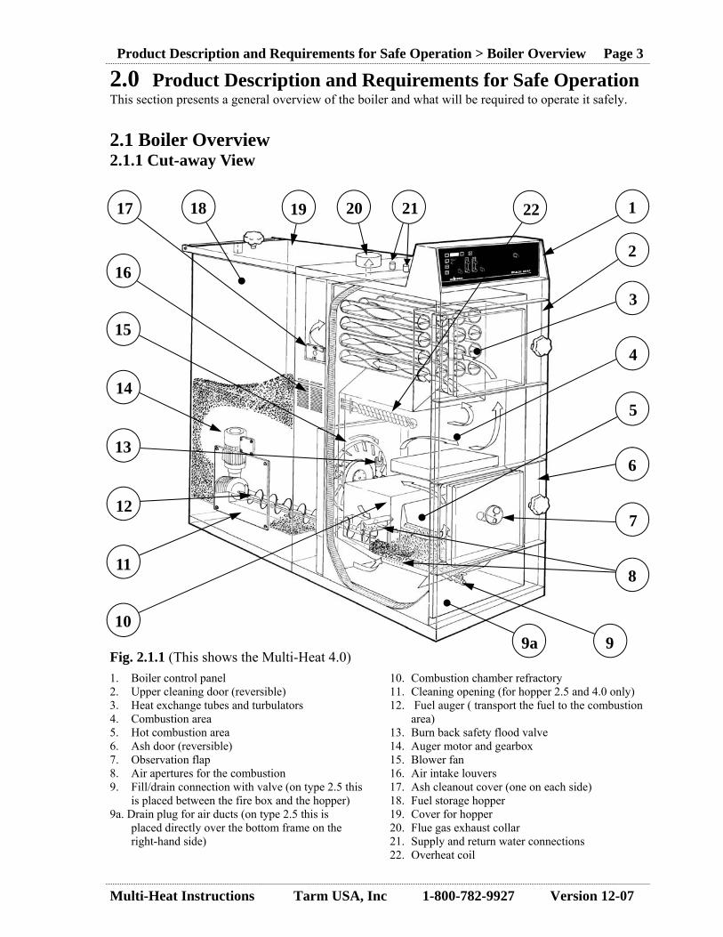
1. Boiler control panel 2. Upper cleaning door (reversible) 3. Heat exchange tubes and turbulators 4. Combustion area 5. Hot combustion area 6. Ash door (reversible) 7. Observation flap 8. Air apertures for the combustion 9. Fill/drain connection with valve (on type 2.5 this
is placed between the fire box and the hopper) 9a. Drain plug for air ducts (on type 2.5 this is
placed directly over the bottom frame on the right-hand side)
10. Combustion chamber refractory 11. Cleaning opening (for hopper 2.5 and 4.0 only) 12. Fuel auger ( transport the fuel to the combustion
area) 13. Burn back safety flood valve 14. Auger motor and gearbox 15. Blower fan 16. Air intake louvers 17. Ash cleanout cover (one on each side) 18. Fuel storage hopper 19. Cover for hopper 20. Flue gas exhaust collar 21. Supply and return water connections 22. Overheat coil
2
3
4
5
6
7
8
9 9a 10
11
12
13
14
15
16
17 18 19 20 21 22
2.0 Product Description and Requirements for Safe Operation This section presents a general overview of the boiler and what will be required to operate it safely. 2.1 Boiler Overview 2.1.1 Cut-away View
Fig. 2.1.1 (This shows the Multi-Heat 4.0)
Product Description and Requirements for Safe Operation > Boiler Overview Page 3
1

Multi-Heat Instructions Tarm USA, Inc 1-800-782-9927 Version 12-07
2.1.2 Boiler Fabrication and Testing The boiler is supplied fully assembled. Some provided components must be installed in the field near the boiler. After electrical, chimney, and plumbing connections are completed, the boiler can be filled, started, and operated. The boiler assembly consists of a boiler body with a fuel hopper (18) bolted to it. Jacket, doors, re-fractory's, turbulators, blower fan, and overheat coil are preinstalled. The cover door, micro switch, auger, fuel delivery system, auger motor, and gearbox are installed on the hopper. The control panel is mounted on the top front of the boiler. All sensors and electrical devices are pre-wired to the control panel. Multi-Heat boilers are designed and built in accordance with European Standard CEN 303-5. Safety and performance testing and listing North American market have been performed by OMNI Test Laboratories, Inc., Beaverton, Oregon. The boiler is tested and listed to applicable UL and other stan-dards. The boiler is not ASME stamped. The boiler should follow local or state installation require-ments. 2.1.3 Models and Applications Three Multi-Heat models are available (the model 1.5, 2.5, and 4.0), covering an output range up to 146,700 Btu/hr. Technical data for each Multi-Heat model is provided in Section 6.1. The boilers can be utilized as single heat sources, in parallel with other boilers, or in modular (multiple) boiler arrangements (where larger heating requirements exist). Residential and nonresiden-tial applications are appropriate. 2.2 Boiler Function 2.2.1 General Operation A generalized discussion of fuel stoking and combustion in the Multi-Heat boiler follows. Please refer to the Cut-away View of the Boiler in Section 2.1.1. The fuel auger (12) conveys fuel from the fuel storage hopper (18) to the boiler’s combustion area (4) in pulses of defined duration at preprogrammed intervals. The blower fan (15) supplies air at a programmed intensity, which is ducted directly to the area under the combustion chamber refractory arch (10) where combustion occurs. . Hot gases produced by combustion pass upward and through horizontal heat exchanger tubes equipped with removable turbulators, spiral or zig zag steel inserts which slow the movement of the gases improving heat exchange. Gases are exhausted through the flue collar (20) at the top of the boiler. The control panel (1) manages the rate of fuel delivery by the auger and the intensity of the combus-tion air from the blower fan. Boiler water temperature is monitored and the control panel regulates the combustion rate to keep the temperature near its set-point. Two combustion rates are set (by program-ming fuel delivery rates and air intensities) and provide a rapid and flexible means of meeting chang-ing heating demands. When the boiler achieves its set-point temperature, the combustion rate is auto-matically reduced to a lower output rate or a pilot (or standby) level to maintain the fire without in-creasing water temperature. Programming can be changed seasonally matching heating demand.
Product Description and Requirements for Safe Operation > Boiler Fabrication and Testing Page 4

Multi-Heat Instructions Tarm USA, Inc 1-800-782-9927 Version 12-07
2.2.2 Safety Systems The boiler has internal non-electrical safety systems to prevent damaging equipment in the case that any of three unlikely conditions occur.
• Pressure in the boiler exceeds 30 psi (over-pressure) • Boiler water temperature exceeds 100 degrees C (over-temperature) • Burning fuel inside the fuel feed tube through which the auger conveys fuel to the combustion
area (burn-back) To prevent an over-pressure condition, a pressure relief valve (provided) installed on the boiler sup-ply piping opens at 30 psi to relieve the boiler pressure. There are two systems which will activate in over-temperature situation. The first system includes a valve with a preset thermal element that opens when it measures boiler water temperature exceeding 100ºC, causing cool water to flow through the overheat cooling coil installed in the boiler water jacket, thereby reducing boiler water temperature. The second system is operated by a sensor measuring boiler water temperature (aquastat). When operating temperature exceeds 100ºC it stops blower fan and auger operation, interrupting heat production (high temperature reset). To prevent the boiler from going into stand-by for long periods of time, an aquastat (a Honeywell L6006C is provided) is installed to measure return water temperature. This aquastat will activate a heating zone to prevent the boiler from going into stand-by for long periods of time (see page 54). To extinguish a burn-back, a valve with a preset thermal element opens when the temperature at the fuel auger tube exceeds 100 degrees C, causing cool water to flood the auger tube, extinguishing any burning fuel in the tube. Additional to these safety systems, the control panel continuously monitors various sensors and elec-trical devices on the boiler. If readings vary from normal settings, the control panel produces audible alarms, displays error messages, and may shut the boiler down until the owner/ system operator deals with the condition. See Section 5.1 for a detailed discussion of these conditions. 2.2.3 Accessories The boiler is shipped with loose and installing parts. See Section 3.3.1 Receiving the Boiler for a complete listing of these parts. Cleaning tools are provided with the boiler. An auger extension is provided with models 2.5 and 4.0, for use when burning corn (see page 34). An ash hoe and ash pan are available to facilitate ash removal from the boiler. The model 2.5 is pro-vided with two interchangeable ash pans. A barometric damper (draft stabilizer) is available for regulating chimney draft. Plumbing around the boiler must include a three-port mixing valve in the orientation shown on instal-lation drawing. This valve must be a Termovar Model 4340A-3 or equal with a 60º C element. Tarm USA Inc provides this valve at extra cost. An Automatic Filling Device (AFD) may be purchased and is required for integrating a bulk fuel storage and conveyance system. The AFD mounts on top of the boiler fuel hopper and has an integral safety fire damper. When fuel inside the hopper is low, the damper automatically opens and the AFD control commands the auger in the fuel conveyance system to deliver fuel into the hopper. An Automatic Ash Removal Unit may be purchased (not available until mid-2008). The unit cycles periodically, conveying ash from the combustion area to an external ash container. Use of the Auto-matic Ash Removal Unit requires additional clearance on the sides of the boiler.
Product Description and Requirements for Safe Operation > Safety Systems Page 5
Multi-Heat Instructions Tarm USA, Inc 1-800-782-9927 Version 12-07
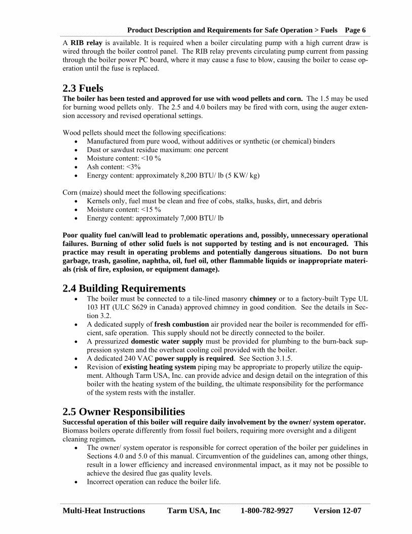
A RIB relay is available. It is required when a boiler circulating pump with a high current draw is wired through the boiler control panel. The RIB relay prevents circulating pump current from passing through the boiler power PC board, where it may cause a fuse to blow, causing the boiler to cease op-eration until the fuse is replaced. 2.3 Fuels The boiler has been tested and approved for use with wood pellets and corn. The 1.5 may be used for burning wood pellets only. The 2.5 and 4.0 boilers may be fired with corn, using the auger exten-sion accessory and revised operational settings. Wood pellets should meet the following specifications:
• Manufactured from pure wood, without additives or synthetic (or chemical) binders • Dust or sawdust residue maximum: one percent • Moisture content: <10 % • Ash content: <3% • Energy content: approximately 8,200 BTU/ lb (5 KW/ kg)
Corn (maize) should meet the following specifications:
• Kernels only, fuel must be clean and free of cobs, stalks, husks, dirt, and debris • Moisture content: <15 % • Energy content: approximately 7,000 BTU/ lb
Poor quality fuel can/will lead to problematic operations and, possibly, unnecessary operational failures. Burning of other solid fuels is not supported by testing and is not encouraged. This practice may result in operating problems and potentially dangerous situations. Do not burn garbage, trash, gasoline, naphtha, oil, fuel oil, other flammable liquids or inappropriate materi-als (risk of fire, explosion, or equipment damage). 2.4 Building Requirements
• The boiler must be connected to a tile-lined masonry chimney or to a factory-built Type UL 103 HT (ULC S629 in Canada) approved chimney in good condition. See the details in Sec-tion 3.2.
• A dedicated supply of fresh combustion air provided near the boiler is recommended for effi-cient, safe operation. This supply should not be directly connected to the boiler.
• A pressurized domestic water supply must be provided for plumbing to the burn-back sup-pression system and the overheat cooling coil provided with the boiler.
• A dedicated 240 VAC power supply is required. See Section 3.1.5. • Revision of existing heating system piping may be appropriate to properly utilize the equip-
ment. Although Tarm USA, Inc. can provide advice and design detail on the integration of this boiler with the heating system of the building, the ultimate responsibility for the performance of the system rests with the installer.
2.5 Owner Responsibilities Successful operation of this boiler will require daily involvement by the owner/ system operator. Biomass boilers operate differently from fossil fuel boilers, requiring more oversight and a diligent cleaning regimen.
• The owner/ system operator is responsible for correct operation of the boiler per guidelines in Sections 4.0 and 5.0 of this manual. Circumvention of the guidelines can, among other things, result in a lower efficiency and increased environmental impact, as it may not be possible to achieve the desired flue gas quality levels.
• Incorrect operation can reduce the boiler life.
Product Description and Requirements for Safe Operation > Fuels Page 6
Multi-Heat Instructions Tarm USA, Inc 1-800-782-9927 Version 12-07
• It is a precondition that the owner/ system operator has the will and correct attitude for firing with wood pellets or corn. Personal involvement and some work are necessary in order to “harvest the fruits” of this environmentally friendly and economically advantageous form of heating.
Throughout this manual, safety considerations are noted and discussed. A few general safety consid-erations to be considered are:
• Safety faults or deficiencies with the boiler or installation must be rectified as quickly as pos-sible, either by the owner/ system operator or the installer.
• Outlet pipes, ventilation channels, fresh air openings, etc. must not be closed or blocked. • The water supply for the boilers burn back safety flood device and overheat coil must never be
shut off. • Never use gasoline, gasoline-type lantern fuel, kerosene, charcoal lighter fluid, or similar liq-
uids to start or “freshen up” a fire in this boiler. • BOILER IS HOT WHILE IN OPERATION. KEEP CHILDREN, CLOTHING AND
FURNITURE AWAY. CONTACT MAY CAUSE SKIN BURNS. DO NOT TOUCH DURING OPERATION.
• Keep all flammable liquids and combustibles well away from the boiler while it is in use. Do not store fuel or other combustible material within the described installation clearances.
3.0 Boiler Installation & Start-up This section describes the steps to installing and starting-up the boiler. This section is directed at the installer.
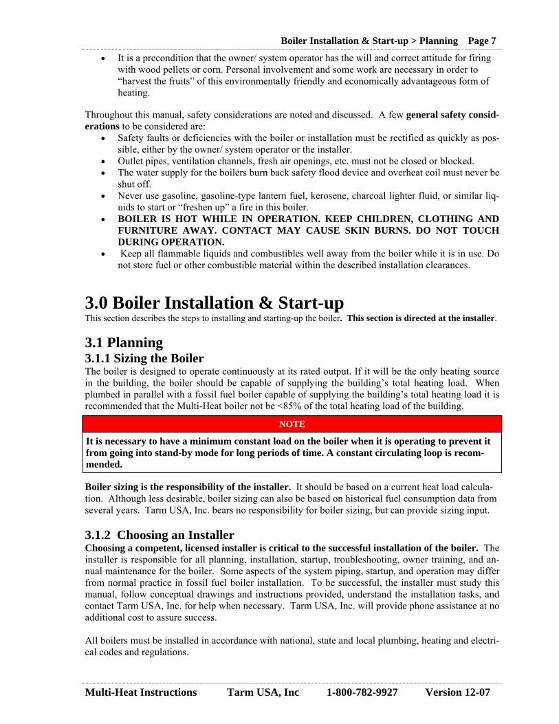
3.1 Planning 3.1.1 Sizing the Boiler The boiler is designed to operate continuously at its rated output. If it will be the only heating source in the building, the boiler should be capable of supplying the building’s total heating load. When plumbed in parallel with a fossil fuel boiler capable of supplying the building’s total heating load it is recommended that the Multi-Heat boiler not be <85% of the total heating load of the building.
Boiler sizing is the responsibility of the installer. It should be based on a current heat load calcula-tion. Although less desirable, boiler sizing can also be based on historical fuel consumption data from several years. Tarm USA, Inc. bears no responsibility for boiler sizing, but can provide sizing input. 3.1.2 Choosing an Installer Choosing a competent, licensed installer is critical to the successful installation of the boiler. The installer is responsible for all planning, installation, startup, troubleshooting, owner training, and an-nual maintenance for the boiler. Some aspects of the system piping, startup, and operation may differ from normal practice in fossil fuel boiler installation. To be successful, the installer must study this manual, follow conceptual drawings and instructions provided, understand the installation tasks, and contact Tarm USA, Inc. for help when necessary. Tarm USA, Inc. will provide phone assistance at no additional cost to assure success. All boilers must be installed in accordance with national, state and local plumbing, heating and electri-cal codes and regulations.
Boiler Installation & Start-up > Planning Page 7
NOTE
It is necessary to have a minimum constant load on the boiler when it is operating to prevent it from going into stand-by mode for long periods of time. A constant circulating loop is recom-mended.

Multi-Heat Instructions Tarm USA, Inc 1-800-782-9927 Version 12-07
3.1.3 Locating the Boiler (Clearances) DO NOT INSTALL THIS BOILER IN A MOBILE HOME. There is no safe way this boiler can be installed inside a mobile home. The boiler must be installed with the minimum installation clearances to combustible materials out-lined below. Clearances may only be reduced by means approved by the regulatory authorities (also see Positioning Data on page 46).
Boiler Installation & Start-up > Planning Page 8
A
B
C
Table 3.1 Clearances to Combustibles
Measurement Minimum Allowable Distance
A – Backwall to Appliance * 18” (457 mm)
B – Sidewall to Appliance ** 6” (152 mm)
C – Combustibles to Pipe 18” (457 mm)
Front of Appliance to Combustibles * 36” (914 mm)
Ceiling to Appliance 18” (457 mm)
* To allow for removal of the feed auger on the Multi-Heat 2.5 and Multi-Heat 4.0 boilers, it is necessary to have 40” (1,016 mm) of clearance either in front of, or to the rear of the boiler. **A clearance distance of 21” minimum is required on one side of the boiler to perform cleaning and maintenance tasks *** Sidewall clearances must be increased if use of the automatic ash removal unit is contemplated. Consult Tarm USA, Inc. for additional details.
• The boiler is not suitable for outdoor installation. It must be located in a weather-tight, pro-tected space.
• The boiler must be placed on a level and stable foundation. • If the floor on which the boiler sits contains combustible material, non-combustible floor pro-
tection must be provided a minimum 3/8” (10 mm) thick. It must cover the area under the ap-pliance and the installation clearance area outlined above. Floor protection must also cover the area under the chimney connector and extend at least 2” (50mm) on either side.
• Consider the logistics of delivering fuel to the boiler when choosing a boiler location. • It is important that enough space be available to ensure that the fuel auger can be removed for
service or replacement. For the 1.5 it is necessary to have a minimum clear space of 15”(381 mm) behind the boiler to allow removal of the fuel auger. (If there is insufficient space for this, the fuel auger on the 1.5 can be taken up through the hopper, by first leading the fuel au-ger 7” (178 mm) further back than the gear motor, and then leading the fuel auger up through the hopper.)

Multi-Heat Instructions Tarm USA, Inc 1-800-782-9927 Version 12-07
• On the 2.5 and 4.0, the fuel auger can be taken out at either end, and requires 40” (1,016 mm) of clearance either in front or at the rear of the boiler.
• If the boiler is placed in a room nearby inhabited rooms, so that flue gas can easily penetrate into these rooms, a carbon monoxide alarm must be installed that can give a warning regard-ing possible escapes of carbon monoxide into the inhabited rooms.
3.1.4 Plumbing & Mechanical The boiler must be connected to a suitable chimney. Chimney requirements are discussed in Section 3.2. A dedicated supply of fresh combustion air should be provided near the boiler for efficient and safe operation, but should not be directly connected to the boiler. A permanent or un-valved pressurized domestic cold water supply must be provided for the burn-back safety system and the overheat cooling coil. For the heating system piping, it is possible to use either copper or iron piping materials. The supply and return pipe should be insulated to avoid heat loss. Tarm USA, Inc. can provide conceptual piping diagrams showing the correct layout for a variety of situations. Use of a suitable antifreeze mix is allowed, but will cause a loss in heat transfer efficiency. If water quality is poor, water treatment additives should be considered. Boiler system water pH should be 8.0-8.6.
A thermostatic mixing valve, set to open at 60º C, is required to temper return water to prevent cold return water from reaching the boiler. This valve helps prevent boiler corrosion. Tarm USA, Inc. can provide this valve (part # K4340A3), at an additional cost. An aquastat (Honeywell L6006C (provided)) should be installed to sense periods of low heating sys-tem load by measuring return water temperature. This aquastat will activate a heating zone to prevent the boiler from going into stand-by for extended periods of time. An independent circulating pump (not provided), either always-on or powered through the boiler control panel with a relay, is required to circulate water continuously through the boiler during opera-tion.
Boiler Installation & Start-up > Planning Page 9
CAUTION
Any plastic or rubber tubing used with a Tarm boiler must have an oxygen barrier, or boiler corrosion will occur. If radiant tubing without an oxygen barrier is installed, water in the tubing part of the heating system must be separated from the boiler. Separation of system components is typically done by using a heat exchanger. Use of radiant tubing without an oxygen barrier will void the boiler warranty.
☼
CAUTION
Certain circulating pumps with higher current draw have caused fuse F1 on the Multi-Heat power PC board (see page 25) to blow. This problem can be avoided by wiring the circulator pump through a RIB type relay (Functional Devices product # RIBUIC or equal) (available at addi-tional cost from Tarm USA, Inc.). Connect the coil side (120V) to the boiler terminal block. Pro-vide the 120V supply through the normally-open (NO) relay contact to the circulator (see page 51 for wiring diagram).
☼
Multi-Heat Instructions Tarm USA, Inc 1-800-782-9927 Version 12-07
3.1.5 Electrical 240 VAC, 60 hertz, 4-wire power supply is required. If building power is lower (208 VAC, for ex-ample), a boosting transformer should be installed to correct the voltage. This electrical connection should be from a dedicated 15 amp, double-pole circuit breaker. An external alarm with its own electrical supply (24 V – 3 amp maximum) can be connected to termi-nal 11 and 12 on Terminal Block J5 on the Power PC Board inside the boiler control panel (see electri-cal diagram). These terminals provide a switching function only. They are connected to a “normally open” set of contacts and are not powered. These contacts close on any boiler alarm. This feature can be used to provide remote indication that an alarm has occurred. Locally enforced electrical codes must be followed. 3.2 Preparing the Chimney
• The boiler must be connected to a tile-lined chimney or to a Factory-Built Type UL 103 HT (ULC S629 in Canada) approved chimney. The chimney must be in good condition. No other appliance should be connected to this flue unless allowed by the local code authority. Consult your local inspector for chimney requirements and install the boiler in accordance with all ap-plicable codes.
• If corn burning is contemplated, use of higher grade stainless steel (a grade of 316 or higher is recommended).
• Follow manufacturer’s installation instructions for installing and supporting any specific chimney product.
• Flue gas exhaust temperatures can be low enough to cause condensation in chimneys. Con-densation will, over time, damage a masonry chimney. Accordingly, installation of a stainless steel chimney liner (such as 316 or AL-294C) inside the chimney flue is strongly recom-mended.
• The boiler has a built-in combustion blower fan. Therefore only small demands are made on the chimney draft. A 5” (127 mm) diameter flue is required for the 1.5. A 6” (152 mm) di-ameter flue is required for the 2.5 and 4.0.
• At the connection to a factory-built chimney, a dripless adaptor must be used. • The chimney draft must be stable and between 0.025” (0.6 mm) and 0.05” (1.25 mm) water
column. • The top of chimney must be 3’ above roof and 2’ above any portion of the roof within 10’
measured horizontally. Strong winds or a high chimney can cause excessive chimney draft, > 0.05” (1.25 mm) water column or an unstable draft. The solution to an unstable or high chimney draft is to install a barometric damper (draft regulator) to control the chimney draft at around 0.025” (0.6 mm) to 0.05” (1.25 mm) water column. A stable, properly regulated chimney draft also reduces the risk of burn-back in the fuel hopper of the boiler. Tarm USA, Inc. can provide a suitable barometric damper as an accessory to the boiler.
Boiler Installation & Start-up > Preparing the Chimney Page 10

Multi-Heat Instructions Tarm USA, Inc 1-800-782-9927 Version 12-07
Installation requirements for a barometric damper (draft regulator): • The diameter of the draft regulator must be equal or greater than that of the chimney connec-
tor. • The draft regulator should be installed as close as possible to the boiler, on the chimney con-
nection or on chimney itself. • The draft regulator adjustment should be made with a vacuum gauge, if possible, with the
boiler operating at full output. If the startup is made in warm weather, a readjustment may be necessary in cold weather.
• If, at the maximum adjustment (maximum opening of the shutter of the draft stabilizer), the draft is always higher than 0.05” (1.25 mm) of water column, a second draft regulator may be required.
Boiler Installation & Start-up > Preparing the Chimney Page 11
Barometric damper on vertical chimney
Barometric damper on horizontal chimney

Multi-Heat Instructions Tarm USA, Inc 1-800-782-9927 Version 12-07
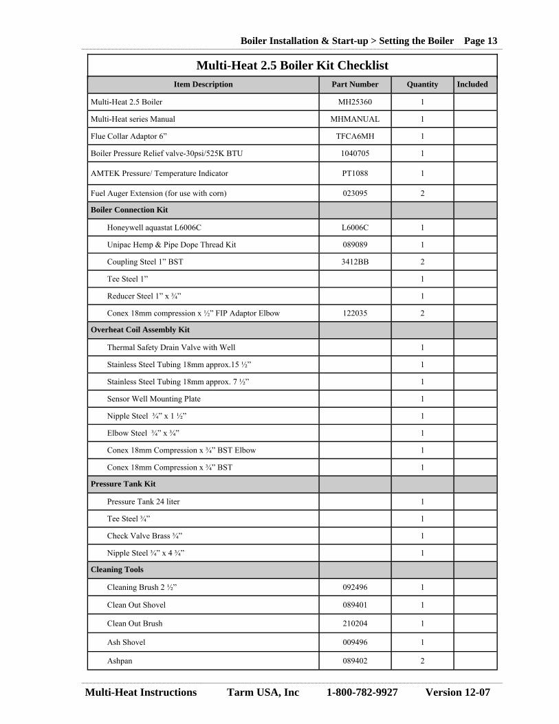
3.3 Setting the Boiler 3.3.1 Receiving the Boiler Boilers are shipped on a single skid. Loose materials are consolidated into boxes strapped to the skid or placed inside the combustion area or hopper of the boiler. Please unpack the boiler and boxes and verify that the items on the checklist have been supplied with the boiler (separate check lists for the 1.5, 2.5 and 4.0 boilers are provided below). Make certain that any damage or shortage is noted on the shipping receiver.
Boiler Installation & Start-up > Setting the Boiler Page 12
Item Description Part Number Quantity Included
Multi-Heat 1.5 Boiler MH15200 1
Multi-Heat series Manual MHMANUAL 1
Flue Collar Adaptor 5” TFCA5MH 1
Boiler Pressure Relief valve-30psi/525K BTU 1040705 1
AMTEK Pressure/ Temperature Indicator PT1088 1
Boiler Connection Kit
Unipac Hemp & Pipe Dope Thread Kit 089089 1
Coupling Steel 1” BST 3412BB 2
Tee Steel 1” 1
Reducer Steel 1” x ¾” 1
Conex 18mm compression x ½” FIP Adaptor Elbow 122035 2
“Y” Strainer Brass ½” x ½” BST 1
Overheat Coil Assembly Kit
Thermal Safety Drain Valve 1
Stainless Steel Tubing 18mm approx.14 ¼” 1
Stainless Steel Tubing 18mm approx. 5 ¾” 1
Sensor well ½” 1
Sensor Well Mounting Plate 1
Nipple Steel ¾” x 1 ½” 1
Elbow Steel ¾” x ¾” 1
Conex 18mm Compression x ¾” BST Elbow 1
Conex 18mm Compression x ¾” BST 1
Pressure Tank Kit
Pressure Tank 24 liter 1
Tee Steel ¾” 1
Check Valve Brass ¾” 1
Nipple Steel ¾” x 4 ¾” 1
Cleaning Tools
Cleaning Brush 210201 1
Ash Shovel 009496 1
Turbulator Spin Handle 091589 1
Honeywell aquastat L6006C L6006C 1
Multi-Heat 1.5 Boiler Kit Checklist
Multi-Heat Instructions Tarm USA, Inc 1-800-782-9927 Version 12-07
Boiler Installation & Start-up > Setting the Boiler Page 13
Item Description Part Number Quantity Included
Multi-Heat 2.5 Boiler MH25360 1
Multi-Heat series Manual MHMANUAL 1
Flue Collar Adaptor 6” TFCA6MH 1
Boiler Pressure Relief valve-30psi/525K BTU 1040705 1
AMTEK Pressure/ Temperature Indicator PT1088 1
Boiler Connection Kit
Unipac Hemp & Pipe Dope Thread Kit 089089 1
Coupling Steel 1” BST 3412BB 2
Tee Steel 1” 1
Reducer Steel 1” x ¾” 1
Conex 18mm compression x ½” FIP Adaptor Elbow 122035 2
Overheat Coil Assembly Kit
Thermal Safety Drain Valve with Well 1
Stainless Steel Tubing 18mm approx.15 ½” 1
Stainless Steel Tubing 18mm approx. 7 ½” 1
Sensor Well Mounting Plate 1
Nipple Steel ¾” x 1 ½” 1
Elbow Steel ¾” x ¾” 1
Conex 18mm Compression x ¾” BST Elbow 1
Conex 18mm Compression x ¾” BST 1
Pressure Tank Kit
Pressure Tank 24 liter 1
Tee Steel ¾” 1
Check Valve Brass ¾” 1
Nipple Steel ¾” x 4 ¾” 1
Cleaning Tools
Cleaning Brush 2 ½” 092496 1
Clean Out Shovel 089401 1
Clean Out Brush 210204 1
Fuel Auger Extension (for use with corn) 023095 2
Ashpan 089402 2
Ash Shovel 009496 1
Honeywell aquastat L6006C L6006C 1
Multi-Heat 2.5 Boiler Kit Checklist

Multi-Heat Instructions Tarm USA, Inc 1-800-782-9927 Version 12-07
Boiler Installation & Start-up > Setting the Boiler Page 14
Item Description Part Number Quantity Included
Multi-Heat 4.0 Boiler MH40360 1
Multi-Heat series Manual MHMANUAL 1
Flue Collar Adaptor 6” TFCA6MH 1
Boiler Pressure Relief valve-30psi/525K BTU 1040705 1
AMTEK Pressure/ Temperature Indicator PT1088 1
Fuel Auger Extension (for use with corn) 023095 1
Boiler Connection Kit
Unipac Hemp & Pipe Dope Thread Kit 089089 1
Coupling Steel 1” BST 3412BB 2
Tee Steel 1” 1
Reducer Steel 1” x ¾” 1
Conex 18mm compression x ½” FIP Adaptor Elbow 122035 2
Pressure Tank Kit
Pressure Tank 24 liter 1
Tee Steel ¾” 1
Check Valve Brass ¾” 1
Nipple Steel ¾” x 4 ¾” 1
Cleaning Tools
Clean Out Brush 210204 1
Ash Shovel 009496 1
Turbulator Spin Handle 091589 1
Honeywell aquastat L6006C L6006C 1
Multi-Heat 4.0 Boiler Kit Checklist
Please contact your dealer or Tarm USA, Inc. immediately if any of the above items are missing! Tarm USA, Inc. reserves the right to substitute equivalent equipment for any of the accessories listed above.

Multi-Heat Instructions Tarm USA, Inc 1-800-782-9927 Version 12-07
Fig. 3.1
3.3.2 Moving the Boiler See Section 6.1 Technical Data for weights and measurements of the boiler. The boiler is heavy and large. Moving it into place requires planning and resources. The boiler may be unloaded using a pallet jack or forklift Alternatively, it can be lifted from above by inserting a lift-ing bolt in holes provided in the flue gas exhaust collar (Fig. 3.1).
3.3.3 Boiler Set-up After the packaging is removed and the boiler is set into place, it should be checked to assure that all bolts and fittings are tight, gaskets are secure and undamaged, and cabling is undamaged and con-nected. Loose parts and accessories shipped with the boiler should be removed and stored in a safe place. A copy of this manual is shipped with the boiler for reference during installation. The boiler can be set using leveling bolts located on each corner (see fig. 3.2) (accessed in front by removing the lower cover on the 4.0 or opening the lower door on the 2.5) and in the center (accessed by removing
Boiler Installation & Start-up > Setting the Boiler Page 15
After positioning the boiler, remove and discard the wood wedges which hold the refractory blocks in place (Fig. 3.3). Make sure the refractory blocks are in their correct operating position. Push the turbulators fully into the heat exchange tubes. Remove all loose material and debris from the hopper and verify that the auger can turn freely.
Rear Front Side Fig. 3.2
Remove Both Sides
Arch Upper Flue Tile Fig. 3.3
Remove Remove
WARNING
Note that the center of gravity is NOT the center of the skid.

Multi-Heat Instructions Tarm USA, Inc 1-800-782-9927 Version 12-07
3.4 Connections to the Boiler Boiler Installation & Start-up > Connections to the Boiler Page 16
The following connections must be made to the boiler, in order for it to function: • The boiler flue gas exhaust collar must be connected to the chimney system, using the flue
adapter provided. • The heating system piping must be connected to the boiler supply and return connections. • Domestic cold water (pressurized) must be supplied to the burn back safety tank, from the
tank to the burn-back safety valve, and to the overheat coil in the boiler. • Electrical power must be provided at the boiler electrical terminal box.
3.4.1 Chimney Connection
The connection between the boiler and the chimney system should be single wall stainless steel, mini-mum 24 MSG, unless prohibited by the local code authority. If burning corn is contemplated, it is recommended that higher grade stainless steel be used (such as grade 316 or higher).
• The single wall chimney connector must not pass through an attic, roof space, closet or similar concealed space, or a floor, or ceiling.
• Where passage through a wall or partition of combustible construction is desired, the installa-tion must conform to NFPA 211 or to Canadian CAN/CSA B365.
• The chimney connection pipe must be placed over the outside of the boiler’s flue gas exhaust collar. A boiler flue with an internal dimension of 5.1” (130mm) or 5.9” (150 mm) respec-tively is used – see technical data in Section 6.1.
○ Multi-Heat 1.5 requires use of the 5-inch (127 mm) diameter Flue Collar Adapter, (provided with the boiler) (Part # TFCA5MH), to adapt the flue gas exhaust collar to 5-inch chimney pipe (See Fig. 3.4).
○ Multi-Heat 2.5 and 4.0 require use of the 6” (152 mm) diameter Flue Collar Adaptor, (provided with the boiler) (Part Number TFCA6MH), to adapt the flue gas exhaust collar to 6” chimney connector (See Fig. 3.4).
• The chimney connector sections must be attached to the boiler and to each other with the crimped (male) end pointing toward the boiler. All joints, including the connection at the boiler collar, must be secured with three sheet metal screws.
• A barometric regulator (draft damper) should be incorporated into the connector.
Flue Collar Adaptor
Smoke Temperature Sensor
Fig. 3.4
CAUTION
☼
☼
☼
☼
Do not install a flue damper in the exhaust venting system of this unit.
Do not connect this unit to a chimney flue serving another heating appliance, unless approved by the local code authority.
Do not connect the boiler to any air distribution duct or system.
Install vent at clearances specified by the vent manufacturer.

Multi-Heat Instructions Tarm USA, Inc 1-800-782-9927 Version 12-07
Boiler Installation & Start-up > Connections to the Boiler Page 17
3.4.2 Supply and Return Connections It is important to note that the boiler supply and return connections (size: 1”) at the top of the boiler are British Straight Thread (BST). BST threat pitch is the same as the NPT pitch used in North Amer-ica but does not incorporate a taper to the thread. To properly adapt between the BST on the boiler and NPT on the heating system piping, Two 1inch BST threaded couplings (part # 3412BB)(Fig. 3.5) and a Unipak Hemp & Pipe Dope Thread Kit (part no# 089089)(Fig. 3.6) have been provided with the boiler. Direction for use of the Unipak Hemp & Pipe Dope Thread Kit that is used to fill the taper between BST and NPT:
• Squeeze a “line” of Unipak jointing paste out on the external thread and spread it smoothly. The “hollows” of the thread must be filled with jointing paste;
• Pull out a suitable length of the packing yarn. • Wind the packing yarn smoothly and tight on the BST connection from the inner most part of
the pipe end in the thread direction. The thread should be filled with the packing yarn so that the tops of the threads are still visible. A thin layer of jointing paste is used in order to cover the packing yarn. Packing yarn must not cover the end of the pipe,
• Piping and fittings can be joined right away and the system can be used. The use of Unipak jointing paste and yarn allows adjusting of fittings and pipes. Residual jointing paste and yarn on the pipes can be removed by wiping with a rag or wire brush.
Unipak Hemp & Pipe Dope Thread Kit 1” BST Threaded Couplings
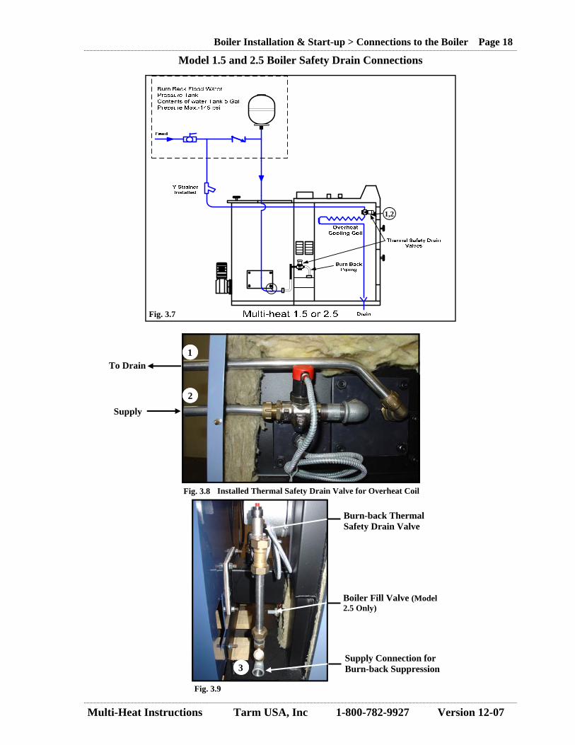
3.4.3 Boiler Safety Drain Valve Connections The Multi-Heat boiler has two SYR Valve safety devices that need to be connected to a cold water feed and drain. On the Multi-Heat 1.5 and 2.5 this is accomplished by two connections (Fig. 3.8 and 3.9). On the Multi-Heat 4.0 there is one connection (Fig. 3.11 and 3.12). These connections can be done on either the left or the right hand side of the boiler. On the 1.5 and 2.5 conex compression el-bows (part # 122035) are used to connect the water supply to the over-heat cooling coil on the front of the boiler. A Tank is supplied to guarantee a supply of water to the burn-back protection during a power outage. It needs to be installed as per diagram Fig. 3.7 or Fig. 3.10. A check valve also needs to be installed (Fig. 3.7 and 3.10). A Y-strainer should be installed on the Multi-Heat 1.5 and 2.5 coil connections to prevent sediment from damaging the SYR valve. This can be purchased from Tarm (Tarm part # FY32T2011). There is a y-strainer pre-installed on the Multi-Heat 4.0 (Fig. 3.7).
Fig. 3.5 Fig. 3.6
Multi-Heat Instructions Tarm USA, Inc 1-800-782-9927 Version 12-07
Boiler Installation & Start-up > Connections to the Boiler Page 18 Model 1.5 and 2.5 Boiler Safety Drain Connections
Installed Thermal Safety Drain Valve for Overheat Coil
Supply
To Drain
Supply Connection for Burn-back Suppression
Fig. 3.8
Fig. 3.9
Fig. 3.7
1
2
3
1,2
3
Burn-back Thermal Safety Drain Valve
Boiler Fill Valve (Model 2.5 Only)

Multi-Heat Instructions Tarm USA, Inc 1-800-782-9927 Version 12-07
Model 4.0 Boiler Safety Drain Connections
Boiler Installation & Start-up > Connections to the Boiler Page 19
Fig. 3.10
Fig. 3.11
Supply Connection for Burn-back Suppression and Overheat Cooling Coil
Burn-back Thermal Safety DrainValve
Overheat Cooling Coil Thermal Safety Drain Valve
1
2
Fig. 3.12
Overheat Cooling Coil Drain Connection
2
1

Multi-Heat Instructions Tarm USA, Inc 1-800-782-9927 Version 12-07
Boiler Installation & Start-up > Connections to the Boiler Page 20
Fig. 3.13
Fitting the overheat cooling coil

Multi-Heat Instructions Tarm USA, Inc 1-800-782-9927 Version 12-07
Termovar Mixing Valve Balancing Valve Must be used above port 1. The boiler’s C-3 circulator needs to be wired through a switch or RIB relay. Domestic cold water is connected as shown for Model 1.5 and 2.5. Model 4.0 has only one connec-tion to the SYR-Valve burn back piping.
Boiler Installation & Start-up > Heating System Plumbing and Testing Page 21
3.4.4 Electrical Connections Electrical connections to the boiler are made on Block X8 in the electrical junction box located on the rear of the boiler control panel (Fig. 3.14). See the connection diagram in Section 6.3. L1 and L2 are the two “hot” power legs, N is neutral and Point 4 is for the ground wire. The boiler circulator pump C-1 (120 volt) can be connected on Block X9 in the junction box through a RIB type relay (Fig.6.6). Connecting the circulator directly to the boiler could cause high current draw on the boiler’s power board. Fig. 3.15 shows a RIB relay mounted to the boiler’s electrical junction box.
Block X8 Block X9
Electrical Junction Box Mounted RIB Relay Fig. 3.14 Fig. 3.15
3.5 Heating System Plumbing and Testing
Fig. 3.16
Notes:
* Complete plumbing diagrams are located on page 54 and 55.

Multi-Heat Instructions Tarm USA, Inc 1-800-782-9927 Version 12-07
Boiler Installation & Start-up > Filling and Venting Page 22
The temperature/ pressure indicator (provided, part # PT1088), boiler pressure relief valve (provided, part # 1040705), thermostatic mixing valve (accessory, part # K4340A3) TV-1, and boiler circulator C-1 (not provided) should be incorporated in the heating system piping exactly as shown (Fig. 3.16). The ball valve (not provided) upstream of Port 1 of valve TV-1 should be set at half open (and the handle removed), in order for the tempering loop to function correctly. If accessory K4340A3 Termo-var mixing valve is provided for use as TV-1, the unions supplied with the valve have internal ball valves which must be fully open. The Burn-back Flood Water Safety Tank (provided, part # 142100) should be mounted as per Fig. 3.7 and Fig. 3.10. The domestic cold water supply piping for the Overheat Cooling Coil and burn-back system must be connected exactly as shown. The supply tap teed off upstream of the line check valve is connected to the thermal valve upstream of the overheat cooling coil. The downstream tap is con-nected to the thermal valve upstream of the burn-back connection to the auger tube. See the diagram on page 20 (Fig. 3.13).
3.6 Filling and Venting If water quality is poor or pH unsatisfactory, the installer should consider water treatment addi-tives during filling and water testing as part of annual maintenance. The connection for filling the boiler with water (Fig. 3.17 and 3.18) is, for the 1.5 and 4.0, situated behind the bottom front jacket panel. For the 2.5, the fill/ drain connection is situated between the fuel hopper and the boiler body. During filling the circulation pump is switched off. Filling takes place through a hose which is screwed onto the fill faucet and connected to a water supply faucet. Fill the hose with water prior to filling the boiler, otherwise air in the hose will be pushed into the boiler sys-tem. Remove the hose after filling up. High quality air elimination equipment is recommended in the heating system installation.
Fig. 3.17 Fig. 3.18 Fill Valve Model 2.5 Fill Valve Models 1.5 & 4.0
CAUTION
It is important to back flush the burn back plumbing after installation to remove any debris that may be in the system that could prevent operation of the safety flood valve. This includes check-ing the Y-strainer.
☼
NOTE
The heating system main supply and return piping will need to be at least 1.25” (32 mm) for correct boiler heat output distribution. All field-run piping should be back-flushed to clean and remove debris. Adequate filling and venting ports should be added so that air can be removed from the system. The system should be pressure tested before being placed into service.

Multi-Heat Instructions Tarm USA, Inc 1-800-782-9927 Version 12-07
Boiler Installation & Start-up > Boiler Programming Page 23
3.7 Boiler Programming
E F G
H
A
B
C
R
P
K
L
M
ºC
Boi
ler
On
Whe
n L
it
Ala
rm O
n D
ispl
ay
If L
it Pu
sh T
o C
lear
Man
ually
A
dvan
ces
Fuel
Into
80
MEN
U
ALA
RM
ON
SEK
. SE
K.
MIN
.
REG
SET J
Man
ually
Pu
lls
Fuel
Out
Dis
play
ing
Tem
pera
ture
of
Wat
er L
eavi
ng B
oile
r
Dis
play
ing
Tem
pera
ture
of
Wat
er R
etur
ning
To
Boi
ler
Dis
play
ing
Boi
ler
Wat
er
Dis
play
ing
Flue
Gas
Not
Use
d
Not
Use
d
Cir
cula
tor
Pum
p O
n W
hen
Lit
Use
d w
ith “
R”
To
Adj
ust
Boi
ler
Se
t Poi
nt
Ope
ratin
g A
t Hig
h W
hen
Lit
Ope
ratin
g A
t Lo
Whe
n L
it
Ope
ratin
g O
n St
and
By
Whe
n L
it
Man
ual
Whe
n L
it
A
uto
(2 S
tep)
I
100%
30
-100
%
UP Dow
n
Adj
ust
Mod
e
Push
To
Cyc
le
Thr
u T
emps
M
onito
red
At
Lef
t D
Fig
3.19
A.
Dis
play
……
……
……
……
……
……
……
30
B.
MEN
U b
utto
n……
……
……
……
……
….2
9 C
. M
ode
of O
pera
tion…
……
……
……
……
..30
D.
Ove
rhea
t aqu
asta
t/circ
uit b
reak
er…
……
…32
E.
O
N/O
FF b
utto
n-ig
nite
/ext
ingu
ish…
……
…29
Page
F.
Ala
rm re
set-c
ance
l ala
rm…
……
……
……
…32
G
. M
anua
l wor
m c
onve
yer/a
uger
-for
war
ds…
….2
9 H
. M
anua
l wor
m c
onve
yer/a
uger
-bac
kwar
ds…
.29
I. Li
ght d
iode
s J.
SET=
boile
r tem
pera
ture
……
……
……
……
.29
Page
K.
Hig
h ou
tput
……
……
……
……
……
……
…31
L.
Lo
w o
utpu
t……
……
……
……
……
……
….3
1 M
. Fi
ring
on st
andb
y (p
ilot b
urn)
……
……
……
31
N.
Circ
ulat
or p
ump
switc
h……
……
……
……
..32
O.
REG
(reg
ulat
ion
adju
stm
ent)…
……
……
….2
9
Page
Multi-Heat Instructions Tarm USA, Inc 1-800-782-9927 Version 12-07
Boiler Installation & Start-up > Boiler Programming Page 24
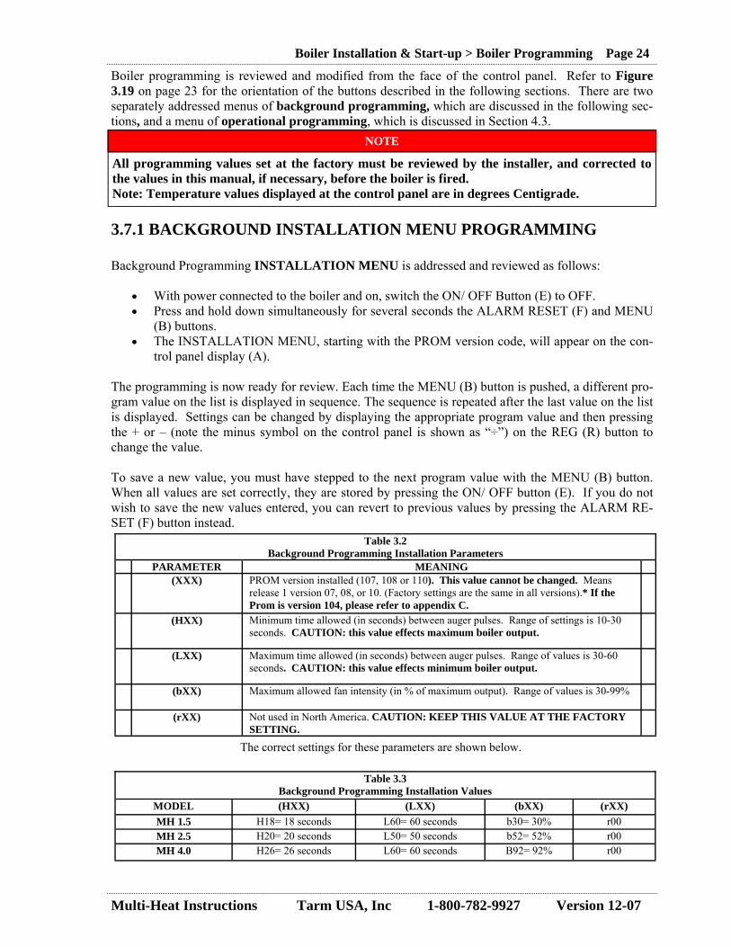
Boiler programming is reviewed and modified from the face of the control panel. Refer to Figure 3.19 on page 23 for the orientation of the buttons described in the following sections. There are two separately addressed menus of background programming, which are discussed in the following sec-tions, and a menu of operational programming, which is discussed in Section 4.3.
3.7.1 BACKGROUND INSTALLATION MENU PROGRAMMING Background Programming INSTALLATION MENU is addressed and reviewed as follows:
• With power connected to the boiler and on, switch the ON/ OFF Button (E) to OFF. • Press and hold down simultaneously for several seconds the ALARM RESET (F) and MENU
(B) buttons. • The INSTALLATION MENU, starting with the PROM version code, will appear on the con-
trol panel display (A). The programming is now ready for review. Each time the MENU (B) button is pushed, a different pro-gram value on the list is displayed in sequence. The sequence is repeated after the last value on the list is displayed. Settings can be changed by displaying the appropriate program value and then pressing the + or – (note the minus symbol on the control panel is shown as “÷”) on the REG (R) button to change the value. To save a new value, you must have stepped to the next program value with the MENU (B) button. When all values are set correctly, they are stored by pressing the ON/ OFF button (E). If you do not wish to save the new values entered, you can revert to previous values by pressing the ALARM RE-SET (F) button instead.
The correct settings for these parameters are shown below.
Table 3.2 Background Programming Installation Parameters
PARAMETER MEANING (XXX) PROM version installed (107, 108 or 110). This value cannot be changed. Means
release 1 version 07, 08, or 10. (Factory settings are the same in all versions).* If the Prom is version 104, please refer to appendix C.
(HXX) Minimum time allowed (in seconds) between auger pulses. Range of settings is 10-30 seconds. CAUTION: this value effects maximum boiler output.
(LXX) Maximum time allowed (in seconds) between auger pulses. Range of values is 30-60 seconds. CAUTION: this value effects minimum boiler output.
(bXX) Maximum allowed fan intensity (in % of maximum output). Range of values is 30-99%
(rXX) Not used in North America. CAUTION: KEEP THIS VALUE AT THE FACTORY SETTING.
Table 3.3 Background Programming Installation Values
MODEL (HXX) (LXX) (bXX) (rXX) MH 1.5 H18= 18 seconds L60= 60 seconds b30= 30% r00 MH 2.5 H20= 20 seconds L50= 50 seconds b52= 52% r00 MH 4.0 H26= 26 seconds L60= 60 seconds B92= 92% r00
NOTE
All programming values set at the factory must be reviewed by the installer, and corrected to the values in this manual, if necessary, before the boiler is fired. Note: Temperature values displayed at the control panel are in degrees Centigrade.

Multi-Heat Instructions Tarm USA, Inc 1-800-782-9927 Version 12-07
Boiler Installation & Start-up > Boiler Programming Page 25
3.7.2 Background OPERATION MENU Programming Background Programming OPERATION MENU is addressed and reviewed as follows:
• With power connected to the boiler and on, switch the ON/ OFF Button (E) to OFF. • Press and hold down simultaneously for several seconds the ALARM RESET (F) and OP-
ERATION MODE (C) buttons. • The OPERATIONS MENU, starting with three horizontal lines, will appear on the control
panel display (A). The programming is now ready for review. Each time the OPERATION MODE (C) button is pushed, a different program value on the list is displayed in sequence. The sequence is repeated after the last value on the list is displayed. Settings can be changed by displaying the appropriate program value and then pressing the + or – (note the minus symbol on the control panel is shown as “÷”) on the REG (R) button to change the value. When programming is completed, the new values are saved by pressing the ON/ OFF (E) button. To save a new value, you must have stepped to the next program value with the OPERATION MODE (C) button. If you do not wish to save the new values entered, you can revert to previous values by press-ing the ALARM RESET (F) button.
Correct settings for (HX.X) and (LX.X) are shown below.
Table 3.4 Background Programming Operational Parameters
PARAMETER MEANING (-XX) Minimum intensity for the blower (in percent of maximum output). The correct set-
ting is (-20)=20%. Possible settings are 10-20-30-40-50.
(HX.X) Auger running time (duration of an auger pulse in seconds) in high output mode. The correct settings for each model are given in the table below. Possible settings are 0.1 - 6.0 seconds.
(LX.X) Auger running time (duration of an auger pulse in seconds) in low output mode. The correct settings for each model are given in the table below. Possible settings are 0.1 - 6.0 seconds.
(PXX) Blower running time in seconds (with maximum air quantity) in standby (or pilot burn) mode. The correct setting is (P05) = 5 seconds. Possible settings are 0-10 seconds. (Do not go above the 5 second setting, a higher setting will remove the coals)
(X.XH) Not used in North America. Should not appear during review. (X.XL) Not used in North America. Should not appear during review. (CaL) Not used in North America. Should not appear during review. (au-) Not used in North America. Should not appear during review. If any of these four
preceding value appears on the display, the boiler is in an operating mode not supported in North America. To change the boiler to the correct mode, go to the (au-) parameter, change it to (no-), and save and confirm. CAUTION: YOUR BOILER SHOULD ONLY OPERATE IN THE (no-) MODE.
(no-) Boiler is in correct operating mode for North America. CAUTION: DO NOT CHANGE THIS PARAMETER.
Table 3.5 Background Programming Installation Values
MODEL (HX.X) (LX.X)
MH 1.5 H1.0= 1.0 second L1.0= 1.0 second
MH 2.5 H0.3= 0.3 seconds L0.2= 0.2 seconds
MH 4.0 H0.6= 0.6 seconds L0.3= 0.3 seconds
Multi-Heat Instructions Tarm USA, Inc 1-800-782-9927 Version 12-07
Boiler Installation & Start-up > Final Installation Checklist Page 26
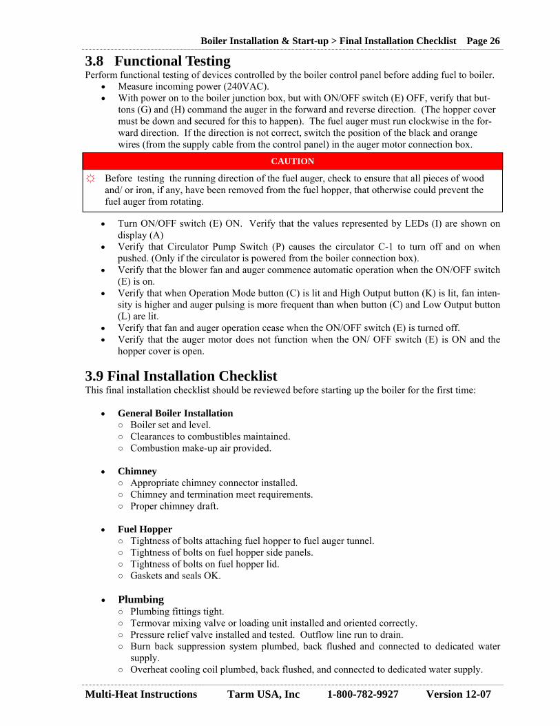
3.8 Functional Testing Perform functional testing of devices controlled by the boiler control panel before adding fuel to boiler.
• Measure incoming power (240VAC). • With power on to the boiler junction box, but with ON/OFF switch (E) OFF, verify that but-
tons (G) and (H) command the auger in the forward and reverse direction. (The hopper cover must be down and secured for this to happen). The fuel auger must run clockwise in the for-ward direction. If the direction is not correct, switch the position of the black and orange wires (from the supply cable from the control panel) in the auger motor connection box.
• Turn ON/OFF switch (E) ON. Verify that the values represented by LEDs (I) are shown on display (A)
• Verify that Circulator Pump Switch (P) causes the circulator C-1 to turn off and on when pushed. (Only if the circulator is powered from the boiler connection box).
• Verify that the blower fan and auger commence automatic operation when the ON/OFF switch (E) is on.
• Verify that when Operation Mode button (C) is lit and High Output button (K) is lit, fan inten-sity is higher and auger pulsing is more frequent than when button (C) and Low Output button (L) are lit.
• Verify that fan and auger operation cease when the ON/OFF switch (E) is turned off. • Verify that the auger motor does not function when the ON/ OFF switch (E) is ON and the
hopper cover is open.
3.9 Final Installation Checklist This final installation checklist should be reviewed before starting up the boiler for the first time:
• General Boiler Installation ○ Boiler set and level. ○ Clearances to combustibles maintained. ○ Combustion make-up air provided.
• Chimney ○ Appropriate chimney connector installed. ○ Chimney and termination meet requirements. ○ Proper chimney draft.
• Fuel Hopper
○ Tightness of bolts attaching fuel hopper to fuel auger tunnel. ○ Tightness of bolts on fuel hopper side panels. ○ Tightness of bolts on fuel hopper lid. ○ Gaskets and seals OK.
• Plumbing
○ Plumbing fittings tight. ○ Termovar mixing valve or loading unit installed and oriented correctly. ○ Pressure relief valve installed and tested. Outflow line run to drain. ○ Burn back suppression system plumbed, back flushed and connected to dedicated water
supply. ○ Overheat cooling coil plumbed, back flushed, and connected to dedicated water supply.
CAUTION
Before testing the running direction of the fuel auger, check to ensure that all pieces of wood and/ or iron, if any, have been removed from the fuel hopper, that otherwise could prevent the fuel auger from rotating.
☼

Multi-Heat Instructions Tarm USA, Inc 1-800-782-9927 Version 12-07
Boiler Installation & Start-up > Combustion and Performance Testing Page 27
• Electrical ○ Boiler connected to dedicated 240 volt, 60 hertz, 4-wire power supply. ○ Fuel auger rotating in correct direction. ○ Functional testing performed satisfactorily.
3.10 Combustion and Performance Testing The boiler should be loaded with fuel and fired to test for performance, using Section 4.6 as a guide-line.
• Provision should be made for dissipating the heat generated. • Start by programming the boiler Operational Programming per Table 4.3.1 or 4.3.2. • Load enough fuel to complete entire testing program. • Verify all operating modes. • Verify control strategy. • Measure combustion gases and efficiency, as required.
If fine adjustment of the Operational Programming is required or desired, follow these guidelines: The boiler should to be adjusted first at HIGH output (K), which only should be slightly higher than the maximum heating requirement of the house (see Section 4.2 for function of programming buttons). This “high output” may be adjusted seasonally, as heat demands change, to best match output to de-mand. After this, set at “LOW output”. When adjusting the boiler it is recommend that the flue gas temperature be at a minimum of 120°C (248°F) when burning wood pellets, and at least 140°C (284°F) when burning corn. Further fine tun-ing adjustments of the quantities of air and fuel are carried out in accordance with the following guide-lines in Table 3.6 by the installer with a combustion gas analyzer.
The flame should to be yellow and slightly bluish in color and very turbulent (Fig 3.20). If the flame is short and blue, either the interval time between fuel auger feeds (pulses) or the air combustion quantity must be reduced incrementally. Flame should completely fill the arch. If the flame is long and reddish-yellow, either the interval time be-tween fuel auger feeds (pulses) or the air combustion quantity must be increased incrementally. Color of the flue gas: If the flue gas is black or dark, this is because the fuel is getting insuf-ficient air. The flue gas must be white or light-colored or transparent
Remember: Always ensure that you have a pen and paper ready every time you adjust the settings on the control. (Tables can be seen in Section 4.3) When an adjustment is made on a setting, the information regarding this will be shown in the display for approx. 10 seconds after the last adjustment or until another function is carried out.
Table 3.6 Recommended CO2 Flue Gas Targets
Flue Gas CO2 Content (HIGH output)
Flue Gas CO2 Content (LOW output)
Fuel type % %
Wood Pellets 13-14 9-12
Corn 13-14 9-12
Fig. 3.20 Fire at High Output
Multi-Heat Instructions Tarm USA, Inc 1-800-782-9927 Version 12-07
Boiler Operation and Maintenance > Boiler Control Strategy Page 28
4.0 BOILER OPERATION AND MAINTENANCE
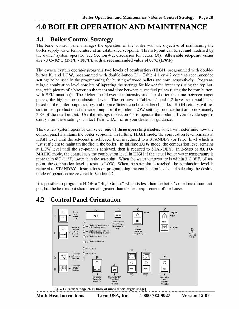
4.1 Boiler Control Strategy The boiler control panel manages the operation of the boiler with the objective of maintaining the boiler supply water temperature at an established set-point. This set-point can be set and modified by the owner/ system operator (see Section 4.2, discussion for button (J)). Allowable set-point values are 78ºC- 82ºC (172ºF - 180ºF), with a recommended value of 80ºC (176ºF). The owner/ system operator programs two levels of combustion (HIGH, programmed with double-button K, and LOW, programmed with double-button L). Table 4.1 or 4.2 contains recommended settings to be used in the programming for burning of wood pellets and corn, respectively. Program-ming a combustion level consists of inputting the settings for blower fan intensity (using the top but-ton, with picture of a blower on the face) and time between auger fuel pulses (using the bottom button, with SEK notation). The higher the blower fan intensity and the shorter the time between auger pulses, the higher the combustion level. The settings in Tables 4.1 and 4.2 have been established based on the boiler output ratings and upon efficient combustion benchmarks. HIGH settings will re-sult in heat production at the rated output of the boiler. LOW settings produce heat at approximately 30% of the rated output. Use the settings in section 4.3 to operate the boiler. If you deviate signifi-cantly from these settings, contact Tarm USA, Inc. or your dealer for guidance. The owner/ system operator can select one of three operating modes, which will determine how the control panel maintains the boiler set-point. In fulltime HIGH mode, the combustion level remains at HIGH level until the set-point is achieved, then is reduced to a STANDBY (or Pilot) level which is just sufficient to maintain the fire in the boiler. In fulltime LOW mode, the combustion level remains at LOW level until the set-point is achieved, then is reduced to STANDBY. In 2-Step or AUTO-MATIC mode, the control sets the combustion level in HIGH if the actual boiler water temperature is more than 6ºC (11ºF) lower than the set-point. When the water temperature is within 3ºC (6ºF) of set-point, the combustion level is reset to LOW. When the set-point is reached, the combustion level is reduced to STANDBY. Instructions on programming the combustion levels and selecting the desired mode of operation are covered in Section 4.2. It is possible to program a HIGH a “High Output” which is less than the boiler’s rated maximum out-put, but the heat output should remain greater than the heat requirement of the house. 4.2 Control Panel Orientation
Fig. 4.1 (Refer to page 26 or back of manual for larger image)

Multi-Heat Instructions Tarm USA, Inc 1-800-782-9927 Version 12-07
Boiler Operation and Maintenance > Control Panel Orientation Page 29
(E) Start/Stop (J) Boiler Set Temperature (R) Regulation (B) Menu (G) Manual Fuel Auger – Forward (H) Manual Fuel Auger – Backward
The ON/OFF button (E) is used to start or stop the boiler. If the boiler is ON, the LED above the button will be lit. The boiler operational temperature, or set-point, is adjusted by keeping SET (J) pressed in and simultaneously pressing on + or – on REG (R). The temperature can be adjusted in a range from 60 to 85°C. The set-point should be kept between 78 - 82ºC (172 - 180ºF) for proper boiler operation. The recommended value is 80°C (176ºF). (When “SET” is pressed, the LED will light up - “SET” and the adjusted temperature will be shown on the display). Adjustable parameters can be changed up or down in value by pressing the + or – (note the minus symbol on the control panel is shown as “÷”) on the REG (R). Each time this button is pushed, the display changes to show the current value of the next of the four operational temperatures be-ing monitored. The LED to the left of the displayed parameter will be lit when its value is displayed. (See description below for a listing of monitored parameters). This button is also used for back-ground programming, see Section 3.7.1. Use this button (G) (with the symbol for the fuel auger with the arrow pointing to the right) to manually advance the fuel auger forward. As long as the button is pressed, the fuel auger will run forward, pushing fuel into the combustion chamber. However, this button will not operate when the hinged cover on the fuel hopper is open. Use this button (H) (with the symbol for the fuel auger with the arrow pointing to the left) to manually turn the fuel auger back-ward. For safety, the fuel auger will only run backwards for 3 sec-onds even if the button is depressed longer. This button will not operate when the hinged cover on the fuel hopper door is open.
Letters in brackets () in this section refer to the button with the corresponding letter on the control panel. All temperature values displayed on the control panel are in degrees Centigrade.

Multi-Heat Instructions Tarm USA, Inc 1-800-782-9927 Version 12-07
Boiler Operation and Maintenance > Control Panel Orientation Page 30
(A) & (I) Operational Tem-perature Display
(C) Operation Mode
During operation of the boiler it is possible with the MENU button (B) to select one of four monitored operational temperatures to be shown on the display (A). Each time the MENU button is pressed the display will scroll to the next temperature and light the diode corresponding to the display temperature on (I). The Operational Temperatures that can be displayed are:
• Supply temperature = boiler supply (outgoing) water tem-perature.
• Return temperature = boiler return water temperature • Set temperature = the set-point, or target boiler supply wa-
ter temperature. • Smoke temperature = the temperature of the boiler’s ex-
haust gases. During normal operation it is a good idea to have the smoke ex-haust temperature displayed, making it possible to see whether the boiler requires cleaning. The exhaust temperature must not be too low since this can cause condensation in the chimney. How low the temperature should be allowed depends on the chimney, but exhaust gas temperatures below 120°C (248ºF), when combustion has been at HIGH or LOW, are not normally recommended.
Note: If you press one of the buttons (J - M), the selected value will be shown for 5 seconds - after which the value you have chosen will be shown once again.
With this button, it is possible to switch between 2-Step or AUTO-MATIC mode (LED above button (C) is OFF) or constant HIGH or LOW output mode (LED above button (C) is lit). Three possible OPERATION MODES that can be selected by pressing button (C):
1. 2-Step Operation (AUTOMATIC) = no light above but-ton (C).
2. Fixed High Output (HIGH) = LEDs on simultaneously above button (C) and on the 100% (K) double button.
3. Fixed Low Output (LOW)= LEDs on simultaneously above button (C) and on the 30-100% (L) double button.
The greatest efficiency can be achieved by running the boiler in the 2-Step (AUTOMATIC) operation mode. During 2-step operation, the lowest smoke temperature and the highest efficiency are achieved. The boiler will run at a high output until the supply water temperature is 3°C (6°F) below the set-point temperature, and then switch down to the programmed low output. The opera-tion will continue on a Low Output until the set-point water tem-perature is achieved. If the supply water temperature cannot be maintained with the Low Output, the boiler will switch back to the High Output when the supply water temperature has dropped to 6°C (11°F) below the boiler set-point value.
80

Multi-Heat Instructions Tarm USA, Inc 1-800-782-9927 Version 12-07
Boiler Operation and Maintenance > Control Panel Orientation Page 31
(K) High Output (HIGH) mode (L) Low Output (LOW) mode (M) STANDBY (Pilot) mode
High output for the boiler is set using the double-button above the 100% symbol (K). The lowest button is used to set the number of seconds between each fuel delivery. This can be set between 5 and 30 seconds. To display this setting in the display (A), press in and hold the SEK button and adjust up or down by pressing on “+” or “÷” on REG (R). In the same manner, the upper button is used to set the combustion air intensity from 0 - 100%, where 100% corresponds to maximum air quantity. The blower setting is shown in the display (A) when holding in the upper (K) button.
Note: The fuel quantity and the combustion air intensity are related and must be adjusted together to achieve the best performance.
See Section 4.3 for recommended initial settings.
Low Output is set using the double- button above the 30-100% symbol (L). The lowest button is used to set the number of sec-onds between each fuel delivery - this can be set between 10 and 60 seconds (but should never be less than the setting for High Out-put). To display the setting in the display (A), press in and hold “SEK” and adjust up or down by means of pressing “+” or “÷” on REG (R). Using the uppermost button, set the blower’s air quan-tity from 0 to 100, where 100 corresponds to maximum air quan-tity. The blower setting is shown in the display (A) when holding in the top part of the (L) button.
Note: The fuel quantity and the combustion air intensity are related and must be adjusted together to achieve the best performance.
Note: Nominal output in this mode should not be less than 30% of full output. See also technical data.
See Section 4.3 for recommended initial settings.
Control of the STANDBY or Pilot Mode is set with the MIN but-ton (M). The setting shown on the display (A) when pushing but-ton (M) is the number of minutes between each fuel delivery. This mode is only active when the boiler‘s supply water temperature is above the SET temperature. STANDBY can be set between 1 and 60 minutes. STANDBY maintains a small standby "pilot" ember bed in the combustion chamber, hot enough to keep the fire lit but not raising boiler supply water temperature. It must be adjusted by trial and error. See Section 4.3 for recommended initial settings.

Multi-Heat Instructions Tarm USA, Inc 1-800-782-9927 Version 12-07
Boiler Operation and Maintenance > Operating Modes Settings Page 32
(D) Overheat aquastat (P) Circulator Pump (F) Alarm Reset
If the boiler supply water temperature reaches 100°C (212 °F) the overheat aquastat/circuit breaker will switch the boiler OFF, and the display will show alarm “A-2” (See Alarm Summary in Sec-tion 5.1). The aquastat/circuit breaker must be reset manually, after the boiler has cooled down sufficiently (to approximately 70 to 80 °C (158 to 176 °F)). This is accomplished by unscrewing the black protective cap (D) and pressing the pin in the center of the aquastat, until a “click” is heard (be sure to replace the cover). The Alarm Reset button (F) must be pressed to clear the alarm. The circulation pump C-1 for the boiler can be switched ON (LED is lit) or OFF by pressing this button (P). Circulation pump C-1 should be ON whenever the boiler is in operation All alarms are reset or cleared with this button. The alarms listed in Section 5.1 will appear on the display (A). If there are no alarms present, the button is used in conjunction with other buttons to enter the background programming menus (see Section 3.7). Please Refer to Section 5.0, Troubleshooting and Service, to assist in diagnosing the cause and cure for problems that have caused the alarms.
4.3 Operating Modes Settings The heat output from the Multi-Heat boiler may be adjusted to meet the seasonal building heating re-quirements. Seasonal adjustments allow the boiler to cycle frequently enough to meeting the heat re-quirements and avoid long dormant periods in STANDBY operation. Adjustments for the heat output are carried out using the buttons described above in Section 4.2. Recommended settings for double buttons (K) HIGH Output mode (L) LOW Output Mode, and (M) STANDBY (Pilot) mode (see discussion in Section 4.2 for an orientation to these buttons) are shown in the table below. Values for blower fan intensity (upper button-with symbol for blower) are in per-cent and values for time between fuel auger pulses (lower button-labeled SEK) are in seconds.
Operational settings provided below in Tables 4.1 and 4.2 are baselines that were established by testing.
Multi-Heat Instructions Tarm USA, Inc 1-800-782-9927 Version 12-07
Boiler Operation and Maintenance > Operating Modes Settings Page 33
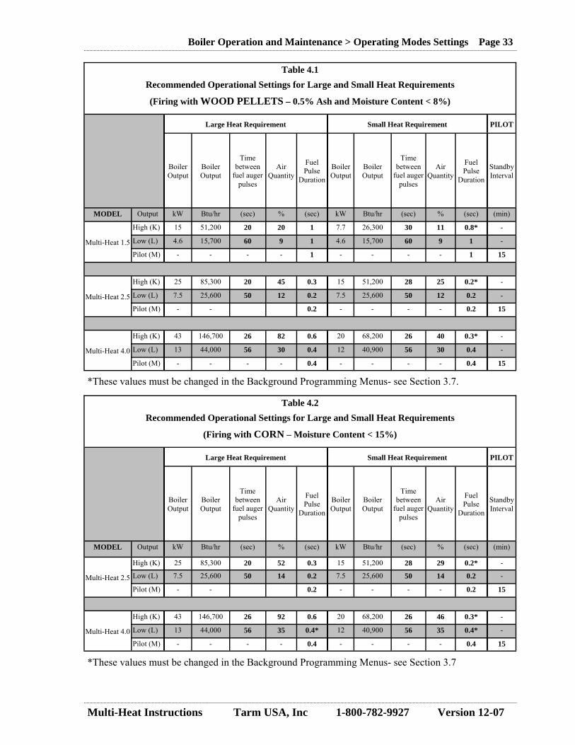
Table 4.1 Recommended Operational Settings for Large and Small Heat Requirements
(Firing with WOOD PELLETS – 0.5% Ash and Moisture Content < 8%)
Large Heat Requirement Small Heat Requirement PILOT
Boiler Output
Boiler Output
Time between
fuel auger pulses
Air Quantity
Fuel Pulse
Duration
Boiler Output
Boiler Output
Time between
fuel auger pulses
Air Quantity
Fuel Pulse
Duration
Standby Interval
MODEL Output kW Btu/hr (sec) % (sec) kW Btu/hr (sec) % (sec) (min)
Multi-Heat 1.5
High (K) 15 51,200 20 20 1 7.7 26,300 30 11 0.8* -
Low (L) 4.6 15,700 60 9 1 4.6 15,700 60 9 1 -
Pilot (M) - - - - 1 - - - - 1 15
Multi-Heat 2.5
High (K) 25 85,300 20 45 0.3 15 51,200 28 25 0.2* -
Low (L) 7.5 25,600 50 12 0.2 7.5 25,600 50 12 0.2 -
Pilot (M) - - 0.2 - - - - 0.2 15
Multi-Heat 4.0
High (K) 43 146,700 26 82 0.6 20 68,200 26 40 0.3* -
Low (L) 13 44,000 56 30 0.4 12 40,900 56 30 0.4 -
Pilot (M) - - - - 0.4 - - - - 0.4 15
Table 4.2 Recommended Operational Settings for Large and Small Heat Requirements
(Firing with CORN – Moisture Content < 15%)
Large Heat Requirement Small Heat Requirement PILOT
Boiler Output
Boiler Output
Time between
fuel auger pulses
Air Quantity
Fuel Pulse
Duration
Boiler Output
Boiler Output
Time between
fuel auger pulses
Air Quantity
Fuel Pulse
Duration
Standby Interval
MODEL Output kW Btu/hr (sec) % (sec) kW Btu/hr (sec) % (sec) (min)
Multi-Heat 2.5
High (K) 25 85,300 20 52 0.3 15 51,200 28 29 0.2* -
Low (L) 7.5 25,600 50 14 0.2 7.5 25,600 50 14 0.2 -
Pilot (M) - - 0.2 - - - - 0.2 15
Multi-Heat 4.0
High (K) 43 146,700 26 92 0.6 20 68,200 26 46 0.3* -
Low (L) 13 44,000 56 35 0.4* 12 40,900 56 35 0.4* -
Pilot (M) - - - - 0.4 - - - - 0.4 15
*These values must be changed in the Background Programming Menus- see Section 3.7.
*These values must be changed in the Background Programming Menus- see Section 3.7

Multi-Heat Instructions Tarm USA, Inc 1-800-782-9927 Version 12-07
Boiler Operation and Maintenance > Fuel Monitoring and Filling Page 34
4.4 Fuel Monitoring and Filling Fuel level in the hopper can only be checked by opening the hopper cover. Filling the hopper should be completed before it becomes empty for, uncovering the auger during operation increases the risk of burn-back. The fuel hopper can be refilled when the boiler is in operation. When the fuel hopper cover is opened, the fuel auger will not function, so it is necessary to complete the refilling within ap-proximately ten minutes to avoid the possibility of extinguishing the fire in the combustion chamber. When filling the fuel hopper, check the fuel hopper lid gasket and check that no fuel remains on the top of the fuel hopper that may prevent the fuel hopper lid from closing tightly. The hopper lid seal must be airtight, and should be checked regularly (monthly). Store fuel under cover, out of the elements. DO NOT STORE FUEL CLOSER THAN THE RE-QUIRED CLEARANCES TO COMBUSTIBLES (see Section 3.1.3) OR WITHIN THE SPACE RE-QUIRED FOR LOADING, ASH REMOVAL AND OTHER ROUTINE MAINTENANCE OPERA-TIONS.
If ventilation fans are used in the fuel storage area, they must be installed so as not to create negative pressures in the room where the boiler is located. 4.5 Switching between Wood Pellets and Corn When firing the 2.5 or 4.0 with corn, the fuel auger extension (supplied with the boiler (Fig. 4.2)) must be installed to help break up clinkers that can form in the combustion chamber. Use of a high temperature thread lubricant (such as “Anti-Seize”) on the auger extension is recommended to make removal easier. Note that the auger extension is reverse (left-hand) threaded. When the auger extension has shown extensive wear it should be replaced to prevent damage to the auger threaded shaft. If the corn is very corrosive, limestone can be added to the corn.
Y = must be used N = not be used
The boiler has been tested and is approved only for use with corn with a moisture content <15% When changing fuel-type, the boiler operational settings must be changed. Refer to the tables in Sec-tion 4.3.
Table 4.5 Equipment / Fuel Requirements for Multi-Heat Boilers
Wood Pellets Corn
Fuel Auger Refractory Extension N Y
Auger Extension
Fig. 4.2
NOTE
Usage of fuel types other than low ash wood pellets and corn can result in problematic operation, more work for the user, and increased fuel consumption. Further, usage of fuel types other than wood pellets and corn could cause potentially dangerous situations.
☼
WARNING
Risk of Fire or Explosion – Do not burn garbage, gasoline, engine oil, other flammable liquids or inappropriate materials in this boiler.

Multi-Heat Instructions Tarm USA, Inc 1-800-782-9927 Version 12-07
Boiler Operation and Maintenance > Starting the Boiler Page 35
4.6 Starting the Boiler Ensure the following before initial boiler firing or after a long shutdown period:
• There is sufficient water in the boiler and heating system. • The pressurized domestic cold water supply is connected to the back burn safety flood valve
and overheat coil and that all supply valves are opened. (See section 5.2 - Back Burn Safety Flood Valve and Section 5.4 – Overheat Cooling Coil).
• The combustion chamber refractory arch (item 9, fig. 1.1) is pushed fully back into position and wood shipping wedges are removed.
• The fuel hopper lid is fully closed, making the hopper air-tight. The built-in micro-switch pre-vents the fuel feed auger from running with an open lid.
• That air flow and fuel settings as indicated in Section 4.3 of this manual are programmed. Follow this procedure for igniting a boiler fueled by wood pellets: 1. The ON/OFF button (E) is OFF. Press button (G) feeding wood pellet fuel so that there is a
pile of about 5-6 handfuls inside the combustion chamber. 2. Pour a small quantity of gelled alcohol fire starter on the fuel and ignite (various wax impreg-
nated sawdust and wood chip fire starter products also work very well). 3. Ignite the pile with a match or a barbeque lighter. 4. Turn the ON/OFF button (E) to ON. 5. Push the two fan buttons (K and L) to start blower (auger will not operate in this mode). 6. Close doors 7. After the fire is ignited (about 5 minutes) set the control to full time low as explained on page
30 by pushing operation mode button (C). Let the smoke temperature reach 100º C. 8. Upon reaching 100º C, the boiler can be switched to automatic mode.
For igniting a boiler fueled by corn, 5-6 handfuls of easily combustible material (such as wood pellets) must be added to the mixture of corn to start combustion. Then follow the above instructions to ignite the mixture.
4.7 Routine Monitoring Tarm USA, Inc. strongly recommends that the owner/ system operator monitor the boiler daily when in operation. Regular monitoring by the owner/ system operator creates familiarity with the operation of the boiler and an ability to predict when cleaning and fuel filling will be necessary. Items to check daily are:
• Check fuel in the fuel hopper and fill as necessary. • Check ash level in the combustion area and remove as necessary. • Check ash level in heat exchanger area of the boiler, and clean when necessary. • Check boiler supply water temperature. Make sure it is near the water set-point. • Check boiler return water temperature. Make sure it is >60ºC (140ºF). • Check smoke temperature. Make sure it is within the operating guidelines below.
WARNING
DO NOT OVERFIRE. Do not attempt to feed in more fuel than the automatic feeding allows. If the chimney connector glows, you are over-firing the boiler.
Do not operate with fuel loading or ash removal doors open. Never leave the boiler with an open hopper cover as this can eventually lead to a burn back in the auger feed tube.
Do not use gasoline, kerosene or other flammable liquids to start or maintain a fire in your boiler. Serious burns and property damage may result.
Do not add more gelled alcohol or liquid fire starter after combustion starts.

Multi-Heat Instructions Tarm USA, Inc 1-800-782-9927 Version 12-07
Boiler Operation and Maintenance > Ash Removal Page 36
Smoke Temperature Guidelines are: • The boiler should not be operated with smoke temperature >220°C (428°F). • The boiler should be operated to ensure that the smoke temperature does not fall so low that
condensation is formed in the chimney. This temperature is dependent on the chimney’s di-ameter and insulation. If chimney condensation presents a problem, several turbulators can be removed from the boiler heat exchanger tubes to raise flue gas temperatures and counteract the condensation. Note: when turbulators are removed, the combustion efficiency will decrease and fuel consumption will increase!
• When using corn, the flue gas must be >140°C (284°F). • If the flue gas temperature is <100° C (212°F) for more than 30 minutes, an alarm (A-1) will
be initiated. Safely Opening the Doors:
• When opening the doors, one should stand with the doors between you and the boiler interior. • Crack open the door approximately 1 inch. - Wait for approximately 20 seconds, then open the
door slowly.
Wood pellets composed of pure wood residues produce comparatively little ash. Corn is a more diffi-cult fuel to manage due to its higher content of non-combustible constituents, which form ash and cin-ders. The combustion quality can vary greatly, depending on growing and harvesting conditions, chemical composition, and final moisture content when burned. Poor quality fuel gives more prob-lematic operation. 4.8 Ash Removal Removing ash and cinders from the combustion chamber should be done as needed (Fig. 4.2). The frequency of removal is dependent on the ash content of the fuel and the rate of fuel consumption.
Multi-Heat 1.5 and 4.0: The boiler is not equipped with an internal ash pan. An external pan can be purchased as an accessory, to be used for removing the ash and cinders from the combus-tion chamber. Ash and cinder removal should be done in LOW, STANDBY, or when the fire is extin-guished. In HIGH operating mode, hot embers are blown to the front of the combustion area against the lower door, making cleaning problematic. A specially shaped shovel tool provided with the boiler is used to remove the ash from the combustion chamber. It is desirable to leave a layer of ash at the base of the combustion chamber approximately level with the lower air holes to achieve effective combustion.
Important: Periodically remove any buildup of dark, tar-like residue forming at the base of the com-bustion area to the sides and below the entrance of the fuel auger. Use the shovel while the combus-tion area is still hot to remove residue. Vigorous use of the shovel may be required. Multi-Heat 2.5: The boiler is equipped with two ash pans, one of which one is placed in the combustion chamber im-mediately inside of the lower door.
Ashes should be placed in a metal container with a tight fitting lid. The container should be placed on a noncombustible floor or on the ground, well away from all combustible materials, pending final dis-posal. If the ashes are disposed of by burial in soil or otherwise locally dispersed, they should be re-tained in the closed container until all cinders have been thoroughly cooled.
Fig. 4.2
WARNING
The ash pan and cleaning tools can be very hot and cause burns! Use appropriate protective gloves!

Multi-Heat Instructions Tarm USA, Inc 1-800-782-9927 Version 12-07
Boiler Operation and Maintenance > Extinguishing the Boiler Page 37
4.9 Extinguishing the Boiler To extinguish the fire in the combustion area of the boiler, set the ON/OFF button (E) to OFF. Leave the boiler circulator ON to circulate residual heat through the boiler. To ensure that cinders and live coals do not ignite the fuel in the auger tube, it is necessary to physically separate them from the un-burned fuel there and move them to the front of the combustion area. After this is done, cold water from a spray bottle can be used to wet the fuel in the auger tube area and the metal faces under the re-fractory tunnel.
4.10 Routine Cleaning Cleaning tools are supplied with the boiler:
• Heat exchanger tube cleaning brush. • Shovel tool for ash removal. • Turbulator crank handle (for 1.5 and 4.0)
Intervals between cleaning depend upon the type, quality, and quantity of fuel used A guideline for boilers burning wood pellets follows:
• Ash removal: every 2 - 5 days based on fuel consumption. • Cleaning heat exchanger tubes and walls: every 4 - 15 days based on fuel consumption.
Burning corn requires more frequent removal of ashes and cleaning than burning wood pellets. A guideline for boilers burning corn follows:
• Ash removal: every 1 - 3 days based on fuel consumption. • Heat exchanger tubes and walls: every 3 - 15 days based on fuel consumption.
Frequent cleaning of the boiler guarantees optimal output, good operation of the boiler, and reasonable refractory life.
Heat exchanger tubes and boiler walls require cleaning to remove the buildup of fine ash that, over time, reduces the heat transfer efficiency of the boiler and leads to higher flue gas temperatures. Cleaning is performed after the boiler is extinguished and proceeds from the top of the boiler to the bottom. Clean the heat exchanger as follows:
1) Set the ON/OFF button to OFF. 2) Extinguish the fire and allow the boiler to cool. 3) Open the upper cleaning door. 4) Wearing gloves, remove the turbulators from the heat exchanger tubes. 5) Clean the face of the heat exchanger tubes and walls of the boiler using a stiff
bristled brush.
WARNING
It is important to completely extinguish combustion in the area under the combustion chamber refractory, since a few hot embers can reignite the fuel in the auger tube and lead to a burn-back event.
CAUTION
Do not use cleaning chemicals inside the boiler, as they can cause premature wear on the refrac-tory's, joints, and probes, and damage the boiler metal surfaces.
☼

Multi-Heat Instructions Tarm USA, Inc 1-800-782-9927 Version 12-07
Boiler Operation and Maintenance > Power Outages Page 38
6) Using the tube cleaning brush, clean the heat exchanger tubes by running the brush all the way through each tube, rotating the brush and pulling it back through. Two full passes (in and out being one pass) with the cleaning brush are typically sufficient to clean the entire surface of each heat exchanger tube.
7) The turbulators should be brushed off to remove fly ash and replaced into the heat exchanger tubes.
8) Ash should be cleaned off of the shelf below the upper cleaning door. An ash vacuum works best for this job.
9) Ash should be removed from the top of the combustion chamber arch through the lowest cleaning door and from the combustion chamber bed.
10) Using a scraping tool or wire brush, remove the ash adhering to the interior metal surfaces of the boiler.
While cleaning the boiler check that the gaskets on the lower and upper doors are in good condition and are not a source of any air leaks. Intermediate Heat Exchanger Cleaning – Multi-Heat 1.5 & Multi-Heat 4.0 The 1.5 and 4.0 boilers are equipped with twisted or spiral turbulators. The turbulator crank handle can be used to spin the turbulators regularly when the user notices a build up of ash in the heat ex-changer tubes or an increase in the smoke temperature. By cranking each turbulator approximately fifteen turns, the ash buildup is moved back into the smoke box at the rear of the heat exchanger. Cleaning of the Ash Cleanout During boiler operation, ash accumulates in the cleanout area at the rear of the heat exchange tubes
(Fig 4.3), and should be removed during every other cleaning of the boiler. Cleaning of the cleanout should be performed between steps 6) and 7) described above and would include: 1. Removal of one of the side panels from the Multi-Heat boiler. 2. Remove the ash cleanout cover (Item 17, Figure 1.1). 3. Remove ash from ash cleanout area, using a soot vacuum or rake. 4. Replace ash cleanout gasket and cover, and the side panel. Note: It may be helpful to use an ash vacuum designed and approved for use where hot embers may be present to vacuum out the cleanout and other areas of the boiler. After long time use, primary air holes on the bottom of the combus-tion area should be checked to make sure that they are clear and func-tioning (Fig 4.4).
4.11 Power Outages The boiler will not operate in the event of a power failure. It is good practice to extinguish the boiler and pull the fuel away from the back of the combustion chamber. Do not attempt to hand feed pellets or corn into the boiler during a power outage. Do not open the upper or lower doors (except to extin-guish the boiler).
Fig. 4.3
Holes
Fig. 4.4

Multi-Heat Instructions Tarm USA, Inc 1-800-782-9927 Version 12-07
Boiler Operation and Maintenance > Off-season Shutdown Procedures Page 39
4.12 Off-season Shutdown Procedures If the boiler will not be fired for an extended time period the boiler should be protected from corrosion by taking the following steps: 1. Clean all interior surfaces of the boiler, including the heat exchanger tubes. 2. Completely remove all ash deposits and fuel from the boiler combustion area with a vacuum cleaner. 3. Remove and clean the smoke pipe connecting the boiler to the chimney. 4. Do not replace the smoke pipe (store it near the boiler). 5. Stuff insulation into the flue outlet of the boiler to block off air passing through the boiler. Keep all doors and air dampers closed. Hang a 15-25 watt light bulb inside the boiler combustion area if condensation starts to form anywhere inside the boiler. 4.13 Annual and Preventive Maintenance The chimney system should be inspected at least once every year and cleaned if necessary. Products of combustion will contain small particles of fly ash. Fly ash collects in the chimney system and re-stricts the flow of the flue gases. Incomplete combustion, such as occurs during startup, shutdown, or prolonged STANDBY operation of the boiler, can lead to soot formation in the chimney system.
The boiler pressure relief valve should be flushed at least once per year. Follow the manufacturer’s instructions on the tag attached to the valve.
The thermal valves for burn-back suppression and over-heat cooling coil activation should be tested and inspected annually. The pressure in the burn back system should be checked at least once per year to verify the condition of the pressurized tank (which is pre set at 3 – 5 psi. without water content. With water supply attached pressure should be a minimum of 30 psi). The thermal valves can be function-tested by depressing the red buttons on top of the valves. This should cause water to flow through the valves (disconnect the thermal valve from the fuel auger tube before conducting this test). Sawdust or other fine waste from the fuel will accumulate at the bottom of the fuel hopper over time. It is necessary twice a year to empty the fuel hopper entirely to remove this sawdust or fine waste in the fuel hopper and along the fuel auger. This buildup of sawdust is particularly undesir-able since it increases the risk of a burn-back event. The seal around the fuel hopper lid and the gaskets on the cleanout panels on the sides of the hop-per must seal completely and be airtight. They should be checked regularly (at least once a year and after any burn-back event).
CAUTION
Before cleaning, remove the flue gas temperature sensor in the boiler flue collar so it is not bent or damaged during cleaning.
☼

Multi-Heat Instructions Tarm USA, Inc 1-800-782-9927 Version 12-07
Troubleshooting and Service > Alarms and Responses Page 40
5.0 Troubleshooting and Service 5.1 Alarms and Responses The control panel monitors boiler operating parameters. When these parameters are not within expected values, the control panel creates a visual and audible warning alarm. These alarms require immediate attention. When an alarm is activated, the control panel will flash with the identification code of the alarm and an audible high pitched noise is produced. Write down the alarm code shown on the control panel before taking action. Keep a written log of alarms with times, dates, and actions taken. (F) Alarm Reset Alarms are reset or cleared with this button. If there are no alarms present, the but-
ton is used in conjunction with other buttons to enter the programming menu (see below).
The alarms listed on the next page will appear on the display (A). Alarms begin-
ning with A can cause the boiler to shut down. They may require the owner/ sys-tem operator to troubleshoot and restart the boiler. Alarms beginning in F are for information and action but do not result in shut down. F alarms can be reset by pressing any key on the display.
Table 5.1 Alarm Summary
DISPLAY MEANING A-1 The fire in the combustion area is going out! The flue gas temperature has been
below 90ºC (194ºF) for more than 30 minutes while the boiler is in operation.
A-2 The boiler has overheated. Boiler supply water temperature has exceeded 100ºC (212ºF), causing the over heat aquastat (D) to switch off the blower and pellet auger. The aquastat can be reset after the supply water cools down (see Section 4.2)
OR Fuse F1 on the Stoker Power PC board has blown and must be replaced (replace with a 2.5 amp fuse if this happens)
OR The Stoker Control PC board has failed. (Very rare-contact Tarm USA, Inc.)
A-3 The fuel auger system is not operating correctly. The motor protector has switched off the pellet auger due to high current (possible stalling). It will reset itself and can be tried again. OR The Smoke Sensor has failed. OR Smoke Temperature is above 280ºC. Boiler needs to be cleaned.
A-4 Internal water temperature has significantly exceeded the set-point. Boiler supply water temperature has exceeded 94ºC (201ºF).
A-5 There has been an internal communication error between the control PC board and the program. Try restarting the boiler. Contact Tarm USA Inc
A-6 Not used in North America. A-7 Not used in North America. (Lambda is damaged) A-8 Not used in North America. A-9 Not used in North America. A-10 Not used in North America. A-11 Not used in North America.

Multi-Heat Instructions Tarm USA, Inc 1-800-782-9927 Version 12-07
Troubleshooting and Service > Burn-Back Suppression Page 41
5.2 Burn-Back Suppression A thermal burn-back safety flood valve is supplied with the boiler. The safety flood valve is installed on the boiler at the factory. The installer must connect the valve to the domestic cold water supply. If the temperature on the outside of the fuel auger tube exceeds 100°C (212ºF), the valve will be open and water will enter the tube, extinguishing any combustion causing the condition. This is called a burn-back event. When the temperature decreases, the thermal valve will close, and the flow of water will stop. The control panel does not directly sense a burn-back event and there is no specific alarm for it. How-ever, the water in the auger tube extinguishes the fire, causing an A1 alarm. After a burn-back event, the boiler will normally require cleaning and restarting.
• The combustion chamber must be dried. • Remove the water and empty the air chamber by removing the “drain screw” (Situated behind
the lowest front plate (Fig. 5.1 and 5.2)). Remember to reinstall the “drain screw” after the water is drained out.
• Remove all the fuel from the auger tube and hopper and check for any hot embers. (On the Model 2.5 and 4.0 there are side access panels (Fig 5.3)).
• Before restarting up the boiler, determine why the burn-back event happened. • Check the thermal valve for proper operation.
A burn-back event can be caused by leaving the hopper door open, air leakage into the hopper at the hopper or feed tube gaskets, a defective leaking thermal valve, or the boiler has been in stand-by for a long period of time. While the burn back suppression valve will have normally extinguished any auger burn-back, if a burn-back is suspected, it is good practice to open the hopper door carefully. Smoke and steam may be pre-sent. If any hopper surfaces are hot, there may be a fire present in the hopper. KEEP THE HOPPER LID CLOSED. CALL THE FIRE DEPARTMENT.
A-13 The boiler supply water temperature probe is defective and must be replaced. (Open-circuited & measuring greater than 120ºC (248ºF)).
A-14 The flue gas temperature probe is defective and must be replaced. (Short-circuited & measuring < -30ºC (-22ºF) for at least 4 minutes).
A-15 The flue gas temperature probe is defective and must be replaced. (Open-circuited & measuring >350ºC (662ºF)).
F-1 The boiler needs cleaning, especially the heat exchanger tubes. The flue gas tem-perature exceeded 240ºC (464ºF) more than three times.
F-2 Not used in North America F-3 Not used in North America F-4 The boiler return water temperature probe is defective and must be replaced.
(Short-circuited & measuring < -35ºC (-31ºF)).
F-5 The boiler return water temperature probe is defective and must be reinstalled or replaced. (Open-circuited & measuring > 120ºC (248ºF)).
- - - The Prom on the control board needs to be changed.
A-12 The boiler supply water temperature probe is defective and must be replaced. (Short-circuited & measuring < -40ºC (-40ºF)).
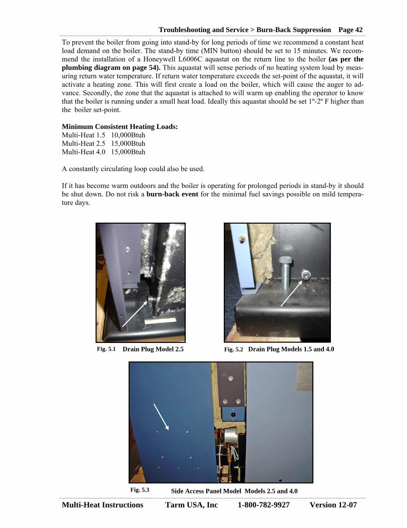
Multi-Heat Instructions Tarm USA, Inc 1-800-782-9927 Version 12-07
Troubleshooting and Service > Burn-Back Suppression Page 42
To prevent the boiler from going into stand-by for long periods of time we recommend a constant heat load demand on the boiler. The stand-by time (MIN button) should be set to 15 minutes. We recom-mend the installation of a Honeywell L6006C aquastat on the return line to the boiler (as per the plumbing diagram on page 54). This aquastat will sense periods of no heating system load by meas-uring return water temperature. If return water temperature exceeds the set-point of the aquastat, it will activate a heating zone. This will first create a load on the boiler, which will cause the auger to ad-vance. Secondly, the zone that the aquastat is attached to will warm up enabling the operator to know that the boiler is running under a small heat load. Ideally this aquastat should be set 1º-2º F higher than the boiler set-point. Minimum Consistent Heating Loads: Multi-Heat 1.5 10,000Btuh Multi-Heat 2.5 15,000Btuh Multi-Heat 4.0 15,000Btuh A constantly circulating loop could also be used. If it has become warm outdoors and the boiler is operating for prolonged periods in stand-by it should be shut down. Do not risk a burn-back event for the minimal fuel savings possible on mild tempera-ture days.
Fig. 5.3
Fig. 5.1 Fig. 5.2 Drain Plug Model 2.5 Drain Plug Models 1.5 and 4.0
Side Access Panel Model Models 2.5 and 4.0
Multi-Heat Instructions Tarm USA, Inc 1-800-782-9927 Version 12-07
Troubleshooting and Service > Combustion Problems Page 43
5.3 Combustion Problems Chimney fires are caused when an excessive buildup of creosote in the chimney connector pipe or the chimney is ignited by a racing fire, or when a burning piece of material is swept out of the firebox into the chimney. If you have a chimney fire, you will hear a roaring sound in your chimney, almost like a jet airplane. In addition, sparks may be seen flying from the chimney outside the house. Chimney fires can set fire to the interior of your house or your roof. They are potentially very dangerous, and the following procedure should be followed if you think you have a chimney fire:
1. Call the fire department. 2. Shut all doors and close all air inlets on your boiler. 3. Evacuate your house. 4. If possible, wet your entire roof with a garden hose.
Chimney fires can be avoided by following the recommendations in this manual for minimizing ash formation, by maintaining your chimney in good condition, and by cleaning your chimney regularly. A chimney fire should never happen with a Multi-Heat boiler!
5.4 Heat Transmission Issues If the circulator pump “gurgles”, this means that there is air in the system. Purge the boiler and the entire heat distribution system of all air. During air purging, the pump must be off. If the pump “howls” or “wails” this can be because there is insufficient water in the system. The pump’s bearings are lubricated by water, and they will be ruined if there is insufficient water. To remove heat quickly from an overheated boiler, an overheat cooling coil is installed in the boiler water jacket. Upstream of the cooling coil, a thermal valve is installed and connected to pressurized domestic cold water supply (minimum ½” diameter). The thermal valve opens when a fixed sensor installed in the boiler water jacket measures 100ºC (212ºF). Cold water passes once through the coil, removing heat from the boiler. The thermal valve closes when the boiler water temperature decreases. Water which passes through the coil is very hot and is exhausted outside the boiler to a floor drain. The control panel does not directly sense an overheat cooling coil activation and there is no specific alarm for it. It is very likely, however, that the boiler will independently generate an A2 or A4 alarm. An overheat cooling coil activation is an indication that no heat is being removed from the boiler. The owner/ system operator should determine the cause and correct the condition (or extinguish the boiler).
5.5 Technical Assistance Tarm USA, Inc. will provide free telephone technical assistance at the number below. 5.6 Service and Repair Tarm USA, Inc. maintains a service parts inventory. Ask for assistance at the number below. 5.7 Troubleshooting Guide The chart on the next page covers common boiler problems.

Multi-Heat Instructions Tarm USA, Inc 1-800-782-9927 Version 12-07
Troubleshooting and Service > Troubleshooting Guide Page 44
2/5/
2007
M
H T
RO
UB
LESH
OO
TIN
G G
UID
E
TYPE
PR
OB
LEM
R
OO
T C
AU
SE
DIA
GN
OSI
S C
UR
E SA
FETY
Fr
eque
nt B
UR
NB
AC
KS
Air f
low
pat
h th
ru a
uger
tube
to h
oppe
r In
spec
t all
gask
eted
are
as in
hop
per
Tigh
ten
bolts
and
silic
on a
t edg
es
Auge
r mot
or is
failin
g Se
e Au
ger s
ectio
n
Fire
mig
ratio
n fro
m lo
ng p
erio
ds in
sta
ndby
M
onito
r boi
ler o
pera
ting
mod
es/ t
empe
ratu
re c
reep
Ex
tingu
ish
unit/
pro
vide
freq
uent
load
to u
nit/
adju
st s
tand
by p
rogr
am
Fire
mig
ratio
n du
e to
fine
dus
t in
auge
r tub
e In
spec
t aug
er tu
be a
nd h
oppe
r for
woo
d du
st
Cle
an h
oppe
r and
aug
er tu
be s
ever
al ti
mes
per
hea
ting
seas
on
Bu
rn-b
ack
Ther
mal
VA
LVE
leak
s in
to a
uger
tube
Th
erm
al v
alve
def
ectiv
e, fa
iled,
or o
pen
by d
ebris
In
spec
t val
ve
Fix
or re
plac
e va
lve
B
UR
NB
AC
K S
YSTE
M n
ot o
pera
ting
corr
ectly
N
o w
ater
sup
ply
Che
ck u
pstre
am v
alve
s, lo
osen
fitti
ngs
Turn
on
supp
ly, p
urge
air
Ther
mal
val
ve d
efec
tive,
faile
d, o
r obs
truct
ed
Insp
ect a
nd te
st v
alve
Fi
x or
repl
ace
valv
e, re
mov
e ob
stru
ctio
n
Ther
mal
val
ve p
robe
mis
loca
ted
Che
ck p
robe
loca
tion
Fix
FUN
CTI
ON
FA
N ru
ns a
t hig
h sp
eed/
con
trol p
anel
non
resp
onsi
ve
Con
trol P
CB
failu
re
See
A-2
alar
m s
ectio
n R
epla
ce c
ontro
l PC
B, i
f fus
e F1
was
ok
& C
ON
TRO
L FA
N d
oes
not o
pera
te o
r ope
rate
s er
ratic
ally
N
o po
wer
at f
an
Che
ck th
at fa
n ca
ble
is p
lugg
ed in
/ mea
sure
sup
ply
volta
ge a
t pw
r PC
B
Plug
in/ d
eter
min
e if
cabl
e or
PC
B is
bad
and
repl
ace
Fan
failu
re
Fan
is n
oisy
/ unp
lug
fan
cabl
e an
d ch
eck
supp
ly v
olta
ge a
t plu
g R
epla
ce fa
n an
d fla
nge
Prog
ram
min
g is
wro
ng
Che
ck p
rogr
amm
ing
agai
nst m
anua
l R
eset
pro
gram
min
g to
mat
ch m
anua
l
F1 fu
se is
blo
wn
Test
bot
h fu
ses
on p
ower
PC
B
Upg
rade
F1
fuse
to 2
.5A/
ins
tall
RIB
rela
y to
run
circ
ulat
or C
1
Type
A a
larm
is p
rese
nt
See
alar
m s
ectio
n
A
UG
ER d
oes
not o
pera
te o
r ope
rate
s er
ratic
ally
H
oppe
r cov
er o
pen
or m
icro
-sw
itch
faile
d C
heck
hop
per c
over
and
test
sw
itch
(sho
rt ci
rcui
t whe
n sw
itch
depr
esse
d)
Mic
ro-s
witc
h m
ust b
e fu
lly d
epre
ssed
/ rep
lace
if d
efec
tive
Auge
r sha
ft is
sei
zed
C
heck
for b
urn-
back
sup
pres
sion
, che
ck fo
r deb
ris b
lock
age
in h
oppe
r Fr
ee u
p au
ger s
haft
Smok
e te
mp
exce
eded
260
/aug
er s
topp
ed
Che
ck s
mok
e te
mp
on d
ispl
ay
Cle
an b
oile
r, au
ger w
ill be
on-
line
whe
n sm
oke
tem
p is
bel
ow 2
30
F1 fu
se is
blo
wn
See
Fan
sect
ion
Inco
min
g po
wer
pro
blem
M
easu
re v
olta
ge in
to p
ower
PC
B (2
40V
at J
2 po
ints
1 &
2)
Trou
bles
hoot
and
cor
rect
Smok
e te
mp
sens
or fa
iled
Cle
an &
test
sen
sor (
LED
D5
on p
ower
PC
B is
on
whe
n ok
) R
epla
ce s
enso
r (lif
t wire
s at
J5,
resi
stan
ce s
houl
d be
1-2
kilo
hms)
Mot
or p
rote
ctio
n pr
oble
m
Smel
l tes
t, ch
eck
& ad
just
set
tings
& re
set,
chec
k fo
r loo
se w
ires,
lift
cont
ract
or w
ire &
use
it to
run
the
mot
or m
anua
lly
Rep
lace
com
pone
nts
and
rew
ire
Wiri
ng p
robl
em
Che
ck fo
r loo
se w
ire, l
ift m
otor
cab
le w
ires
at b
oth
ends
& te
st re
sist
ance
R
epla
ce c
able
Pow
er P
CB
is d
efec
tive
Che
ck fo
r loo
se w
ires,
che
ck fu
ses,
rese
t boi
ler &
che
ck L
ED s
tatu
s on
boa
rd
Rep
lace
boa
rd
Auge
r mot
or is
failin
g M
otor
noi
sy, m
ore
puls
es n
eede
d pe
r rev
, per
iods
of p
oor p
erfo
rman
ce
Rep
lace
mot
or
A
-1 A
LAR
M (s
mok
e te
mp
belo
w 1
00 lo
ng ti
me)
Fi
re is
out
in c
ombu
stio
n ch
ambe
r C
heck
for f
ire in
boi
ler,
chec
k th
at fa
n an
d au
ger f
unct
ion,
che
ck fo
r fue
l in
hopp
er
Re-
fire
boile
r
Burn
-bac
k ev
ent o
ccur
red
Che
ck fo
r bur
n-ba
ck s
uppr
essi
on
Free
aug
er s
haft
Hop
per c
over
ope
n or
mic
ro-s
witc
h fa
iled
Che
ck h
oppe
r cov
er a
nd te
st s
witc
h (s
hort
circ
uit w
hen
switc
h de
pres
sed)
M
icro
-sw
itch
mus
t be
fully
dep
ress
ed/ r
epla
ce if
def
ectiv
e
Smok
e te
mp
exce
eded
260
/aug
er s
topp
ed
Che
ck s
mok
e te
mp
Cle
an b
oile
r, au
ger w
ill be
on-
line
whe
n sm
oke
tem
p is
bel
ow 2
30
Smok
e te
mp
sens
or fa
iled
Cle
an &
test
sen
sor (
LED
D5
on p
ower
PC
B is
on
whe
n ok
) R
epla
ce s
enso
r (lif
t wire
s at
J5,
resi
stan
ce s
houl
d be
1-2
kilo
hms)
A
-2 A
LAR
M (o
verh
eat a
quas
tat t
rippe
d)
Tem
pera
ture
cre
ep in
sta
ndby
mod
e O
bser
ve s
uppl
y w
ater
tem
p in
sta
ndby
mod
e, c
heck
set
-poi
nt ,c
heck
dam
per
Adju
st p
rogr
amm
ing
for s
tand
by m
ode,
adj
ust s
et-p
oint
, adj
ust d
ampe
r
Back
up b
oile
r set
-poi
nt to
o hi
gh
Back
up b
oile
r cyc
les
frequ
ently
, pel
let b
oile
r sup
ply
tem
p m
uch
high
er th
an s
et-p
oint
Ad
just
bac
kup
boile
r set
-poi
nt
Aqua
stat
is d
efec
tive
or m
iss-
wire
d C
heck
& te
st a
quas
tat (
shou
ld b
e sh
ort c
ircui
t whe
n co
oled
& re
set)
Fix
wiri
ng/ r
epla
ce a
quas
tat
Con
trol P
CB
is d
efec
tive
Fan
runs
hig
h sp
eed/
con
trol p
anel
non
-res
pons
ive,
che
ck fl
at c
able
, che
ck fu
se F
1 R
epla
ce c
ontro
l PC
B if
fuse
F1
was
ok
See
abov
e "A
uger
doe
s no
t ope
rate
…"
A
-3 A
LAR
M (a
uger
mot
or o
verlo
ad tr
ip)
See
abov
e "A
uger
doe
s no
t ope
rate
…"
See
abov
e
Smok
e te
mp
sens
or fa
iled
Cle
an &
test
sen
sor (
LED
D5
on p
ower
PC
B is
on
whe
n ok
) R
epla
ce s
enso
r (lif
t wire
s at
J5,
resi
stan
ce s
houl
d be
1-2
kilo
hms)
Smok
e te
mp
abov
e 28
0- n
eeds
cle
anin
g C
heck
for h
igh
smok
e te
mp,
che
ck b
oile
r cle
anlin
ess
Cle
an b
oile
r
A
-4 A
LAR
M (s
uppl
y w
tr te
mp
abov
e 90
) Te
mpe
ratu
re c
reep
in s
tand
by m
ode
See
A-2
alar
m
Back
up b
oile
r set
poin
t too
hig
h Se
e A-
2 al
arm
Supp
ly w
ater
tem
p se
nsor
faile
d C
heck
& te
st s
enso
r (lif
t wire
s at
J5,
resi
stan
ce s
houl
d be
1-2
kilo
hms)
R
epla
ce s
enso
r
A
-5 A
LAR
M (c
omm
unic
atio
n er
ror i
n pr
ogra
m)
Pow
er o
r con
trol P
CB
faile
d Se
e ab
ove
for a
uger
, fa
n an
d A-
2 al
arm
Cab
le b
etw
een
PCBs
mis
s-co
nnec
ted
Che
ck c
onne
ctio
n &
rem
ake
Rep
lace
flat
cab
le
F-
1 A
LAR
M (s
mok
e te
mp
abov
e 24
0/ 3
tim
es)
Boile
r nee
ds c
lean
ing
Che
ck b
oile
r cle
anlin
ess
Cle
an b
oile
r
Smok
e te
mp
sens
or fa
iled
See
A-1
alar
m
Rep
lace
sen
sor
Fig.
5.6

Multi-Heat Instructions Tarm USA, Inc 1-800-782-9927 Version 12-07
Troubleshooting and Service > Troubleshooting Guide Page 45
D2 D3
D7
D1
D1
D5
D9
D11
D13
5.8 Power PCB Board Troubleshooting Light diodes on power PCB board can be used to trouble shoot.
LED Color Function Description
D2 Yellow Alarm Relay On at Alarm
D3* Green 12VDC On when 12VDC supply is OK
D5* Yellow Smoke Safety Relay Off, when flue temperature probe is not OK
D7* Yellow Door Switch Relay Off, when door to hopper is open
D9 Yellow Auger Reverse Relay On when Auger Moves in Reverse
D10** Yellow Auger Forward Relay On when Auger Moves Forward
D11* Yellow Oxygen Probe Relay Off when Oxygen Probe is Heated
D12 Yellow Pump Relay Off, when pump is on
D13** Red Thermal Failure Off, when over-heat circuit breaker trips at 100º C
PCB Trouble Shooting
* ON with normal PCB ** ON/OFF when auger cycles

Multi-Heat Instructions Tarm USA, Inc 1-800-782-9927 Version 12-07
Data and Drawings > Measurement Data Page 46
6.0 Data and Drawings 6.1 Measurement Data 1 2 3
4
1
Description Units MH 1.5 MH 2.5 MH 4.0
1. Flue Pipe, External Diameter inches 5.125 5.875 5.875
2. Return Connection inches 1 1 1
3. Supply Connection inches 1 1 1
4. Burn-back Protection Connection inches .5 .5 .5
L1. Measurement inches 23 23 27.5
L2. Measurement inches 7.750 8.5 8.5
L3. Measurement inches 19.5 24.250 24.250
L4. Measurement inches 56.5 62.5 66.67
L5. Measurement inches 14.2 11.5 15.875
L6. Measurement inches 5 5 5
L7. Measurement inches 6.5 9.750 9.67
H1. Measurement inches 39.750 50.375 50.375
H2. Measurement inches 45.875 50.375 50.375
B3. Measurement inches 19.750 23.625 23.625
Fig. 6.1
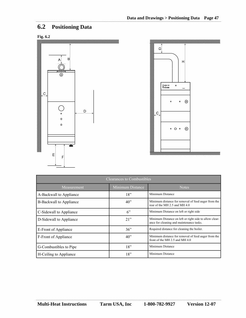
Multi-Heat Instructions Tarm USA, Inc 1-800-782-9927 Version 12-07
Data and Drawings > Positioning Data Page 47
6.2 Positioning Data
Measurement Minimum Distance Notes
A-Backwall to Appliance 18” Minimum Distance
B-Backwall to Appliance 40” Minimum distance for removal of feed auger from the rear of the MH 2.5 and MH 4.0
C-Sidewall to Appliance 6” Minimum Distance on left or right side
D-Sidewall to Appliance 21” Minimum Distance on left or right side to allow clear-ance for cleaning and maintenance tasks.
E-Front of Appliance 36” Required distance for cleaning the boiler.
F-Front of Appliance 40” Minimum distance for removal of feed auger from the front of the MH 2.5 and MH 4.0
Clearances to Combustibles
G-Combustibles to Pipe 18” Minimum Distance
H-Ceiling to Appliance 18” Minimum Distance
Fig. 6.2

Multi-Heat Instructions Tarm USA, Inc 1-800-782-9927 Version 12-07
Data and Drawings > Specification Data Page 48
6.3 Specification Data Technical Data Units MH 1.5 MH 2.5 MH 4.0
MEASUREMENTS
Depth- Boiler & Fuel Hopper- Total inches 56.5 62.2 66.7
Width- Boiler or Fuel Hopper inches 19.9 23.6 23.6
Height including smoke pipe stub inches 45.9 58.1 58.1
Fuel Hopper capacity Cu ft 7 12.7 12.7
Hopper Hatch dimensions (length x width) inches 15.8 X 15.8 20.5 X 20.5 20.5 X 20.5
Smoke Pipe Stub outside diameter inches 5.2 5.9 5.9
Weight- Empty lbs 750 1168 1279
Water Contents gallons 13.2 33 39.6
Distance behind Boiler for replacing worm conveyor inches 31.5 39.4 39.4
Distance in front of Boiler to fully open doors inches 19.7 23.7 23.7
Space around Hopper for service access inches 4 4 4
OPERATING DATA
Operating Temperature-Water Fº 140-185 140-185 140 - 185
Nominal Output-Wood Pellets or Corn Btu/hr 51,200 (pellets only) 85,300 146,700
Output at 30% (minimum)-Wood Pellets or Corn Btu/hr 15,700 (pellets only) 25,600 40,950
Approximate Output in Standby Btu/hr 1,700 (pellets only) 2,700 3,300
Smoke Temperature at Nominal Output-Wood Pellets -Corn
Fº Fº
302 -
356 392
356 392
Smoke Temperature at 30% Output-Wood Pellets - Corn
Fº Fº
212 -
230 239
230 239
Smoke Gas Volume at Nominal Output-Wood Pellets -Corn
Cu meters/hr Cu meters/hr
36 -
58 60
93 97
Fuel Consumption at Nominal Output-Wood Pellets -Corn
lbs/hr lbs/hr
7.5 -
12.6 13.2
22 24.3
Noise Level Db(A) <70 <70 <70
ELECTRICAL DATA
Boiler Power Requirement 240V-60Hz/15A 240V-60Hz/15A 240V-60Hz/15A
Electricity Consumption KW .3 .46 .46
Auger Motor KW .12 .37 .37
Blower W 90 90 90
Auger Motor Protection Setting Amps 1.1 2.3 2.3
PIPING DATA
Boiler Test Pressure psi 58 58 58
Cooling Coil Test Pressure psi 362 362 362
Boiler Relief Valve Setting psi 30 30 30
Supply & Return pipe stub size (male npt) inch 1 1 1
Minimum Boiler Loop size inch 1 1.25 1.25
Cooling coil & fire suppression connection size inch .5 .5 .5
Fill/ drain valve size inch .5 .5 .5
Pressure Drop for 10 degrees C temperature difference psi .067 .178 .435
Mixing Valve Opening Setting Fº 162 162 162
Internal Overheat Aquastat Setting Fº 212 212 212
Pellet length inch 0.2-0.8 0.2-0.8 0.2-0.8
Approximate moisture content % 8 8 8
WOOD PELLET DATA
Required Draft inch WC .04”-.1” .04”-.1” .04”-.1”
Safety Listings - UL 391-1995, CAN/CSA B366.1-M91,UL726, ANSI
Z21.13-200, CSA 4.9-M2000
UL 391-1995, CAN/CSA B366.1-M91,UL726, ANSI
Z21.13-200, CSA 4.9-M2000
UL 391-1995, CAN/CSA B366.1-M91,UL726, ANSI
Z21.13-200, CSA 4.9-M2000
Fig. 6.3
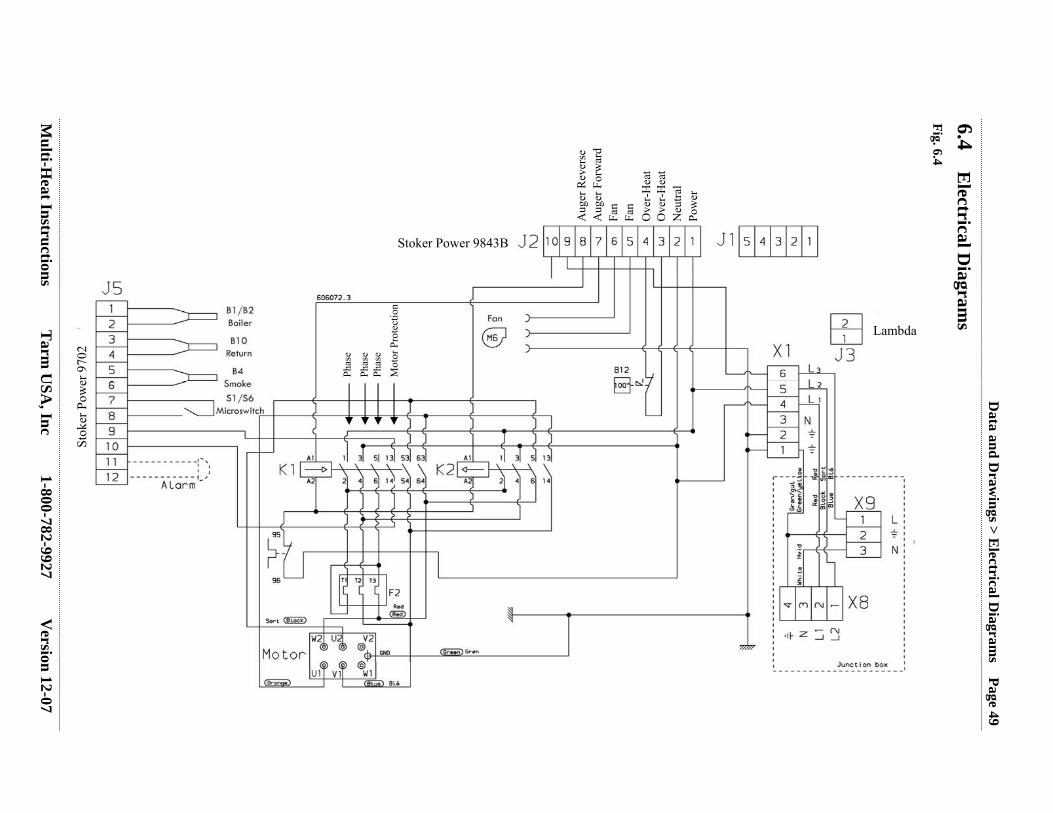
Multi-H
eat Instructions Tarm
USA
, Inc 1-800-782-9927 Version 12-07
Data and D
rawings > E
lectrical Diagram
s Page 49
6.4 E
lectrical Diagram
s
Fig. 6.4
Stoker Power 9843B
Stok
er P
ower
970
2
Aug
er R
ever
se
Aug
er F
orw
ard
Fan
Fan
Ove
r-H
eat
Ove
r-H
eat
Neu
tral
Pow
er
Phas
e
Phas
e Ph
ase
Mot
or P
rote
ctio
n
Lambda

Multi-Heat Instructions Tarm USA, Inc 1-800-782-9927 Version 12-07
Data and Drawings > Electrical Diagrams Page 50
Fig. 6.5

Multi-Heat Instructions Tarm USA, Inc 1-800-782-9927 Version 12-07
Data and Drawings > Electrical Diagrams Page 51
Fig. 6.6
T¹
T²
T³ X1
K1
K2
1 2 3 4 5 6 K3 F4
Top
Seen From Behind
B12
F1
F3
C1
C2
J5
J2
J4
Explanation for Electrical Diagram B12-Overheat Aquastat/Circuit Breaker (Tarm Part #08007) C1-Boiler Power Board (Tarm Part #210761) C2-Boiler control board (Tarm Part #210760) F1-Fuse 2.5A (Tarm Part #6F102). Protects fan and pump. F2-Fuse-Hard Wired. Protects heat shield on power board. F3-Fuse 1A (Tarm Part #100135). Protects transformer, which sends 24V to control board. F4-Motor Thermal (Tarm Part #210755 for Model 1.5 and #210785 for Model 2.5 and 4.0) J2-Power Terminal Block 230VDC J4-Connection Between Power and Control Print K1&K2-Control Relay (Tarm Part #210753) K3-Auxillary Control Relay (Tarm Part #210773) L1&L2-”Hot Leads” N-Neutral G-Ground T1-T3-Motor Connection X1-Terminal Block
L1 L2 L3
N G G
F2
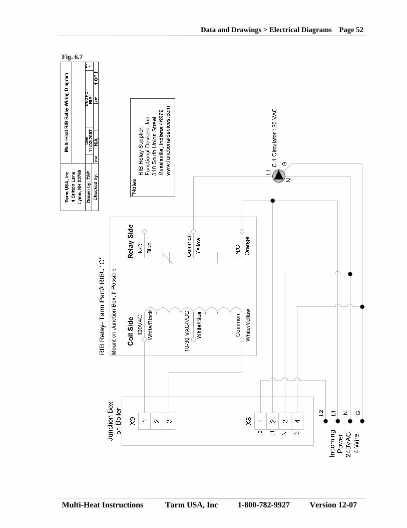
Multi-Heat Instructions Tarm USA, Inc 1-800-782-9927 Version 12-07
Data and Drawings > Electrical Diagrams Page 52
Fig. 6.7

Multi-Heat Instructions Tarm USA, Inc 1-800-782-9927 Version 12-07
Data and Drawings > Plumbing Diagrams Page 53
6.5 Plumbing Diagrams 6.51 Recommended Supply and Return Fittings
1” C X MIP Adapter
1” X 1” X 3/4” Tee
Pressure Relief Valve (supplied)
1/4” X 3/4” Bushing
Pressure and Temperature Gauge (supplied)
1” X 4” Nipple
*Note-All fittings should be black iron or copper.
3/4” Street Elbow 1” X 1” X 3/4” Tee
1” Close Nipple
1” BST Coupling (supplied)
1” C X MIP Adapter
1” Ø Supply 1” Ø Supply
HS Tarm Multi-Heat Boiler
Fig. 6.6
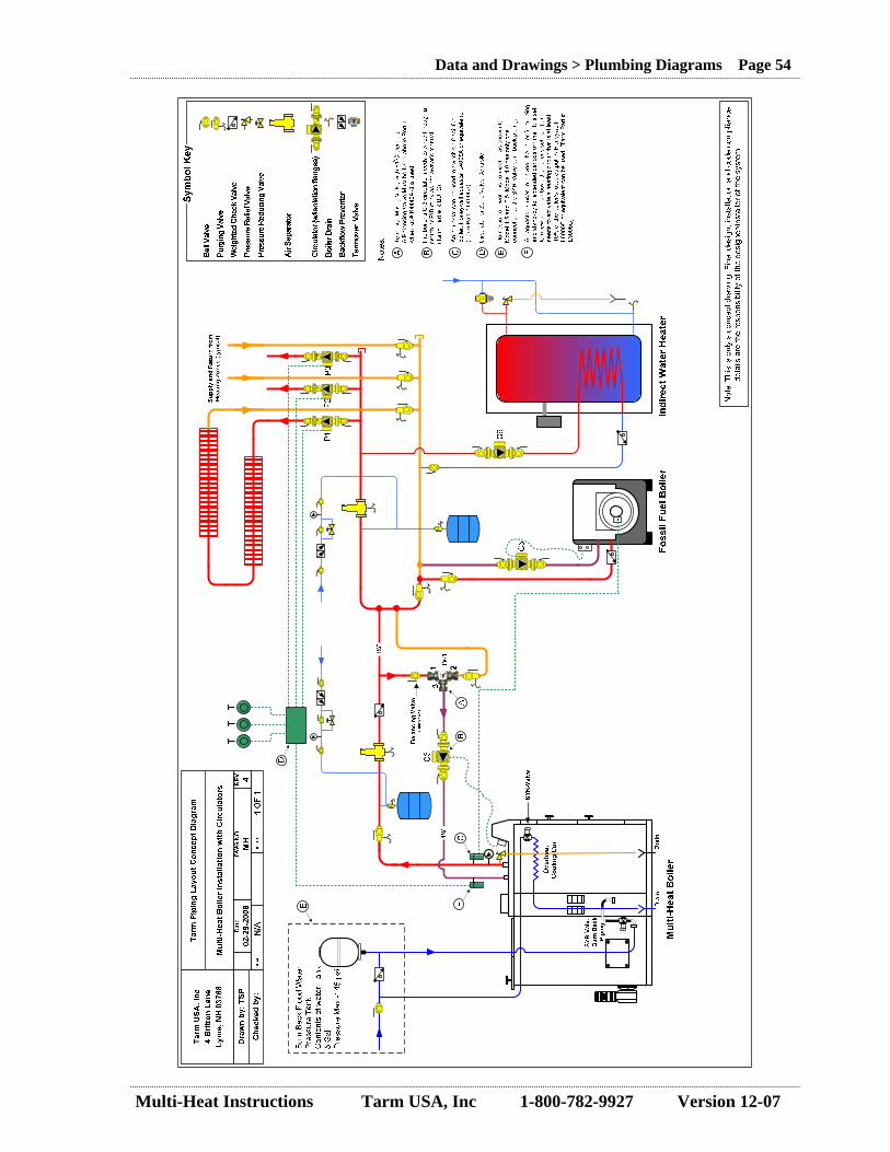
Multi-Heat Instructions Tarm USA, Inc 1-800-782-9927 Version 12-07
Data and Drawings > Plumbing Diagrams Page 54
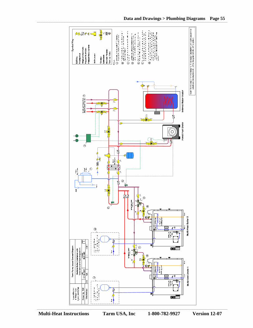
Multi-Heat Instructions Tarm USA, Inc 1-800-782-9927 Version 12-07
Data and Drawings > Plumbing Diagrams Page 55
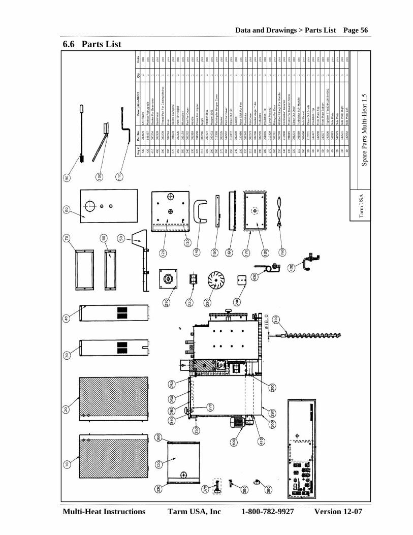
Multi-Heat Instructions Tarm USA, Inc 1-800-782-9927 Version 12-07
Data and Drawings > Parts List Page 56
Key
#
Part
No.
D
escr
iptio
n-M
H1.
5 Q
ty.
Uni
ts
430
0890
79
SY
R V
alve
1
pcs
420
1414
37
Pip
eset
Ret
rogr
ade
1 pc
s
410
0802
34
Gas
ket F
or G
earm
otor
1
pcs
400
0823
39
Gea
rmot
or
1 pc
s
390
0822
39
Thre
ad P
art F
or C
losi
ng M
echa
-1
pcs
380
0822
24
Kno
b 1
pcs
370
0916
23
Han
dle
Com
plet
e 1
pcs
360
0823
25
Par
t For
Hop
per
1 pc
s
350
0821
93
Mic
rosw
itch
1 pc
s
340
0822
62
Par
t For
Cov
er
1 pc
s
330
0823
18
Han
dle
1 pc
s
320
0915
60
Cov
er F
or H
oppe
r 1
pcs
310
0822
46
Aug
er
1 pc
s
300
0804
04
Hop
per 3
50L
1 pc
s
290
0804
02
Hop
per 2
00L
1 pc
s
280
0123
28
Pac
king
for H
oppe
r Cov
er
1 pc
s
270
0892
25
Gas
ket
1 pc
s
260
0425
62
Par
t For
Cov
er
1 pc
s
250
0123
37
Cle
an O
ut L
id
1 pc
s
240
0822
89
Gas
ket
1 pc
s
230
0208
56
Rot
or D
isk
For F
an
1 pc
s
220
0823
45
Fan
Mot
or
1 pc
s
210
0822
73
Fan
Cov
er
1 pc
s
200
0822
86
Gas
ket A
uger
Tub
e 1
pcs
190
0822
76
Turb
ulat
or
1 pc
s
180
0610
56
Insu
latio
n Ti
le
1 pc
s
170
0123
29
Cov
er P
acki
ng
1 pc
s
160
0822
81
Fitti
ngs
For D
oor
1 pc
s
150
0822
78
Wel
ded
Fitti
ngs
For H
andl
e 1
pcs
140
2189
40
Com
bust
ion
Cer
amic
1
pcs
130
0916
15
Fram
e Fo
r Iso
latio
n St
one
1 pc
s
120
0912
24
Cle
an O
ut D
oor
1 pc
s
110
0915
89
Turb
ulat
or S
pin
Han
dle
1 pc
s
100
0094
96
Ash
Sho
vel
1 pc
s
90
2102
01
Cle
an O
ut B
rush
1
pcs
80
0424
97
Insu
latio
n To
p 1
pcs
70
0425
80
Fron
t Pla
te T
op
1 pc
s
60
0425
77
Fron
t Pla
te B
otto
m
1 pc
s
50
0425
90
Top
Box
778
x508
x195
.5x4
0x2
1 pc
s
40
0425
83
Sid
e P
late
1
pcs
30
0425
79
Sid
e P
late
1
pcs
20
0425
81
Sid
e P
late
Rig
ht
1 pc
s
10
0425
82
Sid
e P
late
Lef
t 1
pcs
Tarm
USA
Sp
are
Parts
Mul
ti-H
eat 1
.5
6.6 Parts List

Multi-Heat Instructions Tarm USA, Inc 1-800-782-9927 Version 12-07
Data and Drawings > Parts List Page 57
Tarm
USA
Sp
are
Parts
Mul
ti-H
eat 2
.5
Key
#
Part
No.
D
escr
iptio
n-M
H2.
5 Q
ty.
Uni
ts
640
2191
52
Rep
air P
aint
Blu
e 1
pcs
630
2191
92
Rep
air P
aint
Blu
e. R
al 5
000
1 pc
s
620
0893
09
Cov
erin
g P
late
316
x92
1 pc
s
610
0893
08
Cov
erin
g P
late
483
x92x
37
1 pc
s
480
0891
00
Pla
stic
Cov
er 5
94x1
53x3
1
pcs
590
2102
04
Cle
an O
ut B
rush
110
x153
L=8
00
1 pc
s
580
0894
01
Cle
an O
ut S
hove
l 1
pcs
570
0924
96
Cle
anin
g B
rush
2½
" L=8
00
1 pc
s
560
0094
96
Ash
Sho
vel M
ulti-
Hea
t 1
pcs
550
0822
35
Fitti
ngs
For C
over
1
pcs
540
0822
60
Wel
ded
Fitti
ngs
For H
andl
e 1
pcs
530
0916
24
Fram
e Fo
r Iso
l. St
one
391x
290x
85
1 pc
s
520
0911
40
Cle
an O
ut D
oor M
ulti-
Hea
t 4.0
1
pcs
510
0890
87
Fram
e Fo
r Iso
l. St
one
468x
412x
16
1 pc
s
500
0890
88
Ash
/Firi
ng D
oor M
H 2
.5
1 pc
s
490
0890
98
Fitti
ngs
For D
oor L
=503
1
pcs
480
0890
98
Fitti
ngs
For H
andl
e 1
pcs
470
0114
56
Cov
er P
acki
ng M
ulti-
Hea
t 2.5
1.
700
M
460
0890
85
Insu
latio
n Ti
le A
sh D
oor
1 pc
s
450
0123
23
Cov
er P
acki
ng M
ulti-
Hea
t 4.0
1
pcs
440
0610
54
Insu
latio
n Ti
le A
sh D
oor
1 pc
s
430
0606
49
Pac
king
154
x110
x3
1 pc
s
420
0123
24
Cle
an O
ut L
id
1 pc
s
410
0606
43
Pac
king
170
x170
x6 H
eat R
esis
t. 1
pcs
400
0822
04
Fan
Cov
er
1 pc
s
390
0821
90
Fan
Mot
or E
B 95
C 2
8/2
1 pc
s
380
0890
94
Rot
or D
isk
For F
an
1 pc
s
370
0803
74
Hop
per 6
00L
1 pc
s
360
0802
58
Hop
per 3
60L
1 pc
s
350
0890
79
Ther
mal
Val
ve S
YR
1
pcs
340
0890
90
Pip
eSet
Ret
rogr
ade
Com
bust
ion
1 pc
s
330
0891
01
Gla
ss W
ool I
ns T
op 8
00x5
00x1
00
1 pc
s
320
0893
07
Top
Box
600
x802
MH
2.5
1
pcs
310
0893
03
Fron
t Pla
te M
iddl
e 59
6x12
6x34
1
pcs
300
0893
04
Fron
t Pla
te T
op 5
96x2
34x3
4 1
pcs
290
0891
04
Pac
king
Cer
amic
1
pcs
280
0823
35
Gea
rmot
or
1 pc
s
270
0892
25
Gas
ket
1 pc
s
260
0425
63
Par
t For
Cov
er 3
80x4
5x28
x3
1 pc
s
250
0425
62
Par
t For
Cov
er 3
80x4
5x28
x3
1 pc
s
240
0821
93
Mic
rosw
itch
1 pc
s
230
0911
41
Cov
ers
For H
oppe
r 1
pcs
220
0822
47
Par
t For
Hop
per
1 pc
s
210
0123
21
Pac
king
For
Hop
per C
over
360
/600
1
pcs
200
0822
97
Han
dle
1 pc
s
130
0821
92
Aug
er
1 pc
s
120
0822
62
Hop
per L
atch
1
pcs
110
0822
39
Thre
ad P
art F
or L
atch
1
pcs
100
0822
24
Han
dle
Kno
b 1
pcs
90
0916
23
Han
dle
Cpl
1
pcs
80
0905
10
Ret
arde
r 1
pcs
70
0890
96
Flue
Tile
1
pcs
60
0894
00
Com
bust
ion
Cer
amic
s 1
pcs
50
0894
02
Ash
pan
1 pc
s
40
0425
91
Sid
e P
late
1
pcs
30
0425
97
Sid
e P
late
1
pcs
20
0893
02
Sid
e P
late
Rig
ht
1 pc
s
10
0893
01
Sid
e P
late
Lef
t 1
pcs
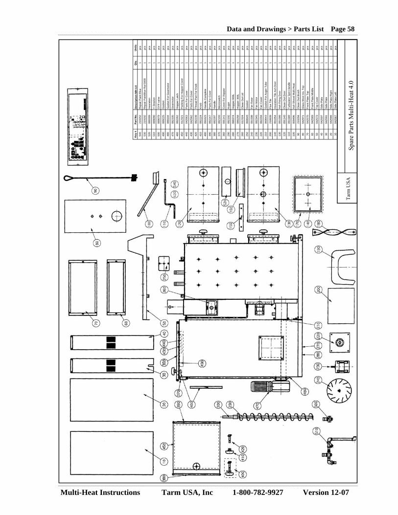
Multi-Heat Instructions Tarm USA, Inc 1-800-782-9927 Version 12-07
Data and Drawings > Parts List Page 58
Key
#
Part
No.
D
escr
iptio
n-M
H 4
.0
Qty
. U
nits
54
0 21
9152
R
epai
r Pai
nt B
lue
1 pc
s
530
2191
92
Rep
air P
aint
Blu
e R
al 5
000
1 pc
s
520
0893
09
Insu
latio
n 1
pcs
510
0890
90
Y-S
train
er
1 pc
s
500
0890
79
SY
R v
alve
1
pcs
490
0892
25
Gas
ket
1 pc
s
480
0891
04
Gas
ket F
or G
earm
otor
1
pcs
470
0823
35
Gea
rmot
or
1 pc
s
460
0822
62
Hop
per L
atch
1
pcs
450
0123
21
Pac
king
For
Hop
per C
over
1
pcs
440
0425
63
Par
ts F
or C
over
1
pcs
430
0425
62
Par
ts F
or C
over
1
pcs
420
0822
39
Thre
ad P
art F
or K
nob
1 pc
s
410
0822
24
Kno
b 1
pcs
400
0916
23
Han
dle
Com
plet
e 1
pcs
390
0822
47
Par
ts F
or C
over
1
pcs
380
0822
97
Han
dle
1 pc
s
370
0821
93
Mic
rosw
itch
1 pc
s
360
0911
41
Cov
er F
or H
oppe
r 1
pcs
290
0821
92
Aug
er
1 pc
s
280
0803
74
Hop
per 6
00L
1 pc
s
270
0802
58
Hop
per 3
60L
1 pc
s
260
0123
24
Cle
an O
ut L
id
1 pc
s
250
0606
49
Gas
ket
1 pc
s
240
0915
98
Fan
Rot
or
1 pc
s
230
0823
45
Fan
Mot
or
1 pc
s
220
0822
04
Fan
Cov
er
1 pc
s
210
0606
43
Gas
ket F
or A
uger
Tub
e 1
pcs
200
2189
39
Flue
Tile
1
pcs
140
0610
54
Insu
latio
n Ti
le A
sh D
oor
1 pc
s
130
0910
99
Ash
Firi
ng D
oor
1 pc
s
120
0911
40
Cle
an O
ut D
oor
1 pc
s
110
0915
89
Turb
ulat
or S
pin
Han
dle
1 pc
s
100
0094
96
Ash
Sho
vel M
ulti-
Hea
t 1
pcs
90
2102
04
Cle
an O
ut B
rush
1
pcs
80
0429
71
Gla
ss W
ool I
ns. T
op
1 pc
s
70
0425
70
Fron
t Pla
te T
op
1 pc
s
60
0425
69
Fron
t Pla
te M
iddl
e 1
pcs
50
0425
73
Top
Cov
er
1 pc
s
40
0425
97
Sid
e P
late
1
pcs
30
0425
91
Sid
e P
late
1
pcs
20
0425
66
Sid
e P
late
Rig
ht
1 pc
s
10
0425
67
Sid
e P
late
Lef
t 1
pcs
Tarm
USA
Sp
are
Parts
Mul
ti-H
eat 4
.0
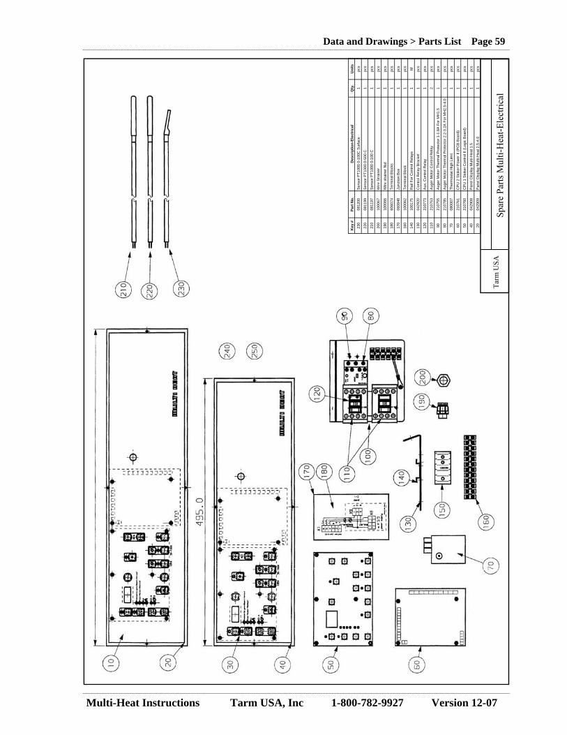
Multi-Heat Instructions Tarm USA, Inc 1-800-782-9927 Version 12-07
Data and Drawings > Parts List Page 59
Key
#
Part
No.
D
escr
iptio
n-El
ectr
ical
Q
ty.
Uni
ts
230
0812
00
Sen
sor P
T100
0 0-
100C
Sur
face
1
pcs
220
0811
99
Sen
sor P
T100
0 0-
500
C
1 pc
s
210
0811
97
Sen
sor P
T100
0 0-
100
C
1 pc
s
200
1000
67
Wire
Stra
iner
1
pcs
190
1000
66
Wire
stra
iner
Nut
1
pcs
180
6060
74
Term
inal
Blo
cks
1 pc
s
170
0608
48
Junc
tion
Box
1
pcs
160
1000
62
Term
inal
Blo
ck
1 pc
s
140
1001
75
Rai
l For
Con
trol R
elay
s 1
M
130
0429
20
Con
trol R
elay
Bra
cket
1
pcs
120
2107
73
Aux
. Con
trol R
elay
1
pcs
110
2107
53
Aug
er M
otor
Con
trol R
elay
2
pcs
90
2107
55
Aug
er M
otor
The
rmal
Pro
tect
or 1
-1.8
A F
or M
H1.
5 1
pcs
80
2107
85
Aug
er M
otor
The
rmal
Pro
tect
or 2
.2-3
.2A
For
MH
2.5-
4.0
1 pc
s
70
0800
07
Ther
mos
tat H
igh
Lim
it 1
pcs
60
2107
61
CP
U 2
Sto
ker P
ower
II (P
CB
Boa
rd)
1 pc
s
50
2107
60
CP
U 1
Sto
ker C
ontro
l II (
Logi
c B
oard
) 1
pcs
40
0429
08
Pan
el D
ispl
ay M
ulti-
Hea
t 1.5
1
pcs
20
0429
09
Pan
el D
ispl
ay M
ulti-
Hea
t 2.5
-4.0
1
pcs
Tarm
USA
Sp
are
Parts
Mul
ti-H
eat-E
lect
rical
Multi-Heat Instructions Tarm USA, Inc 1-800-782-9927 Version 12-07
Data and Drawings > Warranty Information Page 60
7.0 Warranty Information
MULTI-HEAT WARRANTY – FOR USE IN U.S.A. TARM USA INC. (Importer) warrants this residential steel boiler identified below and the motors and the electronic con-trols and the auger, and the refractory against defects in the material and workmanship under normal home use and service. TO THE ORIGINAL PURCHASER AT THE ORIGINAL INSTALLATION SITE in the United States and Canada under the following terms.
BOILER BODY LIMITED 5 YEAR WARRANTY
Subject to all the limitations stated below, Importer warrants the steel boiler body (but not including doors, refractory or other components) against defects in materials and workmanship resulting in breaks or leaks causing significant impairment of performance for a period of 5 years. IMPORTER’S OBLIGATION. The importer’s obligation under this limited warranty is to provide payment of the cost of repair of the warranted boiler, or at its option to replace the warranted boiler. IMPORTER will pay all required labor and the costs of all materials for the repair of the boiler defects arising during the five years of the warranty period. Shipping charges in connec-tion with replacement or repair shall be paid by the owner.
DOORS, REFRACTORY, AUGER, COOLING COIL LIMITED THREE YEAR WARRANTY
YEARS ONE THROUGH THREE: subject to all the limitations stated in the following table, Importer warrants the doors, refrac-tory, auger and the cooling coil against defects in materials and workmanship resulting in breaks or leaks causing significant impairment of performance.
Warranty Year
1 100% of parts and labor 2 100% of parts only 3 50% of parts only
OTHER COMPONENTS 1 YEAR WARRANTY
Motors, electronic controls, and all other components have a one year warranty.
CONDITIONS OF WARRANTY This limited warranty covers only repairs or replacements result-ing from defects in materials and workmanship. This warranty shall be void if the boiler is not installed by a quali-fied heating installer or is not installed, maintained, and operated as per the Instructions Manual. The boiler must be cleaned and maintained above the minimum temperature as specified.. This warranty shall be void if the owner fails to have the boiler serviced or inspected at least once every year by an experi-enced and qualified service person. EXCLUSIONS: Expressly excluded from coverage by this lim-ited warranty are the following: Ordinary wear and tear, repairs or replacements necessitated by normal use as described in the Instructions Manual. Repairs or replacements arising from the effects of corrosive water supply or corrosive by-products of combustion. Repairs or replacements of fittings, motors, or any or all controls, relief or regulating valves, transformers, and accessories. Repairs or replacements to repair damage caused by operation with inadequate draft, too hot or too cool operation, from cold start, or any other use in violation of the instructions or cautions set forth in the installation an operation Instructions Manual. The repair or replacement of any component furnished by any other supplier, or damage caused by the functioning or malfunc-tioning of any such component. PURCHASERS’ LEGAL RIGHTS: This warranty gives you specific legal rights, and you may also have other rights which may vary from state to state. This warranty shall not be con-strued as inconsistent with any federal, state or municipal law or any regulations promulgated in connection herewith. Questions regarding this warranty may be referred to TARM USA, INC 5 Main St., Lyme, NH 03768 U.S.A. Phone: 1-800-STAY-WARM HOW AND WHERE TO GET SERVICE Repairs or replacements under this limited warranty must be performed by your dealer or someone authorized by him. You may be required to present this limited warranty to the dealer before any work is performed. You must pay for any work performed which is not covered by this limited warranty or which is not authorized by the dealer.
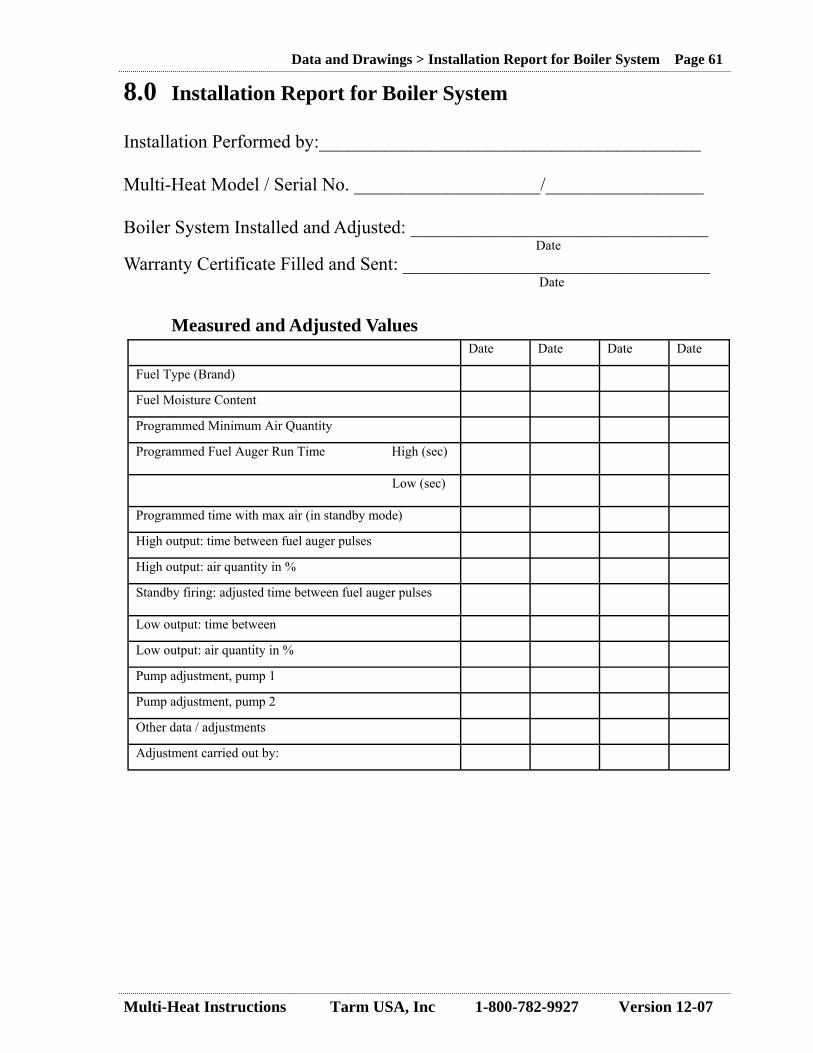
Multi-Heat Instructions Tarm USA, Inc 1-800-782-9927 Version 12-07
Data and Drawings > Installation Report for Boiler System Page 61
8.0 Installation Report for Boiler System Installation Performed by:_________________________________________ Multi-Heat Model / Serial No. ____________________/_________________ Boiler System Installed and Adjusted: ________________________________ Date Warranty Certificate Filled and Sent: _________________________________ Date Measured and Adjusted Values
Date Date Date Date
Fuel Type (Brand)
Fuel Moisture Content
Programmed Minimum Air Quantity
Programmed Fuel Auger Run Time High (sec)
Low (sec)
Programmed time with max air (in standby mode)
High output: time between fuel auger pulses
High output: air quantity in %
Standby firing: adjusted time between fuel auger pulses
Low output: time between
Low output: air quantity in %
Pump adjustment, pump 1
Pump adjustment, pump 2
Other data / adjustments
Adjustment carried out by:
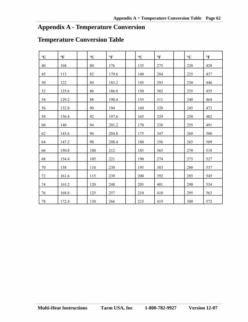
Multi-Heat Instructions Tarm USA, Inc 1-800-782-9927 Version 12-07
Appendix A > Temperature Conversion Table Page 62
Appendix A - Temperature Conversion Temperature Conversion Table
°C °F °C °F °C °F °C °F
40 104 80 176 135 275 220 428
45 113 82 179.6 140 284 225 437
50 122 84 183.2 145 293 230 446
52 125.6 86 186.8 150 302 235 455
54 129.2 88 190.4 155 311 240 464
56 132.8 90 194 160 320 245 473
58 136.4 92 197.6 165 329 250 482
60 140 94 201.2 170 338 255 491
62 143.6 96 204.8 175 347 260 500
64 147.2 98 208.4 180 356 265 509
66 150.8 100 212 185 365 270 518
68 154.4 105 221 190 274 275 527
70 158 110 230 195 383 280 537
72 161.6 115 239 200 392 285 545
74 165.2 120 248 205 401 290 554
76 168.8 125 257 210 410 295 563
78 172.4 130 266 215 419 300 572

Multi-Heat Instructions Tarm USA, Inc 1-800-782-9927 Version 12-07
Appendix B > Extra Control Panel Layout Page 63
Appendix B - Extra Control Panel Layout
E F G
H
A
B
C
R
P
K
L
M
ºC
Boi
ler
On
Whe
n L
it
Ala
rm O
n D
ispl
ay
If L
it Pu
sh T
o C
lear
Man
ually
A
dvan
ces
Fuel
Into
80
MEN
U
ALA
RM
ON
SEK
. SE
K.
MIN
.
REG
SET J
Man
ually
Pu
lls
Fuel
Out
Dis
play
ing
Tem
pera
ture
of
Wat
er L
eavi
ng B
oile
r
Dis
play
ing
Tem
pera
ture
of
Wat
er R
etur
ning
To
Boi
ler
Dis
play
ing
Boi
ler
Wat
er
Dis
play
ing
Flue
Gas
Not
Use
d
Not
Use
d
Cir
cula
tor
Pum
p O
n W
hen
Lit
Use
d w
ith “
R”
To
Adj
ust
Boi
ler
Se
t Poi
nt
Ope
ratin
g A
t Hig
h W
hen
Lit
Ope
ratin
g A
t Lo
Whe
n L
it
Ope
ratin
g O
n St
and
By
Whe
n L
it
Man
ual
Whe
n L
it
A
uto
(2 S
tep)
I
100%
30
-100
%
UP Dow
n
Adj
ust
Mod
e
Push
To
Cyc
le
Thr
u T
emps
M
onito
red
At
Lef
t D
Cut
Her
e
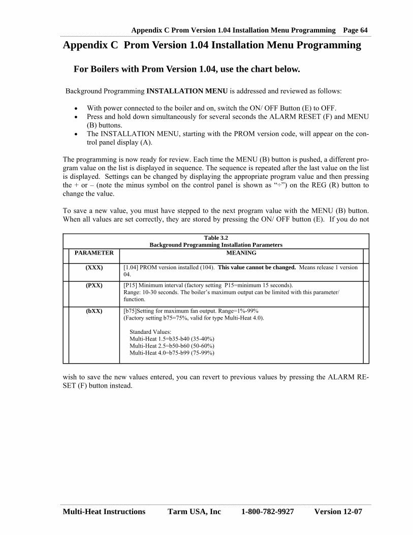
Multi-Heat Instructions Tarm USA, Inc 1-800-782-9927 Version 12-07
Appendix C Prom Version 1.04 Installation Menu Programming Page 64
Appendix C Prom Version 1.04 Installation Menu Programming For Boilers with Prom Version 1.04, use the chart below. Background Programming INSTALLATION MENU is addressed and reviewed as follows:
• With power connected to the boiler and on, switch the ON/ OFF Button (E) to OFF. • Press and hold down simultaneously for several seconds the ALARM RESET (F) and MENU
(B) buttons. • The INSTALLATION MENU, starting with the PROM version code, will appear on the con-
trol panel display (A). The programming is now ready for review. Each time the MENU (B) button is pushed, a different pro-gram value on the list is displayed in sequence. The sequence is repeated after the last value on the list is displayed. Settings can be changed by displaying the appropriate program value and then pressing the + or – (note the minus symbol on the control panel is shown as “÷”) on the REG (R) button to change the value. To save a new value, you must have stepped to the next program value with the MENU (B) button. When all values are set correctly, they are stored by pressing the ON/ OFF button (E). If you do not
wish to save the new values entered, you can revert to previous values by pressing the ALARM RE-SET (F) button instead.
Table 3.2 Background Programming Installation Parameters
PARAMETER MEANING
(XXX) [1.04] PROM version installed (104). This value cannot be changed. Means release 1 version 04.
(PXX) [P15] Minimum interval (factory setting P15=minimum 15 seconds). Range: 10-30 seconds. The boiler’s maximum output can be limited with this parameter/function.
(bXX) [b75]Setting for maximum fan output. Range=1%-99% (Factory setting b75=75%, valid for type Multi-Heat 4.0).
Standard Values: Multi-Heat 1.5=b35-b40 (35-40%) Multi-Heat 2.5=b50-b60 (50-60%) Multi-Heat 4.0=b75-b99 (75-99%)

Multi-Heat Instructions Tarm USA, Inc 1-800-782-9927 Version 12-07
Appendix C > Termovar Information Sheet Page 65
Appendix D - Termovar Information Sheet
TERMOVAR 4340A-3 TEMPERING VALVE
The TERMOVAR TEMPERING VALVE is an automatic thermally operated tempering valve for solid-fuel boiler installations with or without a storage tank. The TERMOVAR ensures a minimum return water temperature to the heating boiler, which increases combustion efficiency, prevents tar-ring and considerably prolongs the lifetime for the solid-fuel boiler. The TERMOVAR eliminates the risk of destructive thermal shock to both steel and cast iron boilers. The TERMOVAR thermally operated tempering valves render a more effective burning and are therefore a necessary part of a solid-fuel boiler installation. Installation and Function
The thermostatic element in the TERMOVAR prevents return of cold return water to the boiler until the boiler reaches operating temperature. The TERMOVAR then gradually opens, blend-ing hot boiler supply water with the cold return water. Once system temperature equalizes, the TERMOVAR opens fully to allow full flow to and from the heating load (the house and/or a heat storage system). The TERMOVAR valve is to be mounted between the boiler and the heat load in the return pipe, as shown in the diagram below. A circulator (designated C-3) must be installed between the TERMOVAR valve and the boiler. This circulator should be controlled by an aquastat that measures boiler water temperature or, when there is a heat storage tank being used, by a sensor that measures smoke box temperature.
Supply (To Heat Load) Return (From Heat Load)
Balancing Valve (Start with this valve closed halfway, i.e., at 45 degrees.)
Termovar C-3

Multi-Heat Instructions Tarm USA, Inc 1-800-782-9927 Version 12-07
Appendix > Notes Page 66
Notes: