Embed Size (px)
Citation preview
MTC HC-3000 INSTALLATION, OPERATING, AND
MAINTENANCE MANUALHigh Capacity Mobile Tank Cleaning,
Fuel Optimization, and Transfer System
AXI.International AXInternational AXIFuel AXIFuel
1.239.690.9589 1.877.425.4239 Toll Free www.AXI-International.com REV0303HC300010318
1.239.690.9589AXI.International AXInternational AXIFuel AXIFuel1.800.425.4239 Toll Free
www.AXI-International.com
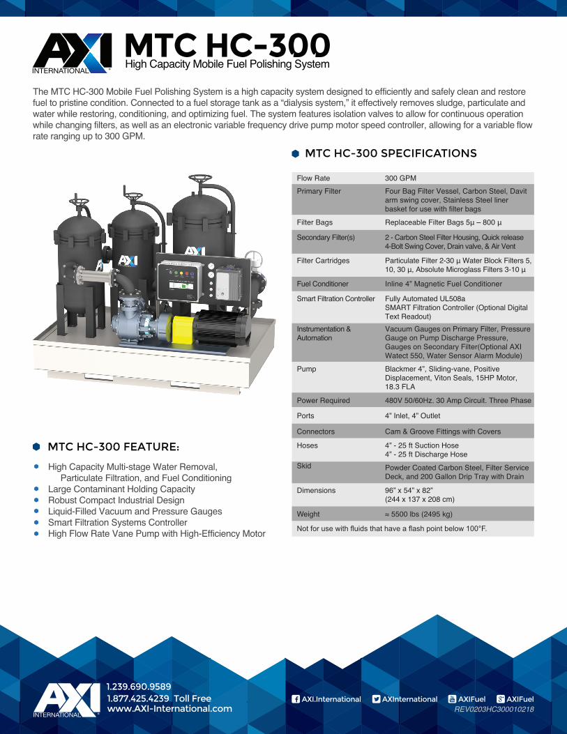
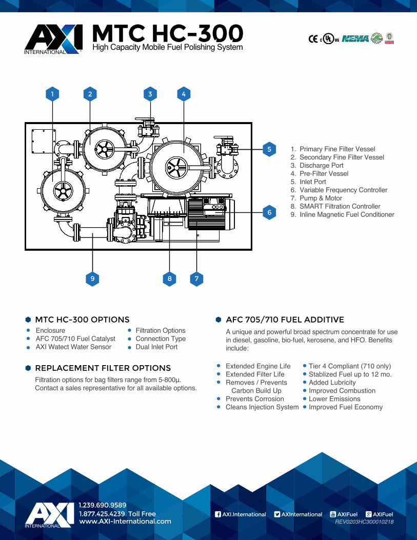
MTC HC-300High Capacity Mobile Fuel Polishing System
The MTC HC-300 Mobile Fuel Polishing System is a high capacity system designed to efficiently and safely clean and restore fuel to pristine condition. Connected to a fuel storage tank as a “dialysis system,” it effectively removes sludge, particulate and water while restoring, conditioning, and optimizing fuel. The system features isolation valves to allow for continuous operation while changing filters, as well as an electronic variable frequency drive pump motor speed controller, allowing for a variable flow rate ranging up to 300 GPM.
MTC HC-300 SPECIFICATIONS
1.239.690.9589AXI.International AXInternational AXIFuel AXIFuel1.877.425.4239 Toll Free
www.AXI-International.com
Flow Rate 300 GPMPrimary Filter Four Bag Filter Vessel, Carbon Steel, Davit
arm swing cover, Stainless Steel liner basket for use with filter bags
Filter Bags
Replaceable Filter Bags 5μ – 800 μ
Secondary Filter(s) 2 - Carbon Steel Filter Housing, Quick release 4-Bolt Swing Cover, Drain valve, & Air Vent
Filter Cartridges Particulate Filter 2-30 μ Water Block Filters 5, 10, 30 μ, Absolute Microglass Filters 3-10 μ
Fuel Conditioner Inline 4” Magnetic Fuel Conditioner
Smart Filtration Controller Fully Automated UL508a SMART Filtration Controller (Optional DigitalText Readout)
Instrumentation &Automation
Vacuum Gauges on Primary Filter, PressureGauge on Pump Discharge Pressure,Gauges on Secondary Filter(Optional AXI Watect 550, Water Sensor Alarm Module)
Dimensions 96” x 54” x 82”
Ports 4” Inlet, 4” Outlet
Connectors Cam & Groove Fittings with Covers
Hoses 4” - 25 ft Suction Hose4” - 25 ft Discharge Hose
Skid Powder Coated Carbon Steel, Filter ServiceDeck, and 200 Gallon Drip Tray with Drain
Power Required 480V 50/60Hz. 30 Amp Circuit. Three Phase
Pump Blackmer 4”, Sliding-vane, PositiveDisplacement, Viton Seals, 15HP Motor,18.3 FLA
(244 x 137 x 208 cm)
Weight ≈ 5500 lbs (2495 kg)
MTC HC-300 FEATURE:
High Capacity Multi-stage Water Removal, Particulate Filtration, and Fuel ConditioningLarge Contaminant Holding CapacityRobust Compact Industrial DesignLiquid-Filled Vacuum and Pressure GaugesSmart Filtration Systems ControllerHigh Flow Rate Vane Pump with High-Efficiency Motor
REV0203HC300010218
1.239.690.9589AXI.International AXInternational AXIFuel AXIFuel1.800.425.4239 Toll Free
www.AXI-International.com
A unique and powerful broad spectrum concentrate for usein diesel, gasoline, bio-fuel, kerosene, and HFO. Benefitsinclude:
EnclosureAFC 705/710 Fuel CatalystAXI Watect Water Sensor
Filtration OptionsConnection TypeDual Inlet Port
MTC HC-300 OPTIONS
REPLACEMENT FILTER OPTIONS
AFC 705/710 FUEL ADDITIVE
Tier 4 Compliant (710 only)Stablized Fuel up to 12 mo.Added LubricityImproved CombustionLower EmissionsImproved Fuel Economy
Extended Engine LifeExtended Filter LifeRemoves / Prevents Carbon Build UpPrevents CorrosionCleans Injection System
MTC HC-300High Capacity Mobile Fuel Polishing System
1.239.690.9589AXI.International AXInternational AXIFuel AXIFuel1.877.425.4239 Toll Free
www.AXI-International.com
Primary Fine Filter VesselSecondary Fine Filter VesselDischarge PortPre-Filter VesselInlet PortVariable Frequency ControllerPump & MotorSMART Filtration ControllerInline Magnetic Fuel Conditioner
1.2.3.4.5.6.7.8.9.
8 79
4321
5
6
Filtration options for bag filters range from 5-800μ.Contact a sales representative for all available options.
REV0203HC300010218
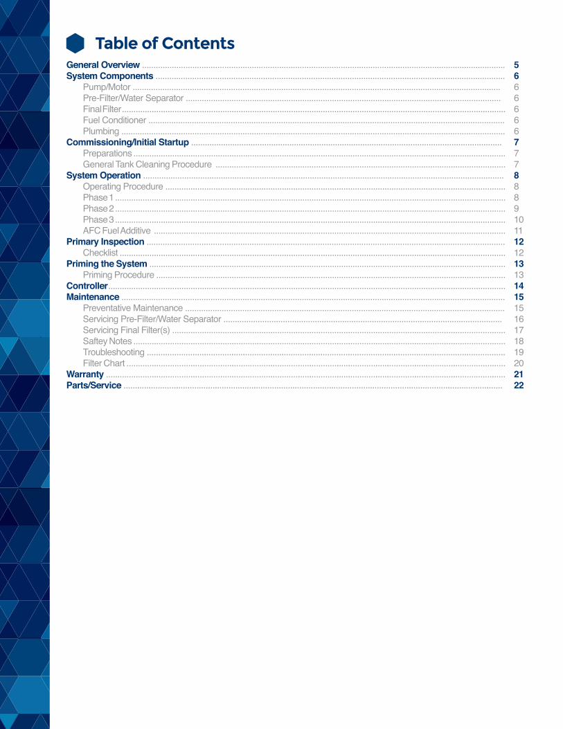
Table of ContentsGeneral Overview ...............................................................................................................................................................System Components .........................................................................................................................................................
Pump/Motor .................................................................................................................................................................Pre-Filter/Water Separator ..........................................................................................................................................Final Filter ........................................................................................................................................................................Fuel Conditioner ............................................................................................................................................................Plumbing ........................................................................................................................................................................
Commissioning/Initial Startup ........................................................................................................................................Preparations ...................................................................................................................................................................General Tank Cleaning Procedure ...............................................................................................................................
System Operation ..............................................................................................................................................................Operating Procedure .....................................................................................................................................................Phase 1 ...........................................................................................................................................................................Phase 2 ...........................................................................................................................................................................Phase 3 ...........................................................................................................................................................................AFC Fuel Additive ..........................................................................................................................................................
Primary Inspection .............................................................................................................................................................Checklist .........................................................................................................................................................................
Priming the System ............................................................................................................................................................Priming Procedure .........................................................................................................................................................
Controller ..............................................................................................................................................................................Maintenance ........................................................................................................................................................................
Preventative Maintenance ............................................................................................................................................Servicing Pre-Filter/Water Separator ..........................................................................................................................Servicing Final Filter(s) ..................................................................................................................................................Saftey Notes ...................................................................................................................................................................Troubleshooting .............................................................................................................................................................Filter Chart ......................................................................................................................................................................
Warranty ...............................................................................................................................................................................Parts/Service ......................................................................................................................................................................
5666666777888910111212131314151516171819202122
5
OV
ER
VIE
WS
YS
TE
M C
OM
PO
NE
NT
SP
RIM
AR
Y IN
SP
EC
TIO
NO
PE
RA
TIO
NP
RIM
ING
CO
NT
RO
LLE
RC
OM
MIS
SIO
NIN
GM
AIN
TE
NA
NC
E
REV0303HC300010318
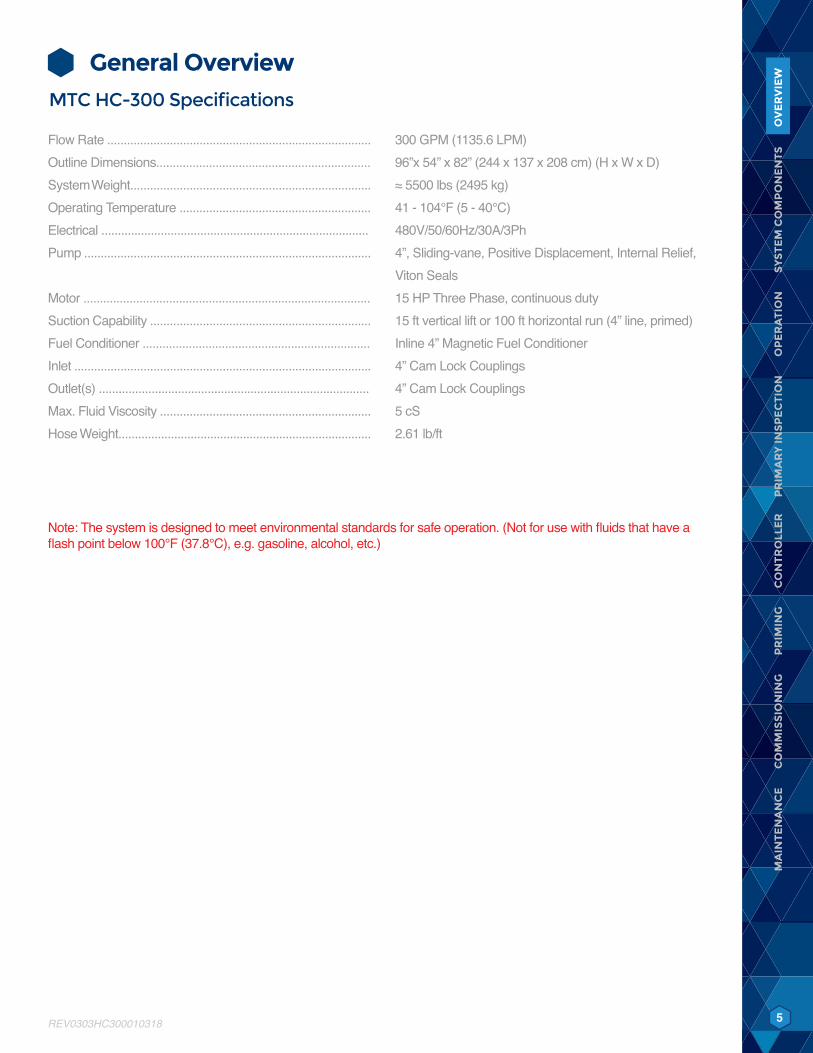
General OverviewMTC HC-300 Specifications
Note: The system is designed to meet environmental standards for safe operation. (Not for use with fluids that have a flash point below 100°F (37.8°C), e.g. gasoline, alcohol, etc.)
Flow Rate ................................................................................Outline Dimensions.................................................................System Weight.........................................................................Operating Temperature ..........................................................Electrical .................................................................................Pump .......................................................................................
Motor .......................................................................................Suction Capability ...................................................................Fuel Conditioner .....................................................................Inlet ..........................................................................................Outlet(s) ..................................................................................Max. Fluid Viscosity ................................................................Hose Weight.............................................................................
300 GPM (1135.6 LPM)96”x 54” x 82” (244 x 137 x 208 cm) (H x W x D)≈ 5500 lbs (2495 kg)41 - 104°F (5 - 40°C)480V/50/60Hz/30A/3Ph4”, Sliding-vane, Positive Displacement, Internal Relief, Viton Seals15 HP Three Phase, continuous duty15 ft vertical lift or 100 ft horizontal run (4” line, primed)Inline 4” Magnetic Fuel Conditioner4” Cam Lock Couplings4” Cam Lock Couplings5 cS2.61 lb/ft
OV
ER
VIE
W

6
SY
ST
EM
CO
MP
ON
EN
TS
PR
IMA
RY
INS
PE
CT
ION
OP
ER
AT
ION
PR
IMIN
GC
ON
TR
OLL
ER
CO
MM
ISS
ION
ING
MA
INT
EN
AN
CE
REV0303HC300010318
OV
ER
VIE
W
System Components
Control and Safety Devices• AXI International “Smart Filtration Controller” in electrical sub enclosure – UL 508A listed Industrial Control Panel• Pump control switch (Off/Manual), weatherproof, key operated• Alarm Reset --‐ weatherproof push button• Power available indicator• Pump running indicator• Inlet and outlet shut off butterfly valves• Internal pressure relieve valve• Primary filter high vacuum alarm indicator and system shutdown (vacuum sensors)• Secondary filter(s) high differential pressure alarm indicator and system shutdown (pressure sensors)• Pump motor starter with three--pole circuit breaker and contactor• High system pressure• High system vacuum
Pump/Motor• Positive displacement sliding vane pump• Internal relief valve• TEFC (Totally Enclosed Fan Cooled)
Pre-Filter/Water Separator• Single, multi-round bag filter vessels (#2 standard bag size)• Drain valve on the bottom• Differential vacuum gauge for vessel
Final Filter• Dual final filtration vessels (available with water block or particulate cartridge filters)• Differential pressure gauge for each vessel• Pressure switch for each vessel
Fuel Conditioner• Inline Magnetic Fuel Conditioner eliminates and prevents the formation of sediments that naturally occur in diesel fuel
and bio-blends
Carbon Steel Plumbing
SY
ST
EM
CO
MP
ON
EN
TS
7
SY
ST
EM
CO
MP
ON
EN
TS
PR
IMA
RY
INS
PE
CT
ION
OP
ER
AT
ION
PR
IMIN
GC
ON
TR
OLL
ER
MA
INT
EN
AN
CE
REV0303HC300010318
CO
MM
ISS
ION
ING
OV
ER
VIE
W
Commissioning/Initial Start-Up
PreparationsBefore operating the MTC, we recommend determining the amount of contaminants, free water, and sludge in the tank.
AXI International provides a variety of tank sampling equipment, including Sampling Pumps, tubing and bottles, as well as Tank Samplers (“Bacon Bomb”) – please see our FS Fluid Sampling line of products. Please make sure the samples are taken from the bottom of the tank (in the deepest spot). Use a stick with “Kolor Kut” paste on the end, reach through the top of the tank, and place the end of the stick all the way at the bottom of the tank. Kolor Kut paste will show the water level in the tank, and indicate how much water, and sludge, will have to be removed. Call AXI International for further information on other fuel sampling equipment.
General Tank Cleaning Procedure
In Fine Filtration Mode, the MTC system is continuously restoring, reconditioning, and returning the fuel back to the tank. Fine Filtration mode will continuously remove particles as small as 1 micron, utilizing high efficiency spin-on filters.
We always recommend keeping a “before” and “after” bottom tank sample for “show & tell” purposes to demonstrate the improvement of fuel color, clarity, and opacity.
8
SY
ST
EM
CO
MP
ON
EN
TS
PR
IMA
RY
INS
PE
CT
ION
OP
ER
AT
ION
PR
IMIN
GC
ON
TR
OLL
ER
CO
MM
ISS
ION
ING
MA
INT
EN
AN
CE
REV0303HC300010318
OV
ER
VIE
WO
PE
RA
TIO
N
System OperationOperating ProcedureHoses: The intake/suction hose is a reinforced vacuum hose. The return hose is black or blue/black, non-marking, high quality, discharge fuel hose. Both hoses are equipped with quick disconnects or Cam & Groove couplings.1. Attach quick disconnect end of suction hose to the quick disconnect Pre-Filter Inlet Port of the MTC.2. We highly recommend attaching a “stinger” or pipe (cut at an angle at the end that goes into the tank and is at minimum
the same inner diameter as the suction hose) to the suction hose to reach the lowest part of the tank bottom.3. Attach quick disconnect end of blue/black discharge hose to quick disconnect Pump Skid Discharge Port (before fine
filters) of the MTC.4. Place the end of the discharge hose in an appropriate-size container (Phase One only). Try to not agitate the fuel in the
tank and stir up and disperse water and sediment throughout the fuel –this will make it more difficult to remove later on.5. For Phases Two and Three, place the end of the discharge hose back in the tank as far away as possible from the
suction hose. Ensure that the hose is secured and will not vibrate out of the container when the system is operating.6. Verify that drain valves are closed and the system is set up in a stable and safe position.
Note: Never restrict the flow on the suction side of an MTC; e.g. by using a smaller ID hose or pipe or attaching the suction hose to a fitting on the tank that has a smaller ID than the hose. This will lead to excessive pump load, noise and ultimately damage the pump.
AXI recommends 3 phases to successfully polish a fuel tank: • 1. Bulk water and sludge removal• 2. Pre-filtration• 3. Final fuel polishingThis will ensure all water is removed from the fuel, particulate is removed, and the fuel is in an optimal condition. The goal of Phase One is to remove any free water and sludge on the bottom of the tank without mixing the water into an emulsified state within the fuel. Start the pump motor and be ready to immediately stop it. The vane pump will start pumping as long as the system is primed and the suction lift is not excessive. The flow of fuel can be observed in the suction hose. Watch for a steady flow of fuel into the container. Connect the Discharge Hose to the Pump Skid Discharge Port (before fine filters). It is also recommended to install a small ball valve on the suction “stinger” to break the vacuum for draining.
Phase 1: 1. Connect a “stinger” to the tank end of the suction hose. The stinger is obtained locally and fashioned according to the
requirements of the particular job. In general, the “stinger” is a piece of PVC pipe cut at an angle to facilitate removal of water and contaminants, when the “snorkel” is inserted into the fuel tank.
Note: Avoid restricting the flow on the suction side of the system. If it is necessary to use a smaller ID suction hose, a smaller ID “stinger”, or if the length of the suction hose is increased, reduce pump speed with the Speed Control Dial so that the vacuum gauge remains in the green color band. The system’s PLC controller will halt system operation automatically if the suction vacuum exceeds safe limits.
Note: To adjust vacuum settings of MTC HC-300, please contact AXI International.
9
SY
ST
EM
CO
MP
ON
EN
TS
PR
IMA
RY
INS
PE
CT
ION
OP
ER
AT
ION
PR
IMIN
GC
ON
TR
OLL
ER
CO
MM
ISS
ION
ING
MA
INT
EN
AN
CE
REV0303HC300010318
OP
ER
AT
ION
OV
ER
VIE
W
2. Connect the Suction hose to the System Inlet Port.3. Connect the Discharge Hose to the System Discharge Port4. Check all connections for integrity.5. Install a large micron (200µ or larger) bag filter in the Bag Filter Vessel and close vessel securely.6. Ensure no fine filters are in either of the last two filter vessels.7. Open the Inlet Ball Valve.8. Open the Discharge Ball Valve.9. Insert suction “stinger” into the tank and secure.10. Insert discharge hose into separate container for disposal (removal of unwanted contaminants).11. Verify that the “MANUAL/OFF” switch is in the “OFF” position.12. Connect the system to an appropriate power source.13. Verify that the Variable Frequency Controller dial is set at 20-30, so that the pump motor will start at lower intial speed.14. Switch the Smart Filtration Controller circuit breakers to on - the “System Power” light illuminates.15. Switch the Smart Filtration Controller to “MANUAL” to begin pumping.16. If the pump does not start, toggle the Variable Frequency Controller Lever switch to “Start”. This will be necessary for
the first cycle after the Smart Filtration Controller circuit breakers are switched on.17. Observe System Priming.18. Check for leaks or other abnormalities.19. If anything deviates contact AXI International immediately
Phase 2: After removing the bulk of the sludge and water from the tank into a separate container for disposal, the return hose is now inserted into the tank, ending Phase One. The goal of Phase Two is to remove any additional free water within the tank and also remove any large contaminants and sludge. This phase will clean the fuel and should be a precursor to using the more expensive fine filters (which are higher efficiency and cost). It should be noted that meeting required cleanliness codes is typically not possible with pre-filtering alone. Phase Two is used to extend the life of the fine filters, and remove the worst of the contaminants, before polishing with fine filters to meet the required cleanliness.1. Insert blue/black discharge hose into tank as far away from the suction hose as possible. In some cases, it is
recommended to remove the sending unit cover to gain sufficient access to the tank. In some cases, both hoses will have to be inserted through the same tank fill opening.
2. After verifying that both hoses are properly placed in the fuel tank and that the valves on the MTC system are in the correct position, switch on the pump and ensure proper fuel flow.
Depending on the amount of contaminant in the tank, we recommend you stop the pump shortly after priming and check for free water and sludge by draining the water from the bottom of the pre-filter.
Check the sump of the pre-filter periodically for build-up of free water.
3. The MTC should be kept running in the Phase Two recirculating mode until clean fuel samples can be drained from the pre-filter. Then, switch off the pump for final polishing.
10
SY
ST
EM
CO
MP
ON
EN
TS
PR
IMA
RY
INS
PE
CT
ION
PR
IMIN
GC
ON
TR
OLL
ER
CO
MM
ISS
ION
ING
MA
INT
EN
AN
CE
REV0303HC300010318
OV
ER
VIE
WO
PE
RA
TIO
N
Phase 3: Phase Three is the most important phase in meeting specific cleanliness codes. Unlike the pre-filter, the fine filters typically use absolute rated media. Absolute filters have a very high efficiency and will ensure that fuel leaving the system is clean to specification and has a low water content. Like previously mentioned, pre-filtering should be performed to remove any large particulate, water, and sludge. Pre-filtering will extend the life of the fine filters.1. Connect the Discharge Hose to the Discharge Port (after fine filters).2. Ensure catridge filters are in the first and/or second stage of final filter vessels.3. Increase pump motor speed as appropriate to continue fuel polishing and fuel restoration process.4. Limit motor overspeed operations to light load conditions. Motor over speed is when the speed indicator window
indicates greater than the nominal 60 Hz. 60 Hz is the normal “rated RPM speed” of the motor. At 60 Hz, (displayed in the Speed Indicator Window) Flow Rate will be approximately 300 GPM (attainable with new/lightly loaded filters).
5. Monitor process and change bag filters and filter elements as necessary.6. Bag filter vessel is equipped with a vacuum gauges. Final filter vessels have pressure gauges to show the pressure
condition of the pump. Differential gauges are installed to show the pressure drop over each filter individually.7. Now is the time to add AXI International AFC-710 Fuel Catalyst in a dose of 1 : 2500 or 1 gal of AFC-710 for 2500 gallons
of fuel. Higher doses of AFC-710 may be necessary depending on condition of fuel.
Note: System can run with fine filters in one, two, or none of the final filter vessels. This allows for phasing of the fuel cleaning process
Note: Pre-filter should always have some type of pre-filter bad in place during operation to extend life of the pump vanes.
11
SY
ST
EM
CO
MP
ON
EN
TS
CO
NT
RO
LLE
RC
OM
MIS
SIO
NIN
GM
AIN
TE
NA
NC
E
REV0303HC300010318
OP
ER
AT
ION
PR
IMIN
GO
VE
RV
IEW
AFC Fuel AdditiveThe use of AXI International AFC-705/710 Fuel Additive is an essential part of any tank cleaning and fuel polishing procedure, as AFC can more rapidly and efficiently decontaminate and clean the entire fuel system. The additive is best introduced into the process after Fine Filtration Mode. Before dosing the tank with AFC-705/710, remove as much of the sludge and free water as possible. Adding AFC-705/710 to the tank will speed up the cleaning process by breaking down and dissolving the sludge covering the tank walls and bottom.
AFC-705/710 will decontaminate areas and sections of the tank that are out of reach of the suction hose. It is recommended to use a higher concentration of one to twenty five hundred (1:2500) instead of one to five thousand (1:5000) for the first treatment. This has proven to be very helpful in accelerating the rate of dissolving sludge. Higher doses may be necessary, depending on contamination level of the fuel. AFC-705/710 is a full spectrum fuel additive, containing a combustion catalyst, surfactant (705), detergent, dispersant, corrosion inhibitor, lubricity enhancers, and a fuel stabilizer that eliminates the need for expensive, toxic biocides.
*Note: AFC-705 contains a surfactant. Surfactants can emulsify water into the fuel and damage HPCR injection systems. Consult AXI for recommendations on fuel treatment.
After Fuel Polishing Process1. Stabilize the FuelAFC-705/710 will stabilize the fuel in tanks used for long-term fuel storage. When a recirculation or STS Automatic Filtration System is not in place, AFC-705/710 will maintain fuel quality and prevent formation of sludge for up to twelve months. Added after the fuel polishing process, it is not necessary to add more AFC-705/710 until additional fuel is added into the tank, or an environmental condition for the fuel has been altered (introduction of water or other contamination)2. Prevent Water from AccumulatingThe use of AXI Water Eliminators, or tank breathers, will prevent water from accumulating in the tank. The water eliminators will absorb and remove any water from condensation or other sources. Preventing water accumulation eliminates microbial growth and the need for toxic biocides.3. Monitor Fuel QualityLiquid-Cult Fuel Test Kits are ideal for monitoring your fuel supply for microbial contamination. The tests provide indication of bacterial and fungal activity.4. Intelligent Fuel Management SolutionsAXI International Intelligent Fuel Management Solutions significantly lower operating costs, save fuel, eliminate periodic tank cleaning and the build up of solids, sludge, and acids. AXI International Technology enhances personnel safety and addresses environmental concerns by preventing the need for costly toxic biocides. Larger capacity Mobile and Stationary Tank Cleaning Systems are available.
! IMPORTANT ! It is recommended that only qualified, experienced personnel, familiar with this equipment, who have read and understood all the instructions in this manual should operate and maintain the system.
! WARNING ! Do not use with gasoline, solvents, corrosive liquids, food liquids or other liquids having a flash point less than 100°F. Use with gasoline or use with any flammable liquids at a temperature exceeding their flash point, presents an immediate explosion and fire hazard
PR
IMA
RY
INS
PE
CT
ION
12
SY
ST
EM
CO
MP
ON
EN
TS
OP
ER
AT
ION
CO
MM
ISS
ION
ING
MA
INT
EN
AN
CE
REV0303HC300010318
PR
IMA
RY
INS
PE
CT
ION
CO
NT
RO
LLE
RO
VE
RV
IEW
PR
IMIN
G
Primary Inspection
Upon arrival, the system and accessories must be visually inspected before installation. Improper handling during shipping may cause physical or electrical problems. Immediately report or note any damages (also concealed ones) to the shipper.
Checklist ❑ If the packing crate shows signs of damage inspect the system for damage. ❑ Check the entire system for damage that could indicate mechanical or electrical problems. ❑ Check pump/motor hardware and all plumbing connections for tightness. ❑ Check all electrical terminals and connections for tightness.
13
SY
ST
EM
CO
MP
ON
EN
TS
PR
IMA
RY
INS
PE
CT
ION
OP
ER
AT
ION
CO
NT
RO
LLE
RC
OM
MIS
SIO
NIN
GM
AIN
TE
NA
NC
E
REV0303HC300010318
PR
IMIN
GO
VE
RV
IEW
Priming the System
Note: The system is equipped with a positive displacement vane pump. It should never be run dry and started without the hoses attached and/or valves in the closed position. Failure to do so may damage the bypass valve and/or pump.
Priming ProcedureBefore turning on the pump make sure the entire suction side of the MTC system (suction hose, separator, plumbing, pump, strainer …) is primed and filled with oil/diesel fuel. Running the pump dry could cause pump damage and pump to not operate properly.
Note: The separator/coalescer has to be full at all time to perform properly.
14
SY
ST
EM
CO
MP
ON
EN
TS
PR
IMA
RY
INS
PE
CT
ION
OP
ER
AT
ION
PR
IMIN
GC
OM
MIS
SIO
NIN
GM
AIN
TE
NA
NC
E
REV0303HC300010318
CO
NT
RO
LLE
RO
VE
RV
IEW
Controller
Manual/OffManual- Normal pump/system on/off control.
Note: Unsupervised operation of the system is not recommended or supported by AXI International. The system requires full-time technician monitoring whenever in operation. Please call AXI with any questions.
Circuit Breakers3 Phase: 30 Ampere 3-gang breaker for Variable Frequency Controller and pump motor (Left gang), 3 Phase 10 Ampere 3-gang breaker for electronics (Right gang).
Variable Frequency ControllerIn normal operation the Variable Frequency Controller is used ONLY to change the speed of the pump. When the Smart Filtration Controller is switched to “Manual” the pump will turn on and accelerate to the VFD speed.
Speed Indicator WindowThe number shown on the Variable Frequency Controller display is the frequency of the current that is being sent to the pump motor. 60 Hz for example is the rated speed of the motor. If the Variable Frequency Controller display indicates 30, this means that the pump is turning at ½ of the rated speed.
Speed Controller UP and DOWN ArrowsChanges pump speed from 10 Hz to 60 Hz.
Note: ALL other Speed Controller Control Pad Functions (Run, Stop, Forward, Reverse) are disabled.
AlarmsThe system is equipped with an AXI International Smart Filtration Controller. System and alarm status are displayed on the industrial control panel (on the door) via indicator lights, and LCD screen on PLC inside.
Alarms featured on the system include:• Leak Detection• Primary filter high vacuum alarm indicator and system shutdown (vacuum sensor)• Secondary filter high pressure alarm indicator and system shutdown (pressure sensor)• High vacuum differential alarm indicator and system shutdown (differential switch)• High pressure differential alarm indicator and system shutdown (differential switch)
Once triggered alarms are addressed, each alarm can be reset by pressing the weatherproof “ALARM RESET” push button located on the outside of the enclosure door.
15
SY
ST
EM
CO
MP
ON
EN
TS
PR
IMA
RY
INS
PE
CT
ION
OP
ER
AT
ION
PR
IMIN
GC
ON
TR
OLL
ER
CO
MM
ISS
ION
ING
REV0303HC300010318
MA
INT
EN
AN
CE
OV
ER
VIE
W
Maintenance! IMPORTANT ! It is recommended that only qualified, experienced personnel, familiar with this equipment, who have read and understood all the instructions in this manual should install, operate and maintain the system.
! IMPORTANT ! Always disconnect the system from the electric power supply before working or servicing it. Do not proceed with any maintenance unless the pressure or vacuum has been released, the system has been allowed to reach ambient temperature and all fluids have been drained.
Draining and Storing the System1. Set pump motor to operate at a low speed - 10-15 Hz in the Speed Indicator Window 2. Remove Suction Hose “stinger” from tank allowing air to be drawn into the system through the “stinger” (or open ball
valve to atmospheric on top of “stinger”). 3. Continue at low pump speed until the system is purged of fuel as indicated by a lack of fuel in the suction hose.4. Purge the pre-filter: Continue at low pump speed and allow unit to clear. 5. Ensure all fuel is cleared from the HC-300.6. Terminate pump operation when all fuel is purged7. Disconnect all hoses and contain any fuel remaining in hoses8. Cap hoses as appropriate
PumpCheck pump for leaks, worn vanes and if bypass valve operates correctly. Keep the pump lubricated and pour some oil into pump head for storage.
Suction and Discharge HosesWe recommend replacing both the suction and discharge hoses every two years. Heavy use, visual deterioration, damage or poor condition and excessive wear can require an even earlier change.
16
SY
ST
EM
CO
MP
ON
EN
TS
PR
IMA
RY
INS
PE
CT
ION
OP
ER
AT
ION
PR
IMIN
GC
ON
TR
OLL
ER
CO
MM
ISS
ION
ING
REV0303HC300010318
MA
INT
EN
AN
CE
OV
ER
VIE
W
Servicing Fine Filter(s)There are two types of AXI International fine filters available.1. 2 to 30 micron high efficiency particulate filter2. 5 to 30 micron water block fine filterThe AXI International Water Block removes entrained and emulsified water from fuel and oil.
Changing Filters:Pending all butterfly valves are open, a differential pressure drop of 22 PSI, as shown by the differential pressure gauges on the final filters, indicates that the final filter elements of that vessel need to be changed. 1. It will be necessary to purge as much fuel as possible from the final filter vessels.2. Close the inlet valves on the pre-filter to prevent more fuel from entering the system.3. Open the bleeder valve on top of each primary filter to allow air into the system.4. Turn on the Smart Filtration Controller using the breakers to power the Variable Frequency Controller.5. Turn on the pump to remove the fuel in the system until the suction hose is empty.6. Turn off the pump.7. Fuel level in final filters should be sufficiently low to change the elements.8. Remove dirty elements and replace with correct elements for the application.9. Open the vent valves on the final filter vessels to release any remaining pressure. Open lids and replace.10. Apply a film of lubricating oil to the lid gasket. Replace O-Ring if worn or damaged.11. Tighten lid screws evenly (alternating the screws) to ensure lid is fully seated onto O-Ring gasket.12. Close primary and final filter vent valves.13. Open inlet valves on system skid.14. Resume pump operation and check for leaks.
Note: All filters within each filter vessel should be identical.
The material trapped inside the filter can be inspected to better understand the types of contaminants that have been removed from the tank.
Note: Disposal of fuel, associated waste, and filters must be in accordance with all applicable Federal, State, and Local rules, laws, standards, and regulations.
17
SY
ST
EM
CO
MP
ON
EN
TS
PR
IMA
RY
INS
PE
CT
ION
OP
ER
AT
ION
PR
IMIN
GC
ON
TR
OLL
ER
CO
MM
ISS
ION
ING
REV0303HC300010318
MA
INT
EN
AN
CE
OV
ER
VIE
W
Servicing Bag FilterNote: Always have an adequate supply of filter elements/bags on hand.
Changing Bag Filters:At 15”HG vacuum, the bag filter elements should be replaced.1. For a “no mess” bag filter change, the bag filter vessel should be pumped empty. To accomplish this, remove the suction
“stinger”, or open atomspheric vent on top of “stinger”.2. The pump will begin to purge the fuel out of the filter vessel as air enters the vent. 3. When the pre-filter vent is empty, replace bag filter elements and make sure it seals tight within the perforated basket.
For best results, bags should be fully extended into the basket. Check inner housing and basket for debris and sludge and remove if necessary. Also, ensure that the basket is seated correctly and tight on the S.S basket within the bag filter vessel.
4. Apply a film of lubricating oil to the lid gasket. Replace O-Ring if worn or damaged.5. Tighten lid screws evenly (alternating the screws) to ensure no air can enter the system and that the lid is fully seated
onto O-Ring gasket.6. Close the vent valve.7. Open the inflow and outflow valves of the system with the new bag filters to resume operation of the system. Check for
leaks and air intrusion.8. The material collected inside the filter bag can be inspected to better understand the types of contaminants that have
been removed from the tank.
Note: Disposal of fuel, associated waste, and filters must be in accordance with all applicable Federal, State, and Local rules, laws, standards, and regulations.
18
OV
ER
VIE
WS
YS
TE
M C
OM
PO
NE
NT
SP
RIM
AR
Y IN
SP
EC
TIO
NO
PE
RA
TIO
NP
RIM
ING
CO
NT
RO
LLE
RC
OM
MIS
SIO
NIN
G
REV0303HC300010318
MA
INT
EN
AN
CE
Safety Notes• The MTC Pump is designed to be used with diesel fuel and oils only. The pump is NOT designed for gasoline, alcohol
or other explosive or corrosive liquids.• Please contact us if you are not sure if the liquid you are intending to polish and clean is compatible with the MTC
system.• Biocides are extremely toxic and may enter the body through the skin. It is recommended to use adequate protection
and avoid skin contact with biocide-treated fuels and oil.• Disposal of tank sludge, water and filter elements should be done in accordance with Federal, State and Local
regulations. These materials need to be treated as chemical waste.
! WARNING ! DO NOT USE WITH GASOLINE. This System is not meant for use with gasoline nor with other flammable liquids having a flash point less than 100°F (38°C). Use with gasoline or any flammable liquids at a temperature exceeding their flash point, presents explosion and fire hazards.
! WARNING ! Care must be taken not to operate the pump with either the suction (inlet) or discharge (outlet) lines closed or obstructed. If the pump is allowed to run without fuel serious damage may occur. Only run the system when you are able to supervise it. Unattended Operating of the MTC is NOT recommended.
! WARNING ! Some fuels may have been treated with biocides. Biocides are extremely toxic and may enter the body through the skin. Use adequate protection and avoid contact.
Note: Disposal of fuel, associated waste, and filters must be in accordance with all applicable Federal, State, and Local rules, laws, standards, and regulations.
19
OV
ER
VIE
WS
YS
TE
M C
OM
PO
NE
NT
SP
RIM
AR
Y IN
SP
EC
TIO
NO
PE
RA
TIO
NP
RIM
ING
CO
NT
RO
LLE
RC
OM
MIS
SIO
NIN
G
REV0303HC300010318
MA
INT
EN
AN
CE
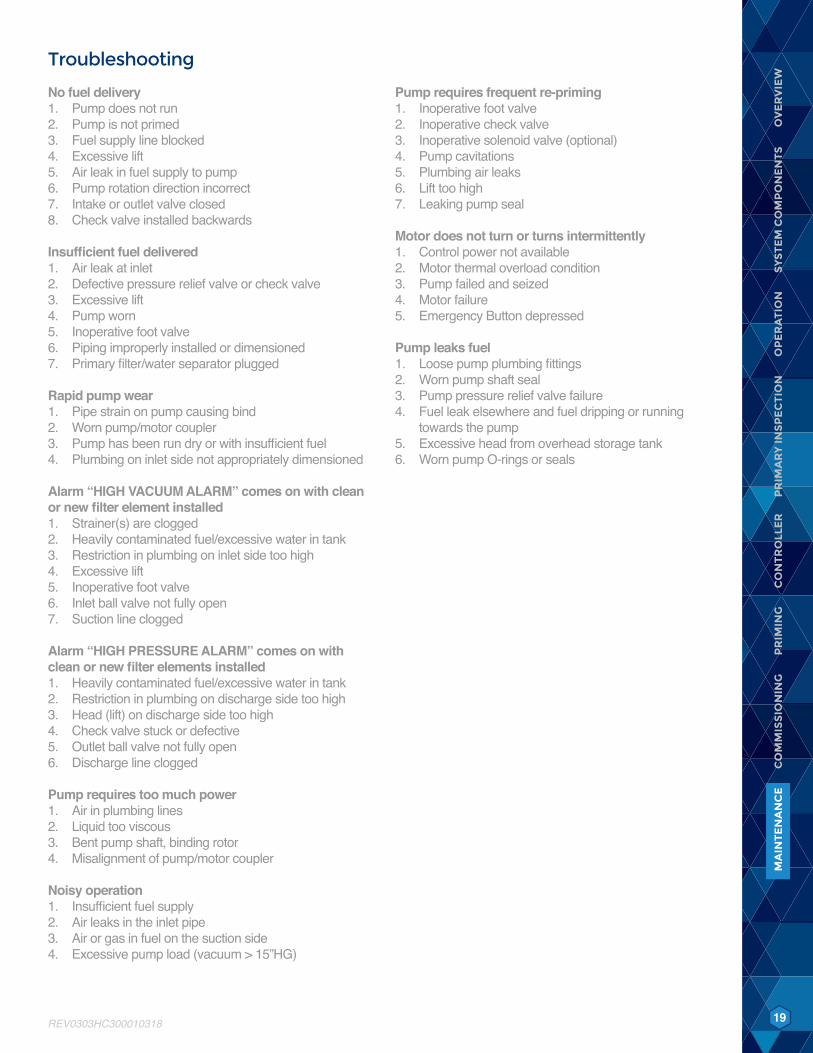
Troubleshooting
No fuel delivery1. Pump does not run2. Pump is not primed3. Fuel supply line blocked4. Excessive lift5. Air leak in fuel supply to pump6. Pump rotation direction incorrect7. Intake or outlet valve closed8. Check valve installed backwards
Insufficient fuel delivered1. Air leak at inlet2. Defective pressure relief valve or check valve3. Excessive lift4. Pump worn5. Inoperative foot valve6. Piping improperly installed or dimensioned7. Primary filter/water separator plugged
Rapid pump wear1. Pipe strain on pump causing bind2. Worn pump/motor coupler3. Pump has been run dry or with insufficient fuel4. Plumbing on inlet side not appropriately dimensioned
Alarm “HIGH VACUUM ALARM” comes on with clean or new filter element installed1. Strainer(s) are clogged2. Heavily contaminated fuel/excessive water in tank3. Restriction in plumbing on inlet side too high4. Excessive lift5. Inoperative foot valve6. Inlet ball valve not fully open7. Suction line clogged
Alarm “HIGH PRESSURE ALARM” comes on with clean or new filter elements installed1. Heavily contaminated fuel/excessive water in tank2. Restriction in plumbing on discharge side too high3. Head (lift) on discharge side too high4. Check valve stuck or defective5. Outlet ball valve not fully open6. Discharge line clogged
Pump requires too much power1. Air in plumbing lines2. Liquid too viscous3. Bent pump shaft, binding rotor4. Misalignment of pump/motor coupler
Noisy operation1. Insufficient fuel supply2. Air leaks in the inlet pipe3. Air or gas in fuel on the suction side4. Excessive pump load (vacuum > 15”HG)
Pump requires frequent re-priming1. Inoperative foot valve2. Inoperative check valve3. Inoperative solenoid valve (optional)4. Pump cavitations5. Plumbing air leaks6. Lift too high7. Leaking pump seal
Motor does not turn or turns intermittently1. Control power not available2. Motor thermal overload condition3. Pump failed and seized4. Motor failure5. Emergency Button depressed
Pump leaks fuel1. Loose pump plumbing fittings2. Worn pump shaft seal3. Pump pressure relief valve failure4. Fuel leak elsewhere and fuel dripping or running
towards the pump5. Excessive head from overhead storage tank6. Worn pump O-rings or seals
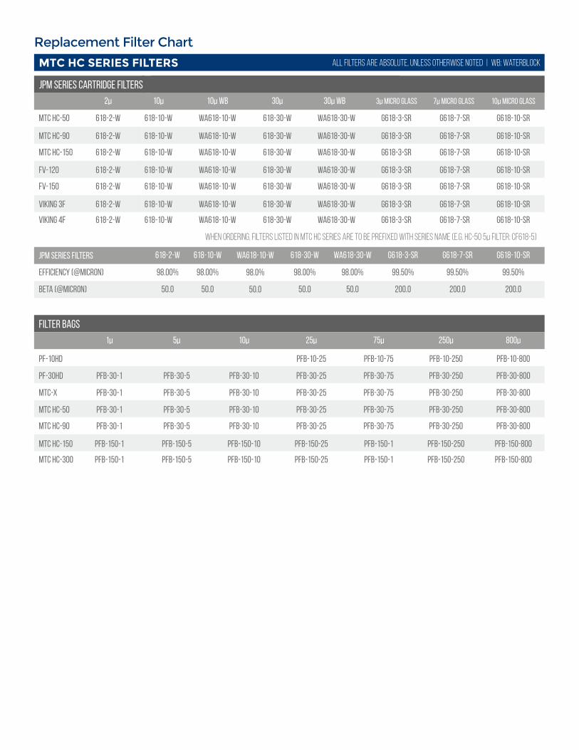
Replacement Filter Chart
Efficiency (@micron)
JPM Series Filters
Beta (@micron)
618-2-w 618-10-w WA618-10-w 618-30-w WA618-30-w G618-3-SR G618-7-SR G618-10-SR
98.00% 98.00% 98.0% 98.00% 98.00% 99.50% 99.50% 99.50%
50.0 50.0 50.0 50.0 50.0 200.0 200.0 200.0
MTC HC-50
MTC HC-90
MTC HC-150
2µ 10µ 10µ WB 30µ 30µ WB 3µ Micro Glass 7µ Micro Glass
618-2-w 618-10-w WA618-10-w 618-30-w WA618-30-w G618-3-SR G618-7-SR
618-2-w 618-10-w WA618-10-w 618-30-w WA618-30-w G618-3-SR G618-7-SR
10µ Micro Glass
G618-10-SR
G618-10-SR
Viking 4F 618-2-w 618-10-w WA618-10-w 618-30-w WA618-30-w G618-3-SR G618-7-SR G618-10-SR
FV-150
Viking 3F
618-2-w 618-10-w WA618-10-w 618-30-w WA618-30-w G618-3-SR G618-7-SR
618-2-w 618-10-w WA618-10-w 618-30-w WA618-30-w G618-3-SR G618-7-SR
G618-10-SR
G618-10-SR
FV-120 618-2-w 618-10-w WA618-10-w 618-30-w WA618-30-w G618-3-SR G618-7-SR G618-10-SR
618-2-w 618-10-w WA618-10-w 618-30-w WA618-30-w G618-3-SR G618-7-SR G618-10-SR
When ordering, filters listed in MTC HC Series are to be prefixed with series name (E.G. HC-50 5µ Filter: CF618-5)
Filter Bags
PF-10HD
PF-30HD
MTC-X
MTC HC-50
1µ 25µ
PFB-30-1
PFB-30-1
PFB-30-1
MTC HC-150 PFB-150-1
5µ 10µ 75µ 250µ 800µ
PFB-30-1
PFB-30-5
PFB-30-5
PFB-30-5
PFB-150-5
PFB-30-5
PFB-30-10
PFB-30-10
PFB-30-10
PFB-150-10
PFB-30-10
PFB-10-25
PFB-30-25
PFB-30-25
PFB-30-25
PFB-150-25
PFB-30-25
PFB-10-75
PFB-30-75
PFB-30-75
PFB-30-75
PFB-150-1
PFB-30-75
PFB-10-250
PFB-30-250
PFB-30-250
PFB-30-250
PFB-150-250
PFB-30-250
PFB-10-800
PFB-30-800
PFB-30-800
PFB-30-800
PFB-150-800
PFB-30-800MTC HC-90
MTC HC SERIES FILTERS
JPM SERIES Cartridge Filters
all filters are absolute, unless otherwise noted | wb: waterblock
MTC HC-300 PFB-150-1 PFB-150-5 PFB-150-10 PFB-150-25 PFB-150-1 PFB-150-250 PFB-150-800
AXI INTERNATIONAL WARRANTY - LIMITED WARRANTY
AXI International makes every effort to assure that its products meet high quality and durability standards and expressly warrants the products described herein against defects in material and workmanship for a period of one (1) year from the date of purchase. This warranty is not intended to supplant normal inspection, care and service of the products covered by the user, and shall not obligate AXI International to provide free service during the warranty period to correct breakage, maladjustment, or other dif culties arising out of abuse, misuse, or improper care and maintenance of such products. Our express warranty is subject to the following terms and conditions:
This warranty shall only extend to and is only for the benefit of original purchaser(s), or end customer(s) who use the products covered hereby and subject to the terms and conditions herein. This warranty is not an on-site warranty. Travel requests will be at the discretion of AXI International. Defective systems and ancillary products will require a return authorization number and shipping to AXI International’s factory in Fort Myers, FL. Any warranty claim received by AXI International after one (1) year from the date of purchase will not be honored even if it is claimed that the defect occurred prior to one (1) year from the date of purchase. Claims outside of this one (1) year period, and for claims not listed within, payment, repair, or service will be awarded at the sole and exclusive discretion of AXI International.
This Warranty shall NOT apply to the following:1. Damage or deterioration caused by normal wear and tear.2. Failures caused by any external cause or act of God, such as accident, collision, theft, vandalism, riots, wars, re, freezing, lightning, earth-quakes, windstorms, hail, volcanic eruptions, oods, tornados or hurricanes.3. Failures due to alterations, adjustments, unauthorized changes to the product(s), neglect or improper storage, repair and/or maintenance.4. Failures due to abuse or application of the product(s) for uses other than for which it/they are designed or intended by AXI International, including but not limited to, improper installation or location in a harsh, corrosive or saltwater environment.5. Failures resulting from attachments, accessory items, and parts not sold by AXI International.6. Repairs by any party other than those authorized by AXI International.7. Failures resulting from user’s delay in making the product available for inspection by AXI International after notifying AXI International of a potential product problem. 8. Cosmetic damage, discoloration, rusting, corrosion or scratches from applied paint.9. Replacement of consumables such as, but not limited to, fuses, lamps, lters, etc.10. Additional expenses for repair after normal business hours, i.e., overtime or holiday labor rates.11. Expenses for rental of equipment during downtime and/or performance of warranty repairs.12. Expenses related to investigating performance complaints and/or troubleshooting where no manufacturing defect is found.
In addition to the limitations above, this warranty shall not apply to products (1) which have been tampered with, altered or repaired by anyone other than AXI International without the express prior written consent of AXI International (2) which have been installed improperly or subject to misuse, abuse, accident, negligence of others, improper operation or maintenance, neglect or modi cation, or (3) which have had the serial number altered, defaced or removed.The liability of AXI International under this warranty is limited to the repair or replacement of the defective product. AXI International assumes NO LIABILITY for labor charges or other costs incurred by any purchaser incidental to the service, adjustment, repair, return, removal or replacement of products. AXI INTERNATIONAL ASSUMES NO LIABILITY FOR ANY GENERAL , SPECIAL, INCIDENTAL, CONSEQUENTIAL, CONTINGENT OR OTHER DAMAGES UNDER ANY WARRANTY, EXPRESS OR IMPLIED, OF MERCHANTABILITY, FITNESS FOR A PARTICULAR PURPOSE OR OTHERWISE, WITH THE RESPECT TO THE PRODUCTS COVERED BY THIS WARRANTY POLICY, EXCEPT AS EXPRESSLY PROVIDED FOR HEREIN. AXI INTERNATIONAL ASSUMES NO LIABILITY FOR ANY GENERAL, SPECIAL, INCIDENTAL, CONSEQUENTIAL, CONTINGENT OR OTHER DAMAGES EVEN IF SUCH DAMAGES ARE A DIRECT RESULT OFAXI INTERNATIONAL’S NEGLIGENCE. NO EMPLOYEE, AGENT, REPRESENTATIVE OR DISTRIBUTOR IS AUTHORIZED TO MAKE ANY WARRANTY ON BEHALF OF AXI INTERNATIONAL OTHER THAN THE EXPRESS WARRANTY PROVIDED FOR HEREIN.
AXI International reserves the right at any time to make changes in the design, material, function and specifications of its products. Any such changes shall not obligate AXI International to make similar changes in such products that were previously manufactured.
To the fullest extent permitted by law, any claims against AXI International are limited to the remedies as expressly set forth in this warranty and any other further claims, such as but not limited to, compensation for any damage incurred other than to the AXI International product, are hereby excluded.
Warranty Claim Procedure
To make a claim under this warranty, please call AXI International at +1-239-690-9589 or 1-877-425-4239, and provide: Name and location where unit was purchased, the date and receipt of purchase, model number, serial number, and a detailed explanation of the problem you are experiencing. The Customer Service Representative may, at the discretion of AXI International, arrange for a Field Engineer to inspect your system. If the inspection reveals a defect covered by its limited warranty, AXI International will either repair or replace the defective parts or products. AXI International assumes no liability, if upon inspection, AXI International or its representative determines that there is no defect or that the damage to the system resulted from causes not within the scope of this limited warranty and customer shall be responsible standard rates incurred by AXI International, as established from time to time by AXI International.
For service and sales, please contact AXI International:
AXI International | 5400 Division Drive Fort Myers, FL 33905Tel: +1-239-690-9589 | Toll Free: +1-877-425-4239 | Fax: +1-239-690-1195Email: [email protected] | Internet: www.axi-international.com
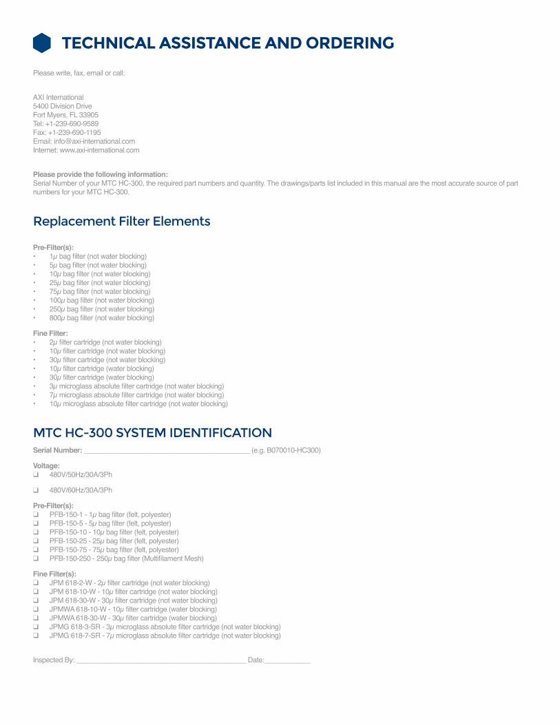
TECHNICAL ASSISTANCE AND ORDERING
Please write, fax, email or call:
AXI International5400 Division DriveFort Myers, FL 33905Tel: +1-239-690-9589Fax: +1-239-690-1195Email: [email protected] Internet: www.axi-international.com
Please provide the following information:Serial Number of your MTC HC-300, the required part numbers and quantity. The drawings/parts list included in this manual are the most accurate source of part numbers for your MTC HC-300.
Replacement Filter Elements
Pre-Filter(s):• 1µ bag filter (not water blocking)• 5µ bag filter (not water blocking)• 10µ bag filter (not water blocking)• 25µ bag filter (not water blocking)• 75µ bag filter (not water blocking)• 100µ bag filter (not water blocking)• 250µ bag filter (not water blocking)• 800µ bag filter (not water blocking)
Fine Filter:• 2µ filter cartridge (not water blocking)• 10µ filter cartridge (not water blocking)• 30µ filter cartridge (not water blocking)• 10µ filter cartridge (water blocking)• 30µ filter cartridge (water blocking)• 3µ microglass absolute filter cartridge (not water blocking)• 7µ microglass absolute filter cartridge (not water blocking)• 10µ microglass absolute filter cartridge (not water blocking)
MTC HC-300 SYSTEM IDENTIFICATIONSerial Number: ___________________________________________ (e.g. B070010-HC300)
Voltage: ❑ 480V/50Hz/30A/3Ph
❑ 480V/60Hz/30A/3Ph
Pre-Filter(s): ❑ PFB-150-1 - 1µ bag filter (felt, polyester) ❑ PFB-150-5 - 5µ bag filter (felt, polyester) ❑ PFB-150-10 - 10µ bag filter (felt, polyester) ❑ PFB-150-25 - 25µ bag filter (felt, polyester) ❑ PFB-150-75 - 75µ bag filter (felt, polyester) ❑ PFB-150-250 - 250µ bag filter (Multifilament Mesh)
Fine Filter(s): ❑ JPM 618-2-W - 2µ filter cartridge (not water blocking) ❑ JPM 618-10-W - 10µ filter cartridge (not water blocking) ❑ JPM 618-30-W - 30µ filter cartridge (not water blocking) ❑ JPMWA 618-10-W - 10µ filter cartridge (water blocking) ❑ JPMWA 618-30-W - 30µ filter cartridge (water blocking) ❑ JPMG 618-3-SR - 3µ microglass absolute filter cartridge (not water blocking) ❑ JPMG 618-7-SR - 7µ microglass absolute filter cartridge (not water blocking)
Inspected By: ____________________________________________ Date:____________

NOTES:
22 REV0305220001200AXI.International AXInternational AXIFuel AXIFuel
1.239.690.95891.877.425.4239 Toll Free www.AXI-International.com
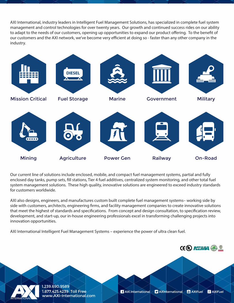
Mission Critical Fuel Storage Marine Government
Mining Agriculture Power Gen Railway
Military
On-Road
AXI International, industry leaders in Intelligent Fuel Management Solutions, has specialized in complete fuel system management and control technologies for over twenty years. Our growth and continued success rides on our ability to adapt to the needs of our customers, opening up opportunities to expand our product o�ering. To the bene�t of our customers and the AXI network, we’ve become very e�cient at doing so - faster than any other company in the industry.
Our current line of solutions include enclosed, mobile, and compact fuel management systems, partial and fully enclosed day tanks, pump sets, �ll stations, Tier 4 fuel additives, centralized system monitoring, and other total fuel system management solutions. These high quality, innovative solutions are engineered to exceed industry standards for customers worldwide.
AXI also designs, engineers, and manufactures custom built complete fuel management systems– working side by side with customers, architects, engineering �rms, and facility management companies to create innovative solutions that meet the highest of standards and speci�cations. From concept and design consultation, to speci�cation review, development, and start-up, our in-house engineering professionals excel in transforming challenging projects into innovation opportunities.
AXI International Intelligent Fuel Management Systems – experience the power of ultra clean fuel.


![HD Видеокамера HC-V770 HC-V760 HC-VX870 HC-VX870M · hc-v770 [v770] Серияv770 / серия [v770] hc-v770m [v770m] hc-v760 [v760] – Данная инструкция](https://img.dokumen.tips/doc/110x75/5e697831d35b2b14c40ee20b/hd-hc-v770-hc-v760-hc-vx870-hc-vx870m-hc-v770-v770-v770.jpg)