Embed Size (px)
Citation preview

MANUAL NO.
HW1480687 4
MOTOMAN-MHJINSTRUCTIONS
TYPE:YR-MH0000J-A00
Upon receipt of the product and prior to initial operation, read these instructions thoroughly, and retain for future reference.
MOTOMAN INSTRUCTIONS
MOTOMAN-MHJ INSTRUCTIONS
FS100 INSTRUCTIONSFS100 OPERATOR’S MANUALFS100 MAINTENANCE MANUAL
1/51
160477-1CD3

ii
HW1480687
HW1480687
MANDATORY
• This instruction manual is intended to explain operating instructionsand maintenance procedures primarily for the MOTOMAN-MHJ.
• General items related to safety are listed in the Chapter 1: Safety ofthe FS100 Instructions. To ensure correct and safe operation,carefully read the FS100 Instructions before reading this manual.
CAUTION
• Some drawings in this manual are shown with the protective coversor shields removed for clarity. Be sure all covers and shields arereplaced before operating this product.
• The drawings and photos in this manual are representativeexamples and differences may exist between them and thedelivered product.
• YASKAWA may modify this model without notice when necessarydue to product improvements, modifications, or changes inspecifications. If such modification is made, the manual number willalso be revised.
• If your copy of the manual is damaged or lost, contact a YASKAWArepresentative to order a new copy. The representatives are listedon the back cover. Be sure to tell the representative the manualnumber listed on the front cover.
• YASKAWA is not responsible for incidents arising from unauthorizedmodification of its products. Unauthorized modification voids yourproduct’s warranty.
2/51

iii
HW1480687
HW1480687
Notes for Safe OperationRead this manual carefully before installation, operation, maintenance, or inspection of the FS100 and your manipulator.
In this manual, the Notes for Safe Operation are classified as “DANGER”, “WARNING”, “CAUTION”, “MANDATORY”, or “PROHIBITED”.
Even items described as “CAUTION” may result in a serious accident in some situations.
At any rate, be sure to follow these important items.
DANGERIndicates an imminent hazardous situation which, if not avoided, could result in death or serious injury to personnel.
WARNINGIndicates a potentially hazardous situation which, if not avoided, could result in death or serious injury to personnel.
CAUTIONIndicates a potentially hazardous situation which, if not avoided, could result in minor or moderate injury to personnel and damage to equipment. It may also be used to alert against unsafe practices.
MANDATORYAlways be sure to follow explicitly the items listed under this heading.
PROHIBITEDMust never be performed.
NOTETo ensure safe and efficient operation at all times, be sure to follow all instructions, even if not designated as “DAN-GER”, “WARNING” and “CAUTION”.
DANGER
• Maintenance and inspection must be performed by specified personnel.
Failure to observe this caution may result in electric shock or injury.
• For disassembly or repair, contact your Yaskawa representative.
• Do not remove the motor, and do not release the brake.
Failure to observe these safety precautions may result in death or serious injury from unexpected turning of the manipulator's arm.
3/51

iv
HW1480687
HW1480687
WARNING
• Before operating the manipulator, check that servo power is turned off when the emergency stop button on the programing pendant is pressed. When the servo power is turned off, the SERVO ON LED on the programing pendant is turned off.
Injury or damage to machinery may result if the emergency stop circuit cannot stop the manipulator during an emergency. The manipulator should not be used if the emergency stop buttons do not function.
Fig. : Emergency Stop Button
• In the case of not using the programming pendant, be sure to supply the emergency stop button on the equipment. Then before operating the manipulator, check to be sure that the servo power is turned OFF by pressing the emergency stop button. Connect the external emergency stop button to the 5-6 pin and 16-17 pin of the robot system signal connector (CN2).
• Upon shipment of the FS100, this signal is connected by a jumper cable in the dummy connector. To use the signal, make sure to prepare a new connector, and then input it.
If the signal is input with the jumper cable connected, it does not function, which may result in personal injury or equipment damage.
• Once the emergency stop button is released, clear the cell of all items which could interfere with the operation of the manipulator.Then turn the servo power ON.
Injury may result from unintentional or unexpected manipulator motion.
Fig. : Release of EM
Turn
• Observe the following precautions when performing teaching operations within the P-point maximum envelope of the manipulator:
– Be sure to use a lockout device to the safeguarding when going inside. Also, display the sign that the operation is being performed inside the safeguarding and make sure no one closes the safeguarding.
– View the manipulator from the front whenever possible.
– Always follow the predetermined operating procedure.
– Ensure that you have a safe place to retreat in case of emergency.
Improper or unintended manipulator operation may result in injury.
The emergency stop button is located on the programing pendant.
4/51

v
HW1480687
HW1480687
Definition of Terms Used Often in This ManualThe MOTOMAN is the YASKAWA industrial robot product.
The MOTOMAN usually consists of the manipulator, the FS100 controller, manipulator cables, the FS100 programming pendant (optional), and the FS100 programming pendant dummy connector (optional).
In this manual, the equipment is designated as follows:
WARNING
• Confirm that no person is present in the P-point maximum envelope of the manipulator and that you are in a safe location before:
– Turning on the power for the FS100.
– Moving the manipulator with the programming pendant.
– Running the system in the check mode.
– Performing automatic operations.
Injury may result if anyone enters the working envelope of the manipulator during operation. Always press an emergency stop button immediately if there are problems.
CAUTION
• Perform the following inspection procedures prior to conducting manipulator teaching. If problems are found, repair them immediately, and be sure that all other necessary processing has been performed.
– Check for problems in manipulator movement.
– Check for damage to insulation and sheathing of external wires.
• Always return the programming pendant to the hook on the cabinet of the FS100 after use.
The programming pendant can be damaged if it is left in the manipulator's work area, on the floor, or near fixtures.
• Read and understand the Explanation of Warning Labels in the FS100 Instructions before operating the manipulator:
Equipment Manual Designation
FS100 controller FS100
FS100 programming pendant Programming pendant
Cable between the manipulator and the controller
Manipulator Cable
FS100 programming pendant dummy connector
Programming pendant dummy connector
5/51

vi
HW1480687
HW1480687
Explanation of Warning LabelsThe following warning labels are attached to the manipulator.
Always follow the warnings on the labels.
Also, an identification label with important information is placed on the body of the manipulator. Prior to operating the manipulator, confirm the contents.
Nameplate Warning Label B
WARNING
Do not enterrobotwork area.
Warning Label A
WARNING
Moving partsmay causeinjury
Warning label A
Warning label B
Nameplate
MADE IN JAPAN
YASKAWA ELECTRIC CORPORATION
Kitakyushu 806-0004 Japan2-1 Kurosakishiroishi, Yahatanishi-ku,
SERIAL NO.
PAYLOADkg
TYPE
MASS
DATEORDER NO.kg
MOTOMAN-MODEL
6/51

Contents
vii
HW1480687
HW1480687
1 Product Confirmation ...................................................................................................................... 1-1
1.1 Contents Confirmation....................................................................................................... 1-1
1.2 Order Number Confirmation .............................................................................................. 1-2
2 Transport......................................................................................................................................... 2-1
2.1 Transporting Method.......................................................................................................... 2-1
2.1.1 Transporting Posture............................................................................................ 2-1
2.1.2 Using a Forklift...................................................................................................... 2-2
2.1.3 Notes on Transportation....................................................................................... 2-3
3 Installation....................................................................................................................................... 3-1
3.1 Installation of Safeguarding ............................................................................................... 3-2
3.2 Mounting Procedures for Manipulator Base ...................................................................... 3-2
3.2.1 Mounting the Manipulator on the Baseplate ......................................................... 3-3
3.2.2 Mounting the Manipulator Itself Directory on the Floor......................................... 3-4
3.2.3 Ways of Mounting................................................................................................. 3-5
3.3 Location ............................................................................................................................. 3-6
4 Wiring.............................................................................................................................................. 4-1
4.1 Grounding Method............................................................................................................. 4-1
4.2 Manipulator Cable Connection .......................................................................................... 4-2
4.2.1 Connection to the Manipulator.............................................................................. 4-2
4.2.2 Connection to the FS100...................................................................................... 4-2
5 Basic Specifications........................................................................................................................ 5-1
5.1 Basic Specifications........................................................................................................... 5-1
5.2 Part Names and Working Axes.......................................................................................... 5-2
5.3 Manipulator Base Dimensions ........................................................................................... 5-2
5.4 Dimensions and P-Point Maximum Envelope.................................................................... 5-3
5.5 B-Axis Working Envelope .................................................................................................. 5-4
6 Allowable Load for Wrist Axis and Wrist Flange ............................................................................. 6-1
6.1 Allowable Wrist Load ......................................................................................................... 6-1
6.2 Wrist Flange....................................................................................................................... 6-2
7 System Application ......................................................................................................................... 7-1
7.1 Internal User I/O Wiring Harness and Air Lines................................................................. 7-1
7.2 Without Brake at S-, R-, B- and T-Axes Specification ....................................................... 7-2
7/51

Contents
viii
HW1480687
HW1480687
8 Electrical Equipment Specification .................................................................................................. 8-1
8.1 Internal Connections..........................................................................................................8-1
9 Maintenance and Inspection ...........................................................................................................9-1
9.1 Inspection Schedule...........................................................................................................9-1
9.2 Notes on Maintenance Procedures....................................................................................9-4
9.2.1 Battery Pack Replacement ...................................................................................9-4
9.2.2 Notes on Maintenance..........................................................................................9-6
9.2.2.1 Battery Pack Connection for Motors........................................................ 9-6
10 Recommended Spare Parts........................................................................................................ 10-1
11 Parts List .................................................................................................................................... 11-1
11.1 S-Axis Unit ..................................................................................................................... 11-1
11.2 LU-Axis Unit ................................................................................................................... 11-4
11.3 R-Axis Unit ..................................................................................................................... 11-6
11.4 Wrist Unit ....................................................................................................................... 11-8
8/51

1 Product Confirmation1.1 Contents Confirmation
1-1
HW1480687
HW1480687
1 Product Confirmation
1.1 Contents Confirmation
Confirm the contents of the delivery when the product arrives.
Standard delivery includes the following three items (Information for the content of optional goods is given separately):
• Manipulator
• FS100
• Manipulator cables (between the FS100 and the manipulator)
CAUTION
• Confirm that the manipulator and the FS100 have the same order number. Special care must be taken when more than one manipulator is to be installed.
If the numbers do not match, manipulators may not perform as expected and cause injury or damage.
9/51

1 Product Confirmation1.2 Order Number Confirmation
1-2
HW1480687
HW1480687
1.2 Order Number Confirmation
Check that the order number of the manipulator corresponds to the FS100. The order number is indicated on a label as shown below.
Fig. 1-1: Location of Order Number Labels
ORDER. No.
Label (Enlarged View)
THE MANIPULATOR AND THE CONTROLLERSHOULD HAVE SAME ORDER NUMBER. Check that the manipulator
and the FS100 have the same order number.
(a) FS100 (Top View) (b) Manipulator (Back and Side View)
10/51
2 Transport2.1 Transporting Method
2-1
HW1480687
HW1480687
2 Transport
2.1 Transporting Method
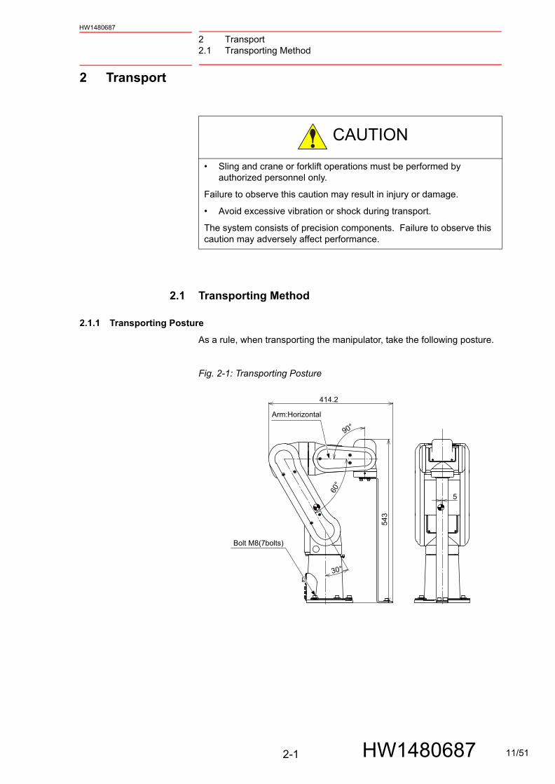
2.1.1 Transporting Posture
As a rule, when transporting the manipulator, take the following posture.
Fig. 2-1: Transporting Posture
CAUTION
• Sling and crane or forklift operations must be performed by authorized personnel only.
Failure to observe this caution may result in injury or damage.
• Avoid excessive vibration or shock during transport.
The system consists of precision components. Failure to observe this caution may adversely affect performance.
414.2
543
5
Arm:Horizontal
Bolt M8(7bolts)
11/51

2 Transport2.1 Transporting Method
2-2
HW1480687
HW1480687
2.1.2 Using a Forklift
When using a forklift, the manipulator should be fixed on a pallet with shipping bolts and brackets as shown in fig. 2-2 “Transport Using a Forklift” .
Insert claws under the pallet and lift it. The pallet must be strong enough to support the manipulator.
Transport the manipulator slowly with due caution in order to avoid overturn or slippage.
Fig. 2-2: Transport Using a Forklift
NOTE• The mass of the manipulator is approximately 15 kg.
• With any transportation equipment, make sure to avoid external force on the arm or motor unit when transporting the manipulator.
Bolt M8(7bolts)
Pallet
Forklift fork entries
12/51
2 Transport2.1 Transporting Method
2-3
HW1480687
HW1480687
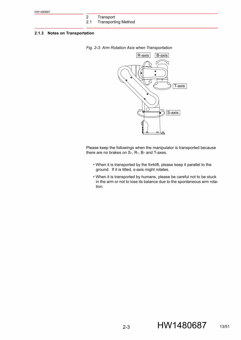
2.1.3 Notes on Transportation
Fig. 2-3: Arm Rotation Axis when Transportation
Please keep the followings when the manipulator is transported because there are no brakes on S-, R-, B- and T-axes.
• When it is transported by the forklift, please keep it parallel to the ground. If it is tilted, s-axis might rotates.
• When it is transported by humans, please be careful not to be stuck in the arm or not to lose its balance due to the spontaneous arm rota-tion.
R-axis B-axis
T-axis
S-axis
13/51

3 Installation
3-1
HW1480687
HW1480687
3 Installation
WARNING
• Sling and crane or forklift operations must be performed by authorized personnel only.
Failure to observe this caution may result in injury or damage.
• Avoid excessive vibration or shock during transport.
The system consists of precision components. Failure to observe this caution may adversely affect performance.
• Install the safeguarding.
Failure to observe this warning may result in injury or damage.
• Install the manipulator in a location where the manipulator’s tool or the workpiece held by the manipulator will not reach the wall, safeguarding, or FS100 when the arm is fully extended.
Failure to observe this warning may result in injury or damage.
• Do not start the manipulator or even turn ON the power before it is firmly anchored.
The manipulator may overturn and cause injury or damage.
• The base for the manipulator should have adequate strength and rigidity.
Failure to observe this warning may result in injury or damage.
CAUTION
• Do not install or operate a manipulator that is damaged or lacks parts.
Failure to observe this caution may cause injury or damage.
14/51

3 Installation3.1 Installation of Safeguarding
3-2
HW1480687
HW1480687
3.1 Installation of Safeguarding
To insure safety, be sure to install the safeguarding.
They prevent unforeseen accidents with personnel and damage to equipment.
The following is quoted for your information and guidance.
Responsibility for Safeguarding (ISO 10218)
The user of a manipulator or robot system shall ensure that safeguarding is provided and used in accordance with Sections 6, 7, and 8 of this standard.
The means and degree of safeguarding, including any redundancies, shall correspond directly to the type and level of hazard presented by the robot system consistent with the robot application.
Safeguarding may include but not be limited to safeguarding devices, barriers, interlock barriers, perimeter guarding, awareness barriers, and awareness signals.
3.2 Mounting Procedures for Manipulator Base
The manipulator should be firmly mounted on a baseplate or foundation strong enough to support the manipulator and withstand repulsion forces during acceleration and deceleration.
Construct a solid foundation with the appropriate thickness to withstand maximum repulsion force of the manipulator. (Refer to table 3-1 “Maximum Repulsion Force of the Manipulator at Emergency Stop” and table 3-2 “Endurance Torque in Operation” .)
A baseplate flatness must be kept at 0.5 mm or less: insufficient flatness of installation surface may deform the manipulator shape and affect its functional abilities.
For installation, refer to chapter 3.2.1 “Mounting the Manipulator on the Baseplate” or chapter 3.2.2 “Mounting the Manipulator Itself Directory on the Floor” .
Table 3-1: Maximum Repulsion Force of the Manipulator at Emergency Stop
Maximum torque in horizontal rotation(S-axis moving direction)
196 N•m(20 kgf•m)
Maximum torque in vertical rotation(LU-axis moving direction)
294 N•m(30 kgf•m)
Table 3-2: Endurance Torque in Operation
Endurance torque in horizontal operation 11.7 N•m(11.4 kgf•m)
Endurance torque in vertical operation 164.6 N•m(16.8 kgf•m)
15/51

3 Installation3.2 Mounting Procedures for Manipulator Base
3-3
HW1480687
HW1480687
3.2.1 Mounting the Manipulator on the Baseplate
The baseplate should be rugged and durable to withstand maximum repulsion force of the manipulator and to ensure that the manipulator and fixture are in the correct relative position.
The thickness of the baseplate is 25 mm or more and an M8 size or larger anchor bolt is recommended.
After anchoring the baseplate firmly on the floor, fix the manipulator base to the baseplate with the hexagon head screw M8 (5 screws, length of 35 mm or more is recommended) using mounting holes on the manipulator base.
The manipulator base is tapped for five mounting holes.
Tighten the hexagon head bolts and anchor bolts securely so that they will not work loose during operation. For details, refer to fig. 3-1 “Mounting the Manipulator on the Baseplate”
Fig. 3-1: Mounting the Manipulator on the Baseplate
12
25 30
60
60
55
P.C.D
.160
63 92.5185
160
0.2 80
0.
1
Spring washer
Washer
Manipulator base
Manipulator base
(Diagonal)
Baseplate
25 mm
or mo
re
Anchor bolt (M8 or more)Baseplate
9 dia. hole (5 holes for fixing)
6 dia. (6 holes for reference)
Hexagon head cap screw M8 (5 screws)
+0.012 0
16/51

3 Installation3.2 Mounting Procedures for Manipulator Base
3-4
HW1480687
HW1480687
3.2.2 Mounting the Manipulator Itself Directory on the Floor
The floor should be strong enough to support the manipulator.
Construct a solid foundation with the appropriate thickness to withstand maximum repulsion force of the manipulator shown in table 3-1 “Maximum Repulsion Force of the Manipulator at Emergency Stop” .
As a rough standard, if there is a concrete thickness (floor) of 150 mm or more, the manipulator base can be fixed directly to the floor with anchor bolts M8.
Before mounting the manipulator, however, check that the floor is level and that all cracks, etc. are repaired.
Any thickness less than 150 mm is insufficient for mounting, even if the floor is concrete.
Fig. 3-2: Mounting the Manipulator Directory on the Floor
M8 anchor bolt (5 bolts)
Concrete floor
45 m
m o
r mor
e
150
mm
or m
ore
17/51

3 Installation3.2 Mounting Procedures for Manipulator Base
3-5
HW1480687
HW1480687
3.2.3 Ways of Mounting
The manipulator can be mounted in three different ways: floor-mounted (standard), wall-mounted, and ceiling-mounted ways are available.
1. For ceiling-mounted way, the base of the manipulator should be fixed with the hexagon head screw M8 (5 screws, length of 35 mm or more is recommended). And tighten them with the tightening torque of 24.5 N•m.
2. When performing ceiling installations, for safety purposes, take measures to the manipulator base to keep the manipulator from falling. Refer to fig. 3-3 “Precaution Against Falling” for details.
Fig. 3-3: Precaution Against Falling
NOTE
• In case of installing on the ceiling, inform your Yaskawa representative of the matter when placing an order.
• Be sure to contact your Yaskawa representative (listed on the back cover of this instruction manual) to perform a ceiling installation on site.
Support for fall prevention
Manipulator base
18/51

3 Installation3.3 Location
3-6
HW1480687
HW1480687
3.3 Location
When installing the manipulator, satisfy the following environmental conditions.
• Ambient temperature: 0° to 45°C
• Humidity: 20 to 80%RH at constant temperature
• Free from exposure to water, oil, or dust
• Free from corrosive gas or liquid, or explosive gas or liquid
• Free from excessive vibration (Vibration acceleration: 4.9 m/s2
[0.5 G] or less)
• Free from large electrical noise (plasma)
• Flatness for installation is 0.5 mm or less
19/51

4 Wiring4.1 Grounding Method
4-1
HW1480687
HW1480687
4 Wiring
4.1 Grounding Method
Follow local regulations for grounding line size. A line of 5.5 mm2 or more is recommended. Refer to fig. 4-1 “Grounding Method” to connect the ground line directly to the manipulator.
Fig. 4-1: Grounding Method
WARNING
• Ground resistance must be 100 W or less.
Failure to observe this warning may result in fire or electric shock.
• Before wiring, make sure to turn OFF the primary power supply, and put up a warning sign. (ex. DO NOT TURN THE POWER ON.)
Failure to observe this warning may result in fire or electric shock.
CAUTION
• Wiring must be performed by authorized or certified personnel.
Failure to observe this caution may result in fire or electric shock.
NOTE
• Do not use this line sharing with other ground lines or grounding electrodes for other electric power, motor power, welding devices, etc.
• Where metal ducts, metallic conduits, or distributing racks are used for cable laying, ground in accordance with Elec-tric Equipment Technical Standards.
View A
A
Bolt M8 (for grounding)Delivered with the manipulator
20/51

4 Wiring4.2 Manipulator Cable Connection
4-2
HW1480687
HW1480687
4.2 Manipulator Cable Connection
Two manipulator cables are delivered with the manipulator; an encoder cable (1BC) and a power cable (2BC). (Refer to fig. 4-2 “Manipulator Cables” .)
Connect these cables to the manipulator base connectors and to the FS.
Please refer to fig. 4-3(a) “Manipulator Cable Connection (Manipulator Side)” and fig. 4-3(b) “Manipulator Cable Connection (FS100 Side)” .
4.2.1 Connection to the Manipulator
Before connecting two cables to the manipulator, verify the numbers on both manipulator cables and the connectors on the connector base of the manipulator.
When connecting, adjust the cable connector positions to the main key positions of the manipulator, and insert cables in the order of 2BC, then 1BC. After inserting the cables, fix them with screws.
4.2.2 Connection to the FS100
Before connecting two cables to the manipulator, verify the numbers on both manipulator cables and the connectors on the connector base of the manipulator.
When connecting, adjust the cable connector positions to the main key positions of the manipulator, then connect 2BC to X21 on the FS first, then connect 1BC to X11.
After inserting the cables, depress the lever until it clicks.
CAUTION
• Do not cover the cable with heat insulating material, and avoid multiple cabling.
21/51

4 Wiring4.2 Manipulator Cable Connection
4-3
HW1480687
HW1480687
Fig. 4-2: Manipulator Cables
Fig. 4-3(a): Manipulator Cable Connection (Manipulator Side)
Fig. 4-3(b): Manipulator Cable Connection (FS100 Side)
FS100 Side Manipulator Side
1BC Encoder Cable
2BC Power Cable
1BCX
11
2BC
X21
FS100 Side Manipulator Side
X11 1BC
2BCX21
Connector Details(Manipulator Side)
1BC
2BC
Connector Details (FS100 side)
X21 X11
22/51

5 Basic Specifications5.1 Basic Specifications
5-1
HW1480687
HW1480687
5 Basic Specifications
5.1 Basic Specifications
Table 5-1: Basic Specifications1)
Item Model MOTOMAN-MHJ (YR-MH0000J-A00)
Configuration Vertically Articulated
Degree of Freedom 6
Payload 1 kg (Max. 2 kg)
Repeatability2) ±0.03 mm
Range of Motion S-axis (turning) -160° − +160°
L-axis (lower arm) -90° − +110°
U-axis (upper arm) -105° − +290°
R-axis (wrist roll) -180° − +180°
B-axis (wrist pitch/yaw) -130° − +130°
T-axis (wrist twist) -360° − +360°
MaximumSpeed
S-axis 2.79 rad/s, 160°/s
L-axis 2.27 rad/s, 130°/s
U-axis 3.49rad/s, 200°/s
R-axis 5.23 rad/s, 300°/s
B-axis 6.98 rad/s, 400°/s
T-axis 8.72 rad/s, 500°/s
AllowableMoment3)
R-axis 3.33 N•m (0.34 kgf•m)
B-axis 3.33 N•m (0.34 kgf•m)
T-axis 0.98 N•m (0.1 kgf•m)
AllowableInertia3) (GD2/4)
R-axis 0.058 kg•m2
B-axis 0.058 kg•m2
T-axis 0.005 kg•m2
Approx. Mass 15 kg
AmbientConditions
Temperature 0°C - 45°C
Humidity 20 to 80% RH at constant temperature
Vibration Acceleration Less than 4.9 m/s2 (0.5 G)
Mounting Method Floor-mounted, Ceiling-mounted
Others • Free from explosive and corrosive gas or liquid.• Free from water, oil, or dust.• Free from excessive electrical noise (plasma).
Power Capacity 0.5 kVA
1 SI units are used in this table. However, gravitational unit is used in (). 2 Conformed to ISO9283. 3 Refer to chapter 6.1 “Allowable Wrist Load” for details on the allowable moment and
the allowable inertia.
23/51

5 Basic Specifications5.2 Part Names and Working Axes
5-2
HW1480687
HW1480687
5.2 Part Names and Working Axes
Fig. 5-1: Part Names and Working Axes
5.3 Manipulator Base Dimensions
Fig. 5-2: Manipulator Base Dimensions
Upper arm(U-arm)
Wrist
Lower arm(L-arm)
Rotary head(S-head)
Base
S-
L+L-
U-
U+R+
R-
B+
B-
T+
T-
S+
(Diagonal)
View A
25 30
60
60
55
P.C.D
.160
63 92.5
185
80
0.1
160
0.2
A
+0.012 0 6 dia. (6 holes for reference)
9 dia. hole (5 holes for fixing)
24/51

5 Basic Specifications5.4 Dimensions and P-Point Maximum Envelope
5-3
HW1480687
HW1480687
5.4 Dimensions and P-Point Maximum Envelope
Fig. 5-3: Dimensions and P-Point Maximum Envelope
P-point maximum envelope
P-point maximum envelope(When the payload is 1kg)
P-point maximum envelope(When the payload is 2kg)
P-point maximum envelope(When the payload is 2kg)
P-point maximum envelope(When the payload is 1kg)
160
160
270
168
183
500 500
273
209
63545
545
240
270
234
364
545
20927
555
29090 110
105
R209
R500
R545
If more than 1kg, range ofmotion is different.Please use within range ofmotion for payload.
*1
*1
*1
P-point
25/51

5 Basic Specifications5.5 B-Axis Working Envelope
5-4
HW1480687
HW1480687
5.5 B-Axis Working Envelope
B-axis moves within the defined degrees toward the center of U-axis as shown in fig. 5-4 “B-Axis Working Envelope” .
Fig. 5-4: B-Axis Working Envelope
U-axiscenter of rotation
B-axiscenter of rotation
S-axiscenter of rotation
L-axiscenter of rotation
130
130
26/51

6 Allowable Load for Wrist Axis and Wrist Flange6.1 Allowable Wrist Load
6-1
HW1480687
HW1480687
6 Allowable Load for Wrist Axis and Wrist Flange
6.1 Allowable Wrist Load
The allowable wrist load is 2 kg including its grip mass.
As shown in table 6-1 “Allowable Total Moment of Wrist” , the moment of each axis is limited. Observe the conditions described in this section in applying load on the wrist.
When the volume load is small, refer to the moment arm rating shown in fig. 6-1 “Moment Arm Rating” .
The allowable total moment of inertia is calculated when the moment is at the maximum. Contact your Yaskawa Representative beforehand when the moment of inertia is the only load or the load moment is smaller than moment of inertia.
Also, if force is applied to the wrist instead of the load, contact your Yaskawa Representative beforehand.
Fig. 6-1: Moment Arm Rating
Table 6-1: Allowable Total Moment of Wrist
Axis Moment N•m (kgf•m)1)
1 ( ): Gravitational unit
GD2/4 Total Moment of Inertia kg•m2
R-axisB-axisT-axis
3.33 (0.34)3.33 (0.34)0.98 (0.1)
0.0580.0580.005
LT(mm)
LT(mm)
LB(mm)2kg1kg
0.5kg
100
100 200 300 400
100
R-, T-axis center of rotation
B-axis center of rotation
P-point
27/51

6 Allowable Load for Wrist Axis and Wrist Flange6.2 Wrist Flange
6-2
HW1480687
HW1480687
6.2 Wrist Flange
The wrist flange dimensions are shown in fig. 6-2 “Wrist Flange” .
It is recommended that the attachment be mounted inside the fitting in order to identify the alignment marks. Fitting depth shall be 6mm or less.
Fig. 6-2: Wrist Flange
NOTE Wash off anti-corrosive paint (yellow) on the wrist flange surface with thinner or light oil before mounting the tools.
12.5 0.02 12.5 0.02
45
P.C.D
.25
+0.01205 dia. hole
(depth: 5)
+0.0
150
10 d
ia.
hol
e
Tapped hole M5(depth: 9) (pitch: 0.8)(4 holes)
6 (fitting depth)
28/51
7 System Application7.1 Internal User I/O Wiring Harness and Air Lines
7-1
HW1480687
HW1480687
7 System Application
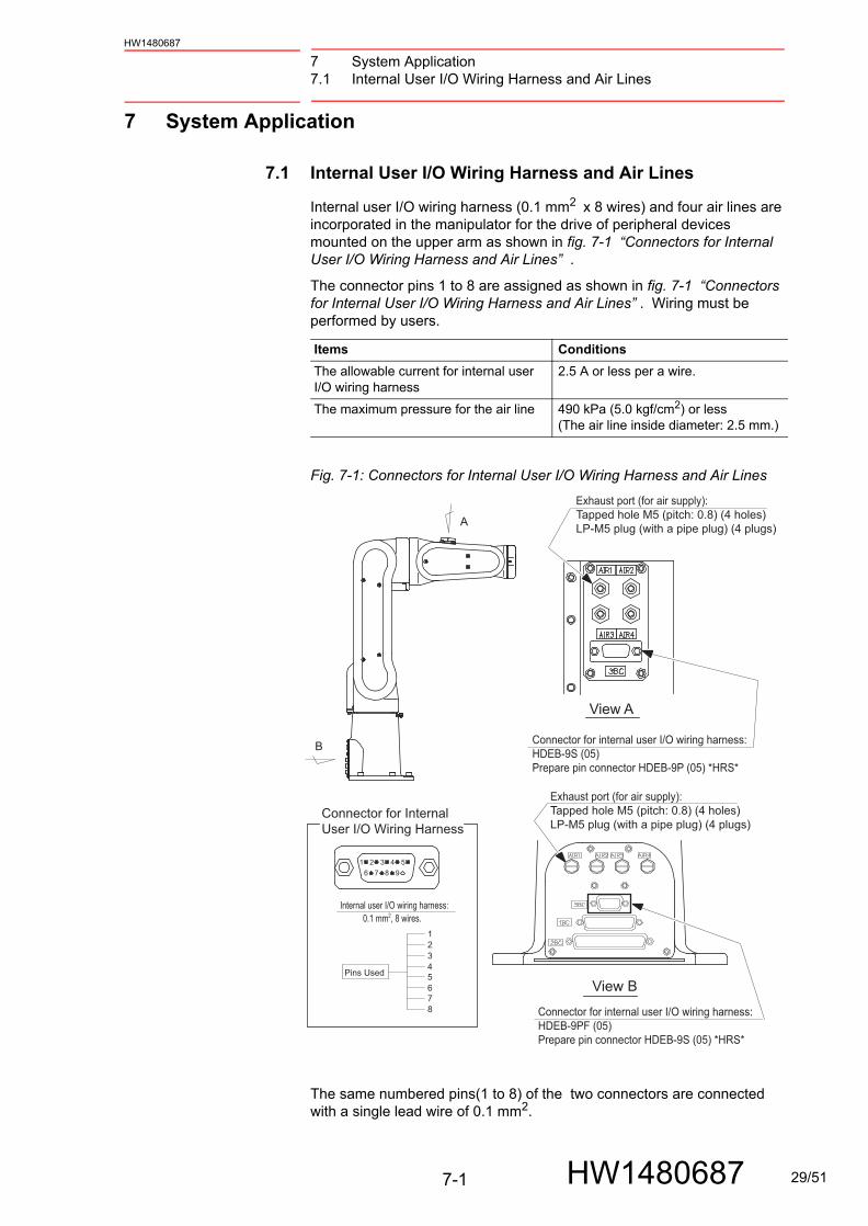
7.1 Internal User I/O Wiring Harness and Air Lines
Internal user I/O wiring harness (0.1 mm2 x 8 wires) and four air lines are incorporated in the manipulator for the drive of peripheral devices mounted on the upper arm as shown in fig. 7-1 “Connectors for Internal User I/O Wiring Harness and Air Lines” .
The connector pins 1 to 8 are assigned as shown in fig. 7-1 “Connectors for Internal User I/O Wiring Harness and Air Lines” . Wiring must be performed by users.
Fig. 7-1: Connectors for Internal User I/O Wiring Harness and Air Lines
The same numbered pins(1 to 8) of the two connectors are connected with a single lead wire of 0.1 mm2.
Items Conditions
The allowable current for internal userI/O wiring harness
2.5 A or less per a wire.
The maximum pressure for the air line 490 kPa (5.0 kgf/cm2) or less(The air line inside diameter: 2.5 mm.)
1
16 7 8 9
2 3 4 5
2345678
A
B
Exhaust port (for air supply):Tapped hole M5 (pitch: 0.8) (4 holes) LP-M5 plug (with a pipe plug) (4 plugs)
Exhaust port (for air supply):Tapped hole M5 (pitch: 0.8) (4 holes) LP-M5 plug (with a pipe plug) (4 plugs)
Connector for internal user I/O wiring harness:HDEB-9S (05) Prepare pin connector HDEB-9P (05) *HRS*
Connector for internal user I/O wiring harness:HDEB-9PF (05) Prepare pin connector HDEB-9S (05) *HRS*
Connector for Internal User I/O Wiring Harness
Internal user I/O wiring harness:
Pins Used
View A
View B
0.1 mm2, 8 wires.
29/51

7 System Application7.2 Without Brake at S-, R-, B- and T-Axes Specification
7-2
HW1480687
HW1480687
7.2 Without Brake at S-, R-, B- and T-Axes Specification
The S-, R-, B- and T-axes on MOTOMAN-MHJ are not equipped with brakes. The posture of the manipulator might change if the SERVO is turned OFF during the postures that gravitational force is likely to be applied to these axes. Taking this, the following alarms occurrs if the power supply is turned ON or the SERVO is turned ON when the manipulator is taking above mentioned postures. To avoid these alarms to occur, keep the manipulator in the posture that the gravity will not be applied to those axes.
• DROP-VALUE OUT OF RANGE (AL-4511)This alarm occurs when the difference in the rmanipulator’s position pulse of the previous and the current SERVO OFF is more then 100 pulse. Reset the alarm and turn ON the SERVO again.
• SERVO ON SPEED ERROR (AL-4307)This alarm occurs when the motor is still moving even though the SERVO is already turned OFF. Confirm that the manipulator is completely stopped, then turn ON the SERVO again.
• ABSOLUTE DATA OUT OF RANGE (AL-4107)This alarm occurs when the difference in the position pulse when the power is turned OFF and when the power is turned ON is more than 4096. Reset the alarm and move the manipulator to the home position, then confirm the position.
R-axis B-axis
T-axis
S-axis
30/51

8 Electrical Equipment Specification8.1 Internal Connections
8-1
HW1480687
HW1480687
8 Electrical Equipment Specification
8.1 Internal Connections
Diagram for internal connections of the manipulator are shown in fig. 8-1(a) “Internal Connection Diagram” and fig. 8-1(b) “Internal Connection Diagram”
31/51

8 Electrical Equipment Specification8.1 Internal Connections
8-2
HW1480687
HW1480687
Fig. 8-1(a): Internal Connection Diagram
No.3CN
CN-1
No.4CN
-2-3
-3-4
-2CN-1
0V
OBTBAT
FG2
DATA-2DATA+2
+5V
0V(OBT)3.6V(BAT)
PG L-AXIS
No.5CN
CN-1
No.6CN
-2-3
-3-4
-2CN-1
0V
OBTBAT
FG3
DATA-3DATA+3
+5V
0V(OBT)3.6V(BAT)
PG U-AXIS
No.1CN
CN-1
No.2CN
-2-3
-3-4
-2CN-1
0VFG1
DATA-1DATA+1
+5V
0V(OBT)3.6V(BAT)
PG S-AXIS
No.7CN
CN-1
No.8CN
-2-3
-3-4
-2CN-1
0VFG4
DATA-4DATA+4
+5V
0V(OBT)3.6V(BAT)
PG R-AXIS
No.9CN
CN-1
No.10CN
-2-3
-3-4
-2CN-1
0VFG5
DATA-5DATA+5
+5V
0V(OBT)3.6V(BAT)
PG B-AXIS
No.11CN
CN-1
No.12CN
-2-3
-3-4
-2CN-1
0VFG6
DATA-6DATA+6
+5V
0V(OBT)3.6V(BAT)
PG T-AXIS
OBTBAT
OBTBAT
OBTBAT
OBTBAT
P
P
P
P
P
P
P
P
P
P
P
P
P
P
MANIPULATOR E E E E
DATA-2DATA+2
DATA-3DATA+3
DATA-1DATA+1
DATA-4DATA+4
DATA-5DATA+5
DATA-6DATA+6
-5-6
-7-8
-9-10
-11-12
-13-14
-15-16
EEE
P
P
P
P
P
P
SPG+1
E
FS100
P
PP
P
<1BC>
215
417
619
821
1023
1225
18 BAT1BAT112R PK BAT
0V+24V
0V
-4-2
-3
24
3+24V-1
X
0BAT12BAT12
34
0BAT21BAT216
5
R PK
R PK BAT0BT
0BTBAT
BAT22
1
8
5
76
34
2
R PK BAT0BAT220BT 7
1
8
14
1615
1312
1920
24
2625
232221
3031
2928
3
54
2132
27
PG0V2PG5V2PG0V3
PG0V1PG5V1
0BAT3BAT3
BAT40BAT4
0BAT2BAT2
910
76
8
11
PG5V3PG0V4PG5V4
0BAT1110BT 17 0BAT1
No.1CN
-3-4
0V+24V-1
-2
P
P+24V0V
0V+24V+24V
0V
SPG-1
SPG+2SPG-2
SPG+3SPG-3
SPG+4SPG-4
SPG+5SPG-5
SPG+6SPG-6
163
141
E
Controller Power Supply Part Base Part Arm Part
This diagram is for the MOTOMAN-MHJ.Note)
32/51

8 Electrical Equipment Specification8.1 Internal Connections
8-3
HW1480687
HW1480687
Fig. 8-1(b): Internal Connection Diagram
CN-1
-3-4
-2MU1
MW1ME1
MV1S-AXISSM
No.13CN
CN-1-2
CN-1
-3-4
-2
BA2BB2
MU2
MW2ME2
MV2
L-AXIS
YB
SM
No.14CN
No.15CN
CN-1-2
CN-1
-3-4
-2
BA3BB3
MU3
MW3ME3
MV3
U-AXIS
YB
SM
No.16CN
No.17CN
CN-1
-3-4
-2MU4
MW4ME4
MV4R-AXISSM
No.18CN
CN-1
-3-4
-2MU5
MW5ME5
MV5B-AXISSM
No.19CN
CN-1
-3-4
-2MU6
MW6ME6
MV6T-AXISSM
No.20CN
MU1
MW1ME1
MV1
BA2BB2
MU2
MW2ME2
MV2
BA3
MU3
MW3ME3
MV3
MU4
MW4ME4
MV4
MU5
MW5ME5
MV5
MU6
MW6ME6
MV6
-1-2-3-4
-5-6-7-8
-9-10-11-12
-13-14-15-16
-17-18-19-20
-21-22-23-24
-27-28
-29
EE
<2BC>
-30 BB3
-1-2-3-4
<3BC>
-5-6-7-8
1234
5678
-1-2-3-4
1234
-1-2-3-4
1234
-1-2-3-4
<3BC>
-5-6-7-8
1234
5678
<3BC-1>
<3BC-2>
P
P
P
P
-25-26
-31-32
-33-34
-35-36
MU1
MW1ME1
MV1
MU2
MW2ME2
MV2
BA1BB1
MU3
MW3ME3
MV3
MU4
MW4ME4
MV4
MU5
MW5ME5
MV5
MU6
MW6ME6
MV6
BA2BB2
BA3BB3BA4BB4
BA5BB5
BA6BB6
EE
1234
56782526
9101112
13141516
17181920
21222324
2728
29303132
3334
3536
33/51

9 Maintenance and Inspection9.1 Inspection Schedule
9-1
HW1480687
HW1480687
9 Maintenance and Inspection
9.1 Inspection Schedule
Proper inspections are essential not only to assure that the mechanism will be able to function for a long period, but also to prevent malfunctions and assure safe operation. Inspection intervals are classified into six levels as shown in table 9-1 “Inspection Items” .
Conduct periodical inspections according to the inspection schedule in the table.
In table 9-1 “Inspection Items” , the inspection items are categorized by three types of operations: operations which can be performed by personnel authorized by the user, operations which can be performed by personnel being trained, and operations which can be performed by service company personnel. Only specified personnel are to do the inspection work.
DANGER
• Maintenance and inspection must be performed by specified personnel.
Failure to observe this caution may result in electric shock or injury.
• For disassembly or repair, contact your Yaskawa representative.
• Do not remove the motor, and do not release the brake.
Failure to observe these safety precautions may result in death or serious injury from unexpected turning of the manipulator's arm.
WARNING
• Before maintenance or inspection, be sure to turn the main power supply OFF, and put up a warning sign. (ex. DO NOT TURN THE POWER ON.)
Failure to observe this warning may result in electric shock or injury.
CAUTION
• The battery pack must be connected before removing detection connector when maintenance and inspection.
Failure to observe this caution may result in the loss of home position data.
NOTE The inspection interval depends on the total servo operation time.
34/51

9 Maintenance and Inspection9.1 Inspection Schedule
9-2
HW1480687
HW1480687
Tabl
e 9-
1: In
spec
tion
Item
s
Ite
ms1
)
1In
spec
tion
No
. cor
resp
ond
to th
e nu
mbe
rs in
fig.
9-1
“In
spec
tion
Item
s” .
Sc
hed
ule
Met
ho
dO
per
atio
nIn
spec
tio
n
Ch
arg
e
Daily
1000HCycle
5000HCycle
15000HCycle
Specified Personnel
Licensee
Service Company
1W
orki
ng a
rea
and
who
le e
xter
ior
of m
anip
ula
tor•
Vis
ual
Cle
an th
e w
ork
area
if d
ust o
r sp
atte
r is
pre
sent
. Che
ck fo
r da
ma
ge
and
outs
ide
crac
ks.
••
•2
LU-a
xes
join
t par
ts•
Vis
ual
Ch
eck
for
grea
se le
akag
e.•
••
3B
asep
late
mo
untin
g bo
lts•
Spa
nner
W
renc
hT
ight
en lo
ose
bol
ts.
Rep
lace
if n
eces
sary
.•
••
4C
ove
r m
oun
ting
scre
ws
•S
cre
wdr
iver
, W
renc
hT
ight
en lo
ose
bol
ts.
Rep
lace
if n
eces
sary
.•
••
5C
onne
ctor
bas
e•
Man
ual
Ch
eck
for
loo
se c
onn
ecto
rs.
••
•6
LUR
B-a
xes
timin
g be
lts•
Man
ual
Ch
eck
for
belt
tens
ion
and
wea
r.•
•7
Wire
har
ness
in m
anip
ula
tor
•V
isua
l,M
ultim
eter
Ch
eck
for
cond
uctio
n be
twee
n th
e m
ain
con
nec
tor
of b
ase
an
d in
term
edi
ate
conn
ecto
r b
y m
anua
lly s
haki
ng th
e w
ire.
Re
plac
e th
e w
ire2)
2W
hen
chec
king
fo
r co
nduc
tion
with
mu
ltim
ete
r, c
onn
ect
the
ba
ttery
to
“BA
T”
and
“OB
T”
of c
onne
cto
rs o
n th
e m
otor
sid
e fo
r ea
ch a
xis,
an
d th
en
rem
ove
conn
ecto
rs o
n de
tect
or s
ide
for
eac
h ax
is f
rom
the
mot
or.
Oth
erw
ise
, th
e ho
me
pos
ition
may
be
lost
. (R
efer
to
cha
pter
9.2
.2“N
ote
s o
nM
aint
enan
ce”
)
••
•R
epl
ace
3)
3W
ire h
arn
ess
in m
anip
ula
tor
(for
S-,
L-,
U-,
R-,
B-,
T-a
xes)
to b
e re
pla
ced
at 1
5000
H in
spec
tion.
.
8B
atte
ry p
ack
in m
anip
ulat
or•
Test
er
Re
plac
e th
e ba
ttery
pac
k w
hen
the
batte
ry a
larm
occ
urs
or w
hen
the
man
ipul
ator
has
bee
n o
pera
ted
for
1500
0H.
••
9S
-axi
s sp
eed
re
duce
r,•
Ch
eck
for
mal
func
tion
. (R
epla
ce if
nec
essa
ry.)
•
•10
LU-a
xis
spe
ed r
edu
cers
•C
hec
k fo
r m
alfu
nctio
n. (
Rep
lace
if n
eces
sary
.)
••
11R
-axi
s sp
eed
redu
cer
•C
hec
k fo
r m
alfu
nctio
n. (
Rep
lace
if n
eces
sary
.)
••
12B
T-ax
is s
peed
redu
cers
and
T-a
xis
gea
r•
Ch
eck
for
mal
func
tion
. (R
epla
ce if
nec
essa
ry.)
•
•13
Ove
rhau
l•
•
35/5
1

9 Maintenance and Inspection9.1 Inspection Schedule
9-3
HW1480687
HW1480687
Fig. 9-1: Inspection Items
The numbers in the above figure fig. 9-1 “Inspection Items” correspond to the numbers in table 9-1 “Inspection Items” .
6
10
11
12
2
2
9 3
6
6
10
7
5
8
36/51

9 Maintenance and Inspection9.2 Notes on Maintenance Procedures
9-4
HW1480687
HW1480687
9.2 Notes on Maintenance Procedures
9.2.1 Battery Pack Replacement
Two battery packs are attached in the locations as shown in fig. 9-2(a) “Battery Location” .
If the battery alarm occurs in the FS100, replace the battery in accordance with the following procedures.
Fig. 9-2(a): Battery Location
Fig. 9-2(b): Battery Connection
1. Turn OFF the FS100 main power supply.
2. Unscrew the connector base fixing bolts, then pull out the connector base.
3. Untie the cable tie which is fixing the battery pack.
4. Connect the new battery pack to the unoccupied connector on the board.
Connector base fixing bolt
Connector base
Connector pins for the battery
Board
Cable tie for the battery pack (T50R)
Connector
BoardSee step 4 below.
New battery pack
Battery pack before replacementSee step 5 below.
37/51

9 Maintenance and Inspection9.2 Notes on Maintenance Procedures
9-5
HW1480687
HW1480687
5. Remove the old battery pack from the board.
6. Tie the new battery pack with the cable tie and return the connector base.
NOTE Connect the new battery pack before removing the old one so that the encoder absolute data does not disappear.
NOTE Be sure not to pinch the cable when putting the plate back into place.
38/51

9 Maintenance and Inspection9.2 Notes on Maintenance Procedures
9-6
HW1480687
HW1480687
9.2.2 Notes on Maintenance
9.2.2.1 Battery Pack Connection for Motors
The connectors (crimped contact-pin) for battery backup are installed at the end point of each motor (marked as BAT and OBT).
Connect the battery pack according to the following procedure.
1. Connect a battery pack (HW9470932-A) to the connectors for battery backup.( With the battery pack connected to the connectors for battery backup, disconnect the motor encoder connectors, then perform maintenance check.)
2. After the maintenance check, confirm that all connectors are connected and then, remove the battery pack.
Fig. 9-3: Encoder Connector Diagram
NOTE Do not remove battery pack in the connector base.
BAT40BT4b
aa
b0BTBAT
BAT40BT4b
aa
bBAT
0BT
Motor
Enlarged Label
Wire harnes in manipulator
Encoder
Power connector
Connector for battery pack back-up
Motor cable, etc.
a: Crimped contact-pin (pin)b: Crimped contact-pin (socket)
CAUTIONConnect battery to encoderto save the data beforeremoving connector.
CAUTION Label (Enlarged View)
CAU
TION
Connect battery to encoder
to save the data beforerem
oving connector. HW9470932-A (Battery pack)Encoder connector
39/51

10 Recommended Spare Parts
10-1
HW1480687
HW1480687
10 Recommended Spare Parts
It is recommended to keep the parts and components in the following table in stock as spare parts for the MOTOMAN-MHJ. Product performance can not be guaranteed when using spare parts from any company other than Yaskawa. The spare parts are ranked as follows:
• Rank A: Expendable and frequently replaced parts
• Rank B: Parts for which replacement may be necessary as a result of frequent operation
• Rank C: Drive Unit
NOTE To replace parts in Rank B or Rank C, contact your Yas-kawa representative.
Table 10-1: Spare Parts for the MOTOMAN-MHJ
Rank PartsNO.
Name Type Manufacturer Qty QtypreUnit
Remarks
A 1 Battery Pack HW0470360-B Yaskawa ElectricCorporation
1 1
HW9470932-A Yaskawa ElectricCorporation
1 1
A 2 Liquid Gasket ThreeBond 1206C ThreeBond Co., Ltd. - -
B 3 L-axis Timing Belt 060S3M309 Mitsuboshi Belting Limited 1 1
B 4 U-axis Timing Belt 060S3M318 Mitsuboshi Belting Limited 1 1
B 5 S- and R-axes Timing Belts
060S3M186 Mitsuboshi Belting Limited 1 2
B 6 B-axis Timing Belt 060S3M276 Mitsuboshi Belting Limited 1 1
B 7 S- and R-axes Speed Reducers
HW0390469-A Yaskawa ElectricCorporation
1 2
B 8 L- and U-axesSpeed Reducers
HW0390470-A Yaskawa ElectricCorporation
1 2
B 9 B-axisSpeed Reducer
HW0390471-A Yaskawa ElectricCorporation
1 1
B 10 T-axisSpeed Reducer
HW0390472-A YaskawaElectricCorporation
1 1
B 11 AC Servomotor for S-, R-, B- and T axes
HW0388794-ASGMAV-A5ANA-YR2*
Yaskawa ElectricCorporation
1 4
B 12 AC Servomotors for L- and U-axes
HW0388647-ASGMAV-A5ANA YR1*
Yaskawa ElectricCorporation
1 2
C 13 TWire Harness in Manipulatorr
HW1170373-A Yaskawa ElectricCorporation
1 1 Connector base included
40/51

11 Parts List11.1 S-Axis Unit
11-1
HW1480687
HW1480687
11 Parts List
11.1 S-Axis Unit
Fig. 11-1: S-Axis Unit
1001
1012
1043
1045
1042
1042
1044
1046
1044
1016
1034
1034
1034
1034
1034
10381040
1010
1019
1023
1019
1022
1032
1033
1033
1033
1036
1036
1032
1031
1031
1031
1019
1011
1013
1024
1030
1025
1026
1017
1021
1021
1018
1032
1003
1004
1006
1005
1037
1041
1015
1039
10411040
1008
1009
1014
1020
1020
1007
1002
1035
41/51

11 Parts List11.1 S-Axis Unit
11-2
HW1480687
HW1480687
Table 11-1: S-Axis Unit (Sheet 1 of 2)
No. DWG No. Name Pcs
1001 HW9482970-A Bearing 1
1002 6806ZZ Bearing 1
1003 6808ZZ*NS7* Bearing 1
1004 SGMAV-A5ANA-YR21(HW0388794-A)
Motor 1
1005 *HW1401031-1*GHW0483420-A
Pulley 1
1006 HW1401028-1 Collar 1
1007 060S3M186 Belt 1
1008 HW0483421-A Pulley 1
1009 HW9406278-2 Washer 1
1010 HW9406276-1 B cover 1
1011 HW0102843-2 Base 1
1012 HW0102844-2 S head 1
1013 HW9406285-F Pipe 1
1014 HW0315900-1 Cover 1
1015 HW0416109-1 M base 1
1016 HW0416110-2 B holder 1
1017 HW0416112-2 Cover 1
1018 HW0416173-1 Support 1
1019 HW0390469-A Speed reducer 1
1020 M3X4 Truss head machine screw (STAINLESS coating)
4
1021 M3X5 Truss head machine screw (STAINLESS coating)
8
1022 HW1400595-1 Support 1
1023 HW1400597-1 Block 1
1024 HW1400599-1 Support 1
1025 SGDR-FBA02A Board 1
1026 SLCG5.5-6 Spacer 4
1030 M3X6 Sems pan-head machine screw
4
1031 T50R Cable tie 4
1032 TA1-S8 Clamp 4
1033 M4X6 Sems pan-head machine screw
4
1034 M3X10 GT-SA bolt 19
1035 M4X10 GT-SA bolt 2
1036 M4X12 GT-SA bolt 4
1037 M4X16 GT-SA bolt 2
1038 M3X10 Socket screw 12
1039 M3X12 Socket screw 1
1040 2H-3 Spring washer 13
1041 M4 Washer 3
1042 M4X6 Socket screw 3
42/51

11 Parts List11.1 S-Axis Unit
11-3
HW1480687
HW1480687
1043 M4X16 Socket screw 6
1044 2H-4 Spring washer 3
1045 GT-LH-4 Washer 6
1046 EZ0025B0 Cap 1
Table 11-1: S-Axis Unit (Sheet 2 of 2)
No. DWG No. Name Pcs
43/51
11 Parts List11.2 LU-Axis Unit
11-4
HW1480687
HW1480687
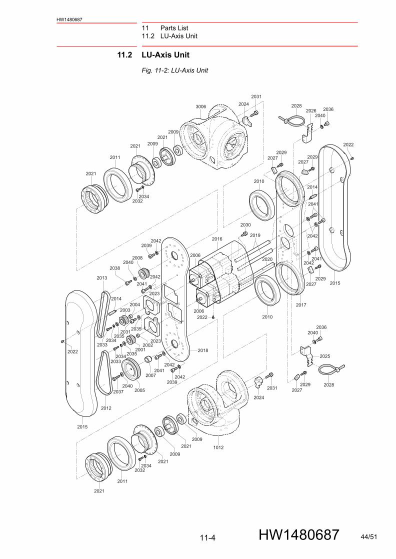
11.2 LU-Axis Unit
Fig. 11-2: LU-Axis Unit
20012033
2033
2035
2035
2034
2034
2003
20352031
2004
2002
2006
2006
2009
2009
20102014
2025
2028
2028
20362040
2041
2042
20412042
20362040
2026
20272027
2027
20272029
2029
20292029
2015
2022
2022
2015
2014
2022
2017
20242031
2031
2024
3006
1012
2019
2020
2018
2016
2010
2011
2021
2021
2021
2021
20212034
2032
2021
2011
2012
2013
2009
2009
200520372040
2040
2007
2008
2041
2030
2042
20412042
2038
20392042
20392042
2023
2023
20342032
44/51

11 Parts List11.2 LU-Axis Unit
11-5
HW1480687
HW1480687
Table 11-2: LU-Axis Unit
No. DWG No. Name Pcs
2001 *HW1401031-1*GHW0483420-A
Pulley 1
2002 HW1401028-1 Collar 1
2003 *HW1401030-1*GHW0483423-A
Pulley 1
2004 HW1401028-1 Collar 1
2005 *HW1401032-1*GHW0483425-A
Pulley 1
2006 SGMAV-A5ANA-YR11(HW0388647-A)
Motor 2
2007 HW1401027-1 Collar 1
2008 HW0483419-A Pulley 1
2009 6000ZZ Bearing 4
2010 6911DDU*NS7* Bearing 2
2011 6913DDU Bearing 2
2012 060S3M309 Belt 1
2013 060S3M327 Belt 1
2014 PSLCG5.5-18 Spacer 8
2015 HW0315902-1 Cover 2
2016 HW0315904-1 Cover 1
2017 HW1300552-1 Plate 1
2018 HW1300866-1 Plate 1
2019 HW0416114-2 Shaft 4
2020 HW0416197-1 Shaft 1
2021 HW0390470-A Speed reducer 2
2022 M3X5 Truss head machine screw (STAINLESS coating)
10
2023 HW0416113-1 M base 2
2024 HW1400596-1 Block 2
2025 HW1401025-1 Support 1
2026 HW1401026-1 Support 1
2027 HW1401029-1 Block 4
2028 T50R Cable tie 4
2029 M3X12 GT-SA bolt 8
2030 M4X10 GT-SA bolt 4
2031 M4X12 GT-SA bolt 8
2032 M3X10 Socket screw 36
2033 M3X12 Socket screw 2
2034 2H-3 Spring washer 38
2035 M4 Washer 4
2036 M4X8 Socket screw 4
2037 M4X16 Socket screw 1
2038 M4X14 Socket screw 1
2039 M4X12 Socket screw 24
2040 2H-4 Spring washer 6
2041 M4X15 Socket screw 10
2042 GT-LH-4 Washer 34
1012 HW0102844-2 S head 1
3006 HW0102844-2 S head 1
45/51

11 Parts List11.3 R-Axis Unit
11-6
HW1480687
HW1480687
11.3 R-Axis Unit
Fig. 11-3: R-Axis Unit
3001
3011
3019
3019
3002
3012
30323035
3026
30303029
3005
3003
3020
3010
3016
3015
30273029
3015
3015
3017
3008
3024
3013
2017
2018
30243034
30283033
3024
3024
3004
3023
30233021
3022
3025
3022
3021
3006
3007
3009
30183031
46/51

11 Parts List11.3 R-Axis Unit
11-7
HW1480687
HW1480687
Table 11-3: R-Axis Unit
No. DWG No. Name Pcs
3001 SGMAV-A5ANA-YR21 (HW0388794-A)
Motor 1
3002 *HW1401031-1*GHW0483420-A
Pulley 1
3003 HW0201354-2 Spacer 1
3004 HW1400595-1 Support 1
3005 HW1401028-1 Collar 1
3006 HW0102844-2 S head 1
3007 HW0483421-A Pulley 1
3008 HW9406285-F Pipe 1
3009 HW9406278-2 Washer 1
3010 HW9406276-1 B cover 1
3011 HW0315900-1 Cover 1
3012 HW0416109-1 M base 1
3013 HW0416110-1 B holder 1
3015 HW0390469-A Speed reducer 1
3016 HW9482970-A Bearing 1
3017 6808ZZ*NS7* Bearing 1
3018 060S3M186 Belt 1
3019 M3X4 Truss head machine screw (STAINLESS coating)
4
3020 6806ZZ Bearing 1
3021 M4X6 Sems pan-head machine screw
3
3022 T50R Cable tie 3
3023 TA1-S8 Clamp 3
3024 M3X10 GT-SA bolt 17
3025 M4X12 GT-SA bolt 2
3026 M3X12 Socket screw 1
3027 M3X10 Socket screw 12
3028 M4X16 Socket screw 6
3029 2H-3 Spring washer 13
3030 M4 Washer 1
3031 M4X10 GT-SA bolt 2
3032 M4X16 GT-SA bolt 2
3033 GT-LH-4 Washer 6
3034 EZ0025B0 Cap 1
3035 M4 Washer 2
2017 HW1300552-1 Plate 1
2018 HW1300866-1 Plate 1
47/51
11 Parts List11.4 Wrist Unit
11-8
HW1480687
HW1480687
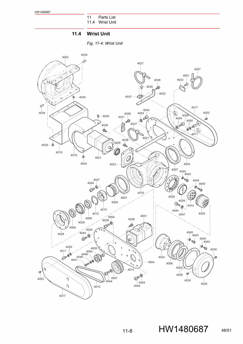
11.4 Wrist Unit
Fig. 11-4: Wrist Unit
4001
4009
40184019
3003
4034
4034
4003
40014006
4012
4006
4028
4029
4031
4029
4029
4028
4028
4010
4013
4017
4017
4011
4011
4050
40334051
4039
4039
4054
4054
4054
4007
4016
40154014
40474044
4044
40444054
40444047
40444047
40444054
40084025
4026
4043
4030
40534030
4030
4030
4030
40304053
40434045
4045
4045
40454040
4042
4024
4020
4007
4021
4022
4023
4038
4038
4037
4035
4027
4027
4027
4038
4002
40414045
4046
4005
4004
4050
4038
4038
48/51
11 Parts List11.4 Wrist Unit
11-9
HW1480687
HW1480687
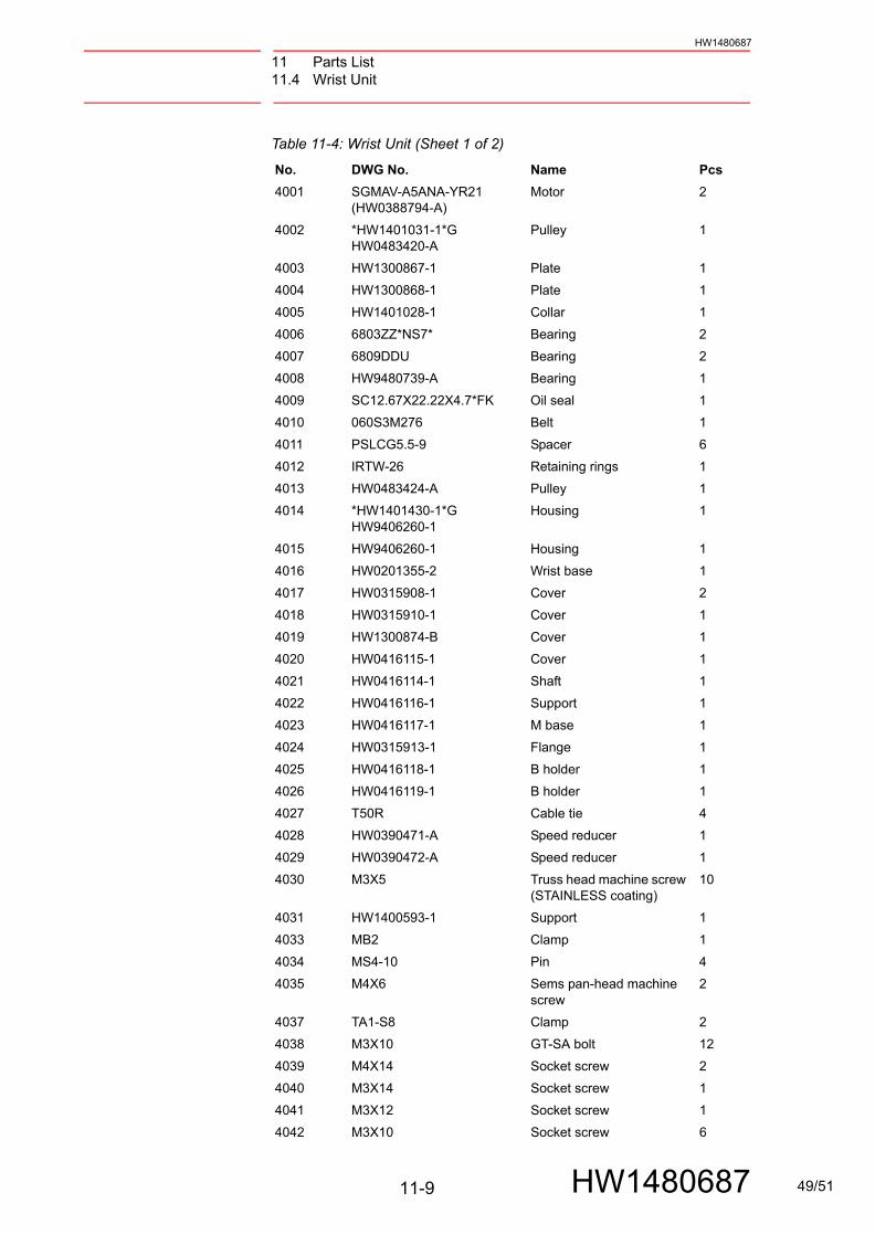
Table 11-4: Wrist Unit (Sheet 1 of 2)
No. DWG No. Name Pcs
4001 SGMAV-A5ANA-YR21 (HW0388794-A)
Motor 2
4002 *HW1401031-1*GHW0483420-A
Pulley 1
4003 HW1300867-1 Plate 1
4004 HW1300868-1 Plate 1
4005 HW1401028-1 Collar 1
4006 6803ZZ*NS7* Bearing 2
4007 6809DDU Bearing 2
4008 HW9480739-A Bearing 1
4009 SC12.67X22.22X4.7*FK Oil seal 1
4010 060S3M276 Belt 1
4011 PSLCG5.5-9 Spacer 6
4012 IRTW-26 Retaining rings 1
4013 HW0483424-A Pulley 1
4014 *HW1401430-1*GHW9406260-1
Housing 1
4015 HW9406260-1 Housing 1
4016 HW0201355-2 Wrist base 1
4017 HW0315908-1 Cover 2
4018 HW0315910-1 Cover 1
4019 HW1300874-B Cover 1
4020 HW0416115-1 Cover 1
4021 HW0416114-1 Shaft 1
4022 HW0416116-1 Support 1
4023 HW0416117-1 M base 1
4024 HW0315913-1 Flange 1
4025 HW0416118-1 B holder 1
4026 HW0416119-1 B holder 1
4027 T50R Cable tie 4
4028 HW0390471-A Speed reducer 1
4029 HW0390472-A Speed reducer 1
4030 M3X5 Truss head machine screw (STAINLESS coating)
10
4031 HW1400593-1 Support 1
4033 MB2 Clamp 1
4034 MS4-10 Pin 4
4035 M4X6 Sems pan-head machine screw
2
4037 TA1-S8 Clamp 2
4038 M3X10 GT-SA bolt 12
4039 M4X14 Socket screw 2
4040 M3X14 Socket screw 1
4041 M3X12 Socket screw 1
4042 M3X10 Socket screw 6
49/51

11 Parts List11.4 Wrist Unit
11-10
HW1480687
HW1480687
4043 M3X8 Socket screw 12
4044 M4X12 Socket screw 31
4045 2H-3 Spring washer 20
4046 M4 Washer 1
4047 2H-4 Spring washer 13
4050 M3 Washer 12
4051 M4X8 Flat head screw 1
4053 M3X5 Hexagon socket button head screw (STAINLESS coating)
6
4054 GT-LH-4 Washer 20
3003 HW0201354-2 Spacer 1
Table 11-4: Wrist Unit (Sheet 2 of 2)
No. DWG No. Name Pcs
50/51

C 2011 YASKAWA ELECTRIC CORPORATIONPublished by YASKAWA
MANUAL NO.
4
January 2020 11-09
HW1480687
MOTOMAN-MHJINSTRUCTIONS
YASKAWA ELECTRIC CORPORATION2-1 Kurosakishiroishi, Yahatanishi-ku, Kitakyushu, 806-0004, JapanPhone: +81-93-645-7703 Fax: +81-93-645-7802http://www.yaskawa.co.jp
YASKAWA AMERICA, INC. (MOTOMAN ROBOTICS DIVISION) 100 Automation Way, Miamisburg, OH 45342, U.S.A.Phone: +1-937-847-6200 Fax: +1-937-847-6277http://www.motoman.com
YASKAWA EUROPE GmbH (ROBOTICS DIVISION)Yaskawastrasse 1, 85391, Allershausen, GermanyPhone: +49-8166-90-100 Fax: +49-8166-90-103http://www.yaskawa.eu.com
YASKAWA NORDIC ABVerkstadsgatan 2, Box 504, SE-385 25 Torsas, SwedenPhone: +46-480-417-800 Fax: +46-486-414-10http://www.yaskawa.se
YASKAWA ELECTRIC (CHINA) CO., LTD.22F, One Corporate Avenue, No.222 Hubin Road, Huangpu District, Shanghai 200021, ChinaPhone: +86-21-5385-2200 Fax: +86-21-5385-3299http://www.yaskawa.com.cn
YASKAWA SHOUGANG ROBOT CO., LTD.No.7 Yongchang North Road, Beijing E&T Development Area, Beijing 100076, ChinaPhone: +86-10-6788-2858 Fax: +86-10-6788-2878http://www.ysr-motoman.cn
YASKAWA ELECTRIC KOREA CORPORATION35F, Three IFC, 10 Gukjegeumyung-ro, Yeongdeungpo-gu, Seoul, 07326, Korea Phone: +82-2-784-7844 Fax: +82-2-784-8495http://www.yaskawa.co.kr
YASKAWA ELECTRIC TAIWAN CORPORATION12F, No.207, Sec. 3, Beishin Rd., Shindian District, New Taipei City 23143, TaiwanPhone: +886-2-8913-1333 Fax: +886-2-8913-1513http://www.yaskawa.com.tw
YASKAWA ASIA PACIFIC PTE. LTD.30A Kallang Place, #06-01, 339213, SingaporePhone: +65-6282-3003 Fax: +65-6289-3003http://www.yaskawa.com.sg
YASKAWA ELECTRIC (THAILAND) CO., LTD.59, 1st-5th Floor, Flourish Building, Soi Ratchadapisek 18, Ratchadapisek Road, Huaykwang,Bangkok 10310, ThailandPhone: +66-2-017-0099 Fax: +66-2-017-0199http://www.yaskawa.co.th
PT. YASKAWA ELECTRIC INDONESIASecure Building-Gedung B Lantai Dasar & Lantai 1 Jl. Raya Protokol Halim Perdanakusuma, Jakarta 13610, IndonesiaPhone: +62-21-2982-6470 Fax: +62-21-2982-6471http://www.yaskawa.co.id
YASKAWA INDIA PRIVATE LIMITED (ROBOTICS DIVISION)#426, Udyog Vihar Phase-IV, Gurgaon, Haryana 122016, IndiaPhone: +91-124-475-8500 Fax: +91-124-475-8542http://www.yaskawaindia.in
For inquiries or after-sales service on this product, contact your local YASKAWA representative as shown below.
51/51