Embed Size (px)
Citation preview

MONITORING CATASTROPHIC FAILURE EVENT IN MILLING PROCESS USING ACOUSTIC EMISSION
HASLAN BIN MOHD YONG
Thesis submitted in fulfilment of the requirements for the award of the degree of
Bachelor of Mechanical Engineering
Faculty of Mechanical Engineering
UNIVERSITY MALAYSIA PAHANG
DECEMBER 2010

iii
SUPERVISOR’S DECLARATION
I hereby declare that I have checked this project and in my opinion, this project is adequate
in terms of scope and quality for the award of the degree of Bachelor of Mechanical
Engineering.
Signature
Name of Supervisor: Madam Miminorazeansuhaila Bt Loman
Position: Lecturer
Date:

v
ACKNOWLEDGEMENTS
By the name of ALLAH, the Most Gracious and Most Merciful
Due to completion of this thesis, I am deeply indebted to my respected supervisor, Miss Miminorazeansuhaila Binti Loman from the Department of Mechanical Engineering for his encouragement, motivation, constructive criticism and beneficial guidance which led me through this project. I would also like to thank Mr. Aziha Bin Abdul Aziz and Miss Sa’adah binti Noor Azmi who continuously guide me during performing the milling research and do the analysis using high resolution microscope.
Deep gratitude goes to multitude of my friends who have contributed their aid in some manner, especially Emir Izwandy Bin Dzulkafli and Mohd Fikri Aziz Bin Mat Lah directly and indirectly to me.
Lastly, I would like to take this opportunity to thank everyone who involved directly or indirectly during this process on completing this research. Only ALLAH S.W.T could bestow all of you with His bless and kindness, handsomely reward for your contributions.
vi
ABSTRACT
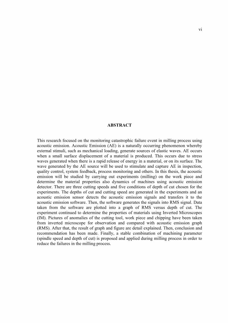
This research focused on the monitoring catastrophic failure event in milling process using acoustic emission. Acoustic Emission (AE) is a naturally occurring phenomenon whereby external stimuli, such as mechanical loading, generate sources of elastic waves. AE occurs when a small surface displacement of a material is produced. This occurs due to stress waves generated when there is a rapid release of energy in a material, or on its surface. The wave generated by the AE source will be used to stimulate and capture AE in inspection, quality control, system feedback, process monitoring and others. In this thesis, the acoustic emission will be studied by carrying out experiments (milling) on the work piece and determine the material properties also dynamics of machines using acoustic emission detector. There are three cutting speeds and five conditions of depth of cut chosen for the experiments. The depths of cut and cutting speed are generated in the experiments and an acoustic emission sensor detects the acoustic emission signals and transfers it to the acoustic emission software. Then, the software generates the signals into RMS signal. Data taken from the software are plotted into a graph of RMS versus depth of cut. The experiment continued to determine the properties of materials using Inverted Microscopes(IM). Pictures of anomalies of the cutting tool, work piece and chipping have been taken from inverted microscope for observation and compared with acoustic emission graph(RMS). After that, the result of graph and figure are detail explained. Then, conclusion and recommendation has been made. Finally, a stable combination of machining parameter (spindle speed and depth of cut) is proposed and applied during milling process in order to reduce the failures in the milling process.

vii
ABSTRAK
Tesis ini difokuskan kepada pemantauan terhadap kegagalan yang berlaku di dalam proses pengisaran dengan menggunakan sinaran akustik. Sinaran akustik (AE) adalah sebuah fenomena yang berlaku secara semulajadi di mana rangsangan luaran, seperti beban mekanikal, menghasilkan sumber gelombang elastik. AE terjadi ketika peralihan permukaan kecil dari material yang dihasilkan. Hal ini terjadi kerana gelombang stres yang terhasil ketika ada pembebasan tenaga yang berterusan dalam suatu material, atau pada permukaannya. Gelombang yang dihasilkan oleh sumber AE dan akan digunakan untuk merangsang dan menangkap AE di dalam pemeriksaan, kawalan kualiti, maklum balas sistem, pemantauan proses dan lain-lain. Dalam tesis ini, sinaran akustik akan dipelajari dengan melakukan eksperimen (pengisaran) pada bahan kerja dan menentukan sifat material dan juga kedinamikan mesin menggunakan pengesan sinaran akustik. Tiga kelajuan pemotongan dan lima kedalaman pemotongan yang dipilih untuk eksperimen. Kedalaman pemotongan dan kelajuan pemotongan yang dihasilkan dalam eksperimen dan sensor sinaran akustik mengesan isyarat sinaran akustik dan memindahkannya ke peranti perisian sinaran akustik. Kemudian, perisian menghasilkan isyarat menjadi isyarat RMS. Data diambil dari perisian diplot ke dalam graf RMS melawan kedalaman pemotongan. Eksperimen dilanjutkan untuk mengetahui sifat-sifat bahan menggunakan Mikroskop Songsang(MS). Gambar anomali dari bahan, alat pemotongan dan cip akan diambil dari mikroskop songsang untuk diamati dan dibandingkan dengan graf sinaran akustik (RMS).Selepas itu, keputusan dan gambar anomali diterangkan secara terperinci. Seterusnya, penutup dan cadangan dibuat. Dan akhirnya, kombinasi parameter mesin yang stabil (halaju spindle dan kedalaman pemotongan) akan diperkenalkan dan dilaksanakan dalam proses milling bagi tujuan mengurangkan kadar kegagalan yang berlaku didalam proses perngisaran.

viii
TABLE OF CONTENTS
CHAPTER TITLE PAGE
TITLE PAGE i
EXAMINERS APPROVAL DOCUMENT ii
SUPERVISOR’S DECLARATION iii
CANDIDATE’S DECLARATION iv
DEDICATION v
ACKNOWLEDGEMENTS vi
ABSTRACT vii
ABSTRAK viii
TABLE OF CONTENT ix
LIST OF TABLES x
LIST OF FIGURES xi
LIST OF ABBREVIATIONS xii
1 INTRODUCTION
1.1 Introduction 1
1.2 Project Background 2

ix
1.3 Problem Statement 3
1.4 Objectives of Research 4
1.5 Scopes of Studies 5
1.6 Overview of Thesis 5
1.7 Project Flow chart 7
2 LITERATURE REVIEW
2.1 Introduction 9
2.2 Application of High-Speed Machining 10
2.3 Acoustic Emission Phenomenon 12
2.3.1 Sources of Acoustic Emission 122.3.2 Wave Propagation 132.3.3 Qualitative Types of Acoustic Emission 13
2.4 Acoustic Emission Technology 15
2.4.1 Sensors 152.4.2 Acoustic Emission System 152.4.3 Acoustic Emission Detection 16
2.5 Parameter in Acoustic Emission Signal 17
2.5.1 Amplitude 172.5.2 Root Mean Square 18
2.6 Type of Cutting Tool 18
2.6.1 Cutting Parameter and Tool Geometry 19
3 METHODOLOGY
3.1 Introduction 23
3.2 Project Design 24
3.2.1 Determine Material, Method and Machining Parameter 25
3.3 Design of Experiment 30
3.3.1 Machining Process 323.3.2 Result Analysis 333.3.3 Data Discussion and Conclusion 33
x
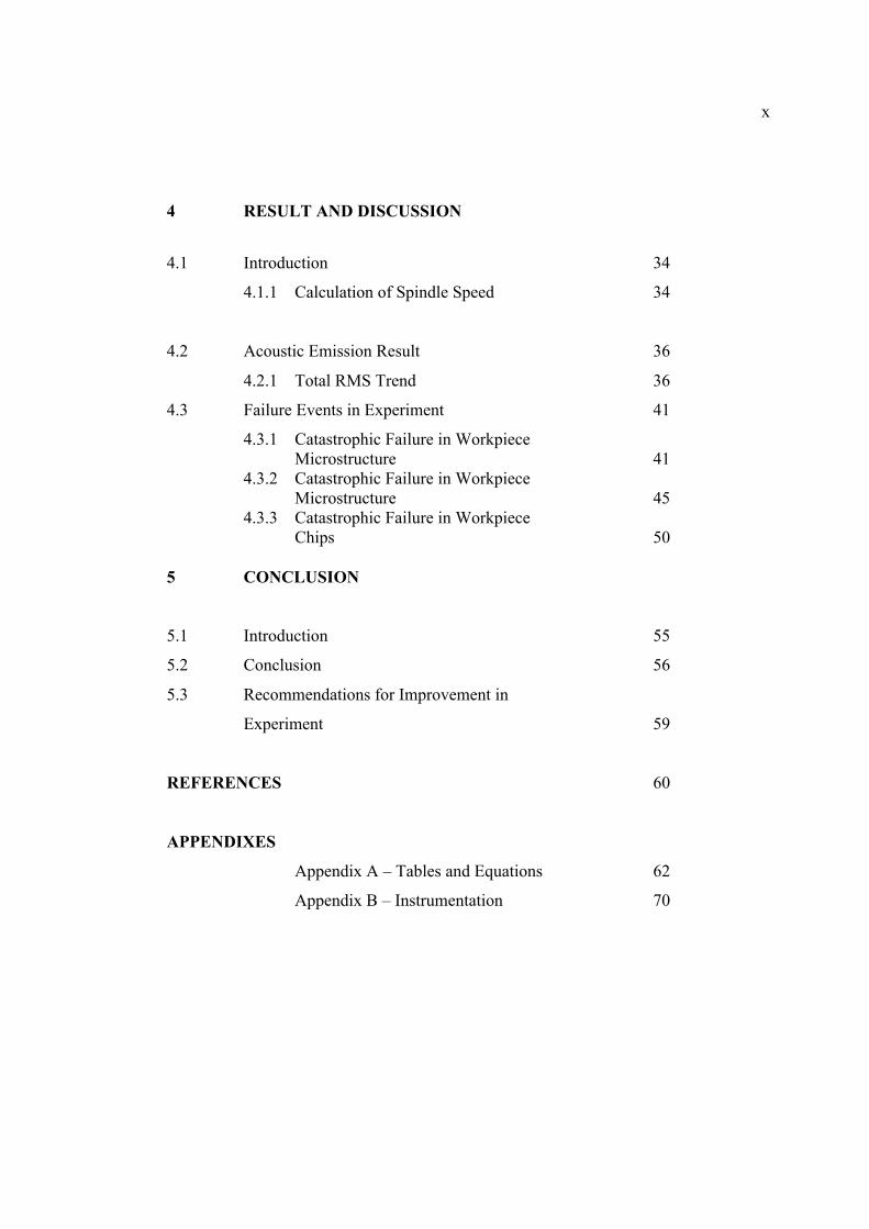
4 RESULT AND DISCUSSION
4.1 Introduction 34
4.1.1 Calculation of Spindle Speed 34
4.2 Acoustic Emission Result 36
4.2.1 Total RMS Trend 36
4.3 Failure Events in Experiment 41
4.3.1 Catastrophic Failure in WorkpieceMicrostructure 41
4.3.2 Catastrophic Failure in Workpiece Microstructure 45
4.3.3 Catastrophic Failure in Workpiece Chips 50
5 CONCLUSION
5.1 Introduction 55
5.2 Conclusion 56
5.3 Recommendations for Improvement in
Experiment 59
REFERENCES 60
APPENDIXES
Appendix A – Tables and Equations 62
Appendix B – Instrumentation 70

xi
LIST OF TABLES
Table No. Title Page
2.1 Cutting speed for HSS and Carbide cutting tool 20
3.1 Properties of 1018 mild steel (low carbon) 25
3.2 Parameter for Milling process 31
4.1 Total RMS value for 2 flutes 37
4.2 Total RMS value for 4 flutes 38
4.3 Total RMS value for 2 and 4 flutes 39
5.1 Ideal setting of machining parameter for 2 flutes 57
5.2 Ideal setting of machining parameter for 4 flutes 58

xii
LIST OF FIGURES
1.1 Project flow chart 8
2.1 Schematic representation of milling process 10
2.2 Attainable speed in machining for various materials 11
2.3a Burst type signal 14
2.3b Continuous type signal 14
2.4a Acoustic Emission sensors 16
2.4b Multichannel data acquisition system 16
2.5 Design Criteria of End mill cutting tool 21
3.1 Procedure flow diagram 23
3.2 Design layout for milling process 24
3.3 1018 mild steel (low carbon) 25
3.4 Slot Cut 26
3.5 AED2000V 27
3.6 Integral premp AE sensor 28
3.7 Grease 28
3.8 AED software 29
Figure No. Title Page

xiii
4.1 Graph of total RMS trend for 2 flutes 37
4.2 Graph of total RMS trend for 4 flutes 38
4.3 Graph of total RMS trend for 2 and 4 flutes 39
4.4 Surface microstructure at 400 RPM (2 flutes) 41
4.5 Surface microstructure at 600 RPM (2 flutes) 42
4.6 Surface microstructure at 800 RPM (2 flutes) 42
4.7 Surface microstructure at 400 RPM (4 flutes) 43
4.8 Surface microstructure at 600 RPM (4 flutes) 43
4.9 Surface microstructure at 800 RPM (4 flutes) 44
4.10 Cutting tool microstructure at 400 RPM (2 flutes) 46
4.11 Cutting tool microstructure at 600 RPM (2 flutes) 46
4.12 Cutting tool microstructure at 800 RPM (2 flutes) 47
4.13 Cutting tool microstructure at 400 RPM (4 flutes) 47
4.14 Cutting tool microstructure at 600 RPM (4 flutes) 48
4.15 Cutting tool microstructure at 800 RPM (4 flutes) 48
4.16 Chip form at 400 RPM (2 flutes) 50
4.17 Chip form at 600 RPM (2 flutes) 51
4.18 Chip form at 800 RPM (2 flutes) 51
4.19 Chip form at 400 RPM (4 flutes) 52
4.20 Chip form at 600 RPM (4 flutes) 52
4.21 Chip form at 800 RPM (4 flutes) 53

xiv
LIST OF ABBREVIATIONS
AE Acoustic Emission
ADC Analog Digital Converter
AISI American Iron and Steel Institute
ASTM American Society for Testing and Materials
BUE Build Up Edge
CS Cutting speed
DB Decibels
DoC Depth of cut
DOE Design of Experiment
HB Brinell hardness
HSM High Speed Machining
HSS High Speed Steel
LAE Lab assistant engineer
NDT Non Destructive Testing
Ni Nickel
RMS Root Mean Square
RPM Rotation per minute, spindle speed
Ti Titanium

CHAPTER 1
INTRODUCTION
1.1 INTRODUCTION
The industrial demands for machining systems to increase process productivity
and quality in milling of critical safety components requires advance investigations of
monitoring techniques. Monitoring and analyzing of failures that happen the milling
process will help researcher predict cutting tool life and breakage in the workpiece. This
thesis is focused on the detection and prediction of the occurrence of process
malfunctions at both of tool and workpiece surface integrity levels using Acoustic
Emission. Acoustic emission (AE) has been employed predominantly for tool condition
monitoring of continuous machining operations (e.g. turning, drilling), but relatively
little attention has been paid to monitor interrupted processes such as milling and
especially to detect the occurrence of possible surface anomalies. (Marinescu and
Axinte, 2008).
The purpose of this thesis is to monitor catastrophic failure event in machining
process (milling) using acoustic emission. The research focused to determine the
failures that will occur in milling process and analyze them using Acoustic Emission
(AE). Additionally, process monitoring is likely to reduce the number of scrap
components via prevention and/or detection of tool and workpiece malfunctions before
significant damaging events occur during the final machining operations.

2
1.2 PROJECT BACKGROUND
In recent years, research in the area of machining process has become very
useful for industries that are considering improving their products and avoiding major
losses in machining. For example, in manufacturing industries, manufacturers usually
focused on the quality and productivity of the product.
In the production lines, problems that usually occur are malfunctioning of the
machine and product defect. To increase the productivity of the product and lessen the
manufacturing costs and times, manufacturing companies and researchers have done a
lot of research in the process malfunctions at both of tool and workpiece. Several
experiments and simulations had been made to decrease this failure event.
Manufactures control cutting speed during running their production. To get a
best cutting speed, related formulas have been created. By using these formulas, some
of product defect can be decrease but it is only occur on material that have low strength
properties like aluminum and steel. Thus, for materials that have high strength
properties, a new method should be created so that manufacturing industries can
manufacture faster and produce high quality of product.
3
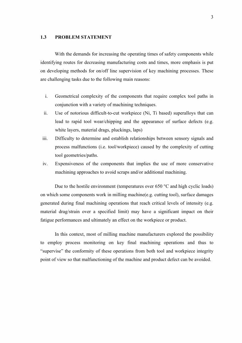
1.3 PROBLEM STATEMENT
With the demands for increasing the operating times of safety components while
identifying routes for decreasing manufacturing costs and times, more emphasis is put
on developing methods for on/off line supervision of key machining processes. These
are challenging tasks due to the following main reasons:
i. Geometrical complexity of the components that require complex tool paths in
conjunction with a variety of machining techniques.
ii. Use of notorious difficult-to-cut workpiece (Ni, Ti based) superalloys that can
lead to rapid tool wear/chipping and the appearance of surface defects (e.g.
white layers, material drags, pluckings, laps)
iii. Difficulty to determine and establish relationships between sensory signals and
process malfunctions (i.e. tool/workpiece) caused by the complexity of cutting
tool geometries/paths.
iv. Expensiveness of the components that implies the use of more conservative
machining approaches to avoid scraps and/or additional machining.
Due to the hostile environment (temperatures over 650 °C and high cyclic loads)
on which some components work in milling machine(e.g. cutting tool), surface damages
generated during final machining operations that reach critical levels of intensity (e.g.
material drag/strain over a specified limit) may have a significant impact on their
fatigue performances and ultimately an effect on the workpiece or product.
In this context, most of milling machine manufacturers explored the possibility
to employ process monitoring on key final machining operations and thus to
“supervise” the conformity of these operations from both tool and workpiece integrity
point of view so that malfunctioning of the machine and product defect can be avoided.
4
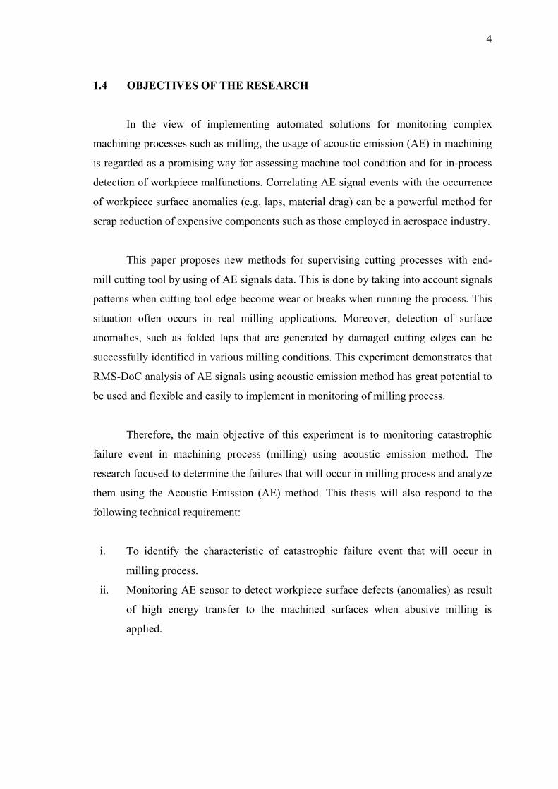
1.4 OBJECTIVES OF THE RESEARCH
In the view of implementing automated solutions for monitoring complex
machining processes such as milling, the usage of acoustic emission (AE) in machining
is regarded as a promising way for assessing machine tool condition and for in-process
detection of workpiece malfunctions. Correlating AE signal events with the occurrence
of workpiece surface anomalies (e.g. laps, material drag) can be a powerful method for
scrap reduction of expensive components such as those employed in aerospace industry.
This paper proposes new methods for supervising cutting processes with end-
mill cutting tool by using of AE signals data. This is done by taking into account signals
patterns when cutting tool edge become wear or breaks when running the process. This
situation often occurs in real milling applications. Moreover, detection of surface
anomalies, such as folded laps that are generated by damaged cutting edges can be
successfully identified in various milling conditions. This experiment demonstrates that
RMS-DoC analysis of AE signals using acoustic emission method has great potential to
be used and flexible and easily to implement in monitoring of milling process.
Therefore, the main objective of this experiment is to monitoring catastrophic
failure event in machining process (milling) using acoustic emission method. The
research focused to determine the failures that will occur in milling process and analyze
them using the Acoustic Emission (AE) method. This thesis will also respond to the
following technical requirement:
i. To identify the characteristic of catastrophic failure event that will occur in
milling process.
ii. Monitoring AE sensor to detect workpiece surface defects (anomalies) as result
of high energy transfer to the machined surfaces when abusive milling is
applied.

5
1.5 SCOPE OF STUDIES
In order to achieve the objectives the following scope of studies are performed:
i. Find out suitable cutting tool for related workpiece (mild steel).
ii. Dimensioning the current workpiece using manual measured.
iii. Conduct Acoustic Emission experiment on milling machine to get the data.
iv. Determine the result that can get from AE sensor and analysis AE data by
considering the total RMS value versus cutting depth graph.
v. Record the anomalies that have occurred relate to the experiment by using high
resolution microscope and analyze it.
vi. Graph RMS-DoC is plotted to determine when the failure occur.
vii. Graph and figure is compared to get the result.
viii. Explanations about the result of graph and figure.
ix. Conclusion and recommendation to be made.
1.6 OVERVIEW OF THE THESIS
This report is divided into six chapters. Chapter one gives the brief the content
and background of the project. The problem statement, objectives and scope of study
are also discussed in this chapter.
In chapter two, the literature review of the study is discussed. This chapter
provided with introduction to Acoustic Emission (EA) method. Starting from the
historical review of EA, Then, we will go deeper into various methods of EA, signal
processing, time-frequency analysis and characteristic or behavior of the failure event
that occur in the experiment. The second part of this literature will review about the
machining process that used. For this thesis, milling process is used as major
contributed process that will cause failure event. This thesis also exposed a little in
milling process such as definition, operation, type of cutting tool and some parameter
that will use and the last part is the catastrophic failure event that will occur in milling
process.

6
For chapter three, methodology of the experiment is reviewed. Flow chart is
shown so that the time required for this thesis is on schedule. After that, the Acoustic
Emission (EA) method and milling process are studied. Then, the thesis explained about
the milling operation that used in this experiment. Some calculations for parameters
given (cutting speed and feed rate) are required to get better result. Finally, the
experiment will be run with supervised by laboratory assistant engineer (LAE). Their
supervision is important due to avoid unnecessary things happen.
In chapter four, the result from the experiment and characteristics of cutting tool
are shown for further analysis. In this chapter, the details of required calculation and
discussion to be determined. Follow by graph analysis to determine root mean square
(RMS) value. The analysis of microstructure also conducted to get the catastrophic
failure event which happened in the workpiece, cutting tool and chip deformation.
Lastly, in chapter five, the conclusion and recommendation are to be made from
the all the chapters that have stated above so that further analysis can be done in the
future.
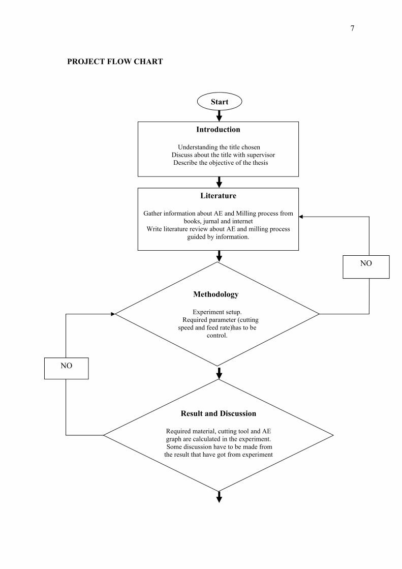
7
PROJECT FLOW CHART
Start
Introduction
Understanding the title chosen Discuss about the title with supervisor
Describe the objective of the thesis
Literature
Gather information about AE and Milling process from books, jurnal and internet
Write literature review about AE and milling process guided by information.
Methodology
Experiment setup. Required parameter (cutting speed and feed rate)has to be
control.
Result and Discussion
Required material, cutting tool and AE graph are calculated in the experiment. Some discussion have to be made from
the result that have got from experiment
NO
NO

8
Figure 1.1: Project flow chart
Summary and Conclusion
Conclusion will be made. Improvement and recommendation are required so that can do further study.
Complete report and presentation
Finish report with full content prepare for presentation
End

CHAPTER 2
LITERATURE REVIEW
2.1 INTRODUCTION
In these recent years, metal cutting technology has growth rapidly and become
one of important aspect in manufacturing industry especially for the aerospace industry
and also in producing high precision part. In modern cutting technology, higher
availability with more flexibility cutting machine will be choose as priority in
manufacturing. Milling is the most important and widely useful operation process for
material removal compared to turning, grinding and drilling.
Milling can be defined as machining process in which metal is removed by a
rotating multiple-tooth cutting tool with each tooth removes small amount of metal in
each revolution of the spindle. Because both workpiece and cutting tool can be moved
in more than one direction at the same time, surfaces having almost any orientation can
be machined. In accordance to (Denis R. Cormier, 2005), milling is metal removal
machining process for generate machined surface by removing a predetermined amount
of material progressively from the specimen. In milling process, a milling cutting tool is
held in a rotating spindle, while the workpiece clamped in the table is linearly moved
toward the cutting tool (Altintas, 2000). A schematic representation of milling process
is shown in Figure 2.1.

10
Figure 2.1: Schematic representation of milling process
Source: Altintas (2000)
2.2 APPLICATION OF HIGH-SPEED MACHINING
The term High-Speed Machining (HSM) commonly refers to end milling at high
rotational speeds and high surface feeds. HSM has been applied to a wide range of
metallic and non-metallic materials, including the production of components with
specific surface topography requirements and machining of materials with hardness of
50 HB and above. With regard to attainable cutting speeds, it is suggested that the term
HSM is standing for operating at cutting speeds significantly higher than those typically
utilized for a particular material. The figure below indicated the attainable speeds in the
machining of various materials.
But in practical definition, HSM is not simply high cutting speed. It should be
regarded as a process where the operations are performed with very specific methods
and production equipment. HSM is also not necessarily high spindle speed machining.
Many HSM applications are performed with moderate spindle speeds and large sized
cutting tools.

11
Figure 2.2: Attainable speed in machining for various materials
There are several factors for choosing High-speed Machining (HSM). The ever-
increasing competition on the marketplace is setting new standards all the time. The
demands on time and cost efficiency are getting higher and higher, forcing the
development of new processes and production methods to take place. HSM usage will
guaranteed in time saving nonetheless provide much in product quality and quantity
compared to conventional milling operation. The other factor is the development of
new; more difficult to machine materials which has underlined the necessity to find new
machining solutions. The die and mold industry mainly has to face the problem of
machining highly hardened tool steels, from roughing to finishing.
With regard to this problem, HSM has technically proved a better performance
in finishing in hardened steel with high speeds and feeds, often with 4-6 times
conventional cutting data. On the other hand, high-speed machining is a potentially
unstable system, where the forces generated by the cutting process are coupled to the
dynamic behavior (stiffness, damping, and inertia) of the machine structure, tool, and
workpiece (Sims, 2004). These behaviors will generate a failure to workpiece several
and also cutting tool after in the period of being used. Therefore, new software
experiments have been developing due to avoid more failure from occurs. One of
promising way to detect a failure is using Acoustic Emission Testing (AET) method.

12
2.3 ACOUSTIC EMISSION PHENOMENON
Understanding the physical nature of acoustic emission in different materials is
one of the important parts in the development of the acoustic emission technology. The
success and the depth of the technology capabilities depend on the ability to determine
the interconnection between characteristics of acoustic emission and sources it
generated. However, establishing such interconnection for different materials and
structures is a real scientific and technological challenge to machinists and researchers.
2.3.1 Sources of Acoustic Emission
The main purpose of acoustic emission examinations in industrial applications
today, are detection, location and assessment of flaws in structures made of metal,
concrete or composites. In these materials, fracture development in form of crack
propagation is a primary source of acoustic emission. Elementary crack jumps under
static or dynamic loads are followed by a rapid release of energy. A part of this energy
is released in form of stress waves as a result of fast redistribution of a stress field at the
crack top. The stress waves generated are elastic waves mostly but inelastic waves can
be generated also when stresses exceed yield limit. This occurs, for example, at the
plastic zone of a crack developing in a ductile metal. Other primary sources of acoustic
emission in materials that undergo fracture are:
i. Plastic deformation development and fracturing of hard inclusions in metals;
ii. Fiber breakage, matrix cracking and delamination in composites;
iii. Aggregate fracture, voids closure and etc. in concrete.
Acoustic emission equipment is capable of detecting and analyzing acoustic
emission sources of non-material origin, for instance, mechanical sources of friction,
knocks, and leaks and so on. There are multiple applications in which acoustic emission
technology is used for revealing leaks, machinery health monitoring, detection of
dynamic stress events in structures and other using these capabilities.