Embed Size (px)
Citation preview

M. Krishna Kumar MM/M4/LU10/V1/2004 1
Overview
Each processor in the 80x86 family has a corresponding coprocessor with which it is compatibleMath Coprocessor is known as NPX,NDP,FUP.Numeric processor extension (NPX),Numeric data processor (NDP),
Floating point unit (FUP).

M. Krishna Kumar MM/M4/LU10/V1/2004 2
Processors1. 8086 & 80882. 802863. 80386DX4. 80386SX5. 80486DX6. 80486SX
Coprocessors1. 80872. 80287,80287XL3. 80287,80387DX4. 80387SX5. It is Inbuilt6. 80487SX
Compatible Processor and Coprocessor

M. Krishna Kumar MM/M4/LU10/V1/2004 3
Pin Diagram of 8087
20GND
1918
CLK
NC
NC 1716
GNDAD14
AD13
AD12
AD11
AD10
AD9AD8AD7
AD6
AD5
AD4
AD3
AD2
AD1AD0
1514
13
1211
12345678
910
RESET
READY
BUSY
QS1
VccAD15
A16/S3
A17/S4
A18/S5
_____
BHE/S7
A19/S6
________
RQ/GT1INT_______
RQ/GT0
NC
NC _
S2__
S1
QS0
21
2223
242526272829
30
403938373635343332
31
__
S0
8087
NPX
(A14)
(A13)(A12)(A11)(A10)(A9)(A8)

M. Krishna Kumar MM/M4/LU10/V1/2004 4
Architecture of 8087
Control UnitExecution Unit

M. Krishna Kumar MM/M4/LU10/V1/2004 5
8-register stack, each has 80 bits
079Vcc
+5V
0
4 MSB of operand address 0
16 LSB of operand address
Floating point arithmetic module
Status Register 16 bit
Control Register
16 LBS of instruction address
11 LSB of op code04MSB inst address
Bus tracking control logic, instruction queue
Ready
Reset
Busy
CLKINT
QS1-QS0
A19/S6 __ A16/S3
AD15 - AD0
to
____ ____
RQ/GT1
____ ____
RQ/GT0
_____
BHE/S7
vss
TAG
TAG 7
TAG register
Block Diagram of 8087

M. Krishna Kumar MM/M4/LU10/V1/2004 6
Control word
Control Unit
Status word
8 Register StackTagword
0
7
Exceptionpointer
Addressing bus tracking
Data
buffer
ExponentModule
Operand queue
Micro control unit
Programmable shifter
Arithmetic module
temporary register
Numeric execution unit
Address
Status
Data
interface
80 Bits
16
16
16
64
68
Exponent bus Fraction bus
Block Diagram of 8087

M. Krishna Kumar MM/M4/LU10/V1/2004 7
Control Unit
Control unit: To synchronize the operation of the coprocessor and the processor.This unit has a Control word and Status word and Data BufferIf instruction is an ESCape (coprocessor) instruction, the coprocessor executes it, if not the microprocessor executes.

M. Krishna Kumar MM/M4/LU10/V1/2004 8
Status Register (cont..)
• C3-C0 Condition code bits• TOP Top-of-stack (ST)• ES Error summary• PE Precision error• UE Under flow error• OE Overflow error• ZE Zero error• DE Denormalized error• IE Invalid error• B Busy bit
B C3 ST C2 C1 C0 ES PE UE OE ZE DE IE
015

M. Krishna Kumar MM/M4/LU10/V1/2004 9
Status register reflects the over all operation of the coprocessor.B-Busy bit indicates that coprocessor is busy executing a task. Busy can be tested by examining the status or by using the FWAIT instruction. Newer coprocessor automatically synchronize with the microprocessor, so busy flag need not be tested before performing additional coprocessor tasks.C3-C0 Condition code bits indicates conditions about the coprocessor.
Status Register (cont..)

M. Krishna Kumar MM/M4/LU10/V1/2004 10
TOP- Top of the stack (ST) bit indicates the current register address as the top of the stack.ES-Error summary bit is set if any unmasked error bit (PE, UE, OE, ZE, DE, or IE) is set. In the 8087 the error summary is also caused a coprocessor interrupt. PE- Precision error indicates that the result or operand executes selected precision.UE-Under flow error indicates the result is too large to be represent with the current precision selected by the control word.
Status Register (cont..)

M. Krishna Kumar MM/M4/LU10/V1/2004 11
OE-Over flow error indicates a result that is too large to be represented. If this error is masked, the coprocessor generates infinity for an overflow error.ZE-A Zero error indicates the divisor was zero while the dividend is a non-infinity or non-zero number.DE-Denormalized error indicates at least one of the operand is denormalized.IE-Invalid error indicates a stack overflow or underflow, indeterminate from (0/0,0,-0, etc) or the use of a NAN as an operand. This flag indicates error such as those produced by taking the square root of a negative number.
Status Register (contd..)

M. Krishna Kumar MM/M4/LU10/V1/2004 12
Control Register
Control register selects precision, rounding control, infinity control.It also masks an unmasks the exception bits that correspond to the rightmost Six bits of status register.Instruction FLDCW is used to load the value into the control register.

M. Krishna Kumar MM/M4/LU10/V1/2004 13
Control Register
DM IMZMOMUMPMPCRCIC
015
• IC Infinity control• RC Rounding control• PC Precision control• PM Precision control• UM Underflow mask• OM Overflow mask• ZM Division by zero mask• DM Denormalized operand mask• IM Invalid operand mask

M. Krishna Kumar MM/M4/LU10/V1/2004 14
IC –Infinity control selects either affine or projective infinity. Affine allows positive and negative infinity, while projective assumes infinity is unsigned.RC –Rounding control determines the type of rounding.
INFINITY CONTROL0 = Projective1 = Affine
ROUNDING CONTROL00=Round to nearest or even01=Round down towards minus infinity10=Round up towards plus infinity11=Chop or truncate towards zero
Control Register (cont..)
M. Krishna Kumar MM/M4/LU10/V1/2004 15
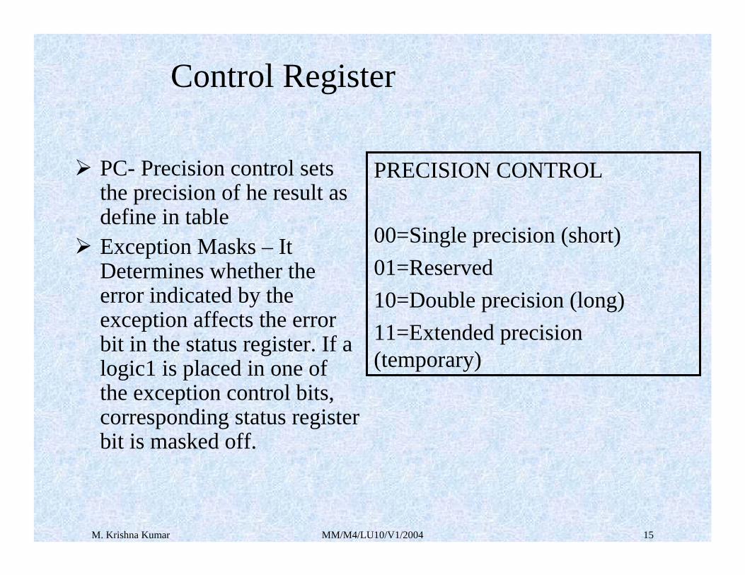
PC- Precision control sets the precision of he result as define in tableException Masks – It Determines whether the error indicated by the exception affects the error bit in the status register. If a logic1 is placed in one of the exception control bits, corresponding status register bit is masked off.
PRECISION CONTROL
00=Single precision (short)01=Reserved10=Double precision (long)11=Extended precision (temporary)
Control Register

M. Krishna Kumar MM/M4/LU10/V1/2004 16
Numeric Execution Unit
This performs all operations that access and manipulate the numeric data in the coprocessor’s registers.Numeric registers in NUE are 80 bits wide.NUE is able to perform arithmetic, logical and transcendental operations as well as supply a small number of mathematical constants from its on-chip ROM.Numeric data is routed into two parts ways a 64 bit mantissa bus and
a 16 bit sign/exponent bus.

M. Krishna Kumar MM/M4/LU10/V1/2004 17
Circuit Connection for 8086 – 8087 (cont.)
8086 CPU
8087
8086
BUS INTER-FACINGCOMPO-NENTS
INTR
CLK____ ____
RQ/GT1
QS0 QS1
_______
TEST
BUSYQS0 QS1____ _____
RQ/GT0
CLK
INT
CLK
8284A
CLICK
GENERATOR
8259A
PIC
INT
IRn
____ _____
RQ/GT1
Multi
master System
bus
Multi
master local
bus
M. Krishna Kumar MM/M4/LU10/V1/2004 18
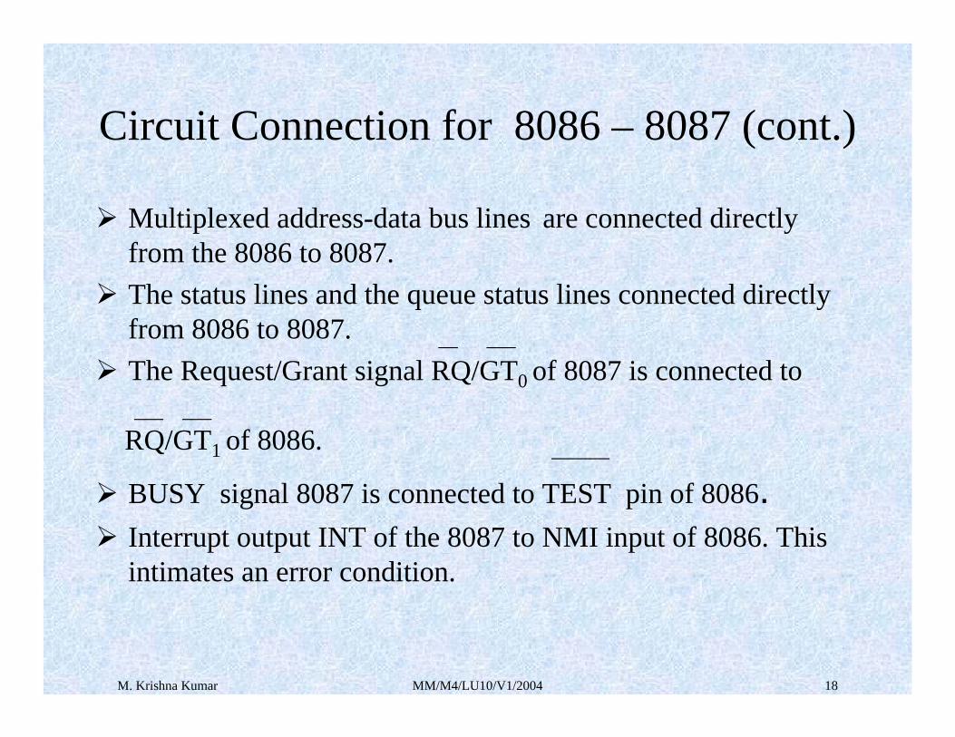
Multiplexed address-data bus lines are connected directly from the 8086 to 8087. The status lines and the queue status lines connected directly from 8086 to 8087. __ ___
The Request/Grant signal RQ/GT0 of 8087 is connected to ___ ___
RQ/GT1 of 8086. ______
BUSY signal 8087 is connected to TEST pin of 8086.Interrupt output INT of the 8087 to NMI input of 8086. This intimates an error condition.
Circuit Connection for 8086 – 8087 (cont.)

M. Krishna Kumar MM/M4/LU10/V1/2004 19
The main purpose of the circuitry between the INT output of 8087 and the NMI input is to make sure that an NMI signal is not present upon reset, to make it possible to mask NMI input and to make it possible for other devices to cause an NMI interrupt.BHE pin is connected to the system BHE line to enable the upper bank of memory.The RQ/GT1 input is available so that another coprocessor such as 8089 I/O processor can be connected and function in parallel with the 8087.
Circuit Connection for 8086 – 8087 (cont.)
M. Krishna Kumar MM/M4/LU10/V1/2004 20
One type of Cooperation between the two processors that you need to know about it is how the 8087 transfers data between memory and its internal registers.When 8086 reads an 8087 instruction that needs data from memory or wants to send data to memory, the 8086 sends out the memory address code in the instruction and sends out the appropriate memory read or memory write signal to transfer a word of data.
Circuit Connection for 8086 – 8087 (cont.)
M. Krishna Kumar MM/M4/LU10/V1/2004 21
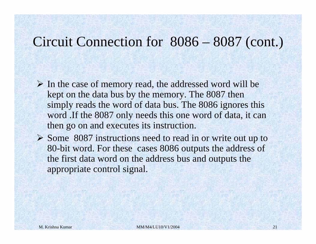
In the case of memory read, the addressed word will be kept on the data bus by the memory. The 8087 then simply reads the word of data bus. The 8086 ignores this word .If the 8087 only needs this one word of data, it can then go on and executes its instruction.Some 8087 instructions need to read in or write out up to 80-bit word. For these cases 8086 outputs the address of the first data word on the address bus and outputs the appropriate control signal.
Circuit Connection for 8086 – 8087 (cont.)

M. Krishna Kumar MM/M4/LU10/V1/2004 22
The 8087 reads the data word on the data bus by memory or writes a data word to memory on the data bus. The 8087 grabs the 20-bit physical address that was output by the 8086.To transfer additional words it needs to/from memory, the 8087 then takes over the buses from 8086.To take over the bus, the 8087 sends out a low-going pulse on ___ ____
RQ/GT0 pin. The 8086 responds to this by sending another low____ ____
going pulse back to the RQ/GT0 pin of 8087 and by floating its buses.
Circuit Connection for 8086 – 8087 (cont.)

M. Krishna Kumar MM/M4/LU10/V1/2004 23
The 8087 then increments the address it grabbed during the first transfer and outputs the incremented address on the address bus. When the 8087 output a memory read or memory write signal, another data word will be transferred to or from the 8087.The 8087 continues the process until it has transferred all the data words required by the instruction to/from memory.
Circuit Connection for 8086 – 8087 (cont.)

M. Krishna Kumar MM/M4/LU10/V1/2004 24
When the 8087 is using the buses for its data transfer, it ____ ___
sends another low-going pulse out on its RQ/ GT0 pin to8086 to know it can have the buses back again.
The next type of the synchronization between the host processor and the coprocessor is that required to make sure the8086 hast does not attempt to execute the next instruction before the 8087 has completed an instruction.
Circuit Connection for 8086 – 8087 (cont.)

M. Krishna Kumar MM/M4/LU10/V1/2004 25
Taking one situation, in the case where the 8086 needs the data produced by the execution of an 8087 instruction to carry out its next instruction. In the instruction sequence for example the 8087 must complete the FSTSW STATUS instruction before the 8086 will have the data it needs to execute the
MOV AX , STATUS instruction.Without some mechanism to make the 8086 wait until the 8087 completes the FSTSW instruction, the 8086 will go on and execute the MOV AX , STATUS with erroneous data .We solve this problem by connecting the 8087 BUSY output to the TEST pin of the 8086 and putting on the WAIT instruction in the program.
Circuit Connection for 8086 – 8087 (cont.)

M. Krishna Kumar MM/M4/LU10/V1/2004 26
While 8087 is executing an instruction it asserts its BUSY pin high. When it is finished with an instruction, the 8087 will drop its BUSY pin low. Since the BUSY pin from 8087 is connected to the TEST pin 8086 the processor can check its pin of 8087 whether it finished it instruction or not.You place the 8086 WAIT instruction in your program after the 8087 FSTSW instruction .When 8086 executes the WAIT instruction it enters an internal loop where it repeatedly checks the logic level on the TEST input. The 8086 will stay in this loop until it finds the TEST input asserted low, indicating the 8087 has completed its instruction. The 8086 will then exit theinternal loop, fetch and execute the next instruction.
Circuit Connection for 8086 – 8087 (cont.)

M. Krishna Kumar MM/M4/LU10/V1/2004 27
FSTSW STATUS ;copy 8087 status word to memoryMOV AX, STATUS ;copy status word to AX to check
; bits
( a )
In this set of instructions we are not using WAIT instruction. Due to this the flow of execution of command will takes place continuously even though the previous instruction had not finished it’s completion of its work .so we may lost data .
Example (cont..)

M. Krishna Kumar MM/M4/LU10/V1/2004 28
FSTSW STATUS ;copy 8087 status word to memoryFWAIT ;wait for 8087 to finish before-
; doing next 8086 instructionMOV AX,STATUS ;copy status word to AX to check
; bits
( b )
In this code we are adding up of FWAIT instruction so that it will stop the execution of the command until the above instruction is finishes it’s work .so that you are not loosing data and after that you will allow to continue the execution of instructions.
Example (cont..)

M. Krishna Kumar MM/M4/LU10/V1/2004 29
Another case where you need synchronization of the processor and the coprocessor is the case where a program has several 8087 instructions in sequence. The 8087 are executed only one instruction at a time so you have to make sure that 8087 has completed one instruction before you allow the 8086 to fetch the next 8087 instruction from memory. ________Here again you use the BUSY-TEST connection and the FWAIT instruction to solve the problem. If you are hand coding, you can just put the 8086 WAIT(FWAIT) instruction after each instruction to make sure that instruction is completed before going on to next.
Circuit Connection for 8086 – 8087 (cont.)

M. Krishna Kumar MM/M4/LU10/V1/2004 30
If you are using the assembler which accepts 8087 mnemonics, the assembler will automatically insert the 8-bit code for the WAIT instruction ,10011011 binary (9BH), as the first byte of the code for 8087 instruction.
Circuit Connection for 8086 – 8087
M. Krishna Kumar MM/M4/LU10/V1/2004 31
Interfacing ( cont..)
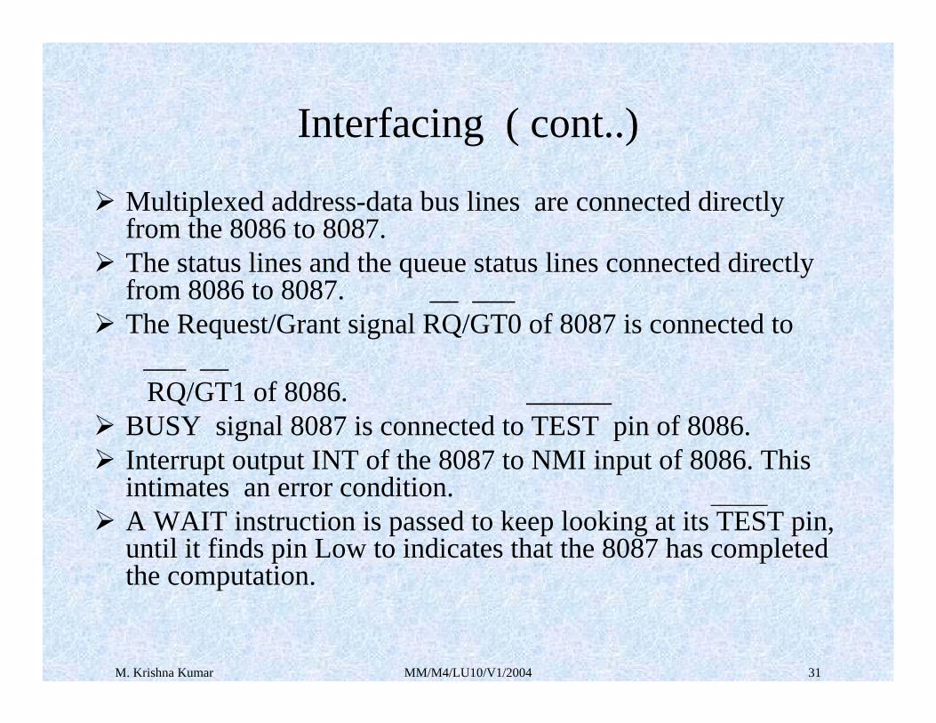
Multiplexed address-data bus lines are connected directly from the 8086 to 8087. The status lines and the queue status lines connected directly from 8086 to 8087. __ ___ The Request/Grant signal RQ/GT0 of 8087 is connected to
___ __ RQ/GT1 of 8086. ______
BUSY signal 8087 is connected to TEST pin of 8086.Interrupt output INT of the 8087 to NMI input of 8086. This intimates an error condition. ______A WAIT instruction is passed to keep looking at its TEST pin, until it finds pin Low to indicates that the 8087 has completed the computation.

M. Krishna Kumar MM/M4/LU10/V1/2004 32
SYNCHRONIZATION must be established between the processor and coprocessor in two situations.
a) The execution of an ESC instruction that require the participation of the NUE must not be initiated if the NUE has not completed the execution of the previous instruction.
b) When a processor instruction accesses a memory location that is an operand of a previous coprocessor instruction .In this case CPU must synchronize with NPX to ensure that it has completed its instruction.
Processor WAIT instruction is provided.
Interfacing