Embed Size (px)
Citation preview

Modificarea suprafetelor implantabile, in vederea cresterii bioperformantelor.
Modificarea suprafetelor metalice implantabile cuacoperiri biomimetice, puncte forte si puncte slabe.
I. Demetrescu
Curs POSDRU
University University PolitehnicaPolitehnica of Bucharest, of Bucharest, ROMANIAROMANIAFaculty of Applied Chemistry and Materials ScienceFaculty of Applied Chemistry and Materials Science

Motivatie si suport
• Motivatie : necesitatea de a imbunatati biomaterialele implantabile in contextul dezvoltariiacoperirilor de suprafata
• Suport : Proiecte si colaborari:• C.N.C.S.I.S.TIPA. „Obtinerea si caracterizarea de noi micro si nanostructuri compozite cu utilizare in
ingineria tisulara”• Elaborarea si testarea in vitro si in vivo a unor elemente de protezare pentru ortopedie, realizate din
noi biomateriale romanesti • Bilaterala Franta Brincusi «Couches minces d'oxyde d'aluminium et d'oxyde de titane pour
différentes applications technologiques et biomédicales• Proiect CEEX Micro si nanostructuri obtinute prin bioactivare chimica si electrochimica cu aplicatii in
medicina regenerativa• Proiect PN2 IDEI Studii exploratorii asupra mecanismului de formare si inducere de noi proprietati
unor electrozi modificati cu forme structurale TiO2 nanotuburi / nanoparticule si compozite polimerice
• Proiect PN2 IDEI complexe PCCE Noi concepte si strategii pentru dezvoltarea cunoasterii unor
noi structuri biocompatibile in bioinginerie

BIOMIMETICS:
{Derived from the Greek ‘bios’, meaning ‘life’, and ‘mimesis’, meaning ‘to imitate’.}
•There are quite a number of terms such as bionics, biomimetics, biognosis, biomimicry, or even 'bionical creativity engineering' that refer to more or less the same thing: the application of methods and systems found in nature to the study and design of engineering systems and modern technology.
•A relatively new entry in this list is 'nanomimetics', an area of biomimetic nanotechnology that tries to duplicate what nature has been doing for billions of years on this planet - creating and manipulating complex nanoscale structures.
•Nanoscientists and nanotechnology researchers use the terms 'self-assembly' and 'bottom-up fabrication' in their efforts to copy the best nanotechnologist around - Mother Nature.

Materials become insensitive to flaws at nanoscale: Lessons from nature

Mineralized structure of tooth. (A) Schematic drawing showing the enamel and dentin regions; (B) SEM micrograph of enamel and (C) SEM micrograph of dentin, showing the tubular morphology, surrounded by dense peritubular dentin – the longitudinal cut along the tubules is seen in the inset image.

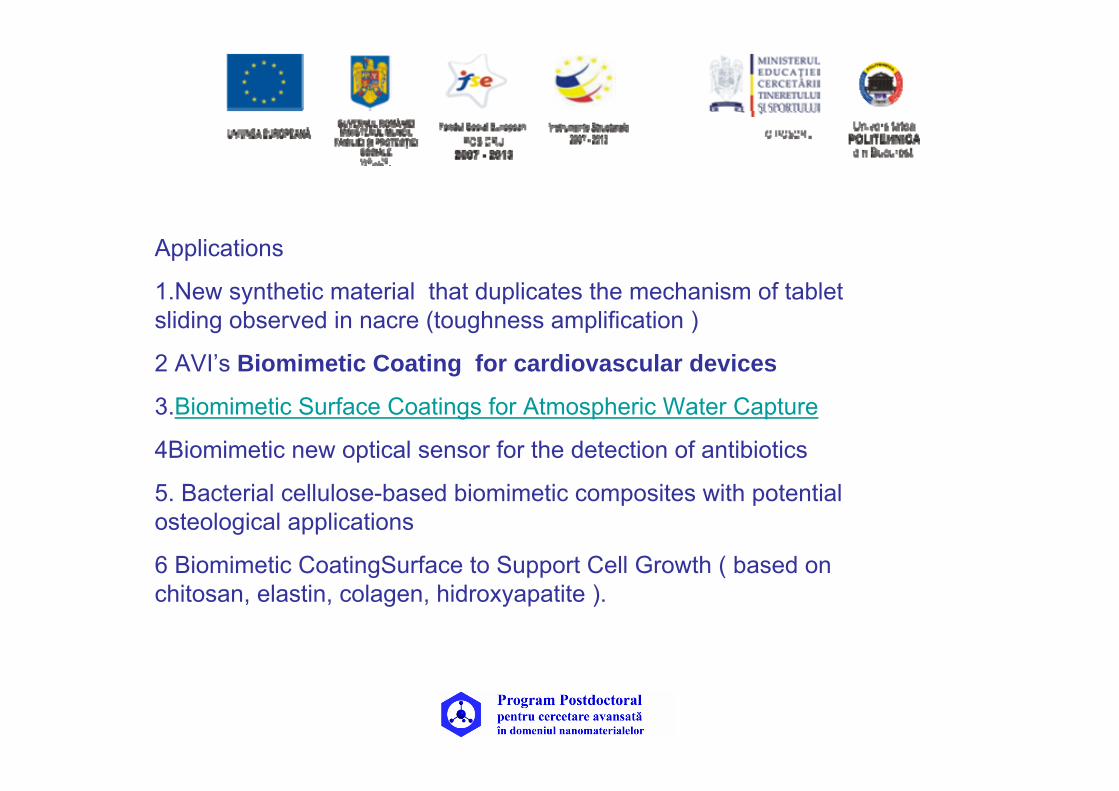
Applications
1.New synthetic material that duplicates the mechanism of tablet sliding observed in nacre (toughness amplification )
2 AVI’s Biomimetic Coating for cardiovascular devices
3.Biomimetic Surface Coatings for Atmospheric Water Capture
4Biomimetic new optical sensor for the detection of antibiotics
5. Bacterial cellulose-based biomimetic composites with potential osteological applications
6 Biomimetic CoatingSurface to Support Cell Growth ( based on chitosan, elastin, colagen, hidroxyapatite ).

Mineralized structures in nature: Examples and inspirations for the design of new composite materials and biomaterials Composites Science and Technology vol 70, 13, 2010, Pag 1777-1788
(A) The general structure of bone, showing its hierarchical organization; (B) fracture surface of a bovine cortical bone revealing a lamellar morphology.
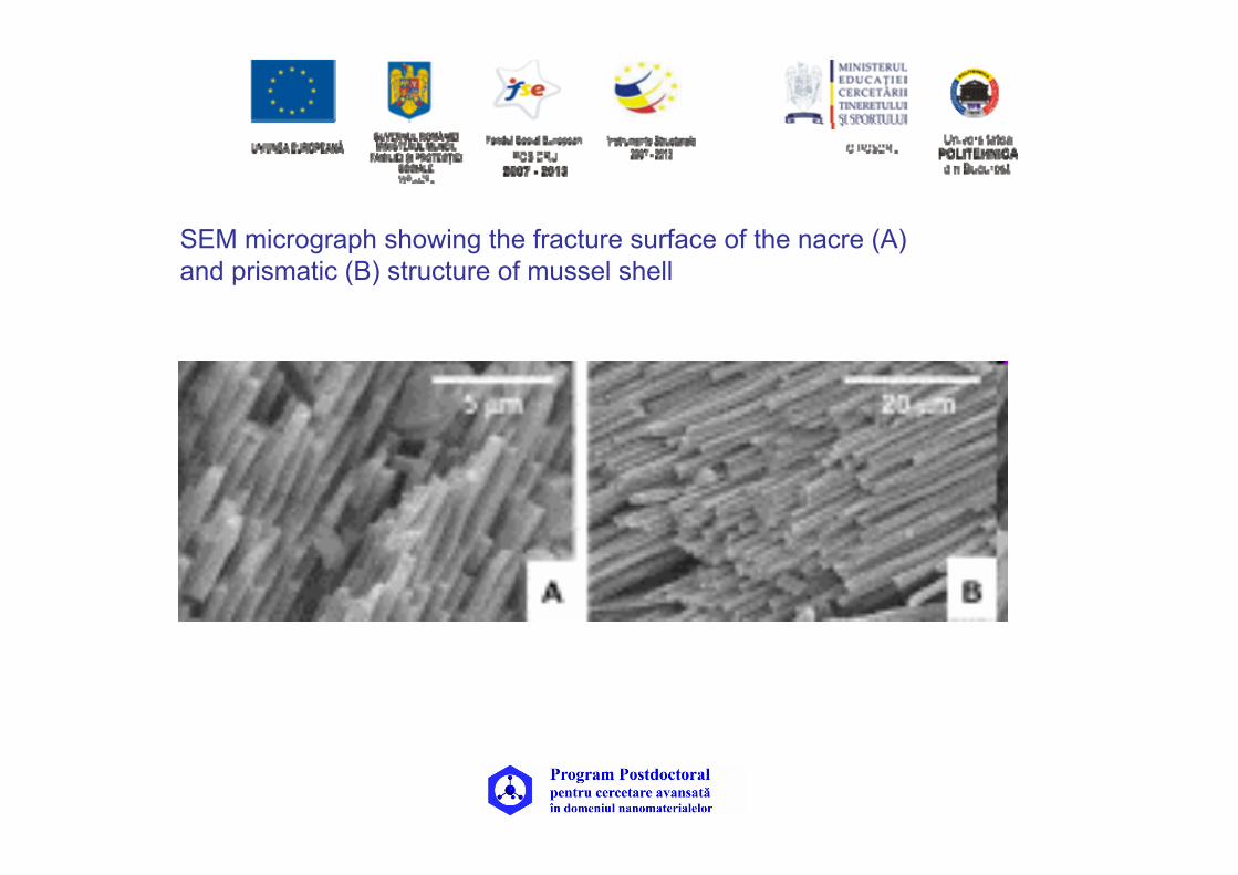
SEM micrograph showing the fracture surface of the nacre (A) and prismatic (B) structure of mussel shell

Compressive and ultimate tensile strengths of nacre under different
loading direction
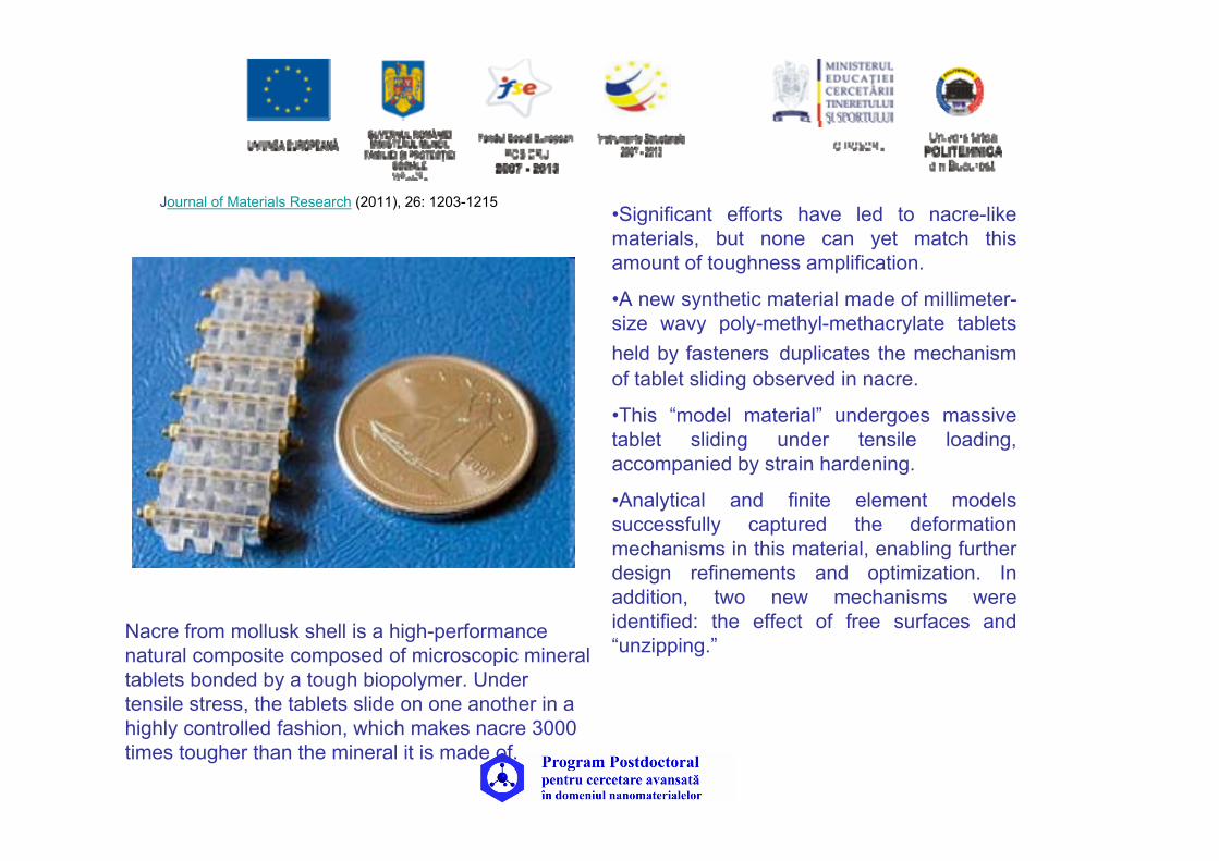
Journal of Materials Research (2011), 26: 1203-1215 •Significant efforts have led to nacre-like materials, but none can yet match this amount of toughness amplification.
•A new synthetic material made of millimeter-size wavy poly-methyl-methacrylate tablets held by fasteners duplicates the mechanism of tablet sliding observed in nacre.
•This “model material” undergoes massive tablet sliding under tensile loading, accompanied by strain hardening.
•Analytical and finite element models successfully captured the deformation mechanisms in this material, enabling further design refinements and optimization. In addition, two new mechanisms were identified: the effect of free surfaces and “unzipping.”
Nacre from mollusk shell is a high-performance natural composite composed of microscopic mineral tablets bonded by a tough biopolymer. Under tensile stress, the tablets slide on one another in a highly controlled fashion, which makes nacre 3000 times tougher than the mineral it is made of.

AVI’s Biomimetic Coating for cardiovascular devices
was designed by polymer scientists at Utah and clinical immunologists at Uppsala.The coating is inspired by the body's natural healing mechanisms and the immune system's ability to recognize "self" from "non-self".
The design incorporates elements that prevent the inflammatory processes that lead to restenosis, while still providing a favorable surface for healing and regeneration of the endothelium; coating has two parts. One is from End Group Activated Polymer and transforms traditional device materials into biocompatible and thromboresistant surfaces.
The second part is a protein called factor H, which interrupts the inflammatory processes that lead to restenosis. Unlike restenosis after stent implantation, restenosis post angioplasty is due largely to elastic recoil with only a small contribution from neointima proliferation.
Electron microscopy image of a coronary stent surface coated with AVI's EGAP and Factor H.
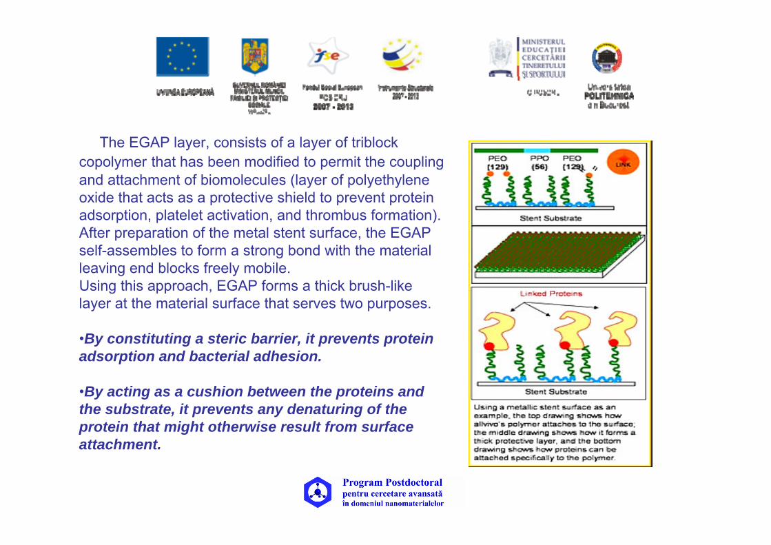
The EGAP layer, consists of a layer of triblock copolymer that has been modified to permit the coupling and attachment of biomolecules (layer of polyethylene oxide that acts as a protective shield to prevent protein adsorption, platelet activation, and thrombus formation). After preparation of the metal stent surface, the EGAP self-assembles to form a strong bond with the material leaving end blocks freely mobile. Using this approach, EGAP forms a thick brush-like layer at the material surface that serves two purposes.
•By constituting a steric barrier, it prevents protein adsorption and bacterial adhesion.
•By acting as a cushion between the proteins and the substrate, it prevents any denaturing of the protein that might otherwise result from surface attachment.

Factor Han important protein that regulates complement activation
This regulation occurs by multiple mechanismswhich include disruption of C3 convertase formation and acceleration of its decay. Factor H also acts as a cofactor to factor I in the degradation of C3b, and competes with factor B for binding to C3b. Factor H can be produced recombinantly or isolated from human plasma by conventional fractionation techniques.
• factor H is covalently linked to stents through the activated end groups of the EGAP coating. Its regular functions include:
• controlling proteins that generate pro-inflammatory anaphylatoxins
• maintaining tissue integrity by identifying "self" from "non-self", and harnessing direct anti-inflammatory properties. NMR image of two domains of factor H
(obtained from SwissProt database).

Summary of Advantages of AVI’s Coating:
•Prevents restenosis while supporting healing•Polymer component is biocompatible and thromboresistant •Very thin coating does not alter stent profile •Coating is securely bound to stent and does not crack, peel or form webs that may interfere with side branch flow with stent expansion •Aqueous based coating process is environmentally friendly •May eliminate need for longer term dual anti-platelet therapy
AVI’s coating is different from current drug eluting stents (DES). DES target the outcome of inflammation by preventing cell growth and migration, which are important processes that are required for healing of the endothelium. A major advantage of coating is that it targets inflammation at an early stage, which does not impair healing.

Biomimetic Surface Coatings for Atmospheric Water Capture Prepared by
Dewetting of Polymer Films
•Inspiration for atmospheric water collection comes from the Stenocara beetle, (Namib Desert in Africa), one of the driest environments in the world with the only reliable source of water is fog-laden winds from Ocean.
The Stenocara ( nature's version of a dropwise condensing surface,”)has a unique exoskeleton that allows it to survive in this environment, consisting of an array of raised hydrophilic bumps 0.5–1.5 mm apart and 0.5 mm in diameter, on a hydrophobic background. This structured surface allows for efficient condensation of water from the air; water condenses on the hydrophilic bumps when the surface is cooler than the surrounding air, forming droplets that grow in size yet are pinned to their location due to the very hydrophobic exoskeleton background. These droplets grow until they detach and roll off the surface and into the mouth of the Stenocara, providing a reliable supply of drinking water.
Stenocara surface is able to undergo “direct and preferential heterogeneous vapor-to-liquid nucleation.”
Stuart C. Thickett, Chiara Neto, Andrew T. Harris online: 15 JUL 2011
DOI: 10.1002/adma.201100290

“Proposed formation of micropatterned surfaces via the dewetting of polymer bilayer films
• The top layer is an unstable P4VP film poly(4-vinylpyridine), which spontaneously dewets on the bottom PS layer. of polystyrene (PS) (above the glass transition temperature of both polymers).
• Polymer bilayers were prepared on clean, smooth silicon substrates consisting of a PS underlayer and a P4VP top layer by sequential spin coating. Both layers were smooth, with root mean square (RMS) roughness values less than 0.5 nm measured by AFM
• Annealing was performed above 160 °C (above Tg for both polymers), and the dewetting of the P4VP layer was tracked by optical microscopy.

Optical microscopy image of a dewetted P4VP-PS bilayer
• consisting of droplets and interconnected cylinders of P4VP on a PS background.
•The micropattern was formed by annealing a P4VP-PS bilayer at
200 °C for 5 min. The original sample consisted of a 35 nm P4VP layer on top of a 95 nm PS layer on silicon
• Significant improvements could be made to the fabrication of substrates for atmospheric water capture by polymer film dewetting, such as the choice of materials for each phase, as well as the size and density of hydrophilic spots
Amount of water collected (volume/ area) as a function of time as observed by time-lapse microscopy at 0°C (RH ≈ 60%) for flat and micropatterned dewetted films.
b) Condensation rate (mL m−2 h−1)
measured on flat and micropatterned dewetted surfaces held at 0 °C under a flow of humidified air.

Biomimetic new optical sensor for the detection of antibiotics
The sensor consists of a polymer film of about twenty microns thick in which there have been two printing processes. The first, at the molecular level, is based on inclusion and subsequent removal of the molecules of the substance to be detected (in our case, the antibiotic enrofloxacin in the fluoroquinolone family), which are used as molecular templates. This creates some holes in the polymeric material with the shape and size of molecules mold. The polymer thus formed is called molecular imprinting polymer (MIPMolecularly Imprinted Polymer).
The second printing process, at the microscopic level, is the placing of a grid or grid formed by squares of side five microns. The grid printed on the polymeric film acts as a diffraction grating that splits a beam of light into multiple beams. The intensity of these diffracted beams is sensitive to changes in the optical properties of the material (for example, the refractive index) which consists of the grid, ie the IPM material.

European Polymer Journalvolume 42, Issue 12, 2006, Pages 3171-3179
Ca(NO3)2 solution and (NH4)2HPO4 solution were slowly added into a 2% chitosan acetic acid solution, mixed thoroughly and then frozen at −20 °C. After lyophilization and neutralization in NaOH solution, the scaffolds were rinsed with deionized water in order to remove any remaining NaOH. Chitosan scaffolds were made with similar process except for the addition of those inorganic salt solutions.
The porous structures of the two kinds of scaffolds were similar (Fig.) and their porosities were nearly 95% and pore diameter was mainly about 20–60 μm
Since the similarity of their porous structure and HA particles size, 12% HA content composite scaffold was selected as a representative sample for the further analysis and comparison with chitosan scaffold.
Porous structure of chitosan and chitosan/nano-HA composite scaffolds.
(a) chitosan scaffold;
(b) (b) chitosan/nano-HA composite scaffold with 12% of HA
a
b

SEM of scaffolds before and after incubation in 5 × SBF at 37 °C, for 36 h,. (magnification 5000× (a) chitosan scaffold before incubated in 5 SBF; (b) chitosan scaffold after incubated in 5 SBF; (c) composite scaffold with
12% nano-HA before incubated in 5 SBF; (d) composite scaffold with 12% nano-HA after incubated in 5 × SBF.
•On both the two kinds of scaffolds which were incubated in SBF, apatite was formed. The size of the apatite particles formed on the chitosan scaffolds was larger than that of the particles on the composite scaffolds.
• The amount of apatite formed on the chitosan scaffolds was less than that of apatite on the composite scaffold. This result is also supported by the results of the weight increase testing.
•On the composite scaffolds the apatite particles were denser
a
c
b
d

Biocompatibility test
AO (acrydine orange ) staining of MC 3T3-E1 cultured on scaffolds after incubated in 5 × SBF, examined with CLSM. (a) chitosan scaffold; (b) chitosan/nano-HA composite scaffold with 12% of nano-HA. a
b
aMTT assay of cells cultured on chitosan and chitosan/nano-HA composite scaffolds with 12% of nano-HA content after incubated in 5 × SBF. All the cells were cultured on the scaffolds for 12 days.
ALP activity of cells cultured on the scaffolds for 21 days.
Un-chi: cells cultured on chitosan scaffolds in un-conditioned medium; Un-com: cells cultured on composite scaffolds with 12% of nano-HA content in un-conditioned medium; chi: cells cultured on chitosan scaffolds in conditioned medium; com: cells cultured on composite scaffolds with 12% of nano-HA content in conditioned medium.
a

Obtain Characterize
Biopolymer films with colagennatural polymer / synthetic polymer
with and without calcium, magnesium,phosphate ions sihidroxiapatita
Physicochemical and morphological characterization ofbiofilms.
Fibroblast growth on films as a function of biofilmscharacteristics.
In vitro and in vivo testing of new biopolymer structurewith biological action.
Hybride film
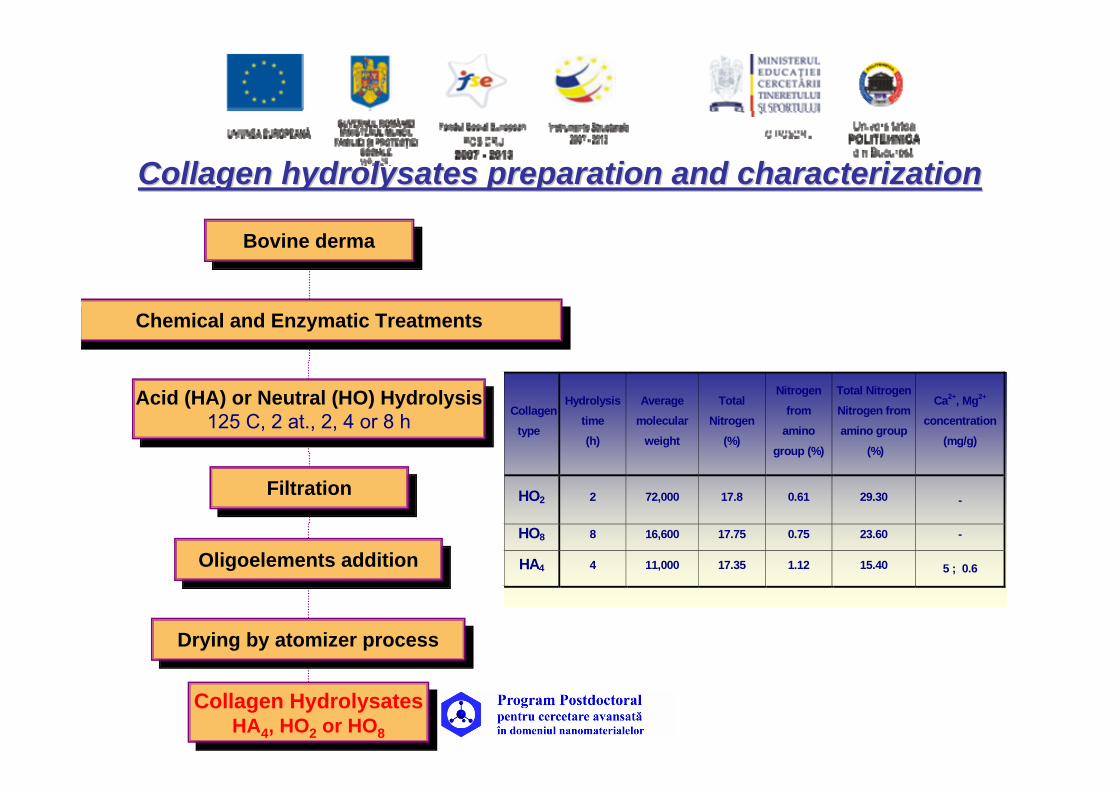
Collagen Collagen hydrolysateshydrolysates preparation and characterizationpreparation and characterization
Bovine dermaBovine derma
Chemical and Enzymatic TreatmentsChemical and Enzymatic Treatments
Acid (HA) or Neutral (HO) Hydrolysis125 C, 2 at., 2, 4 or 8 h
Acid (HA) or Neutral (HO) Hydrolysis125 C, 2 at., 2, 4 or 8 h
FiltrationFiltration
Oligoelements additionOligoelements addition
Drying by atomizer processDrying by atomizer process
Collagen HydrolysatesHA4, HO2 or HO8
Collagen HydrolysatesHA4, HO2 or HO8
Collagen type
Hydrolysis time (h)
Average molecular
weight
Total Nitrogen
(%)
Nitrogen from
amino group (%)
Total Nitrogen Nitrogen from amino group
(%)
Ca2+, Mg2+ concentration
(mg/g)
HO2 2 72,000 17.8 0.61 29.30 -
HO8 8 16,600 17.75 0.75 23.60 -
HA4 4 11,000 17.35 1.12 15.40 5 ; 0.6

• Poly(vinyl alcohol) PVA
Bioartificial materials based on blends of collagen
and
• Poly(ethylen glycol) PEG
• Poly(acrylic acid) PAA
PVA could interact with collagen through hydrogen bonds (weak interactation)
PEG could interact with collagen through hydrogen bonds (weak interactation)
High degree of compatibility between PAA and collagenStrong ionic interaction

Biopolymer films preparationBiopolymer films preparationPVAPEGPVAPVAPEGPEG
Mixing in different volumetric ratiosMixing in different volumetric ratios
Casting solution method in Petri dishesCasting solution method in Petri dishes
Dehydrohermal treatment in 3 steps
Dehydrohermal treatment in 3 steps
Biopolymer filmsBiopolymer films
PhosphatePhosphate
Patent 122282 /2009
HA4 , HO2 or HO8with and without
oligoelements

A: PVA and collagen hydrolysates (HO2)G1B: PVA and collagen hydrolysates (HO8)C: PVA and collagen hydrolysates (HA4) G3
(including Ca2+, Mg2+ ions)D: PVA and collagen hydrolysates (HA2) G2E: PVA and collagen hydrolysates (HA4) (including Ca2+,
Mg2+ and PO4 ions)
Types of Types of biofilmsbiofilms
F: PEG I and collagen gelG: PEG II and collagen gel

The AFM images The AFM images and dataand data
SAMPLE WITHOUT CALCIUM
AND MAGNESIUM IONS
SAMPLE WITH CALCIUM AND MAGNESIUM IONS
Samples Content
Root-meansquare
Roughnes(nm)
Fractaldimension
Biopolymer film based on
HA and PVA
With calcium and magnesium
ions794.6189 2.15
With calcium, magnesium, and
phosphateions
712.9020 2.14
Biopolymer film based
onHO and PVA
Without calcium, magnesium, and
phosphateions
30.3809 2.27

Collagen hydrolysatecontent (g)
0.3 0.6 1.2
Average pore radius (μ)
0.063 0.1655 2.8066
y = 3.2418x - 1.2576
-0.50
0.51
1.52
2.53
0 0.5 1 1.5Collagen hydrolysate content (g)
Average pore radius
(micron)*
*
*

Method of culture: direct contact method, using secondary cultures of human skin fibroblasts (HSF), obtained, grown, and subcultured at 37oC in a humidified incubator equilibrated with 5% CO2. Experimental cell culture medium (Sigma) was Dulbecco’s modified Eagle’s medium (DMEM) supplemented with 10% fetal bovine serum, 2 mM L-glutamine, 100 units/ml penicillin and 100 μg/ml streptomycin. The cells were seeded on the films at a density of 1 ×10⁵ cells/ml and cultured for up to 7 days.
Microscopic analysis: by an inverted microscope Nikon The boundary between the films and the cells monolayer was carefully controlled, to check if release from the films resulted in cell death. The cell viability was checked by the standard trypan blue exclusion test, MTT test and LDH test.
In vitro cell evaluationIn vitro cell evaluation

Tripan blue test is used to determine the number of viable cells present in a cell suspension. Principle : live cells possess intact cell membranes that exclude certain dyes, such as trypan blue, Eosin, or propidium, whereas dead cells do not. In this test, a cell suspension is simply mixed with dye and then visually examined to determine whether cells take up or exclude dye. A viable cell will have a clear cytoplasm whereas a nonviable cell will have a blue cytoplasm.
LDH test with kit SIGMA (TOX-7) « permits integrity evaluation of citoplasma membrane which leads at release of LDH ( lactat dehidrogenase enzyme) Optical densitiyat 520 n, are expression of LDH activity, being hiugher for higher citotoxicity
MTT test a quantitative method to estimate cell viability and cell citotoxicity, based on the reduction produced by a mithocondrial enzyme (succinatdehidrogenase) of yellow, water-soluble 3-(4,5-dimetiltiazol-2-il)-2,5-difeniltetrazolium bromide (MTT) into dark-blue, water-insoluble formazan.Thereduction is a parameter for mithocondrial integrity, and the amount of formazanis proportional to the number of viable cells.

PVA + HA4 (C1)
control
PEG I + collagen gel (F4)modified phenotype

•• image analyses using image analyses using SygmaSygma Scan Scan programmeprogramme
Image analyse for a selected group of cells
grown on collagen gel Representative cell from the
selected group

Cell viability versus contact angle for ternary biopolymeric films
50
60
70
80
90
100
control 1B 2B 3B 4B 5B 6B
Cell viability versus HA content

•
Ternary Ternary biofilmsbiofilms PVAPVA--HAPHAP--collagen gelcollagen gel
The different gravimetric ratios between the collagen gel, PVA and HAP lead to different values of contact angle and roughness. The increasing of hydroxyapatite content in ternary biofilms composition leads to decreasing of conatct angle and to increasing of roughness values.
30
35
40
45
2B 3B 4B 5B 6B 7B
Contact angle for ternary biofilms
0
1
2
3
4
5
6
7
Roughness valuesfor ternary biofilms (from1,97µm to 6,59µm with the increase content of HA
Patent 122287 /2009 Premiat 2011

10μm 10μm
Dermal fibroblast on ternay biofilm with HAP ratio 1/6
Compared to binary films viability is higher
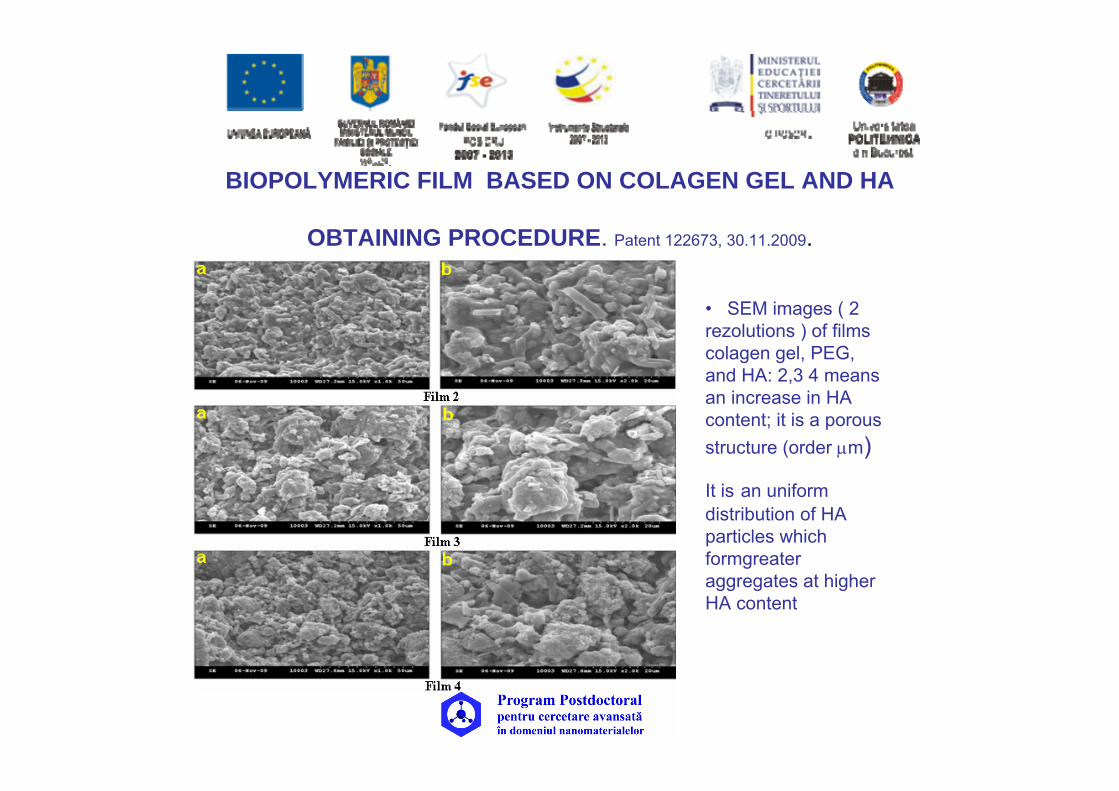
BIOPOLYMERIC FILM BASED ON COLAGEN GEL AND HA
OBTAINING PROCEDURE. Patent 122673, 30.11.2009.
• SEM images ( 2 rezolutions ) of films colagen gel, PEG, and HA: 2,3 4 means an increase in HA content; it is a porous structure (order μm)
It is an uniform distribution of HA particles which formgreateraggregates at higher HA content

In the films with PEG 4000 for the same ratio PEG/Colaggen contact angle decreases with the increase of HA. For the same ratio PEG/Colaggen and polymers and HA 1;1, but decreasing PEG molecular weight, the contact angle is increasing from 43 ( sample 2 ) to 56 (sample 10) and 63 (sample 13 ).Regarding Colagan amount the increase involve a slight deacrese of hydrophilic character

Important factors in decreasing citotoxic effect on osteoblaste hFOB 1.19 are molecular weight of synthetic polymer, ratio between synthetic and natural polymer and the amount of ceramic material HA. A higher amount of PEG with higher molecular weight, and a HA increase induce a smaller LDH release , promoting an increase of viability value.

Fibrobalst culture of fil Colagen gel PEG and HA
Composition of 2 films is based on gravimetric ratio 1 : 1 between synteticpolymer (PEG 4000) and colagen gel and a ratio 1 : 1,5 (filmA), respectively 1 : 2 (film B) between the mixture of the two polymers and HA.

Representative SEM image showing (left) the smooth surface of a porous Polylactic acid /Bioglass® scaffold and (right) after one day of immersion in SBF, where the typical cauliflower-like morphology of the apatite layer is observed. (B) Representative SEM image showing (left) the rough patterned surface of a porous PLLA/Bioglass® scaffold where also PEO was used as a porogen and (right) after 1 day of immersion in SBF, where a completely different calcium phosphate coating was formed.

Bioactive nanoparticles
AFM image in A) were used to produce multilayered coatings (B) by alternate dipping a substrate in a chitosan solution, water and nanoparticles suspension (C). Upon immersion in SBF an apatite layer could be detected onto the surface (D)

•Scheme of HA/PCL hybrid composite preparation by sol–gel technique for bone regeneration
•The fabrication of scaffolds was performed by salt-leaching technique using NaCl as porogen agent.
•composite scaffolds (polycaprolactone ) In SBF able to regenerate the natural bone.
Composites Science and TechnologyVol,70, 13,
15, 2010, Pages 1861-1868

In the first step, the physico-chemical characterization of composite material was performed to evaluate the composition and the interaction between the organic/inorganic phases.
SEM of HA/PCL hybrid composite material: (A) micro, (B) macroporosity, (C) TEM and EDAX analyses, and (D) of composite material.
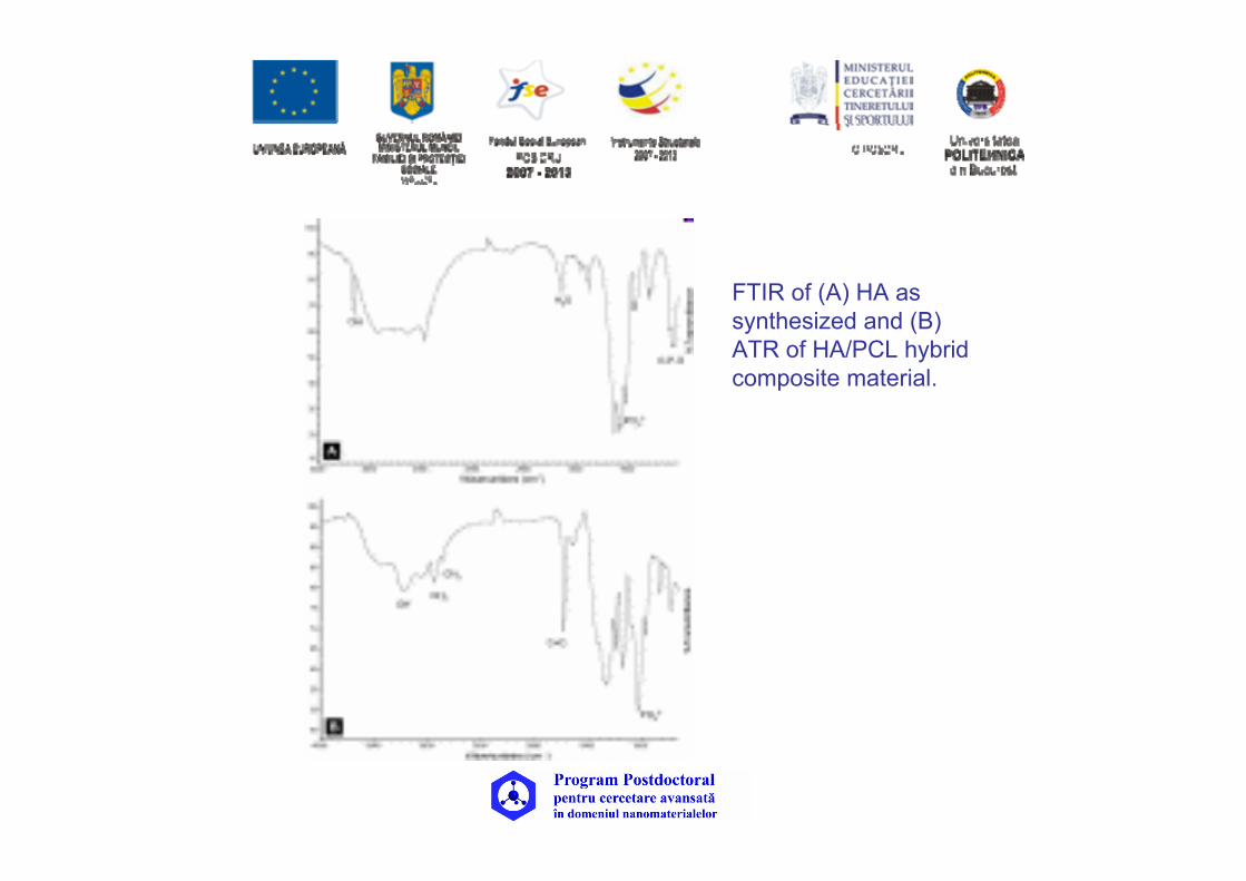
FTIR of (A) HA as synthesized and (B) ATR of HA/PCL hybrid composite material.
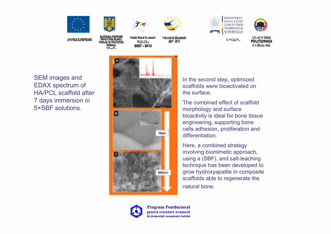
SEM images and EDAX spectrum of HA/PCL scaffold after 7 days immersion in 5×SBF solutions.
In the second step, optimized scaffolds were bioactivated on the surface.
The combined effect of scaffold morphology and surface bioactivity is ideal for bone tissue engineering, supporting bone cells adhesion, proliferation and differentiation.
Here, a combined strategy involving biomimetic approach, using a (SBF), and salt-leaching technique has been developed to grow hydroxyapatite in composite scaffolds able to regenerate the natural bone.

Image of scaffolds after trypan blue treatment: (A) PCL scaffold; HA/PCL hybrid scaffold (B) untreated; (C) after 3 days of treatment in 5 × SBF1; (D) after 7 days of treatment in 5 × SBF solutions.

Schematic representation of bacterial cellulose-based biomimetic composites with potential osteological applications
•The cellulose (most abundant biopolymer on earth) synthesized by the Gram-negative bacterium Gluconacetobacter xylinus•A single xylinus cell may polymerize up to 200,000 glucose molecules as a linear β-1-4 glucan chain that are excreted extracellularly as subelementary fibrils. •The latter are assembled into microfibrils that aggregate to form ribbons with a hierarchical structureBiopolymersISBN 978-953-307-109-1Edited by: Magdy ElnasharPublisher: InTech, September 2010


Composites of Bacterial celulose
Component Effect References
collagen Reduced sorption of proteases and interleukins Wiegand et al., 2006
DN gelatin hydrogels Enhanced mechanical strength Nakayama et al., 2004
Alginate Changed tensile strength Phisalaphong et al.,2008; New et al. 2010 Benzalkonium chloride antimicrobial activity Wei et al., 2011
PEG Decreased crystallinity, improved thermal stability Cai et al. 2010
Cotton gauze Increased water absorbency Meftahi et al., 2010
Aloe vera gel water sorption capacity, water vapor Saibuatong et al.,2010Permeability Improved mechanical strength, crystallinity,