Embed Size (px)
Citation preview

MODELLING THE BEHAVIOR OF CONCRETE MEMBERS:MODELLING THE BEHAVIOR OF CONCRETE MEMBERS:DEVELOPMENTS SINCE THE COMPLETION OF EN 1998DEVELOPMENTS SINCE THE COMPLETION OF EN 1998--3:20053:2005
Michael N. FardisMichael N. FardisUniversity ofUniversity of PatrasPatrasUniversity of University of PatrasPatras

Idealized skeleton curve - envelope to hysteresis loops
Yield Ultimate moment, Mu=My
MEffective elastic stiffness:
moment My
M < 0 8M
secant-to-yielding
Mres < 0.8Mu
member deformation:chord-rotation
δ yYield deformation
δ uUltimate deformation δ
chord rotationsection deformation:
curvature

Practical expressionsPractical expressionsact ca e p ess o sact ca e p ess o sfor the yield & failure properties for the yield & failure properties
developed for EN 1998developed for EN 1998--3:20053:2005theirtheir ad ancement sincead ancement since 20052005-- their their advancement since advancement since 2005 2005

D. BISKINIS, G. ROUPAKIAS & M.N. FARDIS, Cyclic Deformation Capacity of Shear-Critical RC Elements, Proceeding of fib Symposium, Athens, May 2003.M.N.FARDIS & D.BISKINIS, Deformation Capacity of RC Members, as Controlled by Flexure or Shear. Proceedings of International Symposium on Performance-based Engineering for Earthquake Resistant Structures honoring Prof. Shunsuke Otani University of Tokyo, Sept. 2003, pp. 511-530.D.BISKINIS, G.K. ROUPAKIAS & M.N.FARDIS, Resistance and Design of RC Members for Cyclic Shear, 14th Greek National Concrete Conference, Kos, Oct 2003 Vol B pp 363-374Oct. 2003, Vol. B, pp. 363 374.D.BISKINIS & M.N.FARDIS, Cyclic Strength and Deformation Capacity of RC Members, including Members Retrofitted for Earthquake Resistance, Proc. 5th
International Ph.D Symposium in Civil Engineering, Delft, June 2004, Balkema, Rotterdam, p. 1125-1133. D.BISKINIS, G.K. ROUPAKIAS & M.N.FARDIS, Degradation of Shear Strength of RC Members with Inelastic Cyclic Displacements, ACI Structural Journal, Vol. 101, No. 6, Nov.-Dec. 2004, pp.773-783.
S S S OS O O OS S O S S & S S S S f f C SM.N.FARDIS, D.BISKINIS, A. KOSMOPOULOS, S.N. BOUSIAS & A.-S. SPATHIS, Seismic Retrofitting Techniques for Concrete Buildings, Proc. SPEAR Workshop – An event to honour the memory of Jean Donea, Ispra, April 2005 (M.N.Fardis & P. Negro, eds.)S.N. BOUSIAS, M.N.FARDIS & D.BISKINIS, Retrofitting of RC Columns with Deficient Lap-Splices, fib Symposium, Budapest, May 2005.S.N. BOUSIAS, M.N.FARDIS, A.-S. SPATHIS & D.BISKINIS, Shotcrete or FRP Jacketing of Concrete Columns for Seismic Retrofitting, Proc. International Workshop: Advances in Earthquake Engineering for Urban Risk Reduction, Istanbul, May–June 2005.p q g g , , yD.BISKINIS & M.N.FARDIS, Assessment and Upgrading of Resistance and Deformation Capacity of RC Piers, Paper no.315, 1st European Conference on Earthquake Engineering & Seismology (a joint event of the 13th ECEE & the 30th General Assembly of the ESC), Geneva, September 2006.D.BISKINIS & M.N.FARDIS, Cyclic Resistance and Deformation Capacity of RC Members, with or without Retrofitting, 15th Greek National Concrete Conference, Alexandroupolis, Oct. 2006, Vol. B, pp. 495-506.D BISKINIS M N FARDIS Effect of Lap Splices on Flexural Resistance and Cyclic Deformation Capacity of RC Members Beton & Stahlbetonbau 102 2007D.BISKINIS, M.N.FARDIS, Effect of Lap Splices on Flexural Resistance and Cyclic Deformation Capacity of RC Members, Beton & Stahlbetonbau, 102, 2007D.BISKINIS & M.N.FARDIS, Cyclic Deformation Capacity of FRP-Wrapped RC Columns or Piers, with Continuous or Lap-Spliced Bars, 8th International Symposium on Fiber Reinforced Polymer Reinforcement for Concrete Structures (FRPRCS-8), Patras, July 2007.D.BISKINIS & M.N.FARDIS, Upgrading of Resistance and Cyclic Deformation Capacity of Deficient Concrete Columns, in “Seismic Risk Assessment and Retrofitting with special emphasis on existing low rise structures” (A.Ilki, ed.), Proceedings, Workshop, Istanbul, Nov. 2007, Springer, Dordrecht.D.BISKINIS & M.N.FARDIS, Cyclic Deformation Capacity, Resistance and Effective Stiffness of RC Members with or without Retrofitting, 14th World Conference on Earthquake Engineering, Beijing, paper 05-03-0153, Oct. 2008.D.BISKINIS & M.N.FARDIS, Chapter 15: “Upgrading of Resistance and Cyclic Deformation Capacity of Deficient Concrete Columns” , in “Seismic Risk Assessment and Retrofitting with special emphasis on existing low rise structures” (Ilki A et al, eds.), Springer, Dordrecht, 2009D BISKINIS & M N FARDIS Ultimate Deformation of FRP-Wrapped RC Members 16th Greek Nat Concrete Conference Paphos Oct 2009 paper 171106D.BISKINIS & M.N.FARDIS, Ultimate Deformation of FRP Wrapped RC Members, 16th Greek Nat. Concrete Conference, Paphos, Oct. 2009, paper 171106D.BISKINIS & M.N.FARDIS, Flexure-Controlled Ultimate Deformations of Members with Continuous or Lap-Spliced Bars, Structural Concrete, Vol. 11, No. 2, June 2010, 93-108.D.BISKINIS & M.N.FARDIS, Deformations at Flexural Yielding of Members with Continuous or Lap-Spliced Bars, Structural Concrete, Vol. 11, No. 3, September 2010, 127-138.D.BISKINIS & M.N.FARDIS, Effective stiffness and cyclic ultimate deformation of circular RC columns including effects of lap-splicing and FRP wrapping. Paper 1128, 15th World Conference on Earthquake Engineering, Lisbon, Sept. 2012.D.BISKINIS & M.N.FARDIS, Stiffness and Cyclic Deformation Capacity of Circular RC Columns with or without Lap-Splices and FRP Wrapping, Bulletin of Earthquake Engineering, Vol. 11, 2013, DOI 10.1007/s10518-013-9442-7.D.BISKINIS & M.N.FARDIS, Models for FRP-wrapped rectangular RC columns with continuous or lap-spliced bars, Engineering Structures, 2013 (submitted).

Experimental DatabaseExperimental Database1 Range/mean of parameters in tests for calibration of expressions1. Range/mean of parameters in tests for calibration of expressions
for the member chord rotation and secant stiffness at yielding1653 rectangular 214 rectangular 229 members of non 307 circular
Parameter 1653 rectangular beams/columns
214 rectangular walls
229 members of non-rectangular section
307 circular columns
min/max mean min/max mean min/max mean min/max mean
section depth or diameter, h (m) 0.1 / 2.4 0.31 0.4 / 3.0 1.19 0.2 / 3.96 1.4 0.15 /1.83 0.43
shear-span-to-depth ratio, Ls/h 1 / 13.3 3.78 0.45 / 5.53 1.92 0.45 / 8.33 2.03 1.1 / 10 3.77
section aspect ratio, h/bw 0.2 / 4 1.3 4 / 30 10.9 2.5 / 57 16.7 1.0 1.0
fc (MPa) 9.6 / 175 37.7 13.5 / 109 35.8 13.5 / 101.8 40.4 16.7 / 90 36.7
axial-load-ratio, N/Acfc -0.05 / 0.9 0.126 0 / 0.86 0.10 0 / 0.50 0.06 -0.1 / 0.7 0.137
transverse steel ratio, w (%) 0 / 3.54 0.62 0.05 / 2.18 0.54 0.04 / 2.44 0.7 0 / 8.83 0.86
total longitudinal steel ratio (%) 0 2 / 8 55 1 97 0 07 / 4 27 1 5 0 205 / 6 2 1 23 0 53 / 5 8 2 34total longitudinal steel ratio tot (%) 0.2 / 8.55 1.97 0.07 / 4.27 1.5 0.205 / 6.2 1.23 0.53 / 5.8 2.34
diagonal steel ratio, d (%) 0 / 1.68 0.027 0 / 0.25 0.005 - - - -
transverse steel yield stress fyw, MPa 118 / 2050 468 220 / 1375 443 160 / 1375 504 200 / 1728 454.2y fy
longitudinal steel yield stress fy, MPa 247 / 1200 440.2 276 / 1273 470 209 / 900 453 240 / 648 414.3

Experimental DatabaseExperimental Database2 Range/mean of parameters in tests for calibration of2. Range/mean of parameters in tests for calibration of
expressions for ultimate curvature in monotonic or cyclic loading
Parameter 415 rectangular beams/columns 59 rectangular walls
254 monotonic 160 cyclic 13 monotonic 46 cyclic
min/max mean min/max mean min/max mean min/max mean
section depth or diameter, h (m) 0.12 / 0.8 0.31 0.22 / 2.4 0.41 2.39 / 2.41 2.4 1.7 / 2.0 1.99
section aspect ratio h/bw 0 225 / 3 73 1 54 0 5 / 2 1 21 21 2 / 23 4 22 4 13 3 / 28 3 13 7section aspect ratio, h/bw 0.225 / 3.73 1.54 0.5 / 2 1.21 21.2 / 23.4 22.4 13.3 / 28.3 13.7
fc (MPa) 19.7 / 99.4 34.8 17.7 / 102.2 38.6 34.5 / 40.8 35.3 26.2 / 45.6 40.6
axial-load-ratio, N/Acfc 0 / 0.78 0.08 0 / 0.77 0.236 0.063 / 0.077 0.07 0.05 / 0.11 0.07
transverse steel ratio, w (%) 0 / 2.38 0.345 0.04 / 2.96 0.656 0.41 / 0.82 0.66 0.11 / 0.25 0.24
total longitudinal steel ratio tot (%) 0 / 3.68 1.4 0.37 / 4.19 1.82 0.88 / 1.76 1.35 0.07 / 0.77 0.63
t t l i ld t f MP 0 / 596 419 255 / 1402 477 2 440 / 483 443 3 465 / 562 502transverse steel yield stress fyw, MPa 0 / 596 419 255 / 1402 477.2 440 / 483 443.3 465 / 562 502
longitudinal steel yield stress fy, MPa 277 / 596 490 341 / 573 493.3 444 / 510 466.6 523 / 580 552

Experimental DatabaseExperimental Database3 Range/mean of parameters in tests for calibration of3. Range/mean of parameters in tests for calibration of
expressions for the member ultimate cyclic chord rotation1159 rectangular 95 rectangular 53 members of non 143 circular
Parameter 1159 rectangular beams/columns
95 rectangular walls
53 members of non-rectangular section
143 circular columns
min/max mean min/max mean min/max mean min/max meanmin/max mean min/max mean min/max mean min/max mean
section depth or diameter, h (m) 0.1 / 2.4 0.33 0.4 / 2.75 1.15 0.2 / 3.4 1.21 0.2 / 1.83 0.45
shear-span-to-depth ratio, Ls/h 1 / 13.3 3.7 0.5 / 5.53 2.15 0.65 / 8.33 2.85 1.77 / 10 4.22
section aspect ratio, h/bw 0.2 / 6 1.18 2.5 / 28.3 9.75 2.5 / 36 9.95 1.0 1.0
fc (MPa) 12.2 / 175 43.7 13.5 / 109 35.9 20.8 / 83.6 38.5 23.1 / 90 38.0
axial-load-ratio, N/Acfc -0.1 / 0.9 0.165 0 / 0.86 0.116 0 / 0.30 0.07 -0.09 / 0.7 0.15
transverse steel ratio, w (%) 0.015 / 3.37 0.82 0.05 / 2.18 0.63 0.04 / 2.09 0.59 0.1 / 8.83 0.94
total longitudinal steel ratio tot (%) 0 / 6.29 2.08 0.07 / 4.27 1.37 0.2 / 6.19 1.32 0.75 / 5.5 2.05
diagonal steel ratio, d (%) 0 / 1.68 0.028 0 / 0.25 0.004 - - - -
t t l i ld t f MP 118 / 1497 497 220 / 1375 435 3 178 / 1375 513 200 / 1569 482 5transverse steel yield stress fyw, MPa 118 / 1497 497 220 / 1375 435.3 178 / 1375 513 200 / 1569 482.5
longitudinal steel yield stress fy, MPa 281 / 1275 467.5 276 / 1273 471.2 331 / 596 438.7 240 / 648 428

Yield & failure properties of RC Yield & failure properties of RC e d & a u e p ope t es o Ce d & a u e p ope t es o Csectionssections

M-φ at yielding of section w/ rectangular compression zone (width b, effective depth d) –p ( , p )
section analysis• Yield moment (from moment-equilibrium & elastic σ-ε laws):
112111
2
3 116
123
15.02
Vyy
syycy
y EEbdM
• Yield moment (from moment-equilibrium & elastic σ-ε laws):
f
• 1, 2 : tension & compression reinforcement ratios, v: “web” reinforcement ratio, ~uniformly distributed between 1, 2 : (all normalized to bd); 1 = d1/d.
C t t i ldi f t i t l dE
f
ys
yy
1
2/1
• Curvature at yielding of tension steel:• from axial force-equilibrium & elastic σ-ε laws ( = Es/Ec):
ABAy 2/122 2
y
vy
v bdfNB
bdfNA 112121 15.0,
dEf
d yc
c
y
cy
8.1
yy ff• Curvature at ~onset of nonlinearity of concrete:
yy
11212121 15.0,8.1
vc
vsc
v Bbdf
NbdE
NA

Moment at corner of bilinear envelope to experimental moment-deformation curve vs yield moment from section analysisdeformation curve vs yield moment from section analysis
Left: 2085 beams/columns, CoV:16.3%; Right: 224 rect. walls, CoV:16.9% 10500
4000
di M 1 025M
9000
10500
median: My,exp= 0.99My,pred
3000
kNm
)
median: My,exp=1.025My,pred
6000
7500
Nm
)
2000
My,
exp
(k
3000
4500
My,
exp
(kN
0
1000
0
1500
M
Bias by +2 5% or 1% because corner of bilinear envelope of the
00 1000 2000 3000 4000
My,pred (kNm)
00 1500 3000 4500 6000 7500 9000 10500
My,pred (kNm)
Bias by +2.5% or -1%, because corner of bilinear envelope of the experimental moment-deformation curve ≠ 1st yielding in section. Same bias
considered to apply to predicted yield curvature.

Empirical formulas for yield curvature - section w/
f541 f751
rectangular compression zone
dEf
s
yy
54.1
hEf
s
yy
75.1for beams or columns:
1.37 yy
s
fE d
1.47 y
ys
fE h
for walls:
Empirical expressions don’t have a bias w.r.to experimental yield moment; but scatter is larger:y ; gIn ~2100 test beams, columns or walls: CoV: ~18%

Flexural Flexural failures failures -- columnscolumns

Flexural Flexural failures failures -- beamsbeams

Conventional definition of ultimate deformationConventional definition of ultimate deformationThe value beyond which, any increase in deformation cannot increase the resistance above 80% of the maximum previous p(ultimate) resistance.
250250 200Q RC
0
50
100
150
200
rce
(kN
)
0
50
100
150
200
rce
(kN
)
50
100
150
N)
Q-RC
-200
-150
-100
-50
0
a
App
lied
for
-200
-150
-100
-50
0
a
Appl
ied
for
-100
-50
0
Forc
e (k
N
conventional ultimate deformation coincides
-125 -100 -75 -50 -25 0 25 50 75 100 125-250
Deflection (mm)
100
150
200
250
N)
-125 -100 -75 -50 -25 0 25 50 75 100 125-250
Deflection (mm)
100
150
200
250
-120 -90 -60 -30 0 30 60 90 -200
-150
-100
Displacement (mm)
deformation coincides w/ real failure conventional ultimate deformation
before “real” failure
-100
-50
0
50
100
App
lied
forc
e (k
-100
-50
0
50
100
pplie
d fo
rce
(kN
) Displacement (mm)
-125 -100 -75 -50 -25 0 25 50 75 100 125-250
-200
-150b
Deflection (mm)-125 -100 -75 -50 -25 0 25 50 75 100 125
-250
-200
-150b
Ap
Deflection (mm)

Ultimate curvature of section with rectangular compression zone from section analysiscompression zone, from section analysis
C t l• Concrete σ-ε law:– Parabolic up to fc, εco, c co
– constant stress (rectangular) for εco< ε < εcu
• Steel σ ε law:• Steel σ-ε law:– Elastic-perfectly plastic, if steel strain rather low and
t f il fi tconcrete fails first;– Elastic-linearly strain-hardening, if steel strains are
relatively high and steel breaks at stress and strain ft, εsu.

Possibilities for ultimate curvature:
su
1. Section fails by rupture of tension steel, εs1= εsu, before extreme compression fibers reach their ultimate strain (spalling), εc < εcu →Ultimate curvature occurs in unspalled section due to steel rupture: dsu
su
1Ultimate curvature occurs in unspalled section, due to steel rupture:
2. Compression fibres reach their ultimate strain (spalling): εc = εcu →the confined concrete core becomes now the member section. Two possibilities:
i. The moment capacity of the spalled section, ΜRo, never increases above 80% of the moment at spalling Μ : Μ < 0 8Μ →
dcu
cucu
80% of the moment at spalling, ΜRc: ΜRo< 0.8ΜRc → Ultimate curvature occurs in unspalled section, due to the concrete:
ii. Moment capacity of spalled section increases abovep y p80% of the moment at spalling: ΜRo> 0.8ΜRc →The confined concrete core is now the member section and Cases 1 and 2(i) li d f th fi d th t ibiliti f tt i t2(i) - applied for the confined core - are the two possibilities for attainment of the ultimate curvature → φsu, φcu calculated as above but for the confined core; the minimum of the two is the ultimate curvature.
cu
co
cu
co
cus
ycRc
ffbdM
421
321
31)1)((
12))(1(
2
11
2112

Ultimate curvature of section w/ rectangular compression zone for steel rupture: d
susu
1
tt
cocuysutt
coysu ffff
1111 1133
1
Steel ruptures before concrete crushes, after compression steel yields, if ν: dsu1
cusu
cusu
y
tv
y
t
sucuysu
ysu
y
tv
y
t
ysu ff
ff
ff
ff
1
111212 1
11132
13
• ξsu calculated from axial force equilibrium for:
t
vy
t
su
co
y
t
suf
ff
ff
12
13
1 1211
vy
t
su
co
ff
1
311 1
ν=N/bdfc, ω1, ω 2 : tension & compression mech. reinforcement ratios, ωv: “web” mech. reinforcement ratio ~uniform distribution between ω1, ω 2 (ω= fy/fc); 1=d1/d.
ysutt
coysu ff
13
112
11
1, 2 ( y ); 1 1
Steel ruptures before concrete crushes or compression steel yields, if ν:
ysuyv
yysu ff
2112
• ξsu from: 1)1(23
1 2
1
y
su
sus
t
y
tv
su
co
Ef
ff
01)1(23
1)1(3
21
)(
21
11211
121
1
y
su
sus
t
y
t
y
su
y
t
su
co
y
su
sus
t
y
t
y
su
y
t
su
co
ysusysu
Ef
ff
ff
Ef
ff
ff
f

Ultimate curvature of section w/ rectangular compression zonefor concrete crushing:
dcu
cu
Concrete crushes after tension steel yields, w/o compression steel yielding, if ν :co
cuycuv
31
dcu
• ξcu from axial force equilibrium, for:ycuycu
yv
311 11
112
Concrete crushes w/ tension & compression steel yielding if ν :
012
11)1(23
1 1
1
12
1
121
22
1
y
cuv
y
cu
y
cu
ycu
ycuv
cu
co
11
Concrete crushes w/ tension & compression steel yielding, if ν :
ycu
cocu
ycu
ycuv
ycu
cocu
ycu
ycuv
3
131
1 11
12111
12
vcu
co
vcu
2
311
11
1
1211
• ξcu from:
Concrete crushes after compression steel yields w/o tension steel yielding if ν : Concrete crushes after compression steel yields, w/o tension steel yielding, if ν :
• ξcu from:
ycu
cocu
ycu
ycuv 31 1
112
0121)1(23
11
111
122
2
1
y
cuv
y
cu
y
cu
ycu
ycuv
cu
co

Confined core after spalling of concrete cover. Parameters are denoted by an asterisk and computed with: b, d, d1 replaced by geometric parameters of the core: bc, dc, dc1;
N li d t b d i t d f bd
Unconfined full section – Steel rupture
δ1 satisfies Eq.(3.38)?
yes no
Ruptureof tension steel
N, 1, 2, v normalized to bcdc, insteadof bd; σ-ε parameters of confined concrete, fcc, cc, used in lieuof fc, cu
no
yes su from
Eq.(3.41) ν<νs,y2 - LHS
Eq.(3.39)? ν<νs,c - RHS Eq.(3.39)?
yes
φsu from Eq.(3.36)
no
yes *su from Eq.(3.41)
ν*<ν*s,y2 - LHS Eq.(3.39)?
Unconfined full section – Spalling of concrete cover
ν<νs,c - RHS Eq.(3.39)?
yes su from Eq.(3.40)
q ( )
no
no
ν*<ν*s,c - RHS Eq.(3.39)?
yes *su from Eq.(3.40)
φsu from Eq.(3.36)
δ1 satisfies
Eq.(3.42a)? yes
ν<νc y2 - LHS cu from yes
no
ν< c y1 - LHSyes
Failure of compression zone (concrete)
no
ν<νc,y2 LHS Eq.(3.44)?
ν<νc,y1 - RHS Eq (3 44)?
Eq.(3.47)
cu from Eq (3 46)
no
no ν< c,y2 - RHS E (3 48)?
ν c,y1 LHS Eq.(3.48)?
no
no
ν*<ν*c,y2 - LHS Eq.(3.44)?
*cu from Eq.(3.47)
yes
Eq.(3.44)? Eq.(3.46)
cu from Eq.(3.45)
Eq.(3.48)?
cu from Eq.(3.49)
yes yes
no
noν*<ν*c,y1 - RHS Eq(344)?
*cu from Eq(346)
φcu from Eq.(3.37)
Compute moment resistances: MRc (of full, unspalled section) and MRo (of confined core, after spalling of cover).
MR < 0 8MR ? φcu from yes
*cu from Eq.(3.45)
Eq.(3.44)? Eq.(3.46)
yes
MRo< 0.8MRc? φEq.(3.37)
no
Ultimate curvature of confined core after spalling of concrete cover

Test results vs ultimate curvature w/ failure strains for cyclic flexure per EN 1998-3:2005 :
Steel: εsu: 2.5%, 5%, 6% for steel class A, B, C per Eurocode 2
ffαρε /5.0004.0 0 8 ccywsccu ffαρε /5.0004.0,
0,7
0,8
median: φu,exp=0.96φu,pred
cyclic test results0,5
0,6
0,4
,
exp
(1/m
) Cyclic all
Concrete crushing
Steel rupture
Median 0 96 0 90 0 98
0,2
0,3φu,
e Median 0.96 0.90 0.98
C.o.V. 46.7% 55.1% 38.0%
No 205 97 108
0,1 cyclic, slip
cyclic, no-slip
No. 205 97 108
00 0,1 0,2 0,3 0,4 0,5 0,6 0,7 0,8
φu,pred (1/m)

102• Monotonic flexure:
Test results vs ultimate curvature w/ failure strains for cyclic flexure per Biskinis & Fardis 2010 (adopted in fib MC2010):
Kmmhw
ccu
1285.0
)(100035.0*
10
2*
Monotonic flexure:•max. available steel strain: (7/12)εsu
• Cyclic flexure:
Kmmhw
ccu
12.0
)(100035.0* •max. available steel strain: (3/8)εsu
1.2
monotonic & cyclic data, no. 474, median=1 00
1median: φu,exp=φu,pred
median=1.00, CoV=49.7%
0 6
0.8
1/m
)
cyclic test data:0.4
0.6
φu,
exp
(1
Cyclic Concrete Steel
0.2cyclic, slipcyclic, no-slipmonotonic, slip
t i li
all crushing rapture
Median 0.99 0.99 1.01
00 0.2 0.4 0.6 0.8 1 1.2
φu,pred (1/m)
monotonic, no-slip C.o.V. 44.2% 52.6% 34.2%
No. 205 97 108

Yield & failure properties of RC Yield & failure properties of RC e d & a u e p ope t es o Ce d & a u e p ope t es o Cmembersmembers

Flexural Flexural behaviorbehavior at member level (at member level (MomentMoment--chord rotation)chord rotation)
Definition of chord rotations, θ, at member endschord rotation)chord rotation)
Elastic moments at ends A, B from chord rotations at A, B: • ΜΑ = (2ΕΙ/L)(2θΑ+θΒ), • ΜΒ = (2ΕΙ/L)(2θΒ+θΑ)

Fixed-end rotation of member end due to bar slippage from their anchorage zone beyond member end
Sli f t i b f i b d d ti ( f j i• Slippage of tension bars from region beyond end section (e.g. from joinor footing) →rigid body rotation of entire shear span = fixed end rotation θrigid-body rotation of entire shear span = fixed-end rotation, θslip
(included in measured chord-rotations of test specimen w.r. to base or joint; doesn’t affect measured relative rotations between any two member sections).affect measured relative rotations between any two member sections).
• If s = slippage of tension bars from anchorage → θslip= s/(1-ξ)d• If bond stress uniform over straight length lb of bar beyond section of maximumg g b y
moment → bar stress decreases along lb from σs (=fyL at yielding) at section omaximum M to zero at end of lb → s=σslb/(2Es) l b d f d d it l th ( A /( d ) d /4) di id d b b• lb= bond force demand per unit length (=Asσs/(dbL)=dbLσs/4), divided by ~bonstrength (assume =√fc)
• ε (=σ /E )/(1-)d = φεs( σs/Es)/(1 )d φ• At yielding of member end section
fd(fyL, fc in MPa )
c
ybLyslipy f
fd
8,

Fixed-end rotation of member end due to rebar pull-out from anchorage zone beyond member end, at member yieldingφy,measured/(φy,predicted+y,slip,/lgauge) no.160 measurements w/ slip:
median = 1.0, C.o.V = 34%
Ratio: 2.25
2.5
experimental-to-predicted yield
t ( /1.75
2
e to
slip
)
curvature (w/ correction for fixed-end-
1.25
1.5
inci
ples
+φ y
,due
fixed endrotation) in terms of gauge length 0.75
1
xp / (φ
y,1st
-pri
0.25
0.5φy,
ex
0
0 0.25 0.5 0.75 1 1.25 1.5lgauge / h

Chord rotation of shear span at yielding of end sectionper EN 1998-3:2005
slipyslVs
yy aLhzaL
,5.110014.03
• Rect. beams or columns:
R t t ll sL3
slipyslVs
yy azaL,0013.0
3
• Rect. or non-rect. walls:
“Shift rule”: 3Shift rule : Diagonal cracking shifts value of force in tension reinforcement to a section at a distance from member end equal to z (internal lever arm) • z = d d in beams columns or walls of barbelled or T section• z = d-d1 in beams, columns, or walls of barbelled or T-section, • z = 0.8h in rectangular walls. – av = 0, if VRc > My/Ls;
1 if V ≤ M /L– av = 1, if VRc ≤ My/Ls .VRc = force at diagonal cracking per Eurocode 2 (in kN, dimensions in m, fc in MPa):
dbANf
df
dV wcccR
15.02.012.0135,100180max 3/16/13/1
1, Add c
– asl = 0, if no slip from anchorage zone beyond end section; – asl = 1, if there is slip from anchorage zone beyond end section.

Test-model comparison – θy Beams/rect. columns, no. tests: 1653
3
3.5
median=1.01, CoV=32.1% 2.5
3
2%
)
median: θy,exp=1.01θy,pred
1.5
θ y,e
xp(%
1
θ
0
0.5
rect. beams / columns0
0 0.5 1 1.5 2 2.5 3 3.5
θy,pred (%)

Test-model comparison – θy Walls, no. tests: 386a s, o tests 386
1
1,2
1
1,2
0,8
1
0,8
1
0 4
0,6
θ y,e
xp(%
)
median: θy,exp=1.01θy,pred
0 4
0,6
θ y,e
xp(%
)
median: θy,exp=0.97θy,pred
0,2
0,4θ
Rectangular walls0,2
0,4θ
Rectangular walls
00 0,2 0,4 0,6 0,8 1 1,2
θ (%)
Non-rectangular Walls0
0 0,2 0,4 0,6 0,8 1 1,2
θ (%)
Non-rectangular Walls
Modified expression adopted in MC2010Expression in EN 1998-3:2005median=0.97, CoV=31.1% 50 00045 1s VL a z h
θy,pred (%)θy,pred (%)
median=1.01, CoV=30.9%,0.00045 1
3 3s V
y y sl y slips
aL

Test-model comparisons - θyCircular columns - not in EN 1998-3:2005: no. tests: 291
,20.0027 1 min 1;
3 15s V s
y y sl y slipL a z L a
D
3 15y y y pD
median=1.00, CoV=31.7%2,5
,2
median: θy,exp=θy,pred
1,5
p (%
)
1θ y,e
x0,5
circular0
0 0,5 1 1,5 2 2,5
θy,pred (%)

Effective elastic stiffness, EIeff(for linear or nonlinear analysis)(for linear or nonlinear analysis)
Part 1of EC8 (for design of new buildings): EIeff : secant stiffness at yielding =50% of
uncracked gross-section stiffness.- OK in force-based design of new buildings (safe-
sided for forces);- Unsafe in displacement-based assessment for
displacement demands).
More realistic:sy
eff
LMEI
3
secant stiffness at yielding of end of shear span L =M/V
y3
end of shear span Ls=M/V

Test-model comparison – EIeffBeams/rect. columns, no. tests: 1616
600
median=1.00, CoV=32.1%
500 median: (MyLs/3θy)exp =MyLs/3θy)pred
400
MNm
2 )LM 300
3θy) e
xp (M
y
syeff
LMEI
3
200
(MyL
s/3y
0
100
rect. beams / columns0
0 100 200 300 400 500 600
(MyLs/3θy)pred (MNm2)

4000median: 1250
1500
median:
Test-model comparison – EIeff Walls, no. tests: 386sy LM
EIdetail
With i f θ
3000
MNm
2 )
median: (MyLs/3θy)exp=1.035(MyLs/3θy)pred
1000
1250
MNm
2 )
median: (MyLs/3θy)exp=1.035(MyLs/3θy)pred
y
syeffEI
3
With expression for θy in EN 1998-3:2005median=1 035 1000
2000
yLs/3θ
y)exp(M
500
750
yLs/3θ
y)exp(M
median=1.035CoV=42.8%
0
1000
0 1000 2000 3000 4000(M
y
( / θ ) ( 2)
non-rectangular walls
rectangular walls
0
250
0 250 500 750 1000 1250 1500
(My
( / θ ) ( 2)
non-rectangular walls
rectangular walls
4000median: (M L /3θ ) =0 98(M L /3θ ) d
1250
1500
median: (M L /3θ ) =0 98(M L /3θ ) d
detail(MyLs/3θy)pred (MNm2) (MyLs/3θy)pred (MNm2)
With new expression for θ of walls
3000
p(M
Nm
2 )
(MyLs/3θy)exp 0.98(MyLs/3θy)pred
750
1000
p(M
Nm
2 )
(MyLs/3θy)exp 0.98(MyLs/3θy)pred
for θy of walls (adopted in MC2010)median=0.98 1000
2000
MyL
s/3θ
y)exp
non-rectangular walls 250
500
MyL
s/3θ
y)exp
non-rectangular walls
CoV=41.1%0
0 1000 2000 3000 4000
(M
(MyLs/3θy)pred (MNm2)
non-rectangular walls
rectangular walls
0
250
0 250 500 750 1000 1250 1500(M
(MyLs/3θy)pred (MNm2)
non-rectangular walls
rectangular walls

Test-model comparison – EIeffCircular columns - not in EN 1998-3:2005, no. tests: 273
median=0.99, CoV=31.2%
,sy
eff
LMEI
3 ed a 0 99, Co 3 %
3500
4000median: (MyLs/3θy)exp=0.99(MyLs/3θy)pred
175median: (MyLs/3θy)exp=0.99(MyLs/3θy)pred
y3
3000
3500
m2 )
(MyLs/3θy)exp 0.99(MyLs/3θy)pred
125
150
m2 )
(MyLs/3θy)exp 0.99(MyLs/3θy)pred
2000
2500
exp
(M
Nm
75
100
exp
(M
Nm
1000
1500
MyL
s/3θ y
) e
50
75
MyL
s/3θ y
) e
0
500
(M
circular0
25(Mcirculardetail
0 500 1000 1500 2000 2500 3000 3500 4000
(MyLs/3θy)pred (MNm2)0 25 50 75 100 125 150 175
(MyLs/3θy)pred (MNm2)

Empirical secant stiffness to yielding, EIeff, independent of amount of reinforcement - not in EN 1998-3:2005
)](;50min[048.016.0;maxln8.0 MPa
AN
hLa
IEEI seff
AhIE ccc
(all variables known before dimensioning the longitudinal reinforcement)(all variables known before dimensioning the longitudinal reinforcement)
– If there is slippage of longitudinal bars from their anchorage zoneIf there is slippage of longitudinal bars from their anchorage zone beyond the member end: • a = 0.081 for columns;;• a = 0.10 for beams or non-rectangular walls (barbelled, T-, H-section);• a = 0.115 for rectangular walls;a 0.115 for rectangular walls; • a = 0.12 for members with circular section.– If there is no slippage of longitudinal bars: effective stiffness x 4/3If there is no slippage of longitudinal bars: effective stiffness x 4/3

Test-model comparison – Empirical EIeff, independent of amount of reinforcement - not in EN 1998-3:2005
Beams/columns
600of amount of reinforcement not in EN 1998 3:2005
no. tests: 1616median=1.00CoV=36 1%
500
median: (MyLs/3θy)exp =EIpredCoV=36.1%
400M
Nm
2 )
( y s y)exp pred
300
θ y) e
xp (M
200
MyL
s/3θ
100(M
00 100 200 300 400 500 600
EIpred (MNm2)

detail4000median: (MyLs/3θy)exp=EIpred
1500
median: (MyLs/3θy)exp=EIpred
Test-model comparison –Empirical EI ff
detail
2000
3000
xp(M
Nm
2 )
1000
xp(M
Nm
2 )
Empirical EIeffindependent of reinforcement , not
Wallsno tests: 386
1000
2000
MyL
s/3θ
y)ex
non-rectangular walls
500
MyL
s/3θ
y)ex
non-rectangular walls
in EN1998-3: 2005
no. tests: 386median=1.00CoV=44.6%
00 1000 2000 3000 4000
(M
EIpred (MNm2)
non rectangular walls
rectangular walls
00 500 1000 1500
(M
EIpred (MNm2)
non rectangular walls
rectangular walls
3000
3500
4000median: (MyLs/3θy)exp=EIpred 150
175median: (MyLs/3θy)exp=EIpred
EIpred (MNm ) EIpred (MNm )
detail
2000
2500
3000
xp
(MN
m2 )
100
125
xp
(MN
m2 )
Circular columnsno tests: 273
1000
1500
(MyL
s/3θ y
) ex
25
50
75
(MyL
s/3θ y
) ex
no. tests: 273 median=0.995 CoV=31.4%
0
500
0 500 1000 1500 2000 2500 3000 3500 4000
(
EIpred (MNm2)
circular0
25
0 25 50 75 100 125 150 175(
EIpred (MNm2)
circular

L50
Flexure-controlled ultimate chord rotation from curvature & plastic hinge length per EN 1998-3:2005
s
plplyuy
pluyu L
LLφφθθθθ
5.01)(
• y: yield curvature (section analysis);
dd su
su
cccu
ccuu )1(
,min,
,
Option 1: Confinement per Eurocode 2O ti 2 N EN 1998 3 2005
ywsxccc fαρff 5.2125.1 86.0/7.31 cywsxccc ffff
Option 2: New, per EN 1998-3:2005ywsxccc fαρff 5:05.0 cywsx ffαρ
:05.0 cywsx ffαρ
cywsxcoccu ff /2.0, y
ccywsxccu ff /5.0004.0,
yy
cybs ffdhLL 24.017.01.0pl
index c: confined;
cybs ffdhLL /11.02.030/pl : confinement effectiveness:
rectangular section:
ihh bssα 111
2
ρs: stirrup ratio; Ls=M/V: shear span at member end; h: section depth;
– rectangular section: – circular section & hoops:sh: centerline spacing of stirrups,
cccc hbhb
α6
12
12
12
21
c
h
Dsα
h: section depth;db: bar diameter; fy, fc: MPa
Dc, bc, hc: confined core dimensions to centerline of hoop; bi: centerline spacing along section perimeter of longitudinal bars (index: i) engaged by a stirrup corner or cross-tie.

Test-model comparison – ultimate chord rotation from curvatures & plastic hinge length per EN 1998-3:2005, no. tests: 1100
Option 1: confinement per EC2median=0.88, CoV=52.3% Option 2: new confinement per EC8-3
di 0 91 C V 52 2%
12 5Cyclic loading median:θ =0 91θ
median=0.91, CoV=52.2%17,5
Cyclic loading median:θ =0 88θ
10
12,5y g median: θu,exp=0.91θu,pred
12,5
15median: θu,exp=0.88θu,pred
7,5
exp
(%)
10
exp
(%)
5θ u,e
5
7,5
θ u,e
0
2,5beams & columnsrect. wallsnon-rect. sections
0
2,5 beams & columnsrect. wallsnon-rect. sections
00 2,5 5 7,5 10 12,5
θu,pred (%)
00 2,5 5 7,5 10 12,5 15 17,5
θu,pred (%)

Flexure-controlled ultimate chord rotation of rect. beams, columns, walls, non-rect. walls & circular columns from curvatures & plastic
hi l th b Bi ki i & F di 2010 2013 d t d i fibMC2010Flexure-controlled ultimate chord rotation, accounting separately for slippage in yield-penetration length, from yielding till ultimate deformation:
hinge length by Biskinis & Fardis 2010, 2013 - adopted in fibMC2010
slippage in yield penetration length, from yielding till ultimate deformation:
pl
plyuslipuslyu LL
La2
1)(, 43f
Confinement per fib MC2010:
sL2
2– Monotonic loading - Rect. beams, columns, walls, non-rectangular walls:
5.31
c
ywwccc f
fff
,57.0)(
100035.02
,cc
yww
occu f
fαρmmh
ε
g , , , g
L
hL s9i04011
alnosumonsu min,, 127
– Cyclic loading:
h
hL smonpl ;9min04.01.1,
4010003502
yww fαρε
3
hLhL s
cypl ;9min3112.0,
,4.0)(
0035.0,cco
ccu fmmhε
alnosucysu min,, 8
• Rect. beams/columns/walls, non-rect. walls:
hcypl 3,
• Circular columns:
DLDL s
circypl ;9min6116.0,,

Post-yield fixed-end rotation of member end due to bar slippage from yield penetration length beyond member end, from yielding
till lti t fl l d f ti Bi ki i & F di 2010 2013till ultimate flexural deformation per Biskinis & Fardis 2010, 2013 -adopted in fibMC2010 (not in EN 1998-3:2005)
2/1659 dd• Monotonic loading:
• Cyclic loading: 2/105.5 bLbLli dord
2/165.9, uybLubLsli pu dord
Cyclic loading: 2/105.5, uybLubLslipu dord
C l t ll t fComplete pull-out of beam bars, due to short anchorage inshort anchorage in corner joint← →

Test-model comparison – Cyclic ultimate chord rotation from curvatures & plastic hinge length per Biskinis & Fardis 2010, 2012
Rect. beams/columns/walls, non-rect. walls - no. tests: 1100 Circular columns – no. tests: median=1.00, CoV=43.2%
C li l di
16
143, median=1.00, CoV=30.3%
10
12,5Cyclic loading
median: θu,exp=θu,pred
12
14
median: θu,exp=θu,pred
7,5
10
p (%
)
8
10
(%
)
5θ u,e
xp
4
6
8
θ u,e
xp
0
2,5 beams & columnsrect. wallsnon-rect. sections
2
4
circular00 2,5 5 7,5 10 12,5
θu,pred (%)
o ect sect o s0
0 2 4 6 8 10 12 14 16
θu,pred (%)
circular

Empirical cyclic flexure-controlled ultimate chord rotation of rect. beams/columns/walls, non-rect. walls in EN1998-3:2005 & fibMC2010
)25.1(25);01.0(max)';01.0(max)3.0(016.0 dc
ywsx
10035.0
s
225.0
cumρf
fαρ
ν
hLf
ωωθ
or:)275.1(25
);010(max)';01.0(max)25.0(0145.0 dc
ywsx
10035.0
s2.0c
3,0
yumplum
ρf
fαρ
ν
hLf
ωωθθθ
, ': mechanical ratio of tension (including web) & compression steel; : N/bhfc (b: width of compression zone; N>0 for compression);
);01.0(max hω
c ( p p )Ls/h : M/Vh: shear span ratio;α : confinement effectiveness factor :
ihh
hbb
hs
bsα
61
21
21
2
sx: Ash/bwsh: transverse steel ratio // direction of loading;d: ratio of diagonal reinforcement.
W ll 1st i di id d b 1 6 2nd lti li d b 0 6
cccc hbhb 622
• Walls: 1st expression divided by 1.6; 2nd multiplied by 0.6• Cold-worked brittle steel: 1st expression divided by 1.6; 2nd by 2.0
Non-seismically detailed members with continuous bars • Plastic part, pl
um=θum-y, of ultimate chord rotation: divided by 1.2.

Test-model comparison – Empirical cyclic ultimate chord rotation of members with seismic detailing per EN 1998-3:2005 – no. tests 1100
Model for total um Model with um=y+pl
median=1.00, CoV=37.8% median=1.00, CoV=37.6%
12,5Cyclic loading
median: θu,exp=θu,pred 12,5 median: θu,exp=θu,predmedian: θu,exp=θu,pred
Cyclic loading
10
, , p ,p
10
, p ,pu,exp u,pred
7,5
exp
(%)
7,5
,exp
(%)
5θ u,
5% fractile: θu,exp=0.5θu,pred
5
θ u,
5% fractile: θu,exp=0.52θu,pred
0
2,5 beams & columnsrect. wallsnon-rect. sections
0
2,5 beams & columnsrect. wallsnon-rect. sections
u,exp u,pred
00 2,5 5 7,5 10 12,5
θu,pred (%)
00 2,5 5 7,5 10 12,5
θu,pred (%)

Test-model comparison – Empirical cyclic ultimate chord rotation of members without seismic detailing per EN 1998-3:2005 – no. tests 48
Model for total um Model with um=y+pl
median=1.00, CoV=30.6% median=0.99, CoV=31.8%
8
9
median:θ =θ d 8
9
6
7
8 median: θu,exp=θu,pred
7
8 median: θu,exp=0.99θu,pred
5
6
xp (%
)
5
6
xp (%
)3
4θ u,e
x
3
4θ u,e
x
1
2
1
2
00 1 2 3 4 5 6 7 8 9
θu,pred (%)
00 1 2 3 4 5 6 7 8 9
θu,pred (%)

General empirical ultimate chord rotation of rect. beams/columns/ walls & non-rect. walls per Biskinis & Fardis 2010, adopted in fib
MC2010 (not in EN1998 3:2005)MC2010 (not in EN1998-3:2005)
dc
yww
f
f
cs
slcyhbwst
plu f
hL
bhaa
1002.03
1
1
2 225.125;9min);010max();01.0max(2.0;10min;5.1max052.016.01)525.01(
αsthbw:
0.022 for hot-rolled or Tempcore bars; 12,5 median: θu,exp=θu,predmedian: θu,exp=θu,predcyclic loading
w hb 1);01.0max(
0.022 for hot rolled or Tempcore bars; 0.0095 for brittle cold-worked bars;αcy:
1 f li l di
10
= 1 for cyclic loading, = 0 for monotonic;αsl:
7,5
θ u,e
xp (%
)
sl= 1 if slippage of long. bars from anchorage zone is possible, = 0 otherwise; 2 5
5
θb & l
5% fractile: θu,exp=0.51θu,pred
= 0 otherwise;bw: width of (one) web
0
2,5
0 2 5 5 7 5 10 12 5
beams & columnsrect. wallsnon-rect. sections
Non-seismically detailed members:• pl
um=θum-y divided by 1.2. no. tests: 1100, median=1.00, CoV=37.6%
0 2,5 5 7,5 10 12,5θu,pred (%)

Effect of lapEffect of lap--splicing the column splicing the column ect o apect o ap sp c g t e co usp c g t e co ubars in the plastic hinge regionbars in the plastic hinge region

Members with ribbed bars lap-spliced over length lo inside the plastic hinge region per EN 1998-3:2005 or other options
• EN 1998-3:2005:1. Both bars in pair of lapped compression bars count as compression steel.2. For the yield properties (My, y , θy), the stress fs of tension bars is:
fs = fy(lo/loy,min), if lo< loy,min=(0.3fy/√fc)db (fy, fc in MPa)
3. Ultimate chord rotationθu=y+pl
u(lo/lou,min), if lo < lou,min = dbfy/[(1.05+14.5αrsωsx)√fc],– fy, fc in MPa, ωsx=ρsxfyw/fc: mech. transverse steel ratio // loading, – αrs=(1-sh/2bo)(1-sh/2bo)nrestr/ntot (nrestr/ntot: restrained-to-total lap-spliced bars).
O Eli h & L tt 2007 f fib MC2010• Or, Eligehausen & Lettow 2007 for fib MC2010:
,202.511.0
max
3/12.025.055.0
tdcb fkKccflf
shls AnkkK 1
• cd = min[a/2; c1; c] ≥ db , cd ≤ 3db
,)20;max(20
2.51 ytrdbbb
s fkKcdmmdd
f
hbb
tr sdnkK
d [ ; 1; ] b , d b
• cmax = max[α/2; c1; c] ≤ 5db
• fy, fc in MPa

Test-model comparison: Yield moment & chord rotation, effective stiffness,ultimate cyclic chord rotation - lapped ribbed bars per EN 1998-3:2005
1,5
2median: θy,exp=1.05θy,pred
1500
1750
2000
median: My,exp=My,pred
1
θ y,e
xp (
%)
θno.tests: 92
median=1 05750
1000
1250ex
p (K
Nm
)
Mno.tests: 114
0
0,5θymedian=1.05
CoV=20%0
250
500My,e Mymedian=1.00
CoV=11.8%
250
median:
12median: θu,exp=1.035θu,pred
00 0,5 1 1,5 2
θy,pred (%)
00 250 500 750 1000 1250 1500 1750 2000
My,pred (KNm)
150
200
(MN
m2 )
median: (MyLs/3θy)exp=0.955(MyLs/3θy)pred
8
10
(%)
50
100
MyL
s/3θ y
) exp
EIeff2
4
6
θ u,e
xp
θuno tests: 81no tests: 92
00 50 100 150 200 250
(M
(MyLs/3θy)pred (MNm2)
0
2
0 2 4 6 8 10 12θu,pred (%)
uno.tests: 81median=1.035
CoV=39.3%
no.tests: 92median=0.955
CoV=24.8%

2000
di M 0 98M
Test-model comparison: Yield moment & chord rotation, effective stiffness, - lapped bars, steel stress per Eligehausen & Letow 2007
1250
1500
1750
m)
median: My,exp=0.98My,predsteel stress per Eligehausen & Letow 2007
no.tests: 114
500
750
1000
My,e
xp
(KN
mMedian=0.98CoV=12%
no tests: 92
0
250
500
0 250 500 750 1000 1250 1500 1750 2000
M
Myno.tests: 92
median=1.03CoV=20.5%
250
median: (M L /3θ ) =0 97(M L /3θ )
2median: θy,exp=1.03θy,pred
0 250 500 750 1000 1250 1500 1750 2000
My,pred (KNm)CoV 20.5%
150
200
(M
Nm
2 )
(MyLs/3θy)exp=0.97(MyLs/3θy)pred
1
1,5
p (%
)
50
100
MyL
s/3θ y
) exp
0,5
θ y,e
x
θ EIno tests: 92
00 50 100 150 200 250
(M(M L /3θ ) d (MNm2)
00 0,5 1 1,5 2
θy,pred (%)
θy EIeffno.tests: 92
median=0.97CoV=24.6%

Members with smooth hooked bars, with or without lap splice (of length lo) in the plastic hinge per EN 1998-3:2005Provided that lapping lo ≥ 15db:1 Yield properties M θ :1. Yield properties My, y, θy:
– As in members with continuous ribbed bars.2 Ultimate cyclic chord rotation:2. Ultimate cyclic chord rotation:
– For continuous bars:• 0.8θum (: ~0.95 for smooth bars /1.2 for no seismic detailing) or• θum=y+0.75pl
um (: ~0.9 for smooth bars /1.2 for no seismic detailing)T t d l ti f θ– For lapping lo ≥ 15db :
• um x 0.019(10+min(40, lo/db)) or
Test-model-ratio for θumno laps laps
M di 1 015 1 03• θum=y+pl
um x 0.019 min(40, lo/db)
– Ls for plum not reduced by lo
Median 1.015 1.03C.o.V. 33.3% 33.4%no tests 34 11s o um ot educed by o
(ultimate condition not necessarily controlled by region right above the lap)no. tests 34 11

Cyclic shear resistance of RC Cyclic shear resistance of RC Cyc c s ea es sta ce o CCyc c s ea es sta ce o Cmembersmembers

Cyclic shear resistance per EN 1998-3:2005 • Shear resistance in pl. hinge after flex. yielding, as controlled by stirrupsp g y g, y p(linear decay of Vc & Vw with cyclic plastic rotation ductility ratio θpl=(-y)/y>0
spl
θR VAfLρμfANxhV ;5min1601)100;50max(160;5min0501550;min
Vw=ρwbwzfyw, due to stirrups (bw: web width, z: internal lever arm; ρw: shear reinf. ratio)t t l l it di l i f t ti
wcctotθccs
R VAfh
ρμfANL
V ;5min16.01)100;5.0max(16.0;5min05.0155.0;min2
ρtot: total longitudinal reinforcement ratioh: section depthx : depth of compression zone at yielding
• Shear resistance as controlled by web crushing (diagonal compression)
p p y gAc= bwd
zbfhL
fANV wc
stot
plR
,2min2.01)100,75.1max(25.01,15.0min8.11,5min06.0185.0
Shear resistance as controlled by web crushing (diagonal compression) Walls, before flexural yielding (θpl = 0) or after (cyclic θpl > 0):
fhfA wctot
ccR
)(
Squat columns (Ls/h ≤ 2) after flexural yielding (cyclic θpl > 0):
4 Nl
δ: angle between axis and diagonal of column (tanδ=0.5h/Ls)
2sin40,min10045.0135.11,5min02.0174 zbf
fANV wctot
cc
plR

Test-model comparison: Cyclic shear resistance in plastic hinge (after flexural yielding) as controlled by stirrups, per EN 1998-3:2005
no. tests: 306
1000
median=0.995CoV=14.7%
800
600
N)
400
V exp
(kN
200
V
Rectangular
0
Circularwalls & piers
00 200 400 600 800 1000
Vpred (kN)
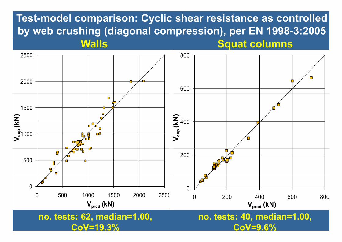
Test-model comparison: Cyclic shear resistance as controlled by web crushing (diagonal compression), per EN 1998-3:2005
Squat columnsWalls2500 800
2000600
1500
N)
400N)
1000
V exp
(k 400
V exp
(k
500200
00 500 1000 1500 2000 2500
V (kN)
00 200 400 600 800
V (kN)
no. tests: 62, median=1.00, CoV=19.3%
no. tests: 40, median=1.00, CoV=9.6%
Vpred (kN) Vpred (kN)

FRP FRP Jackets per EN1998Jackets per EN1998--3:20053:2005

Experimental DatabaseExperimental Database4 Range and mean values of parameters in the tests of4. Range and mean values of parameters in the tests of
FRP-jacketed rectangular columns in the databaseParameter 219 columns with continuous bars (145
with CFRP, 24 with GFRP, 27 with AFRP and 23 with other composite)
45 columns with lap-spliced bars (42 with CFRP, 3 with GFRP) p ) , )
min-max mean min-max mean effective depth, d (mm) 170-720 296 180-720 393 shear-span-to-depth ratio L /h 1-7 4 3 55 2-6 6 4 5shear span to depth ratio, Ls/h 1 7.4 3.55 2 6.6 4.5 concrete strength, fc (MPa) 10.6-90 31.8 11.7-55 31 vertical bar yield stress, fy (MPa) 295-816 431 331-617 492 stirrup yield stress f (MPa) 200 750 388 280 535 442stirrup yield stress, fyw (MPa) 200-750 388 280-535 442 axial-load-ratio, N/Acfc 0-0.85 0.255 0-0.4 0.143 transverse steel ratio, w (%) 0-1.18 0.24 0-0.445 0.212
0 81 6 2 08 0 81 3 9 1 88total vertical steel ratio, tot (%) 0.815-7.6 2.08 0.815-3.9 1.88 geometric ratio of FRP, ρf (%) 0.01-5.31 0.605 0.13-7.5 1.04 nominal FRP strength (MPa) 113-4830 2755 532-4430 2621 elastic modulus of FRP, Ef (GPa) 5.8-390 166 17.8-390 184 lapping-to-bar-diameter ratio, lo/db - - 15-45 30.4

FRP-wrapping of plastic hinges in rectangular members with continuous bars per EN 1998-3:2005
• MR, My: Enhanced by FRP jacket (by 9% w.r.to calculated w/o confinement)– EN 1998-3:2005: increase neglected.
• Effective (elastic) stiffness EI : unaffected by FRP; pre damage: 35% drop
p
• Effective (elastic) stiffness EIeff: unaffected by FRP; pre-damage: 35% drop• EN1998-3:2005: Flexure-controlled ultimate chord rotation, θu: Confinement by FRP increases that due to the stirrups by αfρfff e/fc, where: y p y fρf f,e c,
– ρf=2tf/bw : FRP ratio // direction of loading;– ff,e: FRP effective strength:
c
fffu,fu,ffu,fu,ef,
,min7.01;5.0min,min
fρEεf
Eεff
fu,f, Ef : FRP tensile strength & Modulus; εu,f: FRP limit strain. CFRP/AFRP: εu,f=1.5%; GFRP: εu,f=2%FRP confinement effectiveness:
bh
RbRhf
3221
22
– FRP-confinement effectiveness:
bh3b, h: sides of section; R: radius at section corner
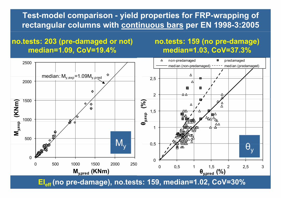
Test-model comparison - yield properties for FRP-wrapping of rectangular columns with continuous bars per EN 1998-3:2005
no.tests: 203 (pre-damaged or not)median=1.09, CoV=19.4%
no.tests: 159 (no pre-damage)median=1.03, CoV=37.3%
2500
median: M =1 09M d
3 non-predamaged predamagedmedian (non-predamaged) median (predamaged)
2000median: My,exp=1.09My,pred
2
2,5
1000
1500
(K
Nm
)
1,5
y,exp
(%
) 500
My,e
xp
0 5
1
θ yθM
00 500 1000 1500 2000 2500
0
0,5
0 0 5 1 1 5 2 2 5 3
θyMy
EIeff (no pre-damage), no.tests: 159, median=1.02, CoV=30%My,pred (KNm)
0 0,5 1 1,5 2 2,5 3θy,pred (%)

Yield properties for FRP-wrapping of the plastic hinge and continuous bars – Biskinis & Fardis 2007, 2013
• Yield moment, My:– Strength of FRP-confined concrete fcc, instead of fc, in section-analysis
for φ M including the calculation of the concrete Elastic Modulus E ;for φy, My, including the calculation of the concrete Elastic Modulus, Ec; – Ec may be estimated per fibMC2010, using fcc instead of fc:
Ec=10000(fcc(MPa))1/3 fabf2
c 0000( cc( a))
– fcc from (widely used) Lam & Teng 2003:c
fuff
y
x
c
cc
ffa
bb
ff ,3.31
fu,f: effective strength of FRP: fu,f=Ef(keffεu,f)Ef: Elastic Modulus of FRP, εu,f: FRP failure strain, k ff: FRP effectiveness factor equal to 0 6 per Lam & Teng
(~same results using other FRP-confinement models: Teng et al 2009, Samaan et al 1998, Bisby et al 2005, Ilki et al 2008, Wang et al 2012)
keff: FRP effectiveness factor, equal to 0.6 per Lam & Teng
• Chord rotation at yielding, θy, effective stiffness, EIeff :– Yield curvature φ calculated with f (as above) & multiplied timesYield curvature φy calculated with fcc (as above) & multiplied times
correction factor 1.06– EIeff = MyLs/3y

Test-model comparison - yield properties for FRP-wrapping of rect. columns with continuous bars per Biskinis & Fardis 2007, 2013
no.tests: 159 (no pre-damage)median=1.01, CoV=37.3%
no.tests: 203 (pre-damaged or not)median=1.06, CoV=19.3%
2000
2500
median: My,exp=1.06My,pred 2.5
3 non-predamaged predamagedmedian (non-predamaged) median (predamaged)
1500
2000
m) 2
%)
1000
xp
(KN
m
1.5
θ y,e
xp
(%
500
My,e
x
0.5
1
θM θ
00 500 1000 1500 2000 2500
( )
00 0.5 1 1.5 2 2.5 3
θ (%)
My θy
EIeff (no pre-damage): no.tests: 159, median=0.99, CoV=30.4%
My,pred (KNm) θy,pred (%)
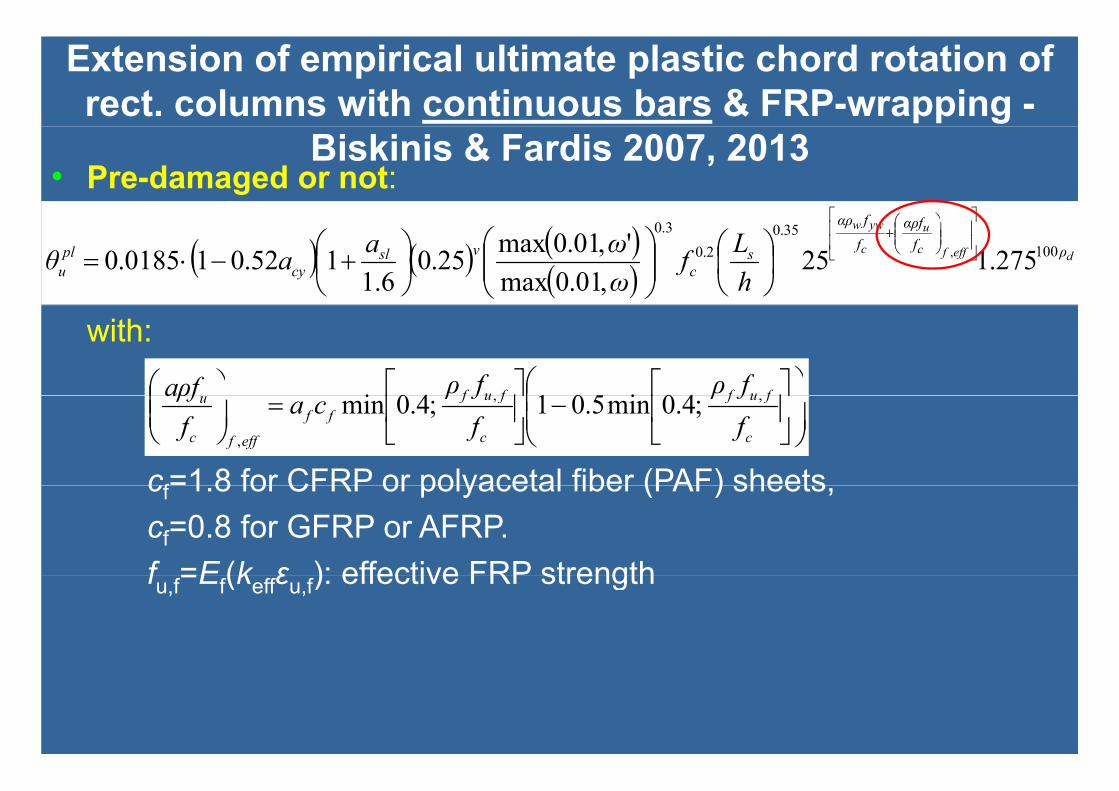
Extension of empirical ultimate plastic chord rotation of rect. columns with continuous bars & FRP-wrapping -
• Pre-damaged or not:f
Biskinis & Fardis 2007, 2013
defffc
u
c
yww
ρffαρ
ffαρ
sc
νslcy
plu h
Lfωωaaθ 100
35.02.0
3.0
275.125,01.0max
',01.0max25.06.1
152.010185.0 ,
with:
fuffuf fρfρfρa 40i50140i
c
fuf
c
fufff
efffc
u
ffρ
ffρ
caffρa ,,
,
;4.0min5.01;4.0min
cf=1 8 for CFRP or polyacetal fiber (PAF) sheetscf 1.8 for CFRP or polyacetal fiber (PAF) sheets, cf=0.8 for GFRP or AFRP.f =E (k ε ): effective FRP strengthfu,f=Ef(keffεu,f): effective FRP strength

Test-model comparison – ultimate cyclic chord rotation for FRP-wrapping of rect. columns with continuous bars: no. tests 128 (pre-damaged or not)
EN 1998 3:2005 v Biskinis & Fardis 2007 2013EN 1998-3:2005
median=1 09 CoV=30 6%Biskinis & Fardis 2013
median=1 025 CoV=30 4%
EN 1998-3:2005 v Biskinis & Fardis 2007, 2013
median=1.09, CoV=30.6% median=1.025, CoV=30.4%25
median (all): θu,exp=1.09θu,pred
25
median (all): θu,exp=1.025θu,pred
20 20
15
exp
(%) 15
exp
(%)
10θ u,e
CFRP jacket
10θ u,e
CFRP jacket5 AFRP jacket
GFRP jacketPAF jacket
5 AFRP jacketGFRP jacketPAF jacket
00 5 10 15 20 25
θu,pred (%)
PAF jacket0
0 5 10 15 20 25θu,pred (%)
PAF jacket

f
Alternative ultimate cyclic chord rotation for continuous bars & FRP-wrapping – per GCSI (KANEPE)
Test-to-predicted ultimate cyclic chord rotation, θu – no.tests: 128,
di 1 75 C V 54 5%
wdc
cc
ff 25.1125.1
FRP l t i ti median=1.75, CoV=54.5%25
ωwd: FRP volumetric ratioα: FRP-confinement effectiveness factor CFRP (adopted here also for
20median (all): θ e p=1 75θ pred
20035.0 ccccu ffCFRP (adopted here also for AFRP and PAF):
215
exp
(%)
θu,exp 1.75θu,pred 2007.0 ccccu ff
fuef ff ,, FRP effective strength:
GFRP:
10θ u,e
CFRP jacket
ψ: reduction factor for number of layers (k); ψ 1 for k<4
5
jAFRP jacketGFRP jacketPAF jacket
41 k for k≥4ψ=1 for k<4
00 5 10 15 20 25
θu pred (%)
PAF jacket
32 φδy
uθ μμ
θθμ

FRP-wrapped rectangular members with ribbed bars lap-splicedover length lo in the plastic hinge: EN 1998-3:2005 & other options
• EN 1998-3:2005:1. Both bars in pair of lapped compression bars count as compression steel.2. For the yield properties (My, y , θy), the stress fs of tension bars is:
fs=fy(lo/loy,min), if lo< loy,min=(0.2fy/√fc)db (fy, fc in MPa), loy,min: one-third shorter th ith t FRPthan without FRP.
3. Ultimate chord rotationθ = +pl (l /l ) if l < l = d f /[(1 05+14 5 ρ f )√f ]θu=y+pl
u(lo/lou,min), if lo < lou,min = dbfy/[(1.05+14.5 αlρf ff,e)√fc],– fc: MPa, ρf=2tf/bw: FRP ratio // loading, ff,e: effect. FRP strength (MPa), – α = α (4/n ) (n : total lap-spliced bars; only the 4 corner bars restrained)– αl = αf(4/ntot) (ntot: total lap-spliced bars; only the 4 corner bars restrained).
• Or, Eligehausen & Lettow 2007 for fibMC2010:20251
1.03/12.025.055.0
db fkKccflf
ffffhl EtnkAnk1
• cd = min[a/2; c1; c] ≥ db , cd ≤ 3db
,)20;max(
2020
2.51 maxytr
db
d
b
c
b
bs fkK
cc
dc
mmdf
dlf
s
ffff
h
shls
bbtr E
Etnks
Ankdn
kK 1
d [ ; 1; ] b , d b
• cmax = max[α/2; c1; c] ≤ 5db
• fy, fc in MPa

Test-model comparison - Yield properties for FRP-wrapping of rect. columns with bars lap-spliced over length lo per EN1998-3:2005, no.tests 45
My: median=1.075, CoV=10.5% θy: median=1.075, CoV=17.7%
1750
2000
median: My,exp=1.075y,pred 1.75
2median: θy,exp=1.075θy,pred
1500
1750
1 25
1.5
1000
1250
(KN
m)
1
1.25
exp
(%
) 500
750
My,e
xp
0.5
0.75θ y,
0
250
0
0.25
0 0 25 0 5 0 75 1 1 25 1 5 1 75 2
My θy
0 250 500 750 1000 1250 1500 1750 2000
My,pred (KNm)0 0.25 0.5 0.75 1 1.25 1.5 1.75 2
θy,pred (%)

Test-model comparison - yield properties of FRP-wrapped circular
l ith l li d b4000
5000
median: My,exp=My,pred
columns with lap-spliced bars per EN1998-3:2005 (Biskinis & Fardis 2007, 2013)
3000
(KN
m)
2013)
1000
2000
My,e
xp
(
Myno tests: 42
no.tests: 42median=1.00
C V 15 2%0
0 1000 2000 3000 4000 5000
Mypred (KNm)
no.tests: 42median=0.98
CoV=22%
CoV=15.2%
1 5
2
median θ 0 98θ800
1000y,pred ( )CoV 22%
1
1,5
xp
(%)
median:θy,exp=0.98θy,pred
600
xp(M
Nm
2 ) EIeff
0,5
θ y,e
x
200
400
(MyL
s/3θ y
) ex
median:(MyLs/3θy)exp=0 96(MyLs/3θy)pred
θy
no.tests: 42median=0.96
00 0,5 1 1,5 2
θy,pred (%)
00 200 400 600 800 1000
(MyLs/3θy)pred (MNm2)
(MyLs/3θy)exp 0.96(MyLs/3θy)pred
CoV=22.2%

Extension of empirical ultimate plastic chord rotation forrectangular members with lap-spliced bars & FRP-wrapping –
• Required lapping for no adverse effect of lap-splice on ultimate deformationfd
Biskinis & Fardis 2007, 2013
u
ybou
ffρa
fdl
2min,
25.1405.1
with:
c
efffctension
ffn
,
5.1405.1
fuffufu fρfρfρa 40i50140iwith:
f =E (k ε )
c
fuf
c
fufff
efffc
u
ffρ
ffρ
caffρ ,,
,
;4.0min5.01;4.0min
fu,f=Ef(keffεu,f)ntension: number of lapped bars on tension side of section
,i
min 1,pl plouu lap
ll
• If lo<lou,min, θupl is reduced as:
,minoul • (αρfu/fc )f,eff neglected in θu
pl if 2/ntension≤0.5

Test-model comparison – ultimate cyclic chord rotation of FRP-wrapped ofrectangular columns w/ lap-spliced bars, no.tests 44 (pre-damaged or not)
EN1998-3:2005 v Biskinis & Fardis 2007 2013
EN 1998-3:2005median=0 89 CoV=36 3%
Biskinis & Fardis 2013median=1 005 CoV=23 2%
EN1998-3:2005 v Biskinis & Fardis 2007, 2013
median=0.89, CoV=36.3% median=1.005, CoV=23.2%12
median: θu,exp=0.885θu,pred
12median: θu,exp=1.005θu,pred
8
10, p ,p
8
10
6
8
xp
(%)
6
8
xp
(%)
4θu,
ex
4θu,
ex
0
2
0
2
00 2 4 6 8 10 12
θu,pred (%)
00 2 4 6 8 10 12
θu,pred (%)

Extension of ultimate plastic chord rotation model with curvatures and plastic hinge length to circular columns with
l li d b & FRP i Bi ki i & F di 2013
slipuslsplplyuyu aLLL 5.01)( ubLslipu d 5.5,
lap-spliced bars & FRP-wrapping – Biskinis & Fardis 2013
Lpl, fcc, εcu as in members (FRP-wrapped or not) with continuous bars
slipuslsplplyuyu ,)( ubLslipu ,
6Steel strain at ultimate deformation of member depends on lap length, if lo< l i : f
5
6
median:θu,exp=0.97θu,pred
lou,min:
s
y
oy
osu
ou
olsu E
fl
ll
l
min,min,, 2.02.1
4
%)
with: ccyhsh
ybL minou,
fffa
fdl
/665
2
3
θ u,e
xp
(% ccyhsh fff
1
2
Test-to-prediction ratio, no.tests: 37 median=0.97, CoV=38.6%
00 1 2 3 4 5 6
θu pred (%)

Cyclic shear resistance of FRP-wrapped rectangular members as controlled by diagonal tension, per EN1998-3:2005
• Vf=min(εu fEu f, fu f)ρf bwz/2 : FRP-contribution to cyclic shear resistance:
fwccs
totpl
ccs
R VVAfhLfAN
LxhV
,5min16.01)100,5.0max(16.0,5min05.0155.0,min
2
f ( u,f u,f, u,f)ρf w y• ρf :FRP ratio, ρf = 2tf/bw;• fu,f:FRP tensile strength.
V b f t ib ti f b t l (b b idth i t l t l ti )• Vw=ρwbwzfyw: contribution of web steel (bw: web width, z: int. lever arm; ρw: steel ratio)• ρtot: total longitudinal steel ratio• h: section depth 1 2
1,4p
• x : depth of compression zone• Ac= bwd
0,8
1
1,2
V u,p
red
Test-to-prediction ratio vs μ, no. tests 12median=0.99, CoV=14.8%:
0,4
0,6
V u,e
xp /V
,
0
0,2
0 0,5 1 1,5 2 2,5 3 3,5 4 4,5 5d tilit
• In a FRP-retrofitted member the shear resistance as controlled by diagonal tension cannot exceed the shear resistance of old member as controlled by web crushing
ductility

RC jackets per EN1998RC jackets per EN1998--3:20053:2005

Concrete Jackets (continued/anchored in joint; w/ or w/o lap splices in old member)Calculation assumptions:
F ll it ti f j k t & ld t d (j k t d b• Full composite action of jacket & old concrete assumed (jacketed member: monolithic”), even for minimal shear connection at interface (roughened interface,steel dowels epoxied into old concrete: useful but not essential);
• f of “monolithic member”= that of the jacket (avoid large differences in old & new f )• fc of monolithic member = that of the jacket (avoid large differences in old & new fc)• Axial load considered to act on full, composite section;• Longitudinal reinforcement of jacketed column: mainly that of the jacket. Vertical
bars of old column considered at actual location between tension & compressionbars of old column considered at actual location between tension & compression bars of composite member (~ “web” longitudinal reinforcement), with its own fy;
• Only the transverse reinforcement of the jacket is considered for confinement;• For shear resistance the old transverse reinforcement taken into account only in• For shear resistance, the old transverse reinforcement taken into account only in
walls, if anchored in the (new) boundary elements• The detailing & any lap-splicing of jacket reinforcement are taken into account.Then:Then: MR & My of jacketed member: ~100% of θy of jacketed member for pre-yield (elastic) stiffness: ~105% of Sh i t f j k t d b 100% f Shear resistance of jacketed member: ~100% of Flexure-controlled ultimate deformation θu: ~100% ofthose of “monolithic member” calculated w/ assumptions above.pIf jacket bars are not continued/anchored in the joint:The jacket is considered only to confine fully the old column section.

54 jacketed members w/ or w/o lap splices: test-to-calculated as monolithic1.2
1.6
1.8
0.8
1
M y,c
alc
1
1.2
1.4
y,Eq
.(1)&
(2)
0.4
0.6
M y,e
xp /
M
continuous bars plain15dblaps deformed15dblaps 0 4
0.6
0.8
θ y,e
xp / θ
y
0
0.2
continuous bars plain 15db laps deformed 15db laps
plain 25db laps deformed 30db laps deformed 45db laps
non-anchored jacket bars group average st. dev. of group mean
My
0
0.2
0.4
θy
2.5 1.6
1.75
2
2.25
1.2
1.4
(3) )
1
1.25
1.5
EI ex
p / E
I* eff
06
0.8
1
/ ( θ
*y + θ
uplEq
.(
0.25
0.5
0.75
EIeff0.2
0.4
0.6θ u
,exp
θu
a: no treatment, b: no treatment, predamage, c: welded U-bars, d: dowels, e: roughened, f: roughened / predamage, g: U-bars+ roughened, h: U-bars+roughened / predamage, i: roughened+dowels, j: roughened+dowels / predamage
0a b c d e f g h i j k
0a b c d e f g h i j

Steel jackets per EN1998Steel jackets per EN1998--3:20053:2005

J k t t b f th j i t ( l t j i t f )
Steel Jackets (not continued/anchored in joint)
Jacket stops before the joint (several mm gap to joint face)• Flexural resistance, pre-yield (elastic) stiffness & flexure-
controlled ultimate deformation of RC member is not enhanced by jacket (flexural deformation capacity ~same asi ld b i id j k t b fit f fi t)in old member inside jacket, no benefit from confinement);
• 50% of shear resistance of steel jacket, Vj=Ajfyjh, can be j j yjrelied upon for shear resistance of retrofitted member (suppression of shear failure before or after flexural
)yielding);• Lap-splice clamping via friction mechanism at jacket-
member interface, if jacket extends to ~1.5 times splice length and is bolt-anchored to member at end of splice region & ~1/3 its height from the joint face (anchor bolts at third-point of side)