Embed Size (px)
Citation preview
PLEXSYS proprietary rights are included in the information disclosed herein. Recipient by accepting this document agrees that neither this document nor the information disclosed herein nor any part thereof shall be reproduced or transferred to other documents or used or disclosed to others for any other purpose except as specifically authorized in writing by PLEXSYS.
Modeling and
Simulation Training ASCOT | PLEXComm | sonomarc
A d v a n c e d S i m u l a t i o n C o m b a t O p e r a t i o n s T r a i n e r

_____________________________________________________________________________________________________ PLEXSYS proprietary rights are included in the information disclosed herein. Recipient by accepting this document agrees that neither this document nor the information disclosed herein nor any part thereof shall be reproduced or transferred to other documents or used or disclosed to others for any other purpose except as specifically authorized in writing by PLEXSYS.
2
TABLE OF CONTENTS
Purpose .................................................................................................................................... 3
1 ASCOT ................................................................................................................................. 3
Overview ..................................................................................................................... 3
Internal and DMO Training ......................................................................................... 3
Interoperability and Configuration ............................................................................. 3
Ease of Use in Training ................................................................................................ 4
Scenario Creation ........................................................................................................ 4
Scenario Realism ......................................................................................................... 5
Entity Management .................................................................................................... 6
Automated Features ................................................................................................... 6
Electronic Attack ......................................................................................................... 7
Flexibility ..................................................................................................................... 7
System Performance ................................................................................................... 7
Maps and Visual Displays ............................................................................................ 7
Data Link ..................................................................................................................... 9
Common RADAR Application (CRA) .......................................................................... 10
2 Communications Simulation ........................................................................................... 11
3 Competitor Comparison .................................................................................................. 12
4 Additional Information .................................................................................................... 12
Test Certifications ..................................................................................................... 12
APPENDIX A – ACRONYMS .................................................................................................... 13
TABLE OF FIGURES
Figure 1: ................................................................................................................................... 4
Figure 2: ................................................................................................................................. 4
Figure 3: ................................................................................................................................. 5
Figure 4: ................................................................................................................................. 5
Figure 5: ................................................................................................................................. 8
Figure 6: ................................................................................................................................... 8
Figure 7: ................................................................................................................................... 9
Figure 8: ................................................................................................................................. 10

_____________________________________________________________________________________________________ PLEXSYS proprietary rights are included in the information disclosed herein. Recipient by accepting this document agrees that neither this document nor the information disclosed herein nor any part thereof shall be reproduced or transferred to other documents or used or disclosed to others for any other purpose except as specifically authorized in writing by PLEXSYS.
3
PURPOSE This white paper provides a description of the features and benefits of the PLEXSYS developed modeling
and simulation training solutions through the use of the Advanced Simulation Combat Operations
Trainer (ASCOT) and PLEXSYS Communication (PLEXComm and sonomarc) products. This proposal
highlights the unique capability of these PLEXSYS solutions to enhance a customer’s ability to replicate
any contingency by providing a “near-real world” training environment.
1 ASCOT
OVERVIEW The Advanced Simulation Combat Operations
Trainer (ASCOT) is a high fidelity simulation
system that is used to create the environment
necessary to facilitate training for today’s
modern simulators. It is the backbone of the
U.S. AWACS Mission Training Centers and
multiple other simulation systems used both in
military and civilian applications. The system is
scalable and can be networked together in a
single site configuration of multiple ASCOTs or
through multiple sites world-wide. ASCOT
provides radar modeling, scenario creation,
exercise generation, data-link messaging
capability, data link translation, and dynamic
simulation entity play. The ASCOT Instructor
Operator Station (IOS) provides the instructor
full control of each entity’s weapons, sensor, IFF
and data link.
INTERNAL AND DMO TRAINING For internal training, ASCOT allows weapons,
surveillance and data link operators to train in
small team, full mission crews or individually. In
a netted exercise, ASCOT provides scenario
management through a server/client
configuration, allowing for centralized control
of large force exercises. Multiple ATOs/ACOs
can be converted, merged and time
synchronized to be played out as a single
exercise, or individual tracks/formations can be
driven by one or more operators facilitating any
configuration of training. ASCOT operates on
multiple military networks including the CAF
DMON, ARCNet and JTEN, allowing for
participation in numerous DMO and joint
training events.
INTEROPERABILITY AND CONFIGURATION The ASCOT supports both DIS (Version 7, to
include backwards compatible with versions 4,
5 and 6) and HLA 1.3 (MAK/NG Pro/Pitch RTIs)
to interact with other simulation platforms. It is
capable of directly interfacing with an array of
operational equipment including off-the-shelf
radar trackers and Data-Link gateways. ASCOT
produces a realistic Radar/IFF picture on an
operational display, supports multi-level
security networks, and is run-time configurable
for most DIS/HLA simulation management
parametrics.

_____________________________________________________________________________________________________ PLEXSYS proprietary rights are included in the information disclosed herein. Recipient by accepting this document agrees that neither this document nor the information disclosed herein nor any part thereof shall be reproduced or transferred to other documents or used or disclosed to others for any other purpose except as specifically authorized in writing by PLEXSYS.
4
EASE OF USE IN TRAINING ASCOT is an extremely intuitive tool for scenario
creation and dynamic simulation driving. It
enables any driver regardless of experience,
“ease of use”, ensuring realistic and meaningful
scenario creation and entity management,
facilitating the ability to replicate a real world
environment. Help screens for commands,
easily assessable features, data entry fields and
a mission script player for queuing of voice calls
from any simulated platform or agency are
available. Training an ASCOT user to run
intercepts can be accomplished in under one
hour and within just a few days; operators can
develop complicated large-force exercises, and
be proficient with these features:
Database Development
Scenario Creation
Scenario Execution
Data-Link Simulation
Communications Simulation
Features that exemplify the ease of use are the
ability to create and manipulate entities after
exercise start in ASCOT Tabular Display (TD) or
drive the entity from ASCOT Map. Entity
characteristics can be changed through the
command area in ASCOT Tabular Display, with
the keyboard or on ASCOT Map by using
modern GUIs and mouse clicks. Track options
allow the operator to change color of track IDs
and data link, vector stick lengths, entity size
(S/M/L), and entity data block information. By
selecting an entity on ASCOT Map, engagement
rings of any emitting entity can be turned
on/off and weapons can be employed
automatically allowing the operator to make
timely/realistic inputs into the simulation
environment. The “moving map” feature in
ASCOT Map enables the driver to keep
situational awareness of a specific entity by
maintaining the selected track in the center of
the map display until disabled. Any driver can
easily view ASCOT Map in 3D or the “God’s-eye-
view” quickly enhancing awareness of the 21st
century synthetic battlespace ASCOT produces.
Figure 1: ASCOT TD: Provides current data on all scenario entities and is one of two places to manipulate entity; heading, alt, speed, weapons, Link and other entity information
Figure 2: ASCOT Map: Gives “God’s eye” or 3D view of the battle space; track manipulation via entity command; and operator viewing of entity radar parameters, engagement lines and missile fly-out
SCENARIO CREATION Scenario creation and management are
facilitated through the use of ATO Exercise
_____________________________________________________________________________________________________ PLEXSYS proprietary rights are included in the information disclosed herein. Recipient by accepting this document agrees that neither this document nor the information disclosed herein nor any part thereof shall be reproduced or transferred to other documents or used or disclosed to others for any other purpose except as specifically authorized in writing by PLEXSYS.
5
Generation (ATOXGEN), PLEXComm Scripted
Voice Player (SVP), ASCOT Editor (ED) and
ASCOT Map, allowing scenarios to be created
through the use of USMTF or ADAP formatted
ATO/ACO or dynamically through operator
input. ASCOT ED is utilized for creating and
merging scenario files quickly, along with Data-
Link participant and message scripting to
provide training for the entire mission crew.
ASCOT ED also has the capability to play out the
scenario in advance at real-time or accelerated
speeds providing operators an overview of the
mission.
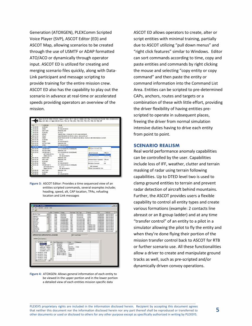
Figure 3: ASCOT Editor: Provides a time sequenced view of an entities scripted commands, several examples include; heading, speed, alt, CAP location, TPAs, refueling location and Link messages
Figure 4: ATOXGEN: Allows general information of each entity to be viewed in the upper portion and in the lower portion a detailed view of each entities mission specific data
ASCOT ED allows operators to create, alter or
script entities with minimal training, partially
due to ASCOT utilizing “pull down menus” and
“right click features” similar to Windows. Editor
can sort commands according to time, copy and
paste entities and commands by right clicking
the mouse and selecting “copy entity or copy
command” and then paste the entity or
command information into the Command List
Area. Entities can be scripted to pre-determined
CAPs, anchors, routes and targets or a
combination of these with little effort, providing
the driver flexibility of having entities pre-
scripted to operate in subsequent places,
freeing the driver from normal simulation
intensive duties having to drive each entity
from point to point.
SCENARIO REALISM Real world performance anomaly capabilities
can be controlled by the user. Capabilities
include loss of IFF, weather, clutter and terrain
masking of radar using terrain following
capabilities. Up to DTED level two is used to
clamp ground entities to terrain and prevent
radar detection of aircraft behind mountains.
Further, the ASCOT provides users a flexible
capability to control all entity types and create
various formations (example: 2 contacts line
abreast or an 8 group ladder) and at any time
“transfer control” of an entity to a pilot in a
simulator allowing the pilot to fly the entity and
when they’re done flying their portion of the
mission transfer control back to ASCOT for RTB
or further scenario use. All these functionalities
allow a driver to create and manipulate ground
tracks as well, such as pre-scripted and/or
dynamically driven convoy operations.

_____________________________________________________________________________________________________ PLEXSYS proprietary rights are included in the information disclosed herein. Recipient by accepting this document agrees that neither this document nor the information disclosed herein nor any part thereof shall be reproduced or transferred to other documents or used or disclosed to others for any other purpose except as specifically authorized in writing by PLEXSYS.
6
ENTITY MANAGEMENT Any pre-programmed track can be converted
and driven dynamically. Entities include; air,
ground, surface, sub-surface, life forms and
cultural features, which can be used to simulate
almost any type of real-world operation. One or
more tracks can be “strapped” to a lead entity
and driven via the lead entity only or separately
when needed. Formations can be created and
entities can be repositioned anywhere in the
scenario within seconds. During refueling
scenarios operator-definable orbits and anchors
can be created and fuel states update
automatically when aircraft refuel. CAP and CP
locations can be created dynamically and re-
used. Entity emitters and IFF can be
manipulated and fire control window displays
can be viewed displaying remaining weapons
load-out and a list of radar contacts in the
entities emitter.
AUTOMATED FEATURES Automated RTB, take-off / landing profiles
to/from airbases are used to simulate airbase
activities. Engaging and firing on opposing
forces is facilitated through either automatic or
manual modes. Tallying of all entity kills,
damage and misses is automatically kept track
of within the system. The Smart Entity feature
uses an ROE-based decision matrix to decide to
engage an enemy or not. When the decision is
made to engage, the entity will fire weapons
automatically. Temporary Flight Restriction
areas (TFRs) can be created to simulate FAA
“no-fly zones” and aircraft will automatically
clear and avoid the area, all takeoff and
landings are suspended while the TFR is active.
Auto FDL will allow an entity to utilize
“intelligent entity behavior” to make decisions
when receiving various FDL orders in
determining whether the entity can carry the
order out and “WILCO” the order or “CANTCO”
the order.
PLEXSYS has made significant advancements in
the area of ground environment automation.
Integrated Air Defenses or IADS features allow
the ability to create a network that contains
early warning radar sites and SAM sites
consisting of an Integrated Command and
Control (ICC) element and the fire support units
(FSU). These units work together to track and
engage threats automatically while generating
the appropriate Data-Link messages when
designated a friendly Participating Unit. Off
road movement for ground entities uses terrain
data to affect entity movement with the entity
becoming aware of water and prompting the
user to continue or not. If a road route crosses a
body of water, then it is inferred that there is a
bridge for the entities to cross. The entity will
also use terrain to slow down or speed up when
going up and down hills/mountains. The
Mount/Dismount feature enables ASCOT life
forms to “mount” or climb into vehicles and
“dismount” or climb out of vehicles. The
Improvised Explosive Devices (IED) feature
allows the user to place IEDs within the “play
area” and detonate them based on time or on
command (detonation can also occur due to
enemy proximity).
Side Affiliation is another automated feature
that assists in scenario execution of a large
force exercise. This feature allows the user to
apply rules to groups of entities that will
employ ROE-based decision making to decide to
engage another group. Groups A can have a
friendly relationship with group B, a neutral
relationship with group C and a hostile
relationship with group D. SIDES can be defined
in any manner regardless of DIS IDs. Postures
_____________________________________________________________________________________________________ PLEXSYS proprietary rights are included in the information disclosed herein. Recipient by accepting this document agrees that neither this document nor the information disclosed herein nor any part thereof shall be reproduced or transferred to other documents or used or disclosed to others for any other purpose except as specifically authorized in writing by PLEXSYS.
7
can then be set creating conditions between
sides overriding limitations based on DIS
relationships (this side is friend with that side
but hostile to that other side). Along with
hostile postures, you can set an auto-fire
condition to initiate an engagement between
two entities set to appropriate sides. An
example would be to have two DIS friendly
ground units engage one another via auto-fire,
simply by putting one on an opposite side to the
other and setting their postures to "enemy" and
auto-fire "on."
The PLEXCOMM Scripted Voice Player (SVP)
integrates with ASCOT and provides the ability
to pre-record specific radio calls to be played
back automatically at a specified time, or
manually during a scenario. The radio
transmission can be a one-time call, repeated,
or looped as many times as needed. SVP allows
the user to create, review and script an
unlimited number of playback radio events
prior to an exercise for use. This would allow
the scenario planner to include pre-scripted
calls from any entity necessary at any time. SVP
supports IEEE standards for simulation of radios
to include radio encoding, simulated secure
crypto and simulated Have Quick transmissions.
This is another of many features PLEXSYS offers
its customers that reduces time and effort
required during a demanding exercise, and
allows the user to focus on other exercise
responsibilities, while reducing white force
assets required for exercise support.
ELECTRONIC ATTACK ASCOT has a robust Electronic Attack (EA)
simulation capability that provides realism for
scenario planners. This capability can be
scripted for automatic execution or
accomplished dynamically as the scenario
unfolds. EA feature include Radar Jamming, GPS
Jamming and Link-16 Jamming. These feature
use common simulation protocol messaging
allowing ASCOT to stimulate other protocol
compliant systems.
FLEXIBILITY Flexibility is the key to any entity generator and
the ASCOT exemplifies “flexibility”. Database
driven applications allow greater flexibility and
autonomy for operators and the system can be
deployed to any location and only requires
110/240 VAC 50/60 Hz power to operate.
Ultimately, there is also no limit to the number
of ASCOT stations within a LAN or WAN and
entity display block and track block data can be
customized to suit each operator in the ASCOT
tabular display.
SYSTEM PERFORMANCE Over 35,000 smart entities per exercise can be
generated by ASCOT, providing a robust
capability to any training environment. ASCOT
can simultaneously generate high fidelity air,
surface, ground, or subsurface entities using a
3.0 GHz Intel Xeon; faster CPU speeds enable
even more entities to be generated. ASCOT is
compatible with all versions of Windows from
2000 to Windows 7.
MAPS AND VISUAL DISPLAYS ASCOT utilizes CADRG Maps for real-world
visual references within any theater including:
GNC/JNC/ONC/TPC/JOG/TLM 100/TLM
50/CIB1/CIB 10/CIB 5/FIF/VMap. ASCOT Map
displays terrain images from aerial
photography, satellites, or it can use any image
or graphic as background including the ability to
load and display any number of DAFIF data map
layers. Situational displays can be tailored for
viewing both truth and data-link pictures
_____________________________________________________________________________________________________ PLEXSYS proprietary rights are included in the information disclosed herein. Recipient by accepting this document agrees that neither this document nor the information disclosed herein nor any part thereof shall be reproduced or transferred to other documents or used or disclosed to others for any other purpose except as specifically authorized in writing by PLEXSYS.
8
including a 3D visual display of both detection
and engagement cones and being able to view
engagement lines and weapons fly-out. ASCOT
Map can be quickly offset to any part of the
world, allowing for rapid adjustment of the play
area. Entity movement from ASCOT Map is
made easy through pull down menus and right
clicks options such as take over, fire weapons,
heading/altitude/speed changes, reposition and
sending entities to scenario points such as CAPs,
Orbits and Targets.
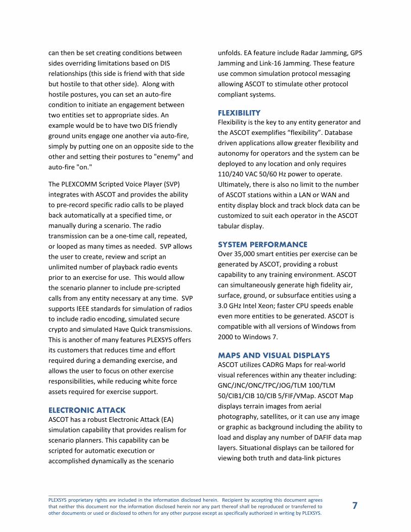
Figure 5: ASCOT Map using Global Navigation Chart (GNC) map
Figure 6: ASCOT Map using Operational Navigation Chart (ONC) map
_____________________________________________________________________________________________________ PLEXSYS proprietary rights are included in the information disclosed herein. Recipient by accepting this document agrees that neither this document nor the information disclosed herein nor any part thereof shall be reproduced or transferred to other documents or used or disclosed to others for any other purpose except as specifically authorized in writing by PLEXSYS.
9
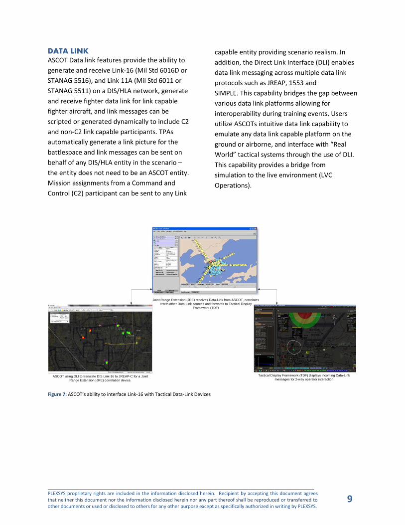
DATA LINK ASCOT Data link features provide the ability to
generate and receive Link-16 (Mil Std 6016D or
STANAG 5516), and Link 11A (Mil Std 6011 or
STANAG 5511) on a DIS/HLA network, generate
and receive fighter data link for link capable
fighter aircraft, and link messages can be
scripted or generated dynamically to include C2
and non-C2 link capable participants. TPAs
automatically generate a link picture for the
battlespace and link messages can be sent on
behalf of any DIS/HLA entity in the scenario –
the entity does not need to be an ASCOT entity.
Mission assignments from a Command and
Control (C2) participant can be sent to any Link
capable entity providing scenario realism. In
addition, the Direct Link Interface (DLI) enables
data link messaging across multiple data link
protocols such as JREAP, 1553 and
SIMPLE. This capability bridges the gap between
various data link platforms allowing for
interoperability during training events. Users
utilize ASCOTs intuitive data link capability to
emulate any data link capable platform on the
ground or airborne, and interface with “Real
World” tactical systems through the use of DLI.
This capability provides a bridge from
simulation to the live environment (LVC
Operations).
Joint Range Extension (JRE) receives Data-Link from ASCOT, correlates
it with other Data-Link sources and forwards to Tactical Display
Framework (TDF)
Tactical Display Framework (TDF) displays incoming Data-Link
messages for 2-way operator interactionASCOT using DLI to translate DIS Link-16 to JREAP-C for a Joint
Range Extension )JRE) correlation device.
Figure 7: ASCOT’s ability to interface Link-16 with Tactical Data-Link Devices

_____________________________________________________________________________________________________ PLEXSYS proprietary rights are included in the information disclosed herein. Recipient by accepting this document agrees that neither this document nor the information disclosed herein nor any part thereof shall be reproduced or transferred to other documents or used or disclosed to others for any other purpose except as specifically authorized in writing by PLEXSYS.
10
COMMON RADAR APPLICATION (CRA) CRA along with ASCOT TD has the ability to
simulate real world radars by sending SGF 1.1
NUNIO, CD2SIS or ASTERIX radar data to a COTS
trackers like MSCT or ProCon. The radar is
modeled within ASCOT and based on the
radar’s detection capability which includes
terrain masking, radar range, along with target
Radar Cross Section (RCS), CD2 radar messages
are sent from the CRA to the tracker. There is
no restriction to the number of radars CRA can
process to be fed into the tracker, no different
than if the tracker was deployed and receiving
Patriot, FAA or joint service radar data (TPS-59)
externally. The CRA also allows for receiving
radar data from live radars for display in ASCOT.
This allows the user to control live aircraft from
the U.S. AWACS Mission Training Centers.
ASCOT models the radar parameters and sends messages to CRA for
radar plot generation. Radar plots are displayed on tactical scope, just as if it came from a
“live” Radar”
CRA creates radar plots based on ASCOT calculations and sends plot
messages to tactical tracker.
Figure 8: ASCOTs ability to use CRA to interface with tactical systems
_____________________________________________________________________________________________________ PLEXSYS proprietary rights are included in the information disclosed herein. Recipient by accepting this document agrees that neither this document nor the information disclosed herein nor any part thereof shall be reproduced or transferred to other documents or used or disclosed to others for any other purpose except as specifically authorized in writing by PLEXSYS.
11
2 COMMUNICATIONS SIMULATION The PLEXSYS line of communications hardware
and software includes both PLEXComm and
sonomarc. Sonomarc is the latest offering from
PLEXSYS. It was designed for high fidelity,
server-based radio modeling use in today’s
modern simulation systems. Sonomarc provides
environmental audio for cockpit and other
applications as well as a remote control feature
that allows for integration with onboard
simulation system radio controls, just like the
actual live systems. Sonomarc also offers an
instructor interface that provides monitoring of
student audio, switch actions and allows for
private conversations between the instructor
and student. The instructor can inject simulated
jamming for student training as well as terrain
for Line-Of-Site (LOS) calculations. Sonomarc
radios can be attached to the own-ship entity as
well as constructive scenario players to provide
the positioning for these LOS calculations as
propagation loss calculations based on modeled
radio types. Sonomarc supports the simulation
of a secure crypto system allowing the operator
to set HQ Net and ToD and WoD each radio.
The instructor has visual cues when
transmitting in a simulated secure and
simulated HQ mode and can send a simulated
“Mickey” allowing them to further replicate real
world capabilities.
Analog to digital conversion is also made
possible with sonomarc, providing the interface
between simulation communication and tactical
radio systems. This is made possible by the
sonomarc Live Virtual Constructive (LVC)
module that not only accomplishes the analog
to digital conversion but is also capable of
generating a contact closure or voltage key to
PTT actual radio systems. In return, LVC can
accept the same contact closure or voltage to
PTT its internal DIS or HLA radios.
PLEXCommVR is a lite weight, stand-alone
Windows or Linus OS compatible software
application that is capable of modeling
HF/UHF/VHF/SATCOM radios using DIS or HLA
protocols. PLEXCommVR models radios much
like sonomarc and can simulate loss of
reception using entity attachment for LOS and
propagation loss calculations. The number of
radios and nets can be specifically tailored to
the customer’s needs and each radio can be
runtime configurable for most DIS parametrics
allowing the operator to adjust; frequency,
power, gain, modulation and exercise ID.
PLEXCommVR is an excellent low cost
alternative for stand-alone applications.
_____________________________________________________________________________________________________ PLEXSYS proprietary rights are included in the information disclosed herein. Recipient by accepting this document agrees that neither this document nor the information disclosed herein nor any part thereof shall be reproduced or transferred to other documents or used or disclosed to others for any other purpose except as specifically authorized in writing by PLEXSYS.
12
3 COMPETITOR COMPARISON PLEXSYS simulation tools have many advantages
over our competitors. In addition to a superior
product, PLEXSYS has unmatched customer
service. Below are bullets that highlight the
advantages PLEXSYS products have over the
competitors:
ASCOT produces 35,000+ entities, a number
that would not be possible with other
environment generators (EG).
ASCOT is fully USAF CAF DMO Compliant
and Certified. It is used within the CAF DMO
Federate as a system that new players to
the DMON need to prove integration with
before they can join the DMON.
ASCOT has the most robust data-link
capabilities of any EG. Capabilities include
Link 16 (j series messages MIL STD and
STANAG), Link 11 (STANAG 5511 m-series
messages and our own TADIL J Hybrid called
JoverA), and IJMS (NATO standard)
ASCOT is much more flexible in terms of
scenario scripting and execution. Scenario
development is accomplished in hours
where it takes other EGs weeks.
ASCOT is database driven and user are
provided with databases that can be
manipulated without having to come back
to PLEXSYS to add entity type, weapons,
emitters and other scenario items. PLEXSYS
provides and database tool called SDMT
that allows for database changes without
being familiar with the database program or
structure.
ASCOT provides quick and easy entity
creation
ASCOT has a very robust ground movement
capability
4 ADDITIONAL INFORMATION
TEST CERTIFICATIONS The ASCOT was certified to operate in the Joint
Training Environment (JTE) by the US Joint
Forces Command (USJFCOM) Tactical
Development and Innovation Branch (TDIB) on
behalf of the Joint National Training Capability
(JNTC) Joint Management Office (JMO) on 26
May 2009. During that certification the ASCOT
was connect to the Northrop Grumman
Network Operations Center (NOC) and the
Distributed Operations Training Center (DTOC)
in Des Moines, IA as part of the certification.
_____________________________________________________________________________________________________ PLEXSYS proprietary rights are included in the information disclosed herein. Recipient by accepting this document agrees that neither this document nor the information disclosed herein nor any part thereof shall be reproduced or transferred to other documents or used or disclosed to others for any other purpose except as specifically authorized in writing by PLEXSYS.
13
APPENDIX A – ACRONYMS ASCOT Advanced Simulation Combat
Operations Trainer
ATO Air Tasking Order
AWACS Airborne Warning and Control System
ACO Airspace Control Order
ADAP Automated Downlink of Airborne
Parameters
CAP Combat Air Patrol
CAS Close Air Support
COTS Commercial Off-The-Shelf
CP Contact Point
CRA Common Radar Application
DLI Data Link Interface
DTED Digital Terrain Evaluation Data
DAFIF Digital Aeronautical Flight Information
File
DVR Digital Video Recorder
DIS Distributed Interactive Simulation
FAA Federal Aviation Administration
FST-J Fleet Synthetic Training-Joint
GNC Global Navigation Chart
HQ Have Quick
HLA High Level Architecture
IFF Identification Friend or Foe
IOS Instructor Operator Station
JNC Joint Navigation Chart
JOG Joint Operations Graphic
JRE Joint Range Extension
JREAP Joint Range Extension Application
Protocol
LAN Local Area Network
MISTEX MACCS Integrated Simulation Training
Exercise
MSCT Multiple Source Correlation Tracker
MAK (Company that produces a High
Performance version of RTI)
NG Pro (Raytheon RTI product that enables the
use of HLA)
ONC Operational Navigation Chart
OPLAN Operational Plan
ProCon Radar Protocol Converter
RTI Run-Time Infrastructure
SDMT Scenario Data Management Tool
SIMPLE Standard Interface for Multiple
Platform Link Evaluation
SIF Selective Identification Feature
TFR Temporary Flight Restriction (area)
TLM Topographic Line Map (NIMA)
TPC Tactical Pilotage Chart
USMTF United States Message Text Format


![0HWKRGVIRU0HGLXP VL]HG 7HUULWRULDO&DUQLYRUHV˛ - … · Inventory Fundamentals No. 1 [Forms] (previously referred to as the Dataform Appendix). This is important to ensure compatibility](https://img.dokumen.tips/doc/110x75/5d5c91d688c99397058b9706/0hwkrgviru0hglxp-vlhg-7huulwruldoduqlyruhv-inventory-fundamentals-no.jpg)


