Embed Size (px)
Citation preview

Visionscape® I-PAK® HE User Manual
83-100016-02
Rev 3.7.4, Sept. 2011
Copyright and DisclaimerCopyright ©2011 by Microscan Systems, Inc.700 S.W. 39th Street, Renton, WA, U.S.A. 98057(425) 226-5700 FAX: (425) 226-8682
All rights reserved. The information contained herein is proprietary and is provided solely for the purpose of allowing customers to operate and/or service Microscan manufactured equipment and is not to be released, reproduced, or used for any other purpose without written permission of Microscan.
Throughout this manual, trademarked names might be used. Rather than place a trademark (™) symbol at every occurrence of a trademarked name, we state herein that we are using the names only in an editorial fashion, and to the benefit of the trademark owner, with no intention of infringement.
DisclaimerThe information and specifications described in this manual are subject to change without notice.
Latest Manual VersionFor the latest version of this manual, see the Download Center on our web site at: www.microscan.com.
Technical SupportFor technical support, email: [email protected].
Microscan Systems, Inc.700 S.W. 39th StreetRenton, WA 98057U.S.A.Tel: 425 226 5700Fax: 425 226 [email protected]
Microscan EuropeTel: 31 172 423360Fax: 31 172 423366
Microscan Asia PacificR.O. Tel: 65 6846 1214Fax: 65 6846 4641
Microscan Limited Warranty Statement and Exclusions
What Is Covered?Microscan Systems Inc. warrants to the original purchaser that products manufactured by it will be free from defects in material and workmanship under normal use and service for a period of one year from the date of shipment. This warranty is specifically limited to, at Microscan’s sole option, repair or replacement with a functionally equivalent unit and return without charge for service or return freight.
What Is Excluded?This limited warranty specifically excludes the following: (1) Any products or parts that have been subject to misuse, neglect, accident, unauthorized repair, improper installation, or abnormal conditions or operations; (2) Any products or parts that have been transferred by the original purchaser; (3) Customer mis-adjustment of settings contrary to the procedure described in the Microscan Systems Inc. owners manual; (4) Upgrading software versions at customer request unless required to meet specifications in effect at the time of purchase; (5) Units returned and found to have no failure will be excluded; (6) Claims for damage in transit are to be directed to the freight carrier upon receipt. Any use of the product is at purchaser’s own risk. This limited warranty is the only warranty provided by Microscan Systems Inc. regarding the product. Except for the limited warranty above, the product is provided “as is.” To the maximum extent

permitted by law, this express warranty excludes all other warranties, express or implied, including but not limited to, implied warranties of merchantability and. Technical support questions may be directed to: [email protected] Register your product with Microscan: www.microscan.com/register fitness for a particular purpose. Microscan Systems Inc. does not warrant that the functions contained in the product will meet any requirements or needs purchaser may have, or that the product will operate error free, or in an uninterrupted fashion, or that any defects or errors in the product will be corrected, or that the product is compatible with any particular machinery.
Limitation of LiabilityIn no event shall Microscan Systems Inc. be liable to you or any third party for any special, incidental, or consequential damages (including, without limitation, indirect, special, punitive, or exemplary damages for loss of business, loss of profits, business interruption, or loss of business information), whether in contract, tort, or otherwise, even if Microscan Systems Inc. has been advised of the possibility of such damages. Microscan Systems Inc.’s aggregate liability with respect to its obligations under this warranty or otherwise with respect to the product and documentation or otherwise shall not exceed the amount paid by you for the product and documentation. Some jurisdictions do not allow the exclusion or limitation of incidental or consequential damages or limitations on an implied warranty, so the above limitation or exclusion may not apply to you. This warranty gives you specific legal rights, and you may also have other rights which may vary from state to state.
Tel: 425.226.5700 | Fax: 425.226.8250 | [email protected]


Contents
PREFACE Welcome! xvii
Purpose of This Manual xviiManual Conventions xviiValidation xvii
Development Details xviii
21 CFR Part 11 xviiiOn the CD xviiiRelated Documentation xix
Visionscape® I-PAK HE Documentation xixVisionscape® Documentation xix
CHAPTER 1 Visionscape® I-PAK® HE Inspection 1-1
System Specifications 1-2Minimum PC Requirements 1-2HawkEye 1600T Communications 1-2
Product Specifications 1-3Functional Specifications 1-4Touch Input Software 1-6Configurations with PCs 1-6
Recommended Configurations with PCs 1-6
Supported Camera 1-7User Interface 1-7Storing Inspection Results 1-7
Visionscape® I-Pak® HE User Manual v
Contents
Moving & Sizing Tools 1-7A Visionscape® I-PAK® HE Product 1-8
Scan for Sequence Steps Using Outputs 1-9
Software Systems 1-9I-PAK HE Start-up Procedure (Typical) 1-10
Running I-PAK HE for the First Time 1-11
I-PAK HE Shutdown Procedure 1-13
CHAPTER 2 Visionscape® I-PAK HE Tutorials 2-1
Setup Mode & Run Mode 2-2Tutorial 1 — OCVFontless Tool 2-3Tutorial 2 — OCVRuntimeTool 2-20
Setting Up the Tool Set 2-20Font Training 2-32OCVRuntimeTool Training 2-36
What’s Next 2-42
CHAPTER 3 21 CFR Part 11 3-1
Components 3-1Access Levels 3-2Enabling 21 CFR Part 11 3-3The I-PAK Administrator 3-4Customer Responsibilities 3-5
Starting I-PAK HE, Using Part 11 & Adding I-PAK HE Users 3-6
21 CFR Part 11 Functions 3-7End of Batch Reports 3-7
Create PDFs 3-9Print 3-10Archive PDFs 3-11Reset Audit Trail 3-12
Reconciliation of Configuration Files 3-12Configure 21 CFR Part 11 Users 3-13
vi Visionscape® I-Pak® HE User Manual

Contents
Common 21 CFR Part 11 Areas of Concern 3-19How do I activate 21 CFR Part 11? 3-19What are the Password Schemes & Restrictions? 3-19How can I prevent my users from getting to the desktop? 3-20How safe is the Audit Trail from being compromised? 3-20How safe are the Jobs files from being compromised? 3-21How safe are the Configuration & Statistics files from being compromised? 3-21Can this data be saved to a non-editable format? 3-21How do I know who made the last batch or change? 3-21My company wants the number of login failures to be 3 but I-PAK HE defaults to 5. What can I do? 3-21If I get an alarm on I-PAK HE, how will I know someone saw it? 3-22What is the date format used inside the Part 11 files? 3-22All this writing to disk; what if I-PAK HE runs out of hard drive space? 3-22
CHAPTER 4 Automatic Identification 4-1
Barcode Reading 4-1Other Steps Used 4-1Theory of Operation 4-1Description 4-2Settings 4-5Training 4-13Results 4-14I/O Summary 4-16
Data Matrix Tool 4-18Other Steps Used 4-18Theory of Operation 4-18Description 4-20Settings 4-23Training 4-32Results 4-34Print Verification Types 4-35
AIM 4-35ISO 4-37IAQG 4-38DPM 4-39
I/O Summary 4-40DMR Verification 4-42
Visionscape® I-Pak® HE User Manual vii

Contents
DMR Step Output Datums 4-42DMR Step Output Datums 4-42VerifyDetails 4-43
OCRTrainableFont Tool 4-49Theory of Operation 4-50OCR Font Training 4-56
Numeric View 4-67Character-Related Features 4-68
Show Character Array & Show StdDev Array 4-69Show Histogram & Show Font Histogram 4-69Delete Training & Remove from Font 4-71
Training Tips 4-71Tips for Marking OCR Fonts 4-72
Results 4-72
CHAPTER 5 OCV Reference 5-1
Overview 5-1OCV Inspection 5-1
Additional Filters 5-3Brief Descriptions 5-3
Custom Properties — Create/Modify OCVFonts 5-5Custom Settings 5-6Main Custom Properties Dialog Box 5-7
Buttons 5-7Font Manager Dialog Box 5-9
Buttons 5-9Training Fonts 5-10Training the OCVFont Tool 5-12Remove Symbol Dialog 5-15Automatic Font Selection & Scaling Dialog 5-15
Buttons 5-16Automatic Font Selection — The AutoFont Button 5-16
Choosing a Symbol 5-17Positioning the OCVFont Shape 5-17Performing the Automatic Font Selection & Scaling 5-18
Font Scaling — The Scale Button 5-19Choosing a Symbol 5-20Positioning the OCVFont Shape 5-20Performing the Font Scaling 5-20
viii Visionscape® I-Pak® HE User Manual

Contents
OCVFont 5-21Creating FontSymbols 5-21OCVFont Tab 5-23LayoutStep Tab 5-24AutoThreshold Tab 5-25ComputePolarity Tab 5-26DefaultSymb Tab 5-27
FontSymbol 5-27AutoFind 5-35
Training 5-36
OCVFont Tool 5-37Training 5-37Inspection 5-37Step Tip 5-43
OCVRuntimeTool 5-45Training 5-46Inspection 5-46Step Tips 5-52
OCVFontless Tool 5-55Training 5-55Inspection 5-55Step Tips 5-65OCVSymbolStep 5-67
Substitute/Ignore 5-75Character Substitution 5-77Ignoring a Character 5-78Finishing Up 5-78
Keyboard Input of Match String 5-78Enabling Keyboard Input of Match String 5-78OCVFont Tool & OCVRuntimeTool Training 5-79Keyboard Input Protocol 5-82
Inspection String Protocol 5-82
External Input of Match String 5-82Enabling External Input of Match String 5-82External Input of Match String Checkbox 5-83Match String Mismatch Action 5-84Transmit Final Layout String 5-84OCVFont Tool & OCVRuntimeTool Training 5-84Transmit Final Inspection String 5-88External Input of Match String Protocol 5-89
Visionscape® I-Pak® HE User Manual ix
Contents
Header Line Protocol 5-89Input Line Protocol 5-89Input & Output Inspection String Protocol 5-89Transmit Final Layout String Protocol 5-89
Lot ChangeOver — CHANGELAYOUT Command 5-90Setup Notes & Precautions 5-90RS-232 Input of Layout String 5-90
RS-232 CHANGELAYOUT Usage 5-90RS-232 CHANGELAYOUT Syntax 5-91
I-PAK HE User Interface 5-92RS-232 ChangeLayout Error Debug 5-94RS-232 ChangeLayout Success Response 5-96
ChangeLayout Debug 5-97RS-232 ChangeLayout Error Messages 5-98
Ethernet Input of Layout String 5-99Ethernet CHANGELAYOUT Usage 5-99Ethernet CHANGELAYOUT Syntax 5-99
I-PAK HE User Interface 5-100Ethernet ChangeLayout Error Debug 5-100Ethernet ChangeLayout Success Response 5-102
ChangeLayout Debug 5-103Ethernet ChangeLayout Error Messages 5-104
OCV Tips 5-105OCVFont 5-105
Layout Step 5-105DefaultSymbol 5-105
OCVRuntimeTool 5-105Layout Step 5-106
Converting Jobs with Embedded OCVFonts 5-106
Troubleshooting 5-107Training Font Based Tools – Read Match% 5-107
The Behavior 5-108The Explanation 5-108
Training 5-108Correct Character Training 5-108Automatic Segmenting Character Training 5-108Example with Automatic Segment 5-109Example with Manually Trained Characters 5-109
Conclusions 5-110
x Visionscape® I-Pak® HE User Manual

Contents
CHAPTER 6 Setup Mode Reference 6-1
Overview 6-1Setup Mode Menus 6-3
File Menu 6-3Access Level Menu 6-421 CFR Part 11 Menu 6-6Calibration Menu 6-6Image Menu 6-7Help Menu 6-8
Change Product 6-10Change Lot Feature 6-11Location of Jobs Folder 6-14
Automatic Backup of Jobs 6-14Archiving & Restoring Products 6-14
Setting Archival Pathname 6-14Job Archive Dialog Box 6-14Archiving OCVFonts 6-16
Train and Tryout 6-17AutoStep or Wizard Training Method 6-18
Image 6-18Job View 6-18Completing AutoStep Mode 6-19
AutoStep Off 6-19Train and Tryout Mode 6-19Train and Tryout Toolbar 6-19
AutoStep 6-20Train 6-20Previous 6-20Next 6-20Next Camera 6-20Tool Settings 6-21Options 6-21Acquire 6-22Live 6-23Zoom In 6-23Zoom Out 6-23Try Tool 6-23Try All 6-24Custom Settings 6-24
Visionscape® I-Pak® HE User Manual xi

Contents
Exit Training to Main Setup 6-24Automatically Setting Tool Settings 6-25Special Training of Tools 6-25
Match String 6-25Training Match String Enabled Tools 6-25
Data Matrix Tool Wildcard Match Character 6-26Match String Fields & Buttons 6-26
Masking Tool 6-31
Statistics & Data 6-32Clear Statistics 6-32Save Stats File 6-33Save Config File 6-33Save Images 6-33Transmit Statistics 6-36Preview Config File 6-39Preview Statistics 6-40OCV Tracking 6-40Close Statistics 6-42
Advanced Settings 6-42Create A Product 6-43
Program Settings Dialog Boxes 6-43System Settings Dialog Boxes 6-45Step Program Dialog Boxes 6-47Special Features of Tools & Steps in Job Creation 6-50Inspection Steps Without Snapshots 6-52
Product Creation 6-52Train and Tryout 6-53Run Mode 6-53I/O 6-53
Continue Product Creation by Training the Tools 6-53Save Product 6-54Product Settings 6-56
Cameras Tab 6-56Data Valid Tab 6-58I/O Tab 6-58
System Settings 6-62System Settings — Communication Tab 6-63
Selection 6-63Configure 6-63
System Settings — Training and Results Tab 6-71Product ChangeOver Activities 6-71
xii Visionscape® I-Pak® HE User Manual
Contents
Results Reporting 6-74Training 6-84OCV Training 6-86
System Settings — General Tab 6-90Job Settings 6-91End Batch 6-9121 CFR Part 11 Configuration 6-91Menu Settings 6-94I-PAK HE Windows Settings 6-94Config File Format 6-95I-PAK HE System Name 6-95
Edit Tool Set 6-95Tool Settings 6-96Windows Explorer 6-97Close Advanced 6-98
Run Mode 6-98Troubleshooting 6-98
Memory Limitations on the HawkEye 1600T 6-98Shutting Down I-PAK HE 6-98
CHAPTER 7 Run Mode Reference 7-1
Overview 7-1Run Mode Window 7-2
Run Mode Buttons & Border 7-2Camera Results 7-6Runtime Change Lot 7-9
Password — 21 CFR Part 11 Access 7-9Password — Standard Access 7-9Change Lot Dialog Box 7-9
Overruns 7-12Exiting Run Mode & Entering Setup Mode 7-13Default Passwords 7-13Forgotten Passwords 7-14
Forgotten Passwords — 21 CFR Part 11 7-14
End Batch 7-15
Visionscape® I-Pak® HE User Manual xiii
Contents
APPENDIX A Installation & Software A-1
Minimum PC Requirements A-1Tested PCs A-2I-PAK HE Components A-2Installing the Software A-3
Installing the Visionscape® Software A-3Installing the Visionscape® I-PAK HE Software A-4
Software Upgrades — 21 CFR Part 11 Usage A-5Uninstalling I-PAK HE Software A-5Starting the I-PAK HE Program A-5UPS & UPS Software A-6
Configuring the UPS Software A-7
CD-RW Support A-15Windows XP A-15Windows 2000 A-15
APPENDIX B Connecting Smart Cameras to a PC B-1
Connecting Smart Cameras to a PC using Static IP Addresses & a Network Switch B-1
Connecting a PC & Smart Cameras to an Ethernet Switch B-1Setting the PC to Use a Static IP Address B-2Setting the Smart Cameras to Use Static IP Addresses B-4Verifying the Setup Using the Network Browser B-12
APPENDIX C Demo Mode C-1
Copying Job, Font, & Image Files C-1Check Jobs Before Running Demo Mode C-2Demo Mode Jobs C-3Enabling Demo Mode C-3Running in Demo Mode C-5Disabling Demo Mode C-5
xiv Visionscape® I-Pak® HE User Manual
Contents
APPENDIX D Perl Gems: Tips & Techniques D-1
I-PAK HE Custom Step & CustomVision Tool D-1Properties Pages D-1Custom Step D-2
none D-2FailCode D-3
Settings D-5Results D-5
Custom Vision Tool D-5none D-6Cylinder_UnWarp D-7
Theory of Operation D-7Cylinder Unwrap ROI D-7Using the Cylinder Unwrap Warp D-7Description D-9Settings D-9Training D-10Results D-10I/O Summary D-10
Dynamic_Binarize D-10Theory of Operation D-10Using Dynamic_Binarize D-10Description D-12Settings D-13Results D-13
FailCode D-14FindRotated D-14
Using FindRotated D-14Description D-16Settings D-17Results D-17
Index Index-1
Visionscape® I-Pak® HE User Manual xv

Contents
xvi Visionscape® I-Pak® HE User Manual
Preface
PREFACE Welcome!
Purpose of This ManualThis Visionscape® I-PAK® HE User Manual provides a foundation for successful I-PAK HE operation. It guides you to apply I-PAK HE vision tools for training and inspection.
IMPORTANT: The diagrams in this manual may contain a different version number than this release but the functionality remains the same.
Manual ConventionsThe following typographical conventions are used throughout this manual.
• Items emphasizing important information are bolded.
• Menu selections, menu items and entries in screen images are indicated as: Run (triggered), Modify..., etc.
ValidationVisionscape® I-PAK® HE is intended to be the product of choice in the pharmaceutical industry. Microscan has designed the product with just this in mind. To best support the pharmaceutical industry, we know we must be able to provide you with our software development processes. Any software that has to do with production equipment in the pharmaceutical industry is mandated by the FDA to be validated. You may choose to perform your own application
Visionscape® I-PAK® HE User Manual xvii
Preface
validation. We can provide you with our software development details describing how the software is created and tested.
21 CFR Part 11Visionscape® I-PAK® HE is 21 CFR Part 11 technically compliant. Login user names and passwords are set up by the I-PAK Administrator.
The Part 11 user names, their encrypted passwords, and the original time/datestamp when a user was created or last changed his or her password are stored in a data file called ipak.usr.
When you upgrade the I-PAK HE software, you must manually move the ipak.usr data file to the current version of I-PAK HE.
See Chapter 3, “21 CFR Part 11,” for complete information regarding 21 CFR Part 11.
On the CDThe CD contains the following:
• Visionscape® I-PAK® HE V3.7.4.
• Visionscape® V3.7.4.
• Visionscape® I-PAK® HE User Manual — This manual is in PDF format in the I-Pak_HE folder. Double-click Visionscape I-PAK HE 374 User Manual.pdf to view the manual.
• Visionscape® documentation set.
• Visionscape VSKit programmers documentation and sample applications.
• Adobe Reader V8.12 install
xviii Visionscape® I-PAK® HE User Manual
T)
Related DocumentationAll Visionscape® documentation is provided on the CD in PDF format. The PDFs are located in the \Vscape\Documentation folder. You need Adobe Acrobat Reader (included on the CD) to open the PDF. Double-click any .PDF to open Acrobat and view a manual.
Visionscape® I-PAK HE Documentation
• Visionscape® I-PAK® HE V3.7.4 User Manual (this manual)
• Visionscape® I-PAK® HE V3.7.4 ReadMe
Visionscape® Documentation
• Getting Started With VS-1 Smart Camera (VS-1 also called the HawkEye 1600
• VS-1 Smart Camera Guide (VS-1 also called the HawkEye 1600T)
• Visionscape® Tools Reference
• Perl Script Custom Tool Programmer's Manual
• Visionscape® V3.7.4 ReadMe
Visionscape® I-Pak® HE User Manual xix

Preface
xx Visionscape® I-PAK® HE User Manual

1
Vis
ion
scap
e® I-
PAK
®
HE
Insp
ecti
on
1
CHAPTER 1 Visionscape® I-PAK® HE Inspection
Visionscape® I-PAK® HE’s primary focus is to inspect, measure, verify position, verify characters, and detect flaws on pharmaceutical packaging. The implementation of I-PAK HE is flexible, allowing for expansion of I-PAK HE into the other vision areas of pharmaceutical companies, i.e., medical device manufacturing, diagnostic drugs, glass vials, and laboratory automation. I-PAK HE is adaptive and can be used easily in many other industries.
Note: You can use the IntelliFind™ geometric pattern mark tool if you purchased a HawkEye 1600TIS or 1600TIH. For more information about IntelliFind™, see Chapter 7 of the Visionscape® Tools Reference (on your CD in PDF format).
Visionscape® I-Pak® HE User Manual 1-1
Chapter 1 Visionscape® I-PAK® HE Inspection
System SpecificationsI-PAK HE supports up to four HawkEye 1600T Smart Cameras connected to a Windows PC. Ensure that you review carefully the PC and network requirements below.
Minimum PC Requirements
• Pentium 4, 2.4 GHz or higher or Pentium 4, 1.66 GHz Core 2 Duo or higher
• Minimum of 1GB memory
• VGA display adapter – 64K or true color
• Microsoft Windows 2000 SP4 or Microsoft Windows XP SP2 or later
Note: We recommend you connect the HawkEye 1600T Smart Camera to the PC using dedicated network cards and static IP addresses to minimize problems with disconnections. Refer to Appendix B, “Connecting Smart Cameras to a PC,” for a description of how to configure your PC and HawkEye Smart Cameras to talk to each other via static IP addresses.
HawkEye 1600T CommunicationsEach Smart Camera acts as an asynchronous processing engine. In other words, each Smart Camera contains its own processor and IO architecture and is, therefore, able to capture images, process those images, and send results (via IO, RS-232, or Ethernet) independent of the PC and of the other Smart Cameras. Each Smart Camera is fully independent.
Communications between the I-PAK HE user interface and the HawkEye 1600T are conducted via TCP/IP. I-PAK HE provides communication to external processors via Digital IO, TCP/IP and RS-232.
1-2 Visionscape® I-Pak® HE User Manual

Vis
ion
scap
e® I-
PAK
®
HE
Insp
ecti
on
1
1CHAPTER 1 Visionscape® I-PAK® HE Inspection
Visionscape® I-PAK® HE’s primary focus is to inspect, measure, verify position, verify characters, and detect flaws on pharmaceutical packaging. The implementation of I-PAK HE is flexible, allowing for expansion of I-PAK HE into the other vision areas of pharmaceutical companies, i.e., medical device manufacturing, diagnostic drugs, glass vials, and laboratory automation. I-PAK HE is adaptive and can be used easily in many other industries.
Note: You can use the IntelliFind™ geometric pattern mark tool if you purchased a HawkEye 1600TIS or 1600TIH. For more information about IntelliFind™, see Chapter 7 of the Visionscape® Tools Reference (on your CD in PDF format).
Visionscape® I-Pak® HE User Manual 1-1
Chapter 1 Visionscape® I-PAK® HE Inspection
Functional SpecificationsI-PAK HE resides on the PC in the Windows environment. It is designed to create, manipulate, train, and execute vision tools via a user-friendly program. I-PAK HE supports both Setup Mode (see Chapter 6, “Setup Mode Reference”) and Run Mode (see Chapter 7, “Run Mode Reference”) in a tri-level access scheme.
Note: I-PAK HE supports Windows 2000 SP4 and Windows XP SP2.
The following is a summary of the I-PAK HE functional specifications:
• Inspection Program Creation
– Acquiring images for the purpose of testing and setting up your vision inspections.
– Selecting, positioning, and sizing the regions of interest (ROI) for each vision tool.
– Training vision tools.
– Entering a match string for a Data Matrix, Barcode Tool, Font Tool or OCRTrainable Font Tool.
– Specifying a font style for training of the Font Tool.
– Adjusting vision inspection properties.
– Saving and restoring Inspection Program (Job) definitions. These are also referred to as “Products”.
• Test Inspection Program in Tryout Mode
– Setting tryout inspection criteria.
– Performing a tryout inspection on a single vision tool or on all vision tools within a Job.
– Modifying inspection criteria to retool tryout results.
1-4 Visionscape® I-Pak® HE User Manual

Functional Specifications
Vis
ion
scap
e® I-
PAK
®
HE
Insp
ecti
on
1
• Product ChangeOver
– Quick restoration of pre-programmed Job definitions for ease of batch changeover.
– Automated resetting of Statistics.
– Connecting to the Smart Camera and downloading an I-PAK HE program to the Smart Camera.
• Viewing of the executing inspections in runtime
– Automatic uploading of inspection images and their results from the Smart Camera to I-PAK HE.
– Showing all camera views of product being inspected.
– Displaying Runtime Graphics of vision tools.
– Zooming in and out on inspection images being displayed.
– Updating the video display to show the last inspection failure with its graphics.
– Viewing of the Failure Report of ongoing inspection noting all the failure types and their frequency for this inspection run.
• End of Batch Statistical and Failure information about the inspection
– On-Screen reviewing of Runtime Statistics and Failures.
– Transmitting of Runtime Statistics via RS-232 or TCP/IP to another device.
– Ability to save Runtime Statistics to a file.
– Resetting of Statistical Information.
• End of Batch Product Data
– On-Screen reviewing of Product Data.
– Transmitting of Product Data via RS-232 or TCP/IP to another device.
– Ability to save the Product definition and Runtime Statistics to a file.
Visionscape® I-Pak® HE User Manual 1-5
Chapter 1 Visionscape® I-PAK® HE Inspection
• Customizing of System Settings
– Ability to set camera triggering method, etc.
– Ability to define automated functions after Product ChangeOver.
• Support of 21 CFR Part 11 Compliance
– Login User Name Access with Password Expiration Feature.
– Configuration File Audit Trail.
– Login option available when retraining a Data Matrix or Barcode Tool in Match Mode and Training a Font Tool or Runtime Font Tool.
Touch Input SoftwareYou can open the Touch Input software using the following button:
The button is only available in dialog boxes where you can enter data. Additionally, in Setup Mode, you can open the Touch Input using Help > Open Softkeyboard.
Configurations with PCs
Recommended Configurations with PCsThe following PCs have been completely tested with I-PAK HE Version 3.7.4:
• IPC 847B Rack, 1.66 GHz Intel Dual core T5500, 2GB
• IPC 627 Box, 2 GHz Pentium M, 1GB
• IPC 677 Panel, 2 GHz Pentium M, 1GB
Note: Neither the Box PC 840 nor the Rack PC 840 V2 are supported by Visionscape V3.7.4 or I-PAK HE V3.7.4.
1-6 Visionscape® I-Pak® HE User Manual
Supported Camera
Vis
ion
scap
e® I-
PAK
®
HE
Insp
ecti
on
1
Supported CameraI-PAK HE supports all models of the HawkEye 1600T Smart Camera, including Hi-Res models, and those that support the IntelliFind™ tool. I-PAK HE V3.7.4 supports up to four HawkEye 1600T Smart Cameras (one inspection and one snapshot per Smart Camera).
User InterfaceThe UI is English only, and independent of the language setting of the operating system.
Storing Inspection ResultsYou can store inspection results to a file. If the file does not exist when you store inspection results, it will be created. If the file does exist, inspection results are appended to the end of the file.
Note: Only Programmers and Supervisors can edit or select a file name.
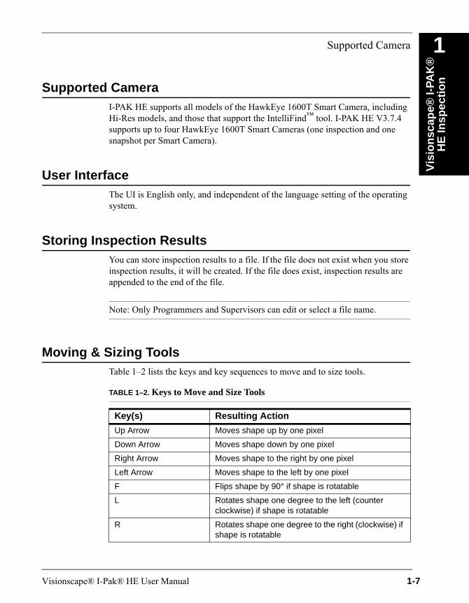
Moving & Sizing ToolsTable 1–2 lists the keys and key sequences to move and to size tools.
TABLE 1–2. Keys to Move and Size Tools
Key(s) Resulting Action
Up Arrow Moves shape up by one pixel
Down Arrow Moves shape down by one pixel
Right Arrow Moves shape to the right by one pixel
Left Arrow Moves shape to the left by one pixel
F Flips shape by 90° if shape is rotatable
L Rotates shape one degree to the left (counter clockwise) if shape is rotatable
R Rotates shape one degree to the right (clockwise) if shape is rotatable
Visionscape® I-Pak® HE User Manual 1-7

Chapter 1 Visionscape® I-PAK® HE Inspection
A Visionscape® I-PAK® HE ProductIn the Visionscape® I-PAK® HE user interface, a combination of tools and steps written to accomplish a particular inspection on a give product is referred to as a “Product” or “Job”.
These product definitions are stored on the PC’s hard drive in a subdirectory where you installed I-PAK HE software called “\Jobs”. For example, if you install the I-PAK HE software in C:\Vscape, then, when you first run I-PAK HE, it automatically creates the Jobs folder as follows:
C:\Vscape\I-Pak_HE\Jobs
I-PAK HE software performs special functions to make using the Visionscape® device easier. In the case of Font Tools and Data Matrix Tools, where many users are often interested in verifying the inspection strings just read, I-PAK HE automatically adds steps to your Job to get this information out of the Visionscape device and on to the PC user interface.
Shift + Up Arrow Increases the height of the shape by one pixel
Shift + Down Arrow Decreases the height of the shape by one pixel
Shift + Right Arrow Increases the width of the shape by one pixel
Shift + Left Arrow Decreases the width of the shape by one pixel
Control + Up Arrow Moves shape up by one tenth of a pixel
Control + Down Arrow Moves shape down by one tenth of a pixel
Control + Right Arrow Moves shape to the right by one tenth of a pixel
Control + Left Arrow Moves shape to the left by one tenth of a pixel
Control + F Flips shape by 180° if shape is rotatable
Control + L Rotates shape one tenth of a degree to the left (counter clockwise) if shape is rotatable
Control + R Rotates shape one tenth of a degree to the right (clockwise) if shape is rotatable
Control + 0 Rotates shape to exactly 0°
TABLE 1–2. Keys to Move and Size Tools (continued)
Key(s) Resulting Action
1-8 Visionscape® I-Pak® HE User Manual

Software Systems
Vis
ion
scap
e® I-
PAK
®
HE
Insp
ecti
on
1
Scan for Sequence Steps Using OutputsAnother useful automatic feature of I-PAK HE is “Scan for Sequence Steps Using Outputs”, which checks the logic so that, when a snapshot step fails (e.g., camera unplugged), the outputs used in sequence steps are set to false. This prevents an inspection from passing (when monitoring sequence step outputs) when the snapshot fails.
Software SystemsSoftware Systems simulate actual Visionscape hardware. They support the Load Images from File mode when acquiring images. A Software System can only get and set virtual IO. Jobs that run on a Software System run locally on the PC, using its CPU and memory (much like the Visionscape 0740 and 0800 boards (not supported in this version)). A dongle is required to run Jobs on a Software System fully; otherwise, the Jobs can be loaded or modified and run on a Software System, but they cannot be saved.
Although a software system is capable of loading a Job that was created for any Visionscape Device, in this version of I-PAK HE, the software system simulates a HawkEye 1600T only. Therefore, creating a Job for a Software System is the same as creating a Job for a HawkEye 1600T. A user should be able to create a Job on a notebook PC using a software system for instance, and then transfer that Job to a PC connected to a HawkEye, and load and run that Job with little to no modifications. There are a few points that you should understand, however, when creating Jobs on a software system:
• The Camera Definitions for the HawkEye 1600TS (standard res) and the HawkEye 1600TH (Hi-res) will be the only camera definitions listed. Choose the appropriate camdef that matches the hardware you will be using.
• By default, the Acquire Tool is programmed to Load Images from File, as there is no digitizer available on a Software System (Image List is empty originally and must be populated also). When loaded on a physical device, you must change the Acquire mode to Acquire from Camera to enable acquisition from the device’s CCD sensor.
• Your Job will be created to use physical IO; so, you will not be able to test the IO when running on the software system, as it does not support physical IO. If you wish to test IO, you must change your IO assignments to use Virtual IO, but if you do, remember to change them back to physical when moving your Job to the actual device.
Visionscape® I-Pak® HE User Manual 1-9
Chapter 1 Visionscape® I-PAK® HE Inspection
For complete information about the Acquire and the Vision System step, see Chapter 1 of the Visionscape® Tools Reference (on your CD in PDF format).
I-PAK HE Start-up Procedure (Typical)I-PAK HE starts up and loads the last Product (AVP file) being used from the previous run of I-PAK HE.
Each VisionSystemStep in the Job is queried for its “SystemLastSavedAs” value. This tells the software which Visionscape Devices were being used by the Job the last time it was saved to disk.
Then, I-PAK HE attempts to “discover” each of the devices named in the Job. Smart Cameras broadcast messages on the network every five seconds to announce their presence. The underlying Visionscape architecture receives these messages, and discovers what devices are available on the network. A list is maintained of all the devices that have been discovered, and I-PAK HE checks this list to see if each device in the Job is present.
• If the device is present, I-PAK HE moves to the next stage of the start-up process.
• If the device is not present, a message in the Splash screen tells you that I-PAK HE is waiting for the device to be discovered. Typically, Smart Cameras may not be discovered for up to 5 seconds. Once discovered, I-PAK HE moves to the next stage of the start-up process.
Note: If, after 10 seconds, the device has not been discovered, you will see a dialog box that offers you three choices:
Select a different Device — Clicking this button allows you to connect the VisionSystem Step to a different device. A dialog box is displayed listing the available devices.
Load a Different Product — Clicking this button allows you to load a different product file.
Exit I-PAK HE — Clicking this button exits I-PAK HE.
Once the device is discovered, I-PAK HE must “Take Control” of it. Each Smart Camera has its own User Name and Password that can be used to “Take Control”
1-10 Visionscape® I-Pak® HE User Manual
I-PAK HE Start-up Procedure (Typical)
Vis
ion
scap
e® I-
PAK
®
HE
Insp
ecti
on
1
of the device. Once you have control of a device, you can download Jobs to it, start and stop inspections, etc. Other users are locked out from accessing the device while you have control of it. Each Smart Camera has the following default user name and password:
User Name: hawkeyePassword: vision
I-PAK HE will try to take control using the default user name and password, it will also try to use no user name and password. If these fail, then a dialog box will be displayed, asking you to enter the user name and password. If you enter the correct values, and I-PAK HE is able to take control successfully, these values will be saved so that in the future, it can take control automatically. This means that you don’t need to enter user names and passwords for each device every time you start up and every time you change products.
Note: The user name and password used to take control of the Smart Camera has nothing to do with the user names and passwords used by I-PAK HE itself when using 21 CFR Part 11; do not confuse them.
Once I-PAK HE has discovered and taken control of each of the devices used by the Product, the Job is downloaded to each Smart Camera, all inspections are started, and the I-PAK HE interface goes into Run Mode.
Running I-PAK HE for the First TimeWhen you run I-PAK HE for the first time, you will be prompted to select a Smart Camera, as described above. Then, I-PAK HE will create a sample Job (Sample.avp) for you and download it to the Smart Camera. This is an example, or a sample, of a job you might run at your production plant. This sample job does not use live images from the camera. Instead, it displays an image file (sample.tif) from the PC’s hard drive.
Visionscape® I-Pak® HE User Manual 1-11
Chapter 1 Visionscape® I-PAK® HE Inspection
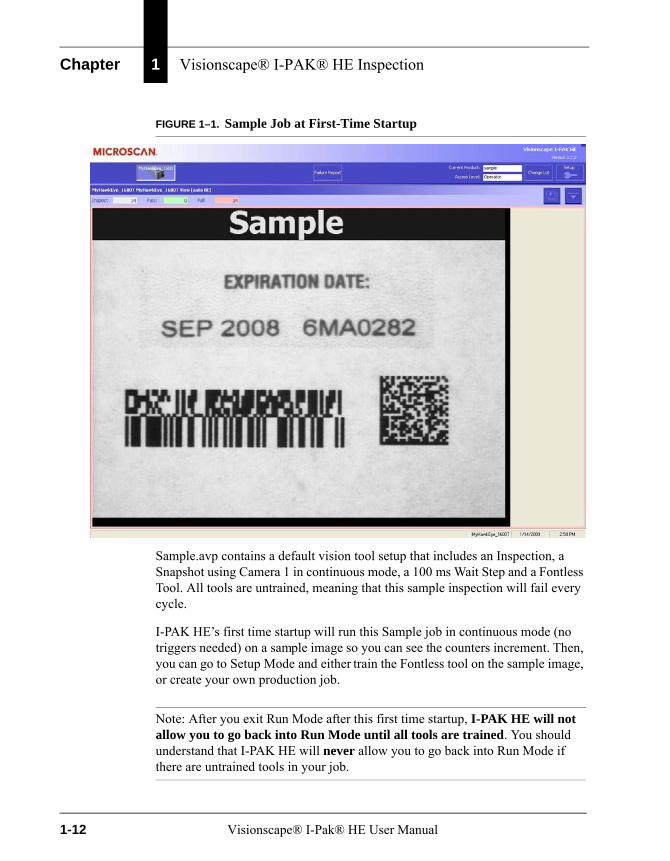
FIGURE 1–1. Sample Job at First-Time Startup
Sample.avp contains a default vision tool setup that includes an Inspection, a Snapshot using Camera 1 in continuous mode, a 100 ms Wait Step and a Fontless Tool. All tools are untrained, meaning that this sample inspection will fail every cycle.
I-PAK HE’s first time startup will run this Sample job in continuous mode (no triggers needed) on a sample image so you can see the counters increment. Then, you can go to Setup Mode and either train the Fontless tool on the sample image, or create your own production job.
Note: After you exit Run Mode after this first time startup, I-PAK HE will not allow you to go back into Run Mode until all tools are trained. You should understand that I-PAK HE will never allow you to go back into Run Mode if there are untrained tools in your job.
1-12 Visionscape® I-Pak® HE User Manual

I-PAK HE Shutdown Procedure
Vis
ion
scap
e® I-
PAK
®
HE
Insp
ecti
on
1
I-PAK HE Shutdown ProcedureTo properly shut down I-PAK HE, exit Run Mode by entering the Programmer password. Then, close I-PAK HE by selecting File > Exit. Next, via the PC’s Start button, shutdown the PC. When the PC has completed shutting down, turn off the UPS (if present).
Visionscape® I-Pak® HE User Manual 1-13

Chapter 1 Visionscape® I-PAK® HE Inspection
1-14 Visionscape® I-Pak® HE User Manual
2
Vis
ion
scap
e® I-
PAK
H
E T
uto
rial
s
2
CHAPTER 2 Visionscape® I-PAK HE Tutorials
This chapter guides you through two tutorials:
• A basic Visionscape® I-PAK® HE tutorial.See “Tutorial 1 — OCVFontless Tool” on page 2-3.
• A more advanced tutorial using font-based Font tools. See “Tutorial 2 — OCVRuntimeTool” on page 2-20.
This chapter serves as a guide. Your results may vary.
Ensure that the HawkEye 1600T Smart Camera and I-PAK HE software have been properly installed and configured (see Appendix A, “Installation & Software,”).
As you go through these tutorials, refer to:
• Chapter 5, “OCV Reference”
• Chapter 6, “Setup Mode Reference”
• Chapter 7, “Run Mode Reference”
Visionscape® I-Pak® HE User Manual 2-1
Chapter 2 Visionscape® I-PAK HE Tutorials
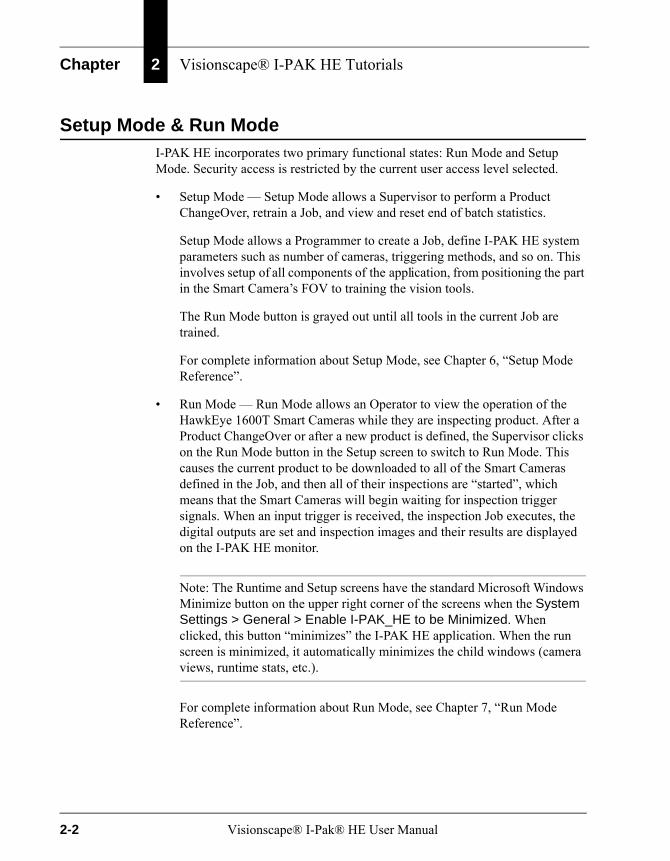
Setup Mode & Run ModeI-PAK HE incorporates two primary functional states: Run Mode and Setup Mode. Security access is restricted by the current user access level selected.
• Setup Mode — Setup Mode allows a Supervisor to perform a Product ChangeOver, retrain a Job, and view and reset end of batch statistics.
Setup Mode allows a Programmer to create a Job, define I-PAK HE system parameters such as number of cameras, triggering methods, and so on. This involves setup of all components of the application, from positioning the part in the Smart Camera’s FOV to training the vision tools.
The Run Mode button is grayed out until all tools in the current Job are trained.
For complete information about Setup Mode, see Chapter 6, “Setup Mode Reference”.
• Run Mode — Run Mode allows an Operator to view the operation of the HawkEye 1600T Smart Cameras while they are inspecting product. After a Product ChangeOver or after a new product is defined, the Supervisor clicks on the Run Mode button in the Setup screen to switch to Run Mode. This causes the current product to be downloaded to all of the Smart Cameras defined in the Job, and then all of their inspections are “started”, which means that the Smart Cameras will begin waiting for inspection trigger signals. When an input trigger is received, the inspection Job executes, the digital outputs are set and inspection images and their results are displayed on the I-PAK HE monitor.
Note: The Runtime and Setup screens have the standard Microsoft Windows Minimize button on the upper right corner of the screens when the System Settings > General > Enable I-PAK_HE to be Minimized. When clicked, this button “minimizes” the I-PAK HE application. When the run screen is minimized, it automatically minimizes the child windows (camera views, runtime stats, etc.).
For complete information about Run Mode, see Chapter 7, “Run Mode Reference”.
2-2 Visionscape® I-Pak® HE User Manual

Tutorial 1 — OCVFontless Tool
Vis
ion
scap
e® I-
PAK
H
E T
uto
rial
s
2
Tutorial 1 — OCVFontless ToolIn this tutorial, you will create a simple I-PAK HE product that uses an OCVFontless Tool. It is assumed that all System Settings are set to their default values. If you have modified any System Settings, the figures and descriptions in this tutorial may vary from the results you experience.
1. From Windows, select Start > Visionscape > Visionscape I-PAK_HE. I-PAK HE displays its Welcome screen, as shown in Figure 2–1.
FIGURE 2–1. Select a Device for I-PAK HE Dialog Box
Note: This screen only comes up the first time you launch I-PAK HE, or if the last loaded product cannot be found.
2. Click OK. I-PAK HE displays the Select a Visionscape Device dialog box, as shown in Figure 2–2.
Visionscape® I-Pak® HE User Manual 2-3

Chapter 2 Visionscape® I-PAK HE Tutorials
FIGURE 2–2. Select a Visionscape Device Dialog Box
3. Select a device. Then, click the Select any Smart Camera... button.
Note: If the Smart Camera is connected directly to a PC (no network involved), I-PAK HE automatically chooses the Smart Camera, and you will not see the screen in Figure 2–2.
This starts I-PAK HE; the I-PAK HE Run Mode window is displayed, as shown in Figure 2–3.
2-4 Visionscape® I-Pak® HE User Manual
Tutorial 1 — OCVFontless Tool
Vis
ion
scap
e® I-
PAK
H
E T
uto
rial
s
2
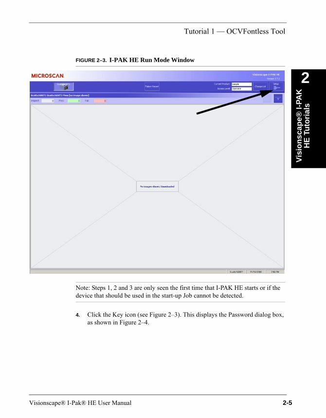
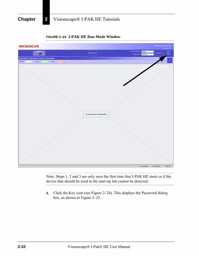
FIGURE 2–3. I-PAK HE Run Mode WindowNote: Steps 1, 2 and 3 are only seen the first time that I-PAK HE starts or if the device that should be used in the start-up Job cannot be detected.
4. Click the Key icon (see Figure 2–3). This displays the Password dialog box, as shown in Figure 2–4.
Visionscape® I-Pak® HE User Manual 2-5
Chapter 2 Visionscape® I-PAK HE Tutorials
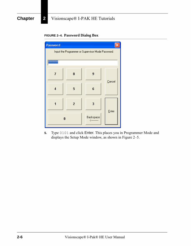
FIGURE 2–4. Password Dialog Box
5. Type 0101 and click Enter. This places you in Programmer Mode and displays the Setup Mode window, as shown in Figure 2–5.
2-6 Visionscape® I-Pak® HE User Manual

Tutorial 1 — OCVFontless Tool
Vis
ion
scap
e® I-
PAK
H
E T
uto
rial
s
2
FIGURE 2–5. I-PAK HE Setup Mode Window6. Click Advanced Settings.
7. Click Create a Product.
I-PAK HE displays the Select a Vision Device dialog box, as shown in Figure 2–6.
Visionscape® I-Pak® HE User Manual 2-7
Chapter 2 Visionscape® I-PAK HE Tutorials
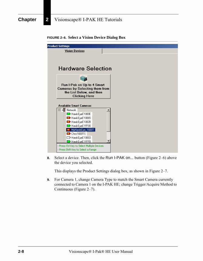
FIGURE 2–6. Select a Vision Device Dialog Box
8. Select a device. Then, click the Run I-PAK on... button (Figure 2–6) above the device you selected.
This displays the Product Settings dialog box, as shown in Figure 2–7.
9. For Camera 1, change Camera Type to match the Smart Camera currently connected to Camera 1 on the I-PAK HE; change Trigger/Acquire Method to Continuous (Figure 2–7).
2-8 Visionscape® I-Pak® HE User Manual

Tutorial 1 — OCVFontless Tool
Vis
ion
scap
e® I-
PAK
H
E T
uto
rial
s
2
FIGURE 2–7. Product Settings Dialog Box — Cameras Tab10. Click Next. This displays the Product Settings dialog box, Data Valid tab, as shown in Figure 2–8.
FIGURE 2–8. Product Settings Dialog Box — Data Valid Tab
11. Observe the default settings. Click Next. This displays the Product Setting dialog box — I/O tab, as shown in Figure 2–9.
Visionscape® I-Pak® HE User Manual 2-9

Chapter 2 Visionscape® I-PAK HE Tutorials
FIGURE 2–9. Product Settings — I/O Tab
12. Observe the default settings. Click Next. This displays the System Settings dialog box — Communication tab, as shown in Figure 2–10.
FIGURE 2–10. System Settings Dialog Box — Communication Tab
2-10 Visionscape® I-Pak® HE User Manual
Tutorial 1 — OCVFontless Tool
Vis
ion
scap
e® I-
PAK
H
E T
uto
rial
s
2
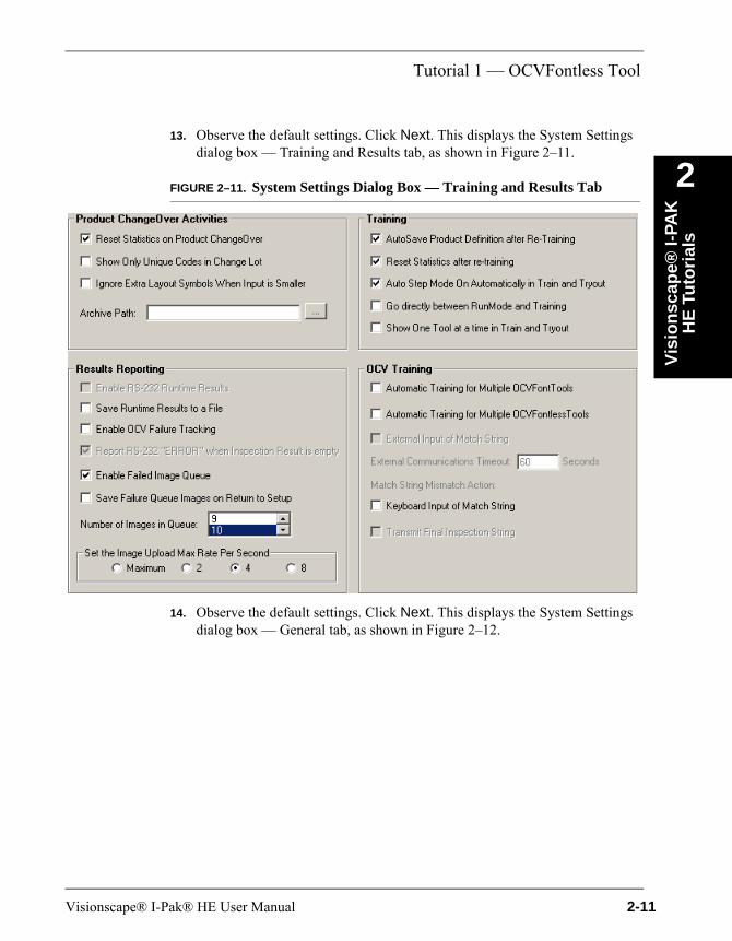
13. Observe the default settings. Click Next. This displays the System Settingsdialog box — Training and Results tab, as shown in Figure 2–11.
FIGURE 2–11. System Settings Dialog Box — Training and Results Tab
14. Observe the default settings. Click Next. This displays the System Settings dialog box — General tab, as shown in Figure 2–12.
Visionscape® I-Pak® HE User Manual 2-11
Chapter 2 Visionscape® I-PAK HE Tutorials
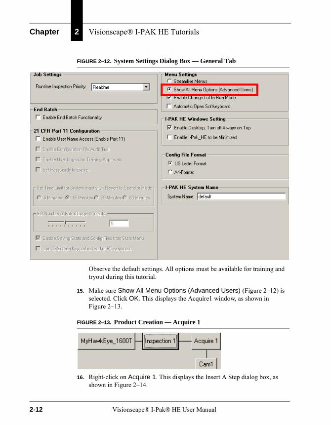
FIGURE 2–12. System Settings Dialog Box — General Tab
Observe the default settings. All options must be available for training and tryout during this tutorial.
15. Make sure Show All Menu Options (Advanced Users) (Figure 2–12) is selected. Click OK. This displays the Acquire1 window, as shown in Figure 2–13.
FIGURE 2–13. Product Creation — Acquire 1
16. Right-click on Acquire 1. This displays the Insert A Step dialog box, as shown in Figure 2–14.
2-12 Visionscape® I-Pak® HE User Manual

Tutorial 1 — OCVFontless Tool
Vis
ion
scap
e® I-
PAK
H
E T
uto
rial
s
2
FIGURE 2–14. Insert A Step Dialog Box17. Click (to select) OCVFontless Tool and click OK.
18. Right click on Acquire 1. Click (to select) Wait Step, and click OK. This displays the Product Creation dialog box shown in Figure 2–15.
FIGURE 2–15. Product Creation — OCVFontless Tool
Step 17
Step 18
Visionscape® I-Pak® HE User Manual 2-13
Chapter 2 Visionscape® I-PAK HE Tutorials
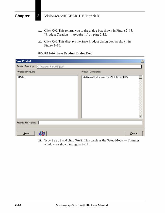
19. Click OK. This returns you to the dialog box shown in Figure 2–13, “Product Creation — Acquire 1,” on page 2-12.
20. Click OK. This displays the Save Product dialog box, as shown in Figure 2–16.
FIGURE 2–16. Save Product Dialog Box
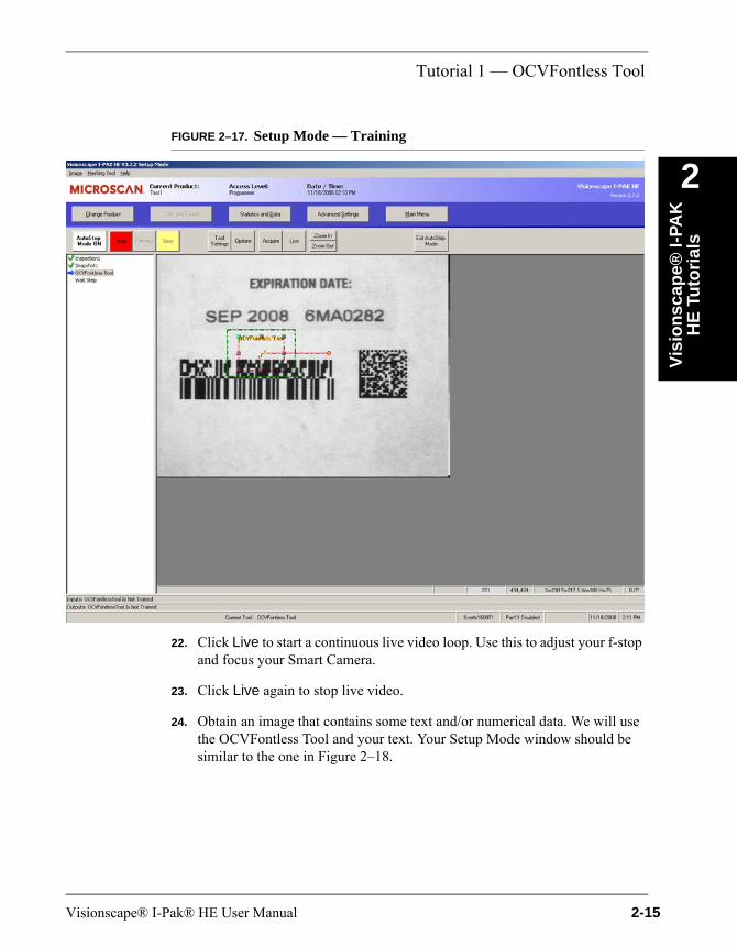
21. Type Test1 and click Save. This displays the Setup Mode — Training window, as shown in Figure 2–17.
2-14 Visionscape® I-Pak® HE User Manual
Tutorial 1 — OCVFontless Tool
Vis
ion
scap
e® I-
PAK
H
E T
uto
rial
s
2
FIGURE 2–17. Setup Mode — Training22. Click Live to start a continuous live video loop. Use this to adjust your f-stop and focus your Smart Camera.
23. Click Live again to stop live video.
24. Obtain an image that contains some text and/or numerical data. We will use the OCVFontless Tool and your text. Your Setup Mode window should be similar to the one in Figure 2–18.
Visionscape® I-Pak® HE User Manual 2-15

Chapter 2 Visionscape® I-PAK HE Tutorials
FIGURE 2–18. Setup Mode — OCVFontless Tool
25. The Train button shows red and the OCVFontless Tool is displayed. Drag the tool and place it around the appropriate text, as shown in Figure 2–19. Drag the AutoFind Tool and place it around the appropriate text, as shown in Figure 2–19.
2-16 Visionscape® I-Pak® HE User Manual

Tutorial 1 — OCVFontless Tool
Vis
ion
scap
e® I-
PAK
H
E T
uto
rial
s
2
FIGURE 2–19. Fontless FontTool Position26. Click Train. The Train button shows green. This indicates a successful train.
27. Click Next. The Next button text will change to Finish.
28. Click Finish. Click Options. This displays the Options dialog box, as shown in Figure 2–20.
Visionscape® I-Pak® HE User Manual 2-17
Chapter 2 Visionscape® I-PAK HE Tutorials
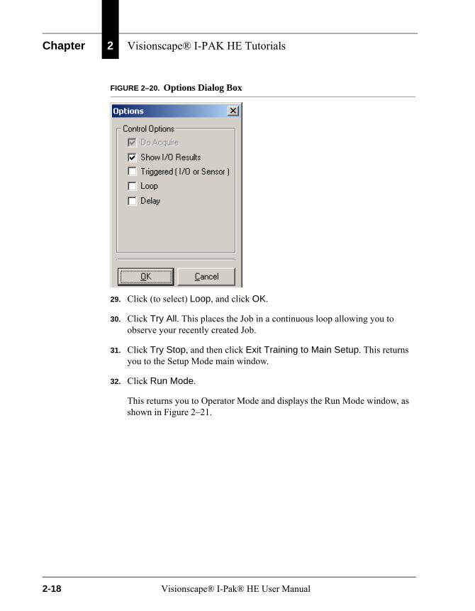
FIGURE 2–20. Options Dialog Box
29. Click (to select) Loop, and click OK.
30. Click Try All. This places the Job in a continuous loop allowing you to observe your recently created Job.
31. Click Try Stop, and then click Exit Training to Main Setup. This returns you to the Setup Mode main window.
32. Click Run Mode.
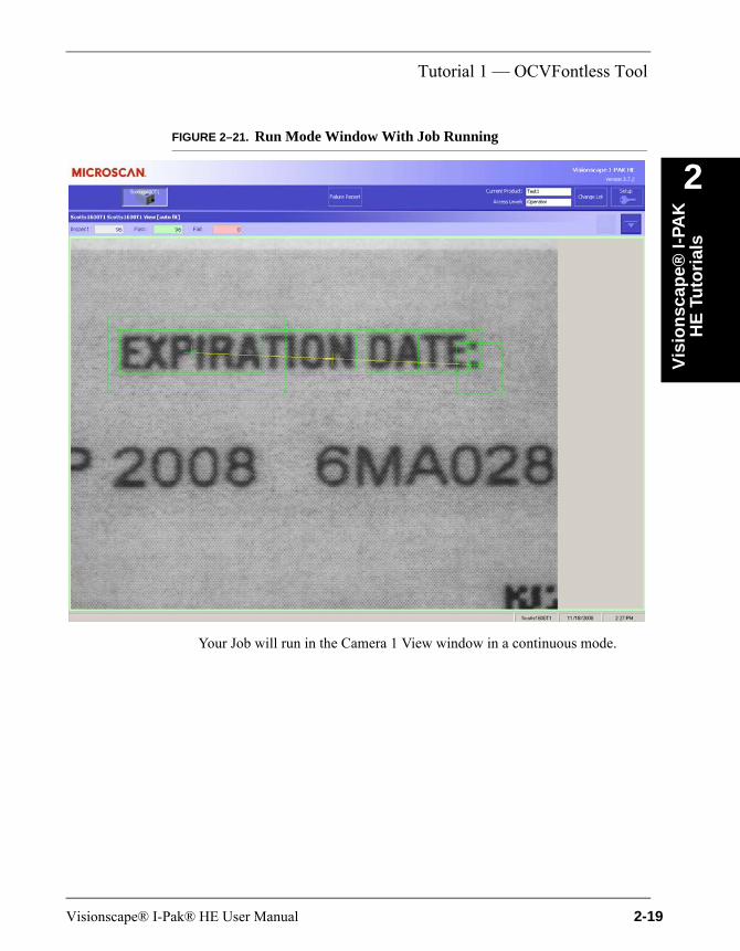
This returns you to Operator Mode and displays the Run Mode window, as shown in Figure 2–21.
2-18 Visionscape® I-Pak® HE User Manual
Tutorial 1 — OCVFontless Tool
Vis
ion
scap
e® I-
PAK
H
E T
uto
rial
s
2
FIGURE 2–21. Run Mode Window With Job RunningYour Job will run in the Camera 1 View window in a continuous mode.
Visionscape® I-Pak® HE User Manual 2-19
Chapter 2 Visionscape® I-PAK HE Tutorials
Tutorial 2 — OCVRuntimeToolThis tutorial takes you through the process of setting up an inspection using the OCVRuntimeTool. For more details, refer to “OCVRuntimeTool” on page 5-45.
Setting Up the Tool Set
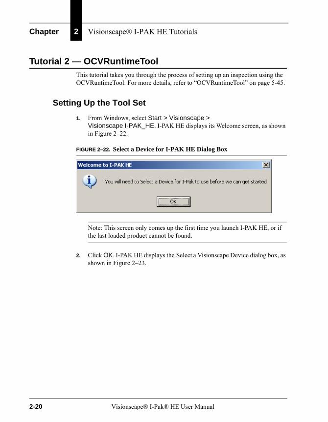
1. From Windows, select Start > Visionscape > Visionscape I-PAK_HE. I-PAK HE displays its Welcome screen, as shown in Figure 2–22.
FIGURE 2–22. Select a Device for I-PAK HE Dialog Box
Note: This screen only comes up the first time you launch I-PAK HE, or if the last loaded product cannot be found.
2. Click OK. I-PAK HE displays the Select a Visionscape Device dialog box, as shown in Figure 2–23.
2-20 Visionscape® I-Pak® HE User Manual

Tutorial 2 — OCVRuntimeTool
Vis
ion
scap
e® I-
PAK
H
E T
uto
rial
s
2
FIGURE 2–23. Select a Visionscape Device Dialog Box3. Select a device. Then, click the Select any Smart Camera... button.
Note: If the Smart Camera is connected directly to a PC (no network involved), I-PAK HE automatically chooses the Smart Camera, and you will not see the screen in Figure 2–23.
This starts I-PAK HE; the I-PAK HE Run Mode window is displayed, as shown in Figure 2–24.
Visionscape® I-Pak® HE User Manual 2-21
Chapter 2 Visionscape® I-PAK HE Tutorials
FIGURE 2–24. I-PAK HE Run Mode Window
Note: Steps 1, 2 and 3 are only seen the first time that I-PAK HE starts or if the device that should be used in the start-up Job cannot be detected.
4. Click the Key icon (see Figure 2–24). This displays the Password dialog box, as shown in Figure 2–25.
2-22 Visionscape® I-Pak® HE User Manual

Tutorial 2 — OCVRuntimeTool
Vis
ion
scap
e® I-
PAK
H
E T
uto
rial
s
2
FIGURE 2–25. Password Dialog Box5. Type 0101 and click Enter. This places you in Programmer Mode and displays the Setup Mode window, as shown in Figure 2–26.
Visionscape® I-Pak® HE User Manual 2-23

Chapter 2 Visionscape® I-PAK HE Tutorials
FIGURE 2–26. I-PAK HE Setup Mode Window
6. Click Advanced Settings.
7. Click Create a Product.
I-PAK HE displays the Select a Vision Device dialog box, as shown in Figure 2–27.
2-24 Visionscape® I-Pak® HE User Manual

Tutorial 2 — OCVRuntimeTool
Vis
ion
scap
e® I-
PAK
H
E T
uto
rial
s
2
FIGURE 2–27. Select a Vision Device Dialog Box8. Select a device. Then, click the button above the device you selected.
9. This displays the Product Settings dialog box, as shown in Figure 2–28.
10. For Camera 1, change Camera Type to match the Smart Camera currently connected to Camera 1 on the I-PAK HE; change Trigger/Acquire Method to Continuous, as shown in Figure 2–28.
Visionscape® I-Pak® HE User Manual 2-25

Chapter 2 Visionscape® I-PAK HE Tutorials
FIGURE 2–28. Product Settings Dialog Box — Cameras Tab
11. Click Next. This displays the Product Settings dialog box, Data Valid tab, as shown in Figure 2–29.
FIGURE 2–29. Product Settings Dialog Box — Data Valid Tab
12. Observe the default settings. Click Next. This displays the Product Setting dialog box — I/O tab, as shown in Figure 2–30.
2-26 Visionscape® I-Pak® HE User Manual
Tutorial 2 — OCVRuntimeTool
Vis
ion
scap
e® I-
PAK
H
E T
uto
rial
s
2
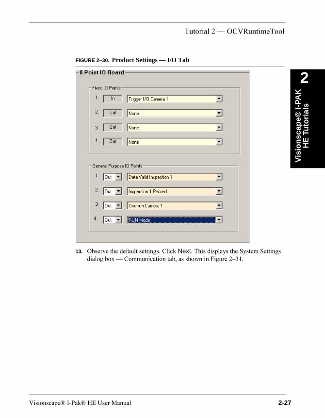
FIGURE 2–30. Product Settings — I/O Tab13. Observe the default settings. Click Next. This displays the System Settings dialog box — Communication tab, as shown in Figure 2–31.
Visionscape® I-Pak® HE User Manual 2-27
Chapter 2 Visionscape® I-PAK HE Tutorials
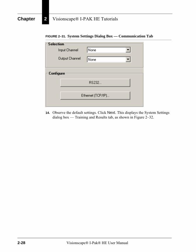
FIGURE 2–31. System Settings Dialog Box — Communication Tab
14. Observe the default settings. Click Next. This displays the System Settings dialog box — Training and Results tab, as shown in Figure 2–32.
2-28 Visionscape® I-Pak® HE User Manual

Tutorial 2 — OCVRuntimeTool
Vis
ion
scap
e® I-
PAK
H
E T
uto
rial
s
2
FIGURE 2–32. System Settings Dialog Box — Training and Results Tab15. Observe the default settings. Click Next. This displays the System Settings dialog box — General tab, as shown in Figure 2–33.
Visionscape® I-Pak® HE User Manual 2-29

Chapter 2 Visionscape® I-PAK HE Tutorials
FIGURE 2–33. System Settings Dialog Box — General Tab
Observe the default settings. All options must be available for training and tryout during this tutorial.
16. Make sure Show All Menu Options (Advanced Users) (Figure 2–33) is selected. Click OK. This displays the Acquire1 window, as shown in Figure 2–34.
FIGURE 2–34. Product Creation — Acquire 1
17. Right-click on Acquire 1. This displays the Insert A Step dialog box, as shown in Figure 2–35.
2-30 Visionscape® I-Pak® HE User Manual
Tutorial 2 — OCVRuntimeTool
Vis
ion
scap
e® I-
PAK
H
E T
uto
rial
s
2
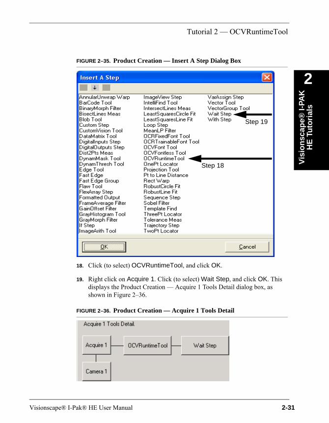
FIGURE 2–35. Product Creation — Insert A Step Dialog Box18. Click (to select) OCVRuntimeTool, and click OK.
19. Right click on Acquire 1. Click (to select) Wait Step, and click OK. This displays the Product Creation — Acquire 1 Tools Detail dialog box, as shown in Figure 2–36.
FIGURE 2–36. Product Creation — Acquire 1 Tools Detail
Step 18
Step 19
Visionscape® I-Pak® HE User Manual 2-31
Chapter 2 Visionscape® I-PAK HE Tutorials
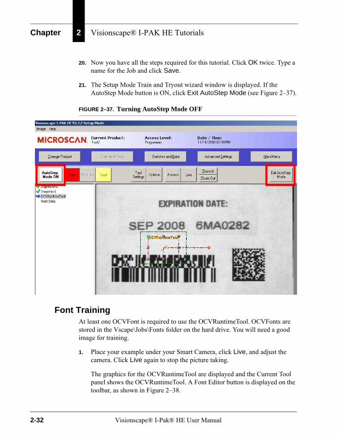
20. Now you have all the steps required for this tutorial. Click OK twice. Type a name for the Job and click Save.
21. The Setup Mode Train and Tryout wizard window is displayed. If the AutoStep Mode button is ON, click Exit AutoStep Mode (see Figure 2–37).
FIGURE 2–37. Turning AutoStep Mode OFF
Font TrainingAt least one OCVFont is required to use the OCVRuntimeTool. OCVFonts are stored in the Vscape\Jobs\Fonts folder on the hard drive. You will need a good image for training.
1. Place your example under your Smart Camera, click Live, and adjust the camera. Click Live again to stop the picture taking.
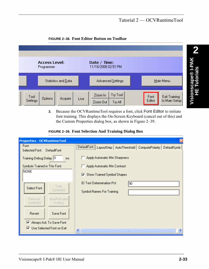
The graphics for the OCVRuntimeTool are displayed and the Current Tool panel shows the OCVRuntimeTool. A Font Editor button is displayed on the toolbar, as shown in Figure 2–38.
2-32 Visionscape® I-Pak® HE User Manual
Tutorial 2 — OCVRuntimeTool
Vis
ion
scap
e® I-
PAK
H
E T
uto
rial
s
2
FIGURE 2–38. Font Editor Button on Toolbar2. Because the OCVRuntimeTool requires a font, click Font Editor to initiate font training. This displays the On-Screen Keyboard (cancel out of this) and the Custom Properties dialog box, as shown in Figure 2–39.
FIGURE 2–39. Font Selection And Training Dialog Box
Visionscape® I-Pak® HE User Manual 2-33
Chapter 2 Visionscape® I-PAK HE Tutorials
The Custom Properties dialog box allows you to train of OCVFonts in the current image. The Select Font button allows you to select an OCVFont to train.
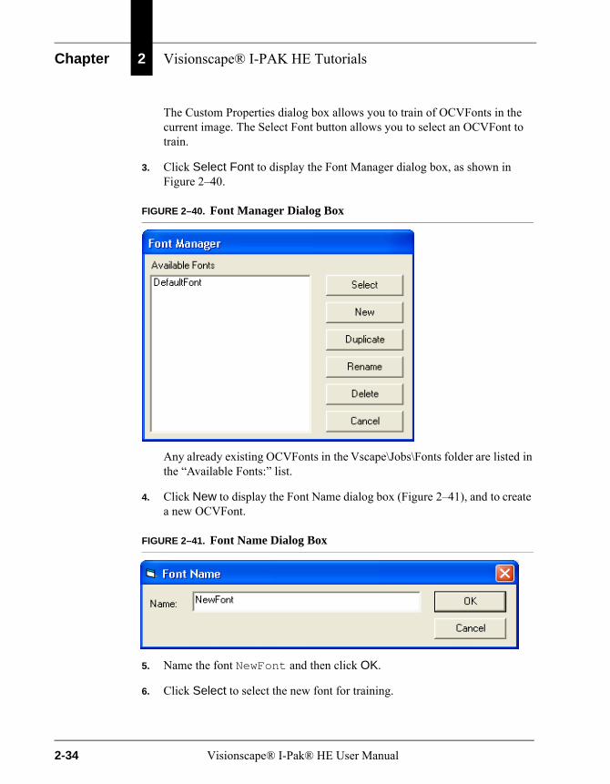
3. Click Select Font to display the Font Manager dialog box, as shown in Figure 2–40.
FIGURE 2–40. Font Manager Dialog Box
Any already existing OCVFonts in the Vscape\Jobs\Fonts folder are listed in the “Available Fonts:” list.
4. Click New to display the Font Name dialog box (Figure 2–41), and to create a new OCVFont.
FIGURE 2–41. Font Name Dialog Box
5. Name the font NewFont and then click OK.
6. Click Select to select the new font for training.
2-34 Visionscape® I-Pak® HE User Manual
Tutorial 2 — OCVRuntimeTool
Vis
ion
scap
e® I-
PAK
H
E T
uto
rial
s
2
By default, I-PAK HE OCVFont training does not perform automatic segmentation so that it can better perform Runtime ID Checking. For this tutorial, we will turn automatic segmentation on, so that I-PAK HE automatically locates and places a box around all characters in the FOV. This makes the tutorial easier.The tool settings for the selected font are on the right hand side of the Custom Properties dialog box.
7. Click the Layout Step tab in the right pane.
8. Click (to select) Automatic Segmentation.
9. Move the Custom Properties dialog box so that you can see the image and the training box.
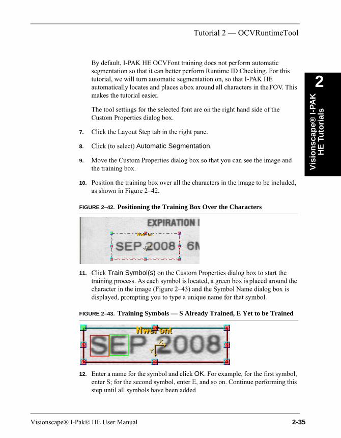
10. Position the training box over all the characters in the image to be included, as shown in Figure 2–42.
FIGURE 2–42. Positioning the Training Box Over the Characters
11. Click Train Symbol(s) on the Custom Properties dialog box to start the training process. As each symbol is located, a green box is placed around the character in the image (Figure 2–43) and the Symbol Name dialog box is displayed, prompting you to type a unique name for that symbol.
FIGURE 2–43. Training Symbols — S Already Trained, E Yet to be Trained
12. Enter a name for the symbol and click OK. For example, for the first symbol, enter S; for the second symbol, enter E, and so on. Continue performing this step until all symbols have been added
Visionscape® I-Pak® HE User Manual 2-35
Chapter 2 Visionscape® I-PAK HE Tutorials
Each symbol is stored as part of the OCVFont. After you click OK, the current box turns red and a green box is placed around the next character in the image.
Click Skip to pass over a character that is a duplicate. You can Cancel training at anytime, in which case, no more symbols are added to the OCVFont.
13. After all symbols are trained, click Save Font to save the OCVFont.
14. Close the Custom Properties dialog box.
Now, you are ready to continue with the Setup Mode Train and Tryout wizard window.
OCVRuntimeTool Training
1. In the left pane, select the OCVRuntimeTool.
Now that the OCVFont has been trained, it needs to be selected for use by the OCVRuntimeTool.
2. Click Tool Settings. Click the Layout Step tab. Select the font named “NewFont” from the “Selected Font” list, and click Close.
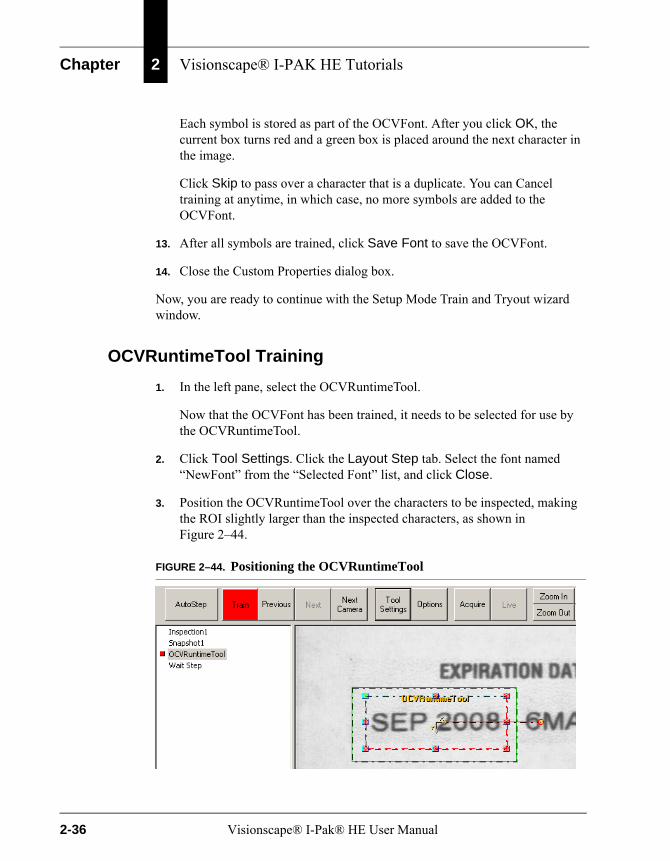
3. Position the OCVRuntimeTool over the characters to be inspected, making the ROI slightly larger than the inspected characters, as shown in Figure 2–44.
FIGURE 2–44. Positioning the OCVRuntimeTool
2-36 Visionscape® I-Pak® HE User Manual
Tutorial 2 — OCVRuntimeTool
Vis
ion
scap
e® I-
PAK
H
E T
uto
rial
s
2
4. To start the training process, click Train.As symbols in the OCVFont are found in the image, boxes are placed over those positions. When all candidate layout positions are found, any conflicts (two or more symbols found in the same position) are resolved using runtime ID checking information. Each position of the final layout is then trained as a symbol in a new font, the Runtime font.
The Approve Inspect Characters window is displayed at the end of the Train (learn layout) with the string of Inspect Chars:, as shown in Figure 2–45.
Visionscape® I-Pak® HE User Manual 2-37

Chapter 2 Visionscape® I-PAK HE Tutorials
FIGURE 2–45. Setup Mode — Approve Inspect Characters
This allows characters to be substituted into the layout or ignored entirely.
2-38 Visionscape® I-Pak® HE User Manual

Tutorial 2 — OCVRuntimeTool
Vis
ion
scap
e® I-
PAK
H
E T
uto
rial
s
2
5. Click Substitute to display the Layout and Font boxes shown inFigure 2–46.
FIGURE 2–46. Setup Mode — Layout and Font Boxes
The list of symbol names displayed in the Layout box contains the names of all symbols in the layout, in the order in which they appear. The Font box contains the name of all symbols in the selected OCVFont. The first item in the list is IGN, which is used to ignore characters.
6. To substitute one symbol for another, select the character in the Layout box that you want to substitute for. Select the symbol from the Font box that you want to use to replace the layout symbol. Click Substitute. The Layout box and Inspect Chars: are updated.
7. To ignore one of the symbols in the layout (exclude it from being inspected at runtime), select the symbol to be ignored from the Layout box. Select IGN
Visionscape® I-Pak® HE User Manual 2-39
Chapter 2 Visionscape® I-PAK HE Tutorials
from the Font box. Click Substitute. The symbol is removed from the Layout box and Inspect Chars:.
If you wish to retrain the tool, with the OCVRuntimeTool selected, click Train Tool in the Setup Mode Train window. You can adjust the properties of the tool and retrain until you achieve the desired layout string.
8. Once you are satisfied with the layout shown in the Inspect Chars: string, click Approve to return to the Setup Mode Train and Tryout wizard window.
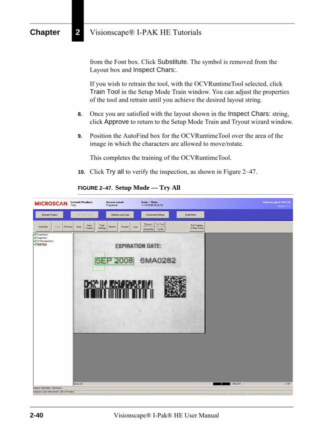
9. Position the AutoFind box for the OCVRuntimeTool over the area of the image in which the characters are allowed to move/rotate.
This completes the training of the OCVRuntimeTool.
10. Click Try all to verify the inspection, as shown in Figure 2–47.
FIGURE 2–47. Setup Mode — Try All
2-40 Visionscape® I-Pak® HE User Manual
Tutorial 2 — OCVRuntimeTool
Vis
ion
scap
e® I-
PAK
H
E T
uto
rial
s
2
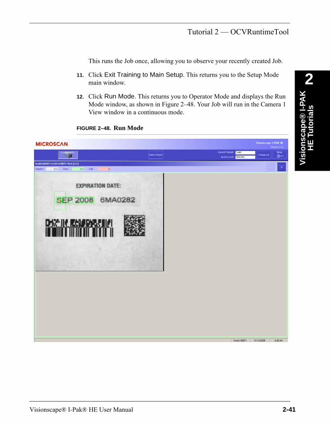
This runs the Job once, allowing you to observe your recently created Job.11. Click Exit Training to Main Setup. This returns you to the Setup Mode main window.
12. Click Run Mode. This returns you to Operator Mode and displays the Run Mode window, as shown in Figure 2–48. Your Job will run in the Camera 1 View window in a continuous mode.
FIGURE 2–48. Run Mode
Visionscape® I-Pak® HE User Manual 2-41
Chapter 2 Visionscape® I-PAK HE Tutorials
What’s NextCongratulations! You have successfully created, set up, and stored an I-PAK HE program, trained the tools, and executed both a tryout and continuous inspection in runtime.
This tutorial highlights the basic functionality of I-PAK HE and provides a foundation for properly operating the product. You are ready to go into full operation using I-PAK HE.
2-42 Visionscape® I-Pak® HE User Manual
3
21 C
FR
Par
t 11
3
CHAPTER 3 21 CFR Part 11Visionscape® I-PAK® HE is 21 CFR Part 11 technically compliant. This chapter describes the following:
• “Components” on page 3-1
• “Access Levels” on page 3-2
• “Enabling 21 CFR Part 11” on page 3-3
• “The I-PAK Administrator” on page 3-4
• “Customer Responsibilities” on page 3-5
• “21 CFR Part 11 Functions” on page 3-7
• “Common 21 CFR Part 11 Areas of Concern” on page 3-19
ComponentsI-PAK HE’s technical 21 CFR Part 11 compliancy has the following components:
• I-PAK HE Jobs are stored on the PC as binary files; you cannot edit them except from within I-PAK HE. These “Jobs” are the vision applications, “recipes” or step-by-step instructions that the vision system follows to inspect product. Typically, you would associate one Job per product being inspected and change or retrain the Date/Lot Code or Expiration date while leaving everything else the same.
Visionscape® I-Pak® HE User Manual 3-1
Chapter 3 21 CFR Part 11
• I-PAK HE’s Audit Trail is a centralized, chronological, time-stamped journal file of all I-PAK HE activities: from the automatic start-up of I-PAK HE as part of the PC Start-Up items noting the version of I-PAK HE software, through user login attempts, to every button pushed, every retraining action, every new layout string and Data Matrix match strings, every alarm acknowledged and the Statistics entering and exiting Run Mode (Inspection). The Audit File records who makes a change and the reason for the change. It is available for printout using Adobe Acrobat’s PDF format - another safeguard to prevent unauthorized modification of the Audit Trail - from inside I-PAK HE as part of the I-PAK Administrator’s role (see “The I-PAK Administrator” on page 3-4).
• I-PAK HE’s Configuration Files are an ASCII representation of the data contained on I-PAK HE “Job” files. These are provided for the convenience of our I-PAK HE customers to provide a readable representation of the logic being used in the inspection. They are stored on the PC as read-only files and are viewable from within I-PAK HE as part of the I-PAK Administrator’s role. Additionally, the I-PAK Administrator can reconcile between two of these files to note detailed changes of all Job settings.
• I-PAK HE’s Statistics Files are an ASCII representation of the last inspection results. These are summaries, and contain the Inspection total, pass and failed as well as the inspection string (when applicable) and the last login name and the timestamp of the last run of the inspection. These are provided for the convenience of our I-PAK HE customers to provide a readable representation of the data results from the inspection. They are stored on the PC as read-only files and are viewable, printable and exportable from I-PAK HE as part of the Statistics/Data SubMenu. The data contained within these files is recorded automatically in the Audit Trail.
Access LevelsThe I-PAK HE access levels (Setup Mode) are shown in Figure 3–1.
3-2 Visionscape® I-Pak® HE User Manual
Enabling 21 CFR Part 11
21 C
FR
Par
t 11
3
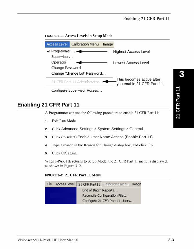
FIGURE 3–1. Access Levels in Setup Mode
Enabling 21 CFR Part 11A Programmer can use the following procedure to enable 21 CFR Part 11:
1. Exit Run Mode.
2. Click Advanced Settings > System Settings > General.
3. Click (to select) Enable User Name Access (Enable Part 11).
4. Type a reason in the Reason for Change dialog box, and click OK.
5. Click OK again.
When I-PAK HE returns to Setup Mode, the 21 CFR Part 11 menu is displayed, as shown in Figure 3–2.
FIGURE 3–2. 21 CFR Part 11 Menu
Highest Access Level
Lowest Access Level
This becomes active afteryou enable 21 CFR Part 11
Visionscape® I-Pak® HE User Manual 3-3
Chapter 3 21 CFR Part 11
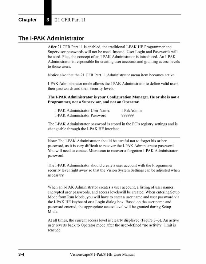
The I-PAK AdministratorAfter 21 CFR Part 11 is enabled, the traditional I-PAK HE Programmer and Supervisor passwords will not be used. Instead, User Login and Passwords will be used. Plus, the concept of an I-PAK Administrator is introduced. An I-PAK Administrator is responsible for creating user accounts and granting access levels to those users.
Notice also that the 21 CFR Part 11 Administrator menu item becomes active.
I-PAK Administrator mode allows the I-PAK Administrator to define valid users, their passwords and their security levels.
The I-PAK Administrator is your Configuration Manager. He or she is not a Programmer, not a Supervisor, and not an Operator.
I-PAK Administrator User Name: I-PakAdminI-PAK Administrator Password: 999999
The I-PAK Administrator password is stored in the PC’s registry settings and is changeable through the I-PAK HE interface.
Note: The I-PAK Administrator should be careful not to forget his or her password, as it is very difficult to recover the I-PAK Administrator password. You will need to contact Microscan to recover a forgotten I-PAK Administrator password.
The I-PAK Administrator should create a user account with the Programmer security level right away so that the Vision System Settings can be adjusted when necessary.
When an I-PAK Administrator creates a user account, a listing of user names, encrypted user passwords, and access levels will be created. When entering Setup Mode from Run Mode, you will have to enter a user name and user password via the I-PAK HE keyboard or a Login dialog box. Based on the user name and password entered, the appropriate access level will be granted during Setup Mode.
At all times, the current access level is clearly displayed (Figure 3–3). An active user reverts back to Operator mode after the user-defined “no activity” limit is reached.
3-4 Visionscape® I-Pak® HE User Manual
Customer Responsibilities
21 C
FR
Par
t 11
3
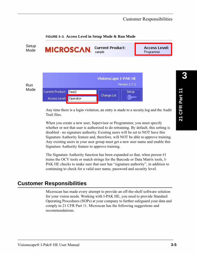
FIGURE 3–3. Access Level in Setup Mode & Run Mode
Any time there is a login violation, an entry is made to a secuity.log and the Audit Trail files.
When you create a new user, Supervisor or Programmer, you must specify whether or not that user is authorized to do retraining. By default, this setting is disabled - no signature authority. Existing users will be set to NOT have this Signature Authority feature and, therefore, will NOT be able to approve training. Any existing users in your user group must get a new user name and enable this Signature Authority feature to approve training.
The Signature Authority function has been expanded so that, when person #1 trains the OCV tools or match strings for the Barcode or Data Matrix tools, I-PAK HE checks to make sure that user has “signature authority”, in addition to continuing to check for a valid user name, password and security level.
Customer ResponsibilitiesMicroscan has made every attempt to provide an off-the-shelf software solution for your vision needs. Working with I-PAK HE, you need to provide Standard Operating Procedures (SOPs) at your company to further safeguard your data and comply to 21 CFR Part 11. Microscan has the following suggestions and recommendations.
SetupMode
RunMode
Visionscape® I-Pak® HE User Manual 3-5
Chapter 3 21 CFR Part 11
Starting I-PAK HE, Using Part 11 & Adding I-PAK HE Users
1. Determine who in your company will be the I-PAK Administrator. Remember, the I-PAK Administrator creates user accounts but does not have any “programming” rights - the I-PAK Administrator is neither an I-PAK HE Operator, Supervisor, nor Programmer.
2. Determine who will be a Programmer. Microscan recommends this be a factory-trained I-PAK HE user. The Programmer will set up the vision Jobs and adjust settings.
3. Determine who will be your Supervisors, those who can retrain the vision tools to perhaps train a new lot code and those who can perform a Product ChangeOver to start inspection on another product type. Another decision in your Supervisor Configuration is what access they have to the I-PAK HE System and whether or not they have the ability to retrain key tools such as a Font Tool. The Programmer can set up the Supervisors Access rights by selecting Access Level > Configure Supervisor Access. The I-PAK Administrator assigns the right to retrain when they create a user account. For more information, see Configure Supervisor Access on page 6–5.
Note: Create an SOP that defines your users and their access rights.
4. Turn on Part 11 in I-PAK HE (see “Enabling 21 CFR Part 11” on page 3-3). By default, to provide a generic solution for all our customers, Part 11 is not enabled. This setting turns on Part 11 and the Audit Trail.
Note: Create an SOP to never turn this option off.
• Enable any other Advanced Settings > System Settings > General > 21 CFR Part 11 Configuration menu items that you require. These are dependent on your regulations. For example, if you require that passwords expire, set the Advanced Settings > System Settings > General > Set Passwords To Expire option, as well as specifying the duration of the password. For more information about the menu items, see “21 CFR Part 11 Configuration” on page 6-91.
Note: Create an SOP that defines your password expiration duration.
3-6 Visionscape® I-Pak® HE User Manual

21 CFR Part 11 Functions
21 C
FR
Par
t 11
3
5. Now, bring in your I-PAK Administrator to begin assigning login names, passwords, access and retraining rights. Always remember to define a Programmer and at least one Supervisor. Your day-to-day users should be Operators and Supervisors.
When an I-PAK Administrator creates a user account, a listing of user names, encrypted user passwords and access levels will be created. When entering Setup Mode from Run Mode, you will have to enter a user name and user password via the I-PAK HE keyboard or a Login dialog box. Based on the user name and password entered, the appropriate access level will be granted during Setup Mode.
Note: A 21 CFR Part 11 System Setting (Use OnScreen Keypad instead of PC Keyboard) enables an OnScreen Keyboard for entering login and training approval user names and passwords rather than the I-PAK HE keyboard. For more information, see page 6–94.
At all times, the current access level is clearly displayed. An active user reverts back to Operator mode after the user-defined “no activity” limit is reached.
Any time there is a violation, an entry is made to a security.log file. An I-PAK Administrator can view this file from I-PAK HE by clicking on Configure 21 CFR Part 11 Users > Display Login Violation Log.
21 CFR Part 11 FunctionsThe 21 CFR Part 11 drop-down menu is accessible for I-PAK Administrator, Programmers, and Supervisors. Operators have no access or visibility into this area of the software.
Typically, at the end of a batch or a run of product, you’ll want to gather your data and record your inspection counts for Part 11 records. These records and this functionality is discussed below.
End of Batch ReportsAfter you have finished running successfully a batch of product, you may need to store the pertinent information about that batch to a secure place for future review and reconciliation. An I-PAK HE Supervisor, Programmer, or the I-PAK Administrator can view the batch reports, create PDF records of the batch data, print these PDFs, and archive these PDFs to your archive device.
Visionscape® I-Pak® HE User Manual 3-7

Chapter 3 21 CFR Part 11
Note: Any time you write a file to disk or CD, such as when you create a PDF or write that PDF to disk, I-PAK HE checks to make sure there is room on the device for the files. It will post an error if there is not enough room to write the file.
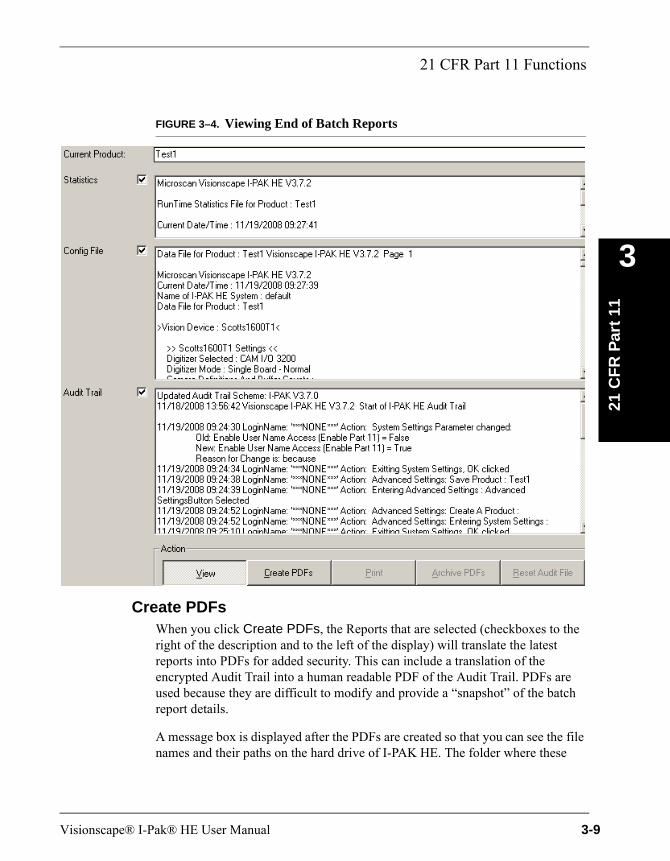
When you click 21 CFR Part11 > End of Batch Reports…, you will see a dialog box that contains the latest Inspection Results and its support files, as shown in Figure 3–4. By default, you are presented with its “View” option. This shows you the information from the Statistics File, the Configuration File and the decrypted Audit Trail. You can choose to select all or some of these files for the other options.
3-8 Visionscape® I-Pak® HE User Manual
21 CFR Part 11 Functions
21 C
FR
Par
t 11
3
FIGURE 3–4. Viewing End of Batch Reports
Create PDFsWhen you click Create PDFs, the Reports that are selected (checkboxes to the right of the description and to the left of the display) will translate the latest reports into PDFs for added security. This can include a translation of the encrypted Audit Trail into a human readable PDF of the Audit Trail. PDFs are used because they are difficult to modify and provide a “snapshot” of the batch report details.
A message box is displayed after the PDFs are created so that you can see the file names and their paths on the hard drive of I-PAK HE. The folder where these
Visionscape® I-Pak® HE User Manual 3-9
Chapter 3 21 CFR Part 11
PDFs live is in a subfolder where I-PAK HE is installed and in their own “PDF” folder. Typically, this is a path like: C:\Vscape\I-Pak_HE\Jobs\PDFs.
Each PDF uses a file name that contains the date/time stamp of when you created these PDF reports and the type of report it is. For example, the Statistics PDF might be called something like:
C:\Vscape\I-Pak_HE\Jobs\PDFs\IpakStats-11-19-2008-10:02_50.pdf
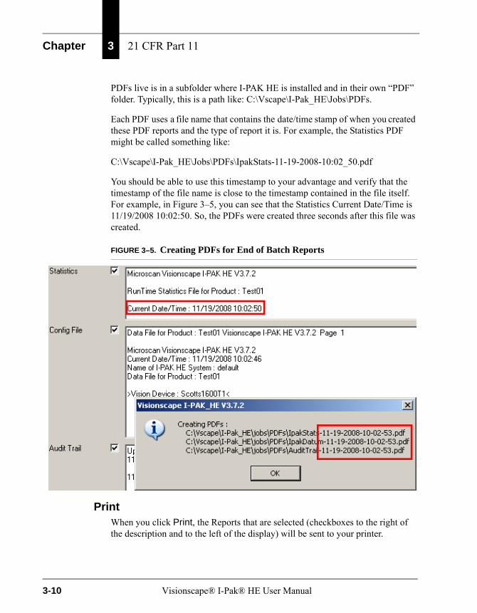
You should be able to use this timestamp to your advantage and verify that the timestamp of the file name is close to the timestamp contained in the file itself. For example, in Figure 3–5, you can see that the Statistics Current Date/Time is 11/19/2008 10:02:50. So, the PDFs were created three seconds after this file was created.
FIGURE 3–5. Creating PDFs for End of Batch Reports
PrintWhen you click Print, the Reports that are selected (checkboxes to the right of the description and to the left of the display) will be sent to your printer.
3-10 Visionscape® I-Pak® HE User Manual

21 CFR Part 11 Functions
21 C
FR
Par
t 11
3
Note: Make sure you have set up previously a network or local printer. I-PAK HE will look for the printer defined on the system.
Archive PDFsWhen you click Archive PDFs, the Reports that are selected (checkboxes to the right of the description and to the left of the display) and that have PDFs created, will be archived to your archive device. Also, you can archive to every path selected in System Settings independent from the device type. This can also be a USB Stick or any device that is connected to the PC and ready to store data.
Microscan strongly suggests you use the internal CD R/W device as your archive device and set the path to D: (or whatever is your local CD R/W drive path).
Note: You need to set up the archive path via the System Settings Menu.
You need to put a blank CD into the CD R/W drive and format it using Direct CD; format it to allow multiple file writes from a program such as Windows Explorer. Format the media before trying to use this feature.
When creating these archives on CD, several things are happening for top security. First, a folder is created on the CD using the current time/date stamp concatenated with the current product's name. The PDFs are written to the CD using the previous names with the time/date stamp. This ensures that the files are not modified, as the file date/times themselves MUST be consistent with the file and folder names. A few seconds differences in these is all that can be expected to be different.
Note: You should create an SOP to verify these date/times on the folder and file names and inside the files themselves to ensure no one is corrupting your data.
A message box (Figure 3–6) is displayed after the PDFs are written so that you can see the file names and their paths on the archive device of I-PAK HE.
Visionscape® I-Pak® HE User Manual 3-11
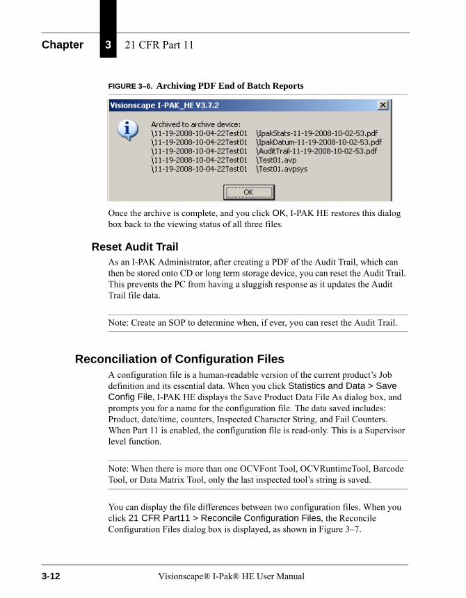
Chapter 3 21 CFR Part 11
FIGURE 3–6. Archiving PDF End of Batch Reports
Once the archive is complete, and you click OK, I-PAK HE restores this dialog box back to the viewing status of all three files.
Reset Audit TrailAs an I-PAK Administrator, after creating a PDF of the Audit Trail, which can then be stored onto CD or long term storage device, you can reset the Audit Trail. This prevents the PC from having a sluggish response as it updates the Audit Trail file data.
Note: Create an SOP to determine when, if ever, you can reset the Audit Trail.
Reconciliation of Configuration FilesA configuration file is a human-readable version of the current product’s Job definition and its essential data. When you click Statistics and Data > Save Config File, I-PAK HE displays the Save Product Data File As dialog box, and prompts you for a name for the configuration file. The data saved includes: Product, date/time, counters, Inspected Character String, and Fail Counters. When Part 11 is enabled, the configuration file is read-only. This is a Supervisor level function.
Note: When there is more than one OCVFont Tool, OCVRuntimeTool, Barcode Tool, or Data Matrix Tool, only the last inspected tool’s string is saved.
You can display the file differences between two configuration files. When you click 21 CFR Part11 > Reconcile Configuration Files, the Reconcile Configuration Files dialog box is displayed, as shown in Figure 3–7.
3-12 Visionscape® I-Pak® HE User Manual

21 CFR Part 11 Functions
21 C
FR
Par
t 11
3
FIGURE 3–7. Reconcile Configuration Files
The upper left of the display shows you all the files in your I-Pak_HE\Jobs\ConfigurationArchive folder. From here, you select the two files you wish to reconcile (perform a file difference on). When you click Reconcile, the lower display region will show you the file differences.
You can view these differences or save them to a file by clicking File > Save As. You can also print these file difference by clicking File > Print.
Configure 21 CFR Part 11 UsersWhen you click on this, I-PAK HE displays the Configure I-PAK Users dialog box. If you’re the I-PAK Administrator, you can use the commands shown in Figure 3–8.
Visionscape® I-Pak® HE User Manual 3-13
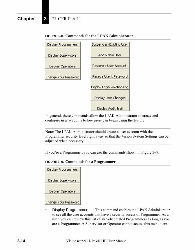
Chapter 3 21 CFR Part 11
FIGURE 3–8. Commands for the I-PAK Administrator
In general, these commands allow the I-PAK Administrator to create and configure user accounts before users can begin using the feature.
Note: The I-PAK Administrator should create a user account with the Programmer security level right away so that the Vision System Settings can be adjusted when necessary.
If you’re a Programmer, you can use the commands shown in Figure 3–9.
FIGURE 3–9. Commands for a Programmer
• Display Programmers — This command enables the I-PAK Administrator to see all the user accounts that have a security access of Programmer. As a user, you can review this list of already created Programmers as long as you are a Programmer. A Supervisor or Operator cannot access this menu item.
3-14 Visionscape® I-Pak® HE User Manual
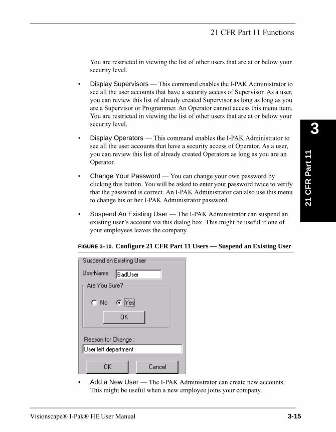
21 CFR Part 11 Functions
21 C
FR
Par
t 11
3
You are restricted in viewing the list of other users that are at or below your security level.
• Display Supervisors — This command enables the I-PAK Administrator to see all the user accounts that have a security access of Supervisor. As a user, you can review this list of already created Supervisor as long as long as you are a Supervisor or Programmer. An Operator cannot access this menu item. You are restricted in viewing the list of other users that are at or below your security level.
• Display Operators — This command enables the I-PAK Administrator to see all the user accounts that have a security access of Operator. As a user, you can review this list of already created Operators as long as you are an Operator.
• Change Your Password — You can change your own password by clicking this button. You will be asked to enter your password twice to verify that the password is correct. An I-PAK Administrator can also use this menu to change his or her I-PAK Administrator password.
• Suspend An Existing User — The I-PAK Administrator can suspend an existing user’s account via this dialog box. This might be useful if one of your employees leaves the company.
FIGURE 3–10. Configure 21 CFR Part 11 Users — Suspend an Existing User
• Add a New User — The I-PAK Administrator can create new accounts. This might be useful when a new employee joins your company.
Visionscape® I-Pak® HE User Manual 3-15
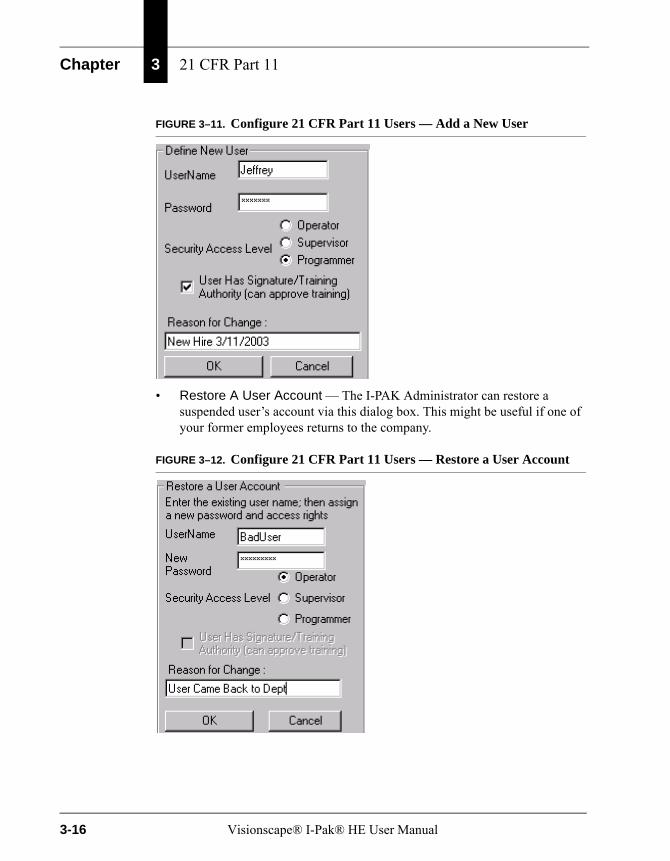
Chapter 3 21 CFR Part 11
FIGURE 3–11. Configure 21 CFR Part 11 Users — Add a New User
• Restore A User Account — The I-PAK Administrator can restore a suspended user’s account via this dialog box. This might be useful if one of your former employees returns to the company.
FIGURE 3–12. Configure 21 CFR Part 11 Users — Restore a User Account
3-16 Visionscape® I-Pak® HE User Manual
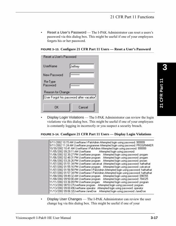
21 CFR Part 11 Functions
21 C
FR
Par
t 11
3
• Reset a User’s Password — The I-PAK Administrator can reset a users’s password via this dialog box. This might be useful if one of your employees forgets his or her password.
FIGURE 3–13. Configure 21 CFR Part 11 Users — Reset a User’s Password
• Display Login Violations — The I-PAK Administrator can review the login violations via this dialog box. This might be useful if one of your employees is constantly logging in incorrectly or you suspect a security breach.
FIGURE 3–14. Configure 21 CFR Part 11 Users — Display Login Violations
• Display User Changes — The I-PAK Administrator can review the user change log via this dialog box. This might be useful if one of your
Visionscape® I-Pak® HE User Manual 3-17
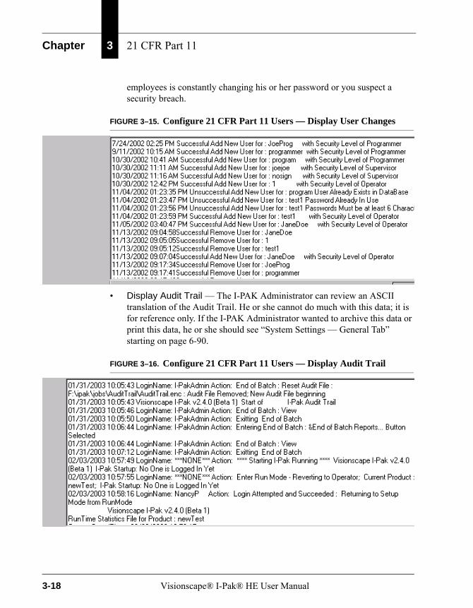
Chapter 3 21 CFR Part 11
employees is constantly changing his or her password or you suspect a security breach.
FIGURE 3–15. Configure 21 CFR Part 11 Users — Display User Changes
• Display Audit Trail — The I-PAK Administrator can review an ASCII translation of the Audit Trail. He or she cannot do much with this data; it is for reference only. If the I-PAK Administrator wanted to archive this data or print this data, he or she should see “System Settings — General Tab” starting on page 6-90.
FIGURE 3–16. Configure 21 CFR Part 11 Users — Display Audit Trail
3-18 Visionscape® I-Pak® HE User Manual
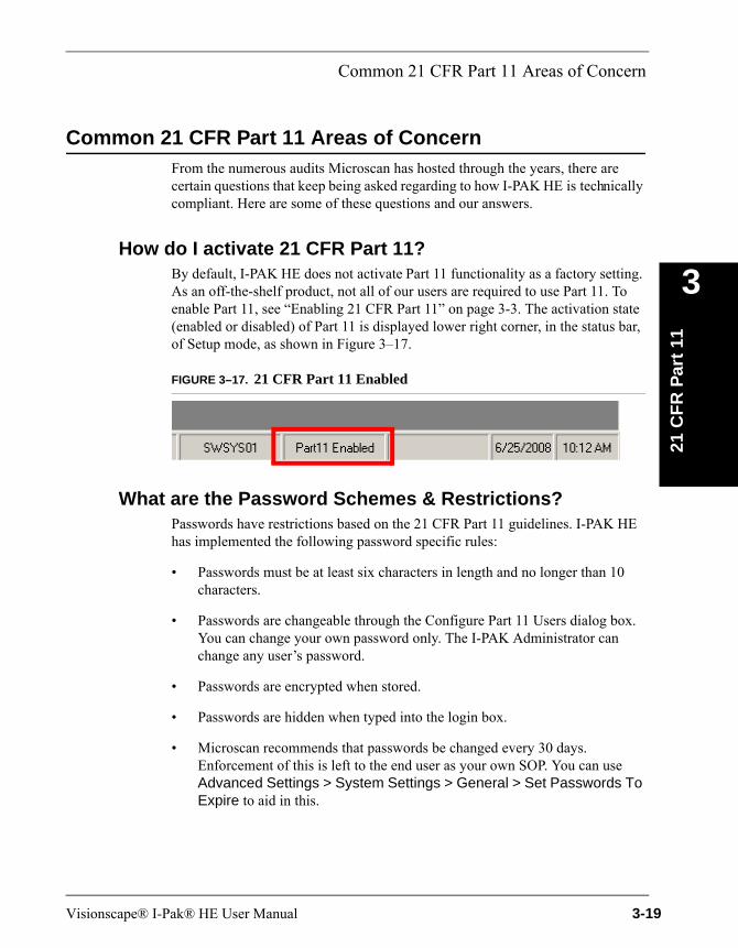
Common 21 CFR Part 11 Areas of Concern
21 C
FR
Par
t 11
3
Common 21 CFR Part 11 Areas of ConcernFrom the numerous audits Microscan has hosted through the years, there are certain questions that keep being asked regarding to how I-PAK HE is technically compliant. Here are some of these questions and our answers.
How do I activate 21 CFR Part 11?By default, I-PAK HE does not activate Part 11 functionality as a factory setting. As an off-the-shelf product, not all of our users are required to use Part 11. To enable Part 11, see “Enabling 21 CFR Part 11” on page 3-3. The activation state (enabled or disabled) of Part 11 is displayed lower right corner, in the status bar, of Setup mode, as shown in Figure 3–17.
FIGURE 3–17. 21 CFR Part 11 Enabled
What are the Password Schemes & Restrictions?Passwords have restrictions based on the 21 CFR Part 11 guidelines. I-PAK HE has implemented the following password specific rules:
• Passwords must be at least six characters in length and no longer than 10 characters.
• Passwords are changeable through the Configure Part 11 Users dialog box. You can change your own password only. The I-PAK Administrator can change any user’s password.
• Passwords are encrypted when stored.
• Passwords are hidden when typed into the login box.
• Microscan recommends that passwords be changed every 30 days. Enforcement of this is left to the end user as your own SOP. You can use Advanced Settings > System Settings > General > Set Passwords To Expire to aid in this.
Visionscape® I-Pak® HE User Manual 3-19
Chapter 3 21 CFR Part 11
• Users entering new passwords are required to enter unique passwords. No two users can have the same password. When changing your password, you cannot change it to what it currently is set to.
• When there is a failed login attempt, the time and date, the user name and the password entered are recorded to a security log and the Audit Trail.
• After a user definable number (1 to 10) of failed login attempts, the user name is suspended from the authorized user list. Only the I-PAK Administrator is able to Restore a User to restore this user account. The suspension of the user is noted on the security log file.
When you create a new user, Supervisor or Programmer, you must specify whether or not that user is authorized to do retraining. By default, this setting is disabled (no signature authority). Existing users will be set to NOT have this Signature Authority feature and, therefore, will NOT be able to approve training. Any existing users in your user group must get a new user name and enable this Signature Authority feature to approve training.
The Signature Authority function has been expanded so that, when person #1 trains the OCV tools or match strings for the Barcode or Data Matrix tools, I-PAK HE checks to make sure that user has signature authority, in addition to continuing to check for a valid user name, password and security level.
How can I prevent my users from getting to the desktop?Advanced Settings > System Settings > General > Enable Desktop allows or prevents users from getting to the desktop. By default, this setting is enabled, meaning you can Alt-Tab and get to the Windows Desktop from I-PAK HE.
For our Part 11 users, this setting should be disabled (unchecked), so that users cannot get to the desktop or taskbar. Disabling the Desktop prevents a user from the following keystrokes: Alt-Tab; Ctrl+Esc (Start Menu and TaskBar); Alt+Esc. This will prevent changes to the System Clock, and will be a deterrent for people who want to use the PC for something other than I-PAK HE.
How safe is the Audit Trail from being compromised?The Audit Trail is an encrypted file. You cannot just open it with a common editor and make sense of the data. Further, the Audit Trail can be made into an Acrobat Reader PDF that can be stored on the local drive or archived to another drive, network or CD. The Audit Trail provides a detailed “who, what, when” log of all I-PAK HE changes. You can view the translated contents of this file as an
3-20 Visionscape® I-Pak® HE User Manual
Common 21 CFR Part 11 Areas of Concern
21 C
FR
Par
t 11
3
authorized user (I-PAK Administrator, Programmer, or Supervisor). Also, you can use the mouse to select some data to be printed. This could be used to show a single Job’s production run from Product ChangeOver to Reconciliation of that Batch records.
How safe are the Jobs files from being compromised?Since the Jobs are binary files, you can only edit them with I-PAK HE. If someone tries to edit a Job with, say, Notepad, and saves those changes, the file will be corrupt and I-PAK HE will not read it in without error. The Jobs are backed up automatically within I-PAK HE so, even if the file gets corrupted, you can easily recover.
How safe are the Configuration & Statistics files from being compromised?
In addition to the read-only property for the support files (Configuration and Statistics files), I-PAK HE hides these files. This offers a more secure method of saving support files that will prevent editing records. The data contained in the Statistics file is completely free from editing because it is written into the encrypted Audit Trail. Additionally, these files can be made into Acrobat Reader PDFs that can be stored on the local drive or archived to another drive, network or CD.
Can this data be saved to a non-editable format?The Audit Trail, the Configuration file and the Statistic file can be made into Acrobat Reader PDFs that can be stored on the local drive or archived to another drive, network or CD.
How do I know who made the last batch or change?The Configuration Data and Statistics files are updated to include the last login name and timestamp to the files. This Statistics information is written to the Audit Trail file as well including that login data.
My company wants the number of login failures to be 3 but I-PAK HE defaults to 5. What can I do?
Advanced Settings > System Settings > General > Set Number of Failed Login Attempts allows a Programmer to define the number of login failure
Visionscape® I-Pak® HE User Manual 3-21
Chapter 3 21 CFR Part 11
attempts. By default, this value is 5; the range is 1 to 10. For more information, see Set Number of Failed Login Attempts on page 6–93.
If I get an alarm on I-PAK HE, how will I know someone saw it?
For Alarms/Overruns, you are required to acknowledge alarms with a login (of Supervisor or higher) to click OK. This transaction is recorded to the Audit Trail file.
What is the date format used inside the Part 11 files?The date format used inside Part 11 files is mm/dd/yyyy hh:mm:ss -- 24-hour format, with leading zeros added for months/dates less than 10.
All this writing to disk; what if I-PAK HE runs out of hard drive space?
I-PAK HE always checks the available disk space before writing the following to disk:
• The Job
• The Audit Trail file
• The Statistics files
• The Configuration files
• Images
3-22 Visionscape® I-Pak® HE User Manual
4
Au
tom
atic
Id
enti
fica
tio
n
4
CHAPTER 4 Automatic Identification
This chapter discusses the following tools for automatic identification:
• “Barcode Reading” on page 4-1
• “Data Matrix Tool” on page 4-18
• “OCRTrainableFont Tool” on page 4-49
Barcode ReadingThe Barcode Tool reads a barcode and converts the data to a string that can be compared to a known string, or exported. The input to the tool consists of an ROI, which types of barcodes to decode, and the search method. The output of the tool will be the decoded string and a status indicating a match with the known string.
Other Steps UsedNone.
Theory of OperationThe Barcode Tool locates and decodes barcodes. It searches the specified ROI for a barcode and attempts to decode it. The Barcode Tool can be trained to set the match string for all types of barcodes. The remaining parameters can only be trained for Pharmacode and will only affect the reading of Pharmacodes.
Visionscape® I-Pak® HE User Manual 4-1
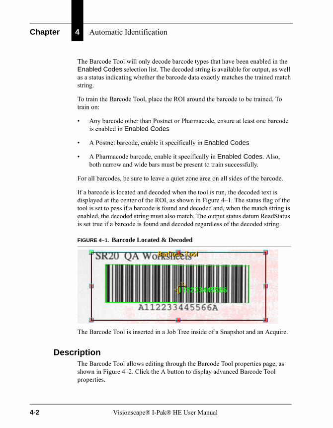
Chapter 4 Automatic Identification
The Barcode Tool will only decode barcode types that have been enabled in the Enabled Codes selection list. The decoded string is available for output, as well as a status indicating whether the barcode data exactly matches the trained match string.
To train the Barcode Tool, place the ROI around the barcode to be trained. To train on:
• Any barcode other than Postnet or Pharmacode, ensure at least one barcode is enabled in Enabled Codes
• A Postnet barcode, enable it specifically in Enabled Codes
• A Pharmacode barcode, enable it specifically in Enabled Codes. Also, both narrow and wide bars must be present to train successfully.
For all barcodes, be sure to leave a quiet zone area on all sides of the barcode.
If a barcode is located and decoded when the tool is run, the decoded text is displayed at the center of the ROI, as shown in Figure 4–1. The status flag of the tool is set to pass if a barcode is found and decoded and, when the match string is enabled, the decoded string must also match. The output status datum ReadStatus is set true if a barcode is found and decoded regardless of the decoded string.
FIGURE 4–1. Barcode Located & Decoded
The Barcode Tool is inserted in a Job Tree inside of a Snapshot and an Acquire.
DescriptionThe Barcode Tool allows editing through the Barcode Tool properties page, as shown in Figure 4–2. Click the A button to display advanced Barcode Tool properties.
4-2 Visionscape® I-Pak® HE User Manual
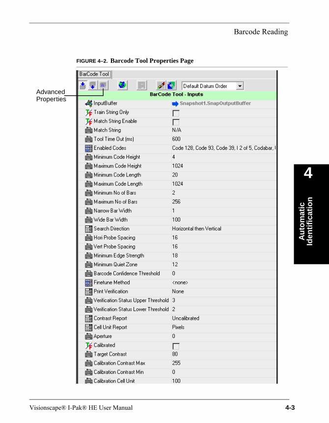
Barcode Reading
Au
tom
atic
Id
enti
fica
tio
n
4
FIGURE 4–2. Barcode Tool Properties Page
AdvancedProperties
Visionscape® I-Pak® HE User Manual 4-3

Chapter 4 Automatic Identification
TABLE 4–1. Links to Property Descriptions
For Information About... Go To...
Aperture page 4–13
Barcode Confidence Threshold page 4–8
BC412 Check Sum page 4–9
BC412 Decode Left Right page 4–9
BC412 Remove Check Sum Display page 4–9
BC412 Start/Stop page 4–9
BC412/QR Code Polarity page 4–9
Calibrated page 4–13
Calibration Cell Unit page 4–13
Calibration Contrast Max page 4–13
Calibration Contrast Min page 4–13
Cell Unit Report page 4–12
Code39 Check Sum page 4–10
Code39 Remove Check Sum Display page 4–10
Contrast Report page 4–12
Enabled Codes page 4–6
Finetune Method page 4–8
Hori. Probe Spacing page 4–7
I2of5 Check Sum page 4–9
I2of5 Remove Check Sum Display page 4–10
Match String page 4–5
Match String Enable page 4–5
Maximum Code Height page 4–7
Maximum Code Length page 4–7
Maximum No. of Bars page 4–7
Minimum Code Height page 4–7
Minimum Code Length page 4–7
Minimum Edge Strength page 4–8
Minimum No. of Bars page 4–7
4-4 Visionscape® I-Pak® HE User Manual

Barcode Reading
Au
tom
atic
Id
enti
fica
tio
n
4
Settings
• Train String Only — After configuring the Barcode tool and setting its Match String Enabled to enabled, when you select the Train button in Train and Tryout, only the match string field will be updated. None of the other barcode parameters will be modified.
• Match String Enable — When enabled, the match string will be compared against the decoded string of a barcode during a run to determine if the step is run successfully. The result datum will be true if a barcode is successfully decoded and the decoded string matches the match string value when this box is checked. During training, the decoded string from the training barcode will be placed in the Match String Value box only when this property is enabled.
• Match String — The entered string will be compared against each decoded string during each run when Enable Match String is enabled. This property will be filled in after a successful train only when Enable Match String is enabled while training.
Default: Empty
Minimum Quiet Zone page 4–8
Narrow Bar Width page 4–7
Output UPC as EAN page 4–9
Print Verification page 4–10
QR Code Finder Pattern Misalignment page 4–10
Search Direction page 4–7
Target Contrast page 4–13
Tool Time Out (ms) page 4–6
Train String Only page 4–5
Verification Status Lower Threshold page 4–12
Verification Status Upper Threshold page 4–12
Vert. Probe Spacing page 4–7
Wide Bar Width page 4–7
TABLE 4–1. Links to Property Descriptions (continued)
For Information About... Go To...
Visionscape® I-Pak® HE User Manual 4-5
Chapter 4 Automatic Identification
• Tool Time Out (ms) — The maximum time to search for a barcode. When a barcode is not found and decoded by this time, this step fails and the program execution continues. After training, if a barcode takes x milliseconds to decode, then the time-out value should be set to more than x milliseconds when Search Direction is Horizontal or Vertical only. The Tool Time Out (ms) value should be at least twice x when Horizontal then Vertical or Vertical then Horizontal parameter is used. When x milliseconds is used as the Tool Time Out (ms) value when Horizontal then Vertical or Vertical then Horizontal parameter is used, each search pass will time out in half of the x milliseconds.
Default: 600 milliseconds (0 milliseconds = no time out)
• Enabled Codes — Only enabled codes will be located within the ROI:
– BC412
– Codabar
– Code 128
– Code 39
– Code 93
– Composite
– I 2 of 5
– Pharma Code
– Postnet
– QR Code
– RSS 14
– RSS Expanded
– RSS Limited
– RSS Stacked
– UPC / EAN
4-6 Visionscape® I-Pak® HE User Manual

Barcode Reading
Au
tom
atic
Id
enti
fica
tio
n
4
– UPC-E
– UPC-Supplemental
• Minimum Code Height — Default: 4; Range: 4 to 1024 pixels.
• Maximum Code Height — Default: 1024 pixels; Range: 4 to 1024 pixels.
• Minimum Code Length — The minimum length of the barcode to be decoded.
Default: 20 pixels
• Maximum Code Length — The maximum length of the barcode to be decoded.
Default: 1024 pixels
• Minimum No. of Bars — Default: 2; Range: 2 to 256 bars.
• Maximum No. of Bars — Default: 256; Range: 2 to 256 bars.
• Narrow Bar Width — Default: 1; Range: 1 to 100 pixels.
• Wide Bar Width — Default: 100; Range: 1 to 100 pixels.
• Search Direction — Specifies the search method used within the ROI:
– Horizontal
– Vertical
– Horizontal then Vertical (default; should work best for most cases)
– Vertical then Horizontal
– Criss Cross
• Hori. Probe Spacing — Sets the spacing in pixels between two horizontal barcode locating probes. When reading short codes such as Postnet, the value should be set to 8.
Default: 16 pixelsRange: 8 to 256 pixels
• Vert. Probe Spacing — Similar to Hori. Probe Spacing, it sets the spacing in pixels between two vertical barcode locating probes. This value
Visionscape® I-Pak® HE User Manual 4-7
Chapter 4 Automatic Identification
does not apply to Postnet or Pharmacode, which are not designed to be read at more than ± 45o.
Default: 16 pixelsRange: 8 to 256 pixels
• Minimum Edge Strength — When the contrast of the barcodes is low, especially for low contrast BC412 images, the edge strength value can be set between 5 and 18 gray scale values. The edge strength can be raised to a higher value when the barcode has very high contrast. With higher edge strength, the tool will ignore most low contrast objects and get to the barcode area more quickly. If the barcode’s contrast is unlikely to change (e.g., when a stable lighting source is employed), the level can be raised to 36 to produce the optimum run performance.
Default: 18Range: 5 to 100
• Minimum Quiet Zone — If, for any reason, the quiet zone is less in the image due to camera set-up restrictions, the Minimum Quiet Zone parameter can be lowered in order for the algorithm to accept shorter space as quiet zone. On the other hand, if the barcode is big in the FOV such that some space between two adjacent bars exceeds the value specified in the Minimum Quiet Zone, then there is a possibility that this space will be detected as possible quiet zone. To avoid this situation, the Minimum Quiet Zone can be increased.
Default: 12 pixelsRange: 5 to 100 pixels
• Barcode Confidence Threshold — For barcodes that do not use checksum (such as Code 39, I 2 of 5, Codabar, and BC412), the threshold value can help reduce potential misdecode. When the value is raised, a certain number of decodes must agree before the decode is declared successful. On the other hand, if the value is set too high, then a normally decodable but imperfect barcode may not be decoded.
Default: 0Range: 0 to 100 (any possible decode is accepted)
• Finetune Method — The only method is Decode Near Center; the Smart Camera tries to read the symbol that is closest to the center of the FOV.
4-8 Visionscape® I-Pak® HE User Manual
Barcode Reading
Au
tom
atic
Id
enti
fica
tio
n
4
• Output UPC as EAN — When enabled, a UPC barcode string will be formatted as an EAN barcode. UPC and EAN are overlapping standards. In the one standard, the leading “0” is implied and not output. In the other standard, all of the characters are displayed. Therefore, if a user in Europe had an EAN code that would be a valid UPC, a user in the United States would default to reporting it as a UPC without the leading “0”. However, if a user in the United States wanted it reported with the leading zero, that user must enable Output UPC as EAN, and the leading zero will be sent as part of the decode string.
• BC412/QR Code Polarity — Sets the polarity of a BC412 or QR Code:
– Auto (Default)
– Light on Dark
– Dark on Light
• BC412 Start/Stop — Enable this property to read a SEMI BC412 barcode with a start and stop pattern. The default is disabled, indicating a non-SEMI BC412 barcode without a start and stop pattern.
• BC412 Check Sum — Enable this property to read a SEMI BC412 barcode with a checksum. The default is disabled, indicating a non-SEMI BC412 barcode without a checksum character.
• BC412 Remove Check Sum Display — When this property is enabled, the checksum character will not be displayed. The default is disabled, meaning that the checksum character will be displayed.
• BC412 Decode Left Right — When not selected, the data will be decoded from right-to-left. This is only useful when Start/Stop is not selected.
Default: Selected (left to right decoding of data)
Note: This mode should not be used for a SEMI BC412 barcode that contains both a start and stop pattern and a checksum character.
• I2of5 Check Sum — Enable this property to read an I2of5 barcode with a checksum. The default is disabled, indicating an I2of5 barcode without a checksum character.
Visionscape® I-Pak® HE User Manual 4-9
Chapter 4 Automatic Identification
• I2of5 Remove Check Sum Display — When this property is enabled, the checksum character will not be displayed. The default is disabled, meaning that the checksum character will be displayed.
• Code39 Check Sum — Enable this property to read an Code 39 barcode with a checksum. The default is disabled, indicating an Code 39 barcode without a checksum character.
• Code39 Remove Check Sum Display — When this property is enabled, the checksum character will not be displayed. The default is disabled, meaning that the checksum character will be displayed.
• QR Code Finder Pattern Misalignment — Sets the QR code finder pattern misalignment parameter.
Default: 0Range: 0 to 6
• Print Verification — Enables Verifier outputs when set to anything other than None:
– ANSI
– None (default)
Print Verification currently supports ANSI Print Verification for Code 128, Code 93, Code 39, I 2 of 5, UPC / EAN, RSS 14, RSS Limited, RSS Expanded, RSS Stacked.
When Print Verification is set to anything other than None, in addition to decoding the barcode, the Barcode Tool also computes the barcode print quality according to the ANSI guideline. To measure the print quality, a total of 10 scans are made to get 10 scan reflectance profiles of the barcode. The scans are approximately equally spaced within the barcode and are made parallel to the length of the barcode. For each scan reflectance profile, the following parameters are graded: Edge Determination, Minimum Reflectance, Reference Decode, Quiet Zone, Minimum Edge Contrast, Symbol Contrast, Modulation, Defects, and Decodability. Each parameter is given a grade as follows:
– A corresponding to a numeric scale of 4.
– B corresponding to a numeric scale of 3.
– C corresponding to a numeric scale of 2.
4-10 Visionscape® I-Pak® HE User Manual

Barcode Reading
Au
tom
atic
Id
enti
fica
tio
n
4
– D corresponding to a numeric scale of 1.
– F corresponding to a numeric scale of 0.
The lowest grade received from these parameters is used as the Overall Profile Grade for the scan profile. The Final Symbol Grade is the simple average of all the overall profile grades using the standard weighting 4 = A, 3 = B, 2 = C, 1 = D, and 0 = F. The average is converted to the Final Symbol Grade:
– 3.5 <= A <= 4.0
– 2.5 <= B < 3.5
– 1.5 <= C < 2.5
– 0.5 <= D < 1.5
– F < 0.5
When Print Verification is set to ANSI, the Final Symbol Grade and its corresponding average score, as well as the ten Overall Profile Grades, are available in Results to Upload. They are represented by BarCode Tool.Final Grade, BarCode Tool.Final Grade Score, and BarCode Tool.Scan X Grade, respectively, where X ranges from 0 to 9.
Outputs include (see the ANSI specification for descriptions):
– Code Type
– Erasure Bits
– Error Bits
– Final Grade
– Number Found
– One X Dim
– Ratio [x] (where x is 0 through 2)
– Read Status
– Scan x Grade (where x is 0 through 9)
Visionscape® I-Pak® HE User Manual 4-11
Chapter 4 Automatic Identification
– Status
– Symbol Height
– Symbol Width
– SymResults
– Text
– Verification Details
– Verification Status
• Verification Status Upper Threshold — Allows you to set the upper threshold at which the printed code is considered good. When the final verification grade is greater than or equal to the value of this property, the code will be considered to be of good quality. This value should always be greater than or equal to the Verification Status Lower Threshold. If it is equal to the Verification Status Lower Threshold, the resulting status will be good (3) or poor (1), with no fair (2) status defined.
Valid Values: 4 to 1
• Verification Status Lower Threshold — Allows you to set the lower threshold at which the printed code is considered fair. When the final verification grade is greater than or equal to the value of this property, the code will be considered to be of fair quality. This value should always be less than or equal to the Verification Status Upper Threshold. If it is equal to the Verification Status Lower Threshold, the resulting status will be good (3) or poor (1), with no fair (2) status defined.
Valid Values: 3 to 1
• Contrast Report — The units that will be used for the reporting of contrast. These are Uncalibrated, Self Calibrated, and Reflectance Calibrated. Reflectance Calibrated is used if values from a Data Matrix tool calibration are available to enter into the Calibration Contrast Max and Calibration Contrast Min parameters that correspond to the Target Contrast of the Calibration Standard.
• Cell Unit Report — The units that will be used for the reporting of cell size and symbol height and width. These are Pixels or Mils. Mils may be used if the value from a Data Matrix tool verification is available to enter into the Calibration Cell Unit parameter.
4-12 Visionscape® I-Pak® HE User Manual
Barcode Reading
Au
tom
atic
Id
enti
fica
tio
n
4
• Aperture — Sets the synthetic aperture size in mils.
Default: 0 for AUTORange: 4 to 20
• Calibrated — Since contrast and pixel to mils calibration are performed with a Data Matrix tool and manually copied to a Barcode tool, this parameter must be manually set to notify the software that it needs to use the calibration parameters.
• Target Contrast— This is the contrast value of the calibration standard used with the Data Matrix tool to generate the calibration parameters.
• Calibration Contrast Max — The value returned from a Data Matrix tool calibration that indicates the pixel brightness that represents white. This must be manually entered for the Barcode tool to report contrast in calibrated units.
• Calibration Contrast Min — The value used by a Data Matrix tool calibration to represent what the Smart Camera sees as absolute black. Because the gains and offset of the Smart Camera may not yield a value of 0 for black, this must be determined experimentally by blocking the light from the Smart Camera and determining the average pixel brightness by moving the cursor across the presented image. This must be manually entered for the Barcode tool to report contrast in calibrated units.
• Calibration Cell Unit — This value is returned from a Data Matrix tool calibration that is the multiplier*100 to convert pixels to mils. This must be entered manually for the Barcode tool to report sizes in calibrated units.
TrainingTo train the Barcode Tool, place the ROI around the barcode to be trained. To train on any barcode other than Postnet or Pharmacode, ensure at least one barcode is enabled in Enabled Codes. To train on a Postnet barcode, enable it specifically in Enabled Codes. To train on a Pharmacode barcode, enable it specifically in Enabled Codes. Also, for Pharmacode, both narrow and wide bars must be present to train successfully.
For all barcodes, be sure to leave a quiet zone area on all sides of the barcode.
Perform the training by clicking Train. When a barcode is successfully found and decoded and Match String Enable is enabled, the match string will be set from that barcode.
Visionscape® I-Pak® HE User Manual 4-13

Chapter 4 Automatic Identification
Results
• Status — The Barcode Tool status is true when a barcode is found and decoded, and the decoded string matches the Match String when Match String Enable is enabled.
• Symbol Height — The Symbol Height is reported if Print Verification is set to ANSI and is reported in Pixels if Cell Unit Report is set to Pixels. If Cell Unit Report is set to Mils, Calibrated is set On, and Calibration Cell Unit is set to the results of a Data Matrix tool calibration; Symbol Height will be reported in mils*100.
• Symbol Width — The Symbol Width is reported if Print Verification is set to ANSI and is reported in Pixels if Cell Unit Report is set to Pixels. If Cell Unit Report is set to Mils, Calibrated is set On, and Calibration Cell Unit is set to the results of a Data Matrix tool calibration; Symbol Width will be reported in mils*100.
• Text — String from the decoded barcode.
• Error Bits — Number of code words in error that are not erasure code words used in error correction algorithm.
• Erasure Bits — Number of code words in error that are erasure code words used in error correction algorithm.
• Code Type — Indicates the type of barcode that is decoded. This is useful when multiple barcodes are enabled in Enabled Codes in order to read different types of barcodes after train. Table 4–2 lists and describes the code types.
TABLE 4–2. Code Types
Code Type Description
16 PDF
32 Code 128
64 Code 93
128 Code 39
256 I 2 of 5
512 Codabar
1024 UPC / EAN
4-14 Visionscape® I-Pak® HE User Manual
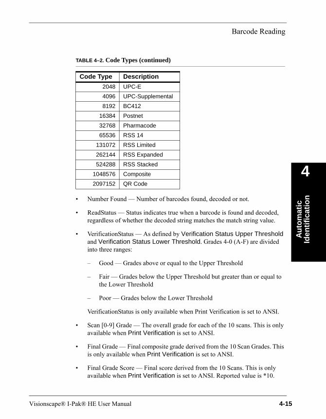
Barcode Reading
Au
tom
atic
Id
enti
fica
tio
n
4
• Number Found — Number of barcodes found, decoded or not.
• ReadStatus — Status indicates true when a barcode is found and decoded, regardless of whether the decoded string matches the match string value.
• VerificationStatus — As defined by Verification Status Upper Threshold and Verification Status Lower Threshold. Grades 4-0 (A-F) are divided into three ranges:
– Good — Grades above or equal to the Upper Threshold
– Fair — Grades below the Upper Threshold but greater than or equal to the Lower Threshold
– Poor — Grades below the Lower Threshold
VerificationStatus is only available when Print Verification is set to ANSI.
• Scan [0-9] Grade — The overall grade for each of the 10 scans. This is only available when Print Verification is set to ANSI.
• Final Grade — Final composite grade derived from the 10 Scan Grades. This is only available when Print Verification is set to ANSI.
• Final Grade Score — Final score derived from the 10 Scans. This is only available when Print Verification is set to ANSI. Reported value is *10.
2048 UPC-E
4096 UPC-Supplemental
8192 BC412
16384 Postnet
32768 Pharmacode
65536 RSS 14
131072 RSS Limited
262144 RSS Expanded
524288 RSS Stacked
1048576 Composite
2097152 QR Code
TABLE 4–2. Code Types (continued)
Code Type Description
Visionscape® I-Pak® HE User Manual 4-15
Chapter 4 Automatic Identification
• One X Dim — The size of the smallest bar in pixels. This is only available when Print Verification is set to ANSI. Reported value is *10.
• Ratio [0] — The widest bar to 1X dimension. This is only available when Print Verification is set to ANSI.
• Ratio [1] — The next widest bar to 1X dimension. This is only available when Print Verification is set to ANSI.
• Ratio [2] — The smallest widest bar to 1X dimension. This is only available when Print Verification is set to ANSI.
• Verification Details — A summary of the grades and values of all parameters for each of the 10 scans. This is only available when Print Verification is set to ANSI.
Note: The reported Modulation, Defects and Decodability are *100. Min Reflectance reported value is *10.
• Sym Results — A summary of locator and decoder statistics such as angle, roi, and symbol type.
I/O SummaryBarcode Tool provides a I/O summary in the Status Bar located at the bottom of the FrontRunner™ window.
Inputs: N/A
Outputs: N/A
Error Messages:The least significant digits of reported Error Messages may be interpreted with the information in Table 4–3.
4-16 Visionscape® I-Pak® HE User Manual
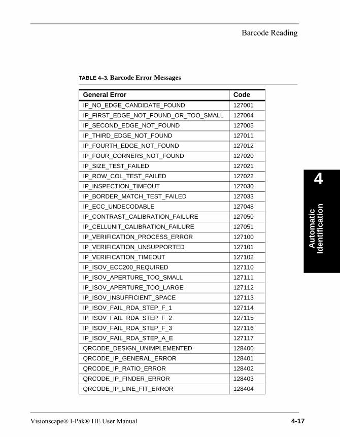
Barcode Reading
Au
tom
atic
Id
enti
fica
tio
n
4
TABLE 4–3. Barcode Error Messages
General Error Code
IP_NO_EDGE_CANDIDATE_FOUND 127001
IP_FIRST_EDGE_NOT_FOUND_OR_TOO_SMALL 127004
IP_SECOND_EDGE_NOT_FOUND 127005
IP_THIRD_EDGE_NOT_FOUND 127011
IP_FOURTH_EDGE_NOT_FOUND 127012
IP_FOUR_CORNERS_NOT_FOUND 127020
IP_SIZE_TEST_FAILED 127021
IP_ROW_COL_TEST_FAILED 127022
IP_INSPECTION_TIMEOUT 127030
IP_BORDER_MATCH_TEST_FAILED 127033
IP_ECC_UNDECODABLE 127048
IP_CONTRAST_CALIBRATION_FAILURE 127050
IP_CELLUNIT_CALIBRATION_FAILURE 127051
IP_VERIFICATION_PROCESS_ERROR 127100
IP_VERIFICATION_UNSUPPORTED 127101
IP_VERIFICATION_TIMEOUT 127102
IP_ISOV_ECC200_REQUIRED 127110
IP_ISOV_APERTURE_TOO_SMALL 127111
IP_ISOV_APERTURE_TOO_LARGE 127112
IP_ISOV_INSUFFICIENT_SPACE 127113
IP_ISOV_FAIL_RDA_STEP_F_1 127114
IP_ISOV_FAIL_RDA_STEP_F_2 127115
IP_ISOV_FAIL_RDA_STEP_F_3 127116
IP_ISOV_FAIL_RDA_STEP_A_E 127117
QRCODE_DESIGN_UNIMPLEMENTED 128400
QRCODE_IP_GENERAL_ERROR 128401
QRCODE_IP_RATIO_ERROR 128402
QRCODE_IP_FINDER_ERROR 128403
QRCODE_IP_LINE_FIT_ERROR 128404
Visionscape® I-Pak® HE User Manual 4-17
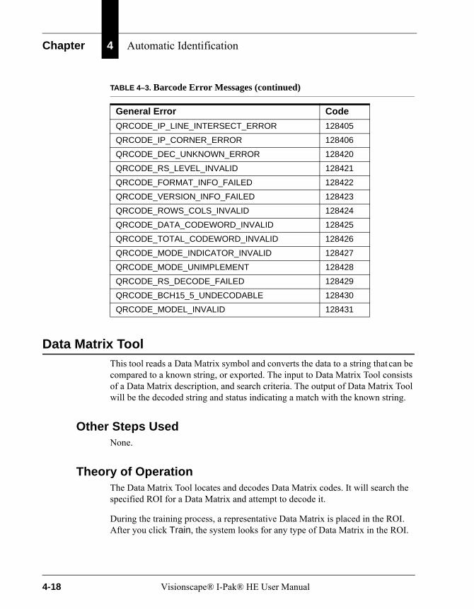
Chapter 4 Automatic Identification
Data Matrix ToolThis tool reads a Data Matrix symbol and converts the data to a string that can be compared to a known string, or exported. The input to Data Matrix Tool consists of a Data Matrix description, and search criteria. The output of Data Matrix Tool will be the decoded string and status indicating a match with the known string.
Other Steps UsedNone.
Theory of OperationThe Data Matrix Tool locates and decodes Data Matrix codes. It will search the specified ROI for a Data Matrix and attempt to decode it.
During the training process, a representative Data Matrix is placed in the ROI. After you click Train, the system looks for any type of Data Matrix in the ROI.
QRCODE_IP_LINE_INTERSECT_ERROR 128405
QRCODE_IP_CORNER_ERROR 128406
QRCODE_DEC_UNKNOWN_ERROR 128420
QRCODE_RS_LEVEL_INVALID 128421
QRCODE_FORMAT_INFO_FAILED 128422
QRCODE_VERSION_INFO_FAILED 128423
QRCODE_ROWS_COLS_INVALID 128424
QRCODE_DATA_CODEWORD_INVALID 128425
QRCODE_TOTAL_CODEWORD_INVALID 128426
QRCODE_MODE_INDICATOR_INVALID 128427
QRCODE_MODE_UNIMPLEMENT 128428
QRCODE_RS_DECODE_FAILED 128429
QRCODE_BCH15_5_UNDECODABLE 128430
QRCODE_MODEL_INVALID 128431
TABLE 4–3. Barcode Error Messages (continued)
General Error Code
4-18 Visionscape® I-Pak® HE User Manual
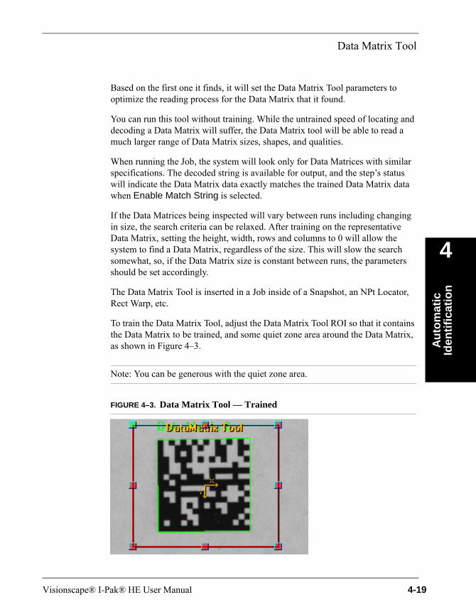
Data Matrix Tool
Au
tom
atic
Id
enti
fica
tio
n
4
Based on the first one it finds, it will set the Data Matrix Tool parameters to optimize the reading process for the Data Matrix that it found.
You can run this tool without training. While the untrained speed of locating and decoding a Data Matrix will suffer, the Data Matrix tool will be able to read a much larger range of Data Matrix sizes, shapes, and qualities.
When running the Job, the system will look only for Data Matrices with similar specifications. The decoded string is available for output, and the step’s status will indicate the Data Matrix data exactly matches the trained Data Matrix data when Enable Match String is selected.
If the Data Matrices being inspected will vary between runs including changing in size, the search criteria can be relaxed. After training on the representative Data Matrix, setting the height, width, rows and columns to 0 will allow the system to find a Data Matrix, regardless of the size. This will slow the search somewhat, so, if the Data Matrix size is constant between runs, the parameters should be set accordingly.
The Data Matrix Tool is inserted in a Job inside of a Snapshot, an NPt Locator, Rect Warp, etc.
To train the Data Matrix Tool, adjust the Data Matrix Tool ROI so that it contains the Data Matrix to be trained, and some quiet zone area around the Data Matrix, as shown in Figure 4–3.
Note: You can be generous with the quiet zone area.
FIGURE 4–3. Data Matrix Tool — Trained
Visionscape® I-Pak® HE User Manual 4-19

Chapter 4 Automatic Identification
The Data Matrix Tool may fail to train when the ROI contains the full image. In this case, reduce the ROI so that it fits just around the Data Matrix and try to Train again. Once the step has been trained, the ROI can be adjusted without retraining. If the tool still fails to train correctly, try the assisted learn training method. When placing the ROI just around the Data Matrix, be sure to leave some white space around the Data Matrix (usually a little greater than the size of an individual cell).
When Assisted Learn is enabled, a second shape appears (Figure 4–4). This shape defines the shape of the Data Matrix to be trained. Adjust the corners of the assisted learn shape so that they are aligned with the corners of the training Data Matrix. Only the ROI is used during the run of Data Matrix Tool. Assisted Learn shape is used only during the training procedure.
FIGURE 4–4. Assisted Learn— Data Matrix Tool
If a Data Matrix is located and decoded from running the Data Matrix Tool, the Data Matrix is outlined and the decoded text displayed above it, as shown in Figure 4–4. The status flag of Data Matrix Tool is set to pass when a Data Matrix is found and decoded and, if the Enable Match String is selected, the decoded string must also match. The output status ReadStatus is set to true when a Data Matrix is found and decoded regardless of the decoded string.
DescriptionData Matrix Tool allows editing through the Data Matrix Tool properties page, as shown in Figure 4–5.
Train ROI
Assisted Learn ROI
4-20 Visionscape® I-Pak® HE User Manual
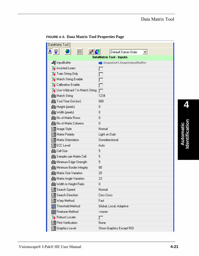
Data Matrix Tool
Au
tom
atic
Id
enti
fica
tio
n
4
FIGURE 4–5. Data Matrix Tool Properties Page
Visionscape® I-Pak® HE User Manual 4-21

Chapter 4 Automatic Identification
TABLE 4–4. Links to Property Descriptions
For Information About... Go To...
Aperture page 4–32
Assisted Learn page 4–23
Calibrated page 4–23
Calibration Cell Unit page 4–32
Calibration Contrast Max page 4–31
Calibration Contrast Min page 4–32
Calibration Enable page 4–23
Cell Size page 4–25
Cell Unit Report page 4–32
Contrast Report page 4–31
ECC Level page 4–25
Finetune Method page 4–28
Graphics Level page 4–31
Height (pixels) page 4–24
Image Style page 4–25
Match String page 4–23
Match String Enable page 4–23
Matrix Angle Variation page 4–26
Matrix Orientation page 4–25
Matrix Polarity page 4–25
Matrix Size Variation page 4–26
Minimum Border Integrity page 4–26
Minimum Edge Strength page 4–26
No. of Matrix Columns page 4–25
No. of Matrix Rows page 4–24
Print Verification page 4–30
Robust Locate page 4–30
Samples per Matrix Cell page 4–26
Search Direction page 4–27
4-22 Visionscape® I-Pak® HE User Manual
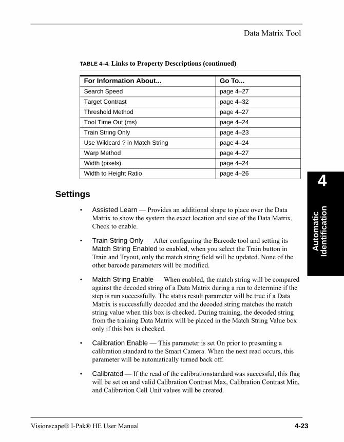
Data Matrix Tool
Au
tom
atic
Id
enti
fica
tio
n
4
Settings• Assisted Learn — Provides an additional shape to place over the Data Matrix to show the system the exact location and size of the Data Matrix. Check to enable.
• Train String Only — After configuring the Barcode tool and setting its Match String Enabled to enabled, when you select the Train button in Train and Tryout, only the match string field will be updated. None of the other barcode parameters will be modified.
• Match String Enable — When enabled, the match string will be compared against the decoded string of a Data Matrix during a run to determine if the step is run successfully. The status result parameter will be true if a Data Matrix is successfully decoded and the decoded string matches the match string value when this box is checked. During training, the decoded string from the training Data Matrix will be placed in the Match String Value box only if this box is checked.
• Calibration Enable — This parameter is set On prior to presenting a calibration standard to the Smart Camera. When the next read occurs, this parameter will be automatically turned back off.
• Calibrated — If the read of the calibration standard was successful, this flag will be set on and valid Calibration Contrast Max, Calibration Contrast Min, and Calibration Cell Unit values will be created.
Search Speed page 4–27
Target Contrast page 4–32
Threshold Method page 4–27
Tool Time Out (ms) page 4–24
Train String Only page 4–23
Use Wildcard ? in Match String page 4–24
Warp Method page 4–27
Width (pixels) page 4–24
Width to Height Ratio page 4–26
TABLE 4–4. Links to Property Descriptions (continued)
For Information About... Go To...
Visionscape® I-Pak® HE User Manual 4-23
Chapter 4 Automatic Identification
• Use Wildcard ? in Match String — When enabled (checked), this can be used in the match string to represent a don't care character, i.e., the character represented by ? can be anything. When disabled, any character ? in the match string is treated as a regular character to be matched.
• Match String — This string will be compared against each decoded string during each run when Match String Enable is selected. This property will be filled in after a successful train only when Match String Enable is selected while training.
Default: Empty
• Tool Time Out (ms) — Maximum time to search for a Data Matrix. When a Data Matrix is not found and decoded by this time, this step fails and the program execution continues. After training, if a Data Matrix takes x milliseconds to decode, then the time-out value should be set to more than x milliseconds when Search Direction is Horizontal or Vertical only. The Tool Time Out (ms) value should be at least twice x when the Horizontal then Vertical or the Vertical then Horizontal parameter is used. When x milliseconds is used as the Tool Time Out (ms) value when Horizontal then Vertical or Vertical then Horizontal parameter is used, each search pass will time out in half of the x milliseconds.
Default: 600 ms (0 = No time out)
• Height (pixels) — The height of the Data Matrix in pixels. This parameter will be filled in after a successful train.
Default: 0Range: 20 to 1024 pixels (0 for Unknown)
• Width (pixels) — The width of the Data Matrix. This property will be filled in after a successful train.
Default: 0 pixelsRange: 20 to 1024 pixels (0 for Unknown)
• No. of Matrix Rows — The number of Data Matrix rows including the borders. It will be filled in after a successful train.
Default: 0Range: 8 to 144 (0 for Unknown)
4-24 Visionscape® I-Pak® HE User Manual
Data Matrix Tool
Au
tom
atic
Id
enti
fica
tio
n
4
• No. of Matrix Columns — The number of Data Matrix columns, similar to the row parameter.
Default: 0Range: 8 to 144 (0 for Unknown)
• Image Style — Options include:
– Mirror — The Data Matrix is viewed as a mirror image.
– Normal — The Data Matrix is viewed as is.
– Auto — By default, set and will be set to Normal.
• Matrix Polarity — Specifies the border and background color orientation:
– Auto — By default, set and will be set accordingly after a successful train.
– Light on Dark — Light cells on a dark background.
– Dark on Light — Dark cells on a light background.
• Matrix Orientation — Selections are Omnidirectional, 0o, 90o, 180o, 270o, 45o, 135o, 225o, and 315o. When the Data Matrix orientation changes from run to run, then Omnidirectional should be used. When the orientation will not change, selecting the correct orientation angle will produce a more robust read. The orientation angle is formed by the x-axis and the bottom of the solid border of the L shape. The angle is positive in a counterclockwise direction. Setting the orientation to a certain degree will not necessarily prevent a Data Matrix of different orientation from being located.
• ECC Level — Specifies the ECC level of the Data Matrix to decode, or Auto for any ECC Level. The options are ECC 200, ECC 140, ECC 100, ECC 80, ECC 50, ECC 0, ECC 250, and SPEC.
Default: Auto
• Cell Size — This is the nominal width and height of a Data Matrix cell in pixels. This value will be set after a successful train.
Default: 6 pixelsRange: 3 to 20 pixels
Visionscape® I-Pak® HE User Manual 4-25
Chapter 4 Automatic Identification
• Samples per Matrix Cell — The width and height of the sample area of a cell. This ranges from 1 to 7 but should not be greater than Cell Size setting.
Default: 5
• Minimum Edge Strength — This value informs the algorithm to search for the edge of a Data Matrix whose intensity exceeds this value.
Default: 18Range: 5 to 100; a setting of 5 will allow a Data Matrix of low contrast to
be located.
• Minimum Border Integrity — Percentage of border that must be intact to consider the Data Matrix valid.
Default: 80Range: 55 to 100
• Matrix Size Variation — The size, representing the height and width of a Data Matrix, is set after training. By default, this parameter is set to 20%, which means the Data Matrix size in run can vary up to 10% from the one used in Train. The number can be reduced to speed up the run process. If the variation in size exceeds 20%, both Height and Width should be set to 0 to disable size constraints.
Default: 20%Range: 0 to 25%
• Matrix Angle Variation — By default, the factor is set to up to 23°. This means that the Data Matrix, in Run Mode, can rotate from the orientation specified by the Matrix Orientation parameter (e.g., 0°, 90°, etc.,) by up to 23° clockwise or counterclockwise. The range can be reduced to increase the reading speed when appropriate. To read a Data Matrix with significant amount of border damage, train the tool on a good label. Set Matrix Size Variation and Angle Variation to 0 and Matrix Orientation to 0°. This will allow the tool to read a badly damaged Data Matrix label as long as its orientation is approximately 0°.
Default: 23°Range: 0 to 180°
• Width to Height Ratio — Matrix width to Data Matrix height ratio scaled by 10. For a width:height ratio of 1.5, enter 15 in this box. This value will be entered after a successful train. This is useful when a tool reads a Data
4-26 Visionscape® I-Pak® HE User Manual
Data Matrix Tool
Au
tom
atic
Id
enti
fica
tio
n
4
Matrix whose size varies more than 10% but the Width to Height Ratio does not change. In this case, set this parameter to match the Data Matrix and set the Height and Width properties to 0. When the Data Matrix changes in size and shape, set this property and Height and Width to 0 after the train.
Default: 10 (1:1 ratio)
• Search Speed — Specifies the method to locate the Data Matrix:
– Normal (Default) — Changing this may improve the speed (at the cost of robustness).
– Overdrive — Increase the locating speed by up to 20% from Normal.
– Turbo — Increase the locating speed by up to 20% from Overdrive.
• Search Direction — Specifies the search method used within the ROI. Changing this parameter requires Tool Time Out (ms) to be modified to ensure the best performance:
– Horizontal — Search for Data Matrix using horizontal probes. The time allowed by Tool Time Out (ms) will be used by horizontal searches.
– Vertical — Search for Data Matrix using vertical probes. The time allowed by Tool Time Out (ms) will be used by vertical searches.
– Horizontal then Vertical — Each search direction will be used up to half of the time allowed by Tool Time Out (ms).
– Vertical then Horizontal — Each search direction will be used up to half of the time allowed by Tool Time Out (ms).
– Criss Cross (Default) — This setting should work best for most cases. This mode uses diagonal probes to optimize the search.
• Warp Method — Specifies the Data Matrix warping method:
– Fast (Default) — Increase the reading speed. Uses approximation to reduce the computation time. This may produce a higher error bit rate than Slow.
– Slow — Enable when receiving a high error bit rate.
• Threshold Method — For dot-peen marks or inkjet printer marks, the spacing between cells may not be accurate. Local or Adaptive cannot
Visionscape® I-Pak® HE User Manual 4-27

Chapter 4 Automatic Identification
replace Global because each is slower and less stable than Global for most of the applications. By default, all three selections are enabled.
– Adaptive — May produce better decode results when the background of the Data Matrix is uneven due to marking or lighting.
– Global — A single threshold value determines whether a cell is dark or light for all cells.
– Local — May yield less error used in the error correction algorithm when Data Matrix rows or columns are not equally spaced.
• Finetune Method — The methods are:
– Position Enhance — Attempts to locate the four corners of the Data Matrix more precisely and to reduce the number of error correction bits used during decoding.
Default: Off
– Intensity Enhance — Overcomes dramatic intensity variation over the Data Matrix border area. For example, certain poorly marked Data Matrix may have some cells that are almost invisible compared to the rest of the cells:
• When disabled, the system may issue a status code indicating a certain edge cannot be found.
• When enabled, the option will help read this type of Data Matrix more consistently.
Default: On
– No Quiet Zone Clutter (default) — Attempts to locate a Data Matrix even if the background is noisy and cluttered. When the Data Matrix is printed on a clean background, enabling this property increases the locating process speed.
Default: Off
– Ignore Single Edges — This property causes the decoder to ignore single edges during the Data Matrix locate process. This speeds up the locate process in the presence of unrelated lines found in the image near the Data Matrix.
4-28 Visionscape® I-Pak® HE User Manual

Data Matrix Tool
Au
tom
atic
Id
enti
fica
tio
n
4
Default: Off
– Finetune Reserved — Reserved for future use.
– Allow Steep Angle — In some Data Matrix reading applications, it is not possible to set up the Smart Camera such that the focal plane is in parallel with the surface of the Data Matrix label. When the focal plane and the label surface form a steep angle, the Data Matrix in the image will have severe geometrical distortion. Use the following steps to read a severely distorted Data Matrix in any orientation:
1. Make sure all Data Matrix Tool settings are in their default state.
2. Select “No Quiet Zone Clutter” and “Allow Steep Angle” for the Finetune method.
3. Select Turbo for the Search Speed.
Now the distorted Data Matrix can be read in Run mode.
Default: Off
– Allow Severe Damage — Enabling this increases the robustness of the software in reading Data Matrices with severe border damage. To use it, first train successfully on a Data Matrix with less damage. Then, enable this option in the Finetune Method to read labels with more damage in Run mode.
Default: Off
– Ensure Within ROI — Enabling this ensures that no Data Matrix is located unless it is fully inside the ROI.
Default: Off
– Allow Outlined Cells — Enabling this helps the algorithm decode a Data Matrix with outlined cells only. In this case, the On and Off cells have little or no contrast but they are separated by edges of the cells.
Default: Off
– Decode Near Center — The Smart Camera tries to read the symbol that is closest to the center of the FOV.
Default: Off
Visionscape® I-Pak® HE User Manual 4-29
Chapter 4 Automatic Identification
• Robust Locate — When enabled, the system will first look for a Data Matrix matching the given specifications. If it fails to find a Data Matrix, the Data Matrix size parameters will be relaxed and the system will try to find the Data Matrix up to two more times.
• Print Verification — Enables Verifier outputs when set to one of the following:
– AIM
– ISO
– IAQG
– DPM
Note: For more information, see “Results” starting on page 4-34.
• Enabled DPM Verification Parameters — If DPM verification is enabled in Print Verification, the parameters to be included for the overall verification grade may be selected. This allows you to ignore a parameter if it is not pertinent to their application. The parameters are:
– Cell Size
– Center Offset
– Size Offset
– Cell Modulation
– Border Match
– Contrast
– Axial Nonuniformity
– Print Growth
– Unused Error Correction
– Distortion Angle
• Verification Status Upper Threshold — Allows you to set the upper threshold at which the printed code is considered good. When the final
4-30 Visionscape® I-Pak® HE User Manual
Data Matrix Tool
Au
tom
atic
Id
enti
fica
tio
n
4
verification grade is greater than or equal to the value of this property, the code will be considered to be of good quality. This value should always be greater than or equal to the Verification Status Lower Threshold. If it is equal to the Verification Status Lower Threshold, the resulting status will be good (3) or poor (1) with no fair (2) status defined.
Valid Values: 4 to 1
• Verification Status Lower Threshold — Allows you to set the lower threshold at which the printed code is considered fair. When the final verification grade is greater than or equal to the value of this property, the code will be considered to be of fair quality. This value should always be less than or equal to the Verification Status Upper Threshold. If it is equal to the Verification Status Lower Threshold, the resulting status will be good (3) or poor (1) with no fair (2) status defined.
Valid Values: 3 to 1
• {parameter} VerStat LoThresh and {parameter} Verstat UpThresh — When DPM verification is enabled in Print Verification, each of the Enabled DPM Verification Parameters will have its own high and low threshold values. The behavior will be the same as for Verification Status Upper Threshold and Verification Status Lower Threshold except applied to classification of the single parameter’s grade. The overall Verification Status for the inspection will be the lowest status of the enable parameters.
• Graphics Level — Selects the amount of graphics displayed at the completion of step execution:
– Show None — When enabled, no graphics are drawn.
– Show Graphics — When enabled, Data Matrix locating graphics and any decoded text will be displayed.
• Contrast Report — The units that will be used for the reporting of contrast. These are Uncalibrated, Self Calibrated, and Reflectance Calibrated. Reflectance Calibrated may be used if values from a Data Matrix tool calibration have been generated by reading a Calibration Standard that corresponds to the entered Target Contrast of the Calibration Standard.
• Calibration Contrast Max — The value returned from a Data Matrix tool calibration that indicates the pixel brightness that represents white.
Visionscape® I-Pak® HE User Manual 4-31
Chapter 4 Automatic Identification
• Calibration Contrast Min — The value used by a Data Matrix tool calibration to represent what the Smart Camera sees as absolute black. Because the gains and offset of the Smart Camera may not yield a value of 0 for black, this must be determined experimentally by blocking the light from the Smart Camera and determining the average pixel brightness by moving the cursor across the presented image. This must be manually entered for the Data Matrix tool to report contrast in calibrated units and entered before calibration is attempted.
• Cell Unit Report — The Units that will be used for the reporting of cell size and symbol height and width. These are Pixels or Mils. Mils may be used if the value of the Calibration Cell Unit is available following a successful calibration.
• Calibration Cell Unit — This value is returned from a Data Matrix tool calibration that is the multiplier*100 to convert pixels to mils.
• Aperture — Sets the synthetic aperture size in mils.
Default: 0 for AUTORange: 4 to 20
• Target Contrast — The contrast value of the calibration standard used with the Data Matrix tool to generate the calibration parameters.
Training
• Normal Training — Place the ROI around the Data Matrix to be trained, and click Train. If a Data Matrix is successfully found and decoded, the trainable set-up parameters (Match String, Height, Width, No. of Matrix Rows, No. of Matrix Columns, Image Style, Matrix Polarity, ECC Level, Cell Size, Minimum Edge Strength, Width to Height Ratio and Threshold Method) will be taken from that Data Matrix, as shown in Figure 4–6. The remainder of the parameters will be set to their defaults to ensure robust reading.
4-32 Visionscape® I-Pak® HE User Manual
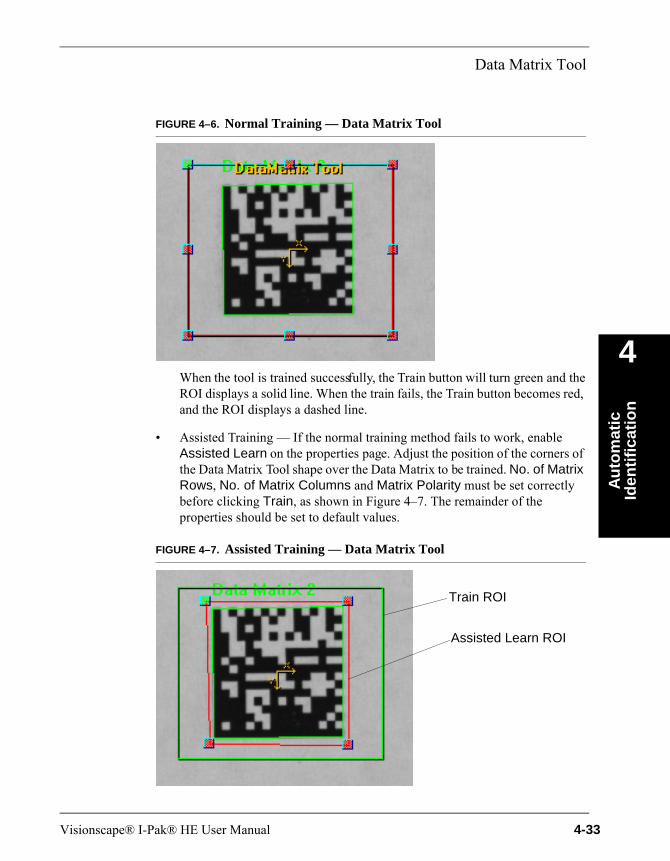
Data Matrix Tool
Au
tom
atic
Id
enti
fica
tio
n
4
FIGURE 4–6. Normal Training — Data Matrix Tool
When the tool is trained successfully, the Train button will turn green and the ROI displays a solid line. When the train fails, the Train button becomes red, and the ROI displays a dashed line.
• Assisted Training — If the normal training method fails to work, enable Assisted Learn on the properties page. Adjust the position of the corners of the Data Matrix Tool shape over the Data Matrix to be trained. No. of Matrix Rows, No. of Matrix Columns and Matrix Polarity must be set correctly before clicking Train, as shown in Figure 4–7. The remainder of the properties should be set to default values.
FIGURE 4–7. Assisted Training — Data Matrix Tool
Train ROI
Assisted Learn ROI
Visionscape® I-Pak® HE User Manual 4-33
Chapter 4 Automatic Identification
• No Training — The Data Matrix tool can operate without training, which will allow a much wider range of Data Matrix codes to be successfully located and decoded.
Results
• Error Code — Reported errors encountered when locating, decoding, calibrating or verifying (see Table 4–5, “Data Matrix Error Messages,” on page 4-40). The least significant digits of reported Error Messages may be interpreted with the information in the table.
• Status — The Data Matrix Tool status is true when a Data Matrix is found and decoded, and the decoded string matches the Match String when Match String Enable is enabled.
• Text — The decoded string found in the Data Matrix.
• Center Point — X,Y location of the center of the Data Matrix.
• Angle — The rotation of the Data Matrix in degrees.
• Number Found — The number of Data Matrices found, decoded or not.
• Read Status — Status indicates true when a Data Matrix is found and decoded, regardless of whether the decoded string matches the match string value.
• SymResults — Contains detailed Data Matrix results.
• Error Bits — The number of invalid bits in the Data Matrix.
• Decoded Image
If Print Verification is set to anything other than None, the following outputs will be produced regardless of the type of verification being performed:
• Symbol Height — The height of the Data Matrix in pixels if Cell Unit Report is set to Pixels. If Cell Unit Report is set to Mils, Calibrated is set On, and Calibration Cell Unit is set to the results of a Data Matrix tool calibration; Symbol Height will be reported in mils*100.
• Symbol Width — The width of the Data Matrix in pixels if Cell Unit Report is set to Pixels. If Cell Unit Report is set to Mils, Calibrated is set On, and
4-34 Visionscape® I-Pak® HE User Manual

Data Matrix Tool
Au
tom
atic
Id
enti
fica
tio
n
4
Calibration Cell Unit is set to the results of a Data Matrix tool calibration; Symbol Width will be reported in mils*100.
• Verification Details — Provides a summary of verification results that is specific to the type of verification selected in Print Verification.
• Verification Overall Grade — Selects the overall lowest grade among the graded parameters for this type of verification.
• Verification Status — As defined by Verification Status Upper and Lower Threshold. Grades 4-0 (A-F) are divided into three ranges.
– Good — Grades above or equal to the Upper Threshold.
– Fair — Grades below the Upper Threshold but greater than or equal to the Lower Threshold.
– Poor — Grades below the Lower Threshold are considered Poor.
Note: For DPM verification, Verification Status is the lowest status found in each of the enabled parameters and each enabled parameter has its own set of threshold values.
Print Verification TypesThe section discusses the following Print Verification types:
• “AIM” starting on page 4-35
• “ISO” starting on page 4-37
• “IAQG” starting on page 4-38
• “DPM” starting on page 4-39
AIM
When you select AIM, in addition to decoding the Data Matrix, the tool also computes the Data Matrix print quality according to the AIM specification. The Data Matrix Tool computes:
– Axial Nonuniformity
– Contrast
Visionscape® I-Pak® HE User Manual 4-35

Chapter 4 Automatic Identification
– Print Growth
Each parameter can be graded as follows:
– A corresponding to a numeric value of 4.
– B corresponding to a numeric value of 3.
– C corresponding to a numeric value of 2.
– D corresponding to a numeric value of 1.
– F corresponding to a numeric value of 0.
The overall print quality grade is the lowest of the four grades:
– Axial Nonuniformity — Measures the difference in average spacing between the center of adjacent cells in the horizontal axis versus that of the vertical axis. A square Data Matrix with the same number of rows and columns typically resembles a rectangular Data Matrix when Axial Nonuniformity is significant as measured per the AIM specification. The grading is:
A when AN <= 0.06B when AN <= 0.08C when AN <= 0.10D when AN <= 0.12F when AN > 0.12
The reported value is *100
– Axial Nonuniformity Grade
– Contrast — Refers to the difference in reflectance between the light and dark cells of the symbol. It is measured according to AIM specification. The Symbol Contrast Grade is given as follows:
A for 70%+ contrastB for 55%+ contrastC for 40%+ contrastD for 20%+ contrastF for less than 20% contrast
4-36 Visionscape® I-Pak® HE User Manual
Data Matrix Tool
Au
tom
atic
Id
enti
fica
tio
n
4
– Contrast Grade — The Contrast Grade is the difference in reflectance (measured by grayscale values) between the light and dark cells of the symbol. The arithmetic mean of the darkest 10% of the pixels and that of the lightest 10% pixels within the Data Matrix area are computed. The Symbol Contrast is the difference of the two means divided by the full gray scale range. The Contrast Grade is given as:
A for 70%+ contrastB for 55%+ contrastC for 40%+ contrastD for 20%+ contrastF for less than 20% contrast
– Print Growth Grade — Print growth measures both X (the direction of the bottom “L” solid border) and Y (the direction of the left “L” solid border) direction and picks the worst as the print growth value for determining the print growth grade.
– Print Growth X — Measurement of the direction of the bottom “L” solid border.
– Print Growth Y — Measurement of the direction of the left “L” solid border.
– UEC Grade — A Data Matrix symbol has fixed error correction capacity. When a Data Matrix is decoded, the Error Correction (used) indicates how much of the error correction capacity is consumed in order to decode the symbol. The more the error correction is used, the less the Unused Error Correction is left within the error correction capacity, which corresponding to poorer print quality of the symbol. The grade is:
A if UEC >= 0.62B if UEC >= 0.50C if UEC >= 0.37D if UEC >= 0.25F if UEC < 0.25
ISO
Outputs include:
– Contrast — Data Matrix contrast 0 to 100%.
Visionscape® I-Pak® HE User Manual 4-37
Chapter 4 Automatic Identification
– Contrast Grade
– Axial Nonuniformity reported as *100
– Axial Nonuniformity Grade
– Print Growth X — Measurement of the direction of the bottom “L” solid border.
– Print Growth Y — Measurement of the direction of the left “L” solid border.
– UEC Grade
– Grid Nonuniformity Grade
– Grid Nonuniformity reported as *100
– Fixed Pattern Damage Grade
– Modulation Grade
– Reference Decode Grade
– Quality 20x Clear Zone
– Cell Size reported as *10
IAQG
Outputs include:
– Cell Fill X
– Cell Fill Y
– Cell Size reported as *10
– Distortion Angle
– Distortion Angle Grade
– Dot Center x (where x is 1 or 2) reported as *10
– Dot Center Grade
– Dot Size x (where x is 1 or 2) reported as *10
4-38 Visionscape® I-Pak® HE User Manual
Data Matrix Tool
Au
tom
atic
Id
enti
fica
tio
n
4
– Dot Size Grade
DPM
Outputs include:
– Axial Nonuniformity reported as *100
– Axial Nonuniformity Grade
– Border Match — Border match 0 to 100%.
– Border Match Grade
– Cell Modulation Grade
– Cell Modulation Off
– Cell Modulation On
– Cell Size reported as *10
– Cell Size Grade
– Center Offset reported as *10
– Center Offset Grade
– Contrast — Data Matrix contrast 0 to 100%.
– Contrast Grade
– Distortion Angle
– Distortion Angle Grade
– Print Growth Grade
– Print Growth X — Measurement of the direction of the bottom “L” solid border.
– Print Growth Y — Measurement of the direction of the left “L” solid border.
– Size Offset reported as *10
– Size Offset Grade
Visionscape® I-Pak® HE User Manual 4-39
Chapter 4 Automatic Identification
– UEC Grade
I/O SummaryData Matrix Tool provides an I/O summary in the Status Bar located at the bottom of the FrontRunner™ window.
Inputs: Cell Size: aaa TimeOut: bbb Robust: FastWarp:
Where: aaa = datum value - not shown if cell size is zero (unknown)bbb = inspection timeout in milliseconds - not shown when
timeout is set to zero (no timeout)Robust = displayed only when Robust Locate is selectedFastWarp = displayed only when FastWarp is selected - not
shown when SlowWarp is selected
Outputs: Error Bits: cc Contrast: dd
Where: cc = number of error bits detected in the Data Matrixdd = contrast of the Data Matrix
Error Messages:The least significant digits of reported Error Messages may be interpreted with the information in Table 4–5.
TABLE 4–5. Data Matrix Error Messages
General Error Code
IP_NO_EDGE_CANDIDATE_FOUND 127001
IP_FIRST_EDGE_NOT_FOUND_OR_TOO_SMALL 127004
IP_SECOND_EDGE_NOT_FOUND 127005
IP_THIRD_EDGE_NOT_FOUND 127011
IP_FOURTH_EDGE_NOT_FOUND 127012
IP_FOUR_CORNERS_NOT_FOUND 127020
IP_SIZE_TEST_FAILED 127021
IP_ROW_COL_TEST_FAILED 127022
IP_INSPECTION_TIMEOUT 127030
IP_BORDER_MATCH_TEST_FAILED 127033
IP_ECC_UNDECODABLE 127048
IP_CONTRAST_CALIBRATION_FAILURE 127050
4-40 Visionscape® I-Pak® HE User Manual

Data Matrix Tool
Au
tom
atic
Id
enti
fica
tio
n
4
IP_CELLUNIT_CALIBRATION_FAILURE 127051
IP_VERIFICATION_PROCESS_ERROR 127100
IP_VERIFICATION_UNSUPPORTED 127101
IP_VERIFICATION_TIMEOUT 127102
IP_ISOV_ECC200_REQUIRED 127110
IP_ISOV_APERTURE_TOO_SMALL 127111
IP_ISOV_APERTURE_TOO_LARGE 127112
IP_ISOV_INSUFFICIENT_SPACE 127113
IP_ISOV_FAIL_RDA_STEP_F_1 127114
IP_ISOV_FAIL_RDA_STEP_F_2 127115
IP_ISOV_FAIL_RDA_STEP_F_3 127116
IP_ISOV_FAIL_RDA_STEP_A_E 127117
QRCODE_DESIGN_UNIMPLEMENTED 128400
QRCODE_IP_GENERAL_ERROR 128401
QRCODE_IP_RATIO_ERROR 128402
QRCODE_IP_FINDER_ERROR 128403
QRCODE_IP_LINE_FIT_ERROR 128404
QRCODE_IP_LINE_INTERSECT_ERROR 128405
QRCODE_IP_CORNER_ERROR 128406
QRCODE_DEC_UNKNOWN_ERROR 128420
QRCODE_RS_LEVEL_INVALID 128421
QRCODE_FORMAT_INFO_FAILED 128422
QRCODE_VERSION_INFO_FAILED 128423
QRCODE_ROWS_COLS_INVALID 128424
QRCODE_DATA_CODEWORD_INVALID 128425
QRCODE_TOTAL_CODEWORD_INVALID 128426
QRCODE_MODE_INDICATOR_INVALID 128427
QRCODE_MODE_UNIMPLEMENT 128428
QRCODE_RS_DECODE_FAILED 128429
QRCODE_BCH15_5_UNDECODABLE 128430
QRCODE_MODEL_INVALID 128431
TABLE 4–5. Data Matrix Error Messages (continued)
General Error Code
Visionscape® I-Pak® HE User Manual 4-41
Chapter 4 Automatic Identification
DMR Verification
DMR Step Output Datums
• AxialNonuniformity value = DoubleDm*0.01
• CellSizeResult value = DoubleDm*0.1
• CenterOffset value = DoubleDm*0.1
• DotCenter1 value = DoubleDm*0.1
• DotCenter2 value = DoubleDm*0.1
• DotSize1 value = DoubleDm*0.1
• DotSize2 value = DoubleDm*0.1
• GridNonuniformity value = DoubleDm*0.01
• SizeOffset value = DoubleDm*0.1
• SymbolHeight value = DoubleDm*0.01
• SymbolWidth value = DoubleDm*0.01
DMR Step Output Datums
• DoubleDm UnusedErrorCorrection value as a number from 0.00 to 1.00 to go along with the existing UnusedErrorCorrectionGrade
• IntDm OvalityGrade with values of 4 through 0 (A, B, C, D, F) for IAQG Verification
• DoubleDm Ovality value as a number from 0.0 to 100.0 for IAQG Verification
• StringDm ECCLevelResult as the decoded value translated to a string because the value returned by the decoder is more specific than the parameter value provided to the decoder as instructions (e.g. AUTO could be used as setting while the decoded result might be ECC 200).
• StringDm VerificationType to report the selected verification type as a string instead of a number that required a translation.
4-42 Visionscape® I-Pak® HE User Manual
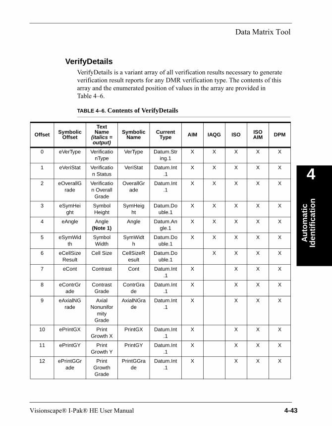
Data Matrix Tool
Au
tom
atic
Id
enti
fica
tio
n
4
VerifyDetailsVerifyDetails is a variant array of all verification results necessary to generate verification result reports for any DMR verification type. The contents of this array and the enumerated position of values in the array are provided in Table 4–6.
TABLE 4–6. Contents of VerifyDetails
Offset Symbolic Offset
Text Name
(italics = output)
Symbolic Name
Current Type AIM IAQG ISO ISO
AIM DPM
0 eVerType VerificationType
VerType Datum.String.1
X X X X X
1 eVeriStat Verification Status
VeriStat Datum.Int.1
X X X X X
2 eOverallGrade
Verification Overall
Grade
OverallGrade
Datum.Int.1
X X X X X
3 eSymHeight
Symbol Height
SymHeight
Datum.Double.1
X X X X X
4 eAngle Angle(Note 1)
Angle Datum.Angle.1
X X X X X
5 eSymWidth
Symbol Width
SymWidth
Datum.Double.1
X X X X X
6 eCellSizeResult
Cell Size CellSizeResult
Datum.Double.1
X X X X
7 eCont Contrast Cont Datum.Int.1
X X X X
8 eContrGrade
Contrast Grade
ContrGrade
Datum.Int.1
X X X X
9 eAxialNGrade
Axial Nonunifor
mity Grade
AxialNGrade
Datum.Int.1
X X X X
10 ePrintGX Print Growth X
PrintGX Datum.Int.1
X X X X
11 ePrintGY Print Growth Y
PrintGY Datum.Int.1
X X X X
12 ePrintGGrade
Print Growth Grade
PrintGGrade
Datum.Int.1
X X X X
Visionscape® I-Pak® HE User Manual 4-43

Chapter 4 Automatic Identification
13 eUECGrade
UEC Grade
UECGrade
Datum.Int.1
X X X X
14 eGridNUGrade
Grid Nonunifor
mity Grade
GridNUGrade
Datum.Int.1
X X
15 eGridNU Grid Nonunifor
mity
GridNU Datum.Int.1
X X
16 eFixPatDamGrade
Fixed Pattern
Damage Grade
FixPatDamGrade
Datum.Int.1
X X
17 eModulGrade
Modulation Grade
ModulGrade
Datum.Int.1
X X
18 eRefDecGrade
Reference Decode
Grade
RefDecGrade
Datum.Int.1
X X
19 eQual20Z Quality 20x Clear
Zone
Qual20Z Datum.Int.1
X X
20 eDotSizeGrade
Dot Size Grade
DotSizeGrade
Datum.Int.1
X
21 eDotSize1
Dot Size 1 DotSize1 Datum.Double.1
X
22 eDotSize2
Dot Size 2 DotSize2 Datum.Double.1
X
23 eDotCentGrade
Dot Center Grade
DotCentGrade
Datum.Int.1
X
24 eDotCent1
Dot Center 1
DotCent1 Datum.Double.1
X
25 eDotCent2
Dot Center 2
DotCent2 Datum.Double.1
X
26 eDistAnglGrade
Distortion Angle Grade
DistAnglGrade
Datum.Int.1
X X
TABLE 4–6. Contents of VerifyDetails (continued)
Offset Symbolic Offset
Text Name
(italics = output)
Symbolic Name
Current Type AIM IAQG ISO ISO
AIM DPM
4-44 Visionscape® I-Pak® HE User Manual
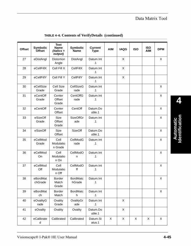
Data Matrix Tool
Au
tom
atic
Id
enti
fica
tio
n
4
27 eDistAngl Distortion Angle
DistAngl Datum.Int.1
X X
28 eCellFillX Cell Fill X CellFillX Datum.Int.1
X
29 eCellFillY Cell Fill Y CellFillY Datum.Int.1
X
30 eCellSizeGrade
Cell Size Grade
CellSizeGrade
Datum.Int.1
X
31 eCentOffGrade
Center Offset Grade
CentOffGrade
Datum.Int.1
X
32 eCentOff Center Offset
CentOff Datum.Double.1
X
33 eSizeOffGrade
Size Offset Grade
SizeOffGrade
Datum.Int.1
X
34 eSizeOff Size Offset
SizeOff Datum.Double.1
X
35 eCellModGrade
Cell Modulation Grade
CellModGrade
Datum.Int.1
X
36 eCellModOn
Cell Modulatio
n On
CellModOn
Datum.Int.1
X
37 eCellModOff
Cell Modulatio
n Off
CellModOff
Datum.Int.1
X
38 eBordMatchGrade
Border Match Grade
BordMatchGrade
Datum.Int.1
X
39 eBordMatch
Border Match
BordMatch
Datum.Int.1
X
40 eOvalityGrade
Ovality Grade
OvalityGrade
Datum.Int.1
X
41 eOvality Ovality Ovality Datum.Double.1
X
42 eCalibrated
Calibrated Calibrated Datum.Status.1
X X X X X
TABLE 4–6. Contents of VerifyDetails (continued)
Offset Symbolic Offset
Text Name
(italics = output)
Symbolic Name
Current Type AIM IAQG ISO ISO
AIM DPM
Visionscape® I-Pak® HE User Manual 4-45
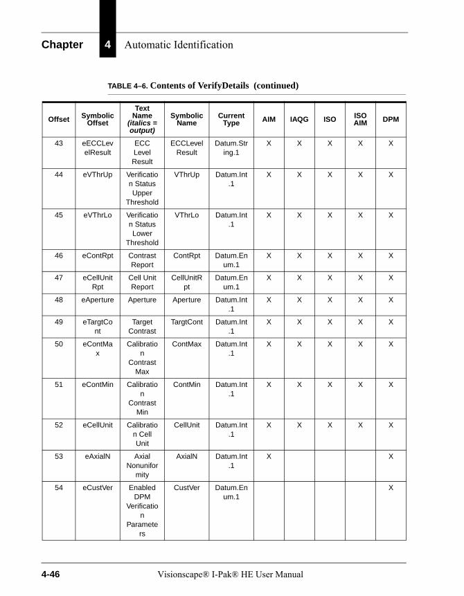
Chapter 4 Automatic Identification
43 eECCLevelResult
ECC Level Result
ECCLevelResult
Datum.String.1
X X X X X
44 eVThrUp Verification Status Upper
Threshold
VThrUp Datum.Int.1
X X X X X
45 eVThrLo Verification Status Lower
Threshold
VThrLo Datum.Int.1
X X X X X
46 eContRpt Contrast Report
ContRpt Datum.Enum.1
X X X X X
47 eCellUnitRpt
Cell Unit Report
CellUnitRpt
Datum.Enum.1
X X X X X
48 eAperture Aperture Aperture Datum.Int.1
X X X X X
49 eTargtCont
Target Contrast
TargtCont Datum.Int.1
X X X X X
50 eContMax
Calibration
Contrast Max
ContMax Datum.Int.1
X X X X X
51 eContMin Calibration
Contrast Min
ContMin Datum.Int.1
X X X X X
52 eCellUnit Calibration Cell Unit
CellUnit Datum.Int.1
X X X X X
53 eAxialN Axial Nonunifor
mity
AxialN Datum.Int.1
X X
54 eCustVer Enabled DPM
Verification
Parameters
CustVer Datum.Enum.1
X
TABLE 4–6. Contents of VerifyDetails (continued)
Offset Symbolic Offset
Text Name
(italics = output)
Symbolic Name
Current Type AIM IAQG ISO ISO
AIM DPM
4-46 Visionscape® I-Pak® HE User Manual
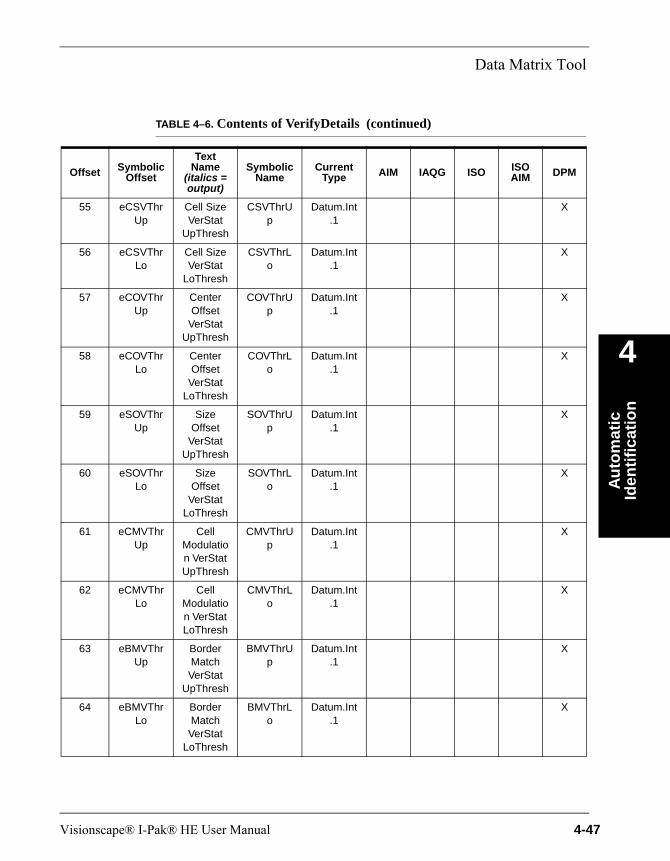
Data Matrix Tool
Au
tom
atic
Id
enti
fica
tio
n
4
55 eCSVThrUp
Cell Size VerStat
UpThresh
CSVThrUp
Datum.Int.1
X
56 eCSVThrLo
Cell Size VerStat
LoThresh
CSVThrLo
Datum.Int.1
X
57 eCOVThrUp
Center Offset
VerStat UpThresh
COVThrUp
Datum.Int.1
X
58 eCOVThrLo
Center Offset
VerStat LoThresh
COVThrLo
Datum.Int.1
X
59 eSOVThrUp
Size Offset
VerStat UpThresh
SOVThrUp
Datum.Int.1
X
60 eSOVThrLo
Size Offset
VerStat LoThresh
SOVThrLo
Datum.Int.1
X
61 eCMVThrUp
Cell Modulation VerStat UpThresh
CMVThrUp
Datum.Int.1
X
62 eCMVThrLo
Cell Modulation VerStat LoThresh
CMVThrLo
Datum.Int.1
X
63 eBMVThrUp
Border Match VerStat
UpThresh
BMVThrUp
Datum.Int.1
X
64 eBMVThrLo
Border Match VerStat
LoThresh
BMVThrLo
Datum.Int.1
X
TABLE 4–6. Contents of VerifyDetails (continued)
Offset Symbolic Offset
Text Name
(italics = output)
Symbolic Name
Current Type AIM IAQG ISO ISO
AIM DPM
Visionscape® I-Pak® HE User Manual 4-47
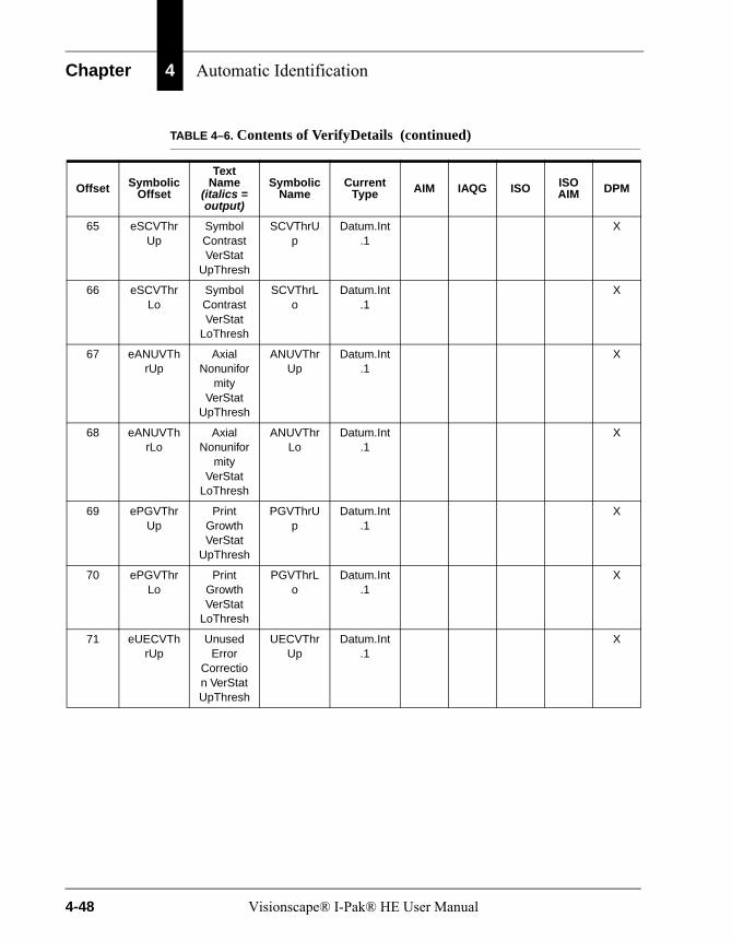
Chapter 4 Automatic Identification
65 eSCVThrUp
Symbol Contrast VerStat
UpThresh
SCVThrUp
Datum.Int.1
X
66 eSCVThrLo
Symbol Contrast VerStat
LoThresh
SCVThrLo
Datum.Int.1
X
67 eANUVThrUp
Axial Nonunifor
mity VerStat
UpThresh
ANUVThrUp
Datum.Int.1
X
68 eANUVThrLo
Axial Nonunifor
mity VerStat
LoThresh
ANUVThrLo
Datum.Int.1
X
69 ePGVThrUp
Print Growth VerStat
UpThresh
PGVThrUp
Datum.Int.1
X
70 ePGVThrLo
Print Growth VerStat
LoThresh
PGVThrLo
Datum.Int.1
X
71 eUECVThrUp
Unused Error
Correction VerStat UpThresh
UECVThrUp
Datum.Int.1
X
TABLE 4–6. Contents of VerifyDetails (continued)
Offset Symbolic Offset
Text Name
(italics = output)
Symbolic Name
Current Type AIM IAQG ISO ISO
AIM DPM
4-48 Visionscape® I-Pak® HE User Manual
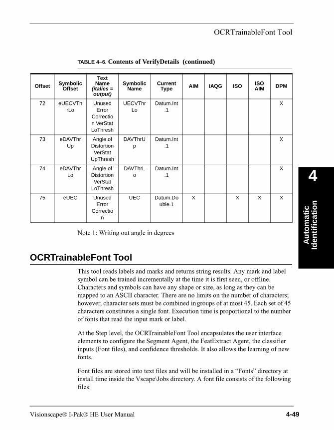
OCRTrainableFont Tool
Au
tom
atic
Id
enti
fica
tio
n
4
Note 1: Writing out angle in degrees
OCRTrainableFont ToolThis tool reads labels and marks and returns string results. Any mark and label symbol can be trained incrementally at the time it is first seen, or offline. Characters and symbols can have any shape or size, as long as they can be mapped to an ASCII character. There are no limits on the number of characters; however, character sets must be combined in groups of at most 45. Each set of 45 characters constitutes a single font. Execution time is proportional to the number of fonts that read the input mark or label.
At the Step level, the OCRTrainableFont Tool encapsulates the user interface elements to configure the Segment Agent, the FeatExtract Agent, the classifier inputs (Font files), and confidence thresholds. It also allows the learning of new fonts.
Font files are stored into text files and will be installed in a “Fonts” directory at install time inside the Vscape\Jobs directory. A font file consists of the following files:
72 eUECVThrLo
Unused Error
Correction VerStat LoThresh
UECVThrLo
Datum.Int.1
X
73 eDAVThrUp
Angle of Distortion VerStat
UpThresh
DAVThrUp
Datum.Int.1
X
74 eDAVThrLo
Angle of Distortion VerStat
LoThresh
DAVThrLo
Datum.Int.1
X
75 eUEC Unused Error
Correction
UEC Datum.Double.1
X X X X
TABLE 4–6. Contents of VerifyDetails (continued)
Offset Symbolic Offset
Text Name
(italics = output)
Symbolic Name
Current Type AIM IAQG ISO ISO
AIM DPM
Visionscape® I-Pak® HE User Manual 4-49
Chapter 4 Automatic Identification
• A fontname.nnd file contains runtime data necessary for OCR to read labels and marks using that Font.
• A fontname.nna file contains the data necessary to incrementally train a font.
• A fontname.nnc file contains the data defining the Font alphabet (ASCII characters) and statistics information necessary to support confidence levels.
By default, a special Font called new (i.e., new.nnd) is always available and is necessary both for creating new fonts and for use at runtime by the OCR tool itself.
The OCRTrainableFont Tool provides both runtime and training capability for the OCR algorithm:
• Runtime — The tool is responsible for reading a mark or label within an ROI using one or more Fonts and reporting results, including the string read and confidence levels for each character read.
• Training — The tool allows the creation of new fonts and allows training and incremental training of existing fonts.
Theory of OperationWhen an OCRTrainableFont Tool is inserted into a Visionscape® Job, the settings that control the behavior of the Segment Agent and the FeatExtract Agent, as well as the font parameter settings, are available on the tool’s property page. From FrontRunner™, when an OCRTrainableFont Tool is present in a Job, a custom interface can edit fonts (for more information, see “OCR Font Training” on page 4-56). The Show Custom Properties button brings up a user interface that can create a new font or incrementally train an existing font. The settings on the property page can modify the way in which the OCRTrainableFont Tool functions:
• If ROI Contains is set to Two or More Characters, see the properties shown in Figure 4–8.
• If ROI Contains is set to Single Character, see the properties shown in Figure 4–9.
4-50 Visionscape® I-Pak® HE User Manual

OCRTrainableFont Tool
Au
tom
atic
Id
enti
fica
tio
n
4
FIGURE 4–8. OCRTrainableFont Tool Properties Page
Visionscape® I-Pak® HE User Manual 4-51
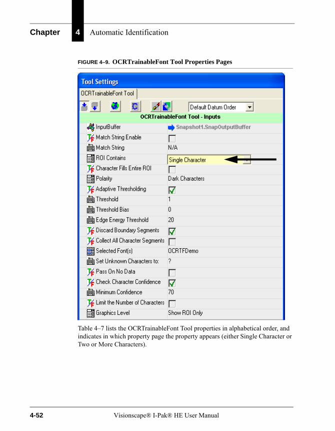
Chapter 4 Automatic Identification
FIGURE 4–9. OCRTrainableFont Tool Properties Pages
Table 4–7 lists the OCRTrainableFont Tool properties in alphabetical order, and indicates in which property page the property appears (either Single Character or Two or More Characters).
4-52 Visionscape® I-Pak® HE User Manual
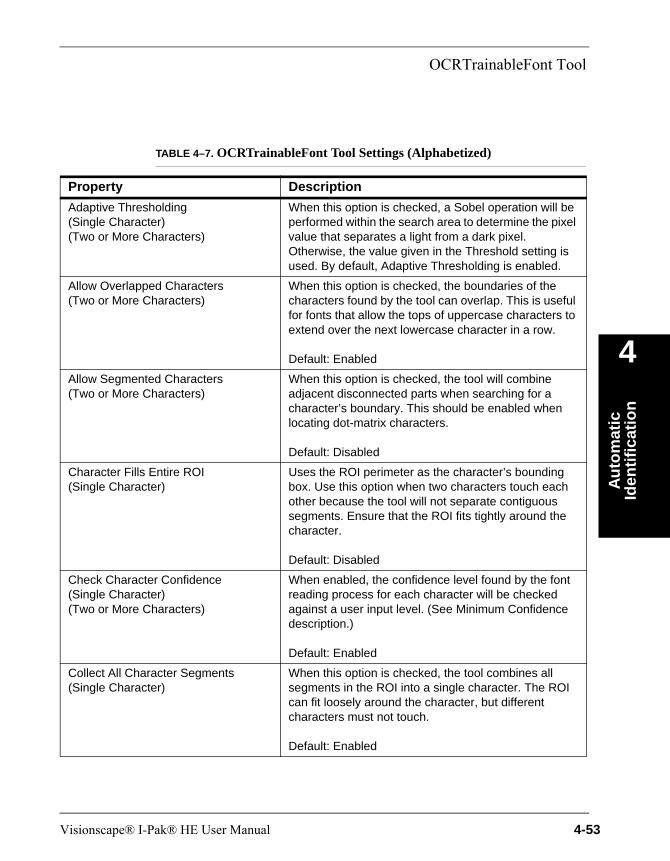
OCRTrainableFont Tool
Au
tom
atic
Id
enti
fica
tio
n
4
TABLE 4–7. OCRTrainableFont Tool Settings (Alphabetized)
Property Description
Adaptive Thresholding(Single Character)(Two or More Characters)
When this option is checked, a Sobel operation will be performed within the search area to determine the pixel value that separates a light from a dark pixel. Otherwise, the value given in the Threshold setting is used. By default, Adaptive Thresholding is enabled.
Allow Overlapped Characters(Two or More Characters)
When this option is checked, the boundaries of the characters found by the tool can overlap. This is useful for fonts that allow the tops of uppercase characters to extend over the next lowercase character in a row.
Default: Enabled
Allow Segmented Characters(Two or More Characters)
When this option is checked, the tool will combine adjacent disconnected parts when searching for a character’s boundary. This should be enabled when locating dot-matrix characters.
Default: Disabled
Character Fills Entire ROI(Single Character)
Uses the ROI perimeter as the character’s bounding box. Use this option when two characters touch each other because the tool will not separate contiguous segments. Ensure that the ROI fits tightly around the character.
Default: Disabled
Check Character Confidence(Single Character)(Two or More Characters)
When enabled, the confidence level found by the font reading process for each character will be checked against a user input level. (See Minimum Confidence description.)
Default: Enabled
Collect All Character Segments(Single Character)
When this option is checked, the tool combines all segments in the ROI into a single character. The ROI can fit loosely around the character, but different characters must not touch.
Default: Enabled
Visionscape® I-Pak® HE User Manual 4-53
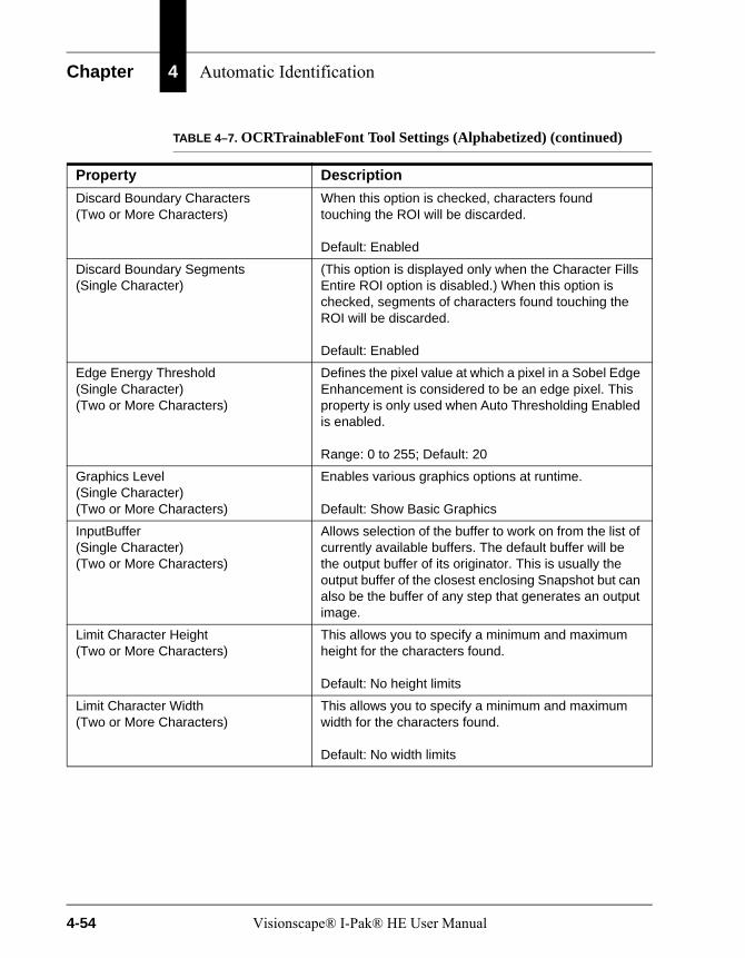
Chapter 4 Automatic Identification
Discard Boundary Characters(Two or More Characters)
When this option is checked, characters found touching the ROI will be discarded.
Default: Enabled
Discard Boundary Segments(Single Character)
(This option is displayed only when the Character Fills Entire ROI option is disabled.) When this option is checked, segments of characters found touching the ROI will be discarded.
Default: Enabled
Edge Energy Threshold(Single Character)(Two or More Characters)
Defines the pixel value at which a pixel in a Sobel Edge Enhancement is considered to be an edge pixel. This property is only used when Auto Thresholding Enabled is enabled.
Range: 0 to 255; Default: 20
Graphics Level(Single Character)(Two or More Characters)
Enables various graphics options at runtime.
Default: Show Basic Graphics
InputBuffer(Single Character)(Two or More Characters)
Allows selection of the buffer to work on from the list of currently available buffers. The default buffer will be the output buffer of its originator. This is usually the output buffer of the closest enclosing Snapshot but can also be the buffer of any step that generates an output image.
Limit Character Height(Two or More Characters)
This allows you to specify a minimum and maximum height for the characters found.
Default: No height limits
Limit Character Width(Two or More Characters)
This allows you to specify a minimum and maximum width for the characters found.
Default: No width limits
TABLE 4–7. OCRTrainableFont Tool Settings (Alphabetized) (continued)
Property Description
4-54 Visionscape® I-Pak® HE User Manual
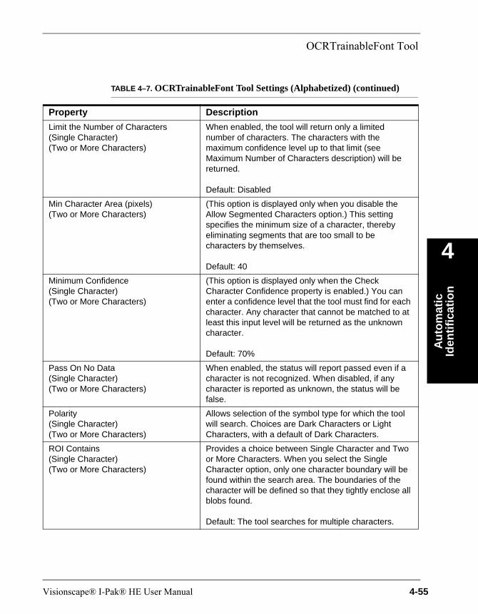
OCRTrainableFont Tool
Au
tom
atic
Id
enti
fica
tio
n
4
Limit the Number of Characters(Single Character)(Two or More Characters)
When enabled, the tool will return only a limited number of characters. The characters with the maximum confidence level up to that limit (see Maximum Number of Characters description) will be returned.
Default: Disabled
Min Character Area (pixels)(Two or More Characters)
(This option is displayed only when you disable the Allow Segmented Characters option.) This setting specifies the minimum size of a character, thereby eliminating segments that are too small to be characters by themselves.
Default: 40
Minimum Confidence(Single Character)(Two or More Characters)
(This option is displayed only when the Check Character Confidence property is enabled.) You can enter a confidence level that the tool must find for each character. Any character that cannot be matched to at least this input level will be returned as the unknown character.
Default: 70%
Pass On No Data(Single Character)(Two or More Characters)
When enabled, the status will report passed even if a character is not recognized. When disabled, if any character is reported as unknown, the status will be false.
Polarity(Single Character)(Two or More Characters)
Allows selection of the symbol type for which the tool will search. Choices are Dark Characters or Light Characters, with a default of Dark Characters.
ROI Contains(Single Character)(Two or More Characters)
Provides a choice between Single Character and Two or More Characters. When you select the Single Character option, only one character boundary will be found within the search area. The boundaries of the character will be defined so that they tightly enclose all blobs found.
Default: The tool searches for multiple characters.
TABLE 4–7. OCRTrainableFont Tool Settings (Alphabetized) (continued)
Property Description
Visionscape® I-Pak® HE User Manual 4-55
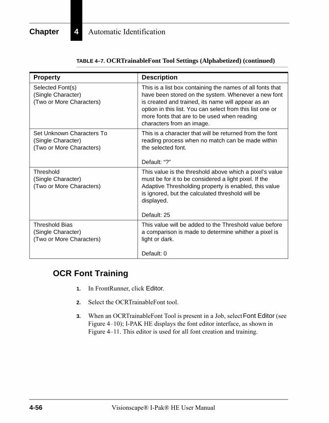
Chapter 4 Automatic Identification
OCR Font Training
1. In FrontRunner, click Editor.
2. Select the OCRTrainableFont tool.
3. When an OCRTrainableFont Tool is present in a Job, select Font Editor (see Figure 4–10); I-PAK HE displays the font editor interface, as shown in Figure 4–11. This editor is used for all font creation and training.
Selected Font(s)(Single Character)(Two or More Characters)
This is a list box containing the names of all fonts that have been stored on the system. Whenever a new font is created and trained, its name will appear as an option in this list. You can select from this list one or more fonts that are to be used when reading characters from an image.
Set Unknown Characters To(Single Character)(Two or More Characters)
This is a character that will be returned from the font reading process when no match can be made within the selected font.
Default: “?”
Threshold(Single Character)(Two or More Characters)
This value is the threshold above which a pixel’s value must be for it to be considered a light pixel. If the Adaptive Thresholding property is enabled, this value is ignored, but the calculated threshold will be displayed.
Default: 25
Threshold Bias(Single Character)(Two or More Characters)
This value will be added to the Threshold value before a comparison is made to determine whither a pixel is light or dark.
Default: 0
TABLE 4–7. OCRTrainableFont Tool Settings (Alphabetized) (continued)
Property Description
4-56 Visionscape® I-Pak® HE User Manual
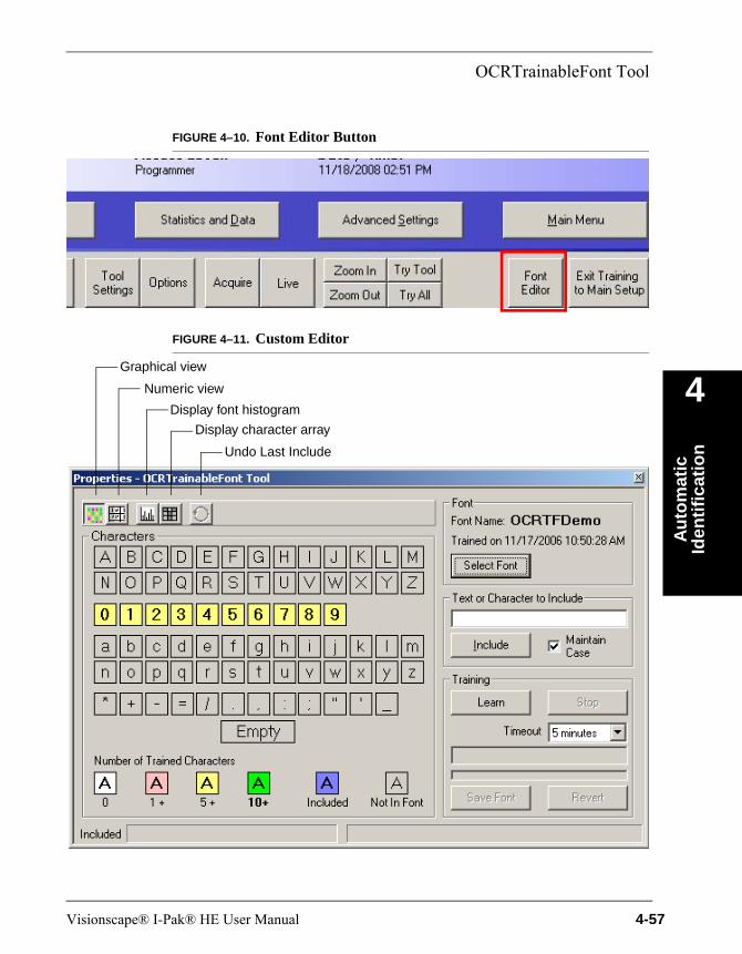
OCRTrainableFont Tool
Au
tom
atic
Id
enti
fica
tio
n
4
FIGURE 4–10. Font Editor Button
FIGURE 4–11. Custom Editor
Undo Last Include
Display character array
Display font histogram
Graphical view
Numeric view
Visionscape® I-Pak® HE User Manual 4-57
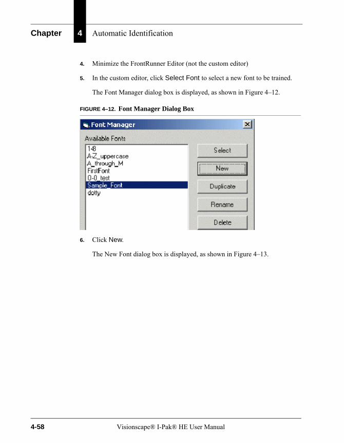
Chapter 4 Automatic Identification
4. Minimize the FrontRunner Editor (not the custom editor)
5. In the custom editor, click Select Font to select a new font to be trained.
The Font Manager dialog box is displayed, as shown in Figure 4–12.
FIGURE 4–12. Font Manager Dialog Box
6. Click New.
The New Font dialog box is displayed, as shown in Figure 4–13.
4-58 Visionscape® I-Pak® HE User Manual
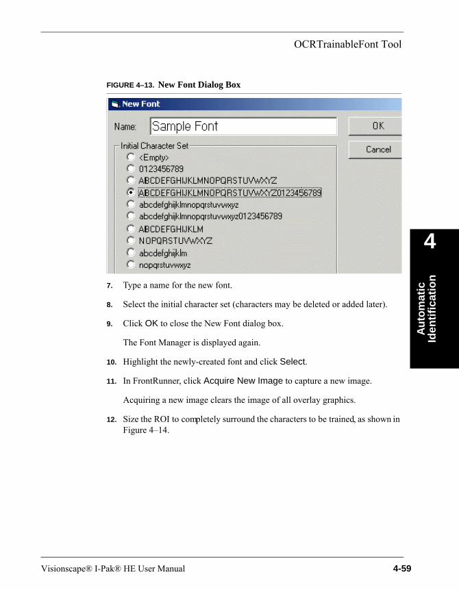
OCRTrainableFont Tool
Au
tom
atic
Id
enti
fica
tio
n
4
FIGURE 4–13. New Font Dialog Box
7. Type a name for the new font.
8. Select the initial character set (characters may be deleted or added later).
9. Click OK to close the New Font dialog box.
The Font Manager is displayed again.
10. Highlight the newly-created font and click Select.
11. In FrontRunner, click Acquire New Image to capture a new image.
Acquiring a new image clears the image of all overlay graphics.
12. Size the ROI to completely surround the characters to be trained, as shown in Figure 4–14.
Visionscape® I-Pak® HE User Manual 4-59
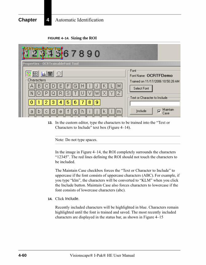
Chapter 4 Automatic Identification
FIGURE 4–14. Sizing the ROI
13. In the custom editor, type the characters to be trained into the “Text or Characters to Include” text box (Figure 4–14).
Note: Do not type spaces.
In the image in Figure 4–14, the ROI completely surrounds the characters “12345”. The red lines defining the ROI should not touch the characters to be included.
The Maintain Case checkbox forces the “Text or Character to Include” to uppercase if the font consists of uppercase characters (ABC). For example, if you type “klm”, the characters will be converted to “KLM” when you click the Include button. Maintain Case also forces characters to lowercase if the font consists of lowercase characters (abc).
14. Click Include.
Recently included characters will be highlighted in blue. Characters remain highlighted until the font is trained and saved. The most recently included characters are displayed in the status bar, as shown in Figure 4–15
4-60 Visionscape® I-Pak® HE User Manual
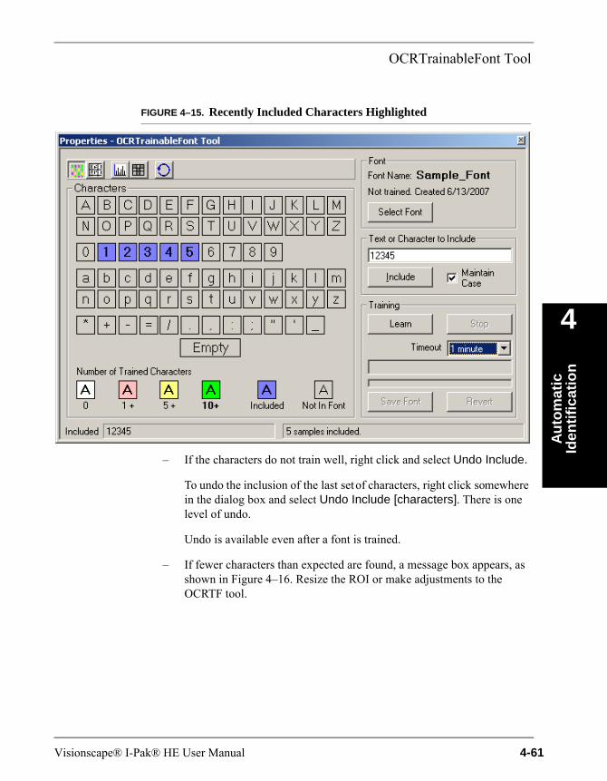
OCRTrainableFont Tool
Au
tom
atic
Id
enti
fica
tio
n
4
FIGURE 4–15. Recently Included Characters Highlighted
– If the characters do not train well, right click and select Undo Include.
To undo the inclusion of the last set of characters, right click somewhere in the dialog box and select Undo Include [characters]. There is one level of undo.
Undo is available even after a font is trained.
– If fewer characters than expected are found, a message box appears, as shown in Figure 4–16. Resize the ROI or make adjustments to the OCRTF tool.
Visionscape® I-Pak® HE User Manual 4-61
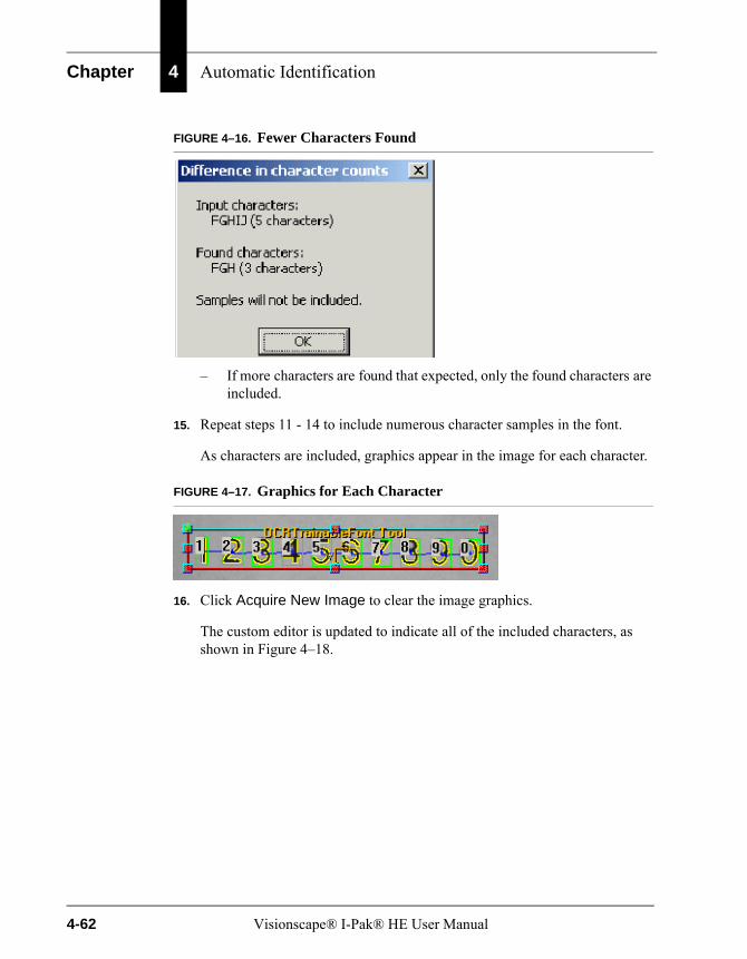
Chapter 4 Automatic Identification
FIGURE 4–16. Fewer Characters Found
– If more characters are found that expected, only the found characters are included.
15. Repeat steps 11 - 14 to include numerous character samples in the font.
As characters are included, graphics appear in the image for each character.
FIGURE 4–17. Graphics for Each Character
16. Click Acquire New Image to clear the image graphics.
The custom editor is updated to indicate all of the included characters, as shown in Figure 4–18.
4-62 Visionscape® I-Pak® HE User Manual
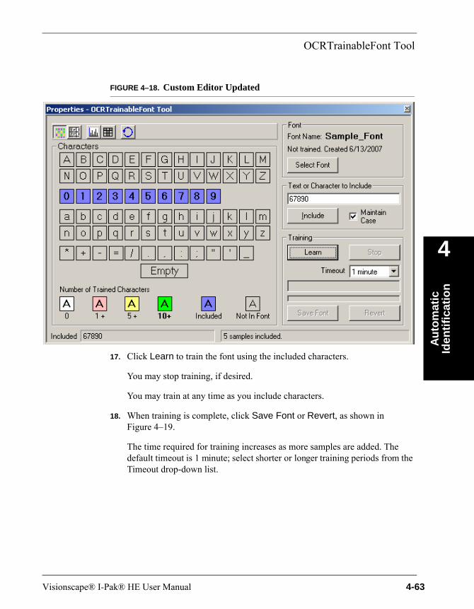
OCRTrainableFont Tool
Au
tom
atic
Id
enti
fica
tio
n
4
FIGURE 4–18. Custom Editor Updated
17. Click Learn to train the font using the included characters.
You may stop training, if desired.
You may train at any time as you include characters.
18. When training is complete, click Save Font or Revert, as shown in Figure 4–19.
The time required for training increases as more samples are added. The default timeout is 1 minute; select shorter or longer training periods from the Timeout drop-down list.
Visionscape® I-Pak® HE User Manual 4-63
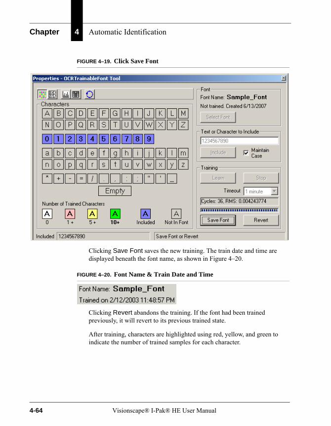
Chapter 4 Automatic Identification
FIGURE 4–19. Click Save Font
Clicking Save Font saves the new training. The train date and time are displayed beneath the font name, as shown in Figure 4–20.
FIGURE 4–20. Font Name & Train Date and Time
Clicking Revert abandons the training. If the font had been trained previously, it will revert to its previous trained state.
After training, characters are highlighted using red, yellow, and green to indicate the number of trained samples for each character.
4-64 Visionscape® I-Pak® HE User Manual

OCRTrainableFont Tool
Au
tom
atic
Id
enti
fica
tio
n
4
FIGURE 4–21. After Training
When the mouse pointer rests over a character, a tool tip pops up indicating the number of trained samples for the character. In Figure 4–21, the tool tip shows that six samples have been trained for the character “A”.
19. Defocus the lens slightly and repeat steps 11 - 18.
A font should be trained using samples that vary in quality. When fewer samples than desired are available, the set of samples can be re-used several times during training.
To re-use the character set after the first round of training, defocus the lens slightly to render the characters a bit fuzzy. If the lens is not easily accessible, use image processing to change the appearance of the characters.
This method simulates the variability expected in large sample sets of characters.
Visionscape® I-Pak® HE User Manual 4-65
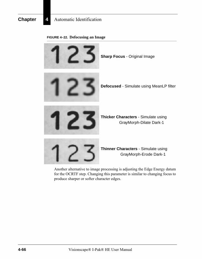
Chapter 4 Automatic Identification
FIGURE 4–22. Defocusing an Image
Another alternative to image processing is adjusting the Edge Energy datum for the OCRTF step. Changing this parameter is similar to changing focus to produce sharper or softer character edges.
Sharp Focus - Original Image
Defocused - Simulate using MeanLP filter
Thicker Characters - Simulate using
Thinner Characters - Simulate using
GrayMorph-Dilate Dark-1
GrayMorph-Erode Dark-1
4-66 Visionscape® I-Pak® HE User Manual

OCRTrainableFont Tool
Au
tom
atic
Id
enti
fica
tio
n
4
Numeric View
FIGURE 4–23. Numeric View Button
After you click Numeric View, the constants associated with each character sample are displayed in a grid, as shown in Figure 4–24.
FIGURE 4–24. Constants for Character Samples
Committed Samples corresponds to included characters.
Numeric View
Graphical View
Visionscape® I-Pak® HE User Manual 4-67
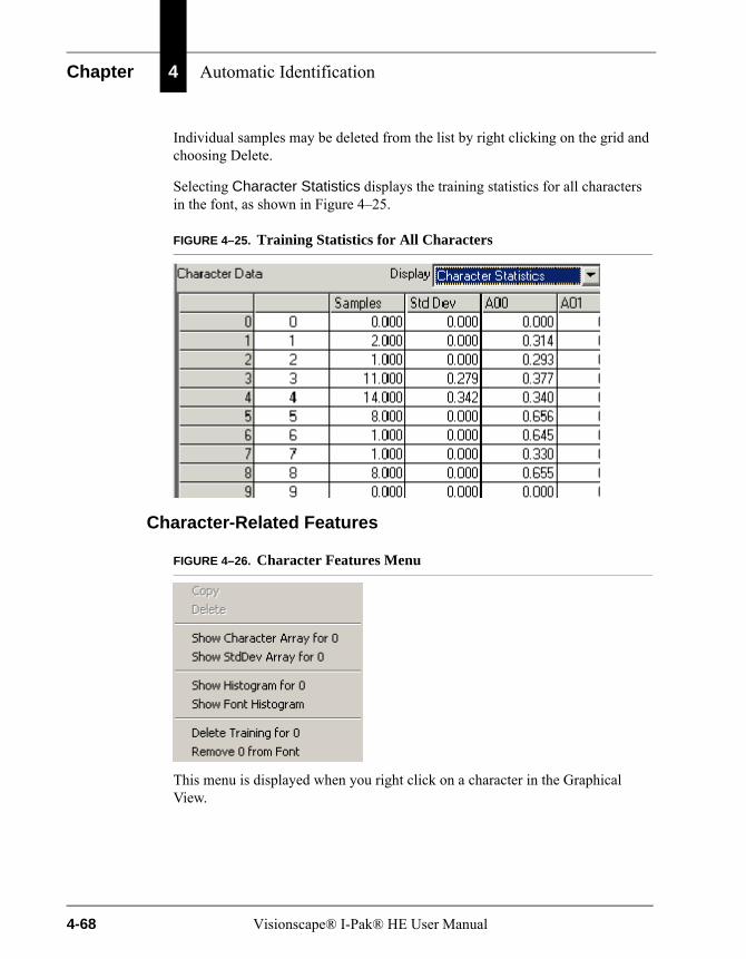
Chapter 4 Automatic Identification
Individual samples may be deleted from the list by right clicking on the grid and choosing Delete.
Selecting Character Statistics displays the training statistics for all characters in the font, as shown in Figure 4–25.
FIGURE 4–25. Training Statistics for All Characters
Character-Related Features
FIGURE 4–26. Character Features Menu
This menu is displayed when you right click on a character in the Graphical View.
4-68 Visionscape® I-Pak® HE User Manual
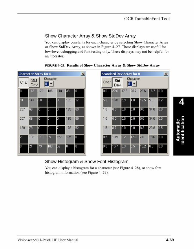
OCRTrainableFont Tool
Au
tom
atic
Id
enti
fica
tio
n
4
Show Character Array & Show StdDev ArrayYou can display constants for each character by selecting Show Character Array or Show StdDev Array, as shown in Figure 4–27. These displays are useful for low-level debugging and font testing only. These displays may not be helpful for an Operator.
FIGURE 4–27. Results of Show Character Array & Show StdDev Array
Show Histogram & Show Font HistogramYou can display a histogram for a character (see Figure 4–28), or show font histogram information (see Figure 4–29).
Visionscape® I-Pak® HE User Manual 4-69
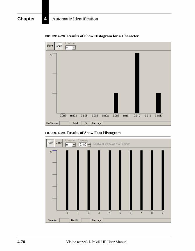
Chapter 4 Automatic Identification
FIGURE 4–28. Results of Show Histogram for a Character
FIGURE 4–29. Results of Show Font Histogram
4-70 Visionscape® I-Pak® HE User Manual

OCRTrainableFont Tool
Au
tom
atic
Id
enti
fica
tio
n
4
Delete Training & Remove from FontThe Delete Training feature removes all trained samples for a character from the font. This feature is useful if a particular character should be retrained by itself. You will be prompted regarding deleting all samples for a character.
Remove from Font deletes all training for a character and removes it completely from the font. You will be prompted regarding excluding the character from the font.
Training Tips
• The camera field of view (FOV) should be configured so that the characters read by the OCRTrainableFont tool have a character width of 25 pixels or larger.
• Given an initial set of sample parts, divided the samples into two subsets. Use one subset for training and the other subset for reading tests.
• For OCRTrainableFont, the image background should be relatively free of noise.
• Be certain to train using samples of varying quality. The samples should be representative of the character print/mark quality expected during production runs of the printed characters.
• Train frequently. A font may be trained at any time.
• If the value of the RMS error increases significantly after a new training cycle, consider deleting recently added samples.
• Changes should be made to the trained font whenever the Smart Camera position is moved. If the change in camera position or lens focus is minor, it may be necessary to add no more than a few characters samples.
• Note that certain characters are more prone to be confused for other characters. Examples include B/8, G/6, and numeral 0/ letter O. During testing, confirm that these characters are distinguished from one another accurately.
• If the camera lens is inaccessible for defocusing, use software methods to simulate variations in character quality.
• Note that each OCRTF step can use multiple trained fonts.
Visionscape® I-Pak® HE User Manual 4-71
Chapter 4 Automatic Identification
• If training takes longer than a minute, try dividing a font into two or more smaller fonts. Click Select Font to display the Font Manager dialog box, then click Duplicate to create a copy of the font. Remove characters from the font copy to reduce the size of the character set. A font with characters A - Z can be split into fonts with A - M and N - Z. Make sure all required fonts are selected in the OCRTrainableFont Tool.
• Until Save Font is clicked, font changes may be abandoned. Close the OCRTF Training dialog box and click No when prompted to save changes.
Tips for Marking OCR Fonts
• Use either the numeral 0 or the letter O, but not both. If a human operator has trouble distinguishing characters quickly, the vision system will also have difficulty.
• Unlike machine-readable codes such as Data Matrix, OCR does not have built-in error correction. Misreads are possible. For example, “813” may be reported as “B13”. If possible, include a checksum character in the printed text.
Results
• Status — Set to true after a successful execution of the step.
• Number of Characters Found — Total number of character objects found, whether or not they were successfully decoded.
• Output String — The set of characters found within the ROI placed in order from the top left most character and scanning to the right, then down. Characters that are found but not decoded will be represented by the character defined by Set Unknown Characters To.
• Minimum Character Confidence — The lowest match level of the characters successfully decoded.
• Mean Character Confidence — The mean match level of the characters successfully decoded. This excludes the confidence level of any characters that were excluded by the 'Minimum Confidence' parameter.
• Maximum Character Confidence — The highest match level of the characters successfully decoded.
4-72 Visionscape® I-Pak® HE User Manual

OCRTrainableFont Tool
Au
tom
atic
Id
enti
fica
tio
n
4
• OCRTF Character Results — Contains a vector of the character confidence values for the successfully decoded characters only. The results are in the order of the characters in the output string skipping unknown characters.
Visionscape® I-Pak® HE User Manual 4-73

Chapter 4 Automatic Identification
4-74 Visionscape® I-Pak® HE User Manual

5
OC
V R
efer
ence
5
CHAPTER 5 OCV Reference
This chapter provides Optical Character Verification tool details.
OverviewVisionscape® I-PAK® HE has three options for Optical Character Verification (OCV), each of which has an appropriate use:
• “OCVFont Tool” on page 5-37
• “OCVRuntimeTool” on page 5-45
• “OCVFontless Tool” on page 5-55
This chapter outlines each of these tools along with their supporting steps.
OCV InspectionThe OCV Tools and their supporting steps inspect codes such as component ID and Date/Lot. The print may be either pre-print or On-line. Individual printed features are referred to as symbols. The OCV inspection methods inspect the quality of the individual printed symbols. Quality checks include:
• Contrast — Contrast refers to the difference between symbol and background. A contrast value is calculated for the symbol and compared to a user-selectable contrast minimum. The symbol fails if the calculated value is less than the minimum.
Visionscape® I-Pak® HE User Manual 5-1
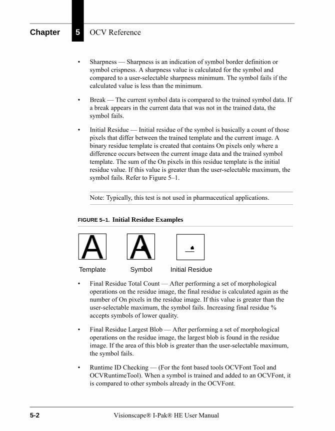
Chapter 5 OCV Reference
• Sharpness — Sharpness is an indication of symbol border definition or symbol crispness. A sharpness value is calculated for the symbol and compared to a user-selectable sharpness minimum. The symbol fails if the calculated value is less than the minimum.
• Break — The current symbol data is compared to the trained symbol data. If a break appears in the current data that was not in the trained data, the symbol fails.
• Initial Residue — Initial residue of the symbol is basically a count of those pixels that differ between the trained template and the current image. A binary residue template is created that contains On pixels only where a difference occurs between the current image data and the trained symbol template. The sum of the On pixels in this residue template is the initial residue value. If this value is greater than the user-selectable maximum, the symbol fails. Refer to Figure 5–1.
Note: Typically, this test is not used in pharmaceutical applications.
FIGURE 5–1. Initial Residue Examples
• Final Residue Total Count — After performing a set of morphological operations on the residue image, the final residue is calculated again as the number of On pixels in the residue image. If this value is greater than the user-selectable maximum, the symbol fails. Increasing final residue % accepts symbols of lower quality.
• Final Residue Largest Blob — After performing a set of morphological operations on the residue image, the largest blob is found in the residue image. If the area of this blob is greater than the user-selectable maximum, the symbol fails.
• Runtime ID Checking — (For the font based tools OCVFont Tool and OCVRuntimeTool). When a symbol is trained and added to an OCVFont, it is compared to other symbols already in the OCVFont.
Template Symbol Initial Residue
5-2 Visionscape® I-Pak® HE User Manual
OCV Inspection
OC
V R
efer
ence
5
Note: OCVFont boxes must be the same size in order to utilize Runtime ID tests.
If the two symbols being compared are found to be similar, tests are set up that verify that the correct symbol is present at runtime. If it cannot be determined that the correct symbol is present at runtime, the symbol fails the inspection.
Additional Filters
• Character Expansions are useful when dealing with print from a dot matrix printer or any print that is broken up in segments. The broken print is filtered so that it becomes solid by expanding the segments until they come together. Dilations expand each segment. Then, erosions decrease the size of the character in every direction except the direction in which the segments have connected. Dilations and erosions work together to make the segments solid without making the character fatter.
• Filter Bright Defects are useful when dust or other material settles on the print and appears brighter than the print in the image. This filter eliminates the bright specks and allows proper inspection of the print.
Note: Typically, this test is not used in pharmaceutical applications.
Brief Descriptions
• OCVFont — An OCVFont step is a container of one or more FontSymbol steps. The OCVFont contains a default FontSymbol that is used only for setting default parameters (parameters that any FontSymbol will inherit when inserted into the OCVFont). One or more OCVFonts are required for font-based OCV. OCVFonts are created and modified using the Custom Properties dialog box of the OCVFont Tool or OCVRuntimeTool. OCVFonts are stored separately from the inspection Job file in the Vscape\Jobs\Fonts folder.
• FontSymbol — A FontSymbol is a collection of template images, settings, and tolerances that inspect a character or logo at runtime.
Visionscape® I-Pak® HE User Manual 5-3
Chapter 5 OCV Reference
• OCVFont Tool — An OCVFont Tool uses an OCVFont to learn the layout, and determine which characters from the OCVFont are in which locations in the FOV. Once the layout is learned, the OCVFont Tool expects to find these symbols at the same locations during inspection. It uses the data from the FontSymbols in the OCVFont to verify the quality of the characters being inspected.
• OCVRuntimeTool — An OCVRuntimeTool uses an OCVFont (called the Master Font) to learn the layout, and determine which characters from the OCVFont are in which locations in the FOV. Once the layout is learned, the OCVRuntimeTool creates a new OCVFont (called a Runtime Font) by training a new FontSymbol at each layout position, using the current image data. The OCVRuntimeTool expects to find the symbols at the same locations during inspection. It uses the data from the Runtime Font to verify the quality of the characters being inspected. The OCVRuntimeTool compensates for day-to-day changes in On-line print and helps minimize false rejects. The OCVRuntimeTool can be used when inspecting Date/Lot codes.
• OCVFontlessTool — An OCVFontless Tool does not require an OCVFont. Instead, it determines the location of characters in the FOV using a blob-analysis technique. It then stores training data for each character location as an OCVSymbolStep. The OCVFontless Tool expects to find the symbols at the same locations during inspection. It uses the trained data to verify the quality of the characters being inspected. The OCVFontless Tool checks symbol quality and not symbol correctness. The OCVFontless Tool can be used on Date/Lot codes when only symbol quality is a concern. Do not use the OCVFontless Tool to inspect Component ID codes. Table 5–1 contains usage hints.
Note: When placing the ROI around the code to inspect, be sure to leave quiet zone area on either side of the code.
5-4 Visionscape® I-Pak® HE User Manual
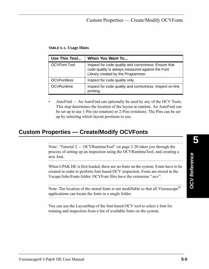
Custom Properties — Create/Modify OCVFonts
OC
V R
efer
ence
5
• AutoFind — An AutoFind can optionally be used by any of the OCV Tools. This step determines the location of the layout at runtime. An AutoFind can be set up to use 1-Pin (no rotation) or 2-Pins (rotation). The Pins can be set up by selecting which layout positions to use.
Custom Properties — Create/Modify OCVFonts
Note: “Tutorial 2 — OCVRuntimeTool” on page 2-20 takes you through the process of setting up an inspection using the OCVRuntimeTool, and creating a new font.
When I-PAK HE is first loaded, there are no fonts on the system. Fonts have to be created in order to perform font based OCV inspection. Fonts are stored in the Vscape\Jobs\Fonts folder. OCVFont files have the extension “.ocv”.
Note: The location of the stored fonts is not modifiable so that all Visionscape® applications can locate the fonts in a single folder.
You can use the LayoutStep of the font based OCV tool to select a font for training and inspection from a list of available fonts on the system.
TABLE 5–1. Usage Hints
Use This Tool... When You Want To...
OCVFont Tool Inspect for code quality and correctness. Ensure that code quality is always measured against the Font Library created by the Programmer.
OCVFontless Inspect for code quality only.
OCVRuntime Inspect for code quality and correctness. Inspect on-line printing.
Visionscape® I-Pak® HE User Manual 5-5
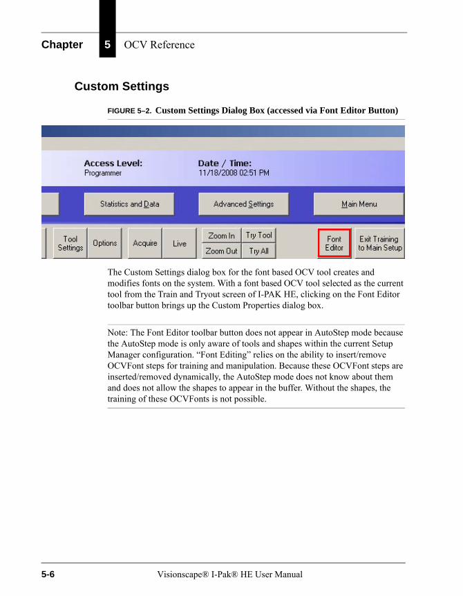
Chapter 5 OCV Reference
Custom Settings
FIGURE 5–2. Custom Settings Dialog Box (accessed via Font Editor Button)
The Custom Settings dialog box for the font based OCV tool creates and modifies fonts on the system. With a font based OCV tool selected as the current tool from the Train and Tryout screen of I-PAK HE, clicking on the Font Editor toolbar button brings up the Custom Properties dialog box.
Note: The Font Editor toolbar button does not appear in AutoStep mode because the AutoStep mode is only aware of tools and shapes within the current Setup Manager configuration. “Font Editing” relies on the ability to insert/remove OCVFont steps for training and manipulation. Because these OCVFont steps are inserted/removed dynamically, the AutoStep mode does not know about them and does not allow the shapes to appear in the buffer. Without the shapes, the training of these OCVFonts is not possible.
5-6 Visionscape® I-Pak® HE User Manual
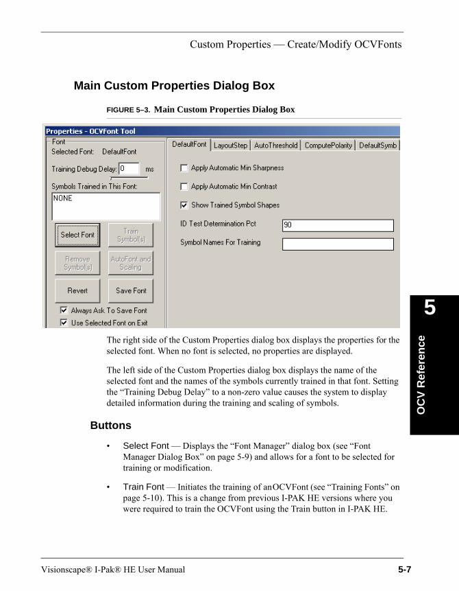
Custom Properties — Create/Modify OCVFonts
OC
V R
efer
ence
5
Main Custom Properties Dialog Box
FIGURE 5–3. Main Custom Properties Dialog Box
The right side of the Custom Properties dialog box displays the properties for the selected font. When no font is selected, no properties are displayed.
The left side of the Custom Properties dialog box displays the name of the selected font and the names of the symbols currently trained in that font. Setting the “Training Debug Delay” to a non-zero value causes the system to display detailed information during the training and scaling of symbols.
Buttons
• Select Font — Displays the “Font Manager” dialog box (see “Font Manager Dialog Box” on page 5-9) and allows for a font to be selected for training or modification.
• Train Font — Initiates the training of an OCVFont (see “Training Fonts” on page 5-10). This is a change from previous I-PAK HE versions where you were required to train the OCVFont using the Train button in I-PAK HE.
Visionscape® I-Pak® HE User Manual 5-7
Chapter 5 OCV Reference
• Remove Symbols — Displays the “Remove Symbols” dialog box (see “Remove Symbol Dialog” on page 5-15) and allows for symbols to be easily removed from the selected font.
• AutoFont and Scaling — Instructs I-PAK HE to determine automatically the best font (from all fonts in the Vscape\Jobs\Fonts folder) for use on the current image (see “Automatic Font Selection & Scaling Dialog” on page 5-15).
• Revert — Reads in the last saved version of the selected font. This allows you to undo all changes since the last save.
• Save Font — Saves any changes made to the selected font.
By default, the “Always Ask To Save Font” checkbox is checked.
• If this box is checked when the Custom Properties dialog box is closed or Select Font is clicked, you are asked if any changes should be saved.
• If this box is not checked, you must remember to save changes or they will be lost when the dialog box is closed, or Select Font is clicked.
By default, the “Use Selected Font on Exit” checkbox is checked.
• If this box is checked when the Custom Properties dialog box is closed, the OCVFont currently active in the Custom Properties dialog box becomes the selected OCVFont for the font based OCV tool that is being trained in I-PAK HE.
• If this box is not checked, no change is made to the selected OCVFont for the tool being trained in I-PAK HE.
5-8 Visionscape® I-Pak® HE User Manual

Custom Properties — Create/Modify OCVFonts
OC
V R
efer
ence
5
Font Manager Dialog Box
FIGURE 5–4. Font Manager Dialog Box
The “Available Fonts” list is the list of all OCVFonts found in the Vscape\Jobs\Fonts folder. OCVFont files have the extension “.ocv”.
Buttons
• Select — When clicked, this button returns you to the Main Custom Properties dialog box with the font selected in the “Available Fonts” list as the selected font.
• New — When clicked, this button prompts you to enter a name for the new font.
FIGURE 5–5. Font Name Dialog Box
You must enter a unique name for the new font. If an OCVFont with the name “DefaultFont.ocv” does not exist in the fonts folder, I-PAK HE will create one and give it the standard default property values. If an OCVFont with the name “DefaultFont.ocv” already exists in the fonts folder, it will not be overwritten. The values of all font properties are copied from “DefaultFont.ocv” to the new font. This allows new fonts to have customized settings based on your requirements.
Visionscape® I-Pak® HE User Manual 5-9
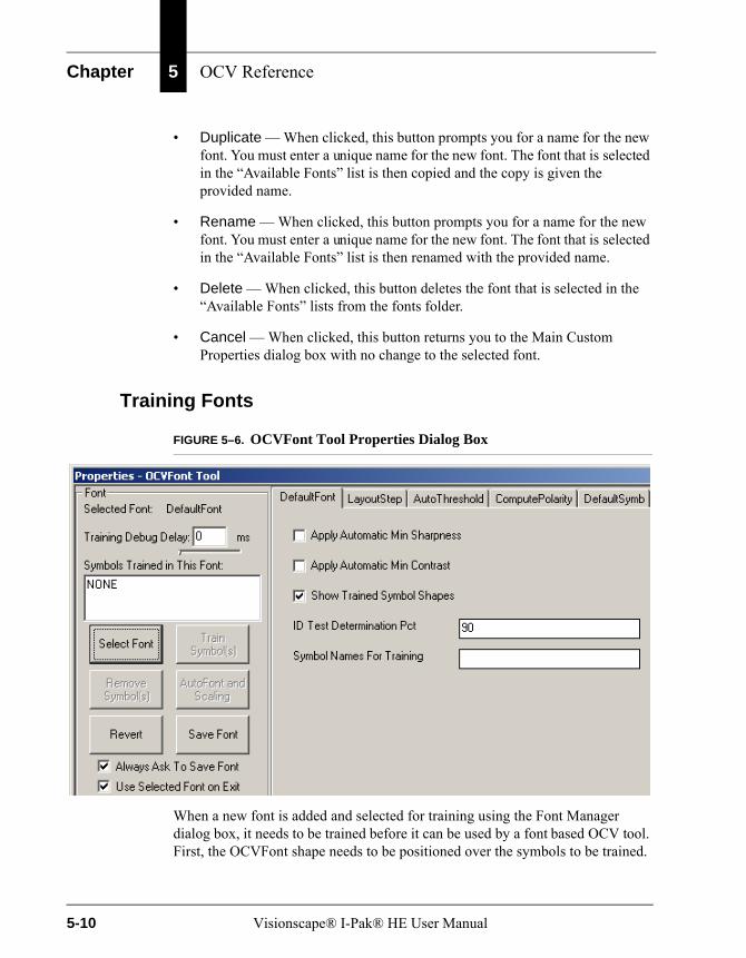
Chapter 5 OCV Reference
• Duplicate — When clicked, this button prompts you for a name for the new font. You must enter a unique name for the new font. The font that is selected in the “Available Fonts” list is then copied and the copy is given the provided name.
• Rename — When clicked, this button prompts you for a name for the new font. You must enter a unique name for the new font. The font that is selected in the “Available Fonts” list is then renamed with the provided name.
• Delete — When clicked, this button deletes the font that is selected in the “Available Fonts” lists from the fonts folder.
• Cancel — When clicked, this button returns you to the Main Custom Properties dialog box with no change to the selected font.
Training Fonts
FIGURE 5–6. OCVFont Tool Properties Dialog Box
When a new font is added and selected for training using the Font Manager dialog box, it needs to be trained before it can be used by a font based OCV tool. First, the OCVFont shape needs to be positioned over the symbols to be trained.
5-10 Visionscape® I-Pak® HE User Manual

Custom Properties — Create/Modify OCVFonts
OC
V R
efer
ence
5
Second, select the LayoutStep tab and enable the Automatic Segmentation property, as shown in Figure 5–4.
FIGURE 5–7. LayoutStep Properties Page
Clicking Train Font on the Custom Properties dialog box initiates the training. You are prompted to name each symbol found in the train ROI.
FIGURE 5–8. Prompt to Enter Unique Name for the Symbol
When training is complete, the right hand side of the Custom Properties dialog box is modified to contain a tab for each symbol that was added to the OCVFont.
Visionscape® I-Pak® HE User Manual 5-11
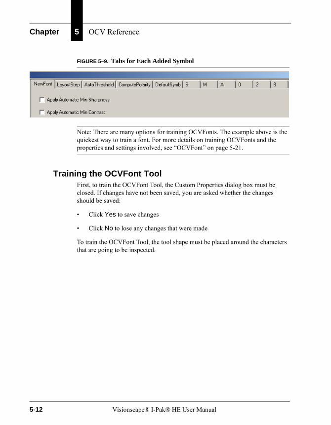
Chapter 5 OCV Reference
FIGURE 5–9. Tabs for Each Added Symbol
Note: There are many options for training OCVFonts. The example above is the quickest way to train a font. For more details on training OCVFonts and the properties and settings involved, see “OCVFont” on page 5-21.
Training the OCVFont ToolFirst, to train the OCVFont Tool, the Custom Properties dialog box must be closed. If changes have not been saved, you are asked whether the changes should be saved:
• Click Yes to save changes
• Click No to lose any changes that were made
To train the OCVFont Tool, the tool shape must be placed around the characters that are going to be inspected.
5-12 Visionscape® I-Pak® HE User Manual
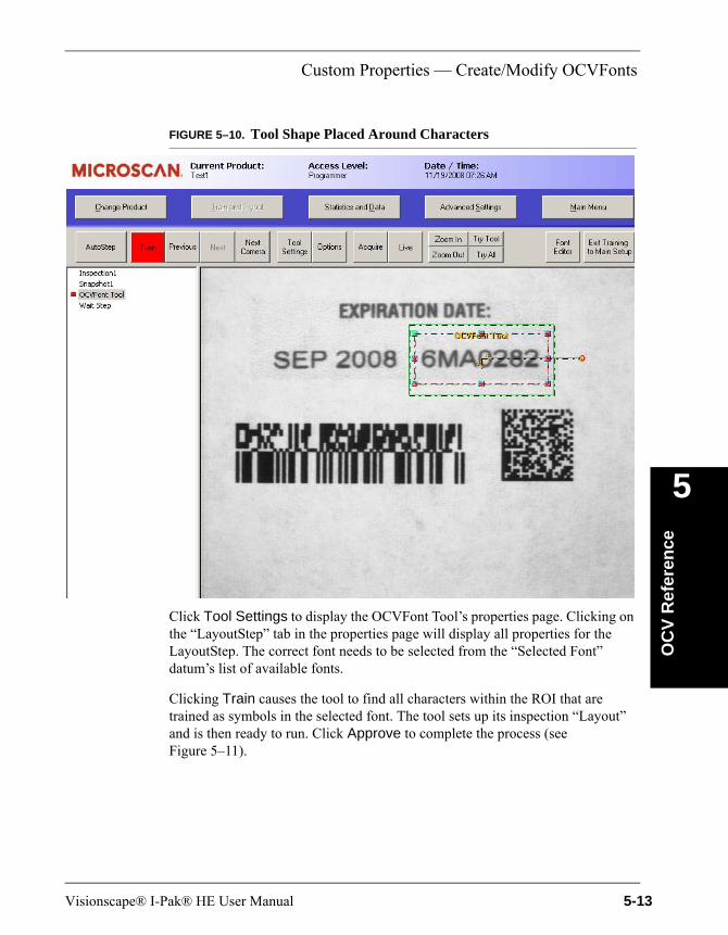
Custom Properties — Create/Modify OCVFonts
OC
V R
efer
ence
5
FIGURE 5–10. Tool Shape Placed Around Characters
Click Tool Settings to display the OCVFont Tool’s properties page. Clicking on the “LayoutStep” tab in the properties page will display all properties for the LayoutStep. The correct font needs to be selected from the “Selected Font” datum’s list of available fonts.
Clicking Train causes the tool to find all characters within the ROI that are trained as symbols in the selected font. The tool sets up its inspection “Layout” and is then ready to run. Click Approve to complete the process (see Figure 5–11).
Visionscape® I-Pak® HE User Manual 5-13
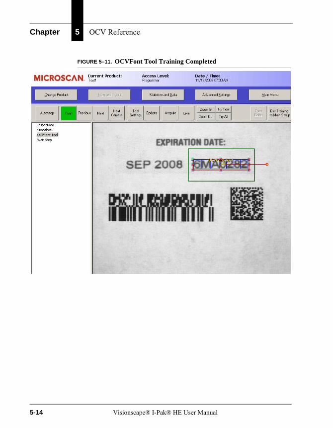
Chapter 5 OCV Reference
FIGURE 5–11. OCVFont Tool Training Completed
5-14 Visionscape® I-Pak® HE User Manual
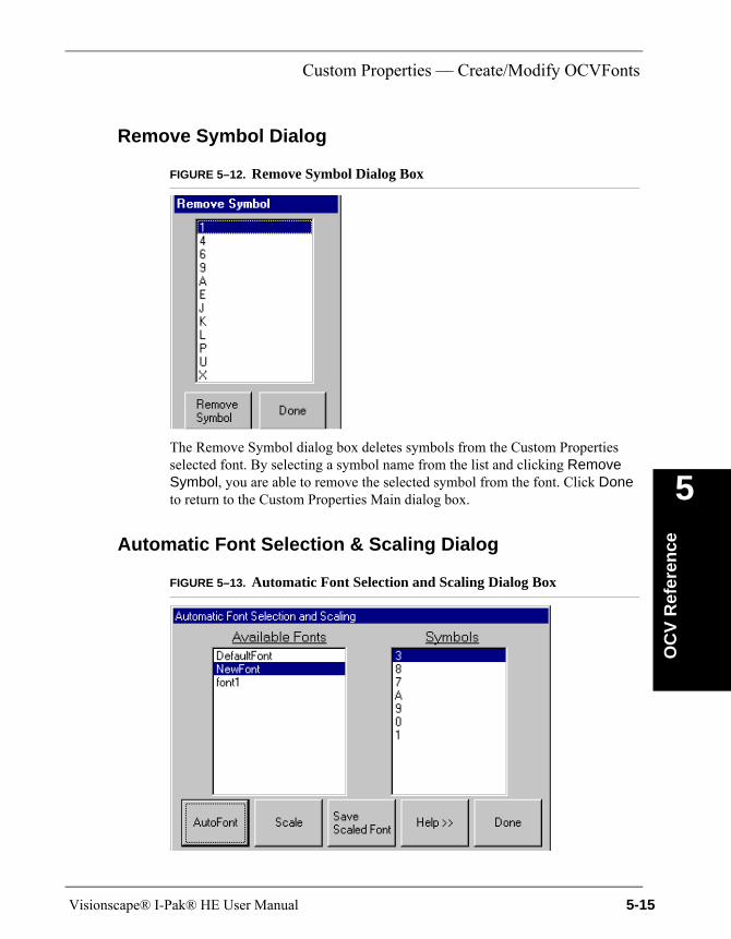
Custom Properties — Create/Modify OCVFonts
OC
V R
efer
ence
5
Remove Symbol Dialog
FIGURE 5–12. Remove Symbol Dialog Box
The Remove Symbol dialog box deletes symbols from the Custom Properties selected font. By selecting a symbol name from the list and clicking Remove Symbol, you are able to remove the selected symbol from the font. Click Done to return to the Custom Properties Main dialog box.
Automatic Font Selection & Scaling Dialog
FIGURE 5–13. Automatic Font Selection and Scaling Dialog Box
Visionscape® I-Pak® HE User Manual 5-15
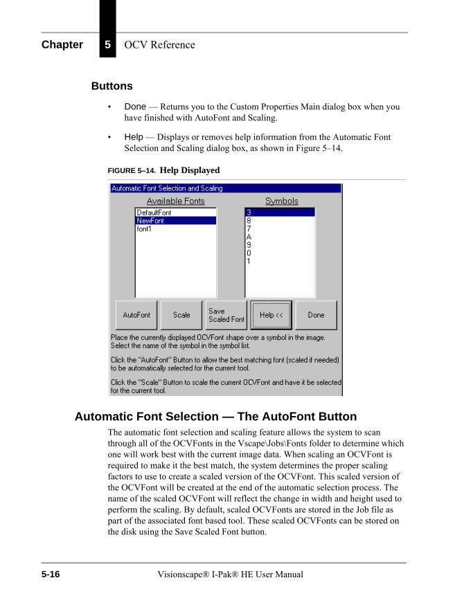
Chapter 5 OCV Reference
Buttons
• Done — Returns you to the Custom Properties Main dialog box when you have finished with AutoFont and Scaling.
• Help — Displays or removes help information from the Automatic Font Selection and Scaling dialog box, as shown in Figure 5–14.
FIGURE 5–14. Help Displayed
Automatic Font Selection — The AutoFont ButtonThe automatic font selection and scaling feature allows the system to scan through all of the OCVFonts in the Vscape\Jobs\Fonts folder to determine which one will work best with the current image data. When scaling an OCVFont is required to make it the best match, the system determines the proper scaling factors to use to create a scaled version of the OCVFont. This scaled version of the OCVFont will be created at the end of the automatic selection process. The name of the scaled OCVFont will reflect the change in width and height used to perform the scaling. By default, scaled OCVFonts are stored in the Job file as part of the associated font based tool. These scaled OCVFonts can be stored on the disk using the Save Scaled Font button.
5-16 Visionscape® I-Pak® HE User Manual
Custom Properties — Create/Modify OCVFonts
OC
V R
efer
ence
5
The Automatic Font Selection and Scaling dialog box has two lists:
• The left hand list is a font list, containing the names of all the OCVFonts in the Vscape\Jobs\Fonts folder.
• The right hand list is a symbol list, containing the names of all the FontSymbols found in the OCVFont that is currently selected in the font list.
Choosing a SymbolSelect a symbol from the symbol list. This symbol will determine the best font. It is important to select a complex, uniquely shaped character. For example, a 5 would be better than a 0 or a 1. The character should appear in the current image and be crisply formed and printed (i.e., no smudges or blurring).
Positioning the OCVFont ShapeThe OCVFont shape of the currently selected font sets up the automatic font selection and scaling process. This shape needs to be positioned and sized around a character in the current image that matches the character selected in the symbol list. It is important that the shape be positioned and sized very tightly over the selected character (do not leave any border). This ensures that the system will not mistake any part of other characters as being part of the selected character.
Note: You may find it easier if the trained symbol shapes are not displayed. Click Done and uncheck Show Trained Symbol Shapes (see Figure 5–9, “Tabs for Each Added Symbol,” on page 5-12).
Visionscape® I-Pak® HE User Manual 5-17
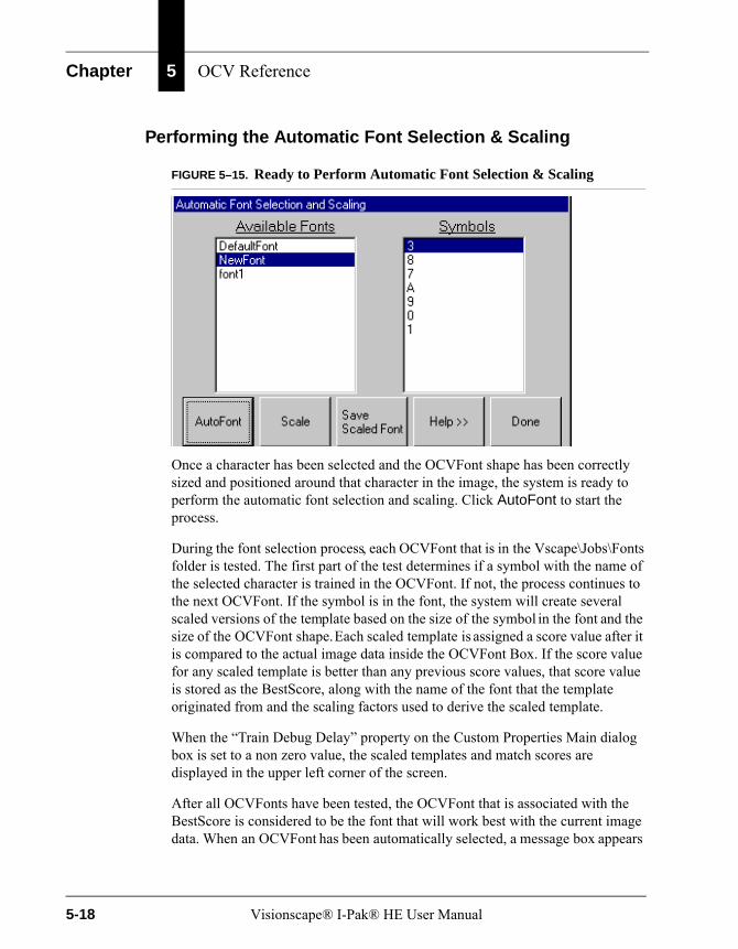
Chapter 5 OCV Reference
Performing the Automatic Font Selection & Scaling
FIGURE 5–15. Ready to Perform Automatic Font Selection & Scaling
Once a character has been selected and the OCVFont shape has been correctly sized and positioned around that character in the image, the system is ready to perform the automatic font selection and scaling. Click AutoFont to start the process.
During the font selection process, each OCVFont that is in the Vscape\Jobs\Fonts folder is tested. The first part of the test determines if a symbol with the name of the selected character is trained in the OCVFont. If not, the process continues to the next OCVFont. If the symbol is in the font, the system will create several scaled versions of the template based on the size of the symbol in the font and the size of the OCVFont shape. Each scaled template is assigned a score value after it is compared to the actual image data inside the OCVFont Box. If the score value for any scaled template is better than any previous score values, that score value is stored as the BestScore, along with the name of the font that the template originated from and the scaling factors used to derive the scaled template.
When the “Train Debug Delay” property on the Custom Properties Main dialog box is set to a non zero value, the scaled templates and match scores are displayed in the upper left corner of the screen.
After all OCVFonts have been tested, the OCVFont that is associated with the BestScore is considered to be the font that will work best with the current image data. When an OCVFont has been automatically selected, a message box appears
5-18 Visionscape® I-Pak® HE User Manual
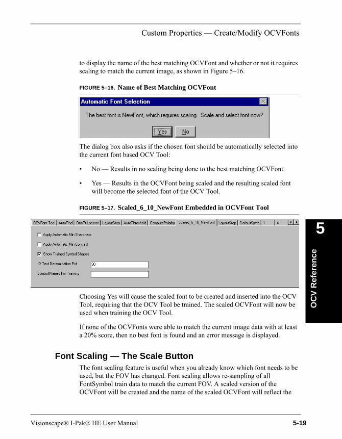
Custom Properties — Create/Modify OCVFonts
OC
V R
efer
ence
5
to display the name of the best matching OCVFont and whether or not it requires scaling to match the current image, as shown in Figure 5–16.
FIGURE 5–16. Name of Best Matching OCVFont
The dialog box also asks if the chosen font should be automatically selected into the current font based OCV Tool:
• No — Results in no scaling being done to the best matching OCVFont.
• Yes — Results in the OCVFont being scaled and the resulting scaled font will become the selected font of the OCV Tool.
FIGURE 5–17. Scaled_6_10_NewFont Embedded in OCVFont Tool
Choosing Yes will cause the scaled font to be created and inserted into the OCV Tool, requiring that the OCV Tool be trained. The scaled OCVFont will now be used when training the OCV Tool.
If none of the OCVFonts were able to match the current image data with at least a 20% score, then no best font is found and an error message is displayed.
Font Scaling — The Scale ButtonThe font scaling feature is useful when you already know which font needs to be used, but the FOV has changed. Font scaling allows re-sampling of all FontSymbol train data to match the current FOV. A scaled version of the OCVFont will be created and the name of the scaled OCVFont will reflect the
Visionscape® I-Pak® HE User Manual 5-19

Chapter 5 OCV Reference
change in width and height used to perform the scaling. By default, scaled OCVFonts are stored in the Job file as part of the associated font based tool. These scaled OCVFonts can be stored on the disk using the Save Scaled Font button.
Choosing a SymbolChoose the OCVFont that needs scaling from the font list. Select a symbol from the symbol list. This symbol will determine the changes in width and height that are needed to perform the font scaling. The character should appear in the current image and be crisply formed and printed (i.e., no smudges or blurring).
Positioning the OCVFont ShapeThe OCVFont shape of the currently selected font sets up the font scaling process. This shape needs to be positioned and sized around a character in the current image that matches the character selected in the symbol list. It is important that the shape be positioned and sized very tightly over the selected character (do not leave any border). This ensures that the system will correctly calculate the changes in width and height.
Note: You may find it easier if the trained symbol shapes are not displayed. Click Done and uncheck Show Trained Symbol Shapes (see Figure 5–9, “Tabs for Each Added Symbol,” on page 5-12.
Performing the Font ScalingOnce a character has been selected and the OCVFont shape has been correctly sized and positioned around that character, the system is ready to perform the font scaling. Click Scale to start the process. The system compares the trained width of the selected FontSymbol with the width of the OCVFont box and calculates the required change in width to scale the FontSymbol in X. Then, the system compares the trained height of the selected FontSymbol with the height of the OCVFont box and calculates the required change in height to scale the FontSymbol in Y. Then, a new OCVFont is created and given the name of the source OCVFont with the addition of the change in width and change in height values. For example, OldFont_2_-5 indicates that the OCVFont named “OldFont” was scaled by increasing the width of the symbols by 2 and decreasing the height of the symbols by 5. Each symbol that is in the source OCVFont is then scaled and added to the new OCVFont.
5-20 Visionscape® I-Pak® HE User Manual
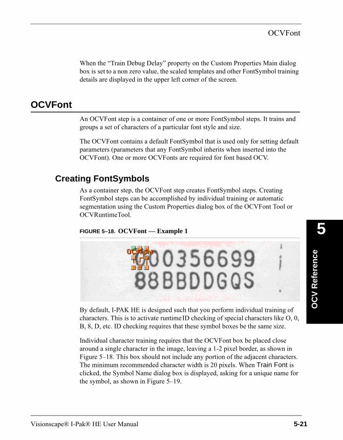
OCVFont
OC
V R
efer
ence
5
When the “Train Debug Delay” property on the Custom Properties Main dialog box is set to a non zero value, the scaled templates and other FontSymbol training details are displayed in the upper left corner of the screen.
OCVFontAn OCVFont step is a container of one or more FontSymbol steps. It trains and groups a set of characters of a particular font style and size.
The OCVFont contains a default FontSymbol that is used only for setting default parameters (parameters that any FontSymbol inherits when inserted into the OCVFont). One or more OCVFonts are required for font based OCV.
Creating FontSymbolsAs a container step, the OCVFont step creates FontSymbol steps. Creating FontSymbol steps can be accomplished by individual training or automatic segmentation using the Custom Properties dialog box of the OCVFont Tool or OCVRuntimeTool.
FIGURE 5–18. OCVFont — Example 1
By default, I-PAK HE is designed such that you perform individual training of characters. This is to activate runtime ID checking of special characters like O, 0, B, 8, D, etc. ID checking requires that these symbol boxes be the same size.
Individual character training requires that the OCVFont box be placed close around a single character in the image, leaving a 1-2 pixel border, as shown in Figure 5–18. This box should not include any portion of the adjacent characters. The minimum recommended character width is 20 pixels. When Train Font is clicked, the Symbol Name dialog box is displayed, asking for a unique name for the symbol, as shown in Figure 5–19.
Visionscape® I-Pak® HE User Manual 5-21
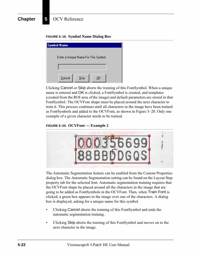
Chapter 5 OCV Reference
FIGURE 5–19. Symbol Name Dialog Box
Clicking Cancel or Skip aborts the training of this FontSymbol. When a unique name is entered and OK is clicked, a FontSymbol is created, and templates (created from the ROI area of the image) and default parameters are stored in that FontSymbol. The OCVFont shape must be placed around the next character to train it. This process continues until all characters in the image have been trained as FontSymbols and added to the OCVFont, as shown in Figure 5–20. Only one example of a given character needs to be trained.
FIGURE 5–20. OCVFont — Example 2
The Automatic Segmentation feature can be enabled from the Custom Properties dialog box. The Automatic Segmentation setting can be found on the Layout Step property tab for the selected font. Automatic segmentation training requires that the OCVFont shape be placed around all the characters in the image that are going to be added as FontSymbols in the OCVFont. Then, when Train Font is clicked, a green box appears in the image over one of the characters. A dialog box is displayed, asking for a unique name for this symbol.
• Clicking Cancel aborts the training of this FontSymbol and ends the automatic segmentation training.
• Clicking Skip aborts the training of this FontSymbol and moves on to the next character in the image.
5-22 Visionscape® I-Pak® HE User Manual

OCVFont
OC
V R
efer
ence
5
Only one example of a character needs to be trained.
When a unique name is entered and OK is clicked, a FontSymbol is created, and templates (created from the ROI area of the image) and default parameters are stored in that FontSymbol. The green box changes to a red box and a new green box appears over the next character in the image. This process continues until all characters in the image have been trained as FontSymbols and added to the OCVFont or the process is canceled.
OCVFont TabWhen an OCVFont is selected in the Custom Properties dialog box, the OCVFont tab displays the current settings for that OCVFont.
FIGURE 5–21. OCVFont Properties Page
• Apply Automatic Min Sharpness — When enabled, as FontSymbols are trained and added to this OCVFont, a minimum tolerance for sharpness is calculated for the FontSymbol. This value is 65% of the sharpness value calculated using the trained grayscale template of the FontSymbol.
Default: Disabled
• Apply Automatic Min Contrast — When enabled, as FontSymbols are trained and added to this OCVFont, a minimum tolerance for contrast is calculated for the FontSymbol. This value is 50% of the contrast value calculated using the trained grayscale template of the FontSymbol.
Default: Disabled
Visionscape® I-Pak® HE User Manual 5-23

Chapter 5 OCV Reference
• Show Trained Symbol Shapes — When enabled, the shapes of all FontSymbols that are part of this OCVFont are displayed whenever the shape for this OCVFont is selected in the buffer view.
Default: Enabled
• ID Test Determination Pct — When a FontSymbol is trained as part of an OCVFont, it is compared against all of the FontSymbols already in the OCVFont. When FontSymbols are found to be similar, special tests are set up to check for the presence of the correct symbol at runtime.
Default: 90%Range: 10% to 100%
ID Test Determination Pct adjusts the level at which symbols are similar enough to require special runtime tests. Smaller percentages cause more symbols to be flagged as similar, while larger percentages cause less symbols to be flagged as similar.
Examples — When two symbols are found to be 75% similar, and the value of this property is 85%, no special tests are set up for runtime ID checking; if two symbols are found to be 90% similar, and the value of the property is 85%, a special test is set up for runtime ID checking.
LayoutStep TabThe LayoutStep tab of the OCVFont is used for automatic segmentation of the image, when enabled. When an OCVFont is selected in the Custom Properties dialog box, the LayoutStep tab displays the current settings for that OCVFont’s LayoutStep.
FIGURE 5–22. LayoutStep Properties Page
• Automatic Segmentation — When enabled, the training of the OCVFont causes the image to be segmented using blob analysis. A dialog box is
5-24 Visionscape® I-Pak® HE User Manual

OCVFont
OC
V R
efer
ence
5
displayed, asking for a unique name to give the FontSymbol before training the FontSymbol for each position found.
Default: Disabled
• Min Symbol Size <in pixels> — Adjusts the minimum size that a blob must be in order to be considered a symbol.
Default: 10 pixelsRange: 5 to 256 pixels
• Num Border Spaces to Add — Determines how many pixels to allow between actual character pixels and the edge of the box that defines the FontSymbol.
Default: 1 pixelRange: 0 to 19 pixels
AutoThreshold TabThe AutoThreshold tab of the OCVFont is part of the LayoutStep that is used for automatic segmentation of the image, when enabled, as shown in Figure 5–23.
FIGURE 5–23. AutoThreshold Properties Page
• Auto Thresholding Enabled — Enables and disables automatic thresholding.
When enabled, a threshold is calculated using the ROI of the step. This calculation uses edge detection to determine foreground and background information. The calculated threshold is displayed in the Threshold property.
Visionscape® I-Pak® HE User Manual 5-25
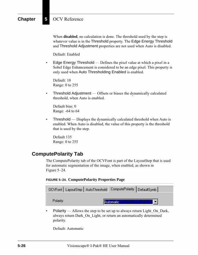
Chapter 5 OCV Reference
When disabled, no calculation is done. The threshold used by the step is whatever value is in the Threshold property. The Edge Energy Threshold and Threshold Adjustment properties are not used when Auto is disabled.
Default: Enabled
• Edge Energy Threshold — Defines the pixel value at which a pixel in a Sobel Edge Enhancement is considered to be an edge pixel. This property is only used when Auto Thresholding Enabled is enabled.
Default: 10Range: 0 to 255
• Threshold Adjustment — Offsets or biases the dynamically calculated threshold, when Auto is enabled.
Default bias: 0Range: -64 to 64
• Threshold — Displays the dynamically calculated threshold when Auto is enabled. When Auto is disabled, the value of this property is the threshold that is used by the step.
Default 135Range: 0 to 255
ComputePolarity TabThe ComputePolarity tab of the OCVFont is part of the LayoutStep that is used for automatic segmentation of the image, when enabled, as shown in Figure 5–24.
FIGURE 5–24. ComputePolarity Properties Page
• Polarity — Allows the step to be set up to always return Light_On_Dark, always return Dark_On_Light, or return an automatically determined polarity.
Default: Automatic
5-26 Visionscape® I-Pak® HE User Manual
FontSymbol
OC
V R
efer
ence
5
DefaultSymb TabThe DefaultSymb tab of the OCVFont sets default parameters that any FontSymbol trained and added to the OCVFont receives.
FontSymbolA FontSymbol is a collection of template images, settings, and tolerances that inspect a character or logo at runtime. FontSymbols are created during the training of an OCVFont. They are used by the OCVFont Tool and OCVRuntimeTool steps to learn the layout at train time and inspect the layout at runtime.
FontSymbols are trained when they are added to an OCVFont.
Visionscape® I-Pak® HE User Manual 5-27
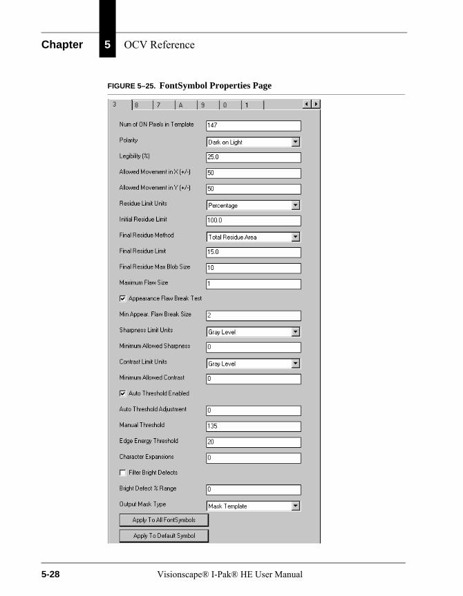
Chapter 5 OCV Reference
FIGURE 5–25. FontSymbol Properties Page
5-28 Visionscape® I-Pak® HE User Manual
FontSymbol
OC
V R
efer
ence
5
• Num of ON Pixels in Template — Displays the number of foreground pixels in the trained binary template.
• Polarity — Allows the step to always train with polarity Light_On_Dark, always train with polarity Dark_On_Light, or train using an automatically calculated polarity.
Default: Automatic
• Legibility (%) — Passes/fails the symbol based on this minimum correlation percentage. The symbol fails inspection when the correlation percentage is less than this value.
Default: 25% (typical for pharmaceutical applications)Range: 0% to 100%
• Allowed Movement in X (+/-) — Sets the maximum number of pixels that a symbol can move in the X-axis (relative to other symbols) from its trained position.
Default: 50 pixels (any movement is allowed)Range: 0 to 50 pixels. The maximum of 50 pixels comes from the parent OCVTool setting Individual Symbol Search X, which limits the search range in X to a maximum of 50 pixels in either direction.
• Allowed Movement in Y (+/-) — Set the maximum number of pixels that a symbol can move in the Y-axis (relative to other symbols) from its trained position.
Default: 50 pixels (any movement is allowed)Range: 0 to 50 pixels. The maximum of 50 pixels comes from the parent OCVTool setting Individual Symbol Search Y, which limits the search range in Y to a maximum of 50 pixels in either direction.
• Residue Limit Units — Inputs the residue limits in either a maximum pixel count value or a percentage value (percentage value is based on the number of On pixels in the trained template). When the value of this property changes, the values of Initial Residue Limit and Final Residue Limit are changed to match the selected units.
Default: Percentage
Visionscape® I-Pak® HE User Manual 5-29
Chapter 5 OCV Reference
• Initial Residue Limit — Provides a quick check of the character quality and correctness. The initial residue calculation is done before any image processing is performed on the residue image.
When the system looks at the symbol being inspected, it determines the residue of the symbol, which is a count of those pixels that differ between the trained template and the current image. Based on the value of this property, the system determines if the residue is within tolerances. If it is not within tolerances, the symbol fails. Otherwise, the system continues on with the rest of the inspection procedure.
When Residue Limit Units is set to Percentage:
Default: 100.0%Range: 0.0% to 100.0%
The value of this property is the smallest percentage of residue pixels (relative to the trained On pixel count) in the inspected image that will make the symbol fail the inspection.
When Residue Limit Units is set to Pixels:
Default: symbol sizeRange: 0 to symbol size
The value of this property is the smallest count of residue pixels in the inspected image that will make the symbol fail the inspection.
This property is good for catching smudges that are poor aesthetically, but would pass after all inspection operations are performed on it. A property value of 100% or symbol size means initial residue is ignored.
• Final Residue Method — Selects between three algorithms for final residue analysis.
– Total Residue Area — This is the default. This choice counts all On pixels in the residue image and use the value in Final Residue Limit (pixel or percent) as the tolerance.
– Max Residue Blob — Only counts the pixels in the largest blob of the residue image and use the value in Final Residue Max Blob Size as the tolerance.
– Both — Performs both methods.
5-30 Visionscape® I-Pak® HE User Manual
FontSymbol
OC
V R
efer
ence
5
• Final Residue Limit — Sets the amount of objectionable residue that is to be deemed passable when Final Residue Method is set to Total Residue Area or Both. Final residue calculation is done after the image processing on the residue image that is associated with Maximum Flaw Size.
An assignment of 0% (residue pixel count = 0) means that no residue is passable. An assignment of 100% (residue pixel count = symbol size) means that objectionable residue as large as the area of the prototype itself is passable.
When Residue Limit Units is set to Percentage:
Default: 15.0% (meaning a 15% variation is acceptable)Range: 0.0% to 100.0%
The value of this property is the smallest percentage of residue pixels (relative to the trained On pixel count) in the inspected image that makes the symbol fail the inspection.
When Residue Limit Units is set to Pixels:
Default: 15% of the symbol sizeRange: 0 to symbol size
The value of this property is the smallest count of residue pixels in the inspected image that makes the symbol fail the inspection.
Note: Determining the proper value for Final Residue Limit is a subjective decision; the higher the quality of the character/symbol desired, the lower the Final Residue Limit should be.
• Final Residue Max Blob Size — Used when Final Residue Method is set to Max Residue Blob or Both. A blob analysis is performed on the residue image and the largest blob is found. If this blob has an area that is greater than the value of this property, the symbol fails the inspection.
Default: 10Range: 1 to 512
• Maximum Flaw Size — Represents the maximum width in pixels that a discrepancy is allowed to be before it is considered objectionable. The larger the number assigned, the larger a discrepancy is allowed before causing the symbol inspection to fail.
Visionscape® I-Pak® HE User Manual 5-31
Chapter 5 OCV Reference
Default: 1 pixelsRange: 0 to 20 pixels
• Appearance Flaw Break Test — Determines whether the FontSymbol is to inspect for character breaks in the symbol. When enabled, the inspection fails if a break is found in the symbol. When disabled, the inspection ignores breaks in the symbol.
Default: Enabled
• Min Appear. Flaw Break Size — Is the smallest size break that causes a character break failure.
Default: 2 pixelsRange: 1 to 10 pixels
• Sharpness Limit Units — Sets the units for the “Minimum Allowed Sharpness” property:
– When set to Gray Level, the value of the “Minimum Allowed Sharpness” property is used as an absolute minimum value that the calculated sharpness value must be in order for the inspection to pass.
– When set to Percentage, the value of the “Minimum Allowed Sharpness” is used to calculate a percentage of the trained sharpness value, which is then used as an absolute minimum value that the calculated sharpness value must be in order for the inspection to pass.
– When switched from Gray Level to Percentage, the “Minimum Allowed Sharpness” property is updated to be the percentage value that corresponds to the gray level value that it previously held.
– When switched from Percentage to Gray Level, the “Minimum Allowed Sharpness” property is updated to be the gray level value that corresponds to the percentage value that it previously held.
Default: Gray Level
• Minimum Allowed Sharpness — This value determines how crisp a symbol must be to pass inspection. It is measured by average edge strength over the entire symbol. Typical edge strengths are from 20 to 80 sharpness units.
Default: 0Range: 0 to 256 “Gray Level” or 0 to 100 “Percentage”
5-32 Visionscape® I-Pak® HE User Manual

FontSymbol
OC
V R
efer
ence
5
• Contrast Limit Units — Sets the units for the “Minimum Allowed Contrast” property:
– When set to Gray Level, the value of the “Minimum Allowed Contrast” property is used as an absolute minimum value that the calculated contrast value must be in order for the inspection to pass.
– When set to Percentage, the value of the “Minimum Allowed Contrast” is used to calculate a percentage of the trained contrast value, which is then used as an absolute minimum value that the calculated contrast value must be in order for the inspection to pass.
– When switched from Gray Level to Percentage, the “Minimum Allowed Contrast” property is updated to be the percentage value that corresponds to the gray level value that it previously held.
– When switched from Percentage to Gray Level, the “Minimum Allowed Contrast” property is updated to be the gray level value that corresponds to the percentage value that it previously held.
Default: Gray Level
• Minimum Allowed Contrast — The Contrast is the measurement that defines the grayscale foreground to background relationship of the symbol data. To calculate the contrast value, the average gray level value of the background pixels is subtracted from the average gray level of the foreground pixels. Whenever this property has a value of 0, no contrast checks are performed.
Default: 0Range: 0 to 256 “Gray Level” or 0 to 100 “Percentage”
• Auto Threshold Enabled — Enables or disables the automatic calculation of a threshold for binarizing the image at both train and run time. When enabled, the calculated threshold is displayed in the Manual Threshold property. When disabled, no calculation is done. The threshold used for binarizing is whatever value is in the Manual Threshold property. The Edge Energy Threshold and Threshold Adjustment properties are not used when disabled.
Default: Enabled
• Auto Threshold Adjustment — Offsets or biases the dynamically calculated threshold when Auto Threshold Enabled is enabled.
Visionscape® I-Pak® HE User Manual 5-33
Chapter 5 OCV Reference
Default: 0Range: -64 to 64
• Manual Threshold — Displays the dynamically calculated threshold when Auto Threshold Enabled is enabled. When Auto Threshold Enabled is disabled, the value of this property is the threshold that is used for binarizing the image.
Default: 135Range: 0 to 255
• Edge Energy Threshold — Defines the pixel value at which a pixel in a Sobel Edge Enhancement is considered to be an edge pixel. This is only used when Auto Threshold Enabled is enabled.
Default: 10Range: 0 to 255
• Character Expansions — Useful when dealing with print from a dot matrix printer or any print that is broken up in segments. The more sparse the print, the higher the value of this property should be. This allows for the broken print to become solid by expanding the segments until they come together. Dilations expand each segment. Then, erosions decrease the size of the character in every direction except the direction in which the segments have connected. Dilations and erosions work together to make the segments solid without making the character fatter.
Default: 0Range: 0 to 9
• Filter Bright Defects — When enabled, runtime inspection of the symbol includes a pre-processing step for filtering out any bright defects in the image.
Default: Disabled
• Bright Defect % Range — The value is a percentage that determines the threshold at which the bright defect filter processes. The threshold is calculated by taking this percentage of the range between the binarizing threshold and 255. This means that the binary threshold would be used when Filter Bright Defects is enabled.
Default: 0Range: 0 to 100
5-34 Visionscape® I-Pak® HE User Manual

AutoFind
OC
V R
efer
ence
5
• Output Mask Type — Used in conjunction with the DynamicMask step. The selections are:
– None — Adds nothing to the mask.
– Mask Template (default) — Only the foreground area of the symbol is added to the mask.
– Mask ROI — The entire area within the symbol's ROI is added to the mask.
• Apply to All FontSymbols — Sets the properties of all symbols in the OCVFont to the values currently shown on the page.
• Apply to Default Symbol — Sets the properties of the default symbol of the OCVFont to the values currently shown on the page.
The factory default settings work well for most applications. When adjustments to Pass/Fail limits are required, modify the following settings first:
– Final Residue Limit
– Maximum Flaw Size
Increasing Final Residue to 20% allows more variations to be accepted. Changing the Final Residue % has a gradual effect on Pass/Fail. Using a high Final Residue %, such as 50%, on small characters such as - can reduce false rejects.
Increasing the Maximum Flaw Size has a pronounced effect on Pass/Fail. Increasing Maximum Flaw Size allows more character variations to be acceptable. For many applications, this value should not be set greater than 2.
AutoFindAny of the OCV Tools can optionally use an AutoFind. This step determines the location of the layout at runtime. You can set up an AutoFind to use 1-Pin (no rotation) or 2-Pins (rotation). Set up the Pins by selecting which layout positions to use on the OCV Tool properties page.
Visionscape® I-Pak® HE User Manual 5-35
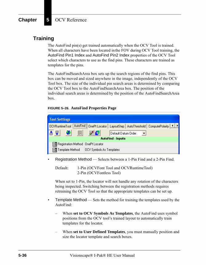
Chapter 5 OCV Reference
TrainingThe AutoFind pin(s) get trained automatically when the OCV Tool is trained. When all characters have been located in the FOV during OCV Tool training, the AutoFind Pin1 Index and AutoFind Pin2 Index properties of the OCV Tool select which characters to use as the find pins. These characters are trained as templates for the pins.
The AutoFindSearchArea box sets up the search regions of the find pins. This box can be moved and sized anywhere in the image, independently of the OCV Tool box. The size of the individual pin search areas is determined by comparing the OCV Tool box to the AutoFindSearchArea box. The position of the individual search areas is determined by the position of the AutoFindSearchArea box.
FIGURE 5–26. AutoFind Properties Page
• Registration Method — Selects between a 1-Pin Find and a 2-Pin Find.
Default: 1-Pin (OCVFont Tool and OCVRuntimeTool)2-Pin (OCVFontless Tool)
When set to 1-Pin, the locator will not handle any rotation of the characters being inspected. Switching between the registration methods requires retraining the OCV Tool so that the appropriate templates can be set up.
• Template Method — Sets the method for training the templates used by the AutoFind:
– When set to OCV Symbols As Templates, the AutoFind uses symbol positions from the OCV tool’s trained layout to automatically train templates for the locator.
– When set to User Defined Templates, you must manually position and size the locator template and search boxes.
5-36 Visionscape® I-Pak® HE User Manual
OCVFont Tool
OC
V R
efer
ence
5
Default: OCV Symbols As Templates
OCVFont ToolAn OCVFont Tool uses an OCVFont to learn the layout, and determine which characters from the OCVFont are in which locations in the ROI. Once the layout is learned, the OCVFont Tool expects to find these symbols at the same locations in the ROI during inspection. It uses the data from the FontSymbols in the OCVFont to verify the quality and correctness of the characters being inspected.
TrainingTraining of the OCVFont Tool involves placing and sizing the OCVFont Tool box around the area containing the symbols to be inspected. When Train is clicked, the ROI is scanned for symbol candidates. Symbol candidates are determined by searching for each symbol that is in the selected OCVFont, chosen through the LayoutStep.
Then, the OCVFont Tool box is reset based on the bounding rectangle of all symbols found and the values of the search extra properties. The AutoFind is trained automatically whenever the OCVFont Tool is trained. When the AutoFind Search Area Box is moved and/or sized, it is retrained automatically, without requiring retraining of the OCVFont Tool.
InspectionIf AutoFind is enabled, the pins are located and the OCVFont Tool box is re-positioned based on the pin locations. Each symbol found during training is expected to be at the same location within the OCVFont Tool box at runtime. For each symbol position, there are several ways that an inspection can fail:
• The symbol cannot be located.
• The symbol can fail because the sharpness value is out of tolerance.
• The symbol can fail because the contrast value is out of tolerance.
• The symbol can fail because a break larger than the user-specified size appears in the character.
• The symbol failed an ID Test. It could not be determined that the correct symbol was present.
Visionscape® I-Pak® HE User Manual 5-37
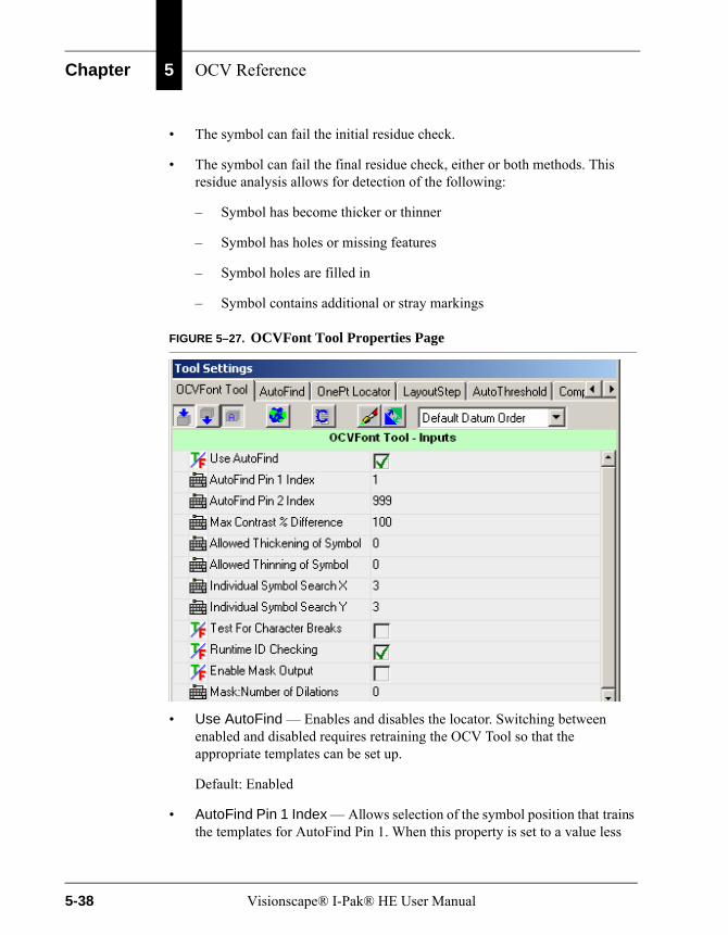
Chapter 5 OCV Reference
• The symbol can fail the initial residue check.
• The symbol can fail the final residue check, either or both methods. This residue analysis allows for detection of the following:
– Symbol has become thicker or thinner
– Symbol has holes or missing features
– Symbol holes are filled in
– Symbol contains additional or stray markings
FIGURE 5–27. OCVFont Tool Properties Page
• Use AutoFind — Enables and disables the locator. Switching between enabled and disabled requires retraining the OCV Tool so that the appropriate templates can be set up.
Default: Enabled
• AutoFind Pin 1 Index — Allows selection of the symbol position that trains the templates for AutoFind Pin 1. When this property is set to a value less
5-38 Visionscape® I-Pak® HE User Manual

OCVFont Tool
OC
V R
efer
ence
5
than or equal to 1, the first symbol position is used. When this property is set to a value greater than or equal to the number of trained symbols, the last symbol position is used.
Default: 1, meaning use the first symbolRange: 1 to n, where n is greater than or equal to the number of
trained symbols
• AutoFind Pin 2 Index — Allows selection of the symbol position that trains the templates for AutoFind Pin 2 (when the AutoFind is set up as a 2PinFind). When this property is set to a value less than or equal to 1, the first symbol position is used. When this property is set to a value greater than or equal to the number of trained symbols, the last symbol position is used.
Default: 999 (use the last symbol)Range: 1 to n, where n is greater than or equal to the number of
trained symbols
• Max Contrast % Difference — Sets the maximum percentage difference between the calculated contrast values for symbols being inspected by the tool. When set to 100%, any contrast difference is acceptable. If no contrast calculations are performed for the inspected symbols, the calculated percent difference is 0. Otherwise, the smallest contrast from the inspected symbols is divided by the largest contrast from the inspected symbols. This value is then subtracted from 1 to get the percentage difference. If the calculated the difference is larger than the value of “Max Contrast % Difference”, the inspection fails.
Default: 100%Range: 0 to 100%
• Allowed Thickening of Symbol — Determines the number of pixels that a symbol is allowed to grow along its perimeter. Residue will be ignored if it is found in the region between the edge of the symbol and the set number of pixels away from the edge, in the direction away from the center of the symbol.
Default: 0 pixelsRange: 0 to 10 pixels
• Allowed Thinning of Symbol — Determines the number of pixels that a symbol is allowed to shrink along its perimeter. Residue will be ignored if it is found in the region between the edge of the symbol and the set number of pixels away from the edge, in the direction toward the center of the symbol.
Visionscape® I-Pak® HE User Manual 5-39
Chapter 5 OCV Reference
Default: 0 pixelsRange: 0 to 10 pixels
• Individual Symbol Search X — Determines the width of the search area for individual symbols. This number is doubled and added to the symbol width to get the search width.
Default: 3 pixelsRange: 0 to 50 pixels
• Individual Symbol Search Y — Determines the height of the search area for individual symbols. This number is doubled and added to the symbol height to get the search height.
Default: 3 pixelsRange: 0 to 50 pixels
• Test For Character Breaks — Enables and disables the checks for character break appearance flaws.
Default: Disabled
• Runtime ID Checking — Enables and disables the tests that determine if the correct symbol is present at runtime.
During training of an OCVFont, the FontSymbols that are added are checked against each other to determine how similar they are. When FontSymbols are found to be very similar, tests for determining the presence of the correct symbol are set up and stored with the FontSymbols. These tests are only performed at runtime when Runtime ID Checking is enabled.
Default: Enabled
• Enable Mask Output — Enables and disables the creation and output of a mask at runtime. This property is used in conjunction with the DynamMask Tool to allow the printed characters to be excluded (masked out) from other image processing. Enabling this property increases inspection time.
Default: Disabled
• Mask: Number of Dilations — Sets the number of expansions that are performed on the output mask. This property is used in conjunction with the DynamMask Tool to allow the printed characters to be excluded (masked out) from other image processing.
5-40 Visionscape® I-Pak® HE User Manual
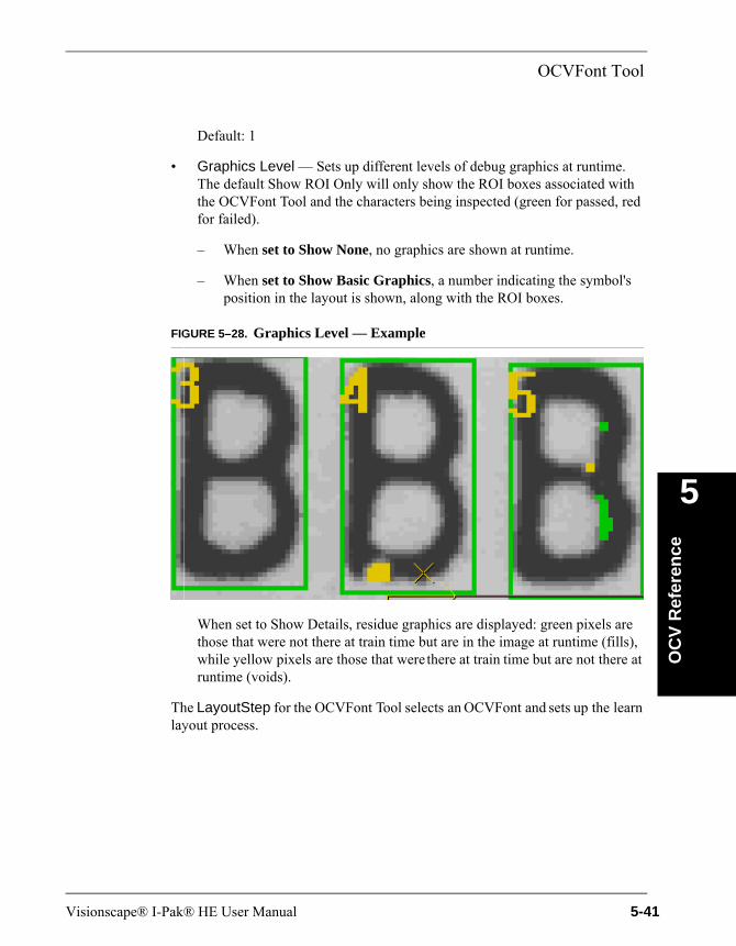
OCVFont Tool
OC
V R
efer
ence
5
Default: 1
• Graphics Level — Sets up different levels of debug graphics at runtime. The default Show ROI Only will only show the ROI boxes associated with the OCVFont Tool and the characters being inspected (green for passed, red for failed).
– When set to Show None, no graphics are shown at runtime.
– When set to Show Basic Graphics, a number indicating the symbol's position in the layout is shown, along with the ROI boxes.
FIGURE 5–28. Graphics Level — Example
When set to Show Details, residue graphics are displayed: green pixels are those that were not there at train time but are in the image at runtime (fills), while yellow pixels are those that were there at train time but are not there at runtime (voids).
The LayoutStep for the OCVFont Tool selects an OCVFont and sets up the learn layout process.
Visionscape® I-Pak® HE User Manual 5-41

Chapter 5 OCV Reference
FIGURE 5–29. LayoutStep Properties Page
• Selected Font — Allows selection of an OCVFont to use for training and inspections. This property is a drop-down list containing the names of all OCVFonts that are in the Vscape\Jobs\Fonts folder.
• Allowed Overlap During Read — Used during the learn layout process. The value of this property specifies the amount of symbol candidate ROI overlap that is allowed. When symbol candidates overlap more than the allowed value, tests are performed to determine the best candidate at the overlap position. The other candidate will not become part of the layout. This overlap measurement is in pixels.
Default: 5 pixelsRange: 0 to 15 pixels
• Min Read Match % — Is a correlation percentage used as a minimum requirement for a symbol to be considered a candidate during the learn layout process.
Default: 65%Range: 0% to 100%
Note: When characters are not being read during Learn Layout, decrease this property to 60%. Avoid settings below 55%.
• Automatic Threshold Adjustment — Enables and disables the automatic threshold adjustment feature. When enabled, the best match location during the learn layout process calculates an adjustment to the threshold used to
5-42 Visionscape® I-Pak® HE User Manual
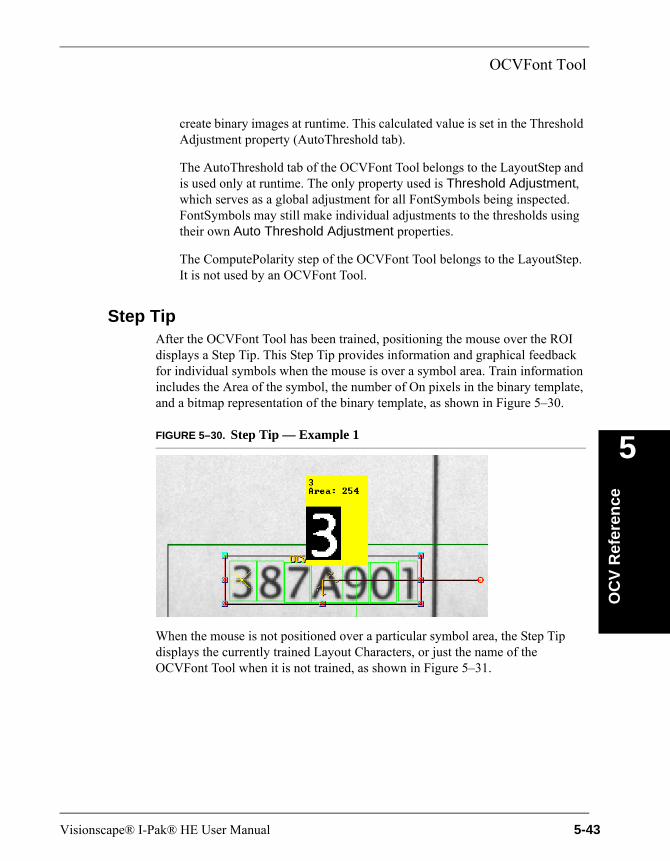
OCVFont Tool
OC
V R
efer
ence
5
create binary images at runtime. This calculated value is set in the Threshold Adjustment property (AutoThreshold tab).
The AutoThreshold tab of the OCVFont Tool belongs to the LayoutStep and is used only at runtime. The only property used is Threshold Adjustment, which serves as a global adjustment for all FontSymbols being inspected. FontSymbols may still make individual adjustments to the thresholds using their own Auto Threshold Adjustment properties.
The ComputePolarity step of the OCVFont Tool belongs to the LayoutStep. It is not used by an OCVFont Tool.
Step TipAfter the OCVFont Tool has been trained, positioning the mouse over the ROI displays a Step Tip. This Step Tip provides information and graphical feedback for individual symbols when the mouse is over a symbol area. Train information includes the Area of the symbol, the number of On pixels in the binary template, and a bitmap representation of the binary template, as shown in Figure 5–30.
FIGURE 5–30. Step Tip — Example 1
When the mouse is not positioned over a particular symbol area, the Step Tip displays the currently trained Layout Characters, or just the name of the OCVFont Tool when it is not trained, as shown in Figure 5–31.
Visionscape® I-Pak® HE User Manual 5-43

Chapter 5 OCV Reference
FIGURE 5–31. Step Tip — Example 2
When the OCVFont Tool has been run doing a Tryout, additional runtime information is available by holding down the Shift key when the mouse is positioned over the symbol area, as shown in Figure 5–32.
FIGURE 5–32. Step Tip — Example 3
Inspection information includes:
• The Area of the symbol (the number of On pixels in the trained binary template)
• The X and Y position (upper left corner) of the symbol relative to the OCVFont Tool shape
• The X and Y allowed movement of the symbol
• The Legibility Percentage and the Legibility Tolerance
5-44 Visionscape® I-Pak® HE User Manual
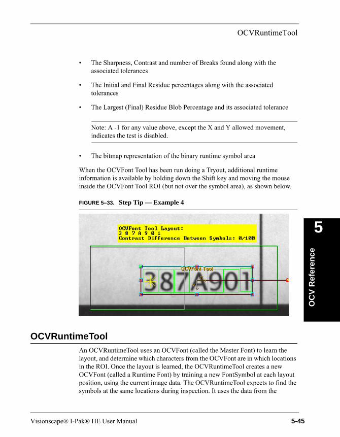
OCVRuntimeTool
OC
V R
efer
ence
5
• The Sharpness, Contrast and number of Breaks found along with the associated tolerances
• The Initial and Final Residue percentages along with the associated tolerances
• The Largest (Final) Residue Blob Percentage and its associated tolerance
Note: A -1 for any value above, except the X and Y allowed movement, indicates the test is disabled.
• The bitmap representation of the binary runtime symbol area
When the OCVFont Tool has been run doing a Tryout, additional runtime information is available by holding down the Shift key and moving the mouse inside the OCVFont Tool ROI (but not over the symbol area), as shown below.
FIGURE 5–33. Step Tip — Example 4
OCVRuntimeToolAn OCVRuntimeTool uses an OCVFont (called the Master Font) to learn the layout, and determine which characters from the OCVFont are in which locations in the ROI. Once the layout is learned, the OCVRuntimeTool creates a new OCVFont (called a Runtime Font) by training a new FontSymbol at each layout position, using the current image data. The OCVRuntimeTool expects to find the symbols at the same locations during inspection. It uses the data from the
Visionscape® I-Pak® HE User Manual 5-45
Chapter 5 OCV Reference
Runtime Font to verify the quality and correctness of the characters being inspected. Because the train image creates templates, this code should be of good quality.
TrainingTraining of the OCVRuntimeTool involves placing and sizing the OCVRuntimeTool box around the area containing the symbols to be inspected. When Train is clicked, the ROI is scanned for symbol candidates. Symbol candidates are determined by searching for each symbol that is in the selected Master OCVFont (chosen through the LayoutStep). When all candidates have been found, a new OCVFont is created and a new symbol is trained and added to this Runtime Font for each candidate position.
Then, the OCVRuntimeTool box is reset based on the bounding rectangle of all symbols found and the values of the search extra properties. The AutoFind is trained automatically whenever the OCVRuntimeTool is trained. When the AutoFind Search Area Box is moved and/or sized, it is automatically retrained, without requiring retraining of the OCVRuntimeTool.
InspectionIf AutoFind is enabled, the pins are located and the OCVRuntimeTool box is repositioned based on the pin locations. Each of the symbols found during training is expected to be at the same location within the OCVRuntimeTool box at runtime. For each symbol position, there are several ways that an inspection can fail:
• The symbol cannot be located.
• The symbol can fail because the sharpness value is out of tolerance.
• The symbol can fail because the contrast value is out of tolerance.
• The symbol can fail because a break larger than the user-specified size appears in the character.
• The symbol failed an ID Test. It could not be determined that the correct symbol was present.
• The symbol can fail the initial residue check.
• The symbol can fail the final residue check, either or both methods. This residue analysis allows for detection of the following:
5-46 Visionscape® I-Pak® HE User Manual
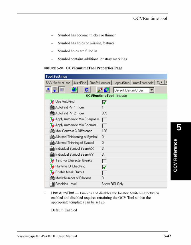
OCVRuntimeTool
OC
V R
efer
ence
5
– Symbol has become thicker or thinner
– Symbol has holes or missing features
– Symbol holes are filled in
– Symbol contains additional or stray markings
FIGURE 5–34. OCVRuntimeTool Properties Page
• Use AutoFind — Enables and disables the locator. Switching between enabled and disabled requires retraining the OCV Tool so that the appropriate templates can be set up.
Default: Enabled
Visionscape® I-Pak® HE User Manual 5-47

Chapter 5 OCV Reference
• AutoFind Pin 1 Index — Allows selection of the symbol position that trains the templates for AutoFind Pin 1.
– When set to a value less than or equal to 1, the first symbol position is used.
– When set to a value greater than or equal to the number of trained symbols, the last symbol position is used.
Default: 1 (use the first symbol)Range: 1 to n, where n is greater than or equal to the number of
trained symbols
• AutoFind Pin 2 Index — Allows selection of the symbol position that trains the templates for AutoFind Pin 2 (when the AutoFind is set up as a 2PinFind).
– When set to a value less than or equal to 1, the first symbol position is used.
– When set to a value greater than or equal to the number of trained symbols, the last symbol position is used.
Default: 999 (use the last symbol)Range: 1 to n, where n is greater than or equal to the number of
trained symbols
• Apply Automatic Min Sharpness — Allows the FontSymbols trained and added to the Runtime Font to have a sharpness tolerance automatically calculated for them. This automatically calculated tolerance is equal to 65% of the sharpness value calculated using the trained template.
Default: Disabled
• Apply Automatic Min Contrast — Allows the FontSymbols trained and added to the Runtime Font to have a contrast tolerance automatically calculated for them. This automatically calculated tolerance is equal to 50% of the contrast value calculated using the trained template.
Default: Disabled
• Allowed Thickening of Symbol — Determines the number of pixels that a symbol is allowed to grow along its perimeter. Residue will be ignored if it is found in the region between the edge of the symbol and the set number of
5-48 Visionscape® I-Pak® HE User Manual

OCVRuntimeTool
OC
V R
efer
ence
5
pixels away from the edge, in the direction away from the center of the symbol.
Default: 0 pixelsRange: 0 to 10 pixels
• Allowed Thinning of Symbol — Determines the number of pixels that a symbol is allowed to shrink along its perimeter. Residue will be ignored if it is found in the region between the edge of the symbol and the set number of pixels away from the edge, in the direction toward the center of the symbol.
Default: 0 pixelsRange: 0 to 10 pixels
• Max Contrast % Difference — Sets the maximum percentage difference between the calculated contrast values for symbols being inspected by the tool. When set to 100%, any contrast difference is acceptable. If no contrast calculations are performed for the inspected symbols, the calculated percent difference is 0. Otherwise, the smallest contrast from the inspected symbols is divided by the largest contrast from the inspected symbols. This value is then subtracted from 1 to get the percentage difference. If the calculated difference is larger than the value of Max Contrast % Difference, the inspection fails.
Default: 100%Range: 0 to 100%
• Individual Symbol Search X — Determines the width of the search area for individual symbols. This number is doubled and added to the symbol width to get the search width.
Default: 3 pixelsRange: 0 to 50 pixels
• Individual Symbol Search Y — Determines the height of the search area for individual symbols. This number is doubled and added to the symbol height to get the search height.
Default: 3 pixelsRange: 0 to 50 pixels
• Test For Character Breaks — Enables and disables the checks for character break appearance flaws.
Visionscape® I-Pak® HE User Manual 5-49
Chapter 5 OCV Reference
Default: Disabled
• Runtime ID Checking — Enables and disables the tests that determine if the correct symbol is present at runtime. During training of an OCVFont, the FontSymbols that are added are checked against each other to determine how similar they are. When FontSymbols are found to be very similar, tests for determining the presence of the correct symbol are set up and stored with the FontSymbols. These tests are only performed at runtime when Runtime ID Checking is enabled.
Note: Microscan highly recommends that you do not use Automatic Segmentation, that is, leave its setting in its default position of Off, and carefully use symbol boxes of equal size for all special characters like O, 0, B, 8, D, and so on.
Default: Enabled
• Enable Mask Output — Enables and disables the creation and output of a mask at runtime. This property is used in conjunction with the DynamMask Tool to allow the printed characters to be excluded (masked out) from other image processing. Enabling this property increases inspection time.
Default: Disabled
• Mask:Number of Dilations — Sets the number of expansions that are performed on the output mask. This property is used in conjunction with the DynamMask Tool to allow the printed characters to be excluded (masked out) from other image processing.
Default: 1
• Graphics Level — Sets up different levels of debug graphics at runtime. The default Show ROI Only will only show the ROI boxes associated with the OCVRuntimeTool and the characters being inspected (green for passed, red for failed).
– When set to Show None, no graphics are shown at runtime.
– When set to Show Basic Graphics, a number indicating the symbol's position in the layout is shown, along with the ROI boxes, as shown in Figure 5–35.
5-50 Visionscape® I-Pak® HE User Manual
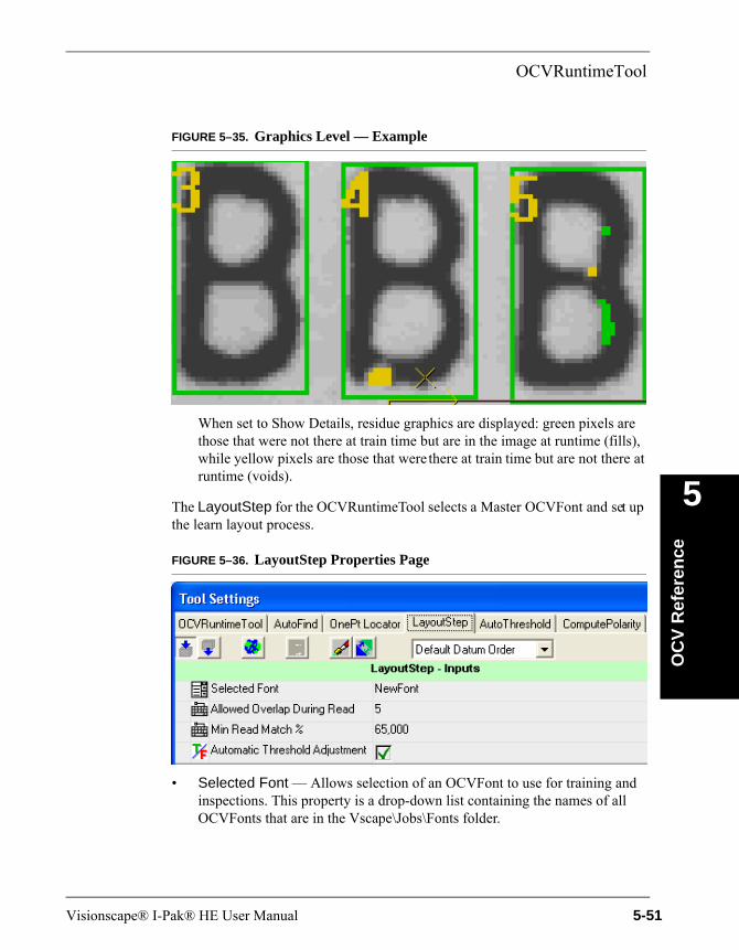
OCVRuntimeTool
OC
V R
efer
ence
5
FIGURE 5–35. Graphics Level — Example
When set to Show Details, residue graphics are displayed: green pixels are those that were not there at train time but are in the image at runtime (fills), while yellow pixels are those that were there at train time but are not there at runtime (voids).
The LayoutStep for the OCVRuntimeTool selects a Master OCVFont and set up the learn layout process.
FIGURE 5–36. LayoutStep Properties Page
• Selected Font — Allows selection of an OCVFont to use for training and inspections. This property is a drop-down list containing the names of all OCVFonts that are in the Vscape\Jobs\Fonts folder.
Visionscape® I-Pak® HE User Manual 5-51
Chapter 5 OCV Reference
• Allowed Overlap During Read — Used during the learn layout process. The value of this property specifies the amount of symbol candidate ROI overlap that is allowed. When symbol candidates overlap more than the allowed value, tests are performed to determine the best candidate at the overlap position. The other candidate will not become part of the layout. This overlap measurement is in pixels.
Default: 5 pixelsRange: 0 to 15 pixels
• Min Read Match % — Is a correlation percentage used as a minimum requirement for a symbol to be considered a candidate during the learn layout process.
Default: 65%Range: 0% to 100%
• Automatic Threshold Adjustment — Enables and disables the automatic threshold adjustment feature. When enabled, the best match location during the learn layout process calculates an adjustment to the threshold used to create binary images at runtime. This calculated value is set in the Threshold Adjustment property (AutoThreshold tab).
The AutoThreshold tab of the OCVRuntimeTool belongs to the LayoutStep and is used only at runtime. The only property used is the Threshold Adjustment property, which serves as a global adjustment for all FontSymbols being inspected. FontSymbols may still make individual adjustments to the thresholds using their own Auto Threshold Adjustment properties.
The ComputePolarity step of the OCVRuntimeTool belongs to the LayoutStep. It is not used by an OCVFont Tool.
Step TipsAfter the OCVRuntimeTool has been trained, positioning the mouse over the ROI displays a Step Tip. This Step Tip provides information and graphical feedback for individual symbols when the mouse is over a symbol area. Train information includes the Area of the symbol, the number of On pixels in the binary template, and a bitmap representation of the binary template, as shown in Figure 5–37.
5-52 Visionscape® I-Pak® HE User Manual

OCVRuntimeTool
OC
V R
efer
ence
5
FIGURE 5–37. Step Tip — Example 1
When the mouse is not positioned over a particular symbol area, the Step Tip displays the currently trained Layout Characters, or just the name of the OCVRuntimeTool when it is not trained, as shown in Figure 5–38.
FIGURE 5–38. Step Tip — Example 2
When the OCVRuntimeTool has been run using Tryout, additional runtime information is available by holding down the Shift key when the mouse is positioned over the symbol area, as shown in Figure 5–39.
FIGURE 5–39. Step Tip — Example 3
Visionscape® I-Pak® HE User Manual 5-53
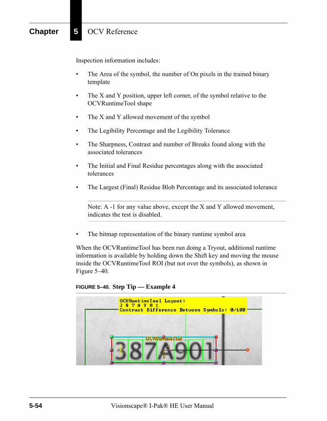
Chapter 5 OCV Reference
Inspection information includes:
• The Area of the symbol, the number of On pixels in the trained binary template
• The X and Y position, upper left corner, of the symbol relative to the OCVRuntimeTool shape
• The X and Y allowed movement of the symbol
• The Legibility Percentage and the Legibility Tolerance
• The Sharpness, Contrast and number of Breaks found along with the associated tolerances
• The Initial and Final Residue percentages along with the associated tolerances
• The Largest (Final) Residue Blob Percentage and its associated tolerance
Note: A -1 for any value above, except the X and Y allowed movement, indicates the test is disabled.
• The bitmap representation of the binary runtime symbol area
When the OCVRuntimeTool has been run doing a Tryout, additional runtime information is available by holding down the Shift key and moving the mouse inside the OCVRuntimeTool ROI (but not over the symbols), as shown in Figure 5–40.
FIGURE 5–40. Step Tip — Example 4
5-54 Visionscape® I-Pak® HE User Manual

OCVFontless Tool
OC
V R
efer
ence
5
OCVFontless ToolAn OCVFontless Tool does not require an OCVFont. Instead, it determines the location of characters in the FOV using a blob-analysis technique. Then, it stores training data for each character location as an OCVSymbolStep. The OCVFontless Tool expects to find the symbols at the same locations during inspection. It uses the trained data to verify the quality of the characters being inspected.
TrainingTraining the OCVFontless Tool involves placing and sizing the OCVFontless Tool box around the area containing the symbols to be inspected. When Train is clicked, the ROI is scanned for symbol candidates. A symbol candidate is a group of connected pixels that have foreground polarity. Each symbol candidate that contains enough pixels, as defined by the Min Symbol Size in pixels parameter, is trained and stored as an OCVSymbolStep.
Then, the OCVFontless Tool box is reset based on the bounding rectangle of all symbols found and the values of the search extra properties. The AutoFind is trained automatically whenever the OCVFontless Tool is trained. When the AutoFind Search Area Box is moved and/or sized, it is automatically retrained, without requiring retraining of the OCVFontless Tool.
InspectionWhen AutoFind is enabled, the pins are located and the OCVFontless Tool box is re-positioned based on the pin locations. Each symbol found during training is expected to be at the same location within the OCVFontless Tool box at runtime. For each symbol position, there are several ways that an inspection can fail:
• The symbol cannot be located.
• The symbol can fail because the sharpness value is out of tolerance.
• The symbol can fail because the contrast value is out of tolerance.
• The symbol can fail because a break larger than the user-specified size appears in the character.
• The symbol can fail the initial residue check.
• The symbol can fail the final residue check, either or both methods. This residue analysis allows for detection of the following:
Visionscape® I-Pak® HE User Manual 5-55
Chapter 5 OCV Reference
– Symbol has become thicker or thinner
– Symbol has holes or missing features
– Symbol holes are filled in
– Symbol contains additional or stray markings
5-56 Visionscape® I-Pak® HE User Manual
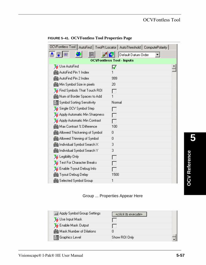
OCVFontless Tool
OC
V R
efer
ence
5
FIGURE 5–41. OCVFontless Tool Properties Page
Group ... Properties Appear Here
Visionscape® I-Pak® HE User Manual 5-57
Chapter 5 OCV Reference
• Use AutoFind — Enables and disables the locator. Switching between enabled and disabled requires retraining the OCV Tool so that the appropriate templates can be set up.
Default: Enabled
• AutoFind Pin 1 Index — Allows selection of the symbol position that trains the templates for AutoFind Pin 1.
– When set to a value less than or equal to 1, the first symbol position is used.
– When set to a value greater than or equal to the number of trained symbols, the last symbol position is used.
Default: 1, meaning use the first symbolRange: 1 to n, where n is greater than or equal to the number of
trained symbols
• AutoFind Pin 2 Index — Allows selection of the symbol position that trains the templates for AutoFind Pin 2, when the AutoFind is set up as a 2PinFind.
– When set to a value less than or equal to 1, the first symbol position is used.
– When set to a value greater than or equal to the number of trained symbols, the last symbol position is used.
Default: 999, meaning use the last symbolRange: 1 to n, where n is greater than or equal to the number of
trained symbols
• Min Symbol Size in pixels — Adjusts the minimum size that a blob must be in order to be considered a symbol.
Default: 20 pixelsRange: 5 to 256 pixels
• Find Symbols That Touch ROI — When enabled, symbols are trained for blobs that are not fully within the ROI. When disabled, blobs that are not fully within the ROI are ignored.
Default: Disabled
5-58 Visionscape® I-Pak® HE User Manual
OCVFontless Tool
OC
V R
efer
ence
5
• Num of Border Spaces to Add — Determines how many pixels to allow between actual character pixels and the edge of the box that defines the OCVSymbolStep.
Default: 1 pixelsRange: 0 to 19 pixels
• Symbol Sorting Sensitivity — Adjusts the sensitivity of the sorting of symbols into rows during training. The sorting is based on the positions of the symbols.
– Highest — The allowed separation is decreased to 10% of the average height.
– High — The allowed separation is decreased to 25% of the average height.
– Normal — (Default) Any two symbols whose top Y positions are separated by more than 50% of the average height of all trained symbols will be considered to be on separate rows.
– Low — The allowed separation is increased to 75% of the average height.
– Lowest — The allowed separation is increased to 90% of the average height.
• Single OCV Symbol Step — When enabled, the OCVFontless Tool trains a single OCVSymbolStep that includes all the symbols of the mark that are within the mark area box. When disabled, the OCVFontless Tool trains an OCVSymbolStep for each symbol of the mark that is located within the mark area box.
Default: Disabled
• Apply Automatic Min Sharpness — Allows the OCVSymbolSteps trained to have a sharpness tolerance automatically calculated for them. This automatically calculated tolerance is equal to 65% of the sharpness value calculated using the trained template.
Default: Disabled
• Apply Automatic Min Contrast — Allows the OCVSymbolSteps trained to have a contrast tolerance automatically calculated for them. This
Visionscape® I-Pak® HE User Manual 5-59
Chapter 5 OCV Reference
automatically calculated tolerance is equal to 50% of the contrast value calculated using the trained template.
Default: Disabled
• Max Contrast % Difference — Sets the maximum percentage difference between the calculated contrast values for symbols being inspected by the tool. When set to 100%, any contrast difference is acceptable. If no contrast calculations are performed for the inspected symbols, the calculated percent difference is 0. Otherwise, the smallest contrast from the inspected symbols is divided by the largest contrast from the inspected symbols. This value is then subtracted from 1 to get the percentage difference. If the calculated the difference is larger than the value of Max Contrast % Difference, the inspection fails.
Default: 100%Range: 0 to 100%
• Allowed Thickening of Symbol — Determines the number of pixels that a symbol is allowed to grow along its perimeter. Residue will be ignored if it is found in the region between the edge of the symbol and the set number of pixels away from the edge, in the direction away from the center of the symbol.
Default: 0 pixelsRange: 0 to 10 pixels
• Allowed Thinning of Symbol — Determines the number of pixels that a symbol is allowed to shrink along its perimeter. Residue will be ignored if it is found in the region between the edge of the symbol and the set number of pixels away from the edge, in the direction toward the center of the symbol.
Default: 0 pixelsRange: 0 to 10 pixels
• Individual Symbol Search X — Determines the width of the search area for individual symbols. This number is doubled and added to the symbol width to get the search width.
Default: 3 pixelsRange: 0 to 50 pixels
5-60 Visionscape® I-Pak® HE User Manual

OCVFontless Tool
OC
V R
efer
ence
5
• Individual Symbol Search Y — Determines the height of the search area for individual symbols. This number is doubled and added to the symbol height to get the search height.
Default: 3 pixelsRange: 0 to 50 pixels
• Test For Character Breaks — Enables and disables the checks for character break appearance flaws.
Default: Disabled
• Enable Tryout Debug Info — Enables and disables the display of debug information during tryout. When enabled, inspection data is displayed on the Output line for each OCVSymbol that is part of the OCVFontless Tool.
Default: Disabled
• Tryout Debug Delay — Sets a delay that is used during the display of debug information. This delay is the minimum amount of time that the information is displayed.
Default: 1500 ms
• Selected Symbol Group — Selects which symbol group has its symbol properties displayed on the properties page. Changing this value updates the property page to display the correct symbol group properties.
Symbol groups are defined based on the number of On pixels in the templates of the symbols. The grouping of symbols is accomplished by setting a range of values, Group Min Pixels and Group Max Pixels, for a group. By default, only one symbol group is defined. This group contains all OCVSymbolSteps because the range is automatically set to a minimum of 0 pixels and a maximum of 307200, maximum possible in a 640x480 symbol.
The groups are defined in order of maximum character pixels, so that group 2’s Group Min Pixels property is always equal to group 1’s Group Max Pixels property plus one, group 3’s Group Min Pixels property is always equal to group 2’s Group Max Pixels property plus one, etc. The final group is always defined to have a Group Max Pixels equal to 307200.
To add a group, change Group Max Pixels of the current group from 307200 to a lower value.
Visionscape® I-Pak® HE User Manual 5-61
Chapter 5 OCV Reference
The Group properties (Group...) on the OCVFontless Tool property page can be set on a group basis. Refer to “OCVSymbolStep” on page 5-67 for more information.
• Apply Symbol Group Settings — Sets the group parameters for the currently selected group to the current values in the group properties.
• Use Input Mask — This property is applicable only when the OCVFontless Tool has a child step that produces a mask buffer as an output. When such a child step is inserted into the OCVFontless Tool, Use Input Mask is automatically enabled. When enabled, the OCVFontless Tool must be trained. After it is trained, the mask pixels are highlighted in red. When disabled, this property will allow the OCVFontless Tool to retain the child mask-generating step but does not apply the mask at runtime.
Default: Disabled
• Enable Mask Output — Enables and disables the creation and output of a mask at runtime. This property is used in conjunction with the DynamMask Tool to allow the printed characters to be excluded, masked out, from other image processing.
Default: Disabled
• Mask:Number of Dilations — Sets the number of expansions that are performed on the output mask. This property is used in conjunction with the DynamMask Tool to allow the printed characters to be excluded, masked out, from other image processing.
Default: Disabled
• Graphics Level — Sets up different levels of debug graphics at runtime. The default Show ROI Only only shows the ROI boxes associated with the OCVFontless Tool and the characters being inspected, green for passed, red for failed. When set to:
– Show None, no graphics are shown at runtime.
– Show Basic Graphics, a number indicating the symbol’s position in the layout is shown, along with the ROI boxes, as shown in Figure 5–42.
5-62 Visionscape® I-Pak® HE User Manual
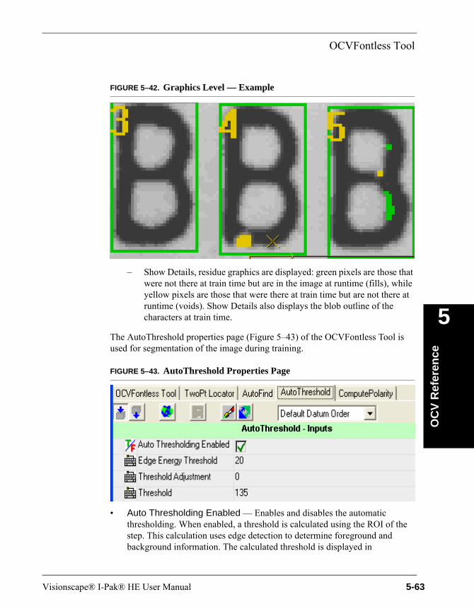
OCVFontless Tool
OC
V R
efer
ence
5
FIGURE 5–42. Graphics Level — Example
– Show Details, residue graphics are displayed: green pixels are those that were not there at train time but are in the image at runtime (fills), while yellow pixels are those that were there at train time but are not there at runtime (voids). Show Details also displays the blob outline of the characters at train time.
The AutoThreshold properties page (Figure 5–43) of the OCVFontless Tool is used for segmentation of the image during training.
FIGURE 5–43. AutoThreshold Properties Page
• Auto Thresholding Enabled — Enables and disables the automatic thresholding. When enabled, a threshold is calculated using the ROI of the step. This calculation uses edge detection to determine foreground and background information. The calculated threshold is displayed in
Visionscape® I-Pak® HE User Manual 5-63
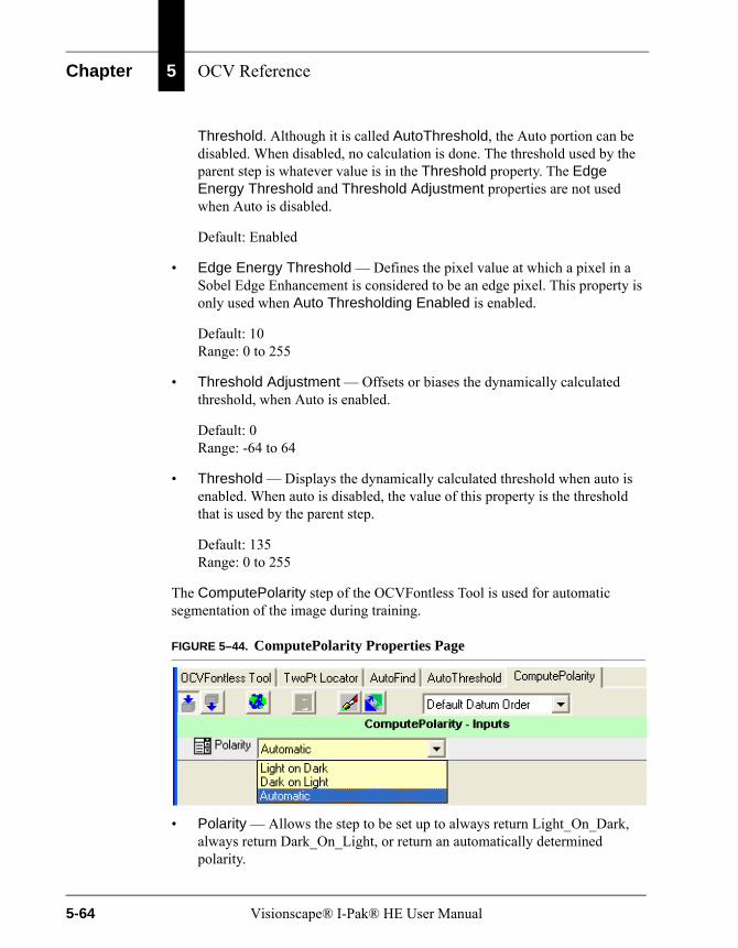
Chapter 5 OCV Reference
Threshold. Although it is called AutoThreshold, the Auto portion can be disabled. When disabled, no calculation is done. The threshold used by the parent step is whatever value is in the Threshold property. The Edge Energy Threshold and Threshold Adjustment properties are not used when Auto is disabled.
Default: Enabled
• Edge Energy Threshold — Defines the pixel value at which a pixel in a Sobel Edge Enhancement is considered to be an edge pixel. This property is only used when Auto Thresholding Enabled is enabled.
Default: 10Range: 0 to 255
• Threshold Adjustment — Offsets or biases the dynamically calculated threshold, when Auto is enabled.
Default: 0Range: -64 to 64
• Threshold — Displays the dynamically calculated threshold when auto is enabled. When auto is disabled, the value of this property is the threshold that is used by the parent step.
Default: 135Range: 0 to 255
The ComputePolarity step of the OCVFontless Tool is used for automatic segmentation of the image during training.
FIGURE 5–44. ComputePolarity Properties Page
• Polarity — Allows the step to be set up to always return Light_On_Dark, always return Dark_On_Light, or return an automatically determined polarity.
5-64 Visionscape® I-Pak® HE User Manual

OCVFontless Tool
OC
V R
efer
ence
5
Default: Automatic
Step TipsAfter the OCVFontless Tool has been trained, positioning the mouse over the ROI displays a Step Tip. This Step Tip provides information and graphical feedback for individual symbols when the mouse is over a symbol area. Train information includes the Area of the symbol, the number of On pixels in the binary template, and a bitmap representation of the binary template, as shown in Figure 5–45.
FIGURE 5–45. Step Tip — Example 1
When the mouse is not positioned over a particular symbol area, the Step Tip displays the name of the OCVFontless Tool, as shown in Figure 5–46.
FIGURE 5–46. Step Tip — Example 2
Visionscape® I-Pak® HE User Manual 5-65

Chapter 5 OCV Reference
When the OCVFontless Tool has been run, additional runtime information is available by holding down the Shift key when the mouse is positioned over the symbol area, as shown in Figure 5–47.
FIGURE 5–47. Step Tip — Example 3
Inspection information includes:
• The Area of the symbol, the number of On pixels in the trained binary template
• The X and Y position, upper left corner, of the symbol relative to the OCVRuntimeTool shape
• The X and Y allowed movement of the symbol
• The Legibility Percentage and the Legibility Tolerance
• The Sharpness, Contrast and number of Breaks found along with the associated tolerances
• The Initial and Final Residue percentages along with the associated tolerances
• The Largest (Final) Residue Blob Percentage and its associated tolerance
5-66 Visionscape® I-Pak® HE User Manual
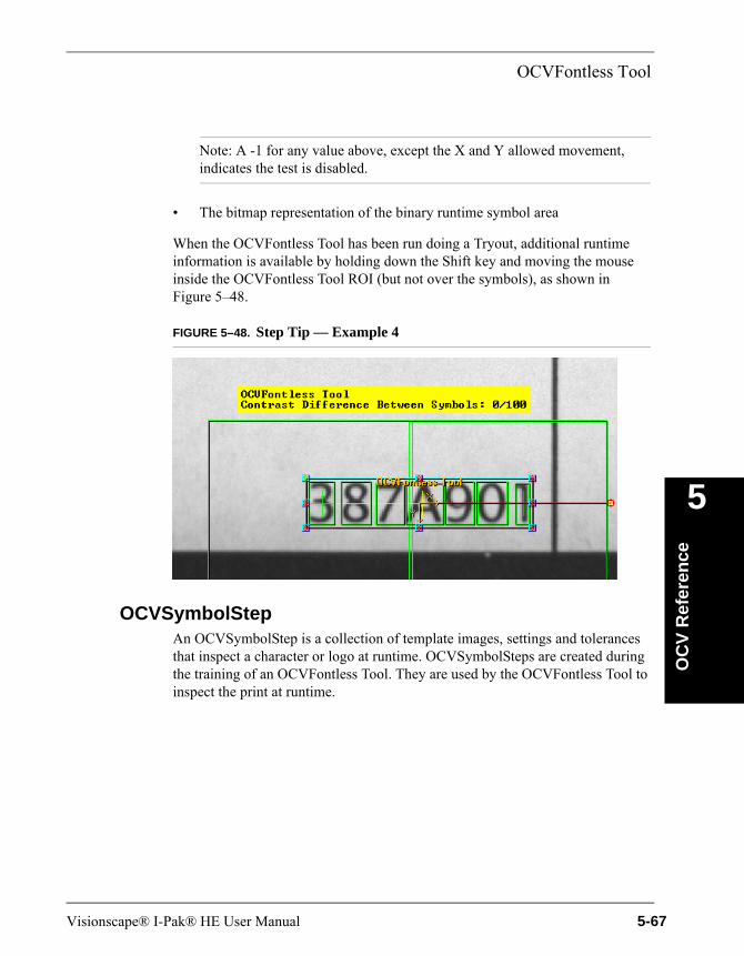
OCVFontless Tool
OC
V R
efer
ence
5
Note: A -1 for any value above, except the X and Y allowed movement, indicates the test is disabled.
• The bitmap representation of the binary runtime symbol area
When the OCVFontless Tool has been run doing a Tryout, additional runtime information is available by holding down the Shift key and moving the mouse inside the OCVFontless Tool ROI (but not over the symbols), as shown in Figure 5–48.
FIGURE 5–48. Step Tip — Example 4
OCVSymbolStepAn OCVSymbolStep is a collection of template images, settings and tolerances that inspect a character or logo at runtime. OCVSymbolSteps are created during the training of an OCVFontless Tool. They are used by the OCVFontless Tool to inspect the print at runtime.
Visionscape® I-Pak® HE User Manual 5-67
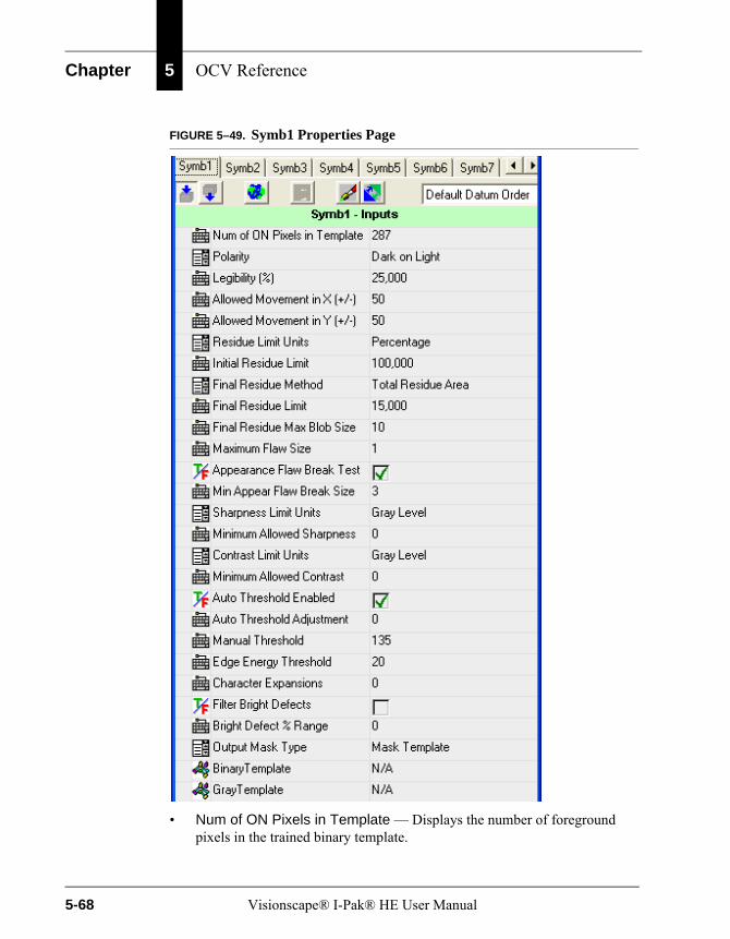
Chapter 5 OCV Reference
FIGURE 5–49. Symb1 Properties Page
• Num of ON Pixels in Template — Displays the number of foreground pixels in the trained binary template.
5-68 Visionscape® I-Pak® HE User Manual

OCVFontless Tool
OC
V R
efer
ence
5
• Polarity — Allows the step to always train with polarity Light_On_Dark, or always train with polarity Dark_On_Light. The default is set by the OCVFontless Tool during training.
• Legibility (%) — Passes/fails the symbol based on this minimum correlation percentage. The symbol will fail inspection when the correlation percentage is less than this value.
Default: 25%Range: 0% to 100%
• Allowed Movement in X (+/-) — Sets the maximum number of pixels that a symbol can move in the X-axis (relative to other symbols) from its trained position.
Default: 50 pixels (any movement is allowed)Range: 0 to 50 pixels. The maximum of 50 pixels comes from the parent OCVTool setting Individual Symbol Search X, which limits the search range in X to a maximum of 50 pixels in either direction.
• Allowed Movement in Y (+/-) — Set the maximum number of pixels that a symbol can move in the Y-axis (relative to other symbols) from its trained position.
Default: 50 pixels (any movement is allowed)Range: 0 to 50 pixels. The maximum of 50 pixels comes from the parent OCVTool setting Individual Symbol Search Y, which limits the search range in Y to a maximum of 50 pixels in either direction.
• Residue Limit Units — Inputs the residue limits in either a maximum pixel count value or a percentage value (percentage value is based on the number of On pixels in the trained template). When the value of this property changes, the values of Initial Residue Limit and Final Residue Limit are changed to match the selected units.
Default: Percentage
• Initial Residue Limit — Provides a quick check of the character quality and correctness. The initial residue calculation is done before any image processing is done on the residue image. When the system looks at the symbol being inspected, it determines the residue of the symbol, which is a count of those pixels that differ between the trained template and the current image. Based on the value of this property, the system determines if the
Visionscape® I-Pak® HE User Manual 5-69
Chapter 5 OCV Reference
residue is within tolerances. If it is not within tolerances, the symbol fails. Otherwise, the system continues on with the rest of the inspection procedure.
When Residue Limit Units is set to Percentage:
Default: 100.0%Range: 0.0% to 100.0%
The value of this property is the smallest percentage of residue pixels (relative to the trained On pixel count) in the inspected image that makes the symbol fail the inspection.
When Residue Limit Units is set to Pixels:
Default: symbol sizeRange: 0 to symbol size
The value of this property is the smallest count of residue pixels in the inspected image that makes the symbol fail the inspection.
This property is good for catching smudges that are aesthetically poor, but would pass after all inspection operations are performed on it. A value of 100% or symbol size means initial residue is ignored.
• Final Residue Method — Selects between three algorithms for final residue analysis:
– Total Residue Area — This is the default. This choice counts all On pixels in the residue image and use the value in Final Residue Limit, pixel or percent, as the tolerance.
– Max Residue Blob — Only counts the pixels in the largest blob of the residue image and use the value in Final Residue Max Blob Size as the tolerance.
– Both — Performs both methods.
• Final Residue Limit — Sets the amount of objectionable residue that is to be deemed passable when Final Residue Method is set to Total Residue Area or Both. Final residue calculation is done after the image processing on the residue image that is associated with Maximum Flaw Size.
If there is little information in a symbol, i.e., a 1 as compared to an L, the percentage variation allowed should be reduced. An assignment of 0% (residue pixel count = 0) means that no residue is passable. An assignment of
5-70 Visionscape® I-Pak® HE User Manual
OCVFontless Tool
OC
V R
efer
ence
5
100% (residue pixel count = symbol size) means that objectionable residue as large as the area of the prototype itself is passable.
When Residue Limit Units is set to Percentage:
Default: 15.0%, meaning 15% variation is acceptableRange: 0.0% to 100.0%
The value of this property is the smallest percentage of residue pixels (relative to the trained On pixel count) in the inspected image that makes the symbol fail the inspection.
When Residue Limit Units is set to Pixels:
Default: 15% of the symbol sizeRange: 0 to symbol size
The value of this property is the smallest count of residue pixels in the inspected image that makes the symbol fail the inspection.
Note: Determining the proper value for Final Residue Limit is a subjective decision; the higher the quality of the character/symbol desired, the lower the Final Residue Limit should be.
• Final Residue Max Blob Size — Used when Final Residue Method is set to Max Residue Blob or Both. A blob analysis is performed on the residue image and the largest blob is found. If this blob has an area that is greater than the value of this property, the symbol will fail the inspection.
Default: 10Range: 1 to 512
• Maximum Flaw Size — Represents the maximum width in pixels that a discrepancy is allowed to be before it is considered objectionable. The larger the number assigned, the larger a discrepancy is allowed before causing the symbol inspection to fail.
Default: 1Range: 0 to 20
• Appearance Flaw Break Test — Determines whether the OCVSymbolStep is to inspect for character breaks in the symbol. When
Visionscape® I-Pak® HE User Manual 5-71
Chapter 5 OCV Reference
enabled, the inspection fails if a break is found in the symbol. When disabled, the inspection ignores breaks in the symbol.
Default: Enabled
• Min Appear. Flaw Break Size — Is the smallest size break that causes a character break failure.
Default: 2 pixelsRange: 1 to 10 pixels
• Sharpness Limit Units — Sets the units for the “Minimum Allowed Sharpness” property.
– When set to Gray Level, the value of the “Minimum Allowed Sharpness” property is used as an absolute minimum value that the calculated sharpness value must be in order for the inspection to pass.
– When set to Percentage, the value of the “Minimum Allowed Sharpness” is used to calculate a percentage of the trained sharpness value, which is then used as an absolute minimum value that the calculated sharpness value must be in order for the inspection to pass.
– When switched from Gray Level to Percentage, the Minimum Allowed Sharpness property is updated to be the percentage value that corresponds to the gray level value that it previously held.
– When switched from Percentage to Gray Level, the Minimum Allowed Sharpness property is updated to be the gray level value that corresponds to the percentage value that it previously held.
Default: Gray Level
• Minimum Allowed Sharpness — Determines how crisp a symbol must be to pass inspection. It is measured by average edge strength over the entire symbol. Typical edge strengths are from 20 to 80 sharpness units.
Default: 0Range: 0 to 256 Gray Level or 0 to 100 Percentage
• Contrast Limit Units — Sets the units for the Minimum Allowed Contrast property.
5-72 Visionscape® I-Pak® HE User Manual

OCVFontless Tool
OC
V R
efer
ence
5
– When set to Gray Level, the value of the Minimum Allowed Contrast property is used as an absolute minimum value that the calculated contrast value must be in order for the inspection to pass.
– When set to Percentage, the value of the Minimum Allowed Contrast is used to calculate a percentage of the trained contrast value, which is then used as an absolute minimum value that the calculated contrast value must be in order for the inspection to pass.
– When switched from Gray Level to Percentage, the Minimum Allowed Contrast property is updated to be the percentage value that corresponds to the gray level value that it previously held.
– When switched from Percentage to Gray Level, the Minimum Allowed Contrast property is updated to be the gray level value that corresponds to the percentage value that it previously held.
Default: Gray Level
• Minimum Allowed Contrast — The Contrast is the measurement that defines the grayscale foreground to background relationship of the symbol data. To calculate the contrast value, the average gray level value of the background pixels is subtracted from the average gray level of the foreground pixels. Whenever Minimum Allowed Contrast has a value of 0, no contrast checks are performed.
Default: 0Range: 0 to 255 Gray Level or 0 to 100 Percentage
• Auto Threshold Enabled — Enables and disables the automatic calculation of a threshold for binarizing the image at both train and run time.
When enabled, the calculated threshold is displayed in the Manual Threshold property.
When disabled, no calculation is done. The threshold used for binarizing is whatever value is in the Manual Threshold property. Edge Energy Threshold and Threshold Adjustment are not used when this property is disabled.
Default: Enabled
• Auto Threshold Adjustment — Offsets or biases the dynamically calculated threshold, when Auto Threshold Enabled is enabled.
Visionscape® I-Pak® HE User Manual 5-73

Chapter 5 OCV Reference
Default: 0Range: -64 to 64
• Manual Threshold — Displays the dynamically calculated threshold when the Auto Threshold Enabled property is enabled. When Auto Threshold Enabled is disabled, Manual Threshold is the threshold that is used for binarizing the image.
Default: 135Range: 0 to 255
• Edge Energy Threshold — Defines the pixel value at which a pixel in a Sobel Edge Enhancement is considered to be an edge pixel. This property is only used when the Auto Threshold Enabled property is enabled.
Default: 10Range: 0 to 255
• Character Expansions — Useful when dealing with print from a dot matrix printer or any print that is broken up in segments. The more sparse the print, the higher the value of this property should be.
This property allows for the broken print to become solid by expanding the segments until they come together. Dilations expand each segment. Then, erosions decrease the size of the character in every direction except the direction in which the segments have connected. Dilations and erosions work together to make the segments solid without making the character fatter.
Default: 0Range: 0 to 9
• Filter Bright Defects — When enabled, runtime inspection of the symbol includes a pre-processing step for filtering out any bright defects in the image.
Default: Disabled
• Bright Defect % Range — Percentage that determines the threshold at which the bright defect filter processes. The threshold is calculated by taking this percentage of the range between the binarizing threshold and 255.
Default: 0 (binary threshold is used if Filter Bright Defects is enabled)Range: 0 to 100
5-74 Visionscape® I-Pak® HE User Manual
Substitute/Ignore
OC
V R
efer
ence
5
• Output Mask Type — Used in conjunction with the DynamicMask step. This property allows three selections:
– None — Adds nothing the mask.
– Mask Template — Only the foreground area of the symbol is added to the mask. This is the default.
– Mask ROI — The entire area within the symbol's ROI is added to the mask.
The remainder of this chapter discusses the following:
• “Substitute/Ignore” on page 5-75
• “Keyboard Input of Match String” on page 5-78
• “External Input of Match String” on page 5-82
• “Lot ChangeOver — CHANGELAYOUT Command” on page 5-90
• “OCV Tips” on page 5-105
• “Troubleshooting” on page 5-107
Substitute/IgnoreWhen training either an OCVFont Tool or OCVRuntimeTool, the Setup Mode Approve Inspect Characters dialog box (Figure 5–50) is displayed at the end of the learn layout. The string of layout characters is displayed at the top. This dialog box allows characters to be substituted into the layout or ignored entirely from the layout. Click Disapprove to return to the Setup Mode Train dialog box and retrain the current tool. Click Approve to accept the Inspect Chars: and return to the Setup Mode Train screen to train any remaining tools. Click Substitute to initiate the Substitute/Ignore window and modify the layout string.
Visionscape® I-Pak® HE User Manual 5-75
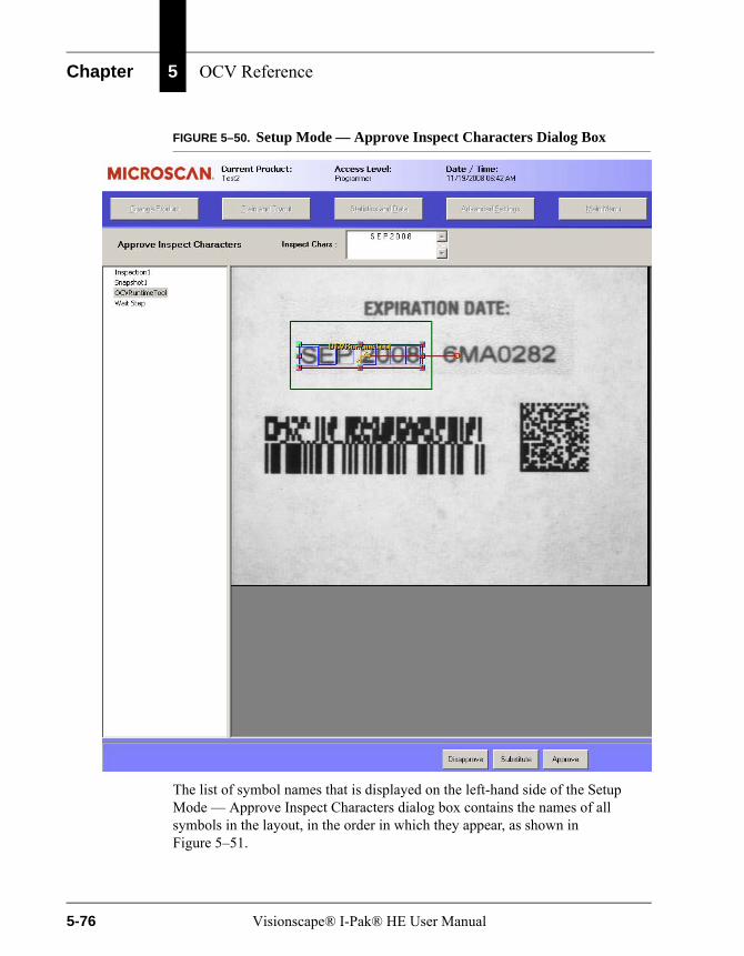
Chapter 5 OCV Reference
FIGURE 5–50. Setup Mode — Approve Inspect Characters Dialog Box
The list of symbol names that is displayed on the left-hand side of the Setup Mode — Approve Inspect Characters dialog box contains the names of all symbols in the layout, in the order in which they appear, as shown in Figure 5–51.
5-76 Visionscape® I-Pak® HE User Manual
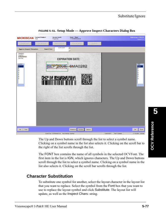
Substitute/Ignore
OC
V R
efer
ence
5
FIGURE 5–51. Setup Mode — Approve Inspect Characters Dialog Box
The Up and Down buttons scroll through the list to select a symbol name. Clicking on a symbol name in the list also selects it. Clicking on the scroll bar to the right of the list scrolls through the list.
The FONT box contains the name of all symbols in the selected OCVFont. The first item in the list is IGN, which ignores characters. The Up and Down buttons scroll through the list to select a symbol name. Clicking on a symbol name in the list also selects it. Clicking on the scroll bar scrolls through the list.
Character SubstitutionTo substitute one symbol for another, select the layout character in the layout list that you want to replace. Select the symbol from the Font box that you want to use to replace the layout symbol and click Substitute. The layout list will update, as well as the Inspect Chars: string.
Visionscape® I-Pak® HE User Manual 5-77
Chapter 5 OCV Reference
Ignoring a CharacterTo ignore one of the symbols in the layout and exclude it from being inspected at runtime, select the symbol to be ignored from the layout list. Select the IGN symbol from the Font box. Then, click Substitute. The symbol is removed from both the layout list and the Inspect Chars: string.
Finishing UpIf you are not satisfied with the layout and wish to retrain the tool, click Disapprove in the Setup Mode Train window with the OCVRuntimeTool still selected. You can adjust the properties of the tool and retrain until you achieve the desired layout string.
When you are satisfied with the layout shown in the Inspect Chars: string at the top of the window, click Approve to return to the Setup Mode Train window.
Keyboard Input of Match StringKeyboard Input of Match String allows you to specify the intended inspection string for an OCVFont Tool or OCVRuntimeTool. This is accomplished by displaying an input box into which you can type the necessary information.
Note: Enabling Keyboard Input of Match String mode automatically disables the ignore and substitute character functionality of I-PAK HE.
The OCVFontless Tool does not support the Keyboard Input of Match String feature.
Enabling Keyboard Input of Match StringAdvanced Settings > System Settings > Training and Results > Keyboard Input of Match String is a System Settings that will not change even when you do a change product to another Job that contains an OCVFont Tool or OCVRuntimeTool.
5-78 Visionscape® I-Pak® HE User Manual
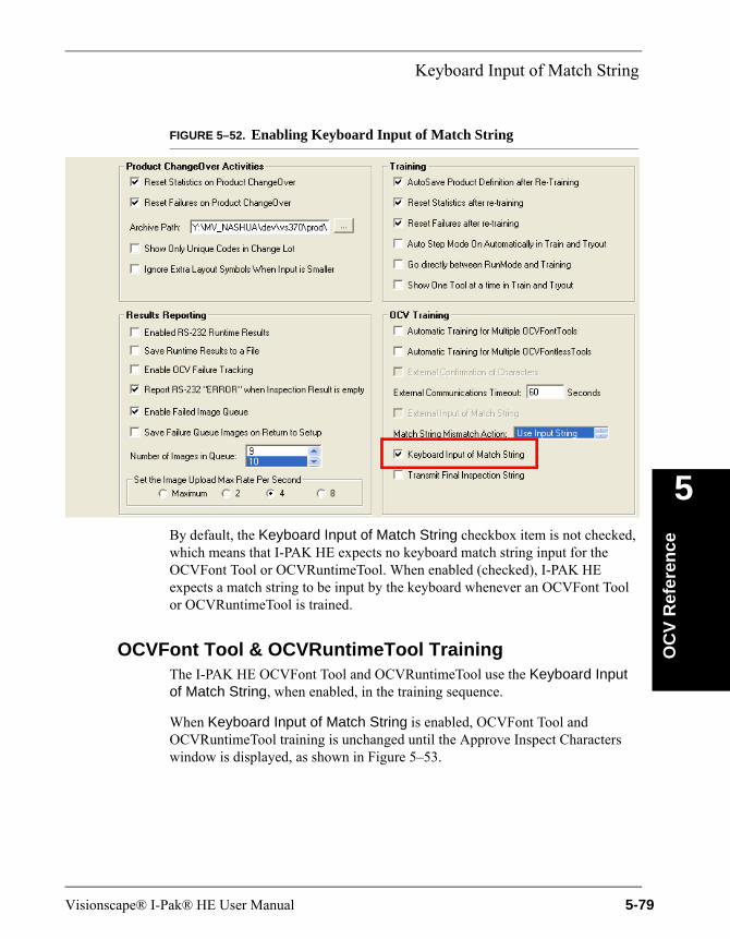
Keyboard Input of Match String
OC
V R
efer
ence
5
FIGURE 5–52. Enabling Keyboard Input of Match String
By default, the Keyboard Input of Match String checkbox item is not checked, which means that I-PAK HE expects no keyboard match string input for the OCVFont Tool or OCVRuntimeTool. When enabled (checked), I-PAK HE expects a match string to be input by the keyboard whenever an OCVFont Tool or OCVRuntimeTool is trained.
OCVFont Tool & OCVRuntimeTool TrainingThe I-PAK HE OCVFont Tool and OCVRuntimeTool use the Keyboard Input of Match String, when enabled, in the training sequence.
When Keyboard Input of Match String is enabled, OCVFont Tool and OCVRuntimeTool training is unchanged until the Approve Inspect Characters window is displayed, as shown in Figure 5–53.
Visionscape® I-Pak® HE User Manual 5-79
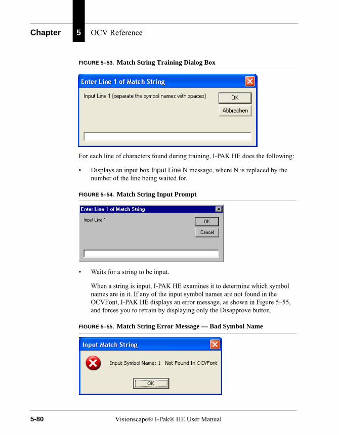
Chapter 5 OCV Reference
FIGURE 5–53. Match String Training Dialog Box
For each line of characters found during training, I-PAK HE does the following:
• Displays an input box Input Line N message, where N is replaced by the number of the line being waited for.
FIGURE 5–54. Match String Input Prompt
• Waits for a string to be input.
When a string is input, I-PAK HE examines it to determine which symbol names are in it. If any of the input symbol names are not found in the OCVFont, I-PAK HE displays an error message, as shown in Figure 5–55, and forces you to retrain by displaying only the Disapprove button.
FIGURE 5–55. Match String Error Message — Bad Symbol Name
5-80 Visionscape® I-Pak® HE User Manual
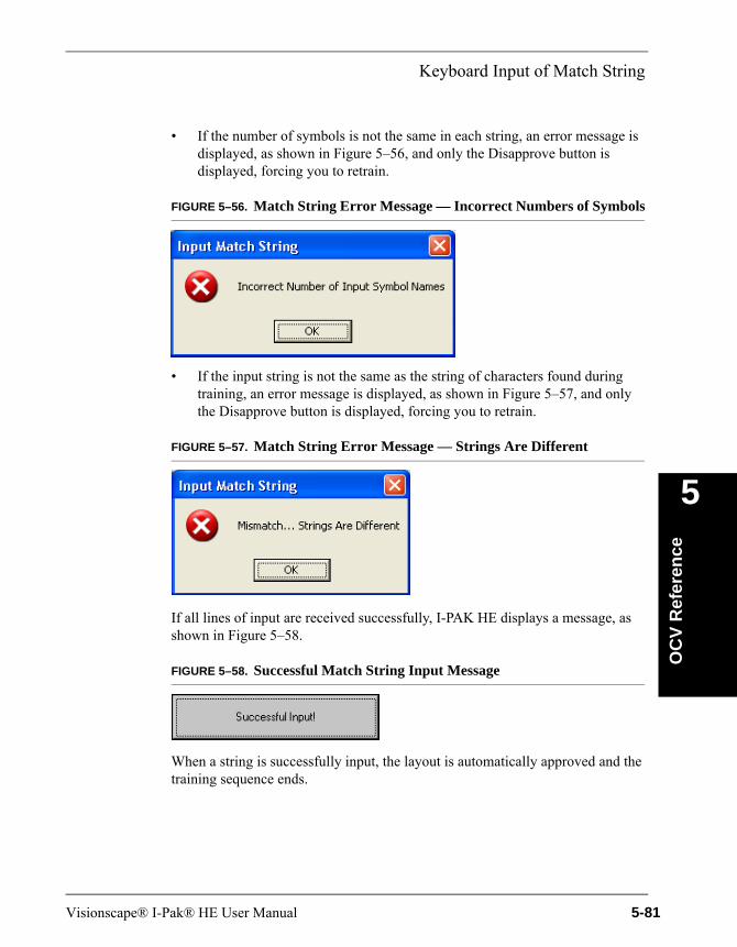
Keyboard Input of Match String
OC
V R
efer
ence
5
• If the number of symbols is not the same in each string, an error message is displayed, as shown in Figure 5–56, and only the Disapprove button is displayed, forcing you to retrain.
FIGURE 5–56. Match String Error Message — Incorrect Numbers of Symbols
• If the input string is not the same as the string of characters found during training, an error message is displayed, as shown in Figure 5–57, and only the Disapprove button is displayed, forcing you to retrain.
FIGURE 5–57. Match String Error Message — Strings Are Different
If all lines of input are received successfully, I-PAK HE displays a message, as shown in Figure 5–58.
FIGURE 5–58. Successful Match String Input Message
When a string is successfully input, the layout is automatically approved and the training sequence ends.
Visionscape® I-Pak® HE User Manual 5-81

Chapter 5 OCV Reference
Keyboard Input ProtocolThe I-PAK HE OCVFont Tool and OCVRuntimeTool uses a standard protocol in receiving the inspection string from you.
Inspection String ProtocolThe input inspection string is of the following form:
1<sp>2<sp>/<sp>2<sp>2<sp>/<sp>0<sp>2
The <sp> is a space character, which is the separator between symbol names.
External Input of Match StringMatch String allows an external device (computer, etc.,) to specify the intended inspection string for an OCVFont Tool or OCVRuntimeTool.
External Input of Match String is accomplished by creating a communications handshake between I-PAK HE and an external device. The necessary information is sent from the external device to I-PAK HE. The communications can be accomplished through RS-232 or Ethernet.
Note: Enabling Match String mode automatically disables the ignore and substitute character functionality of I-PAK HE.
The OCVFontless Tool does not support the Match String feature.
Enabling External Input of Match StringI-PAK HE software allows the External Input of Match String feature and related functionality to be enabled. By default, these features are disabled.
5-82 Visionscape® I-Pak® HE User Manual
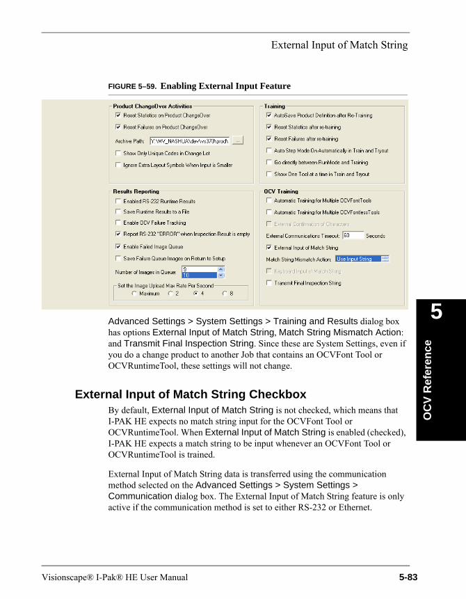
External Input of Match String
OC
V R
efer
ence
5
FIGURE 5–59. Enabling External Input Feature
Advanced Settings > System Settings > Training and Results dialog box has options External Input of Match String, Match String Mismatch Action: and Transmit Final Inspection String. Since these are System Settings, even if you do a change product to another Job that contains an OCVFont Tool or OCVRuntimeTool, these settings will not change.
External Input of Match String CheckboxBy default, External Input of Match String is not checked, which means that I-PAK HE expects no match string input for the OCVFont Tool or OCVRuntimeTool. When External Input of Match String is enabled (checked), I-PAK HE expects a match string to be input whenever an OCVFont Tool or OCVRuntimeTool is trained.
External Input of Match String data is transferred using the communication method selected on the Advanced Settings > System Settings > Communication dialog box. The External Input of Match String feature is only active if the communication method is set to either RS-232 or Ethernet.
Visionscape® I-Pak® HE User Manual 5-83
Chapter 5 OCV Reference
Match String Mismatch ActionI-PAK HE software allows the Mismatch Action to be selected. By default, the list box is set to Use Input String. This setting defines the action that I-PAK HE takes in the event that the string input from the external device does not match the string learned when the tool was trained. The possible selections and their meaning are:
• Use Input String — I-PAK HE uses the input string as the inspection string.
• Use Learned String — I-PAK HE ignores the input string and sets the string found during training as the inspection string.
• Retry by Learning — I-PAK HE forces you to retrain the tool and allow the string to be entered again.
• Retry by Input — I-PAK HE allows the string to be entered again.
The Match Mode Mismatch Action selected is applied to any OCVFont Tool or OCVRuntimeTool in the current Job.
Transmit Final Layout StringBy default, Transmit Final Inspection String is not checked, which means that I-PAK HE will not send the inspection string out when training of an OCVFont Tool or OCVRuntimeTool is complete. When Transmit Final Inspection String is enabled (checked), I-PAK HE sends the inspection string out to an external device whenever an OCVFont Tool or OCVRuntimeTool is trained successfully.
Transmit Final Inspection String data is transferred using the communication method selected on the Advanced Settings > System Settings > Communication dialog box. The Transmit Final Inspection String feature is only active if the communication method is set to either RS-232 or Ethernet.
OCVFont Tool & OCVRuntimeTool TrainingThe I-PAK HE OCVFont Tool and OCVRuntimeTool use the External Input of Match String and Transmit Final Inspection String features, when enabled, in the training sequence.
When External Input of Match String and/or Transmit Final Inspection String is enabled, OCVFont Tool and OCVRuntimeTool training is unchanged until the Approve Inspect Characters window is displayed. This window displays only one button, Input Match String, as shown in Figure 5–60.
5-84 Visionscape® I-Pak® HE User Manual
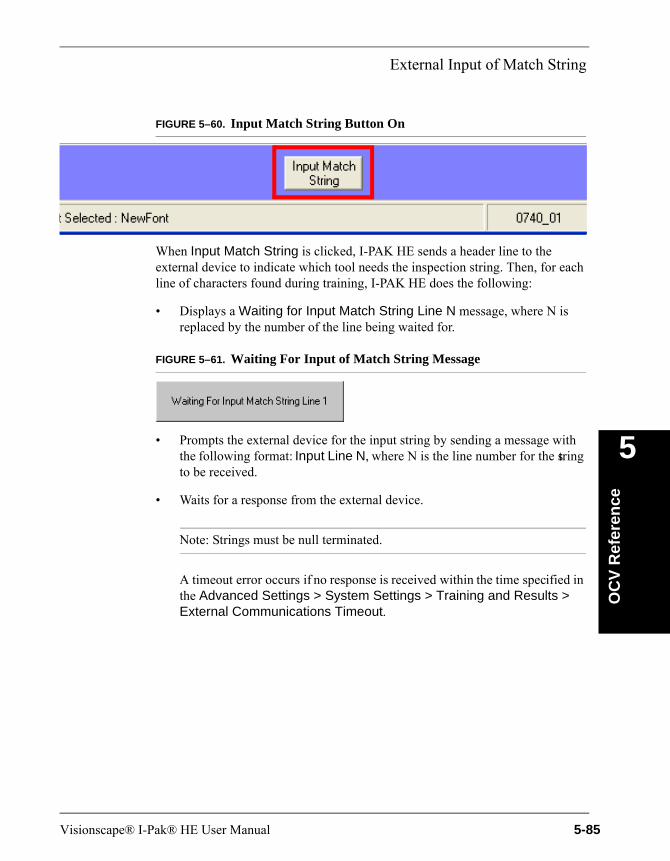
External Input of Match String
OC
V R
efer
ence
5
FIGURE 5–60. Input Match String Button On
When Input Match String is clicked, I-PAK HE sends a header line to the external device to indicate which tool needs the inspection string. Then, for each line of characters found during training, I-PAK HE does the following:
• Displays a Waiting for Input Match String Line N message, where N is replaced by the number of the line being waited for.
FIGURE 5–61. Waiting For Input of Match String Message
• Prompts the external device for the input string by sending a message with the following format: Input Line N, where N is the line number for the string to be received.
• Waits for a response from the external device.
Note: Strings must be null terminated.
A timeout error occurs if no response is received within the time specified in the Advanced Settings > System Settings > Training and Results > External Communications Timeout.
Visionscape® I-Pak® HE User Manual 5-85
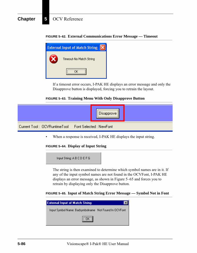
Chapter 5 OCV Reference
FIGURE 5–62. External Communications Error Message — Timeout
If a timeout error occurs, I-PAK HE displays an error message and only the Disapprove button is displayed, forcing you to retrain the layout.
FIGURE 5–63. Training Menu With Only Disapprove Button
• When a response is received, I-PAK HE displays the input string.
FIGURE 5–64. Display of Input String
The string is then examined to determine which symbol names are in it. If any of the input symbol names are not found in the OCVFont, I-PAK HE displays an error message, as shown in Figure 5–65 and forces you to retrain by displaying only the Disapprove button.
FIGURE 5–65. Input of Match String Error Message — Symbol Not in Font
5-86 Visionscape® I-Pak® HE User Manual
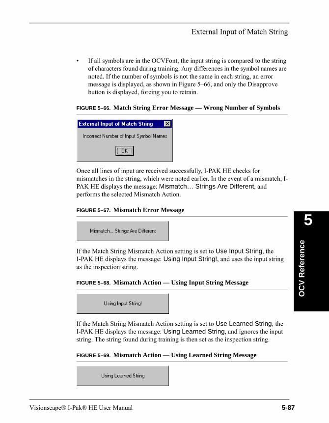
External Input of Match String
OC
V R
efer
ence
5
• If all symbols are in the OCVFont, the input string is compared to the string of characters found during training. Any differences in the symbol names are noted. If the number of symbols is not the same in each string, an error message is displayed, as shown in Figure 5–66, and only the Disapprove button is displayed, forcing you to retrain.
FIGURE 5–66. Match String Error Message — Wrong Number of Symbols
Once all lines of input are received successfully, I-PAK HE checks for mismatches in the string, which were noted earlier. In the event of a mismatch, I-PAK HE displays the message: Mismatch… Strings Are Different, and performs the selected Mismatch Action.
FIGURE 5–67. Mismatch Error Message
If the Match String Mismatch Action setting is set to Use Input String, the I-PAK HE displays the message: Using Input String!, and uses the input string as the inspection string.
FIGURE 5–68. Mismatch Action — Using Input String Message
If the Match String Mismatch Action setting is set to Use Learned String, the I-PAK HE displays the message: Using Learned String, and ignores the input string. The string found during training is then set as the inspection string.
FIGURE 5–69. Mismatch Action — Using Learned String Message
Visionscape® I-Pak® HE User Manual 5-87
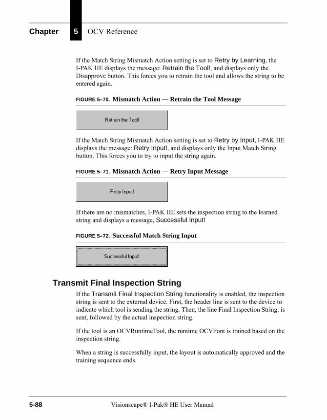
Chapter 5 OCV Reference
If the Match String Mismatch Action setting is set to Retry by Learning, the I-PAK HE displays the message: Retrain the Tool!, and displays only the Disapprove button. This forces you to retrain the tool and allows the string to be entered again.
FIGURE 5–70. Mismatch Action — Retrain the Tool Message
If the Match String Mismatch Action setting is set to Retry by Input, I-PAK HE displays the message: Retry Input!, and displays only the Input Match String button. This forces you to try to input the string again.
FIGURE 5–71. Mismatch Action — Retry Input Message
If there are no mismatches, I-PAK HE sets the inspection string to the learned string and displays a message, Successful Input!
FIGURE 5–72. Successful Match String Input
Transmit Final Inspection StringIf the Transmit Final Inspection String functionality is enabled, the inspection string is sent to the external device. First, the header line is sent to the device to indicate which tool is sending the string. Then, the line Final Inspection String: is sent, followed by the actual inspection string.
If the tool is an OCVRuntimeTool, the runtime OCVFont is trained based on the inspection string.
When a string is successfully input, the layout is automatically approved and the training sequence ends.
5-88 Visionscape® I-Pak® HE User Manual
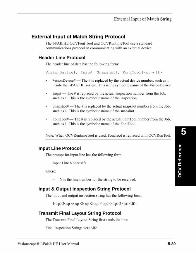
External Input of Match String
OC
V R
efer
ence
5
External Input of Match String ProtocolThe I-PAK HE OCVFont Tool and OCVRuntimeTool use a standard communications protocol in communicating with an external device.
Header Line ProtocolThe header line of data has the following form:
VisionDevice#, Insp#, Snapshot#, FontTool#<cr><lf>
• VisionDevice# — The # is replaced by the actual device number, such as 1 inside the I-PAK HE system. This is the symbolic name of the VisionDevice.
• Insp# — The # is replaced by the actual Inspection number from the Job, such as 1. This is the symbolic name of the Inspection.
• Snapshot# — The # is replaced by the actual snapshot number from the Job, such as 1. This is the symbolic name of the snapshot.
• FontTool# — The # is replaced by the actual FontTool number from the Job, such as 1. This is the symbolic name of the FontTool.
Note: When OCVRuntimeTool is used, FontTool is replaced with OCVRunTool.
Input Line ProtocolThe prompt for input line has the following form:
Input Line N<cr><lf>
where:
– N is the line number for the string to be received.
Input & Output Inspection String ProtocolThe input and output inspection string has the following form:
1<sp>2<sp>/<sp>2<sp>2<sp>/<sp>0<sp>2 <cr><lf>
Transmit Final Layout String ProtocolThe Transmit Final Layout String first sends the line:
Final Inspection String: <cr><lf>
Visionscape® I-Pak® HE User Manual 5-89
Chapter 5 OCV Reference
Then, send the inspection string above.
• <sp> is a space character, which is the separator between symbol names.
• <cr> is a decimal 13.
• <lf> is a decimal 10.
Lot ChangeOver — CHANGELAYOUT CommandAn extended feature of the OCVFont Tool is the ability to enter a new data string (Layout String) during Run Mode. This allows an automated Lot ChangeOver (CHANGELAYOUT Command) from an external RS-232 device or an external Ethernet device.
After training all the symbols in the OCVFont and training an OCVFont Tool, you can send a new string to inspect during Run Mode.
Setup Notes & Precautions
• You must stop triggering before sending a new inspect string.
• You must stop triggering and not restart it before Runmode IO is active.
• A maximum of one (1) input string is allowed in a single transmission. The new string must have the same number of characters as the original layout string and the character positions must be the same. The characters must all be the same width.
• The character that the AutoFind uses cannot be substituted. This means that there must be at least one character in the string that never changes.
RS-232 Input of Layout String
RS-232 CHANGELAYOUT UsageThe RS-232 CHANGELAYOUT syntax requires user selectable tool names as input rather than symbol tool names.
When there are multiple OCVFont Tools, Barcode Tools, Data Matrix Tools, or OCRTrainable Font Tools in the product definition, and one or more of the tools is not inserted directly into the Snapshot step, the RS-232 CHANGELAYOUT
5-90 Visionscape® I-Pak® HE User Manual
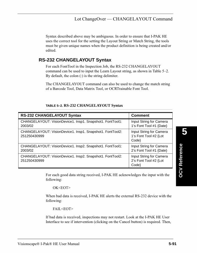
Lot ChangeOver — CHANGELAYOUT Command
OC
V R
efer
ence
5
Syntax described above may be ambiguous. In order to ensure that I-PAK HE uses the correct tool for the setting the Layout String or Match String, the tools must be given unique names when the product definition is being created and/or edited.
RS-232 CHANGELAYOUT SyntaxFor each FontTool in the Inspection Job, the RS-232 CHANGELAYOUT command can be used to input the Learn Layout string, as shown in Table 5–2. By default, the colon (:) is the string delimiter.
The CHANGELAYOUT command can also be used to change the match string of a Barcode Tool, Data Matrix Tool, or OCRTrainable Font Tool.
For each good data string received, I-PAK HE acknowledges the input with the following:
OK<EOT>
When bad data is received, I-PAK HE alerts the external RS-232 device with the following:
FAIL<EOT>
If bad data is received, inspections may not restart. Look at the I-PAK HE User Interface to see if intervention (clicking on the Cancel button) is required. Then,
TABLE 5–2. RS-232 CHANGELAYOUT Syntax
RS-232 CHANGELAYOUT Syntax Comment
CHANGELAYOUT: VisionDevice1. Insp1. Snapshot1. FontTool1: 2003/02
Input String for Camera 1’s Font Tool #1 {Date}
CHANGELAYOUT: VisionDevice1. Insp1. Snapshot1. FontTool2: 251250430999
Input String for Camera 1’s Font Tool #2 {Lot Code}
CHANGELAYOUT: VisionDevice1. Insp2. Snapshot1. FontTool1: 2003/02
Input String for Camera 2’s Font Tool #1 {Date}
CHANGELAYOUT: VisionDevice1. Insp2. Snapshot1. FontTool2: 251250430999
Input String for Camera 2’s Font Tool #2 {Lot Code}
Visionscape® I-Pak® HE User Manual 5-91
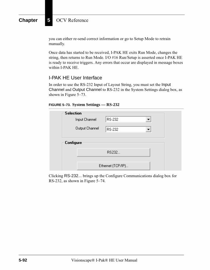
Chapter 5 OCV Reference
you can either re-send correct information or go to Setup Mode to retrain manually.
Once data has started to be received, I-PAK HE exits Run Mode, changes the string, then returns to Run Mode. I/O #16 Run/Setup is asserted once I-PAK HE is ready to receive triggers. Any errors that occur are displayed in message boxes within I-PAK HE.
I-PAK HE User InterfaceIn order to use the RS-232 Input of Layout String, you must set the Input Channel and Output Channel to RS-232 in the System Settings dialog box, as shown in Figure 5–73.
FIGURE 5–73. System Settings — RS-232
Clicking RS-232... brings up the Configure Communications dialog box for RS-232, as shown in Figure 5–74.
5-92 Visionscape® I-Pak® HE User Manual

Lot ChangeOver — CHANGELAYOUT Command
OC
V R
efer
ence
5
FIGURE 5–74. System Settings — RS-232
• If the selected RS-232 protocol is “I-PAK HE Enclosure Standard” (Figure 5–74), RS-232 communications are accomplished through COM Port 1 of I-PAK HE. With this protocol, the default RS-232 setting for this COM Port 1 are:
– Baud Rate — 9600
– Parity — None
– Data Bits — 8
– Stop Bits — 1
These settings may be adjusted to properly configure the communications with the host device.
• If the selected RS-232 protocol is “I-PAK HE Selectable Main Port” (Figure 5–75), as shown in Figure 5–75, you can select the COM Port used by I-PAK HE for RS-232 communications. Then, the RS-232 settings for the
Visionscape® I-Pak® HE User Manual 5-93
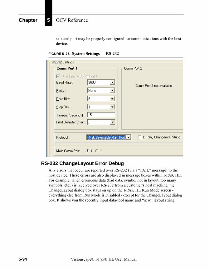
Chapter 5 OCV Reference
selected port may be properly configured for communications with the host device.
FIGURE 5–75. System Settings — RS-232
RS-232 ChangeLayout Error DebugAny errors that occur are reported over RS-232 (via a “FAIL” message) to the host device. These errors are also displayed in message boxes within I-PAK HE. For example, when erroneous data (bad data, symbol not in layout, too many symbols, etc.,) is received over RS-232 from a customer's host machine, the ChangeLayout dialog box stays on up on the I-PAK HE Run Mode screen - everything else from Run Mode is Disabled - except for the ChangeLayout dialog box. It shows you the recently input data-tool name and “new” layout string.
5-94 Visionscape® I-Pak® HE User Manual

Lot ChangeOver — CHANGELAYOUT Command
OC
V R
efer
ence
5
FIGURE 5–76. ChangeLayout RS-232 Error Status: Run Mode
FIGURE 5–77. ChangeLayout RS-232 Error Details
You MUST take action by clicking the Cancel button before I-PAK HE will “resume”. In this bad data sent state, I-PAK HE is declared “off-line”, the error message is displayed along with the exact data input and the tools.
Visionscape® I-Pak® HE User Manual 5-95
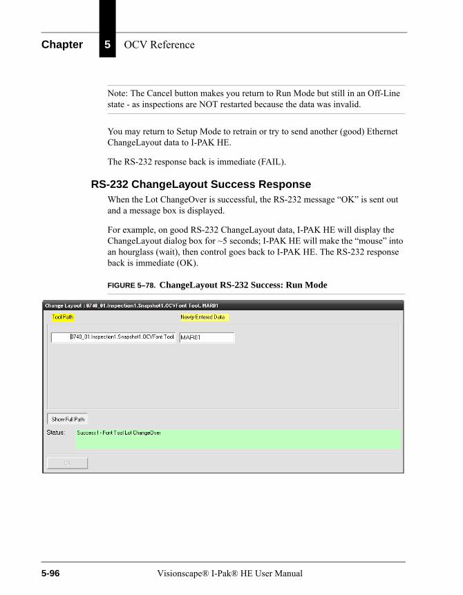
Chapter 5 OCV Reference
Note: The Cancel button makes you return to Run Mode but still in an Off-Line state - as inspections are NOT restarted because the data was invalid.
You may return to Setup Mode to retrain or try to send another (good) Ethernet ChangeLayout data to I-PAK HE.
The RS-232 response back is immediate (FAIL).
RS-232 ChangeLayout Success ResponseWhen the Lot ChangeOver is successful, the RS-232 message “OK” is sent out and a message box is displayed.
For example, on good RS-232 ChangeLayout data, I-PAK HE will display the ChangeLayout dialog box for ~5 seconds; I-PAK HE will make the “mouse” into an hourglass (wait), then control goes back to I-PAK HE. The RS-232 response back is immediate (OK).
FIGURE 5–78. ChangeLayout RS-232 Success: Run Mode
5-96 Visionscape® I-Pak® HE User Manual
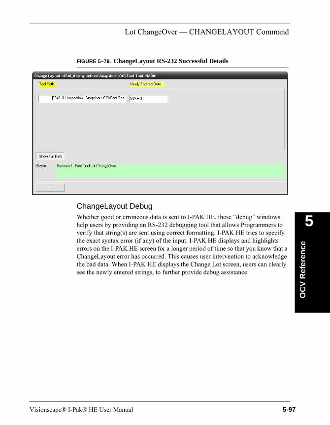
Lot ChangeOver — CHANGELAYOUT Command
OC
V R
efer
ence
5
FIGURE 5–79. ChangeLayout RS-232 Successful Details
ChangeLayout DebugWhether good or erroneous data is sent to I-PAK HE, these “debug” windows help users by providing an RS-232 debugging tool that allows Programmers to verify that string(s) are sent using correct formatting. I-PAK HE tries to specify the exact syntax error (if any) of the input. I-PAK HE displays and highlights errors on the I-PAK HE screen for a longer period of time so that you know that a ChangeLayout error has occurred. This causes user intervention to acknowledge the bad data. When I-PAK HE displays the Change Lot screen, users can clearly see the newly entered strings, to further provide debug assistance.
Visionscape® I-Pak® HE User Manual 5-97
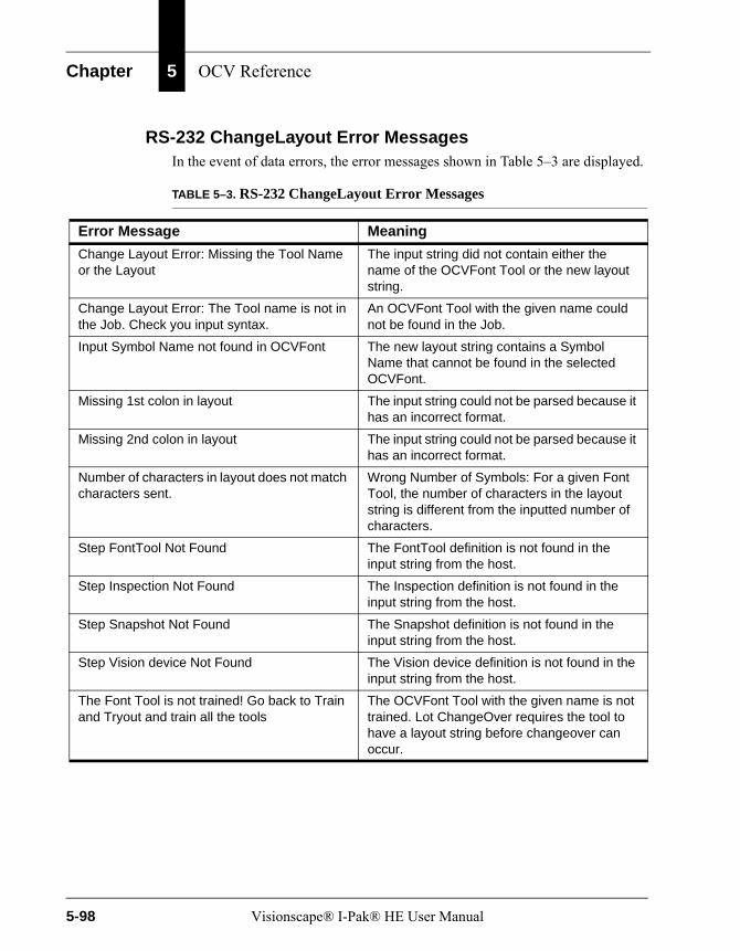
Chapter 5 OCV Reference
RS-232 ChangeLayout Error MessagesIn the event of data errors, the error messages shown in Table 5–3 are displayed.
TABLE 5–3. RS-232 ChangeLayout Error Messages
Error Message Meaning
Change Layout Error: Missing the Tool Name or the Layout
The input string did not contain either the name of the OCVFont Tool or the new layout string.
Change Layout Error: The Tool name is not in the Job. Check you input syntax.
An OCVFont Tool with the given name could not be found in the Job.
Input Symbol Name not found in OCVFont The new layout string contains a Symbol Name that cannot be found in the selected OCVFont.
Missing 1st colon in layout The input string could not be parsed because it has an incorrect format.
Missing 2nd colon in layout The input string could not be parsed because it has an incorrect format.
Number of characters in layout does not match characters sent.
Wrong Number of Symbols: For a given Font Tool, the number of characters in the layout string is different from the inputted number of characters.
Step FontTool Not Found The FontTool definition is not found in the input string from the host.
Step Inspection Not Found The Inspection definition is not found in the input string from the host.
Step Snapshot Not Found The Snapshot definition is not found in the input string from the host.
Step Vision device Not Found The Vision device definition is not found in the input string from the host.
The Font Tool is not trained! Go back to Train and Tryout and train all the tools
The OCVFont Tool with the given name is not trained. Lot ChangeOver requires the tool to have a layout string before changeover can occur.
5-98 Visionscape® I-Pak® HE User Manual
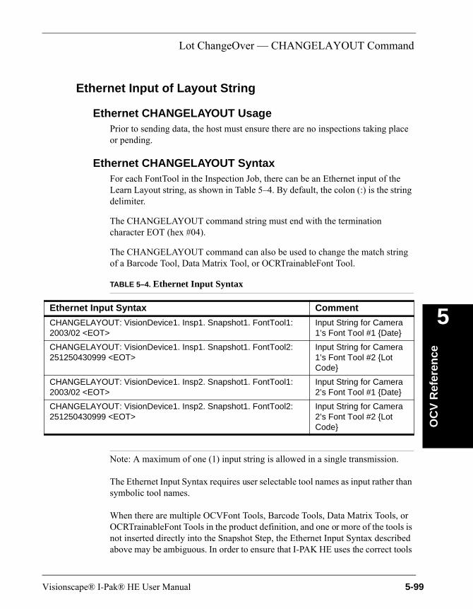
Lot ChangeOver — CHANGELAYOUT Command
OC
V R
efer
ence
5
Ethernet Input of Layout String
Ethernet CHANGELAYOUT UsagePrior to sending data, the host must ensure there are no inspections taking place or pending.
Ethernet CHANGELAYOUT SyntaxFor each FontTool in the Inspection Job, there can be an Ethernet input of the Learn Layout string, as shown in Table 5–4. By default, the colon (:) is the string delimiter.
The CHANGELAYOUT command string must end with the termination character EOT (hex #04).
The CHANGELAYOUT command can also be used to change the match string of a Barcode Tool, Data Matrix Tool, or OCRTrainableFont Tool.
Note: A maximum of one (1) input string is allowed in a single transmission.
The Ethernet Input Syntax requires user selectable tool names as input rather than symbolic tool names.
When there are multiple OCVFont Tools, Barcode Tools, Data Matrix Tools, or OCRTrainableFont Tools in the product definition, and one or more of the tools is not inserted directly into the Snapshot Step, the Ethernet Input Syntax described above may be ambiguous. In order to ensure that I-PAK HE uses the correct tools
TABLE 5–4. Ethernet Input Syntax
Ethernet Input Syntax Comment
CHANGELAYOUT: VisionDevice1. Insp1. Snapshot1. FontTool1: 2003/02 <EOT>
Input String for Camera 1’s Font Tool #1 {Date}
CHANGELAYOUT: VisionDevice1. Insp1. Snapshot1. FontTool2: 251250430999 <EOT>
Input String for Camera 1’s Font Tool #2 {Lot Code}
CHANGELAYOUT: VisionDevice1. Insp2. Snapshot1. FontTool1: 2003/02 <EOT>
Input String for Camera 2’s Font Tool #1 {Date}
CHANGELAYOUT: VisionDevice1. Insp2. Snapshot1. FontTool2: 251250430999 <EOT>
Input String for Camera 2’s Font Tool #2 {Lot Code}
Visionscape® I-Pak® HE User Manual 5-99
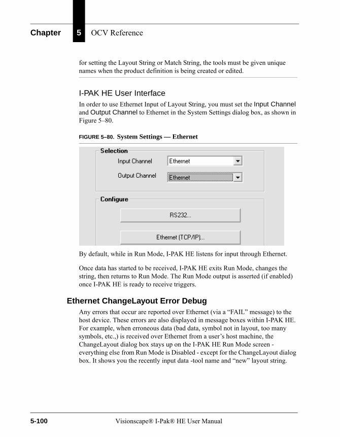
Chapter 5 OCV Reference
for setting the Layout String or Match String, the tools must be given unique names when the product definition is being created or edited.
I-PAK HE User InterfaceIn order to use Ethernet Input of Layout String, you must set the Input Channel and Output Channel to Ethernet in the System Settings dialog box, as shown in Figure 5–80.
FIGURE 5–80. System Settings — Ethernet
By default, while in Run Mode, I-PAK HE listens for input through Ethernet.
Once data has started to be received, I-PAK HE exits Run Mode, changes the string, then returns to Run Mode. The Run Mode output is asserted (if enabled) once I-PAK HE is ready to receive triggers.
Ethernet ChangeLayout Error DebugAny errors that occur are reported over Ethernet (via a “FAIL” message) to the host device. These errors are also displayed in message boxes within I-PAK HE. For example, when erroneous data (bad data, symbol not in layout, too many symbols, etc.,) is received over Ethernet from a user’s host machine, the ChangeLayout dialog box stays up on the I-PAK HE Run Mode screen - everything else from Run Mode is Disabled - except for the ChangeLayout dialog box. It shows you the recently input data -tool name and “new” layout string.
5-100 Visionscape® I-Pak® HE User Manual
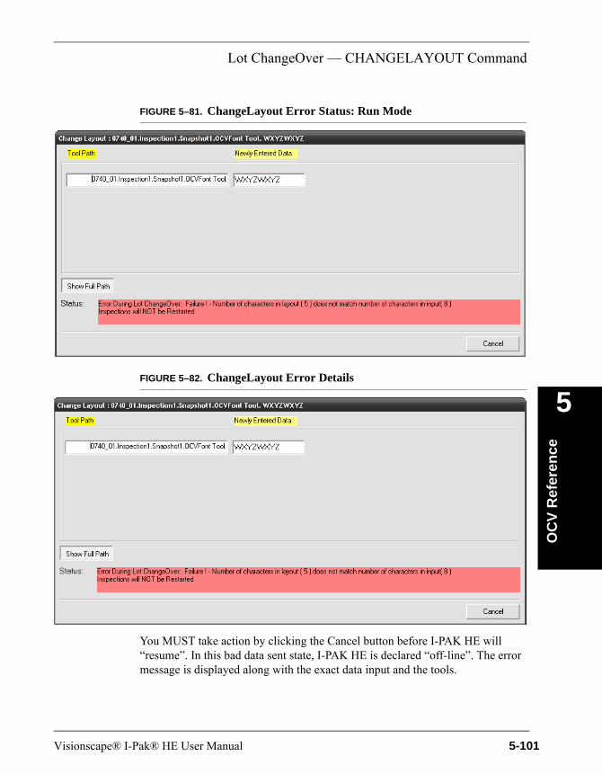
Lot ChangeOver — CHANGELAYOUT Command
OC
V R
efer
ence
5
FIGURE 5–81. ChangeLayout Error Status: Run Mode
FIGURE 5–82. ChangeLayout Error Details
You MUST take action by clicking the Cancel button before I-PAK HE will “resume”. In this bad data sent state, I-PAK HE is declared “off-line”. The error message is displayed along with the exact data input and the tools.
Visionscape® I-Pak® HE User Manual 5-101
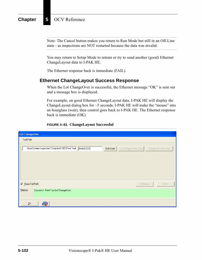
Chapter 5 OCV Reference
Note: The Cancel button makes you return to Run Mode but still in an Off-Line state - as inspections are NOT restarted because the data was invalid.
You may return to Setup Mode to retrain or try to send another (good) Ethernet ChangeLayout data to I-PAK HE.
The Ethernet response back is immediate (FAIL).
Ethernet ChangeLayout Success ResponseWhen the Lot ChangeOver is successful, the Ethernet message “OK” is sent out and a message box is displayed.
For example, on good Ethernet ChangeLayout data, I-PAK HE will display the ChangeLayout dialog box for ~5 seconds; I-PAK HE will make the “mouse” into an hourglass (wait), then control goes back to I-PAK HE. The Ethernet response back is immediate (OK).
FIGURE 5–83. ChangeLayout Successful
5-102 Visionscape® I-Pak® HE User Manual
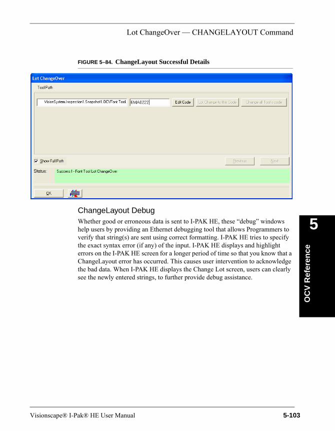
Lot ChangeOver — CHANGELAYOUT Command
OC
V R
efer
ence
5
FIGURE 5–84. ChangeLayout Successful Details
ChangeLayout DebugWhether good or erroneous data is sent to I-PAK HE, these “debug” windows help users by providing an Ethernet debugging tool that allows Programmers to verify that string(s) are sent using correct formatting. I-PAK HE tries to specify the exact syntax error (if any) of the input. I-PAK HE displays and highlight errors on the I-PAK HE screen for a longer period of time so that you know that a ChangeLayout error has occurred. This causes user intervention to acknowledge the bad data. When I-PAK HE displays the Change Lot screen, users can clearly see the newly entered strings, to further provide debug assistance.
Visionscape® I-Pak® HE User Manual 5-103
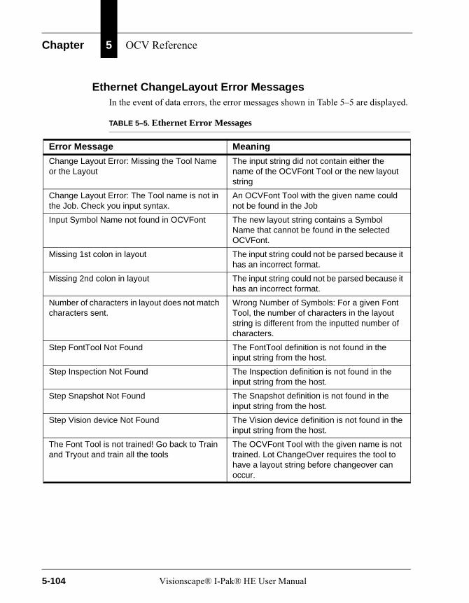
Chapter 5 OCV Reference
Ethernet ChangeLayout Error MessagesIn the event of data errors, the error messages shown in Table 5–5 are displayed.
TABLE 5–5. Ethernet Error Messages
Error Message Meaning
Change Layout Error: Missing the Tool Name or the Layout
The input string did not contain either the name of the OCVFont Tool or the new layout string
Change Layout Error: The Tool name is not in the Job. Check you input syntax.
An OCVFont Tool with the given name could not be found in the Job
Input Symbol Name not found in OCVFont The new layout string contains a Symbol Name that cannot be found in the selected OCVFont.
Missing 1st colon in layout The input string could not be parsed because it has an incorrect format.
Missing 2nd colon in layout The input string could not be parsed because it has an incorrect format.
Number of characters in layout does not match characters sent.
Wrong Number of Symbols: For a given Font Tool, the number of characters in the layout string is different from the inputted number of characters.
Step FontTool Not Found The FontTool definition is not found in the input string from the host.
Step Inspection Not Found The Inspection definition is not found in the input string from the host.
Step Snapshot Not Found The Snapshot definition is not found in the input string from the host.
Step Vision device Not Found The Vision device definition is not found in the input string from the host.
The Font Tool is not trained! Go back to Train and Tryout and train all the tools
The OCVFont Tool with the given name is not trained. Lot ChangeOver requires the tool to have a layout string before changeover can occur.
5-104 Visionscape® I-Pak® HE User Manual
OCV Tips
OC
V R
efer
ence
5
OCV TipsThe OCV tools found in I-PAK HE have many settings and adjustments to allow for maximum flexibility. However, most applications require attention to only a few of these settings and adjustments.
OCVFont
• ID Test Determination Pct — Lowering the default value of 85% to 80% or 75% causes more characters to be flagged as similar.
Layout Step
• Automatic Segmentation — By default, this property is off, which allows the font library creation box to be sized manually around each character as it is entered into the library. I-PAK HE is designed such that you perform this individual training of characters to activate runtime ID checking of special characters like O, 0, B, 8, D, etc. ID checking requires that these symbol boxes be the same size.
Note: Whenever possible, use the same size box to train all font library characters.
You can enable the automatic segmentation property, and I-PAK HE automatically locates and places a box around all characters in the FOV.
DefaultSymbol
• Final Residue Limit — Increasing the default value of 15% to a higher number allows characters to vary more and still be accepted. Increasing this value has a gradual effect.
• Max Flaw Size — Increasing the default value of 1 pixel to a higher value allows characters to vary more and still be accepted. Increasing this value has a rapid effect. This number should not be set greater than 2.
OCVRuntimeToolThe OCVRuntimeTool is the vision step that actually performs the inspection of a code.
Visionscape® I-Pak® HE User Manual 5-105
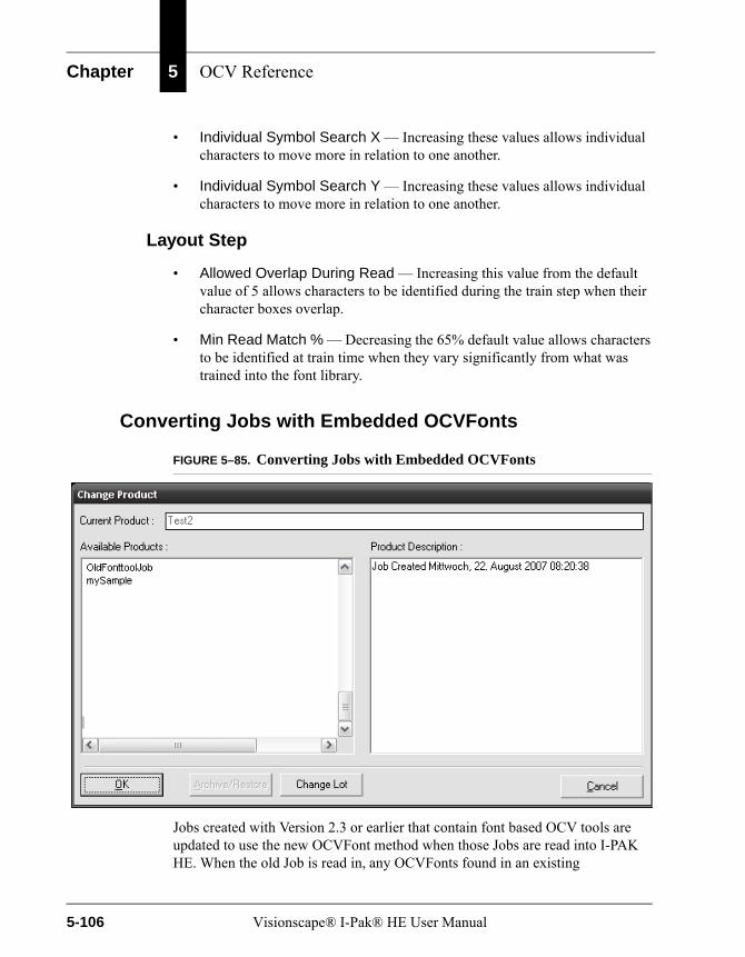
Chapter 5 OCV Reference
• Individual Symbol Search X — Increasing these values allows individual characters to move more in relation to one another.
• Individual Symbol Search Y — Increasing these values allows individual characters to move more in relation to one another.
Layout Step
• Allowed Overlap During Read — Increasing this value from the default value of 5 allows characters to be identified during the train step when their character boxes overlap.
• Min Read Match % — Decreasing the 65% default value allows characters to be identified at train time when they vary significantly from what was trained into the font library.
Converting Jobs with Embedded OCVFonts
FIGURE 5–85. Converting Jobs with Embedded OCVFonts
Jobs created with Version 2.3 or earlier that contain font based OCV tools are updated to use the new OCVFont method when those Jobs are read into I-PAK HE. When the old Job is read in, any OCVFonts found in an existing
5-106 Visionscape® I-Pak® HE User Manual
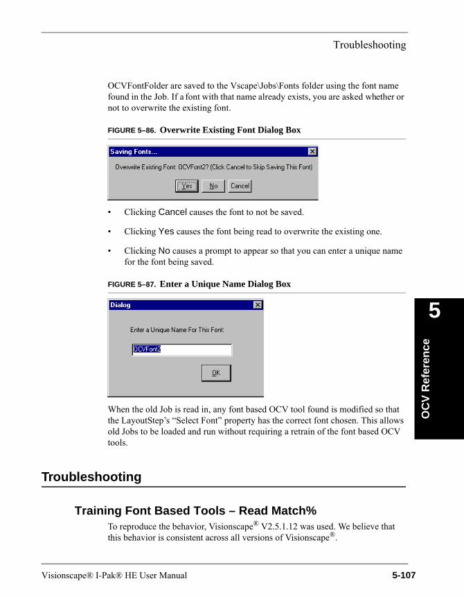
Troubleshooting
OC
V R
efer
ence
5
OCVFontFolder are saved to the Vscape\Jobs\Fonts folder using the font name found in the Job. If a font with that name already exists, you are asked whether or not to overwrite the existing font.
FIGURE 5–86. Overwrite Existing Font Dialog Box
• Clicking Cancel causes the font to not be saved.
• Clicking Yes causes the font being read to overwrite the existing one.
• Clicking No causes a prompt to appear so that you can enter a unique name for the font being saved.
FIGURE 5–87. Enter a Unique Name Dialog Box
When the old Job is read in, any font based OCV tool found is modified so that the LayoutStep’s “Select Font” property has the correct font chosen. This allows old Jobs to be loaded and run without requiring a retrain of the font based OCV tools.
Troubleshooting
Training Font Based Tools – Read Match%To reproduce the behavior, Visionscape® V2.5.1.12 was used. We believe that this behavior is consistent across all versions of Visionscape®.
Visionscape® I-Pak® HE User Manual 5-107
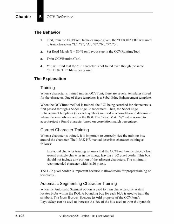
Chapter 5 OCV Reference
The Behavior
1. First, train the OCVFont. In the example given, the “TEXT02.TIF” was used to train characters “L”, “2”, “A”, “0”, “6”, “9”, “3”.
2. Set Read Match % = 80 % on Layout step in the OCVRuntimeTool.
3. Train OCVRuntimeTool.
4. You will find that the “L” character is not found even though the same “TEXT02.TIF” file is being used.
The Explanation
TrainingWhen a character is trained into an OCVFont, there are several templates stored for the character. One of these templates is a Sobel Edge Enhancement template.
When the OCVRuntimeTool is trained, the ROI being searched for characters is first passed through a Sobel Edge Enhancement. Then, the Sobel Edge Enhancement templates (for each symbol) are used in a correlation to determine where the symbols are within the ROI. The “Read Match%” value is used to accept/reject a found character based on correlation match percentage.
Correct Character TrainingWhen a character is trained, it is important to correctly size the training box around the character. The I-PAK HE manual describes character training as follows:
Individual character training requires that the OCVFont box be placed close around a single character in the image, leaving a 1-2 pixel border. This box should not include any portion of the adjacent characters. The minimum recommended character width is 20 pixels.
The 1 - 2 pixel border is important because it allows room for proper training of templates.
Automatic Segmenting Character TrainingWhen the Automatic Segment option is used to train characters, the system locates blobs within the ROI. A bounding box for each blob is used to train the symbols. The Num Border Spaces to Add property of the OCVFont’s LayoutStep can be used to increase the size of the box used to train the symbols.
5-108 Visionscape® I-Pak® HE User Manual
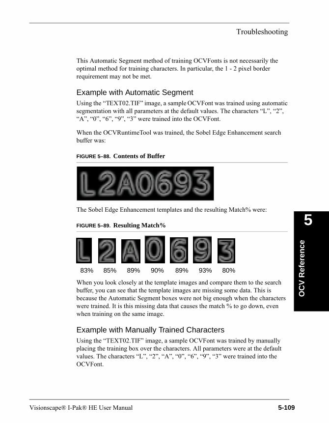
Troubleshooting
OC
V R
efer
ence
5
This Automatic Segment method of training OCVFonts is not necessarily the optimal method for training characters. In particular, the 1 - 2 pixel border requirement may not be met.
Example with Automatic SegmentUsing the “TEXT02.TIF” image, a sample OCVFont was trained using automatic segmentation with all parameters at the default values. The characters “L”, “2”, “A”, “0”, “6”, “9”, “3” were trained into the OCVFont.
When the OCVRuntimeTool was trained, the Sobel Edge Enhancement search buffer was:
FIGURE 5–88. Contents of Buffer
The Sobel Edge Enhancement templates and the resulting Match% were:
FIGURE 5–89. Resulting Match%
When you look closely at the template images and compare them to the search buffer, you can see that the template images are missing some data. This is because the Automatic Segment boxes were not big enough when the characters were trained. It is this missing data that causes the match % to go down, even when training on the same image.
Example with Manually Trained CharactersUsing the “TEXT02.TIF” image, a sample OCVFont was trained by manually placing the training box over the characters. All parameters were at the default values. The characters “L”, “2”, “A”, “0”, “6”, “9”, “3” were trained into the OCVFont.
83% 85% 89% 90% 89% 93% 80%
Visionscape® I-Pak® HE User Manual 5-109

Chapter 5 OCV Reference
When the OCVRuntimeTool was trained, the Sobel Edge Enhancement search buffer was (the same as above example):
FIGURE 5–90. Contents of Buffer
The Sobel Edge Enhancement templates and the resulting Match% were:
FIGURE 5–91. Resulting Match%
Comparing these templates to the search buffer, you can see that the template characters more closely resemble those in the search area as reflected by the Match % values. By manually positioning the training boxes, we were able to ensure that the proper amount of spacing was available for template training.
Conclusions
• Microscan currently recommends that OCVFont training be performed using manual placement of the training box. This is because the training box should be the same size over symbols that are similar in order for the Runtime ID Checking algorithms to work optimally. The Automatic Segmentation cannot assure that the boxes around similar characters are the same size. Using manual placement with the correct 1 - 2 pixel border will also help prevent the behavior described in this document.
• The Auto Segmentation training of OCVFonts is useful for quick demos or to quickly prove out an inspection scenario. While the behavior described may cause confusion at train time when using a frozen image, the Runtime inspections remain intact. The runtime inspections do not use the Sobel Edge Enhancement templates.
99% 95% 98% 98% 99% 99% 99%
5-110 Visionscape® I-Pak® HE User Manual

Troubleshooting
OC
V R
efer
ence
5
• The default value for Num of Border Spaces to Add may need to be increased to 2. This would give the Automatic Segmentation characters more border space with which to train the characters. While this would probably help with the Read Match%, increasing the border space may cause some symbol overlap in cases where the symbols are close together. Microscan recommends manual training of the OCVFont.
Visionscape® I-Pak® HE User Manual 5-111

Chapter 5 OCV Reference
5-112 Visionscape® I-Pak® HE User Manual

6
Set
up
Mo
de
Ref
eren
ce
6
CHAPTER 6 Setup Mode Reference
This chapter presents the Visionscape® I-PAK® HE Setup Mode functionality, and describes the following:
• “Setup Mode Menus” on page 6-3
• “Change Product” on page 6-10
• “Train and Tryout” on page 6-17
• “Statistics & Data” on page 6-32
• “Advanced Settings” on page 6-42
• “Run Mode” on page 6-98
• “Troubleshooting” on page 6-98
OverviewYou enter Setup Mode by entering correctly either the Programmer’s default password (0101) or the Supervisor’s default password (1010) from Run Mode. In Setup Mode, you create and program Jobs, retrain tools, and review end-of-batch results. The Setup Mode window is displayed in Figure 6–1.
Visionscape® I-Pak® HE User Manual 6-1
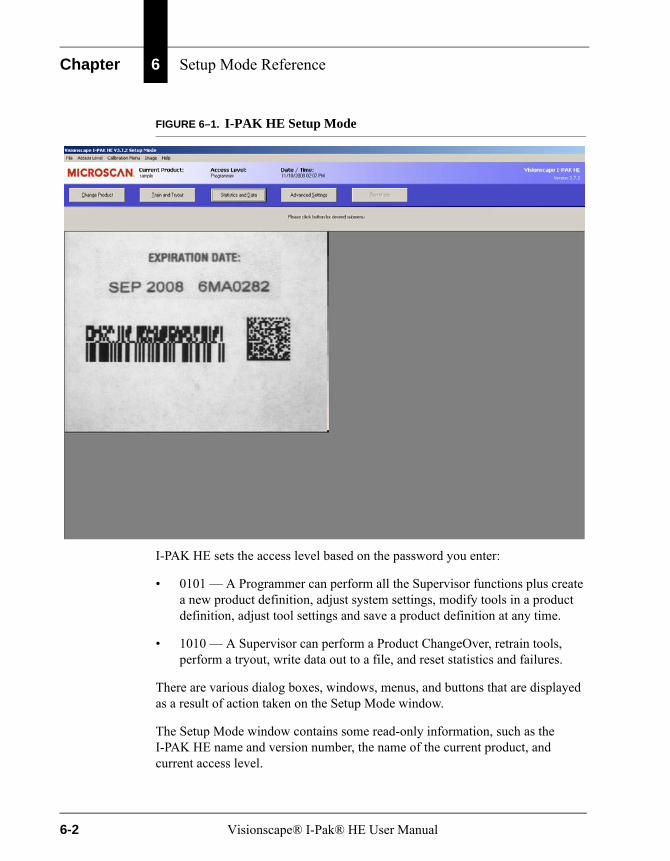
Chapter 6 Setup Mode Reference
FIGURE 6–1. I-PAK HE Setup Mode
I-PAK HE sets the access level based on the password you enter:
• 0101 — A Programmer can perform all the Supervisor functions plus create a new product definition, adjust system settings, modify tools in a product definition, adjust tool settings and save a product definition at any time.
• 1010 — A Supervisor can perform a Product ChangeOver, retrain tools, perform a tryout, write data out to a file, and reset statistics and failures.
There are various dialog boxes, windows, menus, and buttons that are displayed as a result of action taken on the Setup Mode window.
The Setup Mode window contains some read-only information, such as the I-PAK HE name and version number, the name of the current product, and current access level.
6-2 Visionscape® I-Pak® HE User Manual
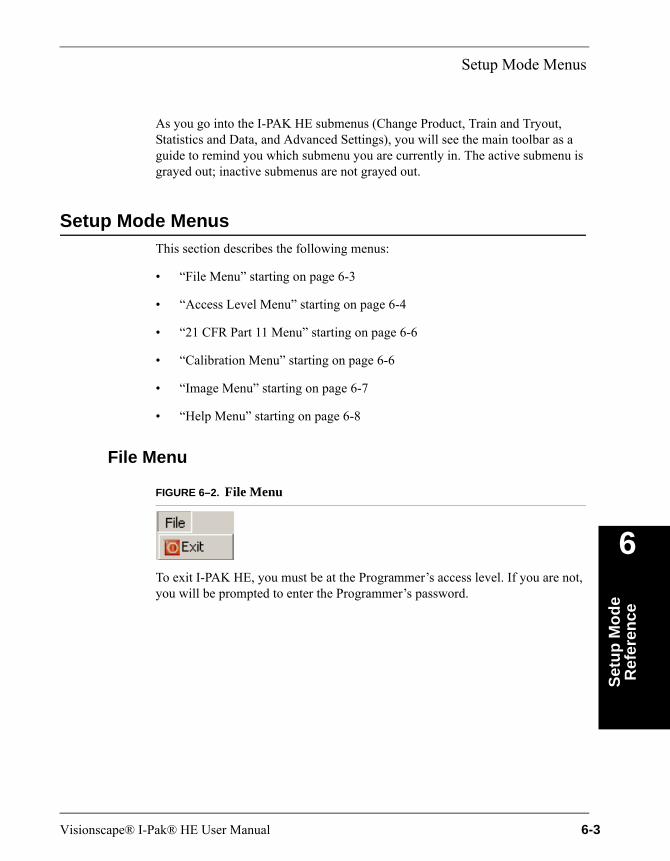
Setup Mode Menus
Set
up
Mo
de
Ref
eren
ce
6
As you go into the I-PAK HE submenus (Change Product, Train and Tryout, Statistics and Data, and Advanced Settings), you will see the main toolbar as a guide to remind you which submenu you are currently in. The active submenu is grayed out; inactive submenus are not grayed out.
Setup Mode MenusThis section describes the following menus:
• “File Menu” starting on page 6-3
• “Access Level Menu” starting on page 6-4
• “21 CFR Part 11 Menu” starting on page 6-6
• “Calibration Menu” starting on page 6-6
• “Image Menu” starting on page 6-7
• “Help Menu” starting on page 6-8
File Menu
FIGURE 6–2. File Menu
To exit I-PAK HE, you must be at the Programmer’s access level. If you are not, you will be prompted to enter the Programmer’s password.
Visionscape® I-Pak® HE User Manual 6-3
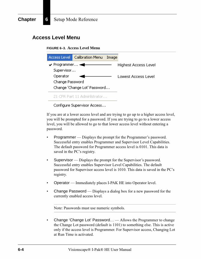
Chapter 6 Setup Mode Reference
Access Level Menu
FIGURE 6–3. Access Level Menu
If you are at a lower access level and are trying to go up to a higher access level, you will be prompted for a password. If you are trying to go to a lower access level, you will be allowed to go to that lower access level without entering a password.
• Programmer — Displays the prompt for the Programmer’s password. Successful entry enables Programmer and Supervisor Level Capabilities. The default password for Programmer access level is 0101. This data is saved in the PC’s registry.
• Supervisor — Displays the prompt for the Supervisor’s password. Successful entry enables Supervisor Level Capabilities. The default password for Supervisor access level is 1010. This data is saved in the PC’s registry.
• Operator — Immediately places I-PAK HE into Operator level.
• Change Password — Displays a dialog box for a new password for the currently enabled access level.
Note: Passwords must use numeric symbols.
• Change ‘Change Lot’ Password… — Allows the Programmer to change the Change Lot password (default is 1101) to something else. This is active only if the access level is Programmer. For Supervisor access, Changing Lot at Run Time is activated.
Highest Access Level
Lowest Access Level
6-4 Visionscape® I-Pak® HE User Manual
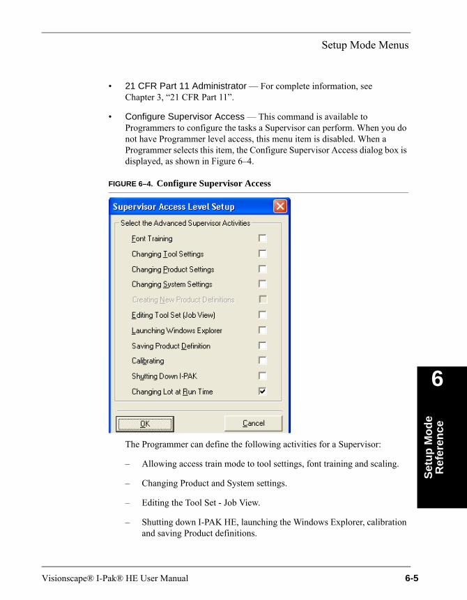
Setup Mode Menus
Set
up
Mo
de
Ref
eren
ce
6
• 21 CFR Part 11 Administrator — For complete information, see Chapter 3, “21 CFR Part 11”.
• Configure Supervisor Access — This command is available to Programmers to configure the tasks a Supervisor can perform. When you do not have Programmer level access, this menu item is disabled. When a Programmer selects this item, the Configure Supervisor Access dialog box is displayed, as shown in Figure 6–4.
FIGURE 6–4. Configure Supervisor Access
The Programmer can define the following activities for a Supervisor:
– Allowing access train mode to tool settings, font training and scaling.
– Changing Product and System settings.
– Editing the Tool Set - Job View.
– Shutting down I-PAK HE, launching the Windows Explorer, calibration and saving Product definitions.
Visionscape® I-Pak® HE User Manual 6-5
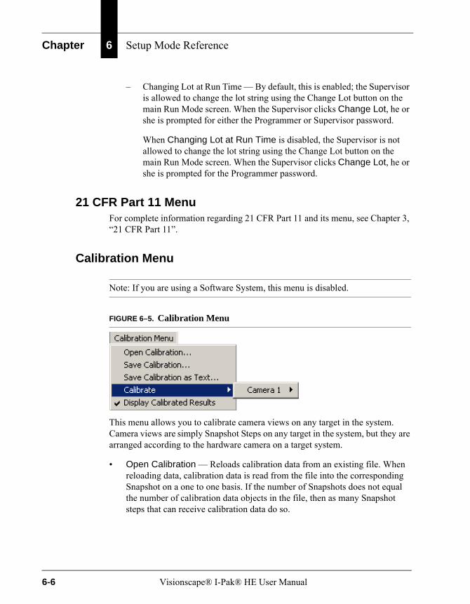
Chapter 6 Setup Mode Reference
– Changing Lot at Run Time — By default, this is enabled; the Supervisor is allowed to change the lot string using the Change Lot button on the main Run Mode screen. When the Supervisor clicks Change Lot, he or she is prompted for either the Programmer or Supervisor password.
When Changing Lot at Run Time is disabled, the Supervisor is not allowed to change the lot string using the Change Lot button on the main Run Mode screen. When the Supervisor clicks Change Lot, he or she is prompted for the Programmer password.
21 CFR Part 11 MenuFor complete information regarding 21 CFR Part 11 and its menu, see Chapter 3, “21 CFR Part 11”.
Calibration Menu
Note: If you are using a Software System, this menu is disabled.
FIGURE 6–5. Calibration Menu
This menu allows you to calibrate camera views on any target in the system. Camera views are simply Snapshot Steps on any target in the system, but they are arranged according to the hardware camera on a target system.
• Open Calibration — Reloads calibration data from an existing file. When reloading data, calibration data is read from the file into the corresponding Snapshot on a one to one basis. If the number of Snapshots does not equal the number of calibration data objects in the file, then as many Snapshot steps that can receive calibration data do so.
6-6 Visionscape® I-Pak® HE User Manual

Setup Mode Menus
Set
up
Mo
de
Ref
eren
ce
6
• Save Calibration — Saves calibration data to a separate file. When saving data, calibration data from each Snapshot Step in every target is saved in one file with a .cal extension.
• Save Calibration as Text — Writes the entire calibration World tree to disk as a text file.
• Calibrate — Starts the calibration process on Snapshot x of Camera y.
• Display Calibrated Results — Enables or disables the display of the calibrated measurement results at Runtime in calibrated units.
Different Snapshot Steps, which use the same Smart Camera, are considered different views of the camera and can be calibrated individually or as a group. The different camera menus under “Calibrate” list the names of each Snapshot in the corresponding target. When you click one of these menus, the Calibration Wizard from the Calibration Manager control is displayed, and you can calibrate the camera view.
When the Smart Camera is calibrated, its data is saved in the .avp file. Open Calibration and Save Calibration are a means to extract the calibration data into a file and reload it into a different program.
For complete information regarding Calibration, see Chapter 2 of the Visionscape® Tools Reference (on your CD in PDF format).
Image Menu
FIGURE 6–6. Image Menu
• Open — When Open is selected, the Open Image dialog box is displayed. From here, you can open a previously saved I-PAK HE image. This may be useful for retraining tools or debugging an application with a frozen image.
• Save — When Save is selected, the Save Image dialog box is displayed. From here, you can save an I-PAK HE image to your hard drive. This may be useful in storing a golden training image or for debugging purposes.
Visionscape® I-Pak® HE User Manual 6-7

Chapter 6 Setup Mode Reference
Help Menu
FIGURE 6–7. Help Menu
• I/O Debug... — This graphical representation is available only in Setup Mode and only at the Programmer access level. When I/O Debug... is selected, the I-PAK HE I/O Debug diagnostic tool is displayed, as shown in Figure 6–8.
FIGURE 6–8. I/O Debug Diagnostic Display
A Programmer can access an I/O Diagnostic tool to set and view the state of physical and virtual I/O. Once the I/O Diagnostic tool is displayed, the Programmer must connect to a HawkEye 1600T Smart Camera by selecting it from the drop-down list, and clicking on the Connect button.
The top portion of the window displays the physical I/O; the bottom portion displays the virtual I/O. Inputs are indicated as yellow buttons. Where
Connect
6-8 Visionscape® I-Pak® HE User Manual
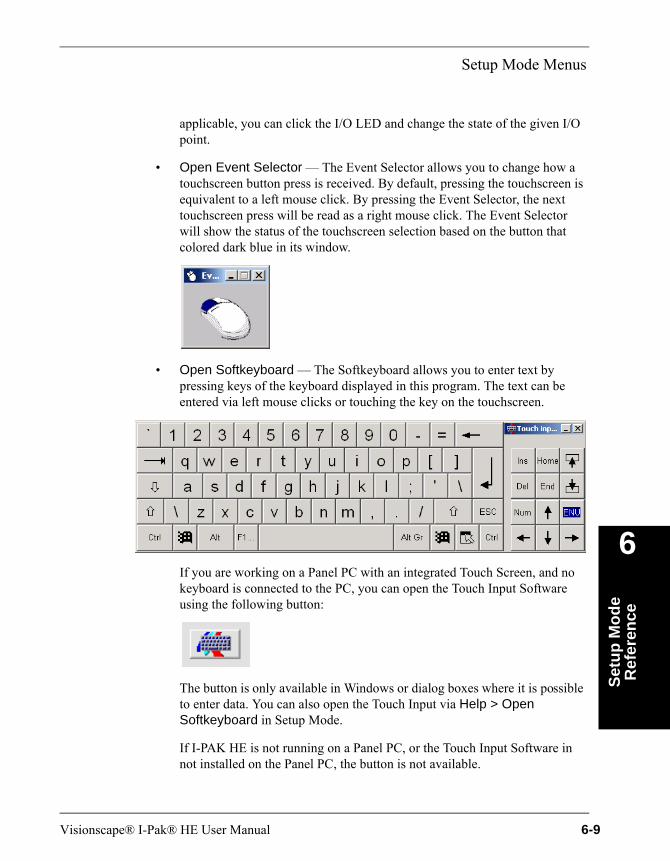
Setup Mode Menus
Set
up
Mo
de
Ref
eren
ce
6
applicable, you can click the I/O LED and change the state of the given I/O point.
• Open Event Selector — The Event Selector allows you to change how a touchscreen button press is received. By default, pressing the touchscreen is equivalent to a left mouse click. By pressing the Event Selector, the next touchscreen press will be read as a right mouse click. The Event Selector will show the status of the touchscreen selection based on the button that colored dark blue in its window.
• Open Softkeyboard — The Softkeyboard allows you to enter text by pressing keys of the keyboard displayed in this program. The text can be entered via left mouse clicks or touching the key on the touchscreen.
If you are working on a Panel PC with an integrated Touch Screen, and no keyboard is connected to the PC, you can open the Touch Input Software using the following button:
The button is only available in Windows or dialog boxes where it is possible to enter data. You can also open the Touch Input via Help > Open Softkeyboard in Setup Mode.
If I-PAK HE is not running on a Panel PC, or the Touch Input Software in not installed on the Panel PC, the button is not available.
Visionscape® I-Pak® HE User Manual 6-9
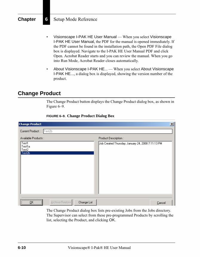
Chapter 6 Setup Mode Reference
• Visionscape I-PAK HE User Manual — When you select Visionscape I-PAK HE User Manual, the PDF for the manual is opened immediately. If the PDF cannot be found in the installation path, the Open PDF File dialog box is displayed. Navigate to the I-PAK HE User Manual PDF and click Open. Acrobat Reader starts and you can review the manual. When you go into Run Mode, Acrobat Reader closes automatically.
• About Visionscape I-PAK HE... — When you select About Visionscape I-PAK HE..., a dialog box is displayed, showing the version number of the product.
Change ProductThe Change Product button displays the Change Product dialog box, as shown in Figure 6–9.
FIGURE 6–9. Change Product Dialog Box
The Change Product dialog box lists pre-existing Jobs from the Jobs directory. The Supervisor can select from these pre-programmed Products by scrolling the list, selecting the Product, and clicking OK.
6-10 Visionscape® I-Pak® HE User Manual
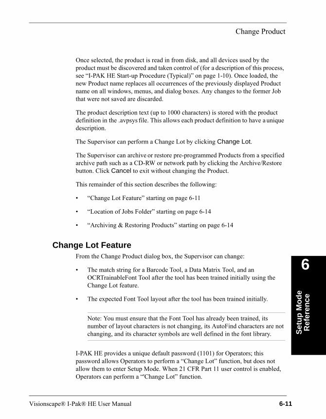
Change Product
Set
up
Mo
de
Ref
eren
ce
6
Once selected, the product is read in from disk, and all devices used by the product must be discovered and taken control of (for a description of this process, see “I-PAK HE Start-up Procedure (Typical)” on page 1-10). Once loaded, the new Product name replaces all occurrences of the previously displayed Product name on all windows, menus, and dialog boxes. Any changes to the former Job that were not saved are discarded.
The product description text (up to 1000 characters) is stored with the product definition in the .avpsys file. This allows each product definition to have a unique description.
The Supervisor can perform a Change Lot by clicking Change Lot.
The Supervisor can archive or restore pre-programmed Products from a specified archive path such as a CD-RW or network path by clicking the Archive/Restore button. Click Cancel to exit without changing the Product.
This remainder of this section describes the following:
• “Change Lot Feature” starting on page 6-11
• “Location of Jobs Folder” starting on page 6-14
• “Archiving & Restoring Products” starting on page 6-14
Change Lot FeatureFrom the Change Product dialog box, the Supervisor can change:
• The match string for a Barcode Tool, a Data Matrix Tool, and an OCRTrainableFont Tool after the tool has been trained initially using the Change Lot feature.
• The expected Font Tool layout after the tool has been trained initially.
Note: You must ensure that the Font Tool has already been trained, its number of layout characters is not changing, its AutoFind characters are not changing, and its character symbols are well defined in the font library.
I-PAK HE provides a unique default password (1101) for Operators; this password allows Operators to perform a “Change Lot” function, but does not allow them to enter Setup Mode. When 21 CFR Part 11 user control is enabled, Operators can perform a “'Change Lot” function.
Visionscape® I-Pak® HE User Manual 6-11
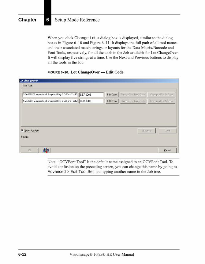
Chapter 6 Setup Mode Reference
When you click Change Lot, a dialog box is displayed, similar to the dialog boxes in Figure 6–10 and Figure 6–11. It displays the full path of all tool names and their associated match strings or layouts for the Data Matrix/Barcode and Font Tools, respectively, for all the tools in the Job available for Lot ChangeOver. It will display five strings at a time. Use the Next and Previous buttons to display all the tools in the Job.
FIGURE 6–10. Lot ChangeOver — Edit Code
Note: “OCVFont Tool” is the default name assigned to an OCVFont Tool. To avoid confusion on the preceding screen, you can change this name by going to Advanced > Edit Tool Set, and typing another name in the Job tree.
6-12 Visionscape® I-Pak® HE User Manual

Change Product
Set
up
Mo
de
Ref
eren
ce
6
FIGURE 6–11. Lot ChangeOver — Complete
If you want to change a Code, simply click Edit Code for the specific tool(s). This allows you to edit the contents of the match or layout string. This also enables the Change this Tool’s Code and the Change all Tool’s Code buttons.
When you want to just change one match or layout string at a time, edit the code and click Change this Tool’s Code. This will change the match or layout string to the contents you just specified. I-PAK HE will display an error message if the number of characters in the new string is not equal to the number of characters in the old string. I-PAK HE will display a message if any of the characters in the new string are not defined in the OCVFont used by the tool. When no errors are encountered, I-PAK HE displays a “success” message.
If a Job has multiple tools that have identical match or layout strings, you can change them all at once by editing the code for any one and then clicking Change all Tool’s Code. Then, I-PAK HE will go through the Job and change the match or layout string to the contents you just specified for all tools that had the same code.
Note: The Font Tool IGNORE character “@” and Data Matrix Tool IGNORE character “?” are allowed in this dialog box.
This feature supports up to 99 Font, Data Matrix and Barcode tools total in any one Job.
Visionscape® I-Pak® HE User Manual 6-13

Chapter 6 Setup Mode Reference
Location of Jobs FolderThe Jobs folder is created in the directory in which I-PAK HE was installed and from which you run I-PAK HE. For example, if you install the I-PAK HE software in C:\Vscape, then, when you first run I-PAK HE, it automatically creates the Jobs folder as follows:
C:\Vscape\I-Pak_HE\Jobs
Using Windows Explorer, you can back up your Job definitions to another disk or CD.
Automatic Backup of JobsI-PAK HE performs an automatic backup of the current product definition to help you recover in the event of a PC disk error. Every time that a product definition is about to be saved, an automatic copy of the Job is created in a directory called JobsBackup that is located within your Jobs directory. For example, this automatic backup directory will be C:\Vscape\I-Pak_HE\Jobs\JobsBackup.
In the event of a PC disk error, you can recover the .avp and .avpsys files for your products (minus your last edits). The file is suffixed with a -1 to further designate that these file copies are one revision behind the current product definition.
Archiving & Restoring ProductsThrough the I-PAK HE interface, you can archive and restore products from a CD-RW or any other valid path, such as a directory or across a network. I-PAK HE Job files are rather large and, typically, do not fit on a floppy. By using a CD-RW, you can archive your Jobs and restore them safely. You must set up the CD-RW software before you can use this feature (see “CD-RW Support” on page C-15).
Setting Archival PathnameIn the System Settings menu, in the Product ChangeOver Activities dialog box, you need to specify the path of the archive location. For example, when using a CDR, this path might be D:\.
Job Archive Dialog BoxWhen you go to the Product ChangeOver dialog box, you’ll notice the Archive/Restore button. Click this button to display the Job Archive dialog box, as shown in Figure 6–12.
6-14 Visionscape® I-Pak® HE User Manual
Change Product
Set
up
Mo
de
Ref
eren
ce
6
FIGURE 6–12. Job Archive Dialog Box — Archive Example
In this Job Archive dialog box, the left-hand display shows the Jobs from the current I-Pak_HE\Jobs folder, while the right-hand display shows the Jobs from the archival path. In this example, we used a CDR for the archival path.
You must ready the CD media before you can begin using it.
Note: You’ll always need to archive and restore both the .avp and .avpsys files for a product to run in I-PAK HE.
• To archive a Job from the Current Jobs folder to the Archived Jobs, click on the Job name and its associated .avpsys file from the left-hand list. Then, click Save-> to copy those files onto the archival path. In this case, it copies the files from the I-Pak_HE\Jobs directory to the CDR. To select more than one file at a time, hold the Ctrl key while clicking file names.
• To restore a Job from the Archived Jobs to the Current Jobs folder, simply click on the Job name and its associated .avpsys file from the right-hand list. Then, click on <-Restore to copy those files back to the Current Jobs folder. In this case, it will copy the files from the CDR to the I-Pak_HE\Jobs directory.
Visionscape® I-Pak® HE User Manual 6-15
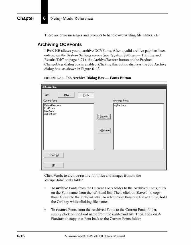
Chapter 6 Setup Mode Reference
There are error messages and prompts to handle overwriting file names, etc.
Archiving OCVFontsI-PAK HE allows you to archive OCVFonts. After a valid archive path has been entered on the System Settings screen (see “System Settings — Training and Results Tab” on page 6-71), the Archive/Restore button on the Product ChangeOver dialog box is enabled. Clicking this button displays the Job Archive dialog box, as shown in Figure 6–13.
FIGURE 6–13. Job Archive Dialog Box — Fonts Button
Click Fonts to archive/restore font files and images from/to the Vscape\Jobs\Fonts folder.
• To archive Fonts from the Current Fonts folder to the Archived Fonts, click on the Font name from the left-hand list. Then, click on Save-> to copy those files onto the archival path. To select more than one file at a time, hold the Ctrl key while clicking file names.
• To restore Fonts from the Archived Fonts to the Current Fonts folder, simply click on the Font name from the right-hand list. Then, click on <-Restore to copy that Font back to the Current Fonts folder.
6-16 Visionscape® I-Pak® HE User Manual

Train and Tryout
Set
up
Mo
de
Ref
eren
ce
6
Train and TryoutTrain and Tryout displays the Train and Tryout wizard mode window, as shown in Figure 6–14.
FIGURE 6–14. Train and Tryout Wizard Window
The Training and Tryout functions are grouped into one and utilize the same display. The Supervisor/Programmer can train, retrain, and tryout the tools from this display. The concept of wizard mode exists in this menu much like the Create a Product wizard mode.
First, you want to train your tools. AutoStep guides you through the training process.
Visionscape® I-Pak® HE User Manual 6-17

Chapter 6 Setup Mode Reference
This remainder of this section describes the following:
• “AutoStep or Wizard Training Method” starting on page 6-18
• “AutoStep Off” starting on page 6-19
• “Train and Tryout Mode” starting on page 6-19
• “Train and Tryout Toolbar” starting on page 6-19
• “Automatically Setting Tool Settings” starting on page 6-25
• “Special Training of Tools” starting on page 6-25
AutoStep or Wizard Training MethodThe AutoStep or Wizard method of training walks the Supervisor or Programmer through each step of the training sequence.
Note: The I-PAK HE interface uses the term “AutoStep” rather than “Wizard”.
By default, AutoStep training is invoked automatically when you first enter this window, but can be changed via a system setting. For more information, see AutoStep Mode On Automatically in Train and Tryout on page 6–84.
ImageThe image will display the last runtime or acquired image associated with that snapshot with the tool graphics superimposed. The Programmer/Supervisor is required to train each tool and then click Next to proceed to the next tool.
Job ViewThe data on the left-hand side of the display is your Job. As you successfully train each tool in your Job, a green check mark appears next to each tool name. With AutoStep off, you can click directly on a tool in this view for retraining, or click on its shape in the image window.
Note: Some steps like the Inspection step update its status after all of the tools in that Inspection have completed. This means that the Inspection step could display a red X until the last tool has been trained and then would change to a green check mark.
6-18 Visionscape® I-Pak® HE User Manual
Train and Tryout
Set
up
Mo
de
Ref
eren
ce
6
Completing AutoStep ModeWhen all tools have been trained, the Next button on the toolbar changes to a Finish button. Then, the Programmer/Supervisor clicks on Finish to complete the training process. The Programmer/Supervisor is notified when AutoStep training is complete.
AutoStep OffThe Programmer/Supervisor can select manually the tools to be trained. This method of training may also be called random access training. With AutoStep off, all tools can be displayed graphically in the image window. You can click on a tool to select it. The Programmer/Supervisor can also use the Next and Previous buttons to select a tool. Once selected, the tool can be trained by clicking Train.
By default, upon entering train mode, AutoStep is on. To exit AutoStep, click Exit AutoStep Mode. This puts you in manual train mode. When in manual train mode, you can click Next, which allows you to skip to the next tool.
The Programmer/Supervisor can click Exit Training to Main Setup to exit this menu at any time.
Train and Tryout ModeWith AutoStep off, or once all vision tools in a Product have been trained successfully, Train and Tryout Mode allows you to tryout the Job. This mode allows you to monitor the execution of each step in the Product. This allows for debugging and proving the integrity of an inspection before running in production mode.
With AutoStep off, Train and Tryout Mode is active and additional buttons are displayed to the right of the toolbar. Below the toolbar is an area for image display. Scroll bars are provided to allow you to access all areas of the image. Vision tools are displayed graphically over the image and can be selected by clicking on their graphical representations.
Train and Tryout ToolbarThis toolbar enables you to move through the train and tryout process, acquire images, view live images, and tryout the product. Refer to Figure 6–15 and the descriptions on page 6–20 through page 6–24.
Visionscape® I-Pak® HE User Manual 6-19

Chapter 6 Setup Mode Reference
FIGURE 6–15. Train and Tryout Buttons
AutoStepThis is a Supervisor level function.
AutoStep enables the Train and Tryout wizard to guide you, tool by tool, through the retraining process. The default is based on System Setting > AutoStep Mode On Automatically in Train and Tryout. The default is On. To exit AutoStep, click Exit AutoStep Mode or change the default setting. See the AutoStep Mode On Automatically in Train and Tryout setting on page 6–84.
TrainThis is a Supervisor level function.
Train enables the training of the currently selected tool. Once the tool is trained, you can go to the Next Tool in the Job definition. The Train button is red when the current tool is not trained and turns green once that tool is successfully trained.
PreviousThis is a Supervisor level function.
Previous enables you to return to the previous tool in the Job definition. With AutoStep Off, right-click on Previous to move backward to the previous snapshot in your Job.
NextThis is a Supervisor level function.Next enables you to go forward to the next tool in the Job definition if the current tool is trained successfully. With AutoStep Off, right-click on Next to move forward to the next snapshot in your Job.
Next CameraThis is a Supervisor level function.
Next Camera is displayed when AutoStep is off. Clicking Next Camera allows you to move ahead to the next Smart Camera’s view and to its tools in your Job.
6-20 Visionscape® I-Pak® HE User Manual
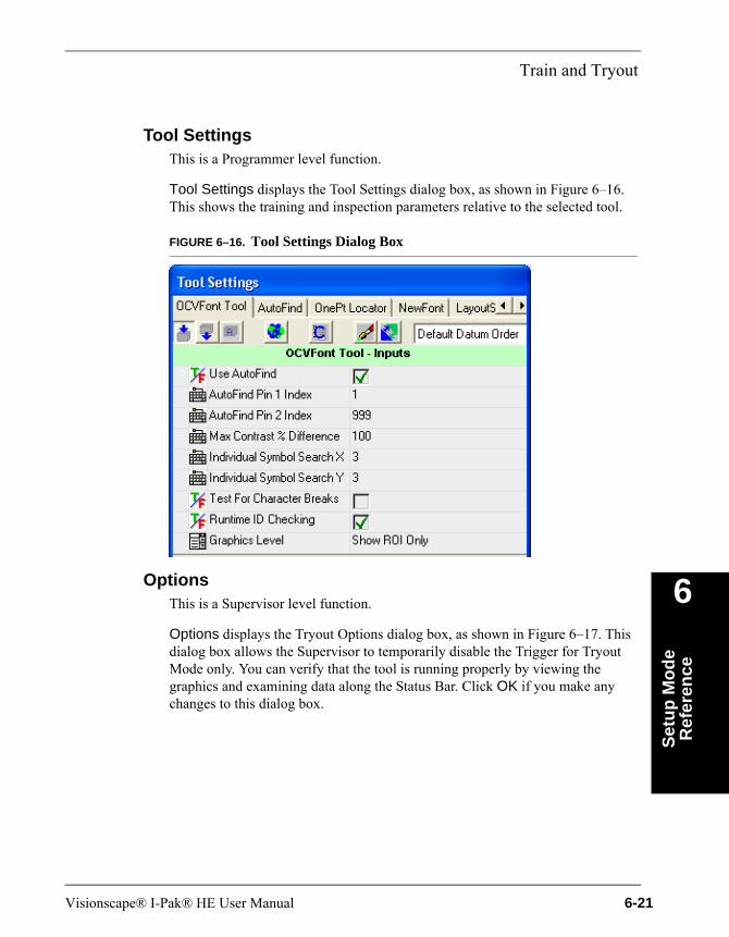
Train and Tryout
Set
up
Mo
de
Ref
eren
ce
6
Tool SettingsThis is a Programmer level function.
Tool Settings displays the Tool Settings dialog box, as shown in Figure 6–16. This shows the training and inspection parameters relative to the selected tool.
FIGURE 6–16. Tool Settings Dialog Box
OptionsThis is a Supervisor level function.
Options displays the Tryout Options dialog box, as shown in Figure 6–17. This dialog box allows the Supervisor to temporarily disable the Trigger for Tryout Mode only. You can verify that the tool is running properly by viewing the graphics and examining data along the Status Bar. Click OK if you make any changes to this dialog box.
Visionscape® I-Pak® HE User Manual 6-21
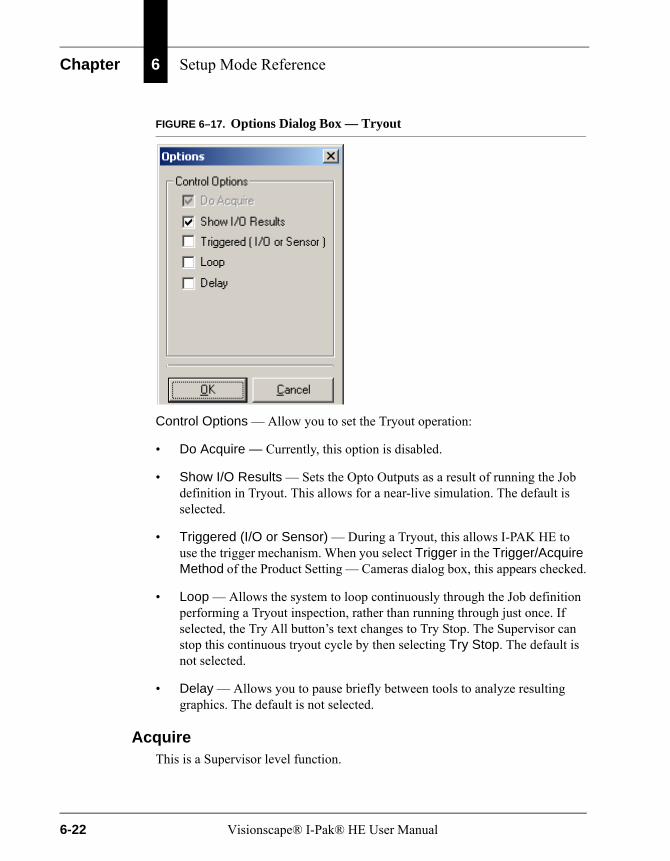
Chapter 6 Setup Mode Reference
FIGURE 6–17. Options Dialog Box — Tryout
Control Options — Allow you to set the Tryout operation:
• Do Acquire — Currently, this option is disabled.
• Show I/O Results — Sets the Opto Outputs as a result of running the Job definition in Tryout. This allows for a near-live simulation. The default is selected.
• Triggered (I/O or Sensor) — During a Tryout, this allows I-PAK HE to use the trigger mechanism. When you select Trigger in the Trigger/Acquire Method of the Product Setting — Cameras dialog box, this appears checked.
• Loop — Allows the system to loop continuously through the Job definition performing a Tryout inspection, rather than running through just once. If selected, the Try All button’s text changes to Try Stop. The Supervisor can stop this continuous tryout cycle by then selecting Try Stop. The default is not selected.
• Delay — Allows you to pause briefly between tools to analyze resulting graphics. The default is not selected.
AcquireThis is a Supervisor level function.
6-22 Visionscape® I-Pak® HE User Manual

Train and Tryout
Set
up
Mo
de
Ref
eren
ce
6
Acquire takes an image using the pre-defined trigger criteria (fire strobe, etc.,) from the Options dialog box. The image is displayed on the display buffer in the lower part of the screen. This is useful when using a strobe, allowing you to view a production image.
The image last Acquired is saved by I-PAK HE. In the Training and Tryout menu, as you go through the Job by clicking Next and Previous, the image displayed is the last runtime image for that Smart Camera. If you are on the Inspection step, it will show you the first snapshot’s image for that inspection.
When you click Acquire or Live, I-PAK HE replaces that stored runtime image with the newly acquired image.
LiveThis is a Supervisor level function.
Live takes a live image from the Smart Camera and displays it on the display buffer in the lower part of the screen. When you click the button once to activate Live Mode, the button appears depressed. The image area is updated dynamically with live video of the image. Click Live again to exit Live Mode, and the button resumes a normal position. Live Mode does not wait for a trigger.
The last image acquired from Live is saved by I-PAK HE. In the Training and Tryout menu, as you go through the Job by clicking Next and Previous, the image displayed is the last runtime image for that Smart Camera. If you are on the Inspection step, it will show you the first snapshot’s image for that inspection.
When you click Acquire or Live, I-PAK HE replaces that stored runtime image with the newly acquired image.
Zoom InZoom In causes the currently displayed image to show more detail.
Zoom OutZoom Out causes the currently displayed image to show less detail.
Try ToolThis is a Supervisor level function.
Try Tool causes the currently selected tool to run. Any tools that the current tool depends on for execution are also run. Runtime debug graphics are displayed over the image. Debug information is displayed in the status bar below the
Visionscape® I-Pak® HE User Manual 6-23
Chapter 6 Setup Mode Reference
image. This selection uses the triggering mechanism you defined in the Tryout options. Be sure to provide a trigger if one is defined in the product.
Try AllThis is a Supervisor level function.
Try All causes all tools in the Job definition to run. Runtime debug graphics are displayed over the image. Debug information is displayed in the Status Bar below the image. Clicking Try All changes the caption to Try Stop. Clicking Try Stop stops the tryout of the program and returns the caption to Try All. This selection uses the triggering mechanism you defined in the Tryout options. Be sure to provide a trigger if one is defined in the product.
Custom SettingsThe OCVFont Tool, OCVRuntimeTool, Trajectory Step and OCRTrainableFont Tool require a Custom Settings dialog box for proper setup and training. In Train and Tryout:
• When the Trajectory Step is selected, the Custom Settings button appears in the toolbar. For more information about using the custom settings for the Trajectory Step, see Chapter 1 of the Visionscape® Tools Reference (on your CD in PDF format).
• When the OCRTrainableFont Tool is selected, the Font Folder button appears in the toolbar. For more information about using the custom settings for the OCRTrainableFont tool, see Chapter 9 of the Visionscape® Tools Reference (on your CD in PDF format).
• When you select either the OCVFont Tool or the OCVRuntimeTool, the Font Editor button appears in the toolbar. For more information about using Font Editor, see “Custom Properties — Create/Modify OCVFonts” on page 5-5.
Exit Training to Main SetupThis is a Supervisor level function.
Exit Training to Main Setup allows the Supervisor to leave Train and Tryout Mode and return to the Setup Mode window. All tools should be trained before clicking Exit Training to Main Setup. The Job definition is saved to the hard drive when Exit Training to Main Setup is selected.
6-24 Visionscape® I-Pak® HE User Manual
Train and Tryout
Set
up
Mo
de
Ref
eren
ce
6
Automatically Setting Tool SettingsThe I-PAK HE interface automatically sets tool settings that are the most useful for users.
• When inserting a Data Matrix Tool, Barcode Tool, Runtime Font Tool or the OCVFont Tool, I-PAK HE automatically selects the .text component of each tool in the Inspection step’s Select Results to Upload field. This data is shown on the Results Display dialog box in the String field, Requested Result and Value fields. Only one .text field can be displayed in the String field.
The .text fields hold either the Font Tool’s current inspected character string, or the Data Matrix or Barcode Tool’s match string.
• When inserting a Data Matrix Tool, its tool graphics are set to show basic graphics.
Special Training of ToolsThe I-PAK HE interface allows for special training of the Barcode Tool, Data Matrix Tool, and OCRTrainableFont Tool when they are used with the Match String Enable checkbox, as shown in Figure 6–16, “Tool Settings Dialog Box,” on page 6-21.
Match StringTypically, these tools perform a read at inspection time, and report these results. Some users want to use a pre-determined code on their product and verify that the string read is what they expect. This concept is known as Match String. With Match String enabled, these tools still perform a read at inspection time and compare it internally against the given Match String to decide if the inspection passed or failed. When the data read is:
• The same as the Match String, this inspection is deemed Pass.
• Not the same as the Match String, this inspection is deemed Fail.
Training Match String Enabled ToolsWhen training a Barcode Tool, a Data Matrix Tool, or an OCRTrainableFont Tool with the Match String enabled, I-PAK HE displays a Match String dialog box, as shown in Figure 6–18. This dialog box is displayed immediately after you select one of these tools either by clicking on the tool or by clicking Next or Previous.
Visionscape® I-Pak® HE User Manual 6-25
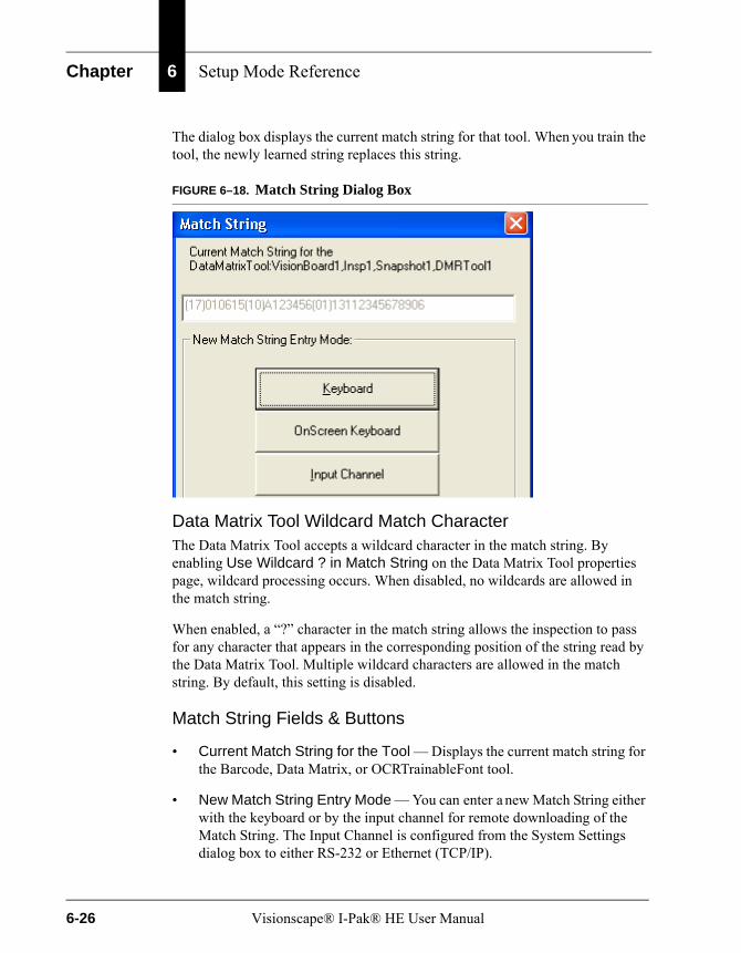
Chapter 6 Setup Mode Reference
The dialog box displays the current match string for that tool. When you train the tool, the newly learned string replaces this string.
FIGURE 6–18. Match String Dialog Box
Data Matrix Tool Wildcard Match CharacterThe Data Matrix Tool accepts a wildcard character in the match string. By enabling Use Wildcard ? in Match String on the Data Matrix Tool properties page, wildcard processing occurs. When disabled, no wildcards are allowed in the match string.
When enabled, a “?” character in the match string allows the inspection to pass for any character that appears in the corresponding position of the string read by the Data Matrix Tool. Multiple wildcard characters are allowed in the match string. By default, this setting is disabled.
Match String Fields & Buttons
• Current Match String for the Tool — Displays the current match string for the Barcode, Data Matrix, or OCRTrainableFont tool.
• New Match String Entry Mode — You can enter a new Match String either with the keyboard or by the input channel for remote downloading of the Match String. The Input Channel is configured from the System Settings dialog box to either RS-232 or Ethernet (TCP/IP).
6-26 Visionscape® I-Pak® HE User Manual
Train and Tryout
Set
up
Mo
de
Ref
eren
ce
6
– Keyboard — To enter the new string with the Keyboard:
• Click Keyboard.
• Type the new string directly into the Match String dialog box.
– To set the tool’s match string to the new match string, click OK.
– To leave the current match string unchanged, click Cancel.
– OnScreen Keyboard — To enter data using the OnScreen Keyboard, click OnScreen Keyboard. For touch screen users, this is useful so that you don’t have to open up and use the I-PAK HE keyboard.
– Input Channel
• RS-232 — To enter the new Match String via RS-232, you need to define the Input Channel on the System Settings menu to be RS-232 and define its RS-232 protocol. For details on how to choose an RS-232 communications port and how to set your I-PAK HE system’s physical communications port, refer to “RS-232” on page 6-64.
• Once the Match String dialog box is displayed, I-PAK HE sends out a message on the RS-232 stating it is ready to receive data. “Waiting for RS-232 Input of Match String for Tool: Device, Inspection Number, Snapshot, Toolname <lf><cr>)” is the message sent out. Then, I-PAK HE begins waiting for the input of the match string.
When I-PAK HE does not receive the match string within the specified timeout period, then this transaction times out. I-PAK HE closes the RS-232 port.
When I-PAK HE does receive the match string, the string is displayed in the Match String dialog box. Click OK to accept this new string or Cancel to revert to the old string.
Note: The RS-232 input of match string must be terminated with either an “Enter” or “Return” character. Once I-PAK HE receives this termination character, it closes the RS-232 port and ignores anything else sent.
Visionscape® I-Pak® HE User Manual 6-27

Chapter 6 Setup Mode Reference
– COM1 Properties — Your RS-232 device settings should be set. This example is from HyperTerminal.
6-28 Visionscape® I-Pak® HE User Manual
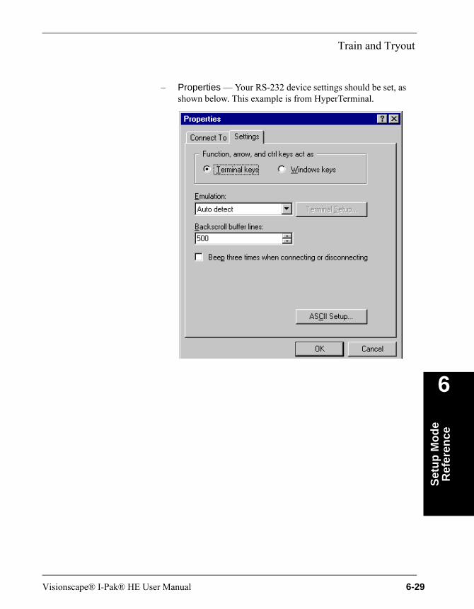
Train and Tryout
Set
up
Mo
de
Ref
eren
ce
6
– Properties — Your RS-232 device settings should be set, as shown below. This example is from HyperTerminal.
Visionscape® I-Pak® HE User Manual 6-29
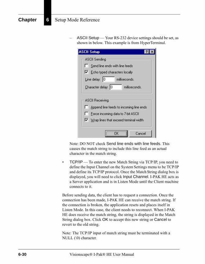
Chapter 6 Setup Mode Reference
– ASCII Setup — Your RS-232 device settings should be set, as shown in below. This example is from HyperTerminal.
Note: DO NOT check Send line ends with line feeds. This causes the match string to include this line feed as an actual character in the match string.
• TCP/IP — To enter the new Match String via TCP/IP, you need to define the Input Channel on the System Settings menu to be TCP/IP and define its TCP/IP protocol. Once the Match String dialog box is displayed, you will need to click Input Channel. I-PAK HE acts as a Server application and is in Listen Mode until the Client machine connects to it.
Before sending data, the client has to request a connection. Once the connection has been made, I-PAK HE can receive the match string. If the connection is broken, the application resets and places itself in Listen Mode. In this case, the client needs to reconnect. When I-PAK HE does receive the match string, the string is displayed in the Match String dialog box. Click OK to accept this new string or Cancel to revert to the old string.
Note: The TCP/IP input of match string must be terminated with a NULL (\0) character.
6-30 Visionscape® I-Pak® HE User Manual

Train and Tryout
Set
up
Mo
de
Ref
eren
ce
6
Note: I-PAK expects the entire match string to be contained within one packet. This means that you cannot type the match string in from a terminal program such as HyperTerminal.
Masking ToolWhen a vision tool that uses an input mask is selected, the Masking Tool menu option becomes available. Clicking on this menu option brings up the ROI Masking Tool dialog box, as shown in Figure 6–19.
FIGURE 6–19. ROI Masking Tool Dialog Box
The dialog box allows a mask to be drawn into the buffer. Then, the associated tool uses this mask at run time. Only tools that have input mask capabilities (in other words, Blob, Flaw, etc.,) can use the ROI Masking Tool.
This dialog box allows you to select a pen style and drawing style for drawing a mask directly into the buffer. You can also use the Fill Style or Eraser Style to fill an enclosed area or erase part of the drawn mask.
• Fill ROI — Fills the entire ROI
• Clear ROI — Clears the entire ROI
When editing the mask is complete, you must close the ROI Masking Tool to continue with Train and Tryout activities.
Visionscape® I-Pak® HE User Manual 6-31
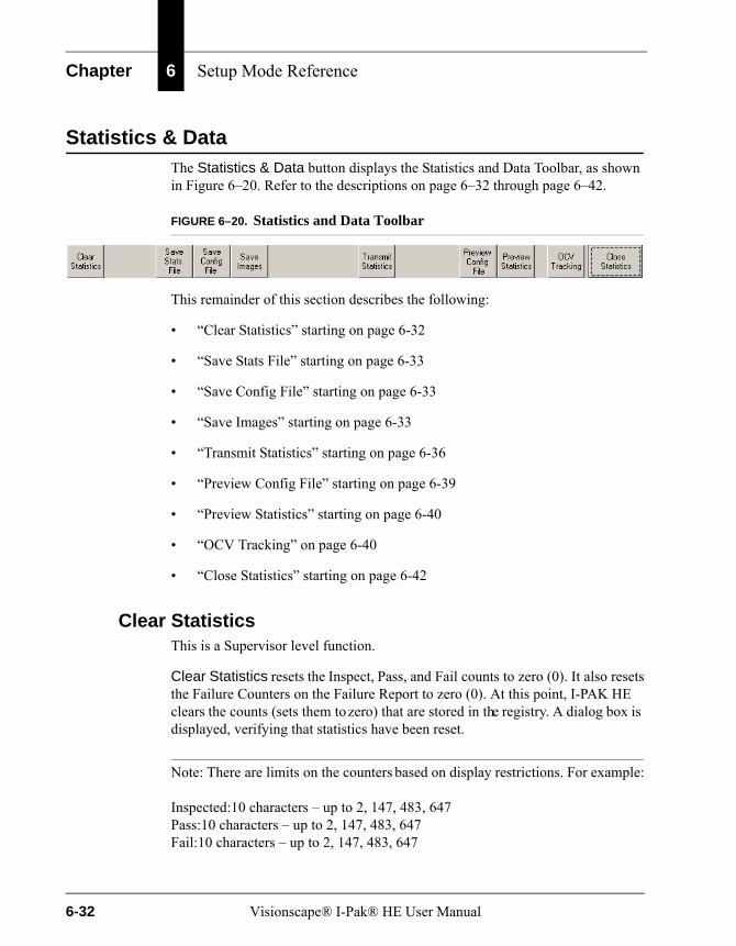
Chapter 6 Setup Mode Reference
Statistics & DataThe Statistics & Data button displays the Statistics and Data Toolbar, as shown in Figure 6–20. Refer to the descriptions on page 6–32 through page 6–42.
FIGURE 6–20. Statistics and Data Toolbar
This remainder of this section describes the following:
• “Clear Statistics” starting on page 6-32
• “Save Stats File” starting on page 6-33
• “Save Config File” starting on page 6-33
• “Save Images” starting on page 6-33
• “Transmit Statistics” starting on page 6-36
• “Preview Config File” starting on page 6-39
• “Preview Statistics” starting on page 6-40
• “OCV Tracking” on page 6-40
• “Close Statistics” starting on page 6-42
Clear StatisticsThis is a Supervisor level function.
Clear Statistics resets the Inspect, Pass, and Fail counts to zero (0). It also resets the Failure Counters on the Failure Report to zero (0). At this point, I-PAK HE clears the counts (sets them to zero) that are stored in the registry. A dialog box is displayed, verifying that statistics have been reset.
Note: There are limits on the counters based on display restrictions. For example:
Inspected:10 characters – up to 2, 147, 483, 647Pass:10 characters – up to 2, 147, 483, 647Fail:10 characters – up to 2, 147, 483, 647
6-32 Visionscape® I-Pak® HE User Manual

Statistics & Data
Set
up
Mo
de
Ref
eren
ce
6
If another inspection occurs after the counters have reached this limit, then the counter is set to “-2,147,483,647” and stops incrementing. This limit, 2,147,483,647, is based on the size of a VB LONG.
Save Stats FileSave Stats File saves the last runtime statistics to a file. The data saved includes: Product, date, time, and counters. When Part 11 is enabled, the statistics file is read-only.
Save Config FileThis is a Supervisor level function.
Save Config File saves a human-readable version of the current Product’s Job definition and its essential data to a file. I-PAK HE prompts for a name. The data saved includes: Product, date/time, counters, Inspected Character String, and Fail Counters. When Part 11 is enabled, the configuration file is read-only.
Note: When there is more than one OCVFont Tool, OCVRuntimeTool, Barcode Tool, or Data Matrix Tool, only the last inspected tool’s string is saved.
Save ImagesSave Images is lossless; it saves every image of the type you specify in Part Image Storage Mode (see page 6–34). After you click Save Images, the Retrieve and Save Image As dialog box is displayed, as shown in Figure 6–21.
Filling in the Retrieve and Save Image As dialog box is a two-step process:
• Before you enter Run Mode, fill in the Part Image Storage information (top half).
• After you exit Run Mode, fill in the Image File Name information (bottom half).
Visionscape® I-Pak® HE User Manual 6-33
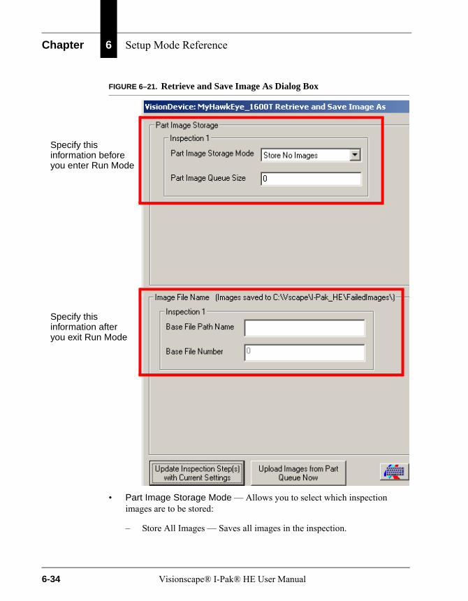
Chapter 6 Setup Mode Reference
FIGURE 6–21. Retrieve and Save Image As Dialog Box
• Part Image Storage Mode — Allows you to select which inspection images are to be stored:
– Store All Images — Saves all images in the inspection.
Specify thisinformation beforeyou enter Run Mode
Specify thisinformation afteryou exit Run Mode
6-34 Visionscape® I-Pak® HE User Manual
Statistics & Data
Set
up
Mo
de
Ref
eren
ce
6
– Store No Images — (Default) Saves no images in the inspection.
– Store Failed Images — Saves all images in the inspection whenever a part fails.
– Store Passed Images — Saves all images in the inspection whenever a part passes.
When an inspection runs and meets the image storage criteria, the Inspection step saves all camera images for that part to memory on the Smart Camera; they can be saved to disk at a later time.
• Part Image Queue Size — Allows you to specify the number of images to be stored.
Note: The total number of images for all inspections cannot exceed 10.
Based on Part Image Storage Mode, images are stored in a first-in, first-out (FIFO) queue. When the number of images stored reaches the size specified by this parameter, the oldest image in the queue is overwritten so that the queue never expands beyond this size. The default value is 0.
Note: After running your inspection, open the Retrieve and Save Image As dialog box to set up Image File Name. Select the path and file names of the currently stored image files on the Smart Camera. This allows the images to be uploaded and saved on the PC.
• Image File Name — When the Inspection step in the current Job has been set up to store images based on the part pass/fail status, you will specify a file destination to which these images should be stored. When the Product is run in a loop, the Inspection step stores images based on its Part Image Storage Mode setting.
– Base File Path Name — Takes a base file name.
– Base File Number — Takes a base file number.
If the Inspection Step was set up to store the last 10 failed images, you could enter c:\fail for the Base File Path Name and 0 for the Base File Number. Then, the 10 failed images would be saved as:
Visionscape® I-Pak® HE User Manual 6-35
Chapter 6 Setup Mode Reference
c:\fail_Snap1_0.tifc:\fail_Snap1_1.tifc:\fail_Snap1_2.tifc:\fail_Snap1_3.tifc:\fail_Snap1_4.tifc:\fail_Snap1_5.tifc:\fail_Snap1_6.tifc:\fail_Snap1_7.tifc:\fail_Snap1_8.tifc:\fail_Snap1_9.tif
When there were two cameras in the inspection, the images would be saved as:
c:\fail_Snap1_0.tif, c:\fail_Snap2_0.tifc:\fail_Snap1_1.tif, c:\fail_Snap2_1.tifc:\fail_Snap1_2.tif, c:\fail_Snap2_2.tifc:\fail_Snap1_3.tif, c:\fail_Snap2_3.tifc:\fail_Snap1_4.tif, c:\fail_Snap2_4.tifc:\fail_Snap1_5.tif, c:\fail_Snap2_5.tifc:\fail_Snap1_6.tif, c:\fail_Snap2_6.tifc:\fail_Snap1_7.tif, c:\fail_Snap2_7.tifc:\fail_Snap1_8.tif, c:\fail_Snap2_8.tifc:\fail_Snap1_9.tif, c:\fail_Snap2_9.tif
In these file names, “Snap1” indicates the first camera, and “Snap2” indicates the second camera. A similar file naming scheme results from an inspection with three or four cameras. The Base File Number can be greater than zero (0), making it easy to identify stored images from different batch runs.
• Update Inspection Step(s) with Current Settings — When you first enable the Part Image Queue on this screen, you should click this button to set your new values into the Job. Then, you can return to Run Mode, and images will be stored in the Part Queue on the Smart Camera.
• Upload Images from Part Queue Now — If you have already enabled the Part Queue on the Smart Camera, and wish to upload the images, click this button, and uploaded images will be saved to file for you.
Transmit StatisticsThis is a Supervisor level function.
6-36 Visionscape® I-Pak® HE User Manual

Statistics & Data
Set
up
Mo
de
Ref
eren
ce
6
Transmit Statistics sends the following statistics to another device through a user-specified RS-232 or Ethernet (TCP/IP) port:
• Product Name.
• Current date and time.
• Inspected string — When the Match String for the Barcode Tool or Data Matrix Tool is used or when the FontTool.text or OCVRunTool.text is uploaded.
• Last Runtime Statistics.
Transmit Statistics sends this data in the following formats:
• RS-232 Protocol & Syntax — The RS-232 protocol and syntax for a transmission of statistics is as follows:
– RS-232 Protocol — The RS-232 default baud rate is 9600, No Parity, 8 data bits and 1 stop bit. Any of these can be changed using the System Setting dialog box — Communications tab.
– RS-232 Syntax for a Single-Camera Job
Product=product_name<lf><cr>Date/Time=mm/dd/yyyy hh:mm:ss <lf><cr>Inspected Characters=inspected_characters <lf><cr>I=# <lf><cr>P=# <lf><cr>R=# <lf><cr><eot><lf><cr>
Note: EOT is the end of text character; (chr(4)) or Ctrl-D in HyperTerminal, LF is the LineFeed character (chr(10), CR is the Carriage Return character (chr(13)).
A dialog box is displayed to the Supervisor, indicating statistics have been sent.
If there are no Inspected Characters in the Job, the third line of data will not be present.
– RS-232 Syntax for a Multi-Camera Job — Each Inspection Step has the following format. Complete data is terminated by the <eot><lf><cr>.
Visionscape® I-Pak® HE User Manual 6-37
Chapter 6 Setup Mode Reference
Product=product_name<lf><cr>Date/Time=mm/dd/yyyy hh:mm:ss <lf><cr>Inspected Characters=inspected_characters1 <lf><cr>I1=# <lf><cr>P1=# <lf><cr>R1=# <lf><cr>Inspected Characters=inspected_characters2 <lf><cr>I2=# <lf><cr>P2=# <lf><cr>R2=# <lf><cr>Inspected Characters=inspected_characters3 <lf><cr>I3=# <lf><cr>P3=# <lf><cr>R3=# <lf><cr>Inspected Characters=inspected_characters4 <lf><cr>I4=# <lf><cr>P4=# <lf><cr>R4=# <lf><cr><eot><lf><cr>
A dialog box is displayed to the Supervisor, indicating statistics have been sent.
When there are no Inspected Characters in that inspection, the Inspected Character line of data will not be present.
• TCP/IP Protocol & Syntax — The TCP/IP protocol and syntax for a transmission of statistics is as follows:
– TCP/IP Protocol — I-PAK HE is the Server. The TCP/IP default Server Port is 7000. You can change any of these using the System Setting dialog box — Communications tab.
– TCP/IP Syntax for Single-Camera Job.
Product=product_name<lf>Date/Time=m/d/yyyy h:mm <lf>Inspected Characters=inspected_characters <lf>I=# <lf>P=# <lf>R=# <lf><cr>
6-38 Visionscape® I-Pak® HE User Manual

Statistics & Data
Set
up
Mo
de
Ref
eren
ce
6
If there are no Inspected Characters in the Job, the third line of data will not be present.
– TCP/IP Syntax for a Multi-Camera Job.
Product=product_name<lf>Date/Time=m/d/yyyy h:mm <lf>Inspected Characters=inspected_characters1 <lf>I1=# <lf>P1=# <lf>R1=# <lf>Inspected Characters=inspected_characters2 <lf>I2=# <lf>P2=# <lf>R2=# <lf>Inspected Characters=inspected_characters3 <lf>I3=# <lf>P3=# <lf>R3=# <lf>Inspected Characters=inspected_characters4 <lf>I4=# <lf>P4=# <lf>R4=# <lf><cr>
If there are no Inspected Characters in that inspection, the Inspected Character line of data will not be present.
Preview Config FileThis is a Supervisor level function.
Preview Config File displays the contents of the current Product’s Data File Statistics, as shown in Figure 6–22.
Visionscape® I-Pak® HE User Manual 6-39

Chapter 6 Setup Mode Reference
FIGURE 6–22. Preview Config File
Preview StatisticsThis is a Supervisor level function.
Preview Statistics displays the dialog box shown in Figure 6–23, which displays the current runtime statistics.
FIGURE 6–23. I-PAK HE Dialog Box — Preview Statistics
OCV TrackingYou must enable System Settings > Training and Results > Enable OCV Failure Tracking for the OCV Tracking button to be visible.
When you click OCV Tracking, the OCV Failure Tracking dialog box is displayed, as shown in Figure 6–24. It lists all of the OCV tools that are in the current product definition.
6-40 Visionscape® I-Pak® HE User Manual
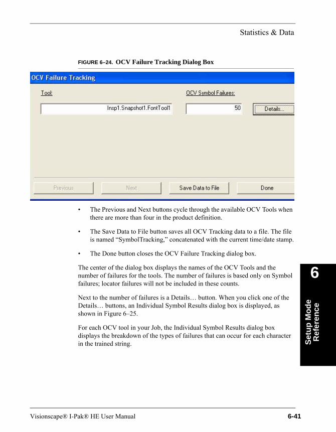
Statistics & Data
Set
up
Mo
de
Ref
eren
ce
6
FIGURE 6–24. OCV Failure Tracking Dialog Box
• The Previous and Next buttons cycle through the available OCV Tools when there are more than four in the product definition.
• The Save Data to File button saves all OCV Tracking data to a file. The file is named “SymbolTracking,” concatenated with the current time/date stamp.
• The Done button closes the OCV Failure Tracking dialog box.
The center of the dialog box displays the names of the OCV Tools and the number of failures for the tools. The number of failures is based only on Symbol failures; locator failures will not be included in these counts.
Next to the number of failures is a Details… button. When you click one of the Details… buttons, an Individual Symbol Results dialog box is displayed, as shown in Figure 6–25.
For each OCV tool in your Job, the Individual Symbol Results dialog box displays the breakdown of the types of failures that can occur for each character in the trained string.
Visionscape® I-Pak® HE User Manual 6-41

Chapter 6 Setup Mode Reference
FIGURE 6–25. Individual Symbol Results Dialog Box
Close StatisticsThis is a Supervisor level function.
Close Statistics quits this Statistics and Data Toolbar and returns you to the I-PAK HE Setup Mode window.
Advanced SettingsAdvanced Settings displays the Advanced Settings Toolbar, as shown in Figure 6–26. The Advanced Settings Toolbar is accessed only via Programmer Mode.
FIGURE 6–26. Advanced Settings Toolbar
This remainder of this section describes the following:
6-42 Visionscape® I-Pak® HE User Manual

Advanced Settings
Set
up
Mo
de
Ref
eren
ce
6
• “Create A Product” starting on page 6-43
• “Save Product” starting on page 6-54
• “Product Settings” starting on page 6-56
• “System Settings” starting on page 6-62
• “Edit Tool Set” starting on page 6-95
• “Tool Settings” starting on page 6-96
• “Windows Explorer” starting on page 6-97
• “Close Advanced” starting on page 6-98
Create A ProductThis is a Programmer level function.
The Create A Product button allows the Programmer to define a new product. The Create A Product wizard is a series of interconnected dialog boxes that navigate the Programmer from the Product Settings to the System Settings to a flowchart-like interface for Step Program creation. After defining all the tools, the Programmer is taken into Wizard Training mode in order to train the tools. After you successfully train all the tools, you can perform a tryout in Tryout Mode.
For consistency of menu flow description, all steps and sequences are shown and all general details listed.
Program Settings Dialog BoxesIn these dialog boxes (Figure 6–27, Figure 6–28, Figure 6–29), the Programmer defines the camera settings and I/O configuration.
Click Next to move ahead to the next menu in the Create A Product wizard series.
Visionscape® I-Pak® HE User Manual 6-43
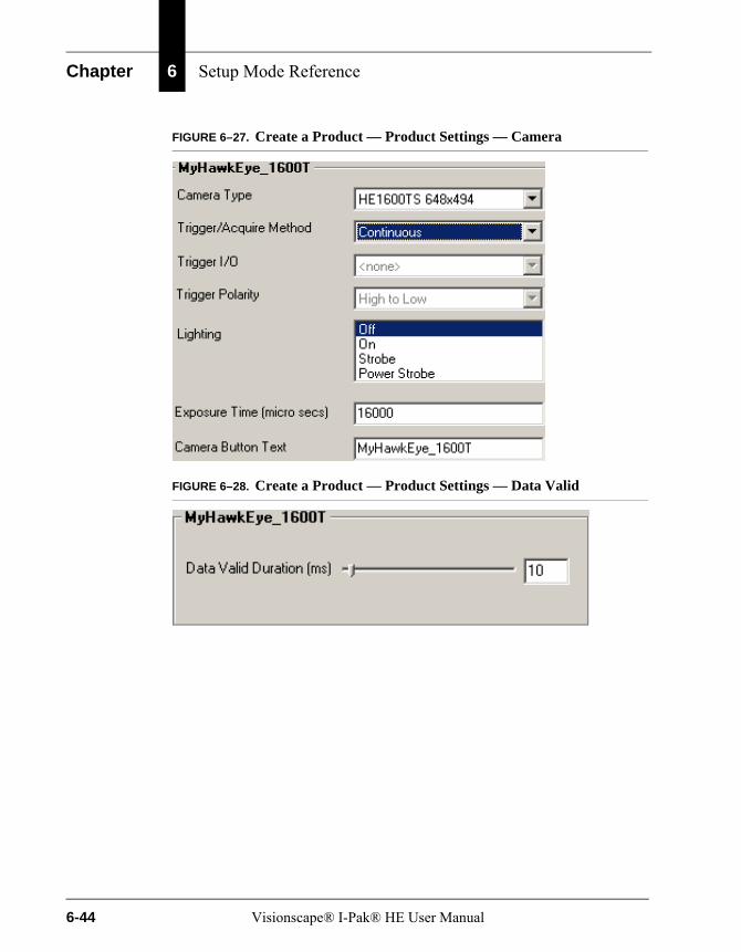
Chapter 6 Setup Mode Reference
FIGURE 6–27. Create a Product — Product Settings — Camera
FIGURE 6–28. Create a Product — Product Settings — Data Valid
6-44 Visionscape® I-Pak® HE User Manual
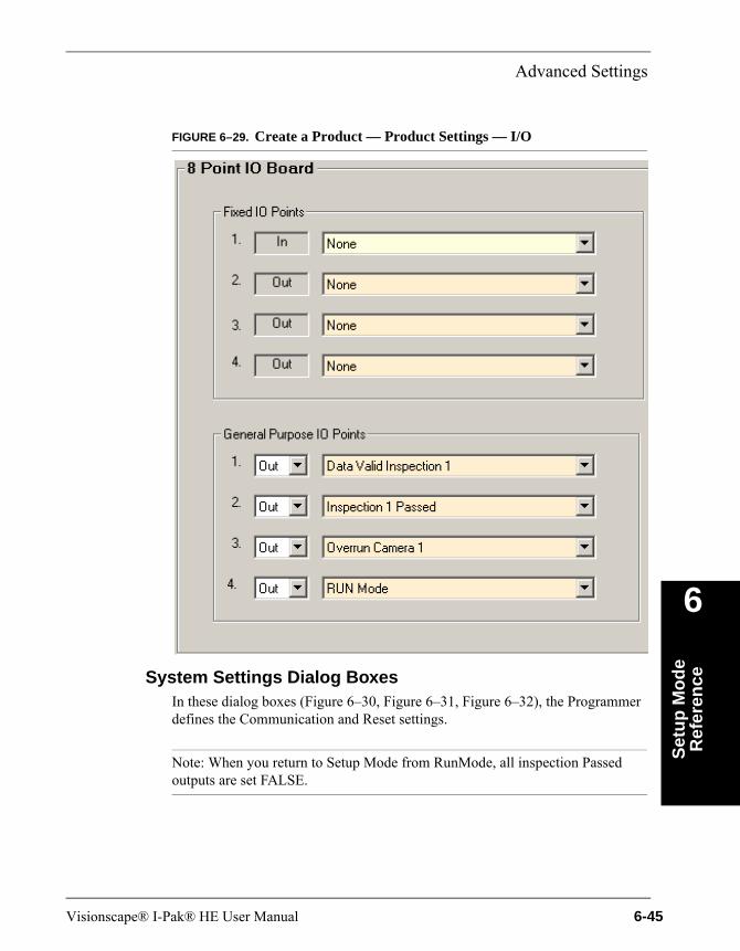
Advanced Settings
Set
up
Mo
de
Ref
eren
ce
6
FIGURE 6–29. Create a Product — Product Settings — I/O
System Settings Dialog BoxesIn these dialog boxes (Figure 6–30, Figure 6–31, Figure 6–32), the Programmer defines the Communication and Reset settings.
Note: When you return to Setup Mode from RunMode, all inspection Passed outputs are set FALSE.
Visionscape® I-Pak® HE User Manual 6-45
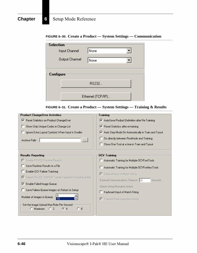
Chapter 6 Setup Mode Reference
FIGURE 6–30. Create a Product — System Settings — Communication
FIGURE 6–31. Create a Product — System Settings — Training & Results
6-46 Visionscape® I-Pak® HE User Manual

Advanced Settings
Set
up
Mo
de
Ref
eren
ce
6
FIGURE 6–32. Create a Product — System Settings — General
At this point:
• Clicking Quit Product Creation aborts the product creation during Product Settings and System Settings.
• Clicking OK takes you to the Step Program Creation dialog boxes (Figure 6–33 through Figure 6–36).
Step Program Dialog BoxesThese dialog boxes are a visual representation of the tools to be programmed and used in the product definition. A new product definition displays Camera, Inspection, and Acquire. For this window, the glidepoint input device is needed with the touchscreen to support 2-button mouse controls.
Visionscape® I-Pak® HE User Manual 6-47

Chapter 6 Setup Mode Reference
FIGURE 6–33. Create a Product — Acquire
Right click on Acquire 1. A screen similar to the one in Figure 6–34 is displayed.
FIGURE 6–34. Create a Product — Step Program — Insert A Step
Highlight a step in the Insert A Step dialog box and click OK. A screen similar to the one in Figure 6–35 is displayed.
6-48 Visionscape® I-Pak® HE User Manual
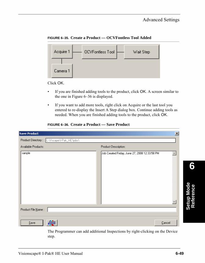
Advanced Settings
Set
up
Mo
de
Ref
eren
ce
6
FIGURE 6–35. Create a Product — OCVFontless Tool Added
Click OK.
• If you are finished adding tools to the product, click OK. A screen similar to the one in Figure 6–36 is displayed.
• If you want to add more tools, right click on Acquire or the last tool you entered to re-display the Insert A Step dialog box. Continue adding tools as needed. When you are finished adding tools to the product, click OK.
FIGURE 6–36. Create a Product — Save Product
The Programmer can add additional Inspections by right-clicking on the Device step.
Visionscape® I-Pak® HE User Manual 6-49

Chapter 6 Setup Mode Reference
Right-clicking on the Acquire step results in the Insert A Step dialog box being displayed. This dialog box displays the names of steps that can be inserted into an Acquire step. Once a Device, Inspection, or Snapshot block has been inserted, it can be changed by right-clicking on it. Left-clicking on a primary tool deletes all secondary tools.
Right-clicking on a tool button, such as the Barcode Tool shown in Figure 6–34, displays the Insert A Step dialog box with all possible vision tools. The Programmer selects a tool and clicks on Insert Before, Insert After, or Insert Into. Clicking OK causes an Insert Into action.
Right-clicking on a secondary tool button displays the Insert A Step dialog box with all possible vision tools. The Programmer selects a tool and clicks Insert Before or Insert After. Click OK to cause an Insert After action.
The Programmer can delete any primary or secondary tool at any location by left-clicking on the tool. The Delete Tool/SubTool dialog box is displayed. This will prompt the Programmer to confirm the action. Click OK to delete. Click Cancel to abort this action.
This process continues until the Programmer has completed the selection of tools in this Product build. Click OK. The Programmer is prompted to name the Product. Click OK to save the Product and the Product name associated with this Product.
During Product creation, in the System Settings > General dialog box, if Reset Statistics on Product ChangeOver is checked, the appropriate dialog box is displayed.
Special Features of Tools & Steps in Job CreationI-PAK HE uses the Visionscape® Toolset as the basis for the I-PAK HE Toolset. However, I-PAK HE has its own rules, which differ from Visionscape®, and Job creation and implementation, which also differ from FrontRunner™. Below are some of these I-PAK HE unique features and implementation details.
Note: Because of these differences, the Programmer should NEVER create a Job using FrontRunner™ and then try to make I-PAK HE use it.
• FrontRunner™ uses a Job file that consists of only an .avp file. I-PAK HE uses an .avp file and an .avpsys file, as well, to store many other details about its Job. If the Programmer tries to use a FrontRunner™ Job in I-PAK
6-50 Visionscape® I-Pak® HE User Manual
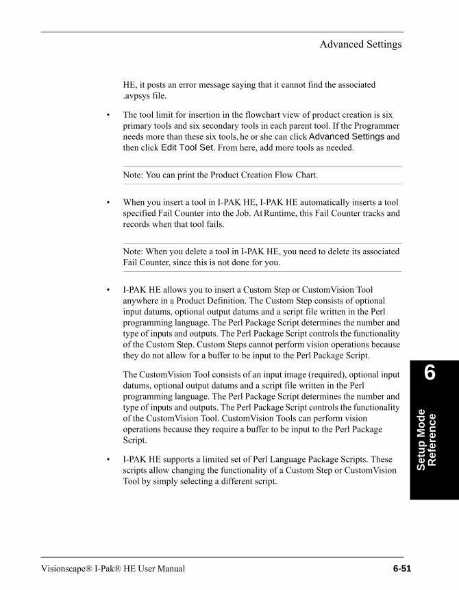
Advanced Settings
Set
up
Mo
de
Ref
eren
ce
6
HE, it posts an error message saying that it cannot find the associated .avpsys file.
• The tool limit for insertion in the flowchart view of product creation is six primary tools and six secondary tools in each parent tool. If the Programmer needs more than these six tools, he or she can click Advanced Settings and then click Edit Tool Set. From here, add more tools as needed.
Note: You can print the Product Creation Flow Chart.
• When you insert a tool in I-PAK HE, I-PAK HE automatically inserts a tool specified Fail Counter into the Job. At Runtime, this Fail Counter tracks and records when that tool fails.
Note: When you delete a tool in I-PAK HE, you need to delete its associated Fail Counter, since this is not done for you.
• I-PAK HE allows you to insert a Custom Step or CustomVision Tool anywhere in a Product Definition. The Custom Step consists of optional input datums, optional output datums and a script file written in the Perl programming language. The Perl Package Script determines the number and type of inputs and outputs. The Perl Package Script controls the functionality of the Custom Step. Custom Steps cannot perform vision operations because they do not allow for a buffer to be input to the Perl Package Script.
The CustomVision Tool consists of an input image (required), optional input datums, optional output datums and a script file written in the Perl programming language. The Perl Package Script determines the number and type of inputs and outputs. The Perl Package Script controls the functionality of the CustomVision Tool. CustomVision Tools can perform vision operations because they require a buffer to be input to the Perl Package Script.
• I-PAK HE supports a limited set of Perl Language Package Scripts. These scripts allow changing the functionality of a Custom Step or CustomVision Tool by simply selecting a different script.
Visionscape® I-Pak® HE User Manual 6-51
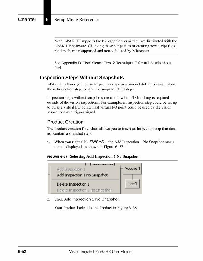
Chapter 6 Setup Mode Reference
Note: I-PAK HE supports the Package Scripts as they are distributed with the I-PAK HE software. Changing these script files or creating new script files renders them unsupported and non-validated by Microscan.
See Appendix D, “Perl Gems: Tips & Techniques,” for full details about Perl.
Inspection Steps Without SnapshotsI-PAK HE allows you to use Inspection steps in a product definition even when those Inspection steps contain no snapshot child steps.
Inspection steps without snapshots are useful when I/O handling is required outside of the vision inspections. For example, an Inspection step could be set up to pulse a virtual I/O point. That virtual I/O point could be used by the vision inspections as a trigger signal.
Product CreationThe Product creation flow chart allows you to insert an Inspection step that does not contain a snapshot step.
1. When you right click SWSYS1, the Add Inspection 1 No Snapshot menu item is displayed, as shown in Figure 6–37.
FIGURE 6–37. Selecting Add Inspection 1 No Snapshot
2. Click Add Inspection 1 No Snapshot.
Your Product looks like the Product in Figure 6–38.
6-52 Visionscape® I-Pak® HE User Manual
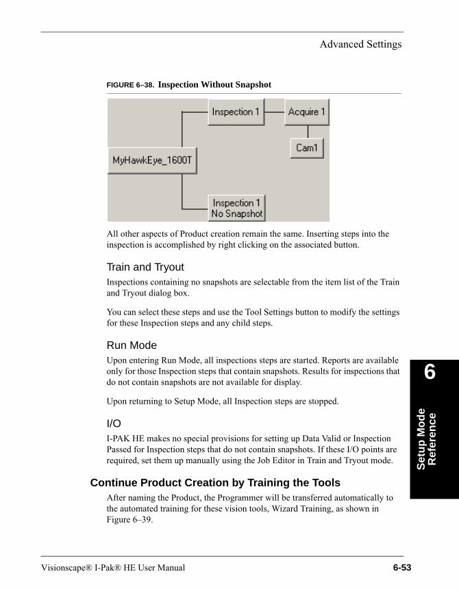
Advanced Settings
Set
up
Mo
de
Ref
eren
ce
6
FIGURE 6–38. Inspection Without Snapshot
All other aspects of Product creation remain the same. Inserting steps into the inspection is accomplished by right clicking on the associated button.
Train and TryoutInspections containing no snapshots are selectable from the item list of the Train and Tryout dialog box.
You can select these steps and use the Tool Settings button to modify the settings for these Inspection steps and any child steps.
Run ModeUpon entering Run Mode, all inspections steps are started. Reports are available only for those Inspection steps that contain snapshots. Results for inspections that do not contain snapshots are not available for display.
Upon returning to Setup Mode, all Inspection steps are stopped.
I/OI-PAK HE makes no special provisions for setting up Data Valid or Inspection Passed for Inspection steps that do not contain snapshots. If these I/O points are required, set them up manually using the Job Editor in Train and Tryout mode.
Continue Product Creation by Training the ToolsAfter naming the Product, the Programmer will be transferred automatically to the automated training for these vision tools, Wizard Training, as shown in Figure 6–39.
Visionscape® I-Pak® HE User Manual 6-53
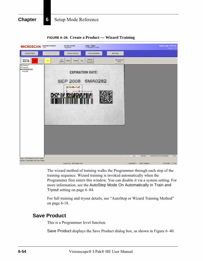
Chapter 6 Setup Mode Reference
FIGURE 6–39. Create a Product — Wizard Training
The wizard method of training walks the Programmer through each step of the training sequence. Wizard training is invoked automatically when the Programmer first enters this window. You can disable it via a system setting. For more information, see the AutoStep Mode On Automatically in Train and Tryout setting on page 6–84.
For full training and tryout details, see “AutoStep or Wizard Training Method” on page 6-18.
Save ProductThis is a Programmer level function.
Save Product displays the Save Product dialog box, as shown in Figure 6–40.
6-54 Visionscape® I-Pak® HE User Manual

Advanced Settings
Set
up
Mo
de
Ref
eren
ce
6
FIGURE 6–40. Save Product Dialog Box
Type the Product File Name and click Save. I-PAK HE saves the current product name and Job to disk. By default, this button is not selected until you click on it.
The product description text can be up to 1000 characters. This allows each product definition to have a unique description.
Note: If you want to add a new line in the product description field, you must press Ctrl-Enter to have the new line appear (if you press Enter by itself, you will immediately save the product).
Note: There is a special I-PAK HE feature, available for our advanced Programmers, when using the Product Name “ByPass”. When doing a Product ChangeOver, the product named “bypass.avp” only appears in the list if the current access level is Programmer. This allows for customer-specific Jobs to be run by Programmers. For example, the “ByPass” product could be set up to bypass the I-PAK HE vision processing and allow a line to clear old product before beginning the inspection of new product.
Visionscape® I-Pak® HE User Manual 6-55
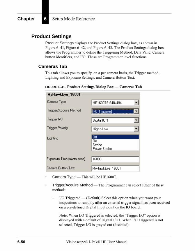
Chapter 6 Setup Mode Reference
Product SettingsProduct Settings displays the Product Settings dialog box, as shown in Figure 6–41, Figure 6–42, and Figure 6–43. The Product Settings dialog box allows the Programmer to define the Triggering Method, Data Valid, Camera button identifiers, and I/O. These are Programmer level functions.
Cameras TabThis tab allows you to specify, on a per camera basis, the Trigger method, Lighting and Exposure Settings, and Camera Button Text.
FIGURE 6–41. Product Settings Dialog Box — Cameras Tab
• Camera Type — This will be HE1600T.
• Trigger/Acquire Method — The Programmer can select either of these methods:
– I/O Triggered — (Default) Select this option when you want your inspections to run only after an external trigger signal has been received on a pre-defined Digital Input point on the IO board.
Note: When I/O Triggered is selected, the “Trigger I/O” option is displayed with a default of Digital I/O1. When I/O Triggered is not selected, Trigger I/O is grayed out (disabled).
6-56 Visionscape® I-Pak® HE User Manual

Advanced Settings
Set
up
Mo
de
Ref
eren
ce
6
– Continuous — When you select this option, your inspections will run in a continuous loop, and will not wait for a trigger signal. For debug purposes only, and never a Production mode setting. The default is not selected.
• Trigger I/O — When the Programmer selects a Trigger/Acquire Method of I/O Triggered, this list will contain all Digital IO points configured currently as inputs, as well as virtual IO points.
Default: Digital I/O 1Range: Any valid physical input point or virtual I/O point
• Trigger Polarity — When the Programmer selects a Trigger/Acquire Method of I/O Triggered, Trigger Polarity is designated.
Default: High to Low
• Lighting— Controls how the Light Port Connector on the HawkEye 1600T is used.:
– Off — No power is supplied to the Light Port Connector
– On — Continuous power is supplied, meaning a connected light head would be on all the time
– Strobe — Pulse equal to exposure duration
– Power Strobe — Short 24V pulse
• Exposure Time (micro secs) — Use this value to set the amount of time, in micro seconds, that the Smart Camera’s CCD will integrate light. Exposure Time can freeze motion when you are not using a strobe; if you are using a strobe, it can prevent ambient light from affecting your image.
Note: If Lighting is set to Power Strobe:
Maximum Exposure Time = 1000 micro secondsMinimum Exposure Time = Depends on the camera definition file
• Camera Button Text — The Programmer can modify the contents of the Camera Button text to better reflect the inspection being done by that Smart Camera. The default text is the name of your Smart Camera. The maximum length for the camera button text is 30 characters.
Visionscape® I-Pak® HE User Manual 6-57
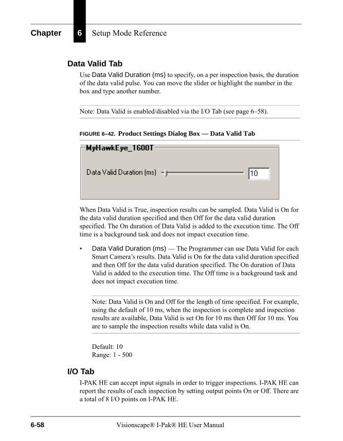
Chapter 6 Setup Mode Reference
Data Valid TabUse Data Valid Duration (ms) to specify, on a per inspection basis, the duration of the data valid pulse. You can move the slider or highlight the number in the box and type another number.
Note: Data Valid is enabled/disabled via the I/O Tab (see page 6–58).
FIGURE 6–42. Product Settings Dialog Box — Data Valid Tab
When Data Valid is True, inspection results can be sampled. Data Valid is On for the data valid duration specified and then Off for the data valid duration specified. The On duration of Data Valid is added to the execution time. The Off time is a background task and does not impact execution time.
• Data Valid Duration (ms) — The Programmer can use Data Valid for each Smart Camera’s results. Data Valid is On for the data valid duration specified and then Off for the data valid duration specified. The On duration of Data Valid is added to the execution time. The Off time is a background task and does not impact execution time.
Note: Data Valid is On and Off for the length of time specified. For example, using the default of 10 ms, when the inspection is complete and inspection results are available, Data Valid is set On for 10 ms then Off for 10 ms. You are to sample the inspection results while data valid is On.
Default: 10Range: 1 - 500
I/O TabI-PAK HE can accept input signals in order to trigger inspections. I-PAK HE can report the results of each inspection by setting output points On or Off. There are a total of 8 I/O points on I-PAK HE.
6-58 Visionscape® I-Pak® HE User Manual
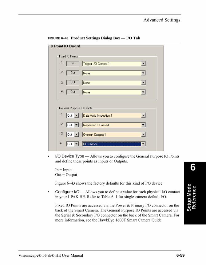
Advanced Settings
Set
up
Mo
de
Ref
eren
ce
6
FIGURE 6–43. Product Settings Dialog Box — I/O Tab
• I/O Device Type — Allows you to configure the General Purpose IO Points and define these points as Inputs or Outputs.
In = InputOut = Output
Figure 6–43 shows the factory defaults for this kind of I/O device.
• Configure I/O — Allows you to define a value for each physical I/O contact in your I-PAK HE. Refer to Table 6–1 for single-camera default I/O.
Fixed IO Points are accessed via the Power & Primary I/O connector on the back of the Smart Camera. The General Purpose IO Points are accessed via the Serial & Secondary I/O connector on the back of the Smart Camera. For more information, see the HawkEye 1600T Smart Camera Guide.
Visionscape® I-Pak® HE User Manual 6-59
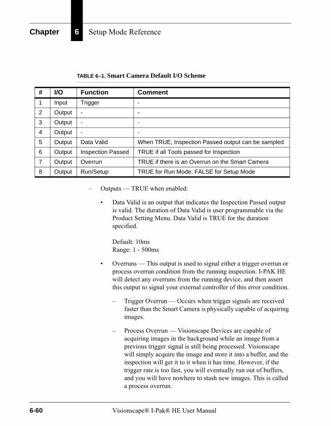
Chapter 6 Setup Mode Reference
– Outputs — TRUE when enabled:
• Data Valid is an output that indicates the Inspection Passed output is valid. The duration of Data Valid is user programmable via the Product Setting Menu. Data Valid is TRUE for the duration specified.
Default: 10msRange: 1 - 500ms
• Overruns — This output is used to signal either a trigger overrun or process overrun condition from the running inspection. I-PAK HE will detect any overruns from the running device, and then assert this output to signal your external controller of this error condition.
– Trigger Overrun — Occurs when trigger signals are received faster than the Smart Camera is physically capable of acquiring images.
– Process Overrun — Visionscape Devices are capable of acquiring images in the background while an image from a previous trigger signal is still being processed. Visionscape will simply acquire the image and store it into a buffer, and the inspection will get it to it when it has time. However, if the trigger rate is too fast, you will eventually run out of buffers, and you will have nowhere to stash new images. This is called a process overrun.
TABLE 6–1. Smart Camera Default I/O Scheme
# I/O Function Comment
1 Input Trigger -
2 Output - -
3 Output - -
4 Output - -
5 Output Data Valid When TRUE, Inspection Passed output can be sampled
6 Output Inspection Passed TRUE if all Tools passed for Inspection
7 Output Overrun TRUE if there is an Overrun on the Smart Camera
8 Output Run/Setup TRUE for Run Mode; FALSE for Setup Mode
6-60 Visionscape® I-Pak® HE User Manual

Advanced Settings
Set
up
Mo
de
Ref
eren
ce
6
• Inspection Passed is an output to indicate a good part. This Output will be turned ON if the inspection passed all of the criteria set by you, it will be turned OFF if your inspection failed.
Note: When you return to Setup Mode from Run Mode, all Inspection Passed outputs are set FALSE.
• Run Mode — This output will turn ON when you switch I-PAK HE to Run Mode, and it will turn OFF when you return to Setup Mode. This can be checked by an external controller to verify that I-PAK HE is ready to run.
• HeartBeat — By default, this output is disabled. When enabled, at system start-up time, the HeartBeat output begins its operation by being set TRUE for 1 second and then FALSE for 1 second, alternatively, to indicate that I-PAK HE is functional. At this one second interval, the I-PAK HE software is verifying the operational mode of the Smart Camera. If the Smart Camera is not operational, the HeartBeat output is set to FALSE and remains FALSE until the Smart Camera is again operational. When in Setup Mode and training OCVFont Tools, the timing of HeartBeat may deviate from 1 second True, 1 second False.
The HeartBeat output is generated by I-PAK HE. During periods of heavy PC loading, the HeartBeat Output frequency can change. For example, during a download, the HeartBeat will not pulse, because all resources are downloading the Job to the Smart Camera(s). PLC monitoring must be written with these scenarios in mind. For example, monitor the HeartBeat every 1 second when the Run Mode output is also asserted.
While in Setup Mode, the Run Mode/Setup Mode Output is set to FALSE. During Run Mode, the Run Mode/Setup Mode Output is set to TRUE. External monitoring of the I/O point indicates when I-PAK HE is ready to run.
– Inputs — Must be set to “In” to Enable:
• Inspection Trigger is an input that instructs I-PAK HE to conduct one inspection cycle for each inspection trigger I-PAK HE receives from an external source. The default for this is I/O 1 of the Fixed IO Points.
Visionscape® I-Pak® HE User Manual 6-61
Chapter 6 Setup Mode Reference
• You may use an input as a handshake to clear a pass output.
System SettingsThe System Settings dialog box allows the Programmer to:
• Define and configure the Input and Output Channels
• Define automatic Product ChangeOver activities:
– Resetting statistics
– Resetting failures
– Setting the archive path
– Showing only unique codes in change lot
– Ignoring extra layout symbols
• Define training Session activities:
– Autosave
– Resetting statistics
– Resetting failures
– AutoStep Mode default on/off in Training
– Go directly into Training when you exit Run Mode
– Train Multiple OCV Tools
• Define an End Batch option
• Enable the 21 CFR Part 11 Compliance options:
– Login capability
– Configuration Audit trail
– Login Passwords Expirations
– Login Prompt on Training Feature
These are Programmer level functions.
6-62 Visionscape® I-Pak® HE User Manual

Advanced Settings
Set
up
Mo
de
Ref
eren
ce
6
For the System Settings dialog box with General tab selected, see “System Settings — General Tab” on page 6-90.
The remainder of this section describes:
• “System Settings — Communication Tab” starting on page 6-63
• “System Settings — Training and Results Tab” starting on page 6-71
• “System Settings — General Tab” starting on page 6-90
System Settings — Communication Tab
FIGURE 6–44. System Settings Dialog Box — Communication Tab
SelectionThis section allows you to define the Input and Output Channel to communicate to a host for download of match string and OCVFont Tool string:
• Input Channel — Choose from None (default), RS-232, or Ethernet.
• Output Channel — Choose from None (default), RS-232, or Ethernet.
ConfigureThis section allows you to configure the Input and Output Channel, and contains the following buttons:
• “RS-232” on page 6-64
• “Ethernet (TCP/IP)” on page 6-66
Visionscape® I-Pak® HE User Manual 6-63

Chapter 6 Setup Mode Reference
RS-232
After you click on this button, the Configure Communication dialog box is displayed, as shown in Figure 6–45. You can use the defaults or customize your Communications ports.
FIGURE 6–45. Configure Communication Dialog Box — RS-232 Settings
I-PAK HE supports two RS-232 ports. They must be configured as COM1 and COM2.
If a COM Port is already used by another program, it is displayed inside the frame of the port (“COM Port x used by another program or not available”) and the Input fields are hidden (see Figure 6–46 on page 6-66). If a COM Port is not available (Hardware), it is displayed inside the frame of the port (“COM Port x used by another program or not available”) and the Input fields are hidden (see Figure 6–46 on page 6-66).
This dialog box is driven by the type of Protocol being used.
6-64 Visionscape® I-Pak® HE User Manual

Advanced Settings
Set
up
Mo
de
Ref
eren
ce
6
• Protocol — Defines which RS-232 protocol scheme is used.
– I-PAK HE Enclosure Standard — This is the default; it means that RS-232 COM Port 1 is used for all RS-232 Communications. When this protocol is used, you cannot use the other ports or change their settings.
– I-PAK HE Selectable Main Port — I-PAK HE expects the RS-232 communications to be made through the COM Port indicated by the Main COM Port item on the RS-232 Configuration screen.
• RS-232 Settings — You can define the RS-232 Settings as follows:
– Baud Rate — Default of 9600. Range is 110 to 115200.
– Parity — Default of None. Range includes None, Even, Odd.
– Data Bits — Default of 8. Range includes 4, 5, 6, 7, 8.
– Stop Bits — Default of 1. Range includes 1, 1.5, 2.
– Timeout (Seconds) — Default of 15 seconds. Range is 1 to 99.
– Field Delimiter Char — Default of “,”. Range of “,”, “*” and “#”.
– Main Comm Port — This setting selects between the two available COM Ports in I-PAK HE. This setting can only be selected when the Protocol is set to “I-PAK HE Selectable Main Port”.
Default: Comm Port 1Range: 1 to 2
Visionscape® I-Pak® HE User Manual 6-65
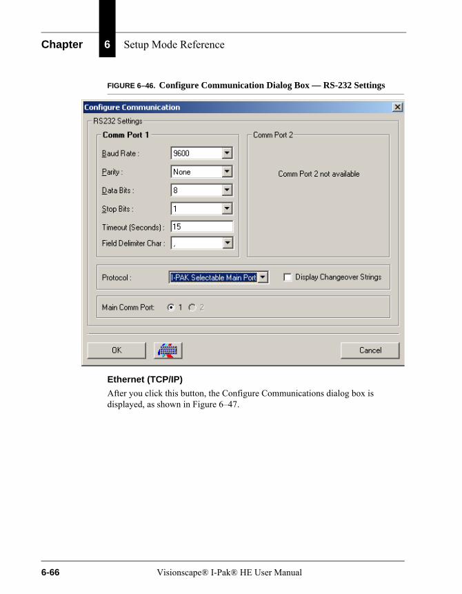
Chapter 6 Setup Mode Reference
FIGURE 6–46. Configure Communication Dialog Box — RS-232 Settings
Ethernet (TCP/IP)
After you click this button, the Configure Communications dialog box is displayed, as shown in Figure 6–47.
6-66 Visionscape® I-Pak® HE User Manual
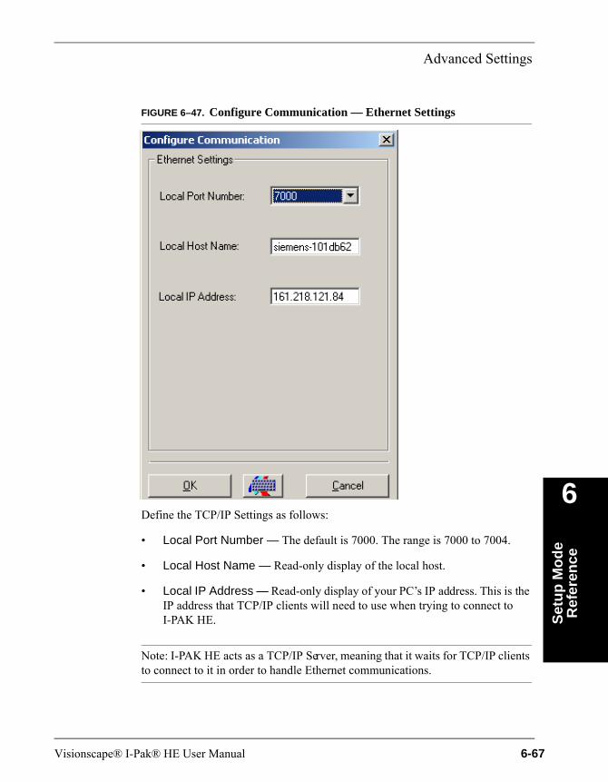
Advanced Settings
Set
up
Mo
de
Ref
eren
ce
6
FIGURE 6–47. Configure Communication — Ethernet Settings
Define the TCP/IP Settings as follows:
• Local Port Number — The default is 7000. The range is 7000 to 7004.
• Local Host Name — Read-only display of the local host.
• Local IP Address — Read-only display of your PC’s IP address. This is the IP address that TCP/IP clients will need to use when trying to connect to I-PAK HE.
Note: I-PAK HE acts as a TCP/IP Server, meaning that it waits for TCP/IP clients to connect to it in order to handle Ethernet communications.
Visionscape® I-Pak® HE User Manual 6-67
Chapter 6 Setup Mode Reference
Remote Commands Supported by RS-232 and Ethernet
Remote commands allow an external device or computer to perform a limited set of functions on I-PAK HE. These functions can be accomplished through either RS-232 or Ethernet, depending on the selected Input Channel. The commands are accepted by I-PAK HE in either Run Mode or Setup Mode. Using remote commands, you can clear statistics, retrieve statistics, enter Setup Mode, enter Run Mode, and change product. The syntax of these commands is:
• Retrieve Statistics: RETRIEVESTATS <EOT>
• Clear Statistics: CLEARSTATISTICS <EOT>
• Go To Setup Mode: ENTERSETUPMODE<EOT>
• Go To Run Mode: ENTERRUNMODE<EOT>
• Change Product: CHANGEPRODUCT<sp>newproductname<EOT>
• Lot Change: CHANGELAYOUT:path:newstring<EOT>
Where:
• The commands themselves are in ALL CAPS.
• <EOT> is an end of text character (chr(4)) or Ctrl-D in HyperTerminal.
• <sp> is a space character.
• newproductname is the name of a valid product definition in the I-PAK HE Jobs folder.
• path is the unique path to the tool.
• newstring is the new layout or match string.
See “Ethernet CHANGELAYOUT Usage” on page 5-99 for details on the Ethernet CHANGELAYOUT command. See “RS-232 CHANGELAYOUT Usage” on page 5-90 for details on the RS-232 CHANGELAYOUT command.
Remote Commands Details and Syntax
• Retrieve Statistics
When I-PAK HE receives this command, the following statistics are sent to the Output Channel specified:
6-68 Visionscape® I-Pak® HE User Manual

Advanced Settings
Set
up
Mo
de
Ref
eren
ce
6
– Product Name
– Current Date and Time
– Inspected string (when the Match String for the Barcode Tool or Data Matrix Tool is used or when FontTool.text or OCVRunTool.text is uploaded)
– Last Run Time Statistics
The data is sent in the following format to the RS-232 port as specified in the Output Channel in conjunction with the RS-232 Protocol specified:
– Product=product_name<lf><cr>
– Date/Time=mm/dd/yyyy hh:mm<lf><cr>
– Inspected Characters=inspected_characters<lf><cr>
– I=#<lf><cr>
– P=#<lf><cr>
– R=#<lf><cr>
– <eot><lf><cr>
Where:
– product_name is the name of the currently selected product
– mm is the month (01 - 12)
– dd is the day (01 - 31)
– yyyy is the year (i.e., 2000)
– hh is the hour (01 - 12)
– mm is the minute (00 - 59)
– inspected_characters is a string of the characters inspected by the Job
– # is a number
– <lf> is a line feed character, chr(10)
Visionscape® I-Pak® HE User Manual 6-69
Chapter 6 Setup Mode Reference
– <cr> is a carriage return character, chr(13)
– <eot> is an end of text character; (chr(4)) or Ctrl-D in HyperTerminal
Note: If there are no Inspected Characters in the Job, the third line of data will not be present. When there is more than one inspection, the “I” “P” and “R” lines indicate the inspection number, such as “I1” “P1” “R1”.
• Clear Statistics — When I-PAK HE receives this command, the “Inspect”, “Pass”, and “Fail” counts are set to zero.
• Go To Setup Mode — When I-PAK HE receives this command, the system returns to Setup Mode without requiring a password. If I-PAK HE is already in Setup Mode, no action is taken.
• Go To Run Mode — When I-PAK HE receives this command, the system enters Run Mode. If I-PAK HE is already in Run Mode, no action is taken.
• Change Product — This is the only remote command that requires a parameter (see Protocol on page 6–65). When I-PAK HE receives this command, the system attempts to load the indicated product. If the product cannot be found or has other problems loading, I-PAK HE returns a “FAIL” to the Output Channel selected.
If I-PAK HE is in Run Mode, inspections stop. The new product is loaded into I-PAK HE and downloaded to the Smart Camera. Then, inspections begin.
If I-PAK HE is in Setup Mode, the new product is loaded into I-PAK HE.
I-PAK HE sends an “OK” message when the command is successfully received and processed. I-PAK HE sends a “FAIL” message when the command is not successfully received or processed.
Note: When using the CHANGEPRODUCT command, the “OK” response is sent out before the new product is read in. This is because the new product may not have the same Input/Output channel selections.
6-70 Visionscape® I-Pak® HE User Manual
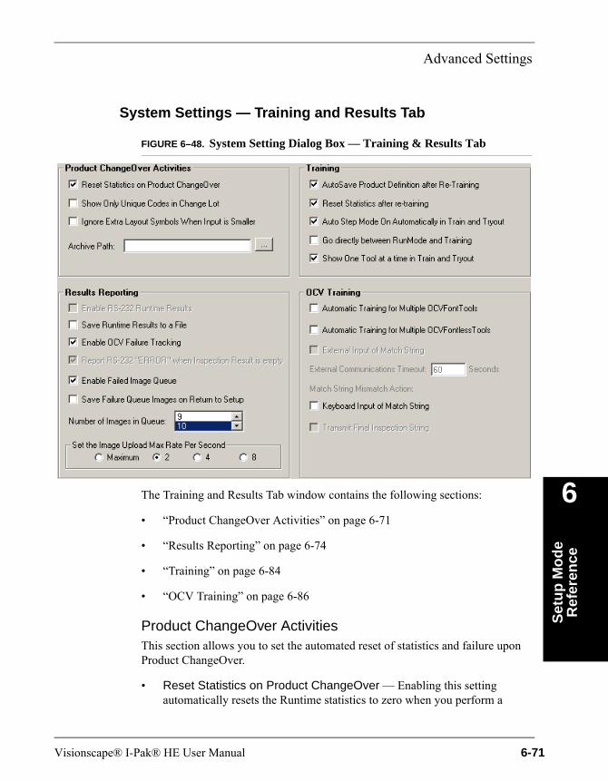
Advanced Settings
Set
up
Mo
de
Ref
eren
ce
6
System Settings — Training and Results Tab
FIGURE 6–48. System Setting Dialog Box — Training & Results Tab
The Training and Results Tab window contains the following sections:
• “Product ChangeOver Activities” on page 6-71
• “Results Reporting” on page 6-74
• “Training” on page 6-84
• “OCV Training” on page 6-86
Product ChangeOver ActivitiesThis section allows you to set the automated reset of statistics and failure upon Product ChangeOver.
• Reset Statistics on Product ChangeOver — Enabling this setting automatically resets the Runtime statistics to zero when you perform a
Visionscape® I-Pak® HE User Manual 6-71
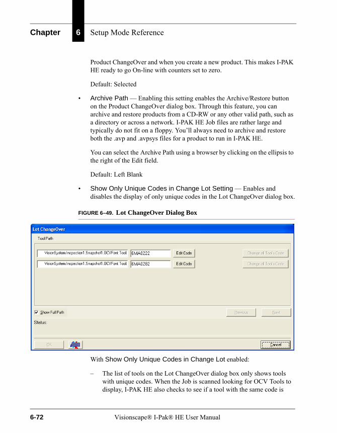
Chapter 6 Setup Mode Reference
Product ChangeOver and when you create a new product. This makes I-PAK HE ready to go On-line with counters set to zero.
Default: Selected
• Archive Path — Enabling this setting enables the Archive/Restore button on the Product ChangeOver dialog box. Through this feature, you can archive and restore products from a CD-RW or any other valid path, such as a directory or across a network. I-PAK HE Job files are rather large and typically do not fit on a floppy. You’ll always need to archive and restore both the .avp and .avpsys files for a product to run in I-PAK HE.
You can select the Archive Path using a browser by clicking on the ellipsis to the right of the Edit field.
Default: Left Blank
• Show Only Unique Codes in Change Lot Setting — Enables and disables the display of only unique codes in the Lot ChangeOver dialog box.
FIGURE 6–49. Lot ChangeOver Dialog Box
With Show Only Unique Codes in Change Lot enabled:
– The list of tools on the Lot ChangeOver dialog box only shows tools with unique codes. When the Job is scanned looking for OCV Tools to display, I-PAK HE also checks to see if a tool with the same code is
6-72 Visionscape® I-Pak® HE User Manual
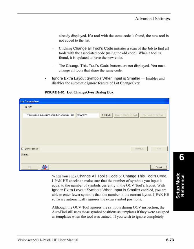
Advanced Settings
Set
up
Mo
de
Ref
eren
ce
6
already displayed. If a tool with the same code is found, the new tool is not added to the list.
– Clicking Change all Tool’s Code initiates a scan of the Job to find all tools with the associated code (using the old code). When a tool is found, it is updated to have the new code.
– The Change This Tool’s Code buttons are not displayed. You must change all tools that share the same code.
• Ignore Extra Layout Symbols When Input is Smaller — Enables and disables the automatic ignore feature of Lot ChangeOver.
FIGURE 6–50. Lot ChangeOver Dialog Box
When you click Change All Tool’s Code or Change This Tool’s Code, I-PAK HE checks to make sure that the number of symbols you input is equal to the number of symbols currently in the OCV Tool’s layout. With Ignore Extra Layout Symbols When Input is Smaller enabled, you are able to enter fewer symbols than the number in the current layout. I-PAK HE software automatically ignores the extra symbol positions.
Although the OCV Tool ignores the symbols during OCV inspection, the AutoFind still uses those symbol positions as templates if they were assigned as templates when the tool was trained. If you wish to ignore completely
Visionscape® I-Pak® HE User Manual 6-73
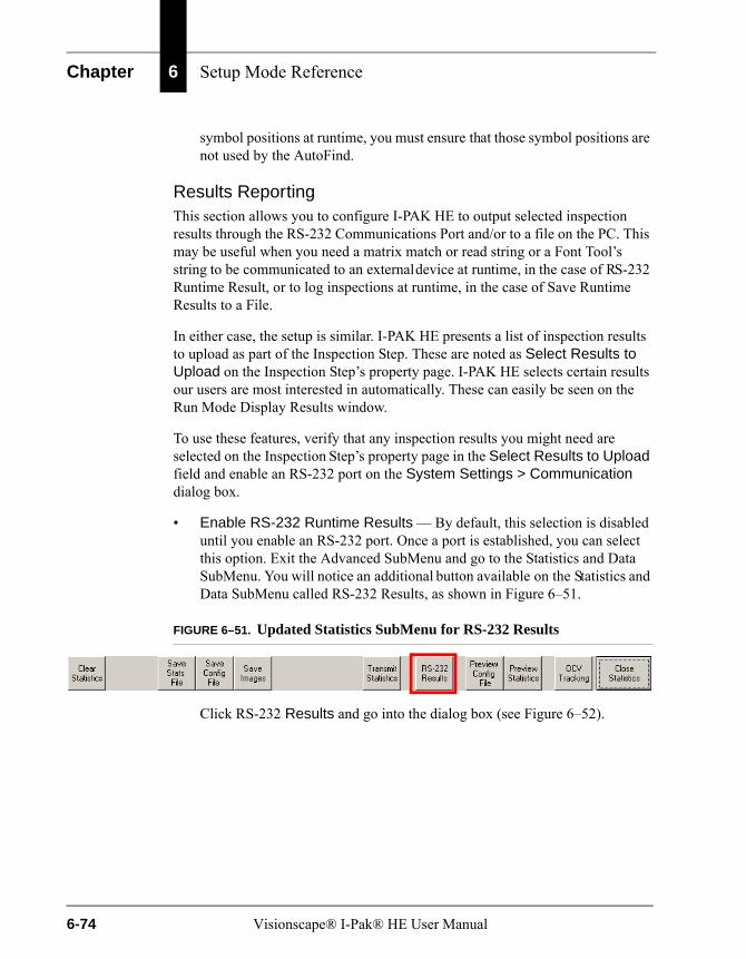
Chapter 6 Setup Mode Reference
symbol positions at runtime, you must ensure that those symbol positions are not used by the AutoFind.
Results ReportingThis section allows you to configure I-PAK HE to output selected inspection results through the RS-232 Communications Port and/or to a file on the PC. This may be useful when you need a matrix match or read string or a Font Tool’s string to be communicated to an external device at runtime, in the case of RS-232 Runtime Result, or to log inspections at runtime, in the case of Save Runtime Results to a File.
In either case, the setup is similar. I-PAK HE presents a list of inspection results to upload as part of the Inspection Step. These are noted as Select Results to Upload on the Inspection Step’s property page. I-PAK HE selects certain results our users are most interested in automatically. These can easily be seen on the Run Mode Display Results window.
To use these features, verify that any inspection results you might need are selected on the Inspection Step’s property page in the Select Results to Upload field and enable an RS-232 port on the System Settings > Communication dialog box.
• Enable RS-232 Runtime Results — By default, this selection is disabled until you enable an RS-232 port. Once a port is established, you can select this option. Exit the Advanced SubMenu and go to the Statistics and Data SubMenu. You will notice an additional button available on the Statistics and Data SubMenu called RS-232 Results, as shown in Figure 6–51.
FIGURE 6–51. Updated Statistics SubMenu for RS-232 Results
Click RS-232 Results and go into the dialog box (see Figure 6–52).
6-74 Visionscape® I-Pak® HE User Manual
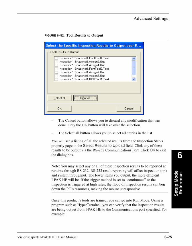
Advanced Settings
Set
up
Mo
de
Ref
eren
ce
6
FIGURE 6–52. Tool Results to Output
– The Cancel button allows you to discard any modification that was done. Only the OK button will take over the selection.
– The Select all button allows you to select all entries in the list.
You will see a listing of all the selected results from the Inspection Step’s property page in the Select Results to Upload field. Click any of these results to be output via the RS-232 Communications Port. Click OK to exit the dialog box.
Note: You may select any or all of these inspection results to be reported at runtime through RS-232. RS-232 result reporting will affect inspection time and system throughput. The fewer items you output, the more efficient I-PAK HE will be. If the trigger method is set to “continuous” or the inspection is triggered at high rates, the flood of inspection results can bog down the PC’s resources, making the mouse unresponsive.
Once this product’s tools are trained, you can go into Run Mode. Using a program such as HyperTerminal, you can verify that the inspection results are being output from I-PAK HE to the Communications port specified. For example:
Visionscape® I-Pak® HE User Manual 6-75
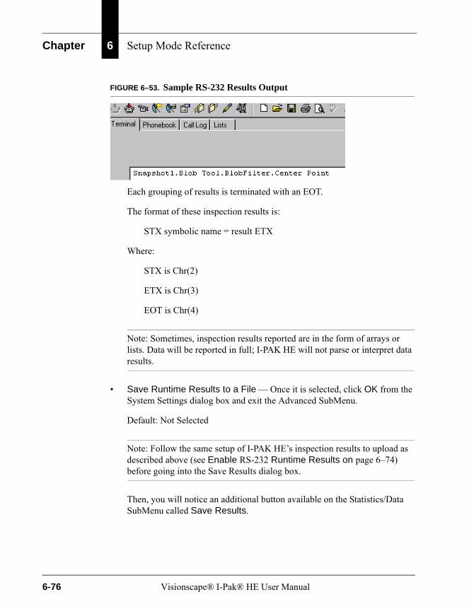
Chapter 6 Setup Mode Reference
FIGURE 6–53. Sample RS-232 Results Output
Each grouping of results is terminated with an EOT.
The format of these inspection results is:
STX symbolic name = result ETX
Where:
STX is Chr(2)
ETX is Chr(3)
EOT is Chr(4)
Note: Sometimes, inspection results reported are in the form of arrays or lists. Data will be reported in full; I-PAK HE will not parse or interpret data results.
• Save Runtime Results to a File — Once it is selected, click OK from the System Settings dialog box and exit the Advanced SubMenu.
Default: Not Selected
Note: Follow the same setup of I-PAK HE’s inspection results to upload as described above (see Enable RS-232 Runtime Results on page 6–74) before going into the Save Results dialog box.
Then, you will notice an additional button available on the Statistics/Data SubMenu called Save Results.
6-76 Visionscape® I-Pak® HE User Manual
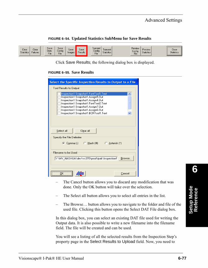
Advanced Settings
Set
up
Mo
de
Ref
eren
ce
6
FIGURE 6–54. Updated Statistics SubMenu for Save Results
Click Save Results; the following dialog box is displayed.
FIGURE 6–55. Save Results
– The Cancel button allows you to discard any modification that was done. Only the OK button will take over the selection.
– The Select all button allows you to select all entries in the list.
– The Browse… button allows you to navigate to the folder and file of the used file. Clicking this button opens the Select DAT File dialog box.
In this dialog box, you can select an existing DAT file used for writing the Output data. It is also possible to write a new filename into the filename field. The file will be created and can be used.
You will see a listing of all the selected results from the Inspection Step’s property page in the Select Results to Upload field. Now, you need to
Visionscape® I-Pak® HE User Manual 6-77
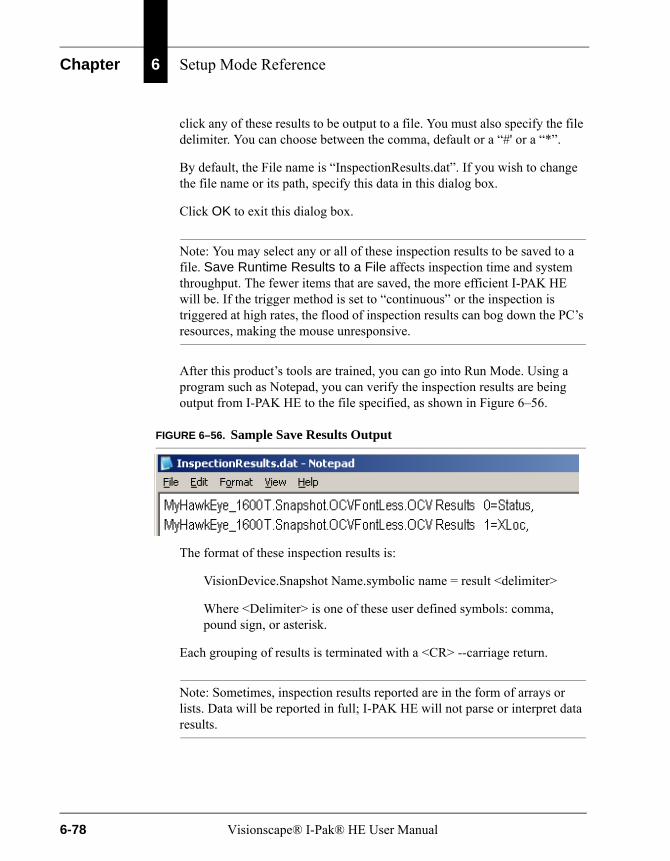
Chapter 6 Setup Mode Reference
click any of these results to be output to a file. You must also specify the file delimiter. You can choose between the comma, default or a “#' or a “*”.
By default, the File name is “InspectionResults.dat”. If you wish to change the file name or its path, specify this data in this dialog box.
Click OK to exit this dialog box.
Note: You may select any or all of these inspection results to be saved to a file. Save Runtime Results to a File affects inspection time and system throughput. The fewer items that are saved, the more efficient I-PAK HE will be. If the trigger method is set to “continuous” or the inspection is triggered at high rates, the flood of inspection results can bog down the PC’s resources, making the mouse unresponsive.
After this product’s tools are trained, you can go into Run Mode. Using a program such as Notepad, you can verify the inspection results are being output from I-PAK HE to the file specified, as shown in Figure 6–56.
FIGURE 6–56. Sample Save Results Output
The format of these inspection results is:
VisionDevice.Snapshot Name.symbolic name = result <delimiter>
Where <Delimiter> is one of these user defined symbols: comma, pound sign, or asterisk.
Each grouping of results is terminated with a <CR> --carriage return.
Note: Sometimes, inspection results reported are in the form of arrays or lists. Data will be reported in full; I-PAK HE will not parse or interpret data results.
6-78 Visionscape® I-Pak® HE User Manual
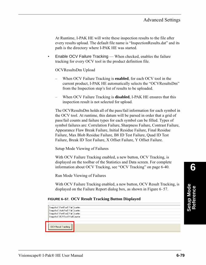
Advanced Settings
Set
up
Mo
de
Ref
eren
ce
6
At Runtime, I-PAK HE will write these inspection results to the file after every results upload. The default file name is “InspectionResults.dat” and its path is the directory where I-PAK HE was started.
• Enable OCV Failure Tracking — When checked, enables the failure tracking for every OCV tool in the product definition file.
OCVResultsDm Upload
– When OCV Failure Tracking is enabled, for each OCV tool in the current product, I-PAK HE automatically selects the “OCVResultsDm” from the Inspection step’s list of results to be uploaded.
– When OCV Failure Tracking is disabled, I-PAK HE ensures that this inspection result is not selected for upload.
The OCVResultsDm holds all of the pass/fail information for each symbol in the OCV tool. At runtime, this datum will be parsed in order that a grid of pass/fail counts and failure types for each symbol can be filled. Types of symbol failures are: Correlation Failure, Sharpness Failure, Contrast Failure, Appearance Flaw Break Failure, Initial Residue Failure, Final Residue Failure, Max Blob Residue Failure, B8 ID Test Failure, Quad ID Test Failure, Break ID Test Failure, X Offset Failure, Y Offset Failure.
Setup Mode Viewing of Failures
With OCV Failure Tracking enabled, a new button, OCV Tracking, is displayed on the toolbar of the Statistics and Data screen. For complete information about OCV Tracking, see “OCV Tracking” on page 6-40.
Run Mode Viewing of Failures
With OCV Failure Tracking enabled, a new button, OCV Result Tracking, is displayed on the Failure Report dialog box, as shown in Figure 6–57.
FIGURE 6–57. OCV Result Tracking Button Displayed
Visionscape® I-Pak® HE User Manual 6-79
Chapter 6 Setup Mode Reference
When you click this button, the OCV Failure Tracking dialog box is displayed. This dialog box is the same as the Setup Mode dialog box except that it does not allow saving the data to a file (see Figure 6–24, “OCV Failure Tracking Dialog Box,” on page 6-41).
Loading New Jobs
When a new Job is loaded and OCV Failure Tracking is enabled, any existing Individual Results dialog boxes are removed from I-PAK HE. Then, the Job is scanned for OCV tools. For each OCV tool found, the OCVResultsDm is selected for upload and an Individual Results dialog box is created for the tool. The OCV Tracking screen is updated to reflect the OCV tools that are in the currently loaded Job.
• Report RS-232 ERROR when inspection Result is Empty — I-PAK HE has a System Setting to enable/disable the RS-232 Error codes from being sent during any tool failure. By default, this setting is enabled and allows I-PAK HE to report “ERROR” when the RS-232 result data is empty. You can disable this setting so that when the data is empty, I-PAK HE does not report anything. This only affects data sent out RS-232, and not what you see on the I-PAK HE display.
• Enable Failed Image Queue — When you check Enable Failed Image Queue, the Failed Image Queue button on the Camera View becomes active. All images from inspections that fail that can be saved are saved to the Failed Image Queue. The Failed Image Queue is lossy. For more information, see Show/Hide Failed Image Queue on page 7–3. To save every failed image (lossless), see “Save Images” on page 6-33.
• Save Failure Queue Images on Return to Setup — Enables and disables (default) the saving of the failure queue images when you return to Setup Mode.
You can view a queue of the last 1 to 20 failures per Smart Camera. When the user-settable maximum number of images is reached, a new failed image overwrites the image in the first image frame.
Only images that are successfully uploaded to the I-PAK HE interface from the Smart Camera are entered into the queue. Not all images get uploaded to the I-PAK HE interface to avoid compromising inspection throughput. For that reason, when failures occur in rapid succession, the failed images may not be entered into the queue.
6-80 Visionscape® I-Pak® HE User Manual

Advanced Settings
Set
up
Mo
de
Ref
eren
ce
6
• Number of Images In Queue — Specifies the number of failed images to save in the Failed Image Queue.
Default: 10 failed imagesRange: 1 to 20 failed images
Using the Failed Image Queue at RuntimeFailed Image Queue Button
The camera view contains the Failed Image Queue button, as shown in Figure 6–58.
FIGURE 6–58. Failed Image Queue Button
After you click Failed Image Queue, the display changes so that you can cycle through the failed images, as shown in Figure 6–59.
FIGURE 6–59. Screen to Cycle Through Failed Images
Clicking the right and left arrow buttons cycles the display through the available image frames. If no failed image has been assigned to a frame, that
Visionscape® I-Pak® HE User Manual 6-81
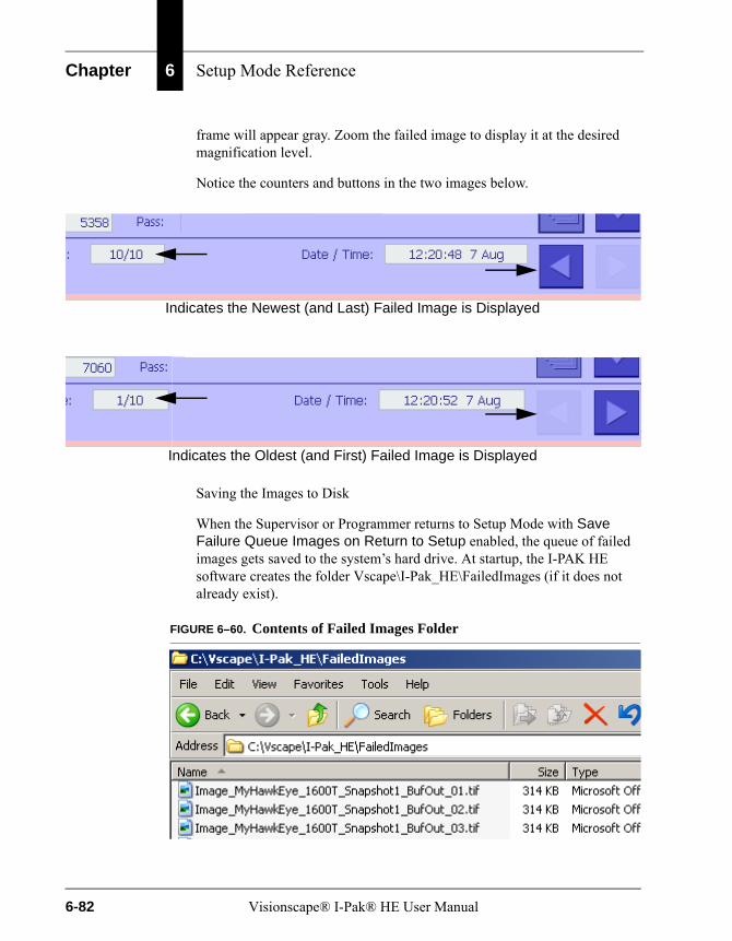
Chapter 6 Setup Mode Reference
frame will appear gray. Zoom the failed image to display it at the desired magnification level.
Notice the counters and buttons in the two images below.
Saving the Images to Disk
When the Supervisor or Programmer returns to Setup Mode with Save Failure Queue Images on Return to Setup enabled, the queue of failed images gets saved to the system’s hard drive. At startup, the I-PAK HE software creates the folder Vscape\I-Pak_HE\FailedImages (if it does not already exist).
FIGURE 6–60. Contents of Failed Images Folder
Indicates the Newest (and Last) Failed Image is Displayed
Indicates the Oldest (and First) Failed Image is Displayed
6-82 Visionscape® I-Pak® HE User Manual

Advanced Settings
Set
up
Mo
de
Ref
eren
ce
6
When failed images are written to the hard disk, I-PAK HE overwrites any images that may already be in the I-PAK HE\FailedImages folder. It is the Supervisor’s (or Programmer’s) responsibility to save any images that might be needed for debugging or other purposes at a later time.
Image Upload Maximum Rate
To better utilize I-PAK HE’s CPU usage, you can set the Advanced Settings > System Settings > Training and Results > Set the Image Upload Max Rate Per Second. This setting is for the number of images transferred back to the PC per second.
At runtime, the inspected images get transferred back from the Smart Camera to the PC and are displayed on the “Camera” views on the I-PAK HE Run Mode interface. In earlier software versions from Microscan, we tried to display the maximum number of images possible. In some cases, however, especially on slower PCs, this flood of images can bog down the PC’s CPU, and may max out the CPU, making the mouse unresponsive. For this reason, we limit the number of images that are displayed per second.
By default, this is set to 4. You can decrease it to 2, or increase it to 4, 8 or Maximum.
– Increasing this setting enables more images to come back to the PC. But, as you increase this setting, you increase CPU usage.
– Decreasing this setting limits the number of images coming back to the PC. Therefore, you may not see “every image” that the Smart Camera processes.
Setting a small number here will result in a “sluggish” update of the Smart Camera’s images. Setting a higher number will result in a more “lively” update of runtime images. Microscan can only suggest settings for this field. You need to run your production line at line speeds and judge the best setting for yourself.
Note: You can reliably trust the Smart Camera’s processing - if the Smart Camera reports a Pass signal through the IO, then the part is good. Likewise, a Fail IO signal should cause the part to be rejected. You may not see all these failed images if you are running at high production rates (parts per minute) and depending on the Set the Image Upload Max Rate Per Second setting.
Visionscape® I-Pak® HE User Manual 6-83
Chapter 6 Setup Mode Reference
Note: When using a Job that is inspecting “frozen” images, or images from disk, set this to “Maximum” for the best runtime user interface response.
TrainingThis section allows you to set the automated saving of the product definition every time the Job is retrained.
• AutoSave Product Definition after Re-Training — Enabling this setting automatically saves the product definition after each retraining of the Job. This prevents changes from being lost.
Default: Selected
• Reset Statistics after re-training — Enabling this setting automatically resets the Runtime statistics to zero when you perform a Product ChangeOver and when you create a new product. This makes I-PAK HE ready to go On-line with counters set to zero.
Default: Selected
• AutoStep Mode on Automatically in Train and Tryout — Enabling this setting sets the Train and Tryout menu’s AutoStep (Wizard) Mode on. Some users may want to disable this AutoStep Mode option so they can just go right to the tools they wish to retrain or adjust.
Default: Selected
• Go directly between RunMode and Training — Enabling this setting brings you right into the Train and Tryout menus directly from Run Mode. You will bypass the main Setup Menu. You may find this useful if you usually come out of Run Mode and go directly into Train and Tryout. This saves a mouse click.
Default: Selected
6-84 Visionscape® I-Pak® HE User Manual

Advanced Settings
Set
up
Mo
de
Ref
eren
ce
6
• Show One Tool at a time in Train and Tryout — When in Train and Tryout, and this option is turned on, you will only be able to adjust the ROI of the step that’s selected currently in the step list; all others ROIs will be hidden. This is a useful feature when there are many ROIs in the inspection, and you have a hard time selecting the specific ROI s/he needs. Tools can be selected using the list on the left hand side of the screen. See Figure 6–61.
FIGURE 6–61. Training Screen Showing One Tool at a Time
When disabled, the tool graphics for all tools will be displayed (unless in AutoStep mode) in the buffer on the Train and Tryout screen. Tools can be selected using the list on the left hand side of the screen or by clicking on the tool graphics for the tool. See Figure 6–62.
Visionscape® I-Pak® HE User Manual 6-85
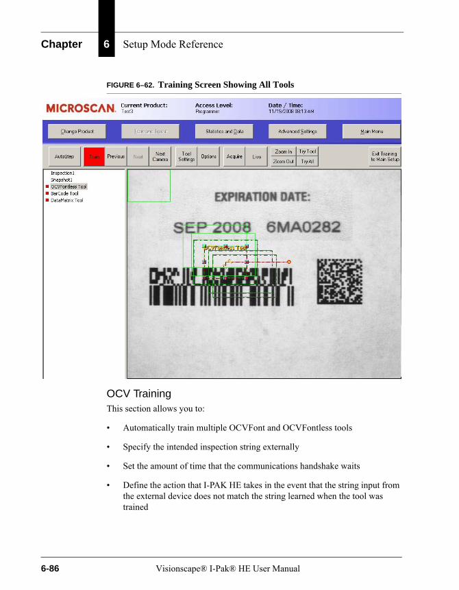
Chapter 6 Setup Mode Reference
FIGURE 6–62. Training Screen Showing All Tools
OCV TrainingThis section allows you to:
• Automatically train multiple OCVFont and OCVFontless tools
• Specify the intended inspection string externally
• Set the amount of time that the communications handshake waits
• Define the action that I-PAK HE takes in the event that the string input from the external device does not match the string learned when the tool was trained
6-86 Visionscape® I-Pak® HE User Manual
Advanced Settings
Set
up
Mo
de
Ref
eren
ce
6
• Specify the intended inspection string for an OCVFont Tool or OCVRuntimeTool
• Send the final inspection string out after training an OCVFont Tool or OCVRuntimeTool
Description of OCV Training Section Settings
• Automatic Training for Multiple OCVFontTools — Allows a Programmer to quickly train multiple OCVFont Tools, typically, where each tool uses the same OCVFont and has the same layout. Automatic training requires that an image be available for training and that the Programmer train the first tool in the group of multiple tools.
Default: Disabled (every OCVFont Tool must be trained manually)
With Automatic Training for Multiple OCVFontTools enabled, when an OCVFont Tool is trained, the “Disapprove Substitute Approve” screen is displayed. When the layout is approved, the I-PAK HE software scans the other tools in the snapshot looking for OCVFont Tools with the same name or same match criteria as the OCVFont Tool that was just approved.
Note: Match criteria is defined as a string of characters that comes after a “ - “ (space dash space) separator in the tool name. For example, if a tool is named “OCVFont Tool - Date Code”, the match criteria is “Date Code”. After you train the tool and click Approve, I-PAK HE scans for and trains any OCVFont Tools in the snapshot that have the same match criteria (you must use the “ - ” notation to separate the tool name from the match criteria). If there is no match criteria in the tool name (no “ - ”), I-PAK HE uses the entire tool name when searching for OCVFont tools to train.
• Automatic Training for Multiple OCVFontless Tools — Allows a Programmer to quickly train multiple OCVFontless Tools. Automatic training requires that an image be available for training and that the Programmer train the first tool in the group of multiple tools
Default: Disabled (every OCVFontless Tool must be trained manually)
With Automatic Training for Multiple OCVFontless Tools enabled, when an OCVFontless Tool is trained, the I-PAK HE software scans the other tools in the snapshot looking for OCVFontless Tools with the same name or same match criteria as the OCVFontless Tool that was just trained.
Visionscape® I-Pak® HE User Manual 6-87
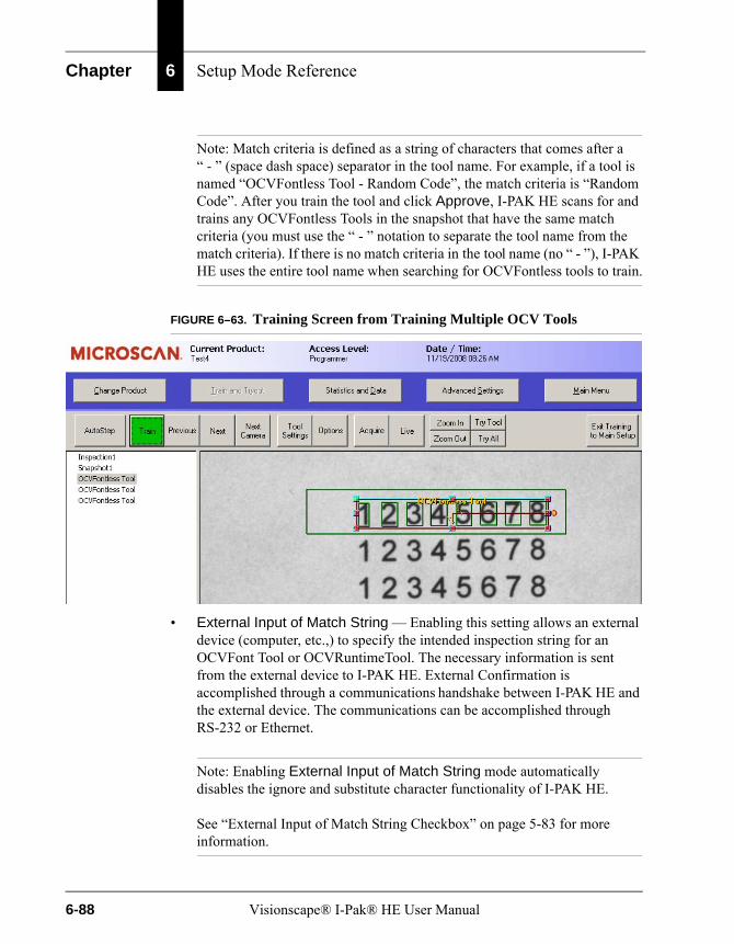
Chapter 6 Setup Mode Reference
Note: Match criteria is defined as a string of characters that comes after a “ - ” (space dash space) separator in the tool name. For example, if a tool is named “OCVFontless Tool - Random Code”, the match criteria is “Random Code”. After you train the tool and click Approve, I-PAK HE scans for and trains any OCVFontless Tools in the snapshot that have the same match criteria (you must use the “ - ” notation to separate the tool name from the match criteria). If there is no match criteria in the tool name (no “ - ”), I-PAK HE uses the entire tool name when searching for OCVFontless tools to train.
FIGURE 6–63. Training Screen from Training Multiple OCV Tools
• External Input of Match String — Enabling this setting allows an external device (computer, etc.,) to specify the intended inspection string for an OCVFont Tool or OCVRuntimeTool. The necessary information is sent from the external device to I-PAK HE. External Confirmation is accomplished through a communications handshake between I-PAK HE and the external device. The communications can be accomplished through RS-232 or Ethernet.
Note: Enabling External Input of Match String mode automatically disables the ignore and substitute character functionality of I-PAK HE.
See “External Input of Match String Checkbox” on page 5-83 for more information.
6-88 Visionscape® I-Pak® HE User Manual

Advanced Settings
Set
up
Mo
de
Ref
eren
ce
6
• External Communications Timeout — Setting this field determines the amount of time that the communications handshake waits.
• Match String Mismatch Action — Defines the action that I-PAK HE takes in the event that the string input from the external device does not match the string learned when the tool was trained. The possible selections and their meaning are:
– Use Input String — (Default) I-PAK HE uses the input string as the inspection string.
– Use Learned String — I-PAK HE ignores the input string and set the string found during training as the inspection string.
– Retry by Learning — I-PAK HE forces you to retrain the tool and allows the string to be entered again.
– Retry by Input — I-PAK HE allows the string to be entered again.
Note: The Match String Mismatch Action selected is applied to any OCVFont Tool or OCVRuntimeTool in the current Job.
Refer to “Match String Mismatch Action” on page 5-84 for more information.
• Keyboard Input of Match String — Enabling this setting allows you to specify the intended inspection string for an OCVFont Tool or OCVRuntimeTool. This is accomplished by displaying an input box into which you can type the necessary information.
Note: Refer to “Keyboard Input of Match String” on page 5-78 for more information.
• Transmit Final Inspection String — Enabling this setting allows I-PAK HE to send out the final inspection string after training an OCVFont Tool or OCVRuntimeTool.
Note: Refer to “Transmit Final Inspection String” on page 5-88 for more information.
Visionscape® I-Pak® HE User Manual 6-89
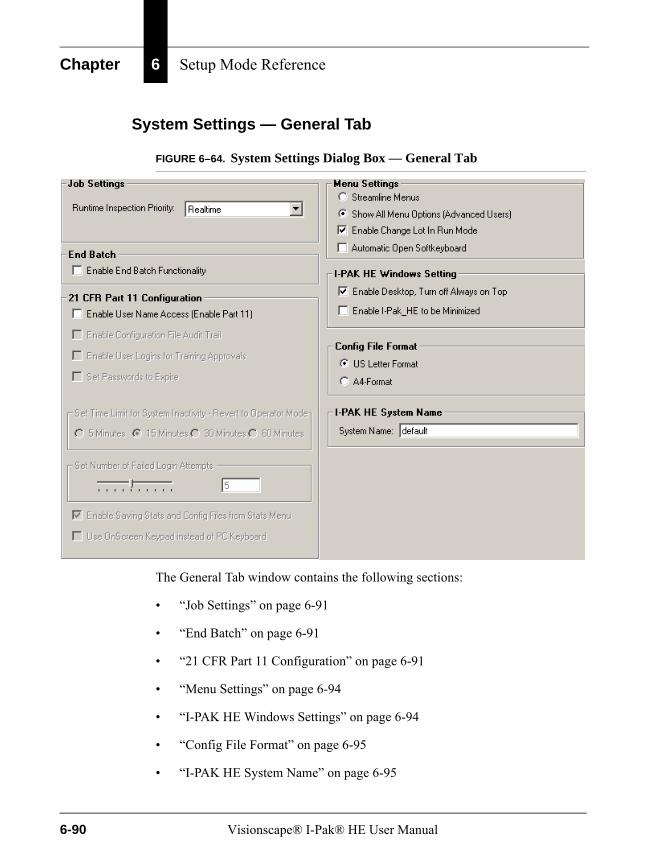
Chapter 6 Setup Mode Reference
System Settings — General Tab
FIGURE 6–64. System Settings Dialog Box — General Tab
The General Tab window contains the following sections:
• “Job Settings” on page 6-91
• “End Batch” on page 6-91
• “21 CFR Part 11 Configuration” on page 6-91
• “Menu Settings” on page 6-94
• “I-PAK HE Windows Settings” on page 6-94
• “Config File Format” on page 6-95
• “I-PAK HE System Name” on page 6-95
6-90 Visionscape® I-Pak® HE User Manual

Advanced Settings
Set
up
Mo
de
Ref
eren
ce
6
Job SettingsThis section allows you to select or change Runtime Inspection Priority. This is the runtime priority of the current process. The options are Normal, High, and Realtime.
Note: You must have access rights to change the process setting.
End BatchEnable End Batch Functionality allows you to automatically save the read-only statistics file to the hard drive when you exit Run Mode. When Enable End Batch Functionality is enabled (disabled by default), I-PAK HE displays the “End this Batch?” dialog box:
• Click Yes to display the Save Statistics To a Data File As dialog box. Enter a file name and click Save. I-PAK HE saves the counters in the PC registry.
• Click No to simply enter Setup Mode.
21 CFR Part 11 ConfigurationThis section allows you to set the 21 CFR Part 11 compliance features for user access control (logins) and creating an audit trail. For complete information about 21 CFR Part 11, see Chapter 3.
• Enable User Name Access (Enable Part 11) — Enabling this setting disables the traditional Programmer and Supervisor modes and replaces it with the I-PAK Administrator mode. Then, an I-PAK Administrator defines valid users, their passwords and their security levels.
The I-PAK Administrator is your Configuration Manager. He or she is not a Programmer, not a Supervisor, and not an Operator.
I-PAK Administrator User Name: I-PakAdminI-PAK Administrator Password: 999999
The I-PAK Administrator must create the valid user accounts before users can begin using the feature.
Default: Off
• Enable Configuration File Audit Trail — When this setting is enabled, each time the Job definition file is saved to disk, a new read-only
Visionscape® I-Pak® HE User Manual 6-91

Chapter 6 Setup Mode Reference
configuration file is saved to the archive directory (i.e., C:\Vscape\I-Pak_HE\Jobs\ConfigurationArchives). This configuration file is marked with the user name, date and time. Old configuration files will not be overwritten. You can determine changes by looking at sequential configuration files. Names for the configuration files are the product name with a date/time identifier.
Default: Off
• Enable User Logins for Training Approvals — Enabling this option requires your user name/password login when training the following tools:
– Training a Font Tool or Runtime Font Tool.
– Entering a keyboard match string entry for a Data Matrix or barcode match.
Default: Off
As you train the tools in a Job, you are prompted to enter your I-PAK HE Part 11 user name and password for training any FontTool or Runtime Font Tool, and for the Data Matrix and Barcode Tools when in match mode.
Note: The System Setting for “Enable User Name Access” must be enabled.
Training a Font Tool or Runtime Font Tool: When training any font based Font Tool, as you click Train, you are prompted for your user name and password. When you have the system setting for the Font Tool’s “Keyboard Input of Match String” enabled, you are prompted for your user name and password before entering the Font Tool’s match string.
Training a Data Matrix or Barcode Tool in Match Mode:When training a Data Matrix Tool or Barcode Tool in AutoStep Mode, with Match String Enable of the tool selected, I-PAK HE automatically prompts you for your user name and password before entering the Data Matrix or Barcode Tool’s match string. I-PAK HE also prompts you for your user name and password when you click Train with a Data Matrix or Barcode Tool selected with Match String Enable selected. I-PAK HE will not prompt you for the login when just retraining a read mode Data Matrix or Barcode Tool.
6-92 Visionscape® I-Pak® HE User Manual

Advanced Settings
Set
up
Mo
de
Ref
eren
ce
6
In Part 11 mode, if Enable User Logins for Training Approvals is:
– On — Operators cannot change lot in Run Mode.
– Off — Operators can change lot in Run Mode.
• Set Passwords to Expire — Enabling this option makes your password expire after a certain specified time period (15, 30, 60 or 90 days). When this option is selected, a submenu is displayed where you can select the duration.
Default: Off
Note: System Setting > General > Enable User Name Access must also be enabled.
When this option is used, as you successfully exit Run Mode using your Part 11 login user name and password, I-PAK HE checks this user’s password and the current date and time to see if your password has expired. A pop-up message box is displayed if you need to reset your password.
You will not be penalized or lose your account if you do not reset your password. However, you will continue to see these message boxes every time you exit Run Mode or enter your user name and password.
• Set Time Limit for System Inactivity — Setting the time interval to 5, 15, 30 or 60 minutes causes the I-PAK HE system to revert back to the Operator access level after that period of System Inactivity. The default time interval is 15 minutes.
• Set Number of Failed Login Attempts — Setting the number of failed login attempts to a number between 1 and 10 causes the I-PAK HE system to suspend a user who has unsuccessfully tried to login X number of times in a row. Only an I-PAK Administrator can restore this suspended account. The default is 5.
• Enable Saving Stats and Config Files from Stats Menu — Enabling this option makes a more configurable I-PAK HE user interface. This setting enables and disables the buttons for Save Stats and Save Config Files, saving the Statistics and Configuration files, from the Statistics and Data submenus.
Visionscape® I-Pak® HE User Manual 6-93

Chapter 6 Setup Mode Reference
• Use OnScreen Keypad instead of PC Keyboard — Enabling this option causes I-PAK HE to display an OnScreen Keyboard for entering login and training approval user names and passwords.
Menu SettingsThis section allows you to streamline the menus.
• Streamline Menus — Presents a clean, less cluttered Operator interface.
• Show All Menu Options (Advanced Users) — (Default) Select this option to display the menus like they are presented in this user manual.
• Enable Change Lot in Run Mode — When checked, the Change Lot button is visible in Run Mode (meaning Change Lot is possible).
• Automatic Open Softkeyboard — When checked, the Softkeyboard is opened automatically if the selected dialog box requires data input. This is available only when I-PAK HE is running on a Touch panel PC.
I-PAK HE Windows SettingsThis section allows you to configure I-PAK HE to run with other programs on the PC.
• Enable I-PAK_HE to be Minimized — Allows the I-PAK HE user interface to be minimized while running. Inspections still occur and results are transferred back to the I-PAK HE interface.
Default: Disabled
Note: When you change these settings, you must restart the I-PAK HE interface, since this is a Windows call that goes into effect at start up of the interface.
• Enable Desktop — Allows you to show or hide the PC Desktop. When disabled, I-PAK HE will trap user keys like Ctrl-Esc and the PC’s Start button to prevent the Start menu from appearing, Alt-Tab to prevent the user from leaving the I-PAK HE interface, and Alt-Esc from displaying the TaskBar. I-PAK HE does not trap or disallow the Ctrl-Alt-Del sequence, as Microsoft recommends against such action as it would interfere with the PC’s security.
Default: Enabled
6-94 Visionscape® I-Pak® HE User Manual

Advanced Settings
Set
up
Mo
de
Ref
eren
ce
6
Config File FormatThis section allows you to configure the file format.
• US Letter Format — By default, the file format is set to US Letter (about 66 lines/page).
• A4 Format — Sets the file format to A4 Format (about 72 lines/page).
I-PAK HE System NameYou can name the I-PAK HE system, which is a useful feature when you have several I-PAK HE systems dumping Configuration files to a central PC, and you need a way to identify uniquely each I-PAK HE system.
Edit Tool SetThis is a Programmer level function.
Edit Tool Set allows the Programmer to add, delete, or edit all the tools in the current product Job definition in a tree-like structure, as shown in Figure 6–65. You can print the Tree View of your Job, and you can save the Tree View data of the Job to a file.
Note: Edit is intended to give the advanced Programmer a chance to tune an inspection. When inserting steps here, you should understand that not all parameters will be automatically set up for you as they are when you create a Job via the “Create Product” option.
Visionscape® I-Pak® HE User Manual 6-95
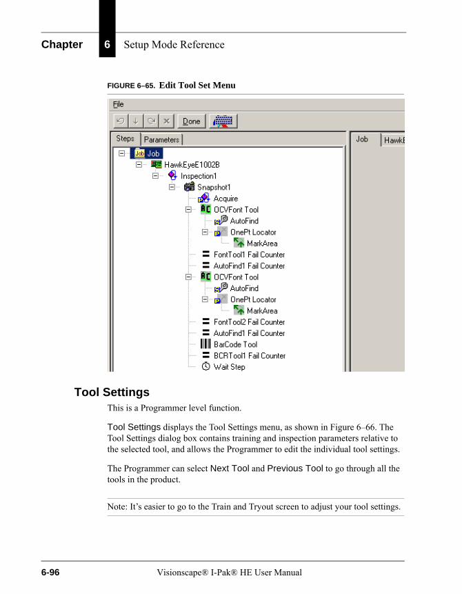
Chapter 6 Setup Mode Reference
FIGURE 6–65. Edit Tool Set Menu
Tool SettingsThis is a Programmer level function.
Tool Settings displays the Tool Settings menu, as shown in Figure 6–66. The Tool Settings dialog box contains training and inspection parameters relative to the selected tool, and allows the Programmer to edit the individual tool settings.
The Programmer can select Next Tool and Previous Tool to go through all the tools in the product.
Note: It’s easier to go to the Train and Tryout screen to adjust your tool settings.
6-96 Visionscape® I-Pak® HE User Manual
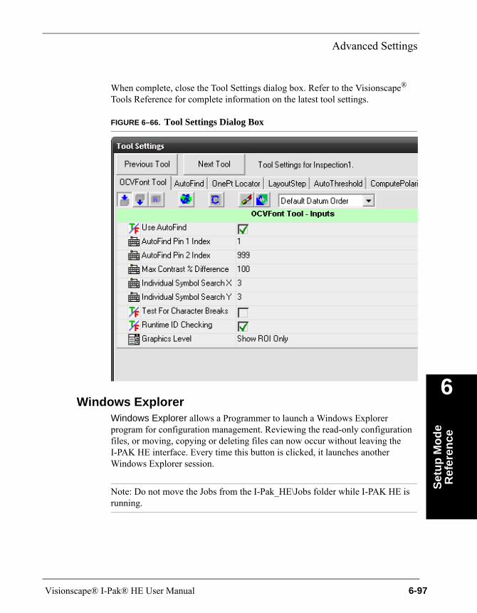
Advanced Settings
Set
up
Mo
de
Ref
eren
ce
6
When complete, close the Tool Settings dialog box. Refer to the Visionscape® Tools Reference for complete information on the latest tool settings.
FIGURE 6–66. Tool Settings Dialog Box
Windows ExplorerWindows Explorer allows a Programmer to launch a Windows Explorer program for configuration management. Reviewing the read-only configuration files, or moving, copying or deleting files can now occur without leaving the I-PAK HE interface. Every time this button is clicked, it launches another Windows Explorer session.
Note: Do not move the Jobs from the I-Pak_HE\Jobs folder while I-PAK HE is running.
Visionscape® I-Pak® HE User Manual 6-97
Chapter 6 Setup Mode Reference
Close AdvancedThis is a Programmer level function.
Close Advanced quits the Advanced Settings Toolbar and returns you to the main I-PAK HE Setup Mode window.
Run ModeUse the Run Mode button when you want to leave Setup Mode after performing a Product ChangeOver, configuring or retraining a Job, and return to Run Mode with your access level reset to Operator.
At this time, the inspection Job is downloaded to the Smart Camera(s). Windows Registry information is updated with the name of this Job. This provides recovery in the event of a power loss, and enables I-PAK HE to recover to Run Mode running this last Product. Run Mode can be accessed by any user: I-PAK Administrator, Programmer, Supervisor or Operator.
All tools must be trained before you can run your product in Run Mode. The Run Mode button is grayed out until all tools in the current Job are trained.
Troubleshooting
Memory Limitations on the HawkEye 1600TThere are limits to the size of Job that can be run on the HawkEye 1600T. In general, AVP files that are larger than 2.7M to 3M will not fit in the HawkEye’s available memory. In some cases, Jobs that are smaller than this may run out of memory as well. Specifically, Jobs that use several IntelliFind™ tools with large templates, or Jobs with many OCV tools and/or large font libraries may run out of memory. Keep this in mind when building your inspections.
Shutting Down I-PAK HEThe I-PAK HE program should be shut down before disconnecting, connecting or reconfiguring the Smart Cameras. If I-PAK HE is running when the cameras are disconnected and reconnected, Setup Mode may not properly display images, in which case, it will be necessary to shut down the I-PAK HE application and then restart it.
6-98 Visionscape® I-Pak® HE User Manual
7
Ru
n M
od
e R
efer
ence
7
CHAPTER 7 Run Mode Reference
This chapter describes the Visionscape® I-PAK® HE Run Mode functionality.
OverviewBy default, when I-PAK HE starts up, the Run Mode window is displayed, as shown in Figure 7–1. This is the main user interface for the I-PAK HE Operator, and allows viewing of images, inspection counts, and results for the currently running product.
Note: You must let I-PAK HE fully download your Job and assert the Run Mode output before giving it triggers.
The first time I-PAK HE starts up, you will be prompted to select a Smart Camera, and a sample job will be created and downloaded to that Smart Camera, as described in “Running I-PAK HE for the First Time” on page 1-11. Every time I-PAK HE is subsequently launched, it will load and download the Job that was running the last time I-PAK HE was shut down. All important I-PAK HE data is
NoticeIt is critical that you use a UPS with your I-PAK HE to ensure your inspection counts are retained. Inspection counts are written to the system registry on the way out of Run Mode. In the event of power loss, a UPS ensures that your counts are written to the registry and that I-PAK HE and Windows shutdown gracefully.
Visionscape® I-Pak® HE User Manual 7-1
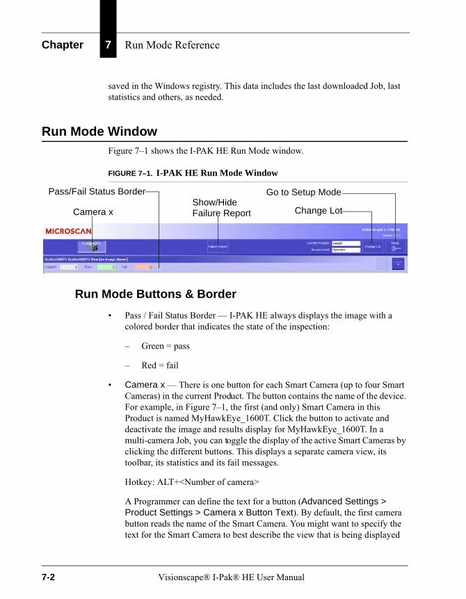
Chapter 7 Run Mode Reference
saved in the Windows registry. This data includes the last downloaded Job, last statistics and others, as needed.
Run Mode WindowFigure 7–1 shows the I-PAK HE Run Mode window.
FIGURE 7–1. I-PAK HE Run Mode Window
Run Mode Buttons & Border
• Pass / Fail Status Border — I-PAK HE always displays the image with a colored border that indicates the state of the inspection:
– Green = pass
– Red = fail
• Camera x — There is one button for each Smart Camera (up to four Smart Cameras) in the current Product. The button contains the name of the device. For example, in Figure 7–1, the first (and only) Smart Camera in this Product is named MyHawkEye_1600T. Click the button to activate and deactivate the image and results display for MyHawkEye_1600T. In a multi-camera Job, you can toggle the display of the active Smart Cameras by clicking the different buttons. This displays a separate camera view, its toolbar, its statistics and its fail messages.
Hotkey: ALT+<Number of camera>
A Programmer can define the text for a button (Advanced Settings > Product Settings > Camera x Button Text). By default, the first camera button reads the name of the Smart Camera. You might want to specify the text for the Smart Camera to best describe the view that is being displayed
Camera xShow/HideFailure Report Change Lot
Go to Setup ModePass/Fail Status Border
7-2 Visionscape® I-Pak® HE User Manual
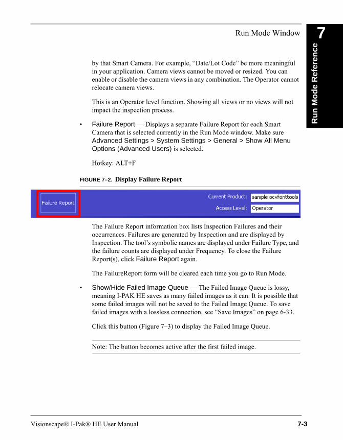
Run Mode Window
Ru
n M
od
e R
efer
ence
7
by that Smart Camera. For example, “Date/Lot Code” be more meaningful in your application. Camera views cannot be moved or resized. You can enable or disable the camera views in any combination. The Operator cannot relocate camera views.
This is an Operator level function. Showing all views or no views will not impact the inspection process.
• Failure Report — Displays a separate Failure Report for each Smart Camera that is selected currently in the Run Mode window. Make sure Advanced Settings > System Settings > General > Show All Menu Options (Advanced Users) is selected.
Hotkey: ALT+F
FIGURE 7–2. Display Failure Report
The Failure Report information box lists Inspection Failures and their occurrences. Failures are generated by Inspection and are displayed by Inspection. The tool’s symbolic names are displayed under Failure Type, and the failure counts are displayed under Frequency. To close the Failure Report(s), click Failure Report again.
The FailureReport form will be cleared each time you go to Run Mode.
• Show/Hide Failed Image Queue — The Failed Image Queue is lossy, meaning I-PAK HE saves as many failed images as it can. It is possible that some failed images will not be saved to the Failed Image Queue. To save failed images with a lossless connection, see “Save Images” on page 6-33.
Click this button (Figure 7–3) to display the Failed Image Queue.
Note: The button becomes active after the first failed image.
Visionscape® I-Pak® HE User Manual 7-3
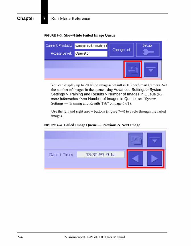
Chapter 7 Run Mode Reference
FIGURE 7–3. Show/Hide Failed Image Queue
You can display up to 20 failed images (default is 10) per Smart Camera. Set the number of images in the queue using Advanced Settings > System Settings > Training and Results > Number of Images in Queue (for more information about Number of Images in Queue, see “System Settings — Training and Results Tab” on page 6-71).
Use the left and right arrow buttons (Figure 7–4) to cycle through the failed images.
FIGURE 7–4. Failed Image Queue — Previous & Next Image
7-4 Visionscape® I-Pak® HE User Manual

Run Mode Window
Ru
n M
od
e R
efer
ence
7
Notice the counters and arrow buttons in the two images below:
When the queue reaches the maximum number of images, and an additional failure occurs, the first image in the queue gets overwritten by the new failed image.
Click Show/Hide Failed Image Queue to return to the regular I-PAK HE Camera display. Click the Zoom buttons to bring the displayed failed image to the desired magnification level.
• Reset Interval Counters — Click this button (Figure 7–5) to reset the interval counters to zero.
FIGURE 7–5. Reset Interval Counters
Indicates the Newest (and Last) Failed Image is Displayed
Indicates the Oldest (and First) Failed Image is Displayed
Visionscape® I-Pak® HE User Manual 7-5
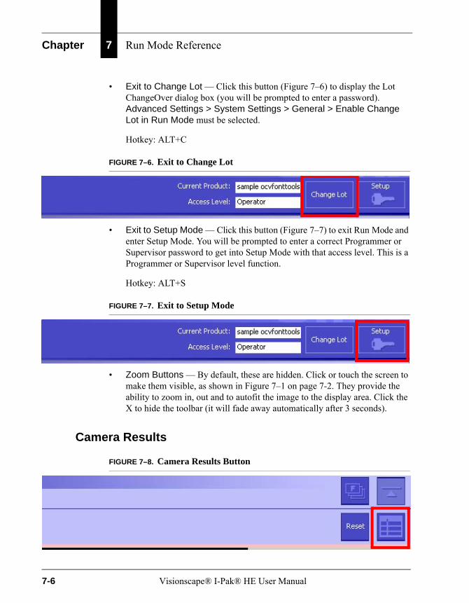
Chapter 7 Run Mode Reference
• Exit to Change Lot — Click this button (Figure 7–6) to display the Lot ChangeOver dialog box (you will be prompted to enter a password). Advanced Settings > System Settings > General > Enable Change Lot in Run Mode must be selected.
Hotkey: ALT+C
FIGURE 7–6. Exit to Change Lot
• Exit to Setup Mode — Click this button (Figure 7–7) to exit Run Mode and enter Setup Mode. You will be prompted to enter a correct Programmer or Supervisor password to get into Setup Mode with that access level. This is a Programmer or Supervisor level function.
Hotkey: ALT+S
FIGURE 7–7. Exit to Setup Mode
• Zoom Buttons — By default, these are hidden. Click or touch the screen to make them visible, as shown in Figure 7–1 on page 7-2. They provide the ability to zoom in, out and to autofit the image to the display area. Click the X to hide the toolbar (it will fade away automatically after 3 seconds).
Camera Results
FIGURE 7–8. Camera Results Button
7-6 Visionscape® I-Pak® HE User Manual
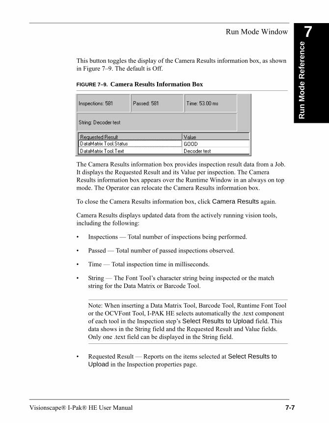
Run Mode Window
Ru
n M
od
e R
efer
ence
7
This button toggles the display of the Camera Results information box, as shown in Figure 7–9. The default is Off.
FIGURE 7–9. Camera Results Information Box
The Camera Results information box provides inspection result data from a Job. It displays the Requested Result and its Value per inspection. The Camera Results information box appears over the Runtime Window in an always on top mode. The Operator can relocate the Camera Results information box.
To close the Camera Results information box, click Camera Results again.
Camera Results displays updated data from the actively running vision tools, including the following:
• Inspections — Total number of inspections being performed.
• Passed — Total number of passed inspections observed.
• Time — Total inspection time in milliseconds.
• String — The Font Tool’s character string being inspected or the match string for the Data Matrix or Barcode Tool.
Note: When inserting a Data Matrix Tool, Barcode Tool, Runtime Font Tool or the OCVFont Tool, I-PAK HE selects automatically the .text component of each tool in the Inspection step’s Select Results to Upload field. This data shows in the String field and the Requested Result and Value fields. Only one .text field can be displayed in the String field.
• Requested Result — Reports on the items selected at Select Results to Upload in the Inspection properties page.
Visionscape® I-Pak® HE User Manual 7-7
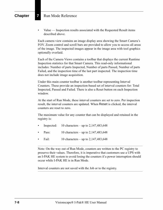
Chapter 7 Run Mode Reference
• Value — Inspection results associated with the Requested Result items described above.
Each camera view contains an image display area showing the Smart Camera’s FOV. Zoom control and scroll bars are provided to allow you to access all areas of the image. The inspected images appear in the image area with tool graphics optionally overlaid.
Each of the Camera Views contains a toolbar that displays the current Runtime Inspection statistics for that Smart Camera. This read-only informational includes: Number of parts Inspected, Number of parts Passed, Number of parts Failed, and the inspection time of the last part inspected. The inspection time does not include image acquisition.
Under this main counter toolbar is another toolbar representing Interval Counters. These provide an inspection-based set of interval counters for: Total Inspected, Passed and Failed. There is also a Reset button on each Inspection window.
At the start of Run Mode, these interval counters are set to zero. Per inspection result, the interval counters are updated. When Reset is clicked, the interval counters are reset to zero.
The maximum value for any counter that can be displayed and retained in the registry is:
• Inspected: 10 characters – up to 2,147,483,648
• Pass: 10 characters – up to 2,147,483,648
• Fail: 10 characters – up to 2,147,483,648
Note: On the way out of Run Mode, counters are written to the PC registry to preserve their values. Therefore, it is imperative that customers use a UPS with an I-PAK HE system to avoid losing the counters if a power interruption should occur while I-PAK HE is in Run Mode.
Interval counters are not saved with the Job or to the registry.
7-8 Visionscape® I-Pak® HE User Manual
Run Mode Window
Ru
n M
od
e R
efer
ence
7
Runtime Change LotChange Lot functionality allows a Programmer or Supervisor to quickly change the Data Matrix Tool match string, the Barcode Tool match string, the OCRTrainableFont Tool match string, and the OCVFont Tool layout string without retraining the tools in the Job.
When you click Change Lot, a prompt for a password is displayed. If a valid password is entered, the Change Lot dialog box is displayed. At this point, all inspections are stopped, and the I-PAK HE enters an off-line state. You should be sure that your production line is stopped when you are performing a Change Lot operation. Once complete, all inspections will be restarted, and I-PAK HE will be back On Line.
Password — 21 CFR Part 11 AccessIf 21 CFR Part 11 is active, you are prompted for user name and password.
You must enter a valid user name with the correct password to access the Change Lot dialog box. If System Settings > General > Enable User Logins for Training Approvals is enabled, the user name entered must have training authority. When Enable User Logins for Training Approvals is:
• Off — Operators can Change Lot in Run Mode
• On — Operators cannot Change Lot in Run Mode
Password — Standard AccessIf 21 CFR Part 11 is not active, you are prompted to enter either the current Supervisor password or the current Programmer password.
You must enter a valid password to access the Change Lot dialog box.
I-PAK HE provides a unique default password (1101) that allows an Operator who does not have Supervisor or Programmer access to use the Change Lot function. This allows the Operator to perform a Change Lot but does not allow the Operator to enter Setup Mode.
Change Lot Dialog BoxThe Run Mode Change Lot dialog box is the same as the Setup Mode Change Lot dialog box. If there are no Data Matrix Tools, Barcode Tools, OCVFont Tools, or OCRTrainableFont Tools in the product definition, the Change Lot dialog box is displayed “empty”, with none of the tool or string fields filled in
Visionscape® I-Pak® HE User Manual 7-9

Chapter 7 Run Mode Reference
(Figure 7–10). Otherwise, the dialog box displays the tools names and the associated match or layout strings (Figure 7–11).
FIGURE 7–10. Lot ChangeOver — Empty
• If Show Full Path is checked, I-PAK HE displays the full path to the tools, as shown in Figure 7–11:
FIGURE 7–11. Full Path to Tools Shown
7-10 Visionscape® I-Pak® HE User Manual
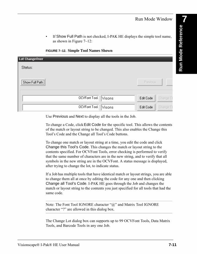
Run Mode Window
Ru
n M
od
e R
efer
ence
7
• If Show Full Path is not checked, I-PAK HE displays the simple tool name, as shown in Figure 7–12:
FIGURE 7–12. Simple Tool Names Shown
Use Previous and Next to display all the tools in the Job.
To change a Code, click Edit Code for the specific tool. This allows the contents of the match or layout string to be changed. This also enables the Change this Tool’s Code and the Change all Tool’s Code buttons.
To change one match or layout string at a time, you edit the code and click Change this Tool’s Code. This changes the match or layout string to the contents specified. For OCVFont Tools, error checking is performed to verify that the same number of characters are in the new string, and to verify that all symbols in the new string are in the OCVFont. A status message is displayed, after trying to change the lot, to indicate status.
If a Job has multiple tools that have identical match or layout strings, you are able to change them all at once by editing the code for any one and then clicking Change all Tool’s Code. I-PAK HE goes through the Job and changes the match or layout string to the contents you just specified for all tools that had the same code.
Note: The Font Tool IGNORE character “@” and Matrix Tool IGNORE character “?” are allowed in this dialog box.
The Change Lot dialog box can supports up to 99 OCVFont Tools, Data Matrix Tools, and Barcode Tools in any one Job.
Visionscape® I-Pak® HE User Manual 7-11

Chapter 7 Run Mode Reference
OverrunsI-PAK HE monitors Run Mode for process and trigger overruns. If one occurs, the I-PAK HE Overrun dialog box is displayed, as shown in Figure 7–13.
FIGURE 7–13. I-PAK HE Overrun! Dialog Box
Note: This should be considered an alarm condition and reported immediately to the Operator’s management. Efforts should be taken to prevent and correct overruns. When using Part 11, alarms must be acknowledged by providing your username and password.
When overruns occur, and their dialog box is displayed but not acknowledged by you, you will be alerted to these when you try to exit Run Mode and return to SetupMode. The password box will not be displayed until these overrun alarm messages have been acknowledged. Additionally, the timestamp of the overrun will be displayed in the message.
A process overrun occurs when images are not processed fast enough. The I-PAK HE system has a limited set of image buffers. When images are processed, image buffers are freed for re-use. If the buffers are not freed fast enough because image processing is taking too long, the acquisition process will run out of buffers.
A trigger overrun occurs when a trigger arrives, but the Smart Camera is still busy acquiring an image from the last trigger, and is therefore not capable of handling this trigger. See the HawkEye 1600T Smart Camera Guide to find out the maximum achievable rate for the image size selected in your application.
7-12 Visionscape® I-Pak® HE User Manual
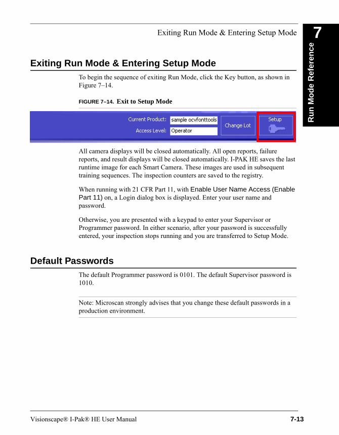
Exiting Run Mode & Entering Setup Mode
Ru
n M
od
e R
efer
ence
7
Exiting Run Mode & Entering Setup ModeTo begin the sequence of exiting Run Mode, click the Key button, as shown in Figure 7–14.
FIGURE 7–14. Exit to Setup Mode
All camera displays will be closed automatically. All open reports, failure reports, and result displays will be closed automatically. I-PAK HE saves the last runtime image for each Smart Camera. These images are used in subsequent training sequences. The inspection counters are saved to the registry.
When running with 21 CFR Part 11, with Enable User Name Access (Enable Part 11) on, a Login dialog box is displayed. Enter your user name and password.
Otherwise, you are presented with a keypad to enter your Supervisor or Programmer password. In either scenario, after your password is successfully entered, your inspection stops running and you are transferred to Setup Mode.
Default PasswordsThe default Programmer password is 0101. The default Supervisor password is 1010.
Note: Microscan strongly advises that you change these default passwords in a production environment.
Visionscape® I-Pak® HE User Manual 7-13
Chapter 7 Run Mode Reference
Forgotten PasswordsShould you forget your password, Microscan provides a mechanism to reset the password and get into the system ONCE. At the password keypad, enter 228489. A random string will appear on the password keypad.
Note: Make a note of the random string. Then, call Microscan’s customer service with the information displayed on the screen.
The Customer Service representative will be able to look up a one-time use password for you to enter.
If you are in Run Mode when you forget your password and contact Microscan, you can exit Run Mode into Setup Mode by using the password provided by Microscan Customer Service. Then, immediately go into the Change Password menu to reset your password.
If you are in Setup Mode when you forget your password, you must go into the Change Password menu after receiving the one-time password from Microscan’s Customer Service to reset it.
If you fail to reset your password and you go back to Run Mode, you will either have to remember your original password or call Microscan Customer Service again for a new one-time password.
Forgotten Passwords — 21 CFR Part 11Should you forget your 21 CFR Part 11 password, you’ll need to contact your I-PAK Administrator to suspend your existing user name and create a new user name and password. For more information about 21 CFR Part 11 and passwords, see Reset a User’s Password on page 3–17.
7-14 Visionscape® I-Pak® HE User Manual
End Batch
Ru
n M
od
e R
efer
ence
7
End BatchWhen running with the End Batch option On, I-PAK HE prompts you for a response to save the End Batch results:
• No — I-PAK HE just returns to Setup Mode and awaits further action from you.
• Yes — I-PAK HE begins to automatically save the read-only statistics file to the hard drive and prompts you for a file name as you return to Setup Mode.
• Cancelling out of this End Batch saving statistics file option is allowed.
Regardless of how you respond, you get an End Batch Successful message and the batch results are stored in the Statistics menus.
Visionscape® I-Pak® HE User Manual 7-15
Chapter 7 Run Mode Reference
7-16 Visionscape® I-Pak® HE User Manual
A
Inst
alla
tio
n &
S
oft
war
e
A
APPENDIX A Installation & Software
Before you install your Visionscape® I-PAK® HE, be sure you have all of the necessary I-PAK HE components and a supported PC.
Minimum PC Requirements
• Windows® 2000 SP4 PC or Windows® XP SP2 PC that meets the following minimum requirements:
– Microsoft Windows® 2000 SP4 or Microsoft Windows® XP SP2 or later
– Pentium 4, 2.4 GHz or higher orPentium 4, 1.66 GHz Core 2 Duo or higher
– 1 GB RAM memory
– VGA display adapter - 64K or true colors
– Screen Resolution:1024*768 or 1280*1024
– Dedicated Ethernet Network Port: 1 NIC card (100BaseT) + switch or 1 4-port NIC card, no switch. HE1600T Smart Camera subnet to be local to the PC using private addressing.orA standard network as long as the network uses static IP to minimize disconnection issues. Although the HawkEye supports DHCP, we
Visionscape® I-Pak® HE User Manual A-1
Appendix A Installation & Software
advise against using it in a production environment. When a DHCP server renews the lease on the IP address assigned to one of the HawkEyes, the connection to the I-PAK HE interface can be lost. If the connection is ever lost to a HawkEye 1600T, I-PAK HE will post an error message and shut down.
– RS-232 Port 1 which is used for user input of Match String Characters and output end of batch Runtime Statistics.
– CD R/W recommended.
– Screen Resolution Refresh: You should set the Refresh Frequency setting (Start > Settings > Control Panel > Display, etc.,) to a value that maximizes system performance. To accomplish this, increase the value of Refresh Frequency and use the Test button to make sure that the display is OK. Continue this process until the optimal Refresh Rate is determined.
Tested PCsThe following PCs have been completely tested with I-PAK HE Version 3.7.4:
• IPC 847B Rack, 1.66 GHz Intel Dual core T5500, 2GB
• IPC 627 Box, 2 GHz Pentium M, 1GB
• IPC 677 Panel, 2 GHz Pentium M, 1GB
Note: Neither the Box PC 840 nor the Rack PC 840 V2 are supported by Visionscape V3.7.4 or I-PAK HE V3.7.4.
I-PAK HE Components
• Visionscape V3.7.4 — On the software installation CD
• I-PAK HE — On the software installation CD
• Optional installs for the Visionscape VSKIT and Adobe Reader 8.12
• One to four HawkEye 1600T Smart Camera (one inspection and one snapshot per Smart Camera).
A-2 Visionscape® I-Pak® HE User Manual
Installing the Software
Inst
alla
tio
n &
S
oft
war
e
A
Note: On startup, a message is displayed that indicates that only resolutions 1024*768 and 1280*1024 are supported.Installing the SoftwareThis section describes how to install the I-PAK HE software, its driver, and its support software. The installation is allowed on the Windows 2000 and XP operating systems. Visionscape® Studio must be installed before you install I-PAK HE.
Before installing any software, ensure that you log into the computer with an account that has administrator privileges. Be sure to disable any virus protection software you are running.
The I-PAK HE CD contains the following folders:
• I-PAK_HE Setup — Contains the Visionscape® I-PAK® HE software.
• Visionscape_setup — Contains the Visionscape software.
• vskit — Contains the VSKit software and manual.
• Adobe Reader 8.12 Setup — Contains Adobe Reader V8.12 install software.
Installing the Visionscape® Software
1. To install the Visionscape® software, place the CD into the CD-ROM drive.
If this web browser is not displayed automatically, double click Setup.html (at the root of the CD).
2. Click Install Visionscape Software. The InstallShield Wizard starts, and displays the following screens:
– Several messages about Run or Save; click Run.
– Welcome screen; click Next.
– License Agreement screen; select the “I accept...” radio button, and then click Next.
Visionscape® I-Pak® HE User Manual A-3

Appendix A Installation & Software
– Select Destination screen; we suggest you accept the default location (C:\Vscape) and click Next.
– Start Copying Files screen; click Next.
– The installer displays the ReadMe.wri file, which you can read as the installer finishes.
The install process takes a couple of minutes. It may appear that nothing is happening, but that is not the case. Don’t try to do anything until you are prompted to reboot your PC.
All required components are automatically installed to your hard disk. The default location is:
C:\Vscape
Camera definition files are stored under:
\Vscape\Drivers\Camdefs
3. When the InstallShield Wizard prompts you to reboot your PC, select the Yes, I want to restart my computer now radio button, and then click Finish.
4. Wait for your PC to reboot.
5. Go to the next section to install the I-PAK HE software.
Installing the Visionscape® I-PAK HE Software
1. After your PC reboots, double click Setup.html (at the root of the CD).
2. Click Install Visionscape I-PAK HE Software. The InstallShield Wizard starts, and displays the following screens:
– Several messages about Run or Save; click Run.
– Welcome screen; click Next.
– License Agreement screen; select the “I accept...” radio button, and then click Next.
– Select Destination screen; we suggest you accept the default location (Visionscape I-PAK HE) and click Next.
A-4 Visionscape® I-Pak® HE User Manual
Software Upgrades — 21 CFR Part 11 Usage
Inst
alla
tio
n &
S
oft
war
e
A
– Start Copying Files screen; click Next.– The InstallShield Wizard Complete screen; click Finish.
3. Close the web browser
The I-PAK HE software is installed and ready for you to use.
Software Upgrades — 21 CFR Part 11 UsageThe Part 11 user names, their encrypted passwords, and the original time/datestamp when a user was created or last changed his or her password are stored in a data file called ipak.usr.
When you upgrade the I-PAK HE software, you must manually move the ipak.usr data file to the current version of I-PAK HE. These paths can be determined quickly by looking at the Compatibility section of the I-PAK HE ReadMe file or product information.
Uninstalling I-PAK HE Software
1. Open the Control Panel and run Add/Remove Programs.
2. Select I-PAK HE and click Add/Remove to remove the component.
3. Finally, restart the PC.
Starting the I-PAK HE ProgramWhen you successfully install the Visionscape® and I-PAK HE software, the installer automatically puts an Visionscape I-PAK HE shortcut into your Start > Visionscape > Visionscape I-PAK_HE sequence so that I-PAK HE automatically begins as soon as you have logged on.
Note: If you exit I-PAK HE, you can re-start by going to Start > Visionscape > Visionscape I-PAK_HE.
As part of the I-PAK HE start-up sequence, a splash screen is displayed and reports the start-up sequence, as shown in Figure A–1.
Visionscape® I-Pak® HE User Manual A-5
Appendix A Installation & Software
FIGURE A–1. I-PAK HE Splash Screen
After starting the interface, the Smart Camera is rebooted automatically. Once this is complete, the last run Job is downloaded and transfers control to Run Mode awaiting a trigger (if one is configured).
UPS & UPS SoftwareMicroscan mandates the use of an uninterruptable power supply (UPS), model Smart-UPS SC 420, with the I-PAK HE system. The UPS provides a safety factor so that your vision inspection system is protected from power outages and brown-outs.
The UPS ensures that I-PAK HE stays running by providing battery-backup for a user-specified time, then gracefully shutting down the I-PAK HE program, saving all batch data (Job name, counters, etc.,) and, finally, performing a PC shutdown before removing power to the PC.
Note: You may lose inspection counts if you do not use a UPS!
A-6 Visionscape® I-Pak® HE User Manual
UPS & UPS Software
Inst
alla
tio
n &
S
oft
war
e
A
When power is restored, the PC restarts and the I-PAK HE program starts up, downloading the last run Job, restoring all previous counters and awaiting a trigger (if configured) to continue inspection.We supply one of two Uninterruptable Power Supplies depending on the voltage required at the customer site. Depending on availability, actual model numbers may change while functionality remains intact.
• 120 Volt version: APC BP420SUS;Part Number: RVA:93300781
• 240 Volt Version: APC SC420i; Part Number: RVA:93300811
Both of these UPS are external. They are not inside the I-PAK HE enclosure due to their form factor.
Note: After installing the UPS, the installer should add the appropriate labels, in the appropriate language, to the side of the UPS.
Configuring the UPS SoftwareI-PAK HE uses the Windows integrated UPS support. Therefore, it’s necessary to set up some parameters (e.g., the UPS type) using the Windows Control Panel.
1. Select Start > Settings > Control Panel to open the Windows Control Panel.
2. Double click Power Options.
3. Click on the UPS tab.
The Uninterruptible Power Supply dialog box is displayed, as shown in Figure A–2.
Visionscape® I-Pak® HE User Manual A-7
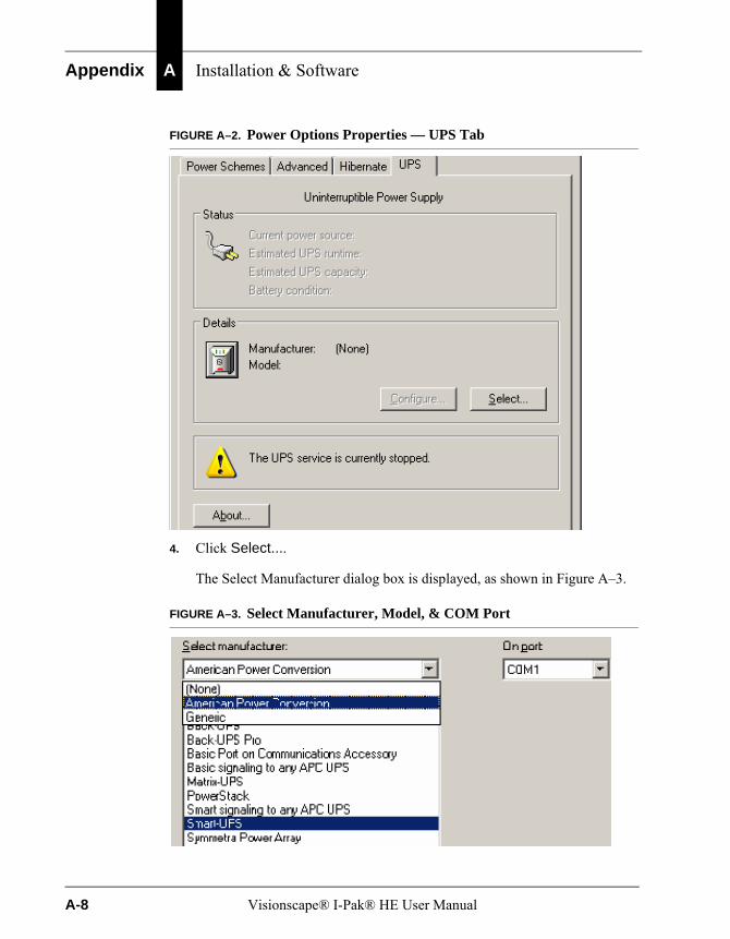
Appendix A Installation & Software
FIGURE A–2. Power Options Properties — UPS Tab
4. Click Select....
The Select Manufacturer dialog box is displayed, as shown in Figure A–3.
FIGURE A–3. Select Manufacturer, Model, & COM Port
A-8 Visionscape® I-Pak® HE User Manual

UPS & UPS Software
Inst
alla
tio
n &
S
oft
war
e
A
5. In the Select manufacturer drop down menu, select American PowerConversion.
6. In the Select model list, highlight (to select) Smart-UPS.
7. In the On port drop down menu, select the COM Port you have chosen to connect the UPS system to your PC.
8. Click Finish to store the selected values.
The following dialog box is displayed.
FIGURE A–4. Power Options Properties — UPS Tab with Configure Enabled
9. Click Configure.
The following dialog box is displayed.
Visionscape® I-Pak® HE User Manual A-9
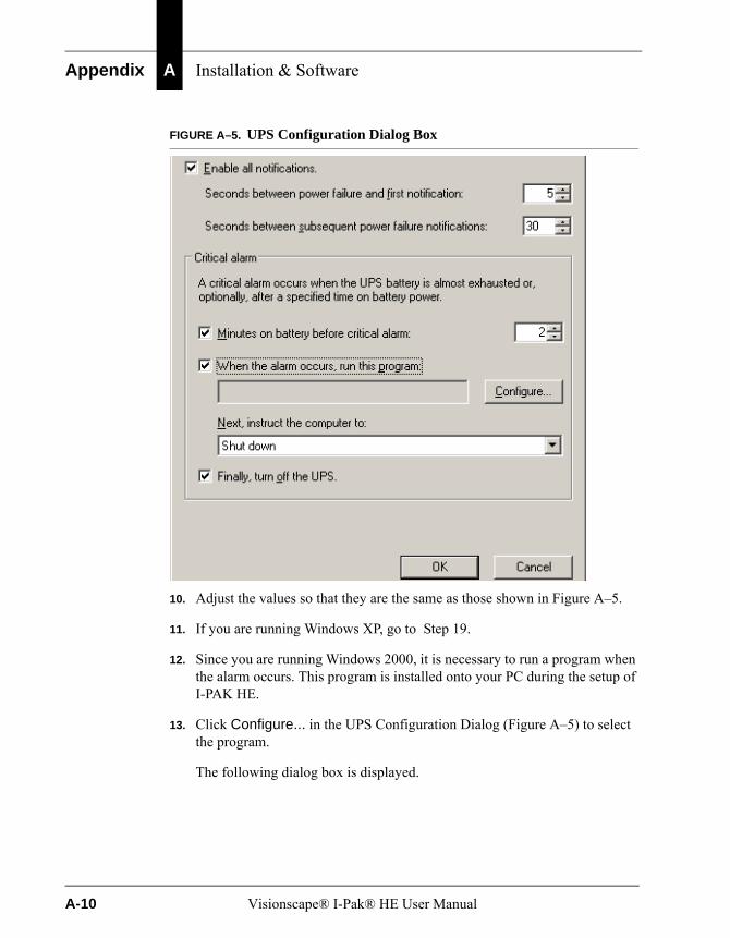
Appendix A Installation & Software
FIGURE A–5. UPS Configuration Dialog Box
10. Adjust the values so that they are the same as those shown in Figure A–5.
11. If you are running Windows XP, go to Step 19.
12. Since you are running Windows 2000, it is necessary to run a program when the alarm occurs. This program is installed onto your PC during the setup of I-PAK HE.
13. Click Configure... in the UPS Configuration Dialog (Figure A–5) to select the program.
The following dialog box is displayed.
A-10 Visionscape® I-Pak® HE User Manual
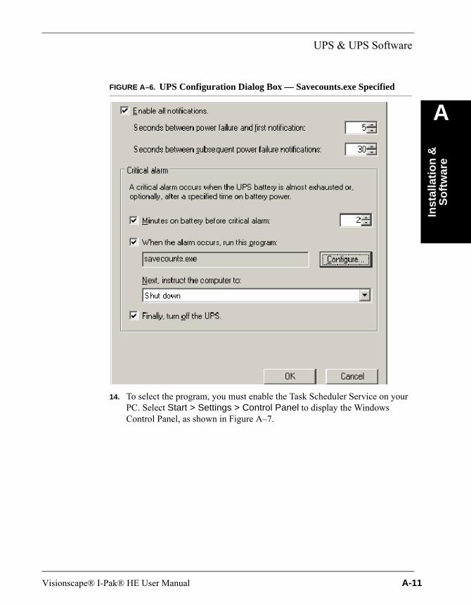
UPS & UPS Software
Inst
alla
tio
n &
S
oft
war
e
A
FIGURE A–6. UPS Configuration Dialog Box — Savecounts.exe Specified14. To select the program, you must enable the Task Scheduler Service on your PC. Select Start > Settings > Control Panel to display the Windows Control Panel, as shown in Figure A–7.
Visionscape® I-Pak® HE User Manual A-11
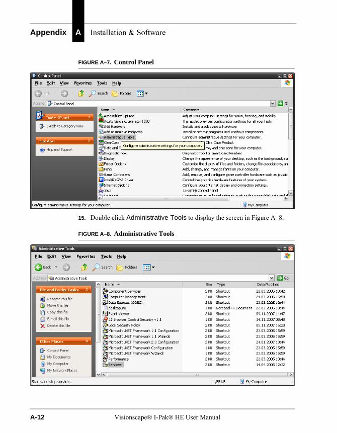
Appendix A Installation & Software
FIGURE A–7. Control Panel
15. Double click Administrative Tools to display the screen in Figure A–8.
FIGURE A–8. Administrative Tools
A-12 Visionscape® I-Pak® HE User Manual

UPS & UPS Software
Inst
alla
tio
n &
S
oft
war
e
A
16. Double click Services to display the list in Figure A–9.FIGURE A–9. Services
17. Double click Task Scheduler to display the Task Scheduler Properties page, as shown in Figure A–10.
Visionscape® I-Pak® HE User Manual A-13

Appendix A Installation & Software
FIGURE A–10. Task Scheduler Properties Page
18. In the Startup type pull-down menu, specify Automatic. Click Apply and then click OK.
After Apply has finished, the Start button will become active and you can start the service by clicking Start.
19. Close the Power Option Properties dialog box.
A-14 Visionscape® I-Pak® HE User Manual
CD-RW Support
Inst
alla
tio
n &
S
oft
war
e
A
CD-RW SupportI-PAK HE supports a CD-RW for the archival and restoration of its product definition files.
To add a CD-RW, install the CD-RW in place of the CD in the I-PAK HE PC. Installing the CD-RW hardware is not included in this description.
Windows XPFor Windows XP, you can use the integrated “CD burning” functionality. It is no longer necessary to install special CD writer software.
Note: If you use the integrated burn functionality, it is only possible to copy files to a subfolder of the CD drive, and not to the root of the CD drive.
Windows 2000For Windows 2000, you must install “CD burning” software. Normally, this is delivered with the CD-Writer hardware.
Visionscape® I-Pak® HE User Manual A-15

Appendix A Installation & Software
A-16 Visionscape® I-Pak® HE User Manual
B
Co
nn
ecti
ng
Sm
art
Cam
eras
to
a P
C
B
APPENDIX B Connecting Smart Cameras to a PCConnecting Smart Cameras to a PC using Static IP Addresses & a Network Switch
To prevent issues with unexpected network disconnections, we recommend that you connect your HawkEye 1600T Smart Cameras directly to your PC using either a multi-port NIC card or an Ethernet Switch, and static IP addresses. In this appendix, we describe how to connect up to four HawkEye Smart Cameras to your PC using an Ethernet switch and static IP addressing.
Connecting a PC & Smart Cameras to an Ethernet SwitchFigure B–1 shows how to connect your PC and up to four HawkEye 1600T Smart Cameras to a typical 5-port Ethernet Switch (also referred to as a Hub).
Visionscape® I-Pak® HE User Manual B-1
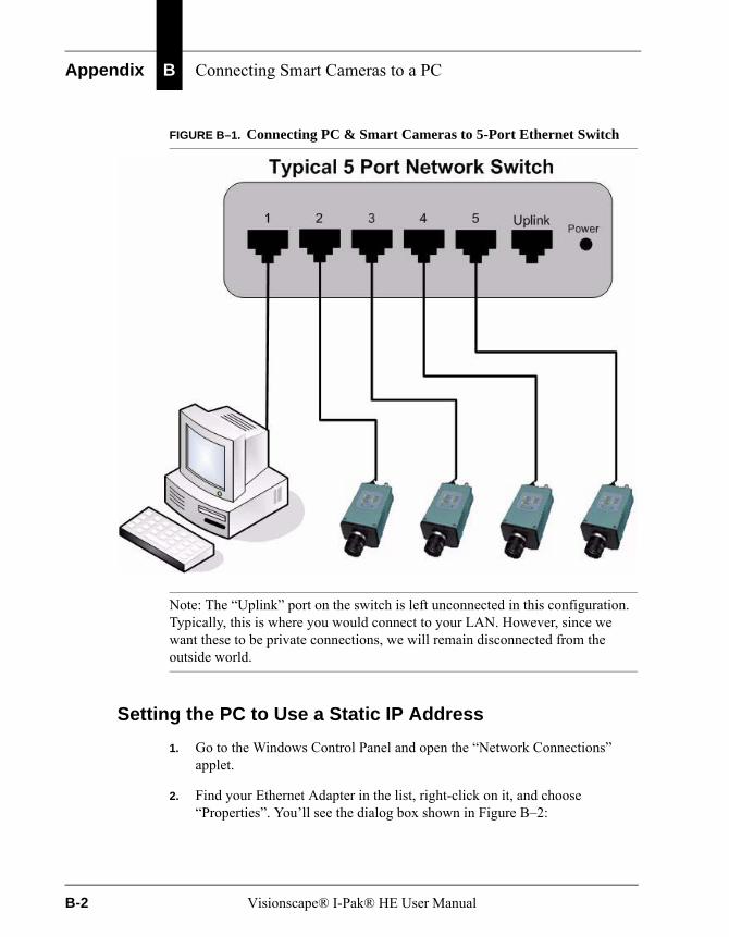
Appendix B Connecting Smart Cameras to a PC
FIGURE B–1. Connecting PC & Smart Cameras to 5-Port Ethernet Switch
Note: The “Uplink” port on the switch is left unconnected in this configuration. Typically, this is where you would connect to your LAN. However, since we want these to be private connections, we will remain disconnected from the outside world.
Setting the PC to Use a Static IP Address
1. Go to the Windows Control Panel and open the “Network Connections” applet.
2. Find your Ethernet Adapter in the list, right-click on it, and choose “Properties”. You’ll see the dialog box shown in Figure B–2:
B-2 Visionscape® I-Pak® HE User Manual

Connecting Smart Cameras to a PC using Static IP Addresses &
Co
nn
ecti
ng
Sm
art
Cam
eras
to
a P
C
B
FIGURE B–2. Local Area Connection Properties Dialog Box
3. Highlight (to select) “Internet Protocol (TCP/IP)” and then click Properties.
4. On the “General” tab, click the “Use the following IP address” radio button, and then enter the settings shown in Figure B–3:
Visionscape® I-Pak® HE User Manual B-3

Appendix B Connecting Smart Cameras to a PC
FIGURE B–3. Internet Protocol (TCP/IP) Properties Dialog Box
Note: Although we’ve chosen an IP address of 192.168.254.2, this is not the only IP address that will work. The important point to remember is that the network portion of your chosen IP address must match the network portion of the addresses you assign to your HawkEye 1600T Smart Cameras. The network portion of the IP address is defined by the subnet mask so, to use our example above, 192.168.254 represents the network number, and the value 2 represents the host number. It is this last number, the host number, that must be unique for each of the devices we connect to our switch.
5. Click OK, then click OK again.
Your PC is now using the Static IP address of 192.168.254.2.
Setting the Smart Cameras to Use Static IP AddressesBy default, Smart Cameras are configured to use DHCP. Since we will not be connected to a DHCP server in this configuration, we need to disable DHCP on the Smart Camera, and assign the static IP address that we wish to use.
1. Connect the serial cable that is included with your Smart Camera to your PC’s COM Port, and to the Smart Camera’s Serial Port.
B-4 Visionscape® I-Pak® HE User Manual

Connecting Smart Cameras to a PC using Static IP Addresses &
Co
nn
ecti
ng
Sm
art
Cam
eras
to
a P
C
B
2. From Windows, start HyperTerminal:
Start > All Programs > Accessories > Communications > HyperTerminal
3. You’ll be asked to assign a name to your connection. Enter the following:
FIGURE B–4. Connection Description Dialog Box
4. Click OK. When the Connect To dialog box is displayed, select the PC Serial Port you wish to use (for this example, we will use COM1; switch to COM2 if COM1 is not available), and then click OK.
Visionscape® I-Pak® HE User Manual B-5

Appendix B Connecting Smart Cameras to a PC
FIGURE B–5. Connect To Dialog Box
5. In the “Port Settings” tab of the COM Port Properties dialog box, select the values shown in Figure B–6:
B-6 Visionscape® I-Pak® HE User Manual
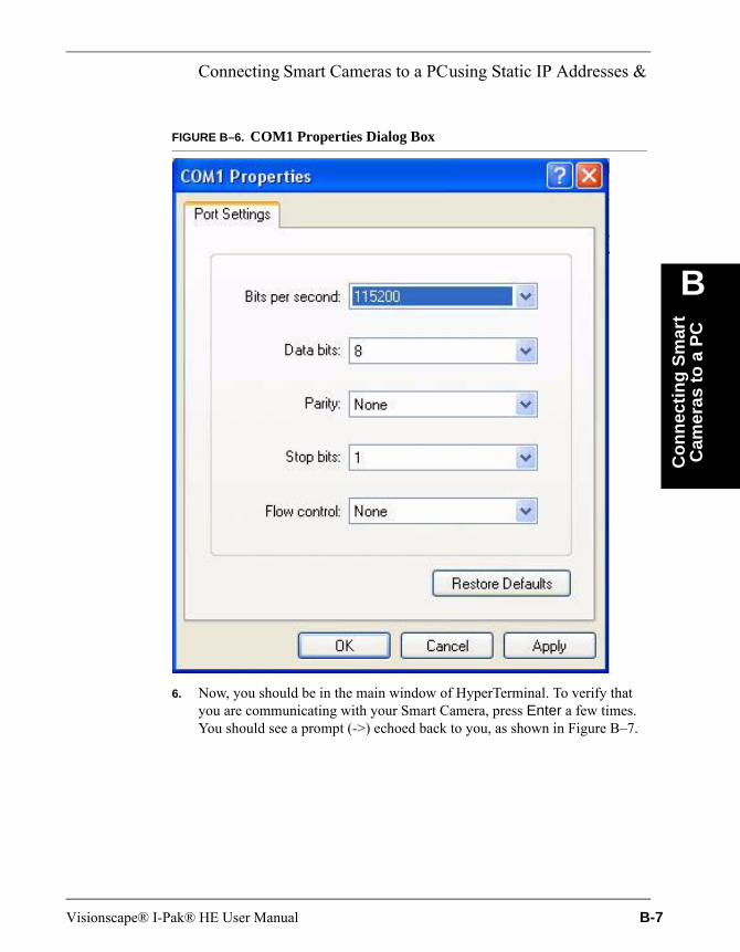
Connecting Smart Cameras to a PC using Static IP Addresses &
Co
nn
ecti
ng
Sm
art
Cam
eras
to
a P
C
B
FIGURE B–6. COM1 Properties Dialog Box
6. Now, you should be in the main window of HyperTerminal. To verify that you are communicating with your Smart Camera, press Enter a few times. You should see a prompt (->) echoed back to you, as shown in Figure B–7.
Visionscape® I-Pak® HE User Manual B-7
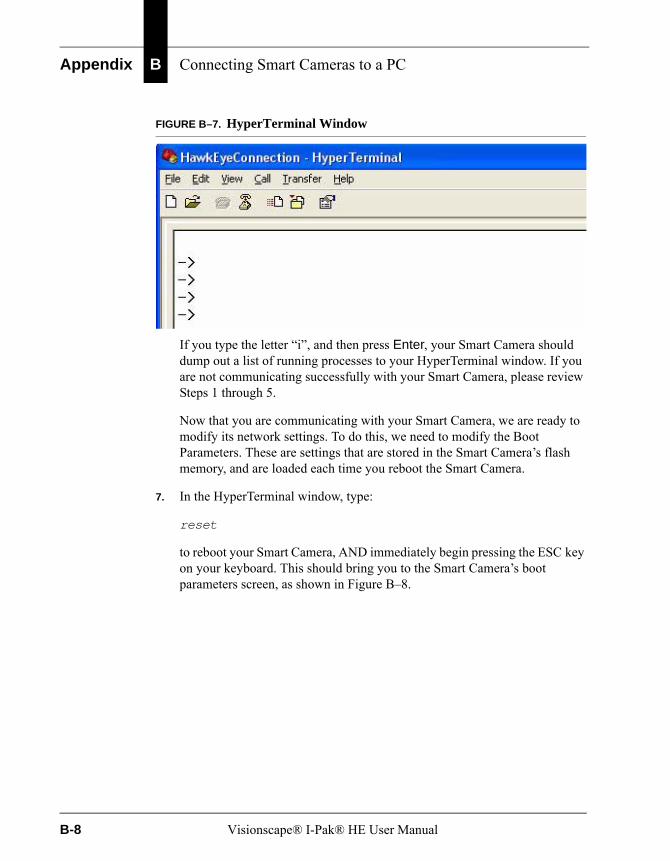
Appendix B Connecting Smart Cameras to a PC
FIGURE B–7. HyperTerminal Window
If you type the letter “i”, and then press Enter, your Smart Camera should dump out a list of running processes to your HyperTerminal window. If you are not communicating successfully with your Smart Camera, please review Steps 1 through 5.
Now that you are communicating with your Smart Camera, we are ready to modify its network settings. To do this, we need to modify the Boot Parameters. These are settings that are stored in the Smart Camera’s flash memory, and are loaded each time you reboot the Smart Camera.
7. In the HyperTerminal window, type:
reset
to reboot your Smart Camera, AND immediately begin pressing the ESC key on your keyboard. This should bring you to the Smart Camera’s boot parameters screen, as shown in Figure B–8.
B-8 Visionscape® I-Pak® HE User Manual
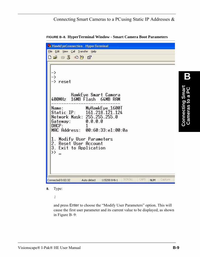
Connecting Smart Cameras to a PC using Static IP Addresses &
Co
nn
ecti
ng
Sm
art
Cam
eras
to
a P
C
B
FIGURE B–8. HyperTerminal Window - Smart Camera Boot Parameters
8. Type:
1
and press Enter to choose the “Modify User Parameters” option. This will cause the first user parameter and its current value to be displayed, as shown in Figure B–9:
Visionscape® I-Pak® HE User Manual B-9
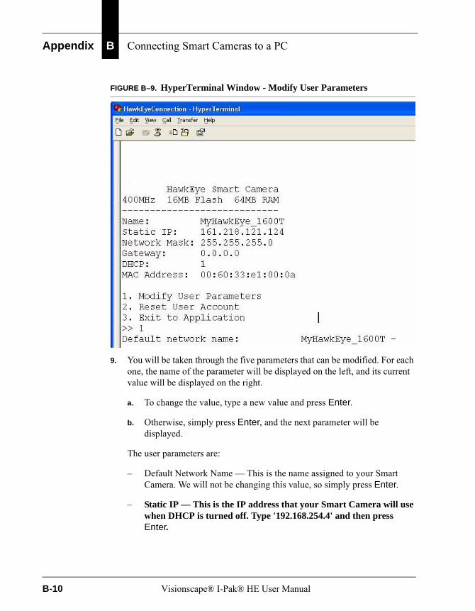
Appendix B Connecting Smart Cameras to a PC
FIGURE B–9. HyperTerminal Window - Modify User Parameters
9. You will be taken through the five parameters that can be modified. For each one, the name of the parameter will be displayed on the left, and its current value will be displayed on the right.
a. To change the value, type a new value and press Enter.
b. Otherwise, simply press Enter, and the next parameter will be displayed.
The user parameters are:
– Default Network Name — This is the name assigned to your Smart Camera. We will not be changing this value, so simply press Enter.
– Static IP — This is the IP address that your Smart Camera will use when DHCP is turned off. Type '192.168.254.4' and then press Enter.
B-10 Visionscape® I-Pak® HE User Manual
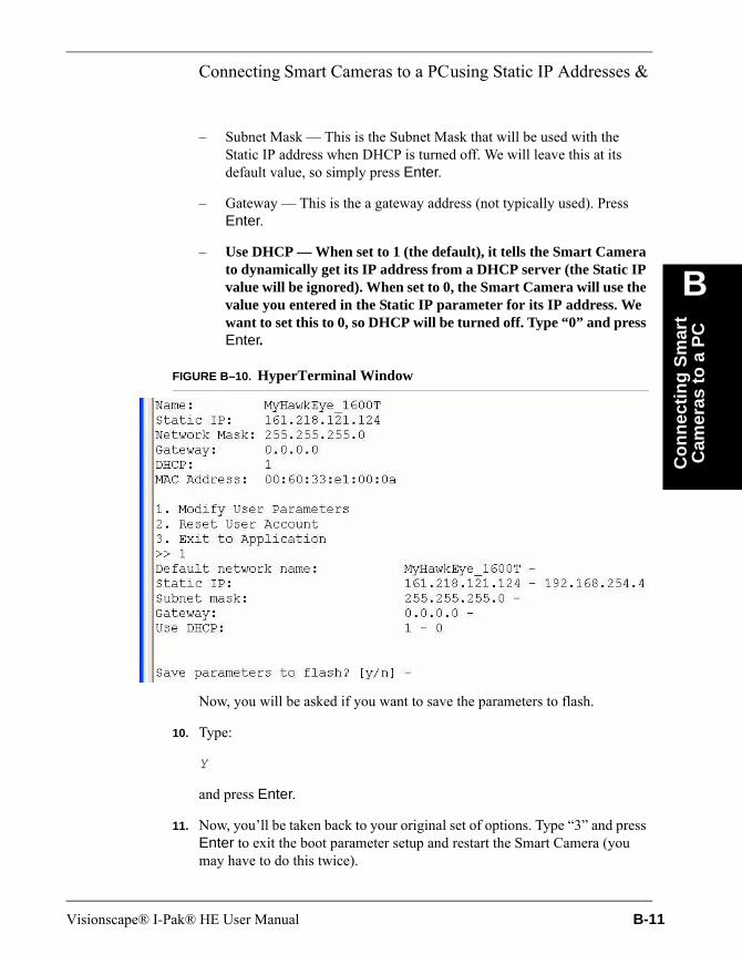
Connecting Smart Cameras to a PC using Static IP Addresses &
Co
nn
ecti
ng
Sm
art
Cam
eras
to
a P
C
B
– Subnet Mask — This is the Subnet Mask that will be used with the Static IP address when DHCP is turned off. We will leave this at its default value, so simply press Enter.
– Gateway — This is the a gateway address (not typically used). Press Enter.
– Use DHCP — When set to 1 (the default), it tells the Smart Camera to dynamically get its IP address from a DHCP server (the Static IP value will be ignored). When set to 0, the Smart Camera will use the value you entered in the Static IP parameter for its IP address. We want to set this to 0, so DHCP will be turned off. Type “0” and press Enter.
FIGURE B–10. HyperTerminal Window
Now, you will be asked if you want to save the parameters to flash.
10. Type:
Y
and press Enter.
11. Now, you’ll be taken back to your original set of options. Type “3” and press Enter to exit the boot parameter setup and restart the Smart Camera (you may have to do this twice).
Visionscape® I-Pak® HE User Manual B-11
Appendix B Connecting Smart Cameras to a PC
Note: If you will be using 2, 3 or 4 HawkEye 1600T Smart Cameras, then repeat Steps 7 through 10 for each of your additional Smart Cameras. Use the following static IP addresses in Step 9 for the Smart Cameras:
2nd HawkEye Smart Camera: 192.168.254.63rd HawkEye Smart Camera: 192.168.254.84th HawkEye Smart Camera: 192.168.254.10
You are done.
Verifying the Setup Using the Network BrowserThe Network Browser displays all of the Smart Cameras that can be detected on your Ethernet port. Now that you have switched your PC and all of your Smart Cameras to a static IP address, verify that they can talk to each other by launching this utility:
1. Go to Start > All Programs > Visionscape > Tools > Visionscape Network Browser.
2. When the Network Browser window is displayed (Figure B–11), you should see your Smart Camera(s) listed if Visionscape can detect them over your Ethernet connection.
– You can communicate with Smart Cameras listed with black text.
– You cannot communicate with Smart Cameras listed with red text. Generally, this means that they are configured to use a different network number than that of your PC.
B-12 Visionscape® I-Pak® HE User Manual
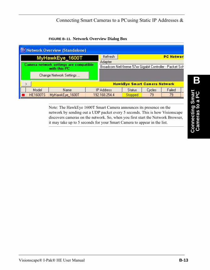
Connecting Smart Cameras to a PC using Static IP Addresses &
Co
nn
ecti
ng
Sm
art
Cam
eras
to
a P
C
B
FIGURE B–11. Network Overview Dialog Box
Note: The HawkEye 1600T Smart Camera announces its presence on the network by sending out a UDP packet every 5 seconds. This is how Visionscape discovers cameras on the network. So, when you first start the Network Browser, it may take up to 5 seconds for your Smart Camera to appear in the list.
Visionscape® I-Pak® HE User Manual B-13

Appendix B Connecting Smart Cameras to a PC
B-14 Visionscape® I-Pak® HE User Manual
C
Dem
o M
od
e
C
APPENDIX C Demo Mode
Demo Mode allows you to display quickly the capabilities of Visionscape® I-PAK® HE. Demo Mode is password protected. It allows I-PAK HE to run a saved Job, using saved images, for a pre-set amount of time and then switch to the next desired Job and run it. Demo Mode runs automatically until you manually enter Setup Mode.
Note: You need a Visionscape® dongle to run in Demo Mode with a Software System (for more information, see “Software Systems” on page 1-9).
Note: You cannot use 21 CFR Part 11 with Demo Mode.
Copying Job, Font, & Image FilesBefore you can use Demo Mode, you need to copy Job, Font, and image files to other locations:
1. Copy the Job (*.avp, *.avpsys) files:
From: C:\Vscape\I-PAK_HE\DemoTo: C:\Vscape\I-PAK_HE\Jobs
2. After copying these files, select all of the AVP and AVPSYS files in this directory. Right click on any file and select Properties. Turn Off (Uncheck) the Read Only attribute. Click the OK button.
Visionscape® I-Pak® HE User Manual C-1
Appendix C Demo Mode
3. Copy the font (*.ocv) files:
From: C:\Vscape\I-PAK_HE\DemoTo: C:\Vscape\Jobs\Fonts
4. After copying these files, select all of the OCV files in this directory. Right click on any file and select Properties. Turn Off (Uncheck) the Read Only attribute. Click the OK button.
5. Create the C:\demo_img folder.
6. Copy the image (*.tif) files:
From: C:\Vscape\I-PAK_HE\DemoTo: C:\demo_img
Check Jobs Before Running Demo Mode
1. Before using Demo Mode, use Change Product to load the Job.
2. A Device Error dialog box may be displayed. Click the Select a Different Device button and choose the Smart Camera that should run this Job. If the Save Product dialog box appears, click the Yes button.
3. You need to disable Enable Failed Image Queue, and set the image upload rate, before you use Demo Mode:
a. Go to Setup Mode.
b. Click Advanced Settings > System Settings > Training and Results.
c. Uncheck Enable Failed Image Queue.
d. For Image Upload Max Rate Per Second, click (to select) Maximum.
e. Click OK, and then click Close Advanced.
4. Run the product and verify that the counters increment and that the images update.
5. Repeat this procedure for each product that will be run in Demo Mode.
C-2 Visionscape® I-Pak® HE User Manual

Demo Mode Jobs
Dem
o M
od
e
C
Demo Mode JobsBefore entering Demo Mode, you can create several products that show the functionality that you want to demonstrate. These products should be configured so that they Load Images from File instead of Acquire from Camera. You can modify this when you train the selected product.
When the current step is the Snapshot, click Tool Settings and then click the Acquire tab. The Tool Settings dialog box is displayed, as shown in Figure C–1. which shows how one of the demo Jobs has been configured.
FIGURE C–1. Load Images From File
Enabling Demo ModeTo access Demo Mode, exit Run Mode using the password 78743366. After this password is entered, you enter Setup Mode with the Programmer access level.
To enable Demo Mode:
1. From Setup Mode, click Advanced Settings. You will see the Demo Mode button displayed on the left.
2. Click Demo Mode. The Demo Mode Products dialog box is displayed, as shown in Figure C–2.
Visionscape® I-Pak® HE User Manual C-3
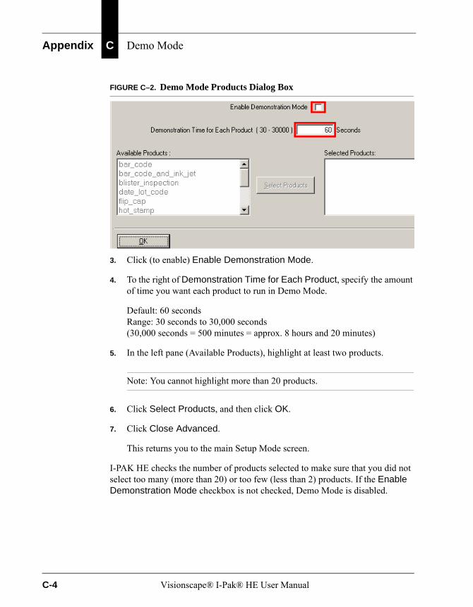
Appendix C Demo Mode
FIGURE C–2. Demo Mode Products Dialog Box
3. Click (to enable) Enable Demonstration Mode.
4. To the right of Demonstration Time for Each Product, specify the amount of time you want each product to run in Demo Mode.
Default: 60 secondsRange: 30 seconds to 30,000 seconds(30,000 seconds = 500 minutes = approx. 8 hours and 20 minutes)
5. In the left pane (Available Products), highlight at least two products.
Note: You cannot highlight more than 20 products.
6. Click Select Products, and then click OK.
7. Click Close Advanced.
This returns you to the main Setup Mode screen.
I-PAK HE checks the number of products selected to make sure that you did not select too many (more than 20) or too few (less than 2) products. If the Enable Demonstration Mode checkbox is not checked, Demo Mode is disabled.
C-4 Visionscape® I-Pak® HE User Manual
Running in Demo Mode
Dem
o M
od
e
C
Running in Demo ModeIf Demo Mode is enabled when you return to the main Setup Mode screen, the I-PAK HE title bar will display:
Visionscape I-PAK HE V3.7.4 Setup Mode - Demonstration Mode
After you click Run Mode, I-PAK HE enters Demo Mode. I-PAK HE loads the first product in the selected product list and runs it for the time set in the Demonstration Mode Parameters dialog box.
Note: For a new product not associated with a device, you will be prompted to specify a device. This is only for the first time. Once the product is associated with a given device, you do not have to choose a device again.
Once the time limit for a product has been reached, I-PAK HE automatically stops the product, enters Setup Mode, changes to the next product in the list, and returns to Run Mode. This cycle continues indefinitely until you manually exit Run Mode.
Disabling Demo ModeEach of these methods will disable Demo Mode:
• The first method is to change to a different user mode (User, Supervisor, or Programmer). If any password other than 78743366 is entered, Demo Mode is disabled and the button removed from the Advanced Settings menu.
• The second method can be used if you are in Demo Mode and I-PAK HE is currently in Setup Mode. In this scenario, you can enter the Advanced Settings menu, click Demo Mode (which displays the Demo Mode Parameters dialog box), and uncheck the Enable Demonstration Mode checkbox. This prevents Demo Mode from being activated when Run Mode is clicked. This option will not remove the Demo Mode button from the Advanced Settings menu. The Demo Mode button is only removed when you change to a different user mode.
• The third method is to close and restart I-PAK HE.
Visionscape® I-Pak® HE User Manual C-5

Appendix C Demo Mode
C-6 Visionscape® I-Pak® HE User Manual
D
Per
l Gem
s: T
ips
&
Tech
niq
ues
D
APPENDIX D Perl Gems: Tips & Techniques
Custom Steps and CustomVision Tools allow new steps and tools to be used in Visionscape® using Perl, an interpreted script language. These steps are now available in Visionscape® I-PAK® HE, with a limited set of I-PAK HE supported Perl language Package Scripts. Only the steps illustrated are supported.
Note: I-PAK HE supports the Package Scripts as they are distributed with the I-PAK HE software. Changing these script files or creating new script files renders them unsupported and non-validated by I-PAK HE.
I-PAK HE Custom Step & CustomVision ToolI-PAK HE software allows a Custom Step or CustomVision Tool to be inserted anywhere in a Product Definition. The CustomVision Tool has a built in Input Datum for accessing a buffer (Input Buffer) on which to perform a vision operation. The Custom Step does not support an Input Buffer and can only be used for non-vision operations.
Properties PagesEach Perl Package Script has a unique Properties Page. You can change the values of the input datums required by the script. Every script results in a minimum set of common properties. These properties are the only properties of the “none” script.
Visionscape® I-Pak® HE User Manual D-1

Appendix D Perl Gems: Tips & Techniques
Custom StepThe Custom Step consists of optional input datums, optional output datums and a script file written in the Perl programming language. The Perl Package Script determines the number and type of inputs and outputs. The Perl Package Script controls the functionality of the Custom Step. Custom Steps cannot perform vision operations because they do not allow for a buffer to be input to the Perl Package Script.
The Custom Step supports the following scripts:
• “none” on page D-2
• “FailCode” on page D-3
noneThe “none” script is the default Perl Package Script used by a Custom Step when inserted into a Job. This script has no functionality.
FIGURE D–1. The “none” Script
• Avail Package Scripts — This property allows selection of a Perl Package Script for the step to use. You can select:
– none
– “FailCode” on page D-3
• Re-Parse Package Script — When clicked, this button causes the package script to be parsed. Whenever any changes to the script files are made, this button needs to be clicked to make these changes take effect.
Note: I-PAK HE supports the Package Scripts as they are distributed with the I-PAK HE software. Changing these script files or creating new script files renders them unsupported and non-validated by I-PAK HE.
D-2 Visionscape® I-Pak® HE User Manual
I-PAK HE Custom Step & CustomVision Tool
Per
l Gem
s: T
ips
&
Tech
niq
ues
D
• Recreate Step Datums — When clicked, this button causes the input and output datum lists in the step to be re-created. You only need to click this button when a datum is added, removed or changed in the script. If the script is changed, but no input or output datums are changed, then this button does not need to be clicked. Clicking this button also causes all input datums to be set to their default values and to lose their connections to other step results or parameters.
Datums created by the package script are added to the user interface. Input datums are shown as a box with a drop-down list button. The input datums can be linked to other similar type datums in the Job. Clicking the drop-down list button causes the Job tree to be displayed, allowing you to select the datum to link to the input datum. Resource datums are shown as user-editable boxes that can be set to a value directly. Output datums are not shown in the user interface for this step, but can be seen in the Job tree that comes up when linking an input datum.
Note: I-PAK HE supports the Package Scripts as they are distributed with the I-PAK HE software. Changing these script files or creating new script files renders them unsupported and non-validated by I-PAK HE.
FailCodeThe FailCode script allows you to encode the failed statuses of various Steps in your Job into a single 32 bit integer value. Typically, this is used when you want to cut down on the amount of data that is uploaded from the inspection, but also want to know the status of a large number of Steps.
When added to your Job, the FailCode script will present you with a list of 32 inputs on the properties page, as shown in Figure D–2:
Visionscape® I-Pak® HE User Manual D-3
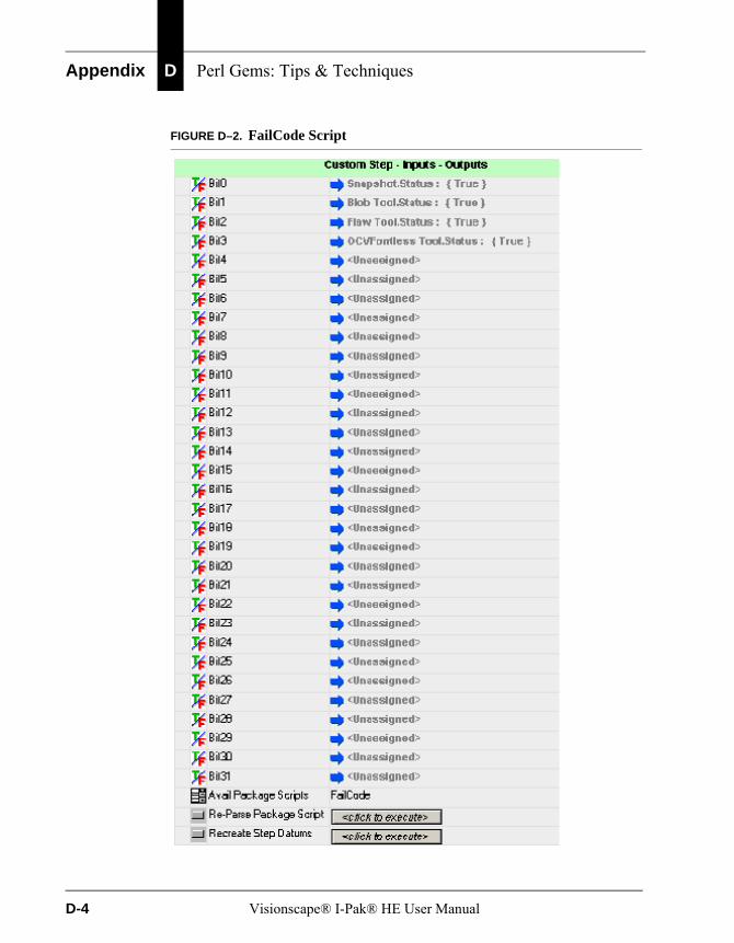
Appendix D Perl Gems: Tips & Techniques
FIGURE D–2. FailCode Script
D-4 Visionscape® I-Pak® HE User Manual
I-PAK HE Custom Step & CustomVision Tool
Per
l Gem
s: T
ips
&
Tech
niq
ues
D
Each of these inputs can be connected to any Status datum in your Job. Typically, you would connect the Statuses of all of the Steps whose pass/fail state you care about. In the example here, we have connected the statuses of the Snapshot step to Bit 0, a Blob Step to Bit 1, a Flaw Tool to Bit 2 and an OCVFontless Tool to Bit 3. If all of these Steps should pass, the FailCode script will produce an output value of 0. If any of these Steps should fail, the corresponding Bit in the output integer value will be set to a 1. So, for example, if the Blob tool and the OCVFontless tool should fail, this would mean that bits 1 and 3 would be set to 1, producing an output value of 10. Any Bits that are left “Unassigned” are ignored and will not effect the output value.
Settings
• Bit0 - Bit31 — Each of these input datums can be connected to any Status Datum in the Job. If the Status is False, then the corresponding bit of the output word is set to 1.
Results
• Output Value — This integer value holds the failure code. The bits of this word correspond to the 32 input datum values.
Custom Vision ToolThe CustomVision Tool consists of an input image (required), optional input datums, optional output datums and a script file written in the Perl programming language. The Perl Package Script determines the number and type of inputs and outputs. The Perl Package Script controls the functionality of the CustomVision Tool. CustomVision Tools can perform vision operations because they require a buffer to be input to the Perl Package Script.
The Custom Vision Tool supports the following scripts:
• “none” on page D-6
• “Cylinder_UnWarp” on page D-7
• “Dynamic_Binarize” on page D-10
• “FailCode” on page D-14
• “FindRotated” on page D-14
Visionscape® I-Pak® HE User Manual D-5

Appendix D Perl Gems: Tips & Techniques
noneThe “none” script is the default Perl Package Script used by a CustomVision Tool when inserted into a Job. This script has no functionality.
FIGURE D–3. The “none” Script
• Avail Package Scripts — This property allows selection of a Perl Package Script for the step to use. You can select:
– none
– “Cylinder_UnWarp” on page D-7
– “Dynamic_Binarize” on page D-10
– “FailCode” on page D-14
– “FindRotated” on page D-14
• Re-Parse Package Script — When clicked, this button causes the package script to be parsed. Whenever any changes to the script files are made, this button needs to be clicked to make these changes take effect.
Note: I-PAK HE supports the Package Scripts as they are distributed with the I-PAK HE software. Changing these script files or creating new script files renders them unsupported and non-validated by I-PAK HE.
• Recreate Step Datums — When clicked, this button causes the input and output datum lists in the step to be re-created. You only need to click this button when a datum is added, removed or changed in the script. If the script is changed, but no input or output datums are changed, then this button does not need to be clicked. Clicking this button also causes all input datums to be set to their default values and to lose their connections to other step results or parameters.
D-6 Visionscape® I-Pak® HE User Manual
I-PAK HE Custom Step & CustomVision Tool
Per
l Gem
s: T
ips
&
Tech
niq
ues
D
Datums created by the package script are added to the user interface. Input datums are shown as a box with a drop-down list button. The input datums can be linked to other similar type datums in the Job. Clicking the drop-down list button causes the Job tree to be displayed, allowing you to select the datum to link to the input datum. Resource datums are shown as user-editable boxes that can be set to a value directly. Output datums are not shown in the user interface for this step, but can be seen in the Job tree that comes up when linking an input datum.
Note: I-PAK HE supports the Package Scripts as they are distributed with the I-PAK HE software. Changing these script files or creating new script files renders them unsupported and non-validated by I-PAK HE.
Cylinder_UnWarpThis step is an image-in, image-out operation, and unwraps an image on a cylindrical surface, reducing the distortion caused by the surface.
Theory of OperationGiven a description of the geometry of a cylinder, the CylinderUnwrap step will warp the image on the cylinder in such a way as to unwrap the image onto a flat surface. This reduces the distortion caused by the cylindrical surface.
The geometry of the cylinder is specified using the:
• Radius of the cylinder
• Distance the cylinder is from the camera
• Vertical axis of the cylinder
• Point within the ROI where the image is correct (not distorted)
Cylinder Unwrap ROIThe Cylinder Unwrap ROI is a rotatable rectangle. Typically, the rectangle is rotated to match the angle of the cylinder axis.
Using the Cylinder Unwrap WarpTypically, other tools and steps are placed in its output image where the image pixels have been unwrapped into a rectangle. This is useful for studying features or text on a cylinder that will be distorted closer to the edges of the cylinder.
Visionscape® I-Pak® HE User Manual D-7

Appendix D Perl Gems: Tips & Techniques
The ROI that defines the pixels to warp can be adjusted by moving, sizing and rotating the search area shape associated with a CylinderUnwrap Warp.
Figure D–4 and Figure D–5 show an input image and the corresponding output image for a Cylinder Unwrap Warp. The cylinder axis input is set to the output of a BisectLines Meas step, which is the line which bisects the left and right edges of the cylinder.
FIGURE D–4. Input Image to Cylinder Unwrap Operation Example
FIGURE D–5. Output Image to Cylinder Unwrap Operation Example
D-8 Visionscape® I-Pak® HE User Manual
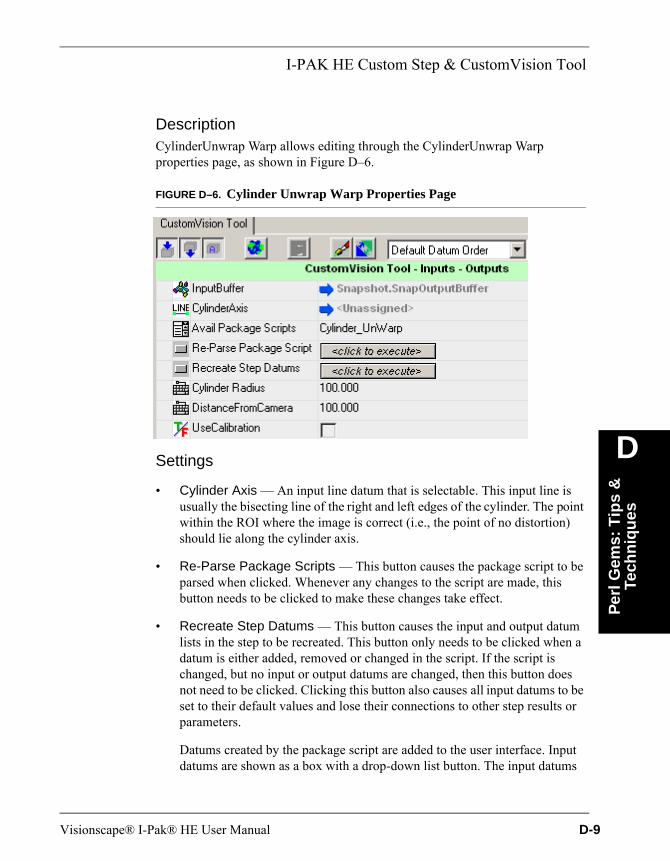
I-PAK HE Custom Step & CustomVision Tool
Per
l Gem
s: T
ips
&
Tech
niq
ues
D
DescriptionCylinderUnwrap Warp allows editing through the CylinderUnwrap Warp properties page, as shown in Figure D–6.
FIGURE D–6. Cylinder Unwrap Warp Properties Page
Settings
• Cylinder Axis — An input line datum that is selectable. This input line is usually the bisecting line of the right and left edges of the cylinder. The point within the ROI where the image is correct (i.e., the point of no distortion) should lie along the cylinder axis.
• Re-Parse Package Scripts — This button causes the package script to be parsed when clicked. Whenever any changes to the script are made, this button needs to be clicked to make these changes take effect.
• Recreate Step Datums — This button causes the input and output datum lists in the step to be recreated. This button only needs to be clicked when a datum is either added, removed or changed in the script. If the script is changed, but no input or output datums are changed, then this button does not need to be clicked. Clicking this button also causes all input datums to be set to their default values and lose their connections to other step results or parameters.
Datums created by the package script are added to the user interface. Input datums are shown as a box with a drop-down list button. The input datums
Visionscape® I-Pak® HE User Manual D-9
Appendix D Perl Gems: Tips & Techniques
can be linked to other similar type datums in the Job. Clicking the drop-down list button causes the Job Tree to be displayed, allowing you to select the datum to link to the input datum. Resource datums are shown as user-editable boxes that can be set to a value directly. Output datums are not shown in the user interface for this step, but can be seen in the Job Tree that comes up when linking an input datum.
• Cylinder Radius — The radius of the cylinder.
• DistanceFromCamera — The distance from the camera to the cylinder.
• UseCalibration — If the inputs (CylinderRadius, DistanceFromCamera) are specified in calibrated/world coordinates (for example, millimeters), then the UseCalibration checkbox should not be checked. If the inputs are specified in pixel coordinates, then UseCalibration should be checked.
TrainingNone.
Results
• Status — Set to true after a successful execution of the step.
• CylUnwrapped Image — The modified image.
I/O SummaryNone.
Dynamic_Binarize
Theory of OperationThe Dynamic Binarize script is used when you want to binarize your image, which means to convert all of the pixels below a threshold to 0 and all those above the threshold to 255. This script will dynamically calculate its binary threshold each time it runs.
Using Dynamic_BinarizeThis script provides you with an ROI like any other Vision tool in Visionscape® would. You can position and size the ROI over any area of your image, and an output buffer will be created of the same width and height, and containing the
D-10 Visionscape® I-Pak® HE User Manual
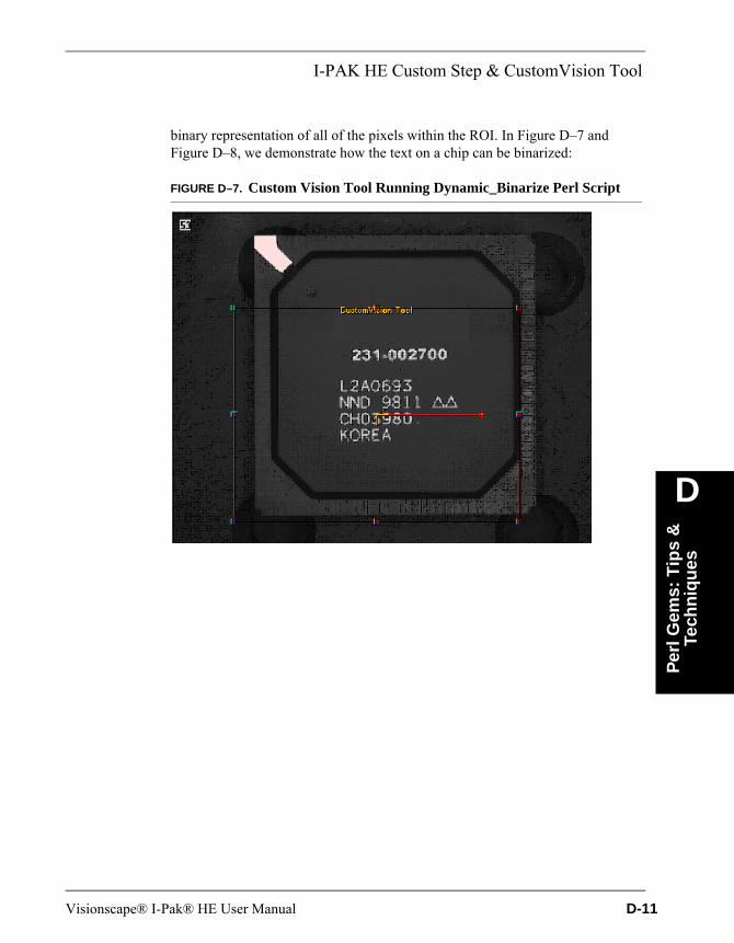
I-PAK HE Custom Step & CustomVision Tool
Per
l Gem
s: T
ips
&
Tech
niq
ues
D
binary representation of all of the pixels within the ROI. In Figure D–7 and Figure D–8, we demonstrate how the text on a chip can be binarized:
FIGURE D–7. Custom Vision Tool Running Dynamic_Binarize Perl Script
Visionscape® I-Pak® HE User Manual D-11
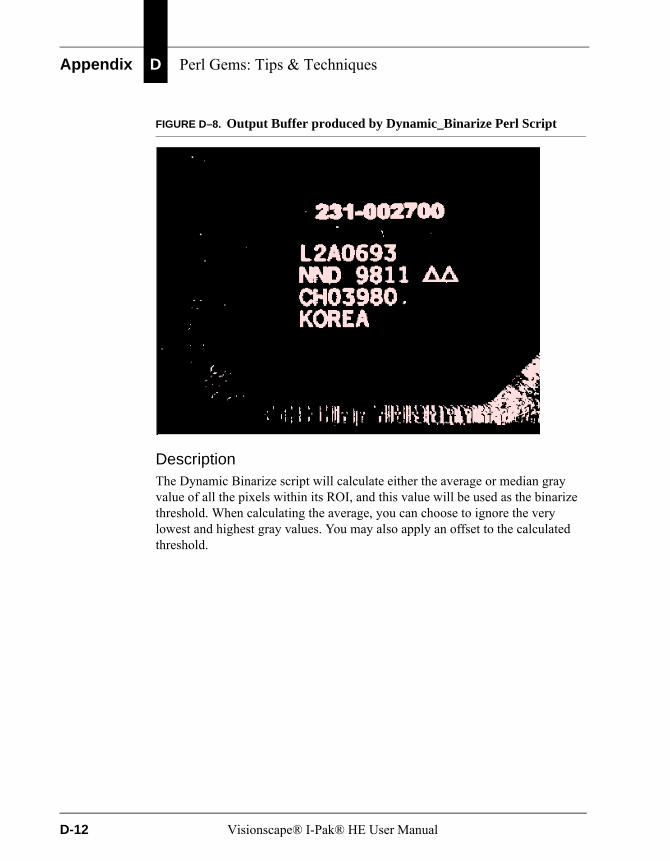
Appendix D Perl Gems: Tips & Techniques
FIGURE D–8. Output Buffer produced by Dynamic_Binarize Perl Script
DescriptionThe Dynamic Binarize script will calculate either the average or median gray value of all the pixels within its ROI, and this value will be used as the binarize threshold. When calculating the average, you can choose to ignore the very lowest and highest gray values. You may also apply an offset to the calculated threshold.
D-12 Visionscape® I-Pak® HE User Manual
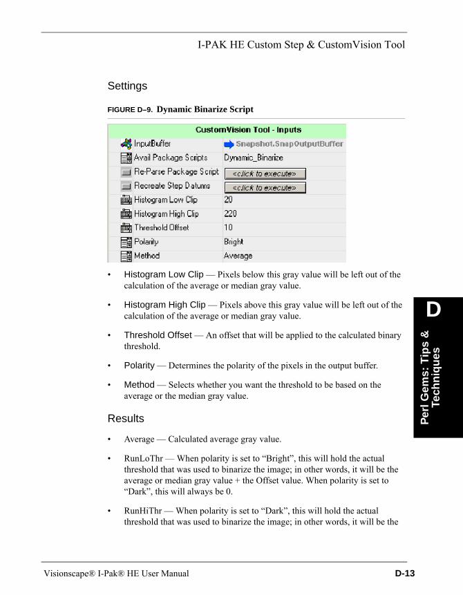
I-PAK HE Custom Step & CustomVision Tool
Per
l Gem
s: T
ips
&
Tech
niq
ues
D
Settings
FIGURE D–9. Dynamic Binarize Script
• Histogram Low Clip — Pixels below this gray value will be left out of the calculation of the average or median gray value.
• Histogram High Clip — Pixels above this gray value will be left out of the calculation of the average or median gray value.
• Threshold Offset — An offset that will be applied to the calculated binary threshold.
• Polarity — Determines the polarity of the pixels in the output buffer.
• Method — Selects whether you want the threshold to be based on the average or the median gray value.
Results
• Average — Calculated average gray value.
• RunLoThr — When polarity is set to “Bright”, this will hold the actual threshold that was used to binarize the image; in other words, it will be the average or median gray value + the Offset value. When polarity is set to “Dark”, this will always be 0.
• RunHiThr — When polarity is set to “Dark”, this will hold the actual threshold that was used to binarize the image; in other words, it will be the
Visionscape® I-Pak® HE User Manual D-13
Appendix D Perl Gems: Tips & Techniques
average or median gray value - the Offset value. When polarity is set to “Bright”, this will always be 255.
• Median — The calculated median gray value.
• ComputedGray — This is the computed gray value that was combined with the offset value to produce the threshold. In other words, if the selected “Method” was “Average”, this will be equivalent to the Average output datum, and if the selected “Method” was “Median”, this will be equivalent to the Median output datum.
FailCodeThe FailCode script does not draw any graphics nor does it need an ROI, so it is best used with the Custom Step rather than the Custom Vision Tool. See “FailCode” starting on page D-3.
FindRotatedThe FindRotated script allows you to run the correlation algorithm over a range of angles, allowing you to find features that will rotate by more than 5° from the trained orientation. The Template Find step in Visionscape® runs the correlation algorithm, but typically can only find features that will rotate by no more than ±5°.
Using FindRotatedFindRotated is used in the same way that the Template Find step is used. You will be provided with two ROIs:
• The first ROI represents the template you wish to train on.
• The second ROI represents the search area (the area within which you will search for the template).
You must train this step before you can use it.
Insert a Custom Vision tool into your Job, and then select the Find Rotated script. You should see two ROIs in your image that look something like the ones in Figure D–10 and Figure D–11:
D-14 Visionscape® I-Pak® HE User Manual
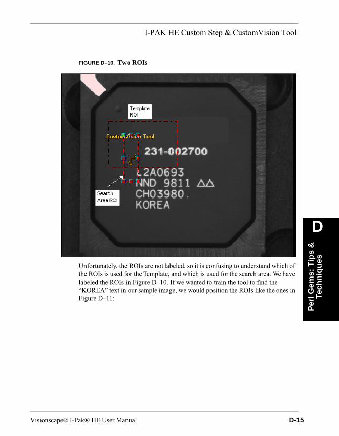
I-PAK HE Custom Step & CustomVision Tool
Per
l Gem
s: T
ips
&
Tech
niq
ues
D
FIGURE D–10. Two ROIs
Unfortunately, the ROIs are not labeled, so it is confusing to understand which of the ROIs is used for the Template, and which is used for the search area. We have labeled the ROIs in Figure D–10. If we wanted to train the tool to find the “KOREA” text in our sample image, we would position the ROIs like the ones in Figure D–11:
Visionscape® I-Pak® HE User Manual D-15

Appendix D Perl Gems: Tips & Techniques
FIGURE D–11. Positioning ROIs to Find KOREA
Press the Train button to train the template.
DescriptionThe FindRotated script will search for the trained template by searching over a specified range of angles specified by the Maximum Search Angle and Minimum Search Angle datums. It accomplishes this by warping the image contents inside of its ROI. It will start by warping the image contents by the angle specified by the Minimum Search Angle datum, and then it will run correlation on the result. All qualifying match locations are recorded, and then the angle is incremented by an amount equal to the value specified in the Angle Step Size datum, and the image is warped and searched again. It will continue in this fashion until it reaches the angle value specified in the Maximum Search Angle datum, and then it will stop. Then, the script will scan through all of the qualifying template locations, and choose the best one.
D-16 Visionscape® I-Pak® HE User Manual
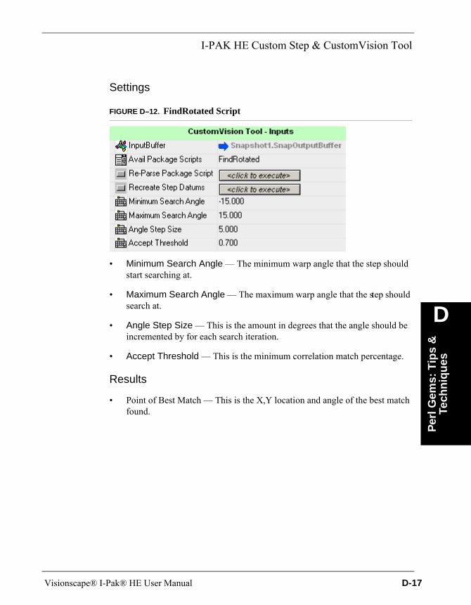
I-PAK HE Custom Step & CustomVision Tool
Per
l Gem
s: T
ips
&
Tech
niq
ues
D
Settings
FIGURE D–12. FindRotated Script
• Minimum Search Angle — The minimum warp angle that the step should start searching at.
• Maximum Search Angle — The maximum warp angle that the step should search at.
• Angle Step Size — This is the amount in degrees that the angle should be incremented by for each search iteration.
• Accept Threshold — This is the minimum correlation match percentage.
Results
• Point of Best Match — This is the X,Y location and angle of the best match found.
Visionscape® I-Pak® HE User Manual D-17

Appendix D Perl Gems: Tips & Techniques
D-18 Visionscape® I-Pak® HE User Manual
Index
Symbols.cal File 6-7.text Component 6-25
Numerics0101
programmer default password 6-1, 6-2, 6-4, 7-13
1010supervisor default password 6-1, 6-2, 6-4,
7-1321 CFR Part 11 xviii, 3-1
access levelsdefined 3-2
administrator 3-4default password 3-4, 6-91default user name 3-4, 6-91
areas of concern 3-19audit trail 3-2
turning on 3-6configuration 3-6, 6-91
files 3-2enabled
operator can perform change lot 6-11end of batch reports 3-7jobs 3-1reconciliation of configuration files 3-12statistics files 3-2support 1-6
5-port Ethernet Switch B-1
AA4 Format 6-95Accept Threshold D-17Access Level Menu
changechange lot password 6-4password 6-4
configure supervisor access 6-5operator 6-4programmer 6-4supervisor 6-4
Access Levelsdefined 3-2
Acquirebutton
train and tryout 6-23tab C-3
Adaptivethreshold method
dot-peen or inkjet 4-28thresholding 4-53, 4-56
Adda new user button 3-15inspection 1 no snapshot 6-52
Advanced Settings 6-42button 6-42, C-3close advanced 6-98create a product 6-43edit tool set 6-95product settings 6-56save product 6-54system settings 6-63tool settings 6-96windows explorer 6-97
AIM Print Verification 4-35Allow
outlined cells 4-29severe damage 4-29
Visionscape® I-Pak® HE User Manual Index-1
Index
steep angle 4-29Allowed
movement inx 5-29, 5-69y 5-29, 5-69
overlap during read 5-42, 5-52, 5-106thickening of symbol 5-39, 5-48, 5-60thinning of symbol 5-39, 5-49, 5-60
Alt+c 7-6+esc
preventing getting to desktop 3-20+f 7-3+number of camera 7-2+s 7-6
Always Ask To Save Font 5-8Angle
step size D-16, D-17variation 4-26
Appearance Flaw Break Test 5-32, 5-71Apply
automatic mincontrast 5-23, 5-48, 5-59sharpness 5-23, 5-48, 5-59
symbol group settings 5-62to
all fontsymbols 5-35default symbol 5-35
Archivepath 6-72pdfs 3-11
Archive/Restore Buttonand pre-programmed products 6-11enabling 6-72ocvfonts 6-16
Archiving Products 6-14ASCII Setup 6-30Assisted Learn 4-20, 4-23, 4-33Audit Trail
andalarms 3-22failed login 3-20login violation 3-5overruns 3-22sluggish updates to it 3-12statistics file 3-21
decrypted 3-8
display button 3-18enable configuration file 6-91resetting 3-12safety 3-20translation 3-9was it compromised? 3-20what it is 3-2
Auto Thresholdadjustment 5-33, 5-52, 5-73enabled 5-33, 5-34, 5-73, 5-74
Auto Thresholdingenabled 5-25, 5-63, 5-64
AutoFind 5-5, 5-35and
lot changeover 5-90ocv tool 6-73
pin 1 index 5-38, 5-48, 5-58pin 2 index 5-39, 5-48, 5-58registration method 5-36
AutoFontand scaling button 5-8button 5-16, 5-18
Automaticbackup of jobs 6-14font selection 5-16, 5-18open softkeyboard 6-94segmentation 5-24, 5-105
computepolarity 5-64enabling 5-22layout step 5-11, 5-24ocvfont tool 5-21ocvruntimetool 5-21when not to use 5-50
threshold adjustment 5-42, 5-52training for multiple ocv
font tools 6-87fontless tools 6-87
Automatically Settingtool settings 6-25
AutoSave Product Definition After Re-Training 6-84
AutoStepbutton
train and tryout 6-20mode
completing 6-19on automatically in train and tryout 6-84
Index-2 Visionscape® I-Pak® HE User Manual
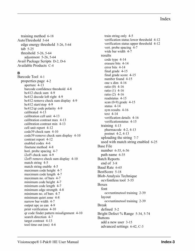
Index
training method 6-18AutoThreshold 5-64
edge energy threshold 5-26, 5-64tab 5-25threshold 5-26, 5-64
adjustment 5-26, 5-64Avail Package Scripts D-2, D-6Available Products C-4
BBarcode Tool 4-1
properties page 4-2aperture 4-13barcode confidence threshold 4-8bc412 check sum 4-9bc412 decode left right 4-9bc412 remove check sum display 4-9bc412 start/stop 4-9bc412/qr code polarity 4-9calibrated 4-13calibration cell unit 4-13calibration contrast max 4-13calibration contrast min 4-13cell unit report 4-12code39 check sum 4-10code39 remove check sum display 4-10contrast report 4-12enabled codes 4-6finetune method 4-8hori. probe spacing 4-7i2of5 check sum 4-9i2of5 remove check sum display 4-10match string 4-5match string enable 4-5maximum code height 4-7maximum code length 4-7maximum no. of bars 4-7minimum code height 4-7minimum code length 4-7minimum edge strength 4-8minimum no. of bars 4-7minimum quiet zone 4-8narrow bar width 4-7output upc as ean 4-9print verification 4-10qr code finder pattern misalignment 4-10search direction 4-7target contrast 4-13tool time out (ms) 4-6
train string only 4-5verification status lower threshold 4-12verification status upper threshold 4-12vert. probe spacing 4-7wide bar width 4-7
resultscode type 4-14erasure bits 4-14error bits 4-14final grade 4-15final grade score 4-15number found 4-15one x dim 4-16ratio (0) 4-16ratio (1) 4-16ratio (2) 4-16readstatus 4-15scan (0-9) grade 4-15status 4-14sym results 4-16text 4-14verification details 4-16verificationstatus 4-15
training 4-13pharmacode 4-2, 4-13postnet 4-2, 4-13
uploading the string 7-7used with match string enabled 6-25
Base Filenumber 6-35, 6-36path name 6-35
Batch Reportsend of 3-8
Baud Rate 6-65BestScore 5-18Blob-Analysis Technique
ocvfontless tool 5-55Boxes
fontocvruntimetool training 2-39
layoutocvruntimetool training 2-39
Breakdefined 5-2
Bright Defect % Range 5-34, 5-74Buttons
add a new user 3-15advanced settings 6-42, C-3
Visionscape® I-Pak® HE User Manual Index-3
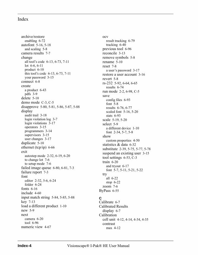
Index
archive/restoreenabling 6-72
autofont 5-16, 5-18and scaling 5-8
camera results 7-7change
all tool’s code 6-13, 6-73, 7-11lot 6-6, 6-11product 6-10this tool’s code 6-13, 6-73, 7-11your password 3-15
connect 6-8create
a product 6-43pdfs 3-9
delete 5-10demo mode C-3, C-5disapprove 5-80, 5-81, 5-86, 5-87, 5-88display
audit trail 3-18login violation log 3-7login violations 3-17operators 3-15programmers 3-14supervisors 3-15user changes 3-17
duplicate 5-10ethernet (tcp/ip) 6-66exit
autostep mode 2-32, 6-19, 6-20to change lot 7-6to setup mode 7-6
failed image queue 6-80, 6-81, 7-3failure report 7-3font
editor 2-32, 5-6, 6-24folder 6-24
fonts 6-16include 4-60input match string 5-84, 5-85, 5-88key 7-13load a different product 1-10new 5-9next
camera 6-20tool 6-96
numeric view 4-67
ocvresult tracking 6-79tracking 6-40
previous tool 6-96reconcile 3-13remove symbols 5-8rename 5-10reset 7-8
a user’s password 3-17restore a user account 3-16revert 5-8rs-232 5-92, 6-64, 6-65
results 6-74run mode 2-2, 6-98, C-5save
config files 6-93font 5-8results 6-76, 6-77scaled font 5-16, 5-20stats 6-93
scale 5-19, 5-20select 5-9
a different device 1-10font 2-34, 5-7, 5-8
showcustom properties 4-50
statistics & data 6-32substitute 2-39, 5-75, 5-77, 5-78suspend an existing user 3-15tool settings 6-53, C-3train 6-20
and tryout 6-17font 5-7, 5-11, 5-21, 5-22
tryall 6-22stop 6-22
zoom 7-6ByPass 6-55
CCalibrate 6-7Calibrated Results
display 6-7Calibration
cell unit 4-12, 4-14, 4-34, 4-35contrast
max 4-12
Index-4 Visionscape® I-Pak® HE User Manual
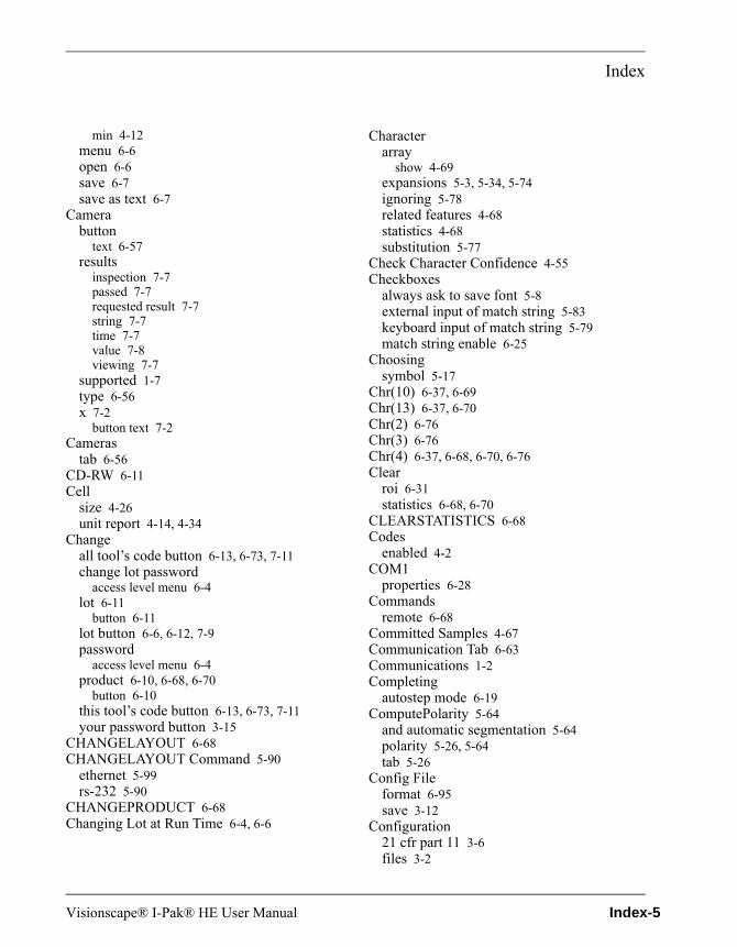
Index
min 4-12menu 6-6open 6-6save 6-7save as text 6-7
Camerabutton
text 6-57results
inspection 7-7passed 7-7requested result 7-7string 7-7time 7-7value 7-8viewing 7-7
supported 1-7type 6-56x 7-2
button text 7-2Cameras
tab 6-56CD-RW 6-11Cell
size 4-26unit report 4-14, 4-34
Changeall tool’s code button 6-13, 6-73, 7-11change lot password
access level menu 6-4lot 6-11
button 6-11lot button 6-6, 6-12, 7-9password
access level menu 6-4product 6-10, 6-68, 6-70
button 6-10this tool’s code button 6-13, 6-73, 7-11your password button 3-15
CHANGELAYOUT 6-68CHANGELAYOUT Command 5-90
ethernet 5-99rs-232 5-90
CHANGEPRODUCT 6-68Changing Lot at Run Time 6-4, 6-6
Characterarray
show 4-69expansions 5-3, 5-34, 5-74ignoring 5-78related features 4-68statistics 4-68substitution 5-77
Check Character Confidence 4-55Checkboxes
always ask to save font 5-8external input of match string 5-83keyboard input of match string 5-79match string enable 6-25
Choosingsymbol 5-17
Chr(10) 6-37, 6-69Chr(13) 6-37, 6-70Chr(2) 6-76Chr(3) 6-76Chr(4) 6-37, 6-68, 6-70, 6-76Clear
roi 6-31statistics 6-68, 6-70
CLEARSTATISTICS 6-68Codes
enabled 4-2COM1
properties 6-28Commands
remote 6-68Committed Samples 4-67Communication Tab 6-63Communications 1-2Completing
autostep mode 6-19ComputePolarity 5-64
and automatic segmentation 5-64polarity 5-26, 5-64tab 5-26
Config Fileformat 6-95save 3-12
Configuration21 cfr part 11 3-6files 3-2
Visionscape® I-Pak® HE User Manual Index-5
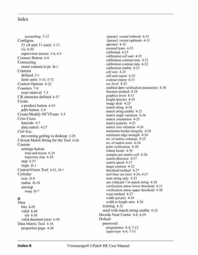
Index
reconciling 3-12Configure
21 cfr part 11 users 3-13i/o 6-59supervisor access 3-6, 6-5
Connect Button 6-8Connecting
smart camera to pc B-1Contrast
defined 5-1limit units 5-33, 5-72
Control Options 6-22Counters 7-8
reset interval 7-5CR character defined 6-37Create
a product button 6-43pdfs button 3-9
Create/Modify OCVFonts 5-5Criss Cross
barcode 4-7data matrix 4-27
Ctrl+Escpreventing getting to desktop 3-20
Current Match String for the Tool 6-26Custom
settings buttontrain and tryout 6-24trajectory step 6-24
step 6-51steps D-1
CustomVision Tool 6-51, D-1Cylinder
axis D-9radius D-10unwrap
warp D-7
DData
bits 6-65valid 6-60
tab 6-58valid duration (ms) 6-58
Data Matrix Tool 4-18properties page 4-20
{param} verstat lothresh 4-31{param} verstat upthresh 4-31aperture 4-32assisted learn 4-23calibrated 4-23calibration cell unit 4-32calibration contrast max 4-31calibration contrast min 4-32calibration enable 4-23cell size 4-25cell unit report 4-32contrast report 4-31ecc level 4-25enabled dpm verification parameters 4-30finetune method 4-28graphics level 4-31height (pixels) 4-24image style 4-25match string 4-24match string enable 4-23matrix angle variation 4-26matrix orientation 4-25matrix polarity 4-25matrix size variation 4-26minimum border integrity 4-26minimum edge strength 4-26no. of matrix columns 4-25no. of matrix rows 4-24print verification 4-30robust locate 4-30samples per matrix cell 4-26search direction 4-27search speed 4-27target contrast 4-32threshold method 4-27tool time out (ms) 4-24, 4-27train string only 4-23use wildcard ? in match string 4-24verification status lower threshold 4-31verification status upper threshold 4-30warp method 4-27width (pixels) 4-24width to height ratio 4-26
training 4-32used with match string enable 6-25
Decode Near Center 4-8, 4-29Default
passwordprogrammer 6-4, 7-13supervisor 6-4, 7-13
Index-6 Visionscape® I-Pak® HE User Manual
Index
unique 7-9DefaultFont.ocv 5-9DefaultSymb Tab 5-27DefaultSymbol 5-105Delay 6-22Delete
button 5-10training 4-71
Demo Mode C-1access password C-3and failed image queue C-2button C-3, C-5disabling C-5
Demonstration Time for Each Product C-4Desktop
enable 3-20Device
select a different 1-10Difference
average spacing 4-36reflectance 4-36
Dilation 5-3, 5-34, 5-74Disapprove
button 5-75, 5-78, 5-80, 5-81, 5-86, 5-87, 5-88Discovery
smart camera 1-10Display
audit trail button 3-18calibrated results 6-7failed image queue 7-3login violation log button 3-7login violations button 3-17numeric (ocrtrainable font tool) 4-67operators button 3-15programmers button 3-14supervisors button 3-15user changes button 3-17
DistanceFromCamera D-10Do Acquire 6-22Download
of match string 6-63of ocvfont tool string 6-63
DPM Print Verification 4-39Duplicate Button 5-10Dynamic_Binarize D-10DynamicMask 5-75
DynamMask Tool 5-62
EEdge Energy Threshold 5-26, 5-33, 5-34, 5-64,
5-74Edit
code 6-13, 7-11tool set 6-51
Enablechange lot in run mode 6-94, 7-6configuration file audit trail 6-91demonstration mode C-4desktop 3-20, 6-94end batch functionality 6-91failed image queue 6-80
disable for demo mode C-2i-pak he
to be minimized 2-2, 6-94mask output 5-40, 5-50, 5-62match string 4-5, 4-19, 4-20ocv failure tracking 6-40, 6-79RS-232 runtime results 6-74, 6-76saving stats and config files from stats
menu 6-93tryout debug info 5-61user
logins for training approvals 6-92, 7-9name access (enable part 11) 3-3, 3-4, 6-91,
7-13user logins for training approvals 6-93
Enabledcodes 4-2, 4-13
Endbatch 6-91, 7-15of batch reports 3-8
Ensure Within ROI 4-29ENTERRUNMODE 6-68ENTERSETUPMODE 6-68EOT 5-99, 6-68, 6-76
character defined 6-37Erosion 5-3, 5-34, 5-74Ethernet
(tcp/ip) button 6-66commands 6-68
ETX 6-76
Visionscape® I-Pak® HE User Manual Index-7
Index
Event Selectoropen 6-9
Exitautostep mode button 2-32, 6-19, 6-20to
change lot 7-6setup mode 7-6
training to main setup button 6-19, 6-24Exiting Run Mode 7-13External
communications timeout 5-85, 6-89input of match string 5-82, 5-83, 5-84, 6-88
FFail
counter 6-51FailCode D-3Failed
image queue 7-3vs. save images 7-3
image queue button 6-80, 6-81, 7-3login attempts
set number of 3-22Failure
report button 7-3FDA xviiFeatExtract Agent 4-50Features
character related 4-68Field
delimiter char 6-65File Menu 6-3Fill ROI 6-31Filter Bright Defects 5-3, 5-34, 5-74Final
residuelargest blob 5-2limit 5-29, 5-31, 5-35, 5-69, 5-70, 5-105max blob size 5-31, 5-71method 5-30, 5-31, 5-70, 5-71total count 5-2
Find Symbols That Touch ROI 5-58FindRotated D-14Finish Button 6-19Font
box 2-39displaying properties 5-7
editor button 2-32, 4-56, 5-6ocvfont tool 6-24ocvruntimetool 6-24
folder buttonocrtrainablefont tool 6-24
scaling 5-19and re-sampling 5-19
selectionautomatic 5-16, 5-18
training 2-32new 5-10
Font Managerdelete button 5-10duplicate button 5-10new button 5-9rename button 5-10select button 5-9
fontname.nna 4-50fontname.nnc 4-50fontname.nnd 4-50Fonts
button 6-16creating 5-6location of stored 5-5modifying 5-6
FontSymbol 5-3, 5-27appearance flaw break test 5-32apply to
all fontsymbols 5-35default symbol 5-35
auto thresholdadjustment 5-33enabled 5-33
bright defect % range 5-34character expansions 5-34edge energy threshold 5-34filter bright defects 5-34final residue
limit 5-31max blob size 5-31method 5-30
initial residue limit 5-30legibility 5-29manual threshold 5-33, 5-34, 5-73, 5-74maximum flaw size 5-31min appear. flaw break size 5-32
Index-8 Visionscape® I-Pak® HE User Manual
Index
minimum allowedcontrast 5-33sharpness 5-32
num of on pixels in template 5-29output mask type 5-35polarity 5-29residue limit units 5-29sharpness limit units 5-32
Forgotten Password 7-14resetting a user’s password 3-17using 21 cfr part 11 7-14
Formatconfig file 6-95
Four-Camera Default I/O Scheme 6-60Functional Specifications 1-4
GGeneral Tab 6-90Go
directly between run mode and training 6-84to
run mode 6-68, 6-70setup mode 6-68, 6-70
Graphicslevel 5-41, 5-50, 5-62
Groupmax pixels 5-61min pixels 5-61properties 5-62
HHawkEye
discovery 1-10HeartBeat 6-61
and plc monitoring 6-61Height 4-27Help
i/o debug 6-8menu 6-8
Histogramhigh clip D-13low clip D-13show 4-69show font 4-69
Horizontal 4-7, 4-27then vertical 4-7, 4-27
Hub B-1
II/O
data valid 6-60device type 6-59tab 6-58
IAQG Print Verification 4-38ID
checking 2-37, 5-21, 5-24, 5-105test determination pct 5-24, 5-105
IGN 2-39, 5-77, 5-78Ignore
extra layout symbols when input is smaller 6-73
single edges 4-28IGNORE Character 6-13Ignoring
character 5-78Image
file name 6-35menu 6-7upload
set the max rate per second 6-83, C-2Include Button 4-60Individual Symbol
search x 5-29, 5-40, 5-49, 5-60, 5-69, 5-106search y 5-29, 5-40, 5-49, 5-61, 5-69, 5-106
Initial Residuedefined 5-2limit 5-29, 5-30, 5-69
Inputchannel 5-92, 5-100, 6-30, 6-63
RS-232 6-27line n 5-80, 5-85match string button 5-84, 5-85, 5-88
Inspectionhow it can fail 5-37, 5-46, 5-55ocv 5-1passed 6-61results
storing 1-7steps without snapshots 6-52trigger 6-61
InspectionResults.dat 6-78, 6-79IntelliFind
and memory limitations on smart camera6-98
Visionscape® I-Pak® HE User Manual Index-9

Index
cameras you can use with 1-1Intensity Enhance 4-28Interface
user 1-7Interval Counters 7-8
reset 7-5IO Debug 6-8I-PAK Administrator
audit trail 3-2can view security file 3-7configuration files 3-2overview 3-4password 3-4reset audit trail 3-12right to re-train 3-6user accounts 3-14
I-PAK HEenclosure standard 6-65selectable main port 6-65shutdown procedure 1-13shutting down 6-98start-up procedure 1-10start-up sequence A-5system name 6-95
ipak.usrstores 21 cfr part 11 info 1-xviii, A-5
ISO Print Verification 4-37
JJob
defined 1-8Jobs 3-1
folder location 6-14JobsBackup 6-14
KKey Button 7-13Keyboard 6-27
input of match string 5-78, 5-79, 6-89Keys
moving & sizing tools 1-7
LLayout
box 2-39step property tab 5-22
Layout Stepautomatic segmentation 5-11, 5-24
LayoutStepallowed overlap during read 5-106automatic segmentation 5-24automatic threshold adjustment 5-42, 5-52min read match % 5-42, 5-52min symbol size 5-25num border spaces to add 5-25ocvfont tool
allowed overlap during read 5-42ocvruntime tool
allowed overlap during read 5-52selected font 5-42, 5-51tab 5-13, 5-24
Learnassisted 4-23
Legibility (%) 5-29, 5-69LF character defined 6-37Lighting 6-57Limitations
memory 6-98Live Button
train and tryout 6-23Load
a different product 1-10images from file
demo mode C-3software systems 1-9
Localhost name 6-67ip address 6-67port number 6-67
Locationjobs folder 6-14stored fonts 5-5
Login 7-13attempts
set number of failed 3-22user 3-4
Loop 6-22Lot ChangeOver
rs-232 5-90
Index-10 Visionscape® I-Pak® HE User Manual

Index
MMain
comm port 6-65Manual Threshold 5-33, 5-34, 5-73, 5-74Mask Number of Dilations 5-40, 5-50, 5-62Masking Tool 6-31Master Font 5-4, 5-45Match String 5-82, 6-25, 6-88
downloading 6-63enable 4-13, 4-24, 6-25, 6-92
used with barcode tool 6-25used with data matrix tool 6-25used with ocrtrainablefont tool 6-25
external input 5-82mismatch action 5-83, 6-89value 4-5
Matrixorientation 4-26polarity 4-33size variation 4-26
Maxcontrast % difference 5-39, 5-49, 5-60flaw size 5-105residue blob 5-30, 5-70
Maximumflaw size 5-31, 5-35, 5-70, 5-71search angle D-16, D-17
Memorylimitations 6-98
Menuscalibration 6-6file 6-3help 6-8image 6-7setup mode 6-3streamlining 6-94
Minappear. flaw break size 5-32, 5-72read match % 5-42, 5-52, 5-106symbol size 5-25symbol size in pixels 5-55, 5-58
Minimumallowed
contrast 5-33, 5-72, 5-73sharpness 5-32, 5-72
quiet zone 4-8
search angle D-16, D-17Mirror 4-25Mismatch
action 5-84strings are different 5-87
Modesrun 2-2setup 2-2
Moving Tools 1-7
NNew
button 5-9match string entry mode 6-26
new.nnd 4-50Next
buttontrain and tryout 6-20
camera button 6-20tool button 6-96
Noactivity limit 3-4, 3-7quiet zone clutter 4-28
No. of Matrixcolumns 4-33rows 4-33
none Script D-2, D-6NPt Locator 4-19Num
border spaces to add 5-25of border spaces to add 5-59, 5-111of on pixels in template 5-29, 5-68
Numberbase file 6-35, 6-36of images in queue 6-81, 7-4
Numericdisplay 4-67view button 4-67
OOCR Training 4-56OCRTrainableFont Tool 4-49
font folder button 6-24properties page
adaptive thresholding 4-53, 4-56allow overlapped characters 4-53allow segmented characters 4-53
Visionscape® I-Pak® HE User Manual Index-11
Index
character fills entire roi 4-53check character confidence 4-53collect all character segments 4-53discard boundary characters 4-54discard boundary segments 4-54edge energy threshold 4-54graphics level 4-54input buffer 4-54limit character height 4-54limit character width 4-54limit the number of characters 4-55min character area 4-55minimum confidence 4-55pass on no data 4-55polarity 4-55selected font(s) 4-56set unknown characters to 4-56threshold 4-56threshold bias 4-56
resultsmaximum character confidence 4-72mean character confidence 4-72minimum character confidence 4-72number of characters found 4-72ocrtf character results 4-73output string 4-72status 4-72
used with match string enable 6-25OCV
inspection 5-1result tracking button 6-79symbols as templates 5-36tips 5-105tracking 6-40
OCVFont 5-3, 5-21apply automatic min
contrast 5-23sharpness 5-23
id test determination pct 5-24shape
positioning 5-17, 5-20show trained symbol shapes 5-24tab 5-23tool
font editor button 6-24OCVFont Tool 5-4, 5-37
autofind pin 1 index 5-36, 5-38autofind pin 2 index 5-36, 5-39
enable mask output 5-40graphics level 5-41individual symbol search x 5-40individual symbol search y 5-40mask number of dilations 5-40runtime id checking 5-40string
downloading 6-63test for character breaks 5-40training 5-79uploading the string 6-25, 7-7use autofind 5-38
OCVFontless Tool 5-4, 5-55apply automatic min
contrast 5-59sharpness 5-59
apply symbol group settings 5-62autofind pin 1 index 5-58autofind pin 2 index 5-58enable
mask output 5-62tryout debug info 5-61
graphics level 5-62individual symbol search x 5-60individual symbol search y 5-61mask number of dilations 5-62min symbol size in pixels 5-58num of border spaces to add 5-59selected symbol group 5-61single ocv symbol step 5-59test for character breaks 5-61tryout debug delay 5-61tutorial 2-3use autofind 5-58
OCVFontscreate/modify 5-5
OCVResultsDm 6-79, 6-80OCVResultsDm Upload 6-79OCVRuntimeTool 5-4, 5-45
apply automatic mincontrast 5-48sharpness 5-48
autofind pin 1 index 5-48autofind pin 2 index 5-48enable mask output 5-50font editor button 6-24
Index-12 Visionscape® I-Pak® HE User Manual
Index
graphics level 5-50individual symbol search x 5-49individual symbol search y 5-49mask number of dilations 5-50runtime id checking 5-50test for character breaks 5-49training 5-79tutorial 2-20use autofind 5-47
OCVSymbolStepappearance flaw break test 5-71auto threshold
adjustment 5-73enabled 5-73
bright defect % range 5-74character expansions 5-74edge energy threshold 5-74filter bright defects 5-74final residue
limit 5-70max blob size 5-71method 5-70
initial residue limit 5-69legibility (%) 5-69manual threshold 5-74maximum flaw size 5-71min appear. flaw break size 5-72minimum allowed
contrast 5-73sharpness 5-72
num of on pixels in template 5-68output mask type 5-75polarity 5-69residue limit units 5-69threshold enabled 5-74
OnScreen Keyboard 3-7, 6-27Open
calibration 6-6event selector 6-9softkeyboard 1-6, 6-9softkeyboard automatically 6-94
Operatorunique default password 6-11
Optical Characterrecognition 4-49verification (ocv) 5-1
Options 6-22button
train and tryout 6-21Output
channel 5-92, 5-100, 6-63mask type 5-35, 5-75
Overdrive 4-27Overruns 6-60, 7-12
PParity 6-65Part Image
queue size 6-35storage mode 6-34, 6-35
Passworddefault 6-4
21 cfr part 11 3-4, 6-91programmer 6-1, 6-2, 6-4, 7-13supervisor 6-1, 6-2, 6-4, 7-13
expires after certain specified time 6-93forgotten 7-14
21 cfr part 11 7-14programmer 6-1supervisor 6-1traditional not used 3-4unique
default 7-9operator 6-11
user 3-4Path Name
base file 6-35PC
registryvalues written to 7-8
requirementsminimum 1-2
sluggish response 3-12supported 1-6
PDFsarchiving 3-11
Perl 6-51, D-1cylinder unwrap warp D-7dynamic_binarize D-10failcode D-3findrotated D-14none script D-2, D-6package script 6-51
Visionscape® I-Pak® HE User Manual Index-13
Index
programming language 6-51Pharmacode
training for barcode tool 4-2, 4-13PLC Monitoring
heartbeat 6-61Polarity 5-26, 5-29, 5-64, 5-69, D-13Position Enhance 4-28Postnet
training for barcode tool 4-2, 4-13Previous
buttontrain and tryout 6-20
Previous Tool Button 6-96Print
verification 4-10, 4-14, 4-15, 4-30, 4-31aim 4-35dpm 4-39iaqg 4-38iso 4-37set to ansi 4-11
Process Overrun 7-12Product
changeover activities 6-71creation 6-43defined 1-8description text 6-11load a different 1-10specifications 1-3
Productsarchiving 6-14restoring 6-14
Programmer 6-98password 6-1
Properties 6-29setting on group basis 5-62
Protocolexternal input of match string 5-89header line 5-89input and output inspection string 5-89input line 5-89inspection string 5-82keyboard input 5-82transmit final layout string 5-89
QQuit Product Creation 6-47
RRandom Access Training 6-19Reconcile Button 3-13Reconciliation of Configuration Files 3-12Recreate Step Datums D-3, D-6, D-9RectWarp 4-19Reflectance
differences in 4-36Registration
method 5-36Remote
commands 6-68details 6-68syntax 6-68
Removefrom font 4-71symbols button 5-8
Rename Button 5-10Re-Parse Package Script D-2, D-6, D-9Report
rs-232 error when inspection result is empty 6-80
Reports21 cfr part 11
end of batch 3-7Requirements
minimum pc 1-2Re-sampling
and font scaling 5-19Reset
a user’s password button 3-17audit trail 3-12button 7-8interval counters 7-5statistics
after re-training 6-84on product changeover 6-50, 6-71
Residue Limit Units 5-29, 5-69set to percentage 5-30, 5-31set to pixels 5-30, 5-31
Restorea user 3-20
account button 3-16Restoring Products 6-14Results
reporting 6-74
Index-14 Visionscape® I-Pak® HE User Manual
Index
storing inspection 1-7to upload 4-11
Retrievestatistics 6-68
RETRIEVESTATS 6-68Retry
by input 5-84, 5-88, 6-89by learning 5-84, 5-88, 6-89
Revert 4-63, 4-64, 5-8ROI
contains property 4-55RS-232 6-28, 6-29, 6-30
button 5-92, 6-64, 6-65commands 6-68results button 6-74
Runmode 2-2, 7-1
button 2-2, 6-98, C-5exiting 7-13window 7-2zooming 7-6
Runtimechange lot
password 21 cfr part 11 active 7-9password 21 cfr part 11 not active 7-9
font 5-45font tool
uploading the string 7-7id checking 5-2, 5-21, 5-40, 5-50, 5-105inspection priority 6-91
SSafety
audit trail 3-20configuration files 3-21jobs files 3-21statistics files 3-21
Samplescommitted 4-67deleting trained 4-71
Savecalibration 6-7calibration as text 6-7config file 3-12config files button 6-93
failure queue images on return to setup 6-80, 6-82
font button 5-8images
vs. failed image queue 6-33results button 6-76, 6-77runtime results to a file 6-76, 6-78scaled font button 5-16, 5-20stats button 6-93
Scale Button 5-19, 5-20Scaling 5-16Scan for Sequence Steps Using Outputs 1-9Score Value 5-18Search Direction 4-6, 4-24security.log 3-7Segment Agent 4-50Segmentation
automaticlayout 5-24layout step 5-11
Selecta different device 1-10button 5-9font button 2-34, 5-7, 5-8results to upload 6-25, 6-74, 6-75, 6-77, 7-7
Selectedfont 5-42, 5-51symbol group 5-61
Sendline ends with line feeds 6-30
Setimage upload max rate per second 6-83, C-2number of failed login attempts 3-21, 3-22,
6-93passwords to expire 3-6, 3-19, 6-93time limit for system inactivity 6-93unknown characters to 4-72
Settingsadvanced 6-42
Setupmode 2-2, 6-1
access levels 3-2drop-down menus 6-3file menu 6-3
Sharpnessdefined 5-2
Visionscape® I-Pak® HE User Manual Index-15
Index
limit units 5-32, 5-72Shortcut A-5Show
all menu options (advanced users) 6-94, 7-3character array 4-69custom properties button 4-50font histogram 4-69full path 7-10, 7-11histogram 4-69i/o results 6-22one tool at a time in train and tryout 6-85only unique codes in change lot setting 6-72stddev array 4-69trained symbol shapes 5-17, 5-20, 5-24
Shutdown Procedure 1-13Shutting Down I-PAK HE 6-98Signature Authority 3-5, 3-20Single
camera default i/o scheme 6-59ocv symbol step 5-59
Sizing Tools 1-7Smart Camera
connecting to pc B-1discovery 1-10
Snapshot 4-19Softkeyboard
open 1-6, 6-9open automatically 6-94
Softwaresystem 1-9validation xviii
Spacingdifference in average 4-36
Specialfeatures
i-pak he tools and steps 6-50training
tools 6-25Specifications
functional 1-4product 1-3system 1-2
Standardoperating procedures 3-5
Start-up Procedure 1-10
Statisticscharacter 4-68file and audit trail 3-21files 3-2
Statistics & Data 6-32button 6-32clear statistics 6-32close statistics 6-42preview data file 6-39preview statistics 6-40save data file 6-33save images 6-33save stats file 6-33transmit statistics 6-37
StdDev Arrayshow 4-69
Steptips 5-43, 5-52, 5-65
Stopbits 6-65
Storeall images 6-34failed images 6-35no images 6-35passed images 6-35
Storinginspection results 1-7
Streamline Menus 6-94Strobe
polarity 6-57STX 6-76Substitute
button 2-39, 5-75, 5-77, 5-78Substitute/Ignore 5-75Substituting
characters 5-77Supervisor 6-98
configure access 3-6, 6-5password 6-1
Supportedcamera 1-7pc 1-6
Suspend An Existing User Button 3-15Switch
5-port ethernet B-1
Index-16 Visionscape® I-Pak® HE User Manual

Index
Symbolchoosing 5-17height 4-14sorting sensitivity 5-59width 4-14
Systemsettings
communication tab 6-63general tab 6-90training and results tab 6-71
specifications 1-2
TTabs
acquire C-3autothreshold 5-25cameras 6-56communications 6-63computepolarity 5-26data valid 6-58defaultsymb 5-27general 6-90i/o 6-58layout 5-24layout step property 5-22layoutstep 5-13ocvfont 5-23training and results 6-71
Target Contrast 4-12TCP/IP 6-30, 6-66
protocol 6-38protocol & syntax 6-38syntax for a multi-camera job 6-39syntax for single-camera job 6-38
Template Method 5-36Test For Character Breaks 5-40, 5-49, 5-61Text
product description 6-11Threshold 4-56, 5-26, 5-64
adjustment 5-26, 5-33, 5-43, 5-52, 5-64method
adaptive 4-28offset D-13
Timeout 6-65external communications 6-89
Tipsfor marking ocr fonts 4-72ocv 5-105step 5-43, 5-52, 5-65training (ocrtrainable font tool 4-71
Toollimit 6-51set
edit 6-51settings
button 6-21, 6-53, C-3setting automatically 6-25
Toolsmoving 1-7sizing 1-7special training of 6-25
Total Residue Area 5-30, 5-70Touch Input Software 1-6Tracking
ocv 6-40Traditional Passwords Not Used 3-4Train
button 6-20train and tryout 6-20
debug delay 5-18, 5-21font button 5-7, 5-11, 5-21, 5-22
Train and Tryout 6-17acquire 6-23autostep 6-20button 6-17custom settings 6-24exit training to main setup 6-24live 6-23next 6-20options 6-21previous 6-20tool settings 6-21toolbar 6-19train 6-20try all 6-24try tool
train and tryout 6-23train and tryout 6-20Trained
samples 4-71
Visionscape® I-Pak® HE User Manual Index-17

Index
Trainingand results tab 6-71barcode tool 4-13data matrix tool 4-32debug delay 5-7delete 4-71font 2-32match string enabled tools 6-25ocr 4-56ocvfont tool 5-79ocvruntimetool 5-79tips
ocrtrainable font tool 4-71Trajectory Step
custom settings 6-24Transmit
finalinspection string 5-83, 5-84, 5-88, 6-89layout string 5-84
statisticsTCP/IP protocol & syntax 6-38
Triggeri/o 6-57overrun 7-12polarity 6-57
Trigger/Acquire Method 6-56Triggered (I/O or Sensor) 6-22Troubleshooting 5-107Try
all button 6-22train and tryout 6-24
stop button 6-22Tryout
debug delay 5-61mode options 6-22
Turbo 4-27Tutorials
ocvfontless tool 2-3ocvruntime tool 2-20
UUndo Include 4-61Uninstalling the Driver A-5Unique Default Password 7-9Update
inspection step(s) with current settings 6-36
Uploadimages from part queue now 6-36
UPS A-6US Letter Format 6-95Use
autofindocvfont tool 5-38ocvfontless tool 5-58ocvruntime tool 5-47
data valid 6-58input mask 5-62input string 5-84, 5-87, 6-89learned string 5-84, 5-87, 6-89onscreen keypad instead of pc keyboard 3-7,
6-94selected font on exit 5-8wildcard ? in match string 6-26
UseCalibration D-10User
defined templates 5-36interface 1-7login 3-4name
default 21 cfr part 11 3-4, 6-91passwords 3-4
VValidation xviiValues Written to PC Registry 7-8Verification
aim print 4-35dpm print 4-39iaqg print 4-38iso print 4-37status
lower threshold 4-15, 4-31upper threshold 4-15, 4-31
Vertical 4-7, 4-27then horizontal 4-7, 4-27
Viewingcamera results 7-7
WWaiting for Input Match String Line N 5-85Width 4-27
to height ratio 4-27Wildcard Match Character 6-26
Index-18 Visionscape® I-Pak® HE User Manual

Index
Windows Explorer 6-97Wizard Training Method 6-18
ZZoom
buttonsdisplaying in run mode 7-6hiding in run mode 7-6
in buttontrain and tryout 6-23
out buttontrain and tryout 6-23
Visionscape® I-Pak® HE User Manual Index-19