Embed Size (px)
Citation preview

AbstractThe method of generating electrical voltage for charging an electronic gadget from the piezoelectric sensor that is fixed to the sole of the footwear is illustrated in this paper.
*Author for correspondence
Indian Journal of Science and Technology, Vol 7(7), 945–948, July 2014ISSN (Print) : 0974-6846
ISSN (Online) : 0974-5645
Charging an Electronic Gadget using Piezoelectricity
J. John Livingston* and M. Hemalatha
School of Computing, SASTRA University, Thanjavur, Tamil Nadu, India; [email protected], [email protected]
1. IntroductionWith the introduction of many handheld portable elec-tronic gadgets, energy harvesting has become one of the fascinating subjects of interest to provide portable electri-cal power. The commonly used sources are: solar power, wind energy and piezoelectricity. This study is focussed on Piezoelectricity as it depends on the mechanical pres-sure or strains to obtain electrical energy, while the other sources are not reliable at all times.
2. Existing Mechanical Energy Harvesters
Some vibration based energy generators that converts mechanical energy to electrical energy that have been suc-cessfully developed are Electromagnetic1, Electrostatic2, Piezoelectric generators3,4.
2.1 Electromagnetic GeneratorWhenever a change in the magnetic flux linked with the coil occurs, an electromagnetic force (emf) is generated across the coil in an electromagnetic generator. The rela-tionship between the emf and the displacement (z) 5 is
where, the constant K is determined by number of turns of the coil, length of the coil, area of the coil and magnetic field intensity.
2.2 Electrostatic GeneratorIt consists of a capacitor whose capacitance (C) changes as a function of displacement (Z). The equation for the electric current flowing in an electrostatic generator5 is given by
where, V represents the voltage that is developed across the capacitor when the capacitor is fully charged, V0 represents the initial value of the voltage across thecapacitor. V0 represents electromechanical coupling and represents the relationship between the current
and the capacitance. When the capacitor is charged with V0 initially then the electromechanical coupling will be high. The polarisation of the capacitor can be achieved by using piezoelectric elements as done in this paper5.
2.3 Piezoelectric GeneratorThere are two effects in piezoelectricity: direct piezoelectric effect and converse piezoelectric effect. Direct piezoelectric
Keywords: Energy Harvesting, Piezoelectricity, Piezoelectric Sensor, Portable Electric Power
emf K dzdt
= (1)
I VdC z
dtC z dV
dt=
( )+
( )0
(2)
dC zdt( )
C z dVdt( )
Charging an Electronic Gadget using Piezoelectricity
Indian Journal of Science and TechnologyVol 7 (7) | July 2014 | www.indjst.org946
effect is the generation of electric charge when mechanical strain is applied on piezoelectric materials; whereas the converse effect is defined as the deformation in the crystal caused, when an electrical voltage is applied to the piezo-electric materials. Direct piezoelectric effect is employed in manufacturing sensors and converse piezoelectric effect is employed in manufacturing actuators. The piezoelectric materials are of natural and also of artificially made. Quartz is a natural piezoelectric material while Lead Zirconate Titanate (PZT) is an artificial piezoelectric material.
The following equation6 describes piezoelectric effect (3) and its converse effect (4).
where, D denotes electric displacement vector, T
denotes stress vector, ƐT denotes dielectric permittiv-ity at constant mechanical stress, sE denotes the matrix for compliance coefficients at constant electric field, S denotes strain vector, d denotes piezoelectric constant matrix, E denotes electric field vector.
In piezoelectric effect, charge density is developed on its surface when external pressure is applied5.
where, D is the charge density, Q is the electric charge
that is accumulated on the surface, A is the area of the conductive electrode.
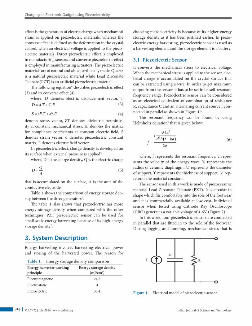
Table 1 shows the comparison of energy storage den-sity between the three generators5.
The table 1 also shows that piezoelectric has more energy storage density when compared with the other techniques. PZT piezoelectric sensor can be used for small scale energy harvesting because of its high energy storage density7.
3. System DescriptionEnergy harvesting involves harvesting electrical power and storing of the harvested power. The reason for
choosing piezoelectricity is because of its higher energy storage density as it has been justified earlier. In piezo-electric energy harvesting, piezoelectric sensor is used as a harvesting element and the storage element is a battery.
3.1 Piezoelectric SensorIt converts the mechanical stress to electrical voltage. When the mechanical stress is applied to the sensor, elec-trical charge is accumulated on the crystal surface that can be extracted using a wire. In order to get maximum output from the sensor, it has to be set in its self-resonant frequency range. Piezoelectric sensor can be considered as an electrical equivalent of combination of resistance R, capacitance C and an alternating current source I con-nected in parallel as shown in Figure 1 6.
The resonant frequency can be found by using Helmholtz equation6 that is given below:
where, f represents the resonant frequency, c repre-sents the velocity of the energy wave, ‘a’ represents the radius of ceramic diaphragm, ‘d’ represents the diameter of support, ‘t’ represents the thickness of support, ‘k’ rep-resents the material constant.
The sensor used in this work is made of piezoceramic material Lead Zirconate Titanate (PZT). It is circular in shape which fits comfortably into the sole of the footwear and it is commercially available at low cost. Individual sensor when tested using Cathode Ray Oscilloscope (CRO) generates a variable voltage of 4-6V (Figure 2).
In this work, four piezoelectric sensors are connected in parallel that are fitted in to the sole of the footwear. During jogging and jumping, mechanical stress that is
D d T T E= +. .
(4)S sE T dt E= +. .
(3)
D QA
= (5)
Table 1. Energy storage density comparisonEnergy harvester working principle
Energy storage density (mJ/cm3)
Electromagnetic 24.8Electrostatic 4Piezoelectric 35.4 Figure 1. Electrical model of piezoelectric sensor.
(6)fc a
d h t ka=
+( )
4
2
2
2
p

J. John Livingston and M. Hemalatha
Indian Journal of Science and Technology 947Vol 7 (7) | July 2014 | www.indjst.org
applied on the sole of the footwear is converted to elec-trical voltage which is given to the electronic gadget (Figure 3). A human while walking exerts about 30W of power on the ground and theoretically out of which 100mW of electrical power is possible to obtain without disturbing the comfort of the person’s walk9.
3.2 Positioning of Piezoelectric SensorPiezoelectric sensors has to be positioned in two main parts of the sole of the shoe where the maximum pressure is applied (Figure 4).
Single sensor is capable of generating 3-5V on appli-cation of pressure consistently, in this work four sensors are connected in parallel in order to increase the prob-ability of getting maximum output.
Piezopolymeric materials are more advantageous to use than piezoceramic materials in case of sensor applica-tion, because polymeric films can be easily fabricated to different shapes. Even then piezoceramic sensor has been used in this work because it is commercially available at low cost (Figure 5).
3.3 Storage deviceThe load that is used for storing the harvested electrical energy is mobile phone battery. Many mobile phones use a battery which is made of the combination of chemicals Lithium-ion “Li-ion” that needs a DC voltage of 3.6V for charging. For power storage it is better to use recharge-able battery than a super capacitor as rechargeable battery has high energy stored per unit weight and a slower dis-charge response10.
4. Experimental ResultsThe necessary voltage required for charging a mobile phone battery is successfully generated and the output is shown in the picture. The output current that is generated from the piezoelectric sensor may be less, which may increase the time taken for charging a battery. But it can be used for charging an electronic device battery for emergency pur-pose where there is no direct source of electricity. This can be used as an efficient source for portable electric power
Figure 2. Piezoelectric sensor tested in CRO.
Figure 3. Piezoelectric energy harvesting process.
Figure 4. Positioning of piezoelectric sensor.
Figure 5. Testing of sensor using multimeter.

Charging an Electronic Gadget using Piezoelectricity
Indian Journal of Science and TechnologyVol 7 (7) | July 2014 | www.indjst.org948
vibration-based electromechanical power generator. Sens Actuators A, Phys. 2001; 92(1–3):335–42.
2. Miyazaki M, Tanaka H, Ono G, Nagano T, Ohkubo N, Kawahara T, Yano K. Electric-energy generation using vari-able capacitive resonator for power-free LSI. Proc ISLPED; 2003. p. 193–98.
3. Keawboonchuay C, Engel TG. Maximum power generation in a piezoelectric pulse generator. IEEE Trans Plasma Sci. 2003; 31(1):123–28.
4. Yang J, Chen Z, Hu Y. An exact analysis of a rectangu-lar plate piezoelectric generator. IEEE Trans Ultrason, Ferroelectr Freq Control. 2007; 54(1):190–95.
5. Rocha JG, Gonçalves LM, Rocha PF, Silva MP, Lanceros-Méndez S. Energy harvesting from piezoelectric materials fully integrated in footwear. IEEE Trans Ind Electron. 2010; 57(3):813–19.
6. PisharodyHarikrishnan G. An optimal design for piezo-electric energy harvesting system. IEEE PES Innovative Smart Grid Technologies- India; 2007.
7. Turner J, Ahmed MN, Ha DS, Mattavelli P. A new approach to the wide bandwidth of piezoelectric transducers for vibration energy harvesting. IEEE. 2010; 1064–67.
8. Kwon D, Rincon-Mora GA. A Rectifier-Free Piezoelectric Energy Harvester Circuit.IEEE. 2009; 1085–88.
9. Han D, Kaajakari V. Microstructured polymer for shoe power generation. Transducers, Denver, CO, USA; 2009.
10. Ali WG, Nagib G. Design Considerations for Piezoelectric Energy Harvesting Systems. 2012 International Conference on Engineering and Technology (ICET); 2012 Oct 10–11. Cairo. IEEE. p. 1–6.
for portable devices. This work is a low cost approach to demonstrate the application of piezoelectric sensor to meet the need for portable electric power (Figure 6).
5. Future ScopeThe analysis of the voltage stored in the battery with respect to the force applied can be done and the efficiency of this work can be calculated.
Efficient storage of the generated voltage can be achieved by using the circuit shown in Figure 7.
An array of piezosensors can be connected in series to get larger output and can be used for higher load appli-cations. A rectifier-free piezoelectric energy harvesting circuit can be used for charging efficiently8. Piezoelectric energy harvesting can be used as a cleanest form of alter-nate energy source in future. This work is an example illustrating one of its applications. It can also be used as an energy source for wearable electronics.
6. References 1. El-hami M, Glynne-Jones P, White M, Hill M, Beeby S,
James E, Brown D, Ross N. Design and fabrication of a new
Figure 6. Experimental Output.
Figure 7. Circuit for efficient energy harvesting.