Embed Size (px)
Citation preview
ISSN (Online) : 2319 – 8753 ISSN (Print) : 2347 - 6710
International Journal of Innovative Research in Science, Engineering and Technology
An ISO 3297: 2007 Certified Organization, Volume 3, Special Issue 1, February 2014
International Conference on Engineering Technology and Science-(ICETS’14)
On 10th & 11th February Organized by
Department of CIVIL, CSE, ECE, EEE, MECHNICAL Engg. and S&H of Muthayammal College of Engineering, Rasipuram, Tamilnadu, India
Copyright to IJIRSET www.ijirset.com 920
Modeling and Control for Smart Grid Integration with MPPT of Solar/Wind Energy
Conversion System S. Sathish Kumar1, B.Swapna2, Dr.C.Nagarajan3
Research Scholar, GRT Institute of Engineering & Technology, Tamilnadu, India1 Assistant Professor, Dept. of EEE, GRT Institute of Engineering & Technology, Tamilnadu, India2
Professor, Dept. of EEE, Muthayammal College of Engineering, Tamilnadu, India3 Abstract- Performance optimization, system reliability and operational efficiency are key characteristics of smart grid systems. In this paper a novel model of smart grid-connected PV/WT hybrid system is developed. It comprises photovoltaic array, wind turbine, asynchronous (induction) generator, controller and converters. The model is implemented using MATLAB/SIMULINK software package. Perturb and observe (P&O) algorithm is used for maximizing the generated power based on maximum power point tracker (MPPT) implementation. The dynamic behavior of the proposed model is examined under different operating conditions. Solar irradiance, temperature and wind speed data is gathered from a grid connected, 28.8kW solar power system located in central Manchester. Real-time measured parameters are used as inputs for the developed system. The proposed model and its control strategy offer a proper tool for smart grid performance optimization. Index Terms-- Control systems, Hybrid power systems, MATLAB, Modeling, PV systems, MPPT, Power electronics, Smart grids, Wind power generation.
I. INTRODUCTION The limitations of global resources of fossil and nuclear fuel, has necessitated an urgent search for alternative sources of energy. Therefore, a new way has to be found to balance the supply and demand without resorting to coal and gas fuelled generators. Smart grid is a system that would enable the integration of renewable energy
sources and shift from reliance on fossil fuels, while maintaining the balance between supply and demand. The key characteristics of smart Grid includes:
Grid optimization: system reliability and operational efficiency.
Distributed generation: not only traditional large power stations, but also individual PV panels, micro-wind, etc.
Advanced metering infrastructure (AMI): smart meters.
Grid-scale storage. Demand response. Plug-in hybrid electric vehicles (PHEVs) and
vehicle to grid (V2G). This paper focuses mainly on the smart grid integration of PV/WT hybrid system (grid optimization and distribution generation). Over recent years several research and investment has been carried out in hybrid power system, such as Yang who recommended an optimal design model for hybrid solar–wind system, which employs battery banks to calculate the system’s optimum configurations in China. Dihrab presented a hybrid solar-wind system as a renewable source of power generation for grid connected application in three cities in Iraq. Reichling modeled a hybrid solar wind power plant in south western Minnesota for a two year period, using hourly solar irradiation and wind speed data. Ekren showed an optimum sizing procedure of PV/wind hybrid system in Turkey. Several modeling studies on PV/WT power system have been conducted. Among them, Kim developed a grid-connected photovoltaic model using
ISSN (Online) : 2319 – 8753 ISSN (Print) : 2347 - 6710
International Journal of Innovative Research in Science, Engineering and Technology
An ISO 3297: 2007 Certified Organization, Volume 3, Special Issue 1, February 2014
International Conference on Engineering Technology and Science-(ICETS’14)
On 10th & 11th February Organized by
Department of CIVIL, CSE, ECE, EEE, MECHNICAL Engg. and S&H of Muthayammal College of Engineering, Rasipuram, Tamilnadu, India
Copyright to IJIRSET www.ijirset.com 921
PSCAD/EMTDC for electromagnetic transient analysis. Tsai implemented an insulation-oriented PV model using MATLAB/SIMULINK software package. Gow developed a general PV model which can be implemented on simulation platforms such as PSPICE or SABER. Khan presented the model of a small wind-fuel cell hybrid energy system and analyzed life cycle of a wind-fuel cell integrated system. Chayawatto developed a mathematical model of a dc/ac full-bridge Switching converter with current control for PV grid connected system under islanding phenomena; this phenomenon occur when the grid system is disconnected for any reason and the distributed generation still supplies to any section of local loads. Onar modeled a hybrid wind/FC/ultra-capacitor (UC) power system for a grid-independent user with appropriate power flow controllers. In this study, a detailed dynamic model, control and simulation of a smart grid-connected PV/WT hybrid power generation system is proposed. Modeling and simulation are implemented using MATLAB/SIMULINK and Sim Power Systems software packages to verify the effectiveness of the proposed system.
II. SYSTEM DESCRIPTION AND MODELING
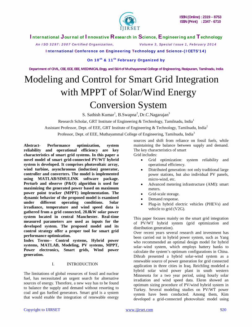
Smart grid is a system consists of three layers: the physical power layer, the control layer and the application layer and according to, Katherine Hamilton, smart grid has to be dynamic and have constant two-way communication, as shown in Fig.1. So, for example, with PV panels on the roofs, intelligent building system will
Fig.1. General Layout of the smart grid
generates, store and use their own energy. Hence, as active buildings they become part of the smart grid. This
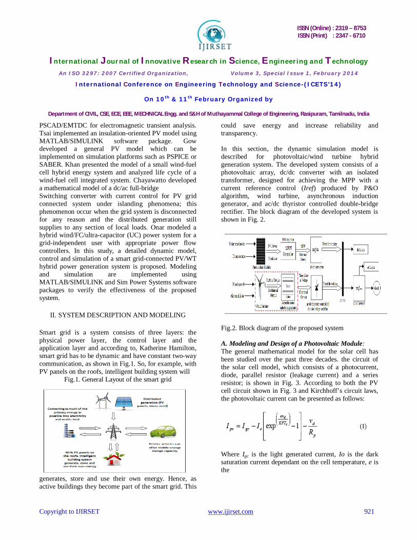
could save energy and increase reliability and transparency. In this section, the dynamic simulation model is described for photovoltaic/wind turbine hybrid generation system. The developed system consists of a photovoltaic array, dc/dc converter with an isolated transformer, designed for achieving the MPP with a current reference control (Iref) produced by P&O algorithm, wind turbine, asynchronous induction generator, and ac/dc thyristor controlled double-bridge rectifier. The block diagram of the developed system is shown in Fig. 2.
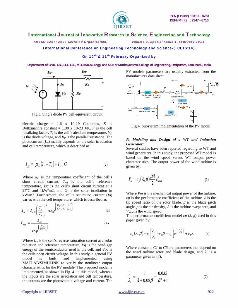
Fig.2. Block diagram of the proposed system A. Modeling and Design of a Photovoltaic Module: The general mathematical model for the solar cell has been studied over the past three decades. the circuit of the solar cell model, which consists of a photocurrent, diode, parallel resistor (leakage current) and a series resistor; is shown in Fig. 3. According to both the PV cell circuit shown in Fig. 3 and Kirchhoff’s circuit laws, the photovoltaic current can be presented as follows:
Where Igc is the light generated current, Io is the dark saturation current dependant on the cell temperature, e is the
ISSN (Online) : 2319 – 8753 ISSN (Print) : 2347 - 6710
International Journal of Innovative Research in Science, Engineering and Technology
An ISO 3297: 2007 Certified Organization, Volume 3, Special Issue 1, February 2014
International Conference on Engineering Technology and Science-(ICETS’14)
On 10th & 11th February Organized by
Department of CIVIL, CSE, ECE, EEE, MECHNICAL Engg. and S&H of Muthayammal College of Engineering, Rasipuram, Tamilnadu, India
Copyright to IJIRSET www.ijirset.com 922
Fig.3. Single diode PV cell equivalent circuit electric charge = 1.6 x 10⁻¹⁹ Coulombs, K is Boltzmann’s constant = 1.38 x 10⁻²³ J/K, F is the cell idealizing factor, Tc is the cell’s absolute temperature, VD is the diode voltage, and RP is the parallel resistance. The photocurrent (Igc) mainly depends on the solar irradiation and cell temperature, which is described as
Where μsc is the temperature coefficient of the cell’s short circuit current, Tref is the cell’s reference temperature, Isc is the cell’s short circuit current at a 25oC and 1kW/m2, and G is the solar irradiation in kW/m2. Furthermore, the cell’s saturation current (Io) varies with the cell temperature, which is described as
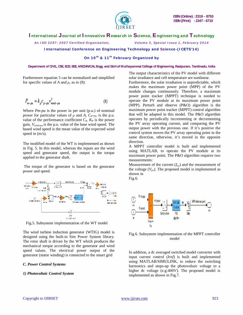
Where Ioα is the cell’s reverse saturation current at a solar radiation and reference temperature, Vg is the band-gap energy of the semiconductor used in the cell, and Voc is the cells open circuit voltage. In this study, a general PV model is built and implemented using MATLAB/SIMULINK to verify the nonlinear output characteristics for the PV module. The proposed model is implemented, as shown in Fig. 4. In this model, whereas the inputs are the solar irradiation and cell temperature, the outputs are the photovoltaic voltage and current. The
PV models parameters are usually extracted from the manufactures data sheet.
Fig.4. Subsystem implementation of the PV model B. Modeling and Design of a WT and Induction Generator: Several studies have been reported regarding to WT and wind generators. In this study, the proposed WT model is based on the wind speed versus WT output power characteristics. The output power of the wind turbine is given by:
Where Pm is the mechanical output power of the turbine, cp is the performance coefficient of the turbine, λ is the tip speed ratio of the rotor blade, β is the blade pitch angle, ρ is the air density, A is the turbine swept area, and Vwind is the wind speed. The performance coefficient model cp (λ, β) used in this paper given by:
Where constants C1 to C6 are parameters that depend on the wind turbine rotor and blade design, and λi is a parameter given in (7).
ISSN (Online) : 2319 – 8753 ISSN (Print) : 2347 - 6710
International Journal of Innovative Research in Science, Engineering and Technology
An ISO 3297: 2007 Certified Organization, Volume 3, Special Issue 1, February 2014
International Conference on Engineering Technology and Science-(ICETS’14)
On 10th & 11th February Organized by
Department of CIVIL, CSE, ECE, EEE, MECHNICAL Engg. and S&H of Muthayammal College of Engineering, Rasipuram, Tamilnadu, India
Copyright to IJIRSET www.ijirset.com 923
Furthermore equation 5 can be normalized and simplified for specific values of A and ρ, as in (8):
Where Pm-pu is the power in per unit (p.u.) of nominal power for particular values of ρ and A, CP-PU is the p.u. value of the performance coefficient CP, KP is the power gain, Vwind-pu is the p.u. value of the base wind speed. The based wind speed is the mean value of the expected wind speed in (m/s). The modified model of the WT is implemented as shown in Fig. 5. In this model, whereas the inputs are the wind speed and generator speed, the output is the torque applied to the generator shaft. The torque of the generator is based on the generator power and speed.
Fig.5. Subsystem implementation of the WT model The wind turbine induction generator (WTIG) model is designed using the built-in Sim Power System library. The rotor shaft is driven by the WT which produces the mechanical torque according to the generator and wind speed values. The electrical power output of the generator (stator winding) is connected to the smart grid C. Power Control Systems 1) Photovoltaic Control System
The output characteristics of the PV model with different solar irradiance and cell temperature are nonlinear. Furthermore, the solar irradiation is unpredictable, which makes the maximum power point (MPP) of the PV module changes continuously. Therefore, a maximum power point tracker (MPPT) technique is needed to operate the PV module at its maximum power point (MPP). Perturb and observe (P&O) algorithm is the maximum power point tracker (MPPT) control algorithm that will be adapted in this model. The P&O algorithm operates by periodically incrementing or decrementing the PV array operating current, and comparing the PV output power with the previous one. If it’s positive the control system moves the PV array operating point in the same direction, otherwise, it’s moved in the opposite direction. A MPPT controller model is built and implemented using MATLAB, to operate the PV module at its maximum power point. The P&O algorithm requires two measurements: Measurement of the current (Ipv) and the measurement of the voltage (Vpv). The proposed model is implemented as shown in Fig.6.
Fig.6. Subsystem implementation of the MPPT controller model
In addition, a dc averaged switched model converter with input current control (Iref) is built and implemented using MATLAB/SIMULINK, to reduce the switching harmonics and steps-up the photovoltaic voltage to a higher dc voltage (e.g:400V). The proposed model is implemented as shown in Fig.7.
ISSN (Online) : 2319 – 8753 ISSN (Print) : 2347 - 6710
International Journal of Innovative Research in Science, Engineering and Technology
An ISO 3297: 2007 Certified Organization, Volume 3, Special Issue 1, February 2014
International Conference on Engineering Technology and Science-(ICETS’14)
On 10th & 11th February Organized by
Department of CIVIL, CSE, ECE, EEE, MECHNICAL Engg. and S&H of Muthayammal College of Engineering, Rasipuram, Tamilnadu, India
Copyright to IJIRSET www.ijirset.com 924
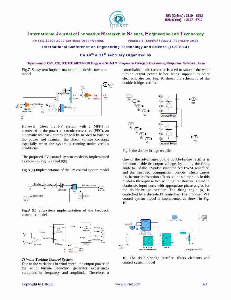
Fig.7. Subsystem implementation of the dc/dc converter model
However, when the PV system with a MPPT is connected to the power electronic converters (PEC), an automatic feedback controller will be needed to balance the power and maintain the direct voltage constant; especially when the system is running under various conditions. The proposed PV control system model is implemented as shown in Fig. 8(a) and 8(b). Fig.8 (a) Implementation of the PV control system model
Fig.8 (b) Subsystem implementation of the feedback controller model
2) Wind Turbine Control System Due to the variations in wind speed, the output power of the wind turbine induction generator experiences variations in frequency and amplitude. Therefore, a
controllable ac/dc converter is used to smooth the wind turbine output power before being supplied to other electronic devices. Fig. 9, shows the schematic of the double-bridge rectifier.
Fig.9. the double-bridge rectifier One of the advantages of the double-bridge rectifier is the controllable dc output voltage, by tuning the firing angle (α) of the 12-pulse synchronized PWM generator, and the narrowed commutation periods, which causes less harmonic distortion effects on the source side. In this model a three-phase two winding transformer is used to obtain six input ports with appropriate phase angles for the double-bridge rectifier. The firing angle (α) is controlled by a discrete PI controller. The proposed WT control system model is implemented as shown in Fig. 10.
10. The double-bridge rectifier, filters elements and control system model

ISSN (Online) : 2319 – 8753 ISSN (Print) : 2347 - 6710
International Journal of Innovative Research in Science, Engineering and Technology
An ISO 3297: 2007 Certified Organization, Volume 3, Special Issue 1, February 2014
International Conference on Engineering Technology and Science-(ICETS’14)
On 10th & 11th February Organized by
Department of CIVIL, CSE, ECE, EEE, MECHNICAL Engg. and S&H of Muthayammal College of Engineering, Rasipuram, Tamilnadu, India
Copyright to IJIRSET www.ijirset.com 925
3) dc/ac inverter for load side An ac averaged switched model inverter is built and implemented using MATLAB/SIMULINK, to convert the direct current (dc) into alternating current (ac), at a switching frequency (FS) greater than the AC line frequency (50Hz - 60Hz). Losses are included due to output-port series resistance (ROP) and input-port switching loss current (IIP) The proposed model is implemented as shown in Fig. 11.
Fig.11. Subsystem implementation of the dc/ac inverter model
III. SIMULATION RESULTS AND DISCUSSION The block diagram of the integrated photovoltaic/wind turbine system, and the power controllers are shown in Fig. 2. The major inputs for the proposed PV model were solar irradiation, PV panel temperature and PV manufacturing data sheet information’s. In this study, Astronergy CHSM6610P PV panel is taken as example. The Astronergy CHSM6610P key specification is listed in Table I
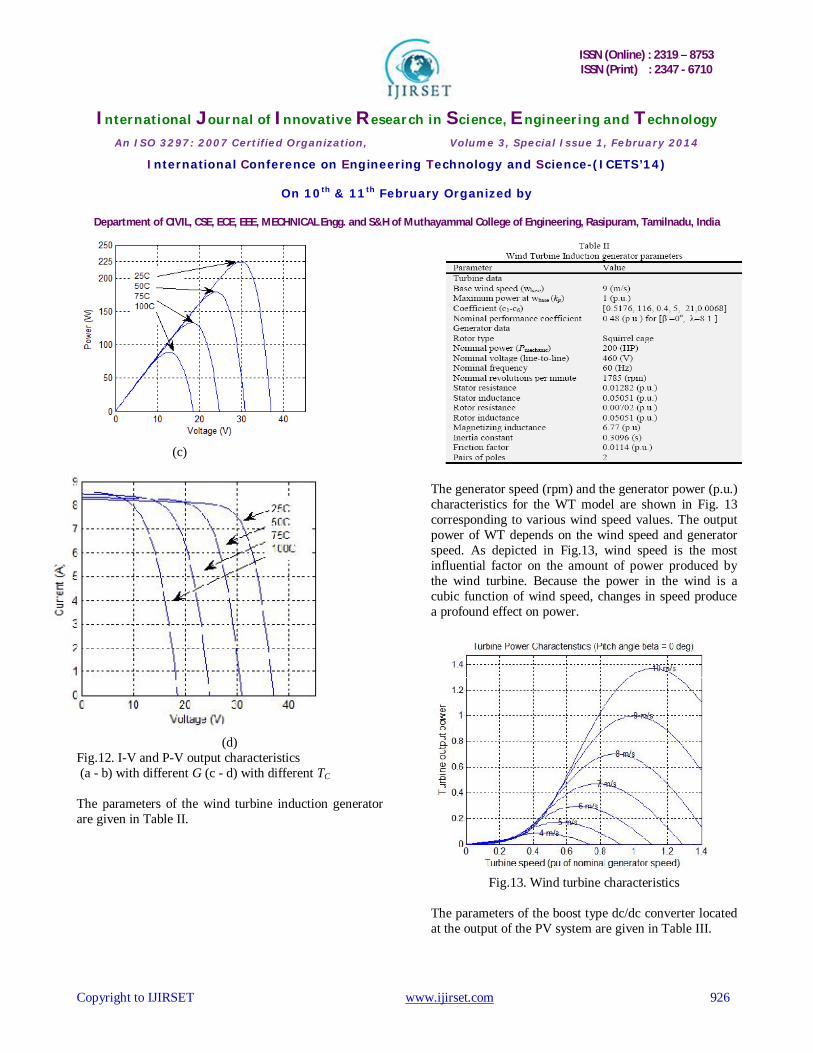
The I-V and P-V output characteristics for the PV model are shown in Fig.12. The output power and current of PV module depend on the solar irradiance and temperature, and cell’s terminal operating voltage as well. It was found from Fig. 12(a) and 12(b) that with increased solar irradiance there is an increase in both the maximum power output and the short circuit current. On the other hand, we observe from Fig. 12(c) and 12(d) that with an increase in the cell temperature, the maximum power output decreases whilst the short circuit current increases.
(a)
(b)
ISSN (Online) : 2319 – 8753 ISSN (Print) : 2347 - 6710
International Journal of Innovative Research in Science, Engineering and Technology
An ISO 3297: 2007 Certified Organization, Volume 3, Special Issue 1, February 2014
International Conference on Engineering Technology and Science-(ICETS’14)
On 10th & 11th February Organized by
Department of CIVIL, CSE, ECE, EEE, MECHNICAL Engg. and S&H of Muthayammal College of Engineering, Rasipuram, Tamilnadu, India
Copyright to IJIRSET www.ijirset.com 926
(c)
(d) Fig.12. I-V and P-V output characteristics (a - b) with different G (c - d) with different TC
The parameters of the wind turbine induction generator are given in Table II.
The generator speed (rpm) and the generator power (p.u.) characteristics for the WT model are shown in Fig. 13 corresponding to various wind speed values. The output power of WT depends on the wind speed and generator speed. As depicted in Fig.13, wind speed is the most influential factor on the amount of power produced by the wind turbine. Because the power in the wind is a cubic function of wind speed, changes in speed produce a profound effect on power.
Fig.13. Wind turbine characteristics
The parameters of the boost type dc/dc converter located at the output of the PV system are given in Table III.
ISSN (Online) : 2319 – 8753 ISSN (Print) : 2347 - 6710
International Journal of Innovative Research in Science, Engineering and Technology
An ISO 3297: 2007 Certified Organization, Volume 3, Special Issue 1, February 2014
International Conference on Engineering Technology and Science-(ICETS’14)
On 10th & 11th February Organized by
Department of CIVIL, CSE, ECE, EEE, MECHNICAL Engg. and S&H of Muthayammal College of Engineering, Rasipuram, Tamilnadu, India
Copyright to IJIRSET www.ijirset.com 927
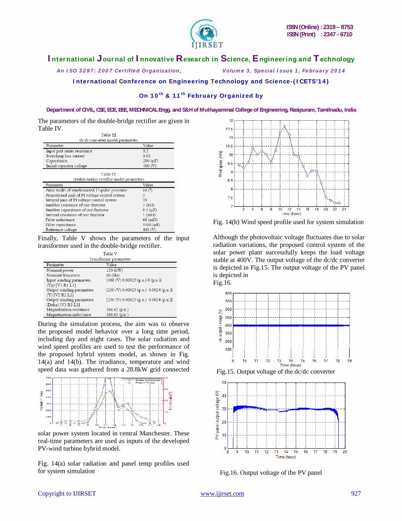
The parameters of the double-bridge rectifier are given in Table IV.
Finally, Table V shows the parameters of the input transformer used in the double-bridge rectifier.
During the simulation process, the aim was to observe the proposed model behavior over a long time period, including day and night cases. The solar radiation and wind speed profiles are used to test the performance of the proposed hybrid system model, as shown in Fig. 14(a) and 14(b). The irradiance, temperature and wind speed data was gathered from a 28.8kW grid connected
solar power system located in central Manchester. These real-time parameters are used as inputs of the developed PV-wind turbine hybrid model. Fig. 14(a) solar radiation and panel temp profiles used for system simulation
Fig. 14(b) Wind speed profile used for system simulation Although the photovoltaic voltage fluctuates due to solar radiation variations, the proposed control system of the solar power plant successfully keeps the load voltage stable at 400V. The output voltage of the dc/dc converter is depicted in Fig.15. The output voltage of the PV panel is depicted in Fig.16.
Fig.15. Output voltage of the dc/dc converter
Fig.16. Output voltage of the PV panel

ISSN (Online) : 2319 – 8753 ISSN (Print) : 2347 - 6710
International Journal of Innovative Research in Science, Engineering and Technology
An ISO 3297: 2007 Certified Organization, Volume 3, Special Issue 1, February 2014
International Conference on Engineering Technology and Science-(ICETS’14)
On 10th & 11th February Organized by
Department of CIVIL, CSE, ECE, EEE, MECHNICAL Engg. and S&H of Muthayammal College of Engineering, Rasipuram, Tamilnadu, India
Copyright to IJIRSET www.ijirset.com 928
The objective of the P&O algorithm is to adjust the dc/dc control variable (Iref) so that the PV array operates at the maximum power point (MPP). And that done, by periodically incrementing or decrementing the PV array operating current (Ipv = Iref), as shown in Fig. 17.
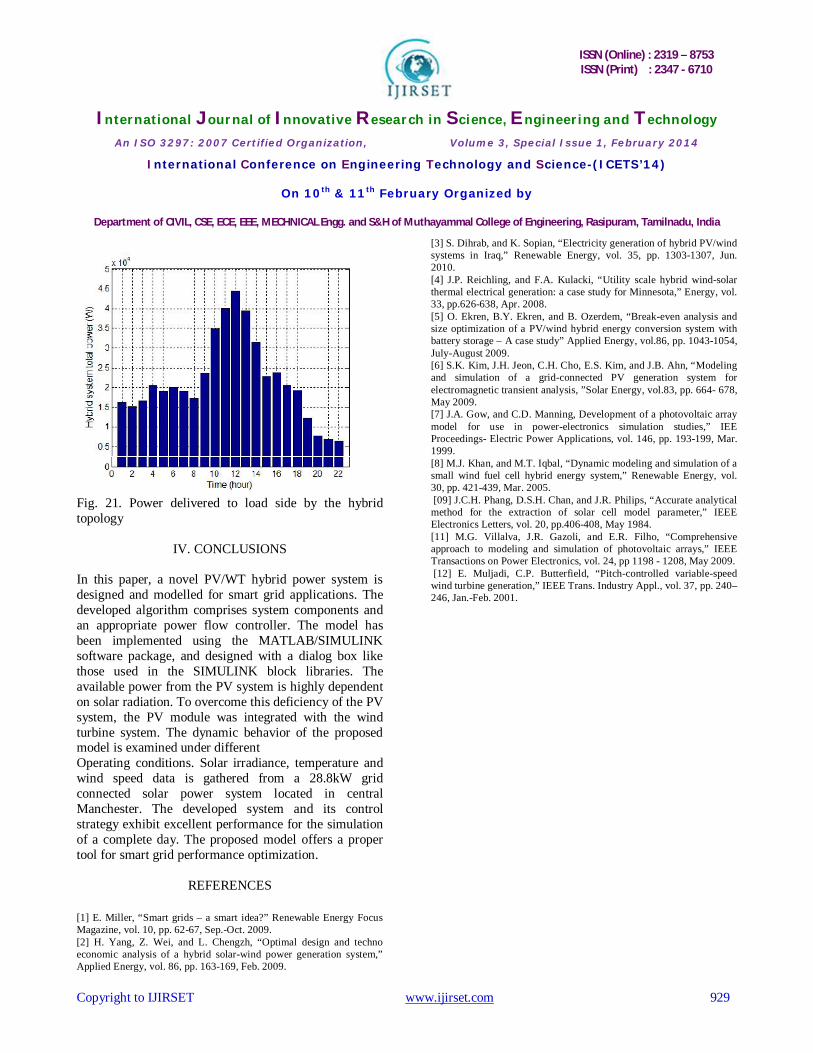
Fig.17. Output current of the MPPT (Iref = Ipv) From Fig. 18, we observe that in the early morning before 8:30am and in the evening after 19:00pm, the solar power is unavailable due to nonexistence of solar radiation. To overcome this deficiency of the PV system, and to increase the amount of power in the early morning, the wind turbine system was added to the solar power plant. In this study, the stator winding is connected to the grid and the rotor is driven by the wind turbine. The power captured by the wind turbine is converted into electrical power by the induction generator and is transmitted to the grid by the stator winding. As shown in Fig. 14(b), 24-h duration is used for the simulations with a variation in wind speed. This variation in wind speed affects the power produced by the induction Generator coupled to the wind turbine as observed in Fig. 19. From Fig. 20, we observe that although the available power from the wind generator fluctuates due to wind speed variations, the PI controlled firing angle (α) of the double bridge ac/dc converter successfully maintain Since the voltage of the two dc buses is kept at 400V, dc/ac inverters are used to deliver the required power to the load side at 60Hz frequency and 240V line-to-line voltage.
The power delivered to the load side by the PV/WT hybrid topology is illustrated in Fig. 21.s the output voltage of the WTIG at 400V.
Fig.18. Total power of the solar power plant (160 Astronergy CHSM6610P PV panel)
Fig.19. Power of the generator coupled to the wind turbine
Fig.20. Output voltage of the double-bridge ac/dc converter
ISSN (Online) : 2319 – 8753 ISSN (Print) : 2347 - 6710
International Journal of Innovative Research in Science, Engineering and Technology
An ISO 3297: 2007 Certified Organization, Volume 3, Special Issue 1, February 2014
International Conference on Engineering Technology and Science-(ICETS’14)
On 10th & 11th February Organized by
Department of CIVIL, CSE, ECE, EEE, MECHNICAL Engg. and S&H of Muthayammal College of Engineering, Rasipuram, Tamilnadu, India
Copyright to IJIRSET www.ijirset.com 929
Fig. 21. Power delivered to load side by the hybrid topology
IV. CONCLUSIONS
In this paper, a novel PV/WT hybrid power system is designed and modelled for smart grid applications. The developed algorithm comprises system components and an appropriate power flow controller. The model has been implemented using the MATLAB/SIMULINK software package, and designed with a dialog box like those used in the SIMULINK block libraries. The available power from the PV system is highly dependent on solar radiation. To overcome this deficiency of the PV system, the PV module was integrated with the wind turbine system. The dynamic behavior of the proposed model is examined under different Operating conditions. Solar irradiance, temperature and wind speed data is gathered from a 28.8kW grid connected solar power system located in central Manchester. The developed system and its control strategy exhibit excellent performance for the simulation of a complete day. The proposed model offers a proper tool for smart grid performance optimization.
REFERENCES
[1] E. Miller, “Smart grids – a smart idea?” Renewable Energy Focus Magazine, vol. 10, pp. 62-67, Sep.-Oct. 2009. [2] H. Yang, Z. Wei, and L. Chengzh, “Optimal design and techno economic analysis of a hybrid solar-wind power generation system,” Applied Energy, vol. 86, pp. 163-169, Feb. 2009.
[3] S. Dihrab, and K. Sopian, “Electricity generation of hybrid PV/wind systems in Iraq,” Renewable Energy, vol. 35, pp. 1303-1307, Jun. 2010. [4] J.P. Reichling, and F.A. Kulacki, “Utility scale hybrid wind-solar thermal electrical generation: a case study for Minnesota,” Energy, vol. 33, pp.626-638, Apr. 2008. [5] O. Ekren, B.Y. Ekren, and B. Ozerdem, “Break-even analysis and size optimization of a PV/wind hybrid energy conversion system with battery storage – A case study” Applied Energy, vol.86, pp. 1043-1054, July-August 2009. [6] S.K. Kim, J.H. Jeon, C.H. Cho, E.S. Kim, and J.B. Ahn, “Modeling and simulation of a grid-connected PV generation system for electromagnetic transient analysis, ”Solar Energy, vol.83, pp. 664- 678, May 2009. [7] J.A. Gow, and C.D. Manning, Development of a photovoltaic array model for use in power-electronics simulation studies,” IEE Proceedings- Electric Power Applications, vol. 146, pp. 193-199, Mar. 1999. [8] M.J. Khan, and M.T. Iqbal, “Dynamic modeling and simulation of a small wind fuel cell hybrid energy system,” Renewable Energy, vol. 30, pp. 421-439, Mar. 2005. [09] J.C.H. Phang, D.S.H. Chan, and J.R. Philips, “Accurate analytical method for the extraction of solar cell model parameter,” IEEE Electronics Letters, vol. 20, pp.406-408, May 1984. [11] M.G. Villalva, J.R. Gazoli, and E.R. Filho, “Comprehensive approach to modeling and simulation of photovoltaic arrays,” IEEE Transactions on Power Electronics, vol. 24, pp 1198 - 1208, May 2009. [12] E. Muljadi, C.P. Butterfield, “Pitch-controlled variable-speed wind turbine generation,” IEEE Trans. Industry Appl., vol. 37, pp. 240– 246, Jan.-Feb. 2001.